The document outlines the Computer Networks course (integrated module 1) taught by Dr. Shivashankar at Global Academy of Technology, focusing on key elements such as the internet protocol, network layer routing, UDP and TCP protocols, wireless networking, and network security algorithms. It details network layer functions including routing, forwarding, and fragmentation, along with a comprehensive overview of IP addressing and the introduction of IPv6. Students completing the course will acquire a foundational understanding of these networking concepts, essential for efficient data communication.
Introduction to Computer Networks, course outcomes including concepts like Internet Protocol, transport protocols, and network security.
Overview of the Network Layer in TCP/IP, defining functions like routing, logical addressing and fragmentation.
Functions of the network layer include forwarding packets via forwarding tables and routing to enhance communication efficiency.
Properties of network services such as guaranteed delivery, in-order delivery, minimal bandwidth, and various security services.
Key components of a router including input ports, switching fabric, output ports, and their respective roles in data forwarding.
Explains how queuing occurs, output processing, and an introduction to the Internet Protocol (IP) and datagram structure.
IPv4 datagram fields and unique address composition, detailing network, host, and subnet parts.
Dynamic Host Configuration Protocol (DHCP) usage for automatic IP address allocation and ICMP for error reporting in networks.
Highlighting IPv6 features, packet structure, and benefits compared to IPv4 such as vast address space and improved routing.
Discussion on the Link State Routing Algorithm, its characteristics, functionalities, and solving example problems.
Steps in the Link State Routing Algorithm and examples of constructing routing tables with detailed paths.
Description of Distance Vector Routing protocol with equations, examples for calculating node distances, algorithm details.
Hierarchical routing strategies to manage large networks, including division into regions and clusters.
Intra-AS Routing concepts with protocols like RIP and OSPF defined, emphasizing their functionalities.
Features of RIP as a distance-vector routing protocol, including its operation and update mechanisms.
Functionality of OSPF as an intra-AS routing protocol using link-state routing to build routing tables.
Characteristics and importance of BGP for inter-AS routing, emphasizing security and path selection.Overview of the transport layer's purpose, including communication services and the role of TCP and UDP.
UDP characteristics including connectionless communication and checksum functions for error detection.
Details on UDP checksum calculations and how it verifies data integrity during transmission.
COMPUTER NETWORKS (INTEGRATED)
(22ISE52)
Module 1+
Dr. Shivashankar
Professor
Department of Information Science & Engineering
GLOBAL ACADEMY OF TECHNOLOGY-Bengaluru
11/15/2024 1
Dr. Shivashankar, ISE, GAT
GLOBAL ACADEMY OF TECHNOLOGY
Ideal Homes Township, Rajarajeshwari Nagar, Bengaluru – 560 098
Department of Information Science & Engineering
2.
Course Outcomes
After Completionof the course, student will be able to:
Describe the Internet Protocol and network layer routing algorithms.
Explain transport layer UDP and TCP protocols services.
Describe and demonstrate of application layer protocol and its supporting
protocols.
Discuss the wireless and mobile network covering IEEE 802.11 standard
Describe the different network security algorithms.
Text Book:
1. James F Kurose and Keith W Ross, Computer Networking, A Top-Down
Approach, Sixth edition, Pearson,2017.
Reference Books:
1. Behrouz A Forouzan, Data and Communications and Networking, Fifth
Edition, McGraw Hill, Indian Edition
2. Larry L Peterson and Brusce S Davie, Computer Networks, fifth edition,
ELSEVIER
3. Andrew S Tanenbaum, Computer Networks, fifth edition, Pearson
4. Mayank Dave, Computer Networks, Second edition, Cengage Learning
11/15/2024 2
Dr. Shivashankar, ISE, GAT
3.
MODULE-1
INTRODUCTION NETWORK LAYER
•The Network Layer is the third layer of the TCP/IP suite.
• It handles the service requests from the transport layer and further
forwards the service request to the data link layer.
• Also known as the Internet layer, is the part of the TCP/IP model that
manages the flow and routing of data packets between networks.
• The network layer translates the logical addresses into physical addresses
• The main functions performed by the network layer are:
Routing:
Logical Addressing: An IP address: Example:120.150. 1.4.
Internetworking:
This is the main role of the network layer that it provides the logical
connection between different types of networks.
Fragmentation:
The fragmentation is a process of breaking the packets into the smallest
individual data units that travel through different networks.
11/15/2024 3
Dr. Shivashankar, ISE, GAT
4.
Forwarding and Routing
•The main function of Network layer is to move packets from a sending host to
a receiving host.
• To do so, two important network-layer functions can be identified:
1. Forwarding:
• The process of transferring packets from an input link interface to an output
link interface on a router.
• It involves: Verifying the IP header, Extracting the destination address, Looking
up the destination address, and Adjusting the time-to-live field in the IP
header.
• 2. Routing:
• The process of selecting a path for traffic in a network or between or across
multiple networks.
• It makes network communication more efficient and reliable.
• There are three types of routing: static, default, and dynamic.
• It refers to the network-wide process that determines the end-to-end paths
that packets take from source to destination.
11/15/2024 4
Dr. Shivashankar, ISE, GAT
5.
Conti…
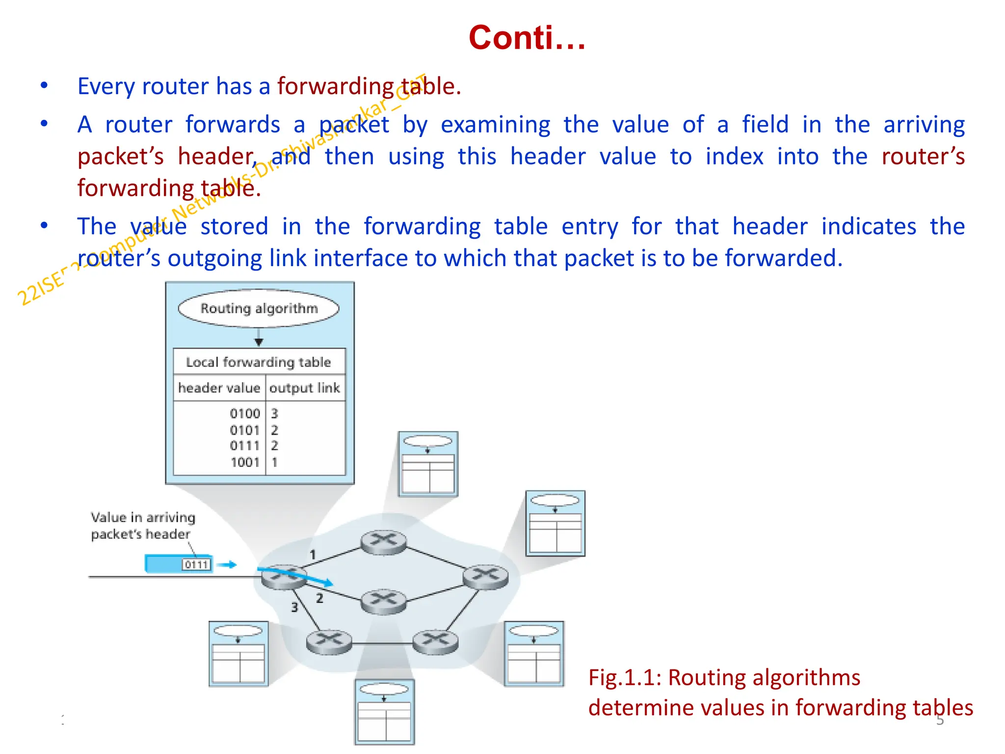
• Every routerhas a forwarding table.
• A router forwards a packet by examining the value of a field in the arriving
packet’s header, and then using this header value to index into the router’s
forwarding table.
• The value stored in the forwarding table entry for that header indicates the
router’s outgoing link interface to which that packet is to be forwarded.
11/15/2024 5
Dr. Shivashankar, ISE, GAT
Fig.1.1: Routing algorithms
determine values in forwarding tables
6.
Network Service Models
Thenetwork service model defines the characteristics of end-to-end transport of
packets between sending and receiving end systems.
Some services provided by the network layer include:
• Guaranteed delivery:
This service guarantees that the packet will eventually arrive at its destination.
• Guaranteed delivery with bounded delay:
A network layer service that ensures packets are delivered to their destination
within a specified time limit.
This service is intended for applications that require a firm guarantee that
packets will arrive within a certain delay bound.
Services could be provided to a flow of packets between a given source and
destination:
• In-order packet delivery:
the process of ensuring that packets are delivered to the destination in the same
order they were sent.
Guaranteed minimal bandwidth:
This network-layer service emulates the behavior of a transmission link of a
specified bit rate.
11/15/2024 6
Dr. Shivashankar, ISE, GAT
7.
Conti..
• Guaranteed maximumjitter:
The variation in the time delay between when a signal is transmitted and
received over a network connection.
It's a measure of how inconsistent the delay is between packets.
• Security services:
1. Access control
The first stage of network security, access control prevents malware and viruses
from breaching the network security system
2. Secure protocols
The use of secure protocols like HTTPS can help with network security.
3. Network segmentation
Separating sensitive and less sensitive parts of the network can help with
network security.
4. Anti-malware and antivirus software
These security solutions monitor and analyze network traffic for malicious
activity.
11/15/2024 7
Dr. Shivashankar, ISE, GAT
8.
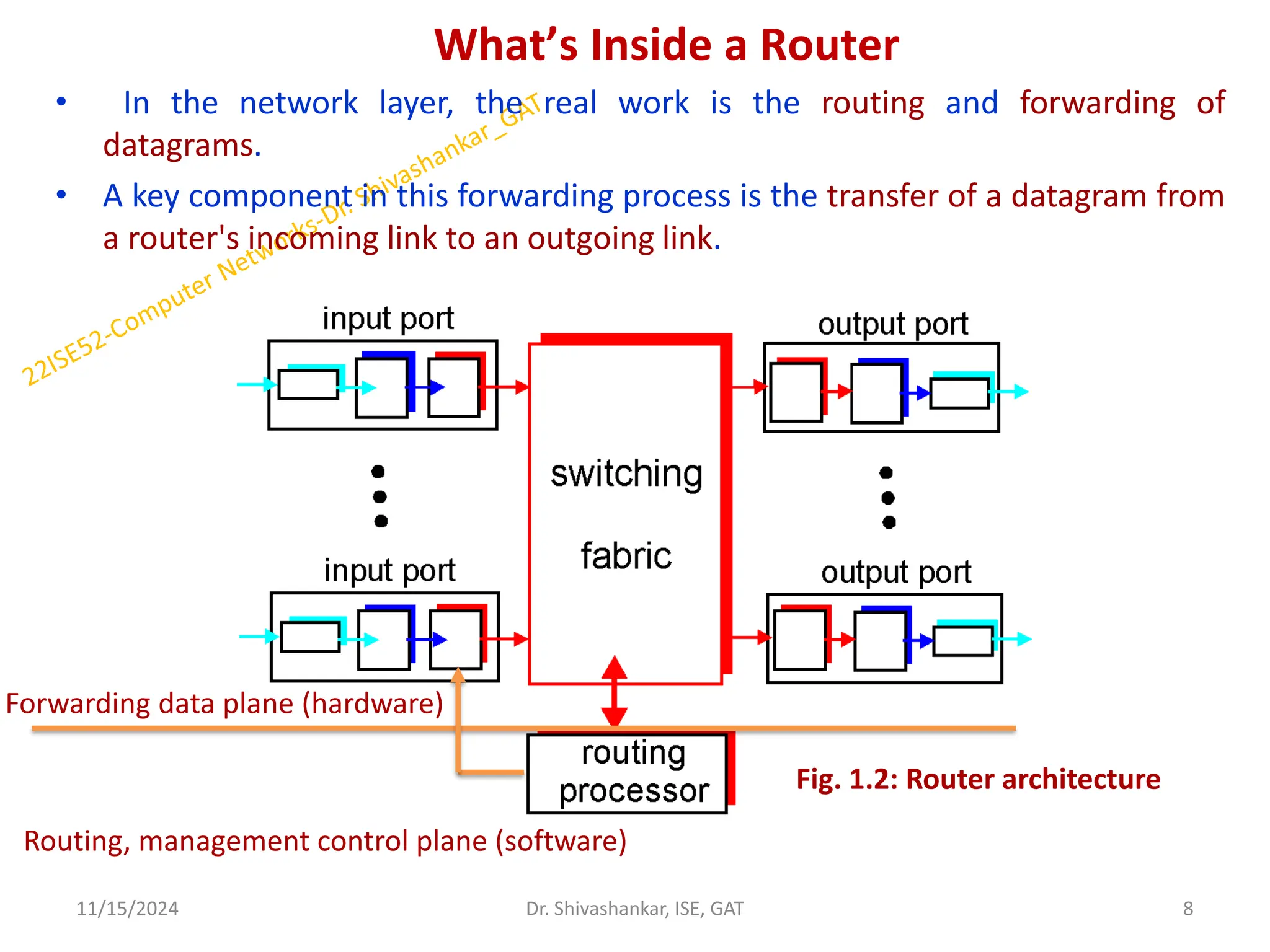
What’s Inside aRouter
• In the network layer, the real work is the routing and forwarding of
datagrams.
• A key component in this forwarding process is the transfer of a datagram from
a router's incoming link to an outgoing link.
11/15/2024 8
Dr. Shivashankar, ISE, GAT
Fig. 1.2: Router architecture
Routing, management control plane (software)
Forwarding data plane (hardware)
9.
CONTI…
Four components ofa router can be identified:
1. Input ports:
It performs the physical layer functionality of terminating an incoming physical
link to a router.
It performs the data link layer functionality needed to interoperate with the data.
It also performs a lookup and forwarding function so that a datagram forwarded.
Control packets are forwarded from the input port to the routing processor.
2. Switching fabric:
The switching fabric connects the router's input ports to its output ports.
This switching fabric is completely contained with the router - a network inside of
a network router!
3. Output ports:
An output port stores the datagrams that have been forwarded to it through the
switching fabric, and then transmits the datagrams on the outgoing link. And it
performs the reverse data link and physical layer functionality as the input port.
4. Routing processor:
The routing processor executes the routing protocols, maintains the routing
tables, and performs network management functions, within the router.
11/15/2024 9
Dr. Shivashankar, ISE, GAT
10.
Input Processing
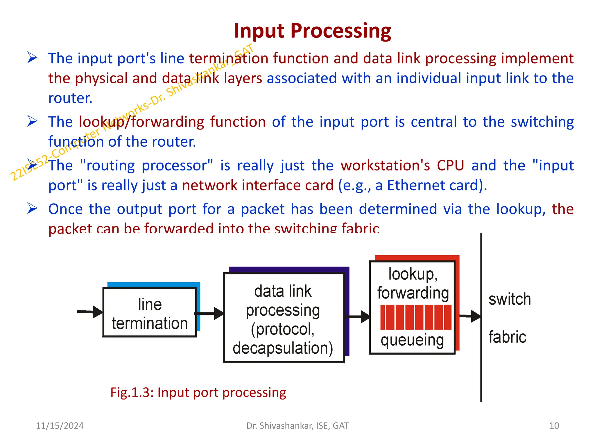
Theinput port's line termination function and data link processing implement
the physical and data link layers associated with an individual input link to the
router.
The lookup/forwarding function of the input port is central to the switching
function of the router.
The "routing processor" is really just the workstation's CPU and the "input
port" is really just a network interface card (e.g., a Ethernet card).
Once the output port for a packet has been determined via the lookup, the
packet can be forwarded into the switching fabric
11/15/2024 10
Dr. Shivashankar, ISE, GAT
Fig.1.3: Input port processing
11.
Switching Fabrics
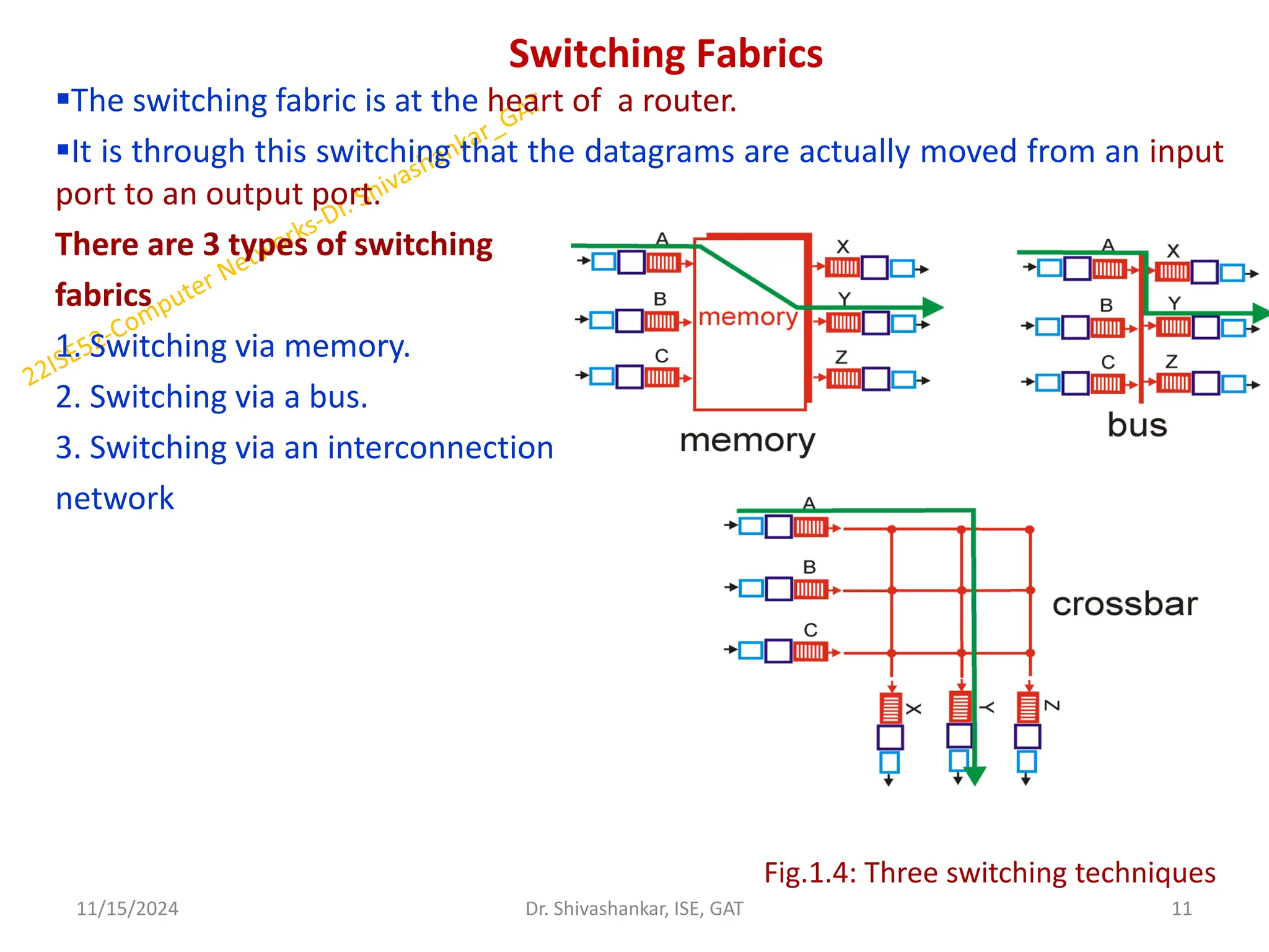
The switchingfabric is at the heart of a router.
It is through this switching that the datagrams are actually moved from an input
port to an output port.
There are 3 types of switching
fabrics
1. Switching via memory.
2. Switching via a bus.
3. Switching via an interconnection
network
11/15/2024 11
Dr. Shivashankar, ISE, GAT
Fig.1.4: Three switching techniques
12.
Output Processing
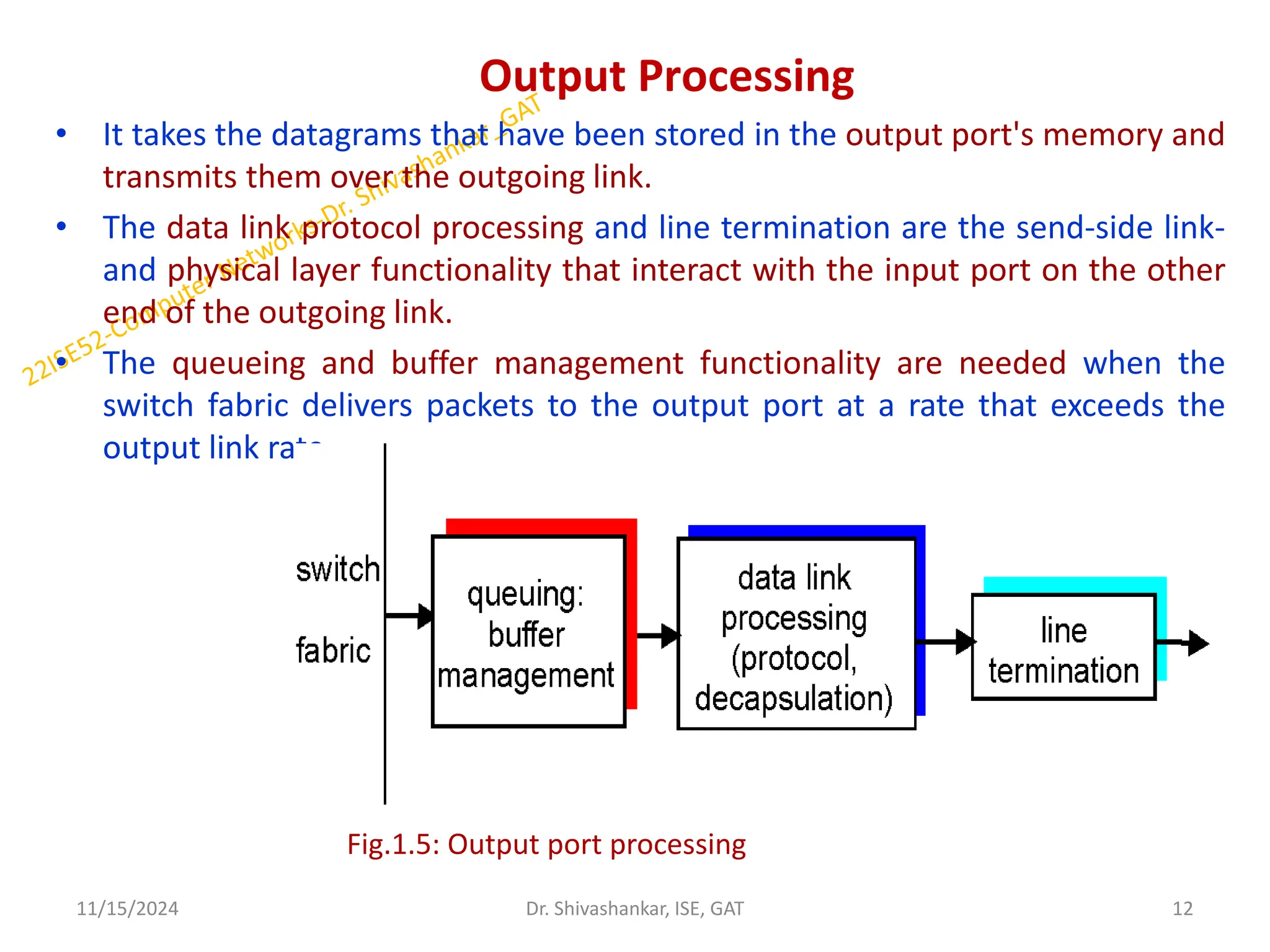
• Ittakes the datagrams that have been stored in the output port's memory and
transmits them over the outgoing link.
• The data link protocol processing and line termination are the send-side link-
and physical layer functionality that interact with the input port on the other
end of the outgoing link.
• The queueing and buffer management functionality are needed when the
switch fabric delivers packets to the output port at a rate that exceeds the
output link rate.
11/15/2024 12
Dr. Shivashankar, ISE, GAT
Fig.1.5: Output port processing
13.
Where Does QueueingOccur?
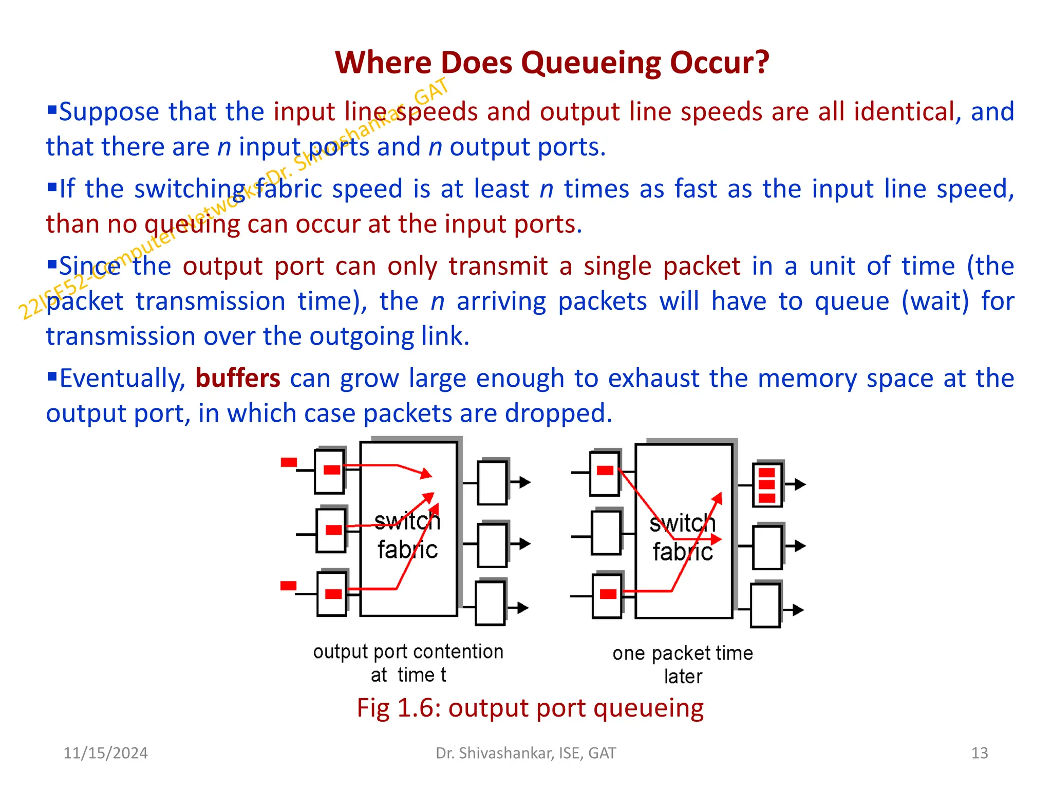
Suppose that the input line speeds and output line speeds are all identical, and
that there are n input ports and n output ports.
If the switching fabric speed is at least n times as fast as the input line speed,
than no queuing can occur at the input ports.
Since the output port can only transmit a single packet in a unit of time (the
packet transmission time), the n arriving packets will have to queue (wait) for
transmission over the outgoing link.
Eventually, buffers can grow large enough to exhaust the memory space at the
output port, in which case packets are dropped.
Fig 1.6: output port queueing
11/15/2024 13
Dr. Shivashankar, ISE, GAT
14.
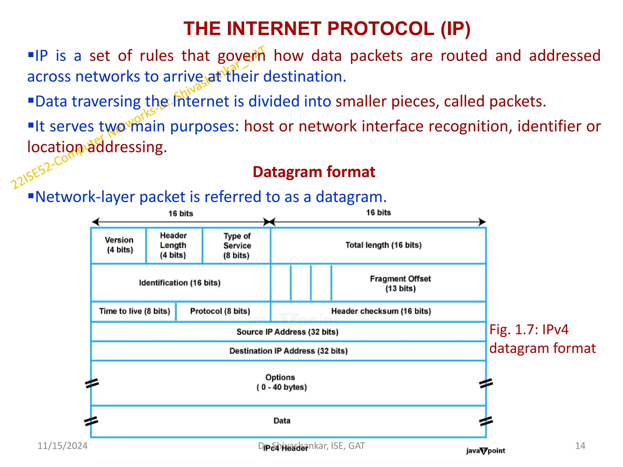
THE INTERNET PROTOCOL(IP)
IP is a set of rules that govern how data packets are routed and addressed
across networks to arrive at their destination.
Data traversing the Internet is divided into smaller pieces, called packets.
It serves two main purposes: host or network interface recognition, identifier or
location addressing.
Datagram format
Network-layer packet is referred to as a datagram.
11/15/2024 14
Dr. Shivashankar, ISE, GAT
Fig. 1.7: IPv4
datagram format
15.
Conti..
The key fieldsin the IPv4 datagram are the following:
Version (4 bits): This field specifies the version of the IP protocol being used,
which is IPv4 in this case.
Header Length (4 bits): The header length field indicates the length of the IPv4
header in 32-bit words. Since the header is a fixed size of 20 bytes, the value of
this field is typically 5.
Type of Service (8 bits): This field is used to define the Quality of Service (QoS) for
the packet, including priorities and other parameters for routing and processing.
Total Length (16 bits): The total length field specifies the length of the entire IPv4
packet, including both the header and the data, in bytes.
Identification (16 bits): The identification field is used for packet fragmentation
and reassembly. It helps in grouping fragments of a larger packet together.
Flags (3 bits): These bits are used for controlling and identifying packet
fragmentation. The flags include the "Don't Fragment" (DF) and "More
Fragments" (MF) flags.
11/15/2024 15
Dr. Shivashankar, ISE, GAT
16.
CONTI…
Fragment Offset (13bits): The fragment offset field specifies the position of the
fragment within the original packet. It is used to reassemble fragmented packets
correctly.
Time to Live (TTL) (8 bits): The TTL field represents the maximum number of hops
(routers or network segments) that the packet can traverse before it is discarded.
Each router decrements this value by one.
Protocol (8 bits): This field indicates the type of protocol used in the data portion
of the packet, such as TCP, UDP, ICMP, or others.
Header Checksum (16 bits): The header checksum field is used to verify the
integrity of the IPv4 header during transmission. Routers and devices recalculate
this checksum to check for errors.
Source IP Address (32 bits): This field contains the IP address of the sender or
source of the packet.
Destination IP Address (32 bits): This field holds the IP address of the recipient or
destination of the packet.
11/15/2024 16
Dr. Shivashankar, ISE, GAT
17.
IPv4 Addressing
The mostwidely used system for identifying devices on a network. It uses a set
of four numbers, separated by periods (like 192.168.0.1), to give each device a
unique address.
This address helps data find its way from one device to another over the
internet.
Parts of IPv4
IPv4 addresses consist of three parts:
Network Part: The network part indicates the distinctive variety that’s appointed
to the network. The network part conjointly identifies the category of the
network that’s assigned.
Host Part: The host part uniquely identifies the machine on your network. This
part of the IPv4 address is assigned to every host.
For each host on the network, the network part is the same, however, the host
half must vary.
Subnet Number: This is the nonobligatory part of IPv4. Local networks that have
massive numbers of hosts are divided into subnets and subnet numbers are
appointed to that.
11/15/2024 17
Dr. Shivashankar, ISE, GAT
18.
CONTI…
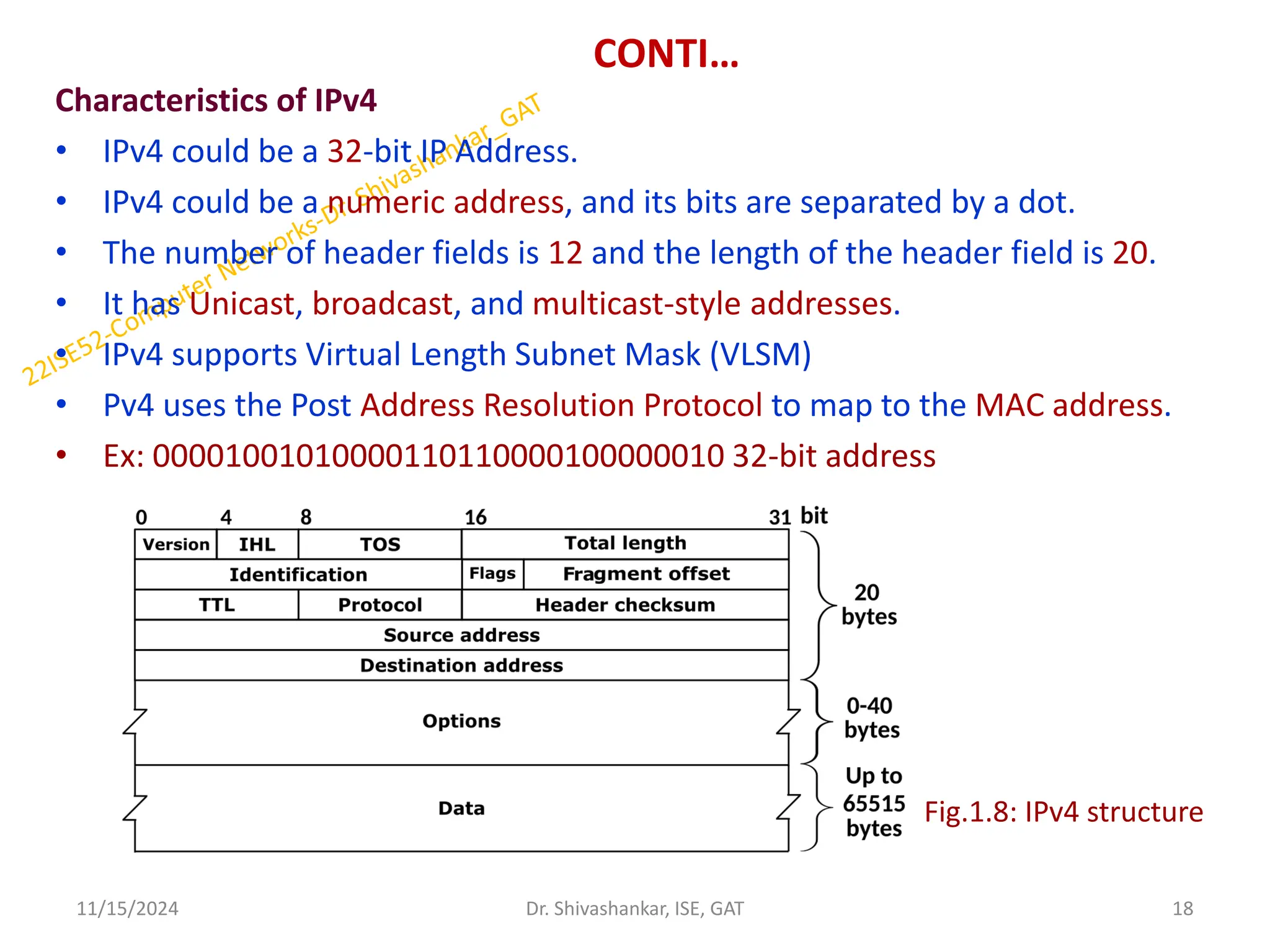
Characteristics of IPv4
•IPv4 could be a 32-bit IP Address.
• IPv4 could be a numeric address, and its bits are separated by a dot.
• The number of header fields is 12 and the length of the header field is 20.
• It has Unicast, broadcast, and multicast-style addresses.
• IPv4 supports Virtual Length Subnet Mask (VLSM)
• Pv4 uses the Post Address Resolution Protocol to map to the MAC address.
• Ex: 00001001010000110110000100000010 32-bit address
11/15/2024 18
Dr. Shivashankar, ISE, GAT
Fig.1.8: IPv4 structure
19.
Dynamic Host ConfigurationProtocol
• Host addresses can also be configured manually, but more often this task is
now done using the Dynamic Host Configuration Protocol (DHCP) [RFC 2131].
• DHCP allows a host to obtain (be allocated) an IP address automatically.
• Because of DHCP’s ability to automate the network-related aspects of
connecting a host into a network, it is often referred to as a plug-and-play
protocol.
11/15/2024 19
Dr. Shivashankar, ISE, GAT
Fig.1.9: DHCP Client Server
Interaction
20.
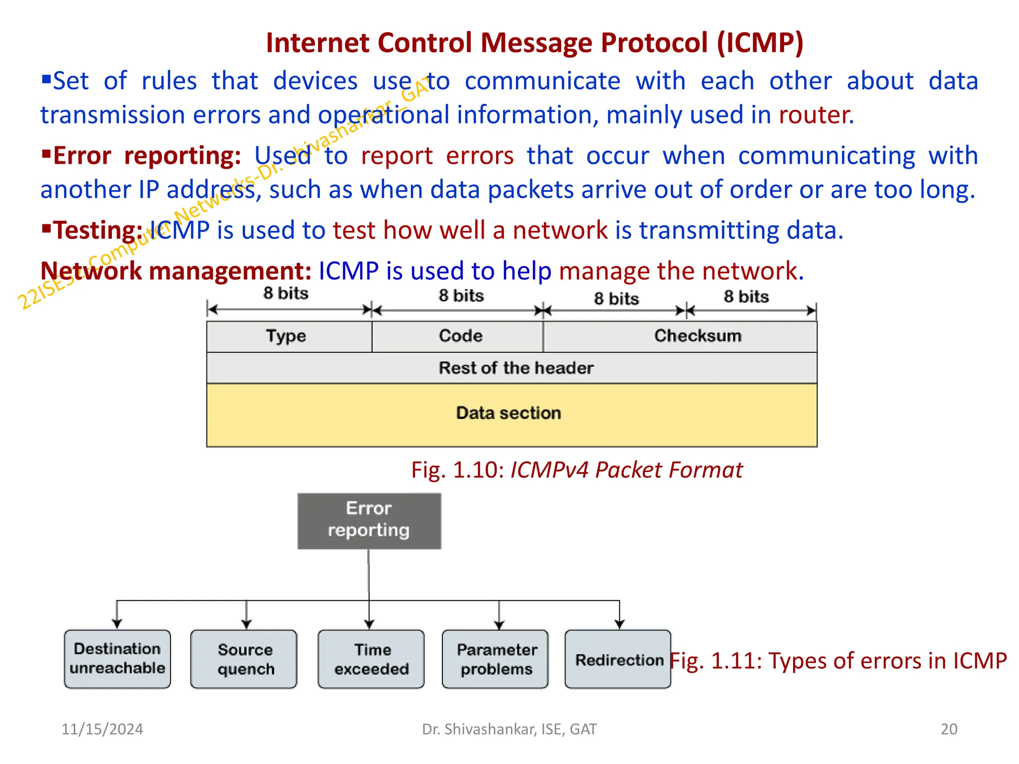
Internet Control MessageProtocol (ICMP)
Set of rules that devices use to communicate with each other about data
transmission errors and operational information, mainly used in router.
Error reporting: Used to report errors that occur when communicating with
another IP address, such as when data packets arrive out of order or are too long.
Testing: ICMP is used to test how well a network is transmitting data.
Network management: ICMP is used to help manage the network.
11/15/2024 20
Dr. Shivashankar, ISE, GAT
Fig. 1.10: ICMPv4 Packet Format
Fig. 1.11: Types of errors in ICMP
21.
CONTI…
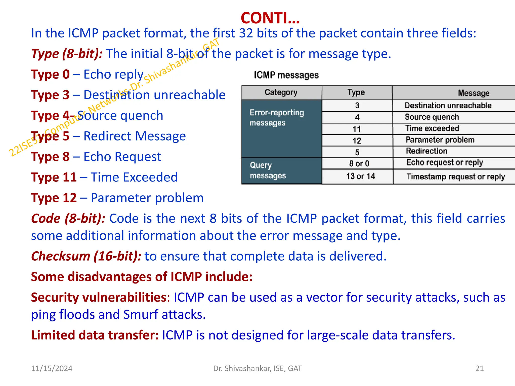
In the ICMPpacket format, the first 32 bits of the packet contain three fields:
Type (8-bit): The initial 8-bit of the packet is for message type.
Type 0 – Echo reply
Type 3 – Destination unreachable
Type 4- Source quench
Type 5 – Redirect Message
Type 8 – Echo Request
Type 11 – Time Exceeded
Type 12 – Parameter problem
Code (8-bit): Code is the next 8 bits of the ICMP packet format, this field carries
some additional information about the error message and type.
Checksum (16-bit): to ensure that complete data is delivered.
Some disadvantages of ICMP include:
Security vulnerabilities: ICMP can be used as a vector for security attacks, such as
ping floods and Smurf attacks.
Limited data transfer: ICMP is not designed for large-scale data transfers.
11/15/2024 21
Dr. Shivashankar, ISE, GAT
22.
Internet Protocol Version6 (IPv6)
IPv6 is the most recent version of the Internet Protocol,
the communications protocol that provides an identification and
location system for computers on networks and routes traffic across
the Internet.
It is an Internet Layer protocol for packet-switched internetworking and
provides end-to-end datagram transmission across multiple IP
networks.
An IPv6 packet has two parts: a header and payload.
The header consists of a fixed portion with minimal functionality
required for all packets and may be followed by optional extensions to
implement special features.
The fixed header occupies the first 40 octets (320 bits) of the IPv6
packet.
It contains the source and destination addresses, traffic class, hop
count, and the type of the optional extension or payload which follows
the header.
11/15/2024 22
Dr. Shivashankar, ISE, GAT
23.
CONTI…
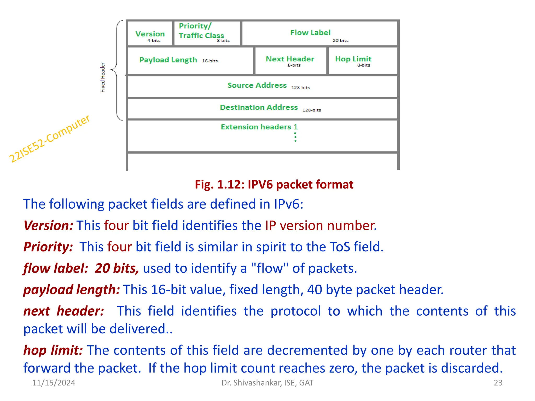
The following packetfields are defined in IPv6:
Version: This four bit field identifies the IP version number.
Priority: This four bit field is similar in spirit to the ToS field.
flow label: 20 bits, used to identify a "flow" of packets.
payload length: This 16-bit value, fixed length, 40 byte packet header.
next header: This field identifies the protocol to which the contents of this
packet will be delivered..
hop limit: The contents of this field are decremented by one by each router that
forward the packet. If the hop limit count reaches zero, the packet is discarded.
11/15/2024 23
Dr. Shivashankar, ISE, GAT
Fig. 1.12: IPV6 packet format
24.
CONTI…
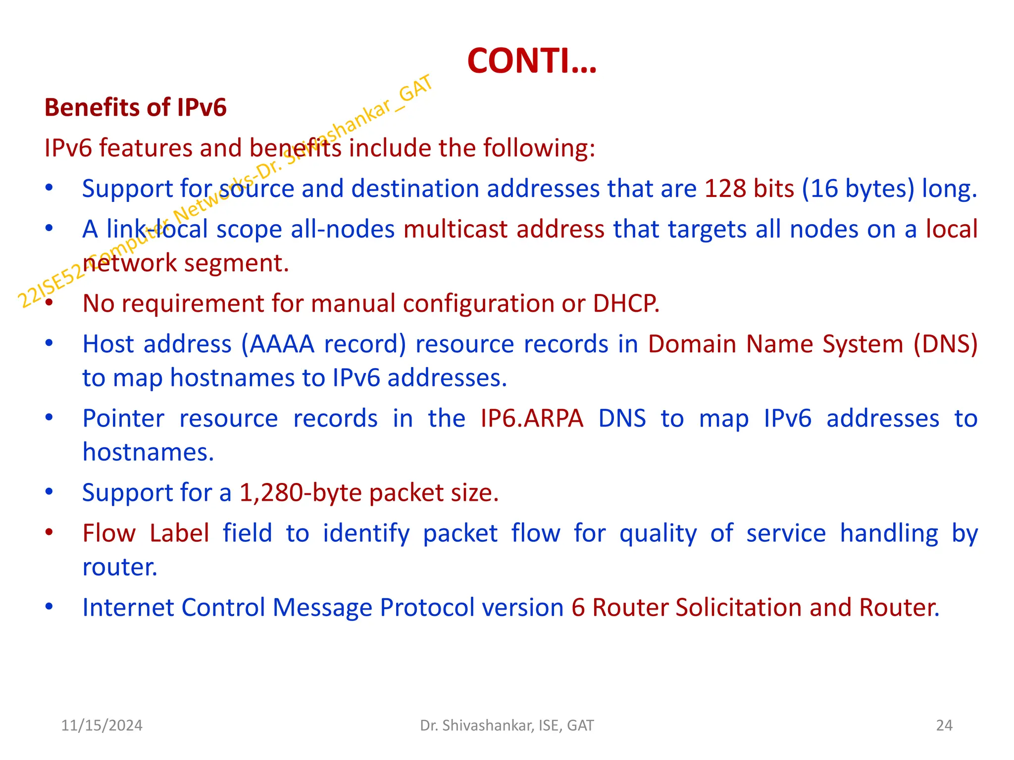
Benefits of IPv6
IPv6features and benefits include the following:
• Support for source and destination addresses that are 128 bits (16 bytes) long.
• A link-local scope all-nodes multicast address that targets all nodes on a local
network segment.
• No requirement for manual configuration or DHCP.
• Host address (AAAA record) resource records in Domain Name System (DNS)
to map hostnames to IPv6 addresses.
• Pointer resource records in the IP6.ARPA DNS to map IPv6 addresses to
hostnames.
• Support for a 1,280-byte packet size.
• Flow Label field to identify packet flow for quality of service handling by
router.
• Internet Control Message Protocol version 6 Router Solicitation and Router.
11/15/2024 24
Dr. Shivashankar, ISE, GAT
25.
CONTI…
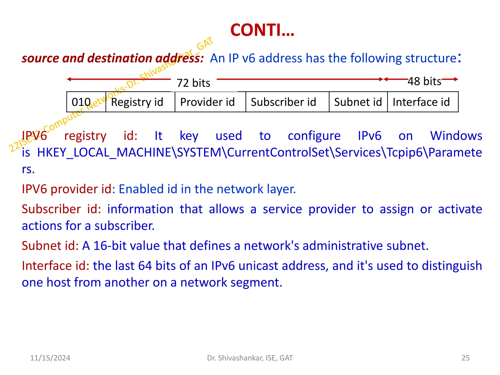
source and destinationaddress: An IP v6 address has the following structure:
IPV6 registry id: It key used to configure IPv6 on Windows
is HKEY_LOCAL_MACHINESYSTEMCurrentControlSetServicesTcpip6Paramete
rs.
IPV6 provider id: Enabled id in the network layer.
Subscriber id: information that allows a service provider to assign or activate
actions for a subscriber.
Subnet id: A 16-bit value that defines a network's administrative subnet.
Interface id: the last 64 bits of an IPv6 unicast address, and it's used to distinguish
one host from another on a network segment.
11/15/2024 25
Dr. Shivashankar, ISE, GAT
010 Registry id Provider id Subscriber id Subnet id Interface id
72 bits bits 48 bits bits
26.
Conti..
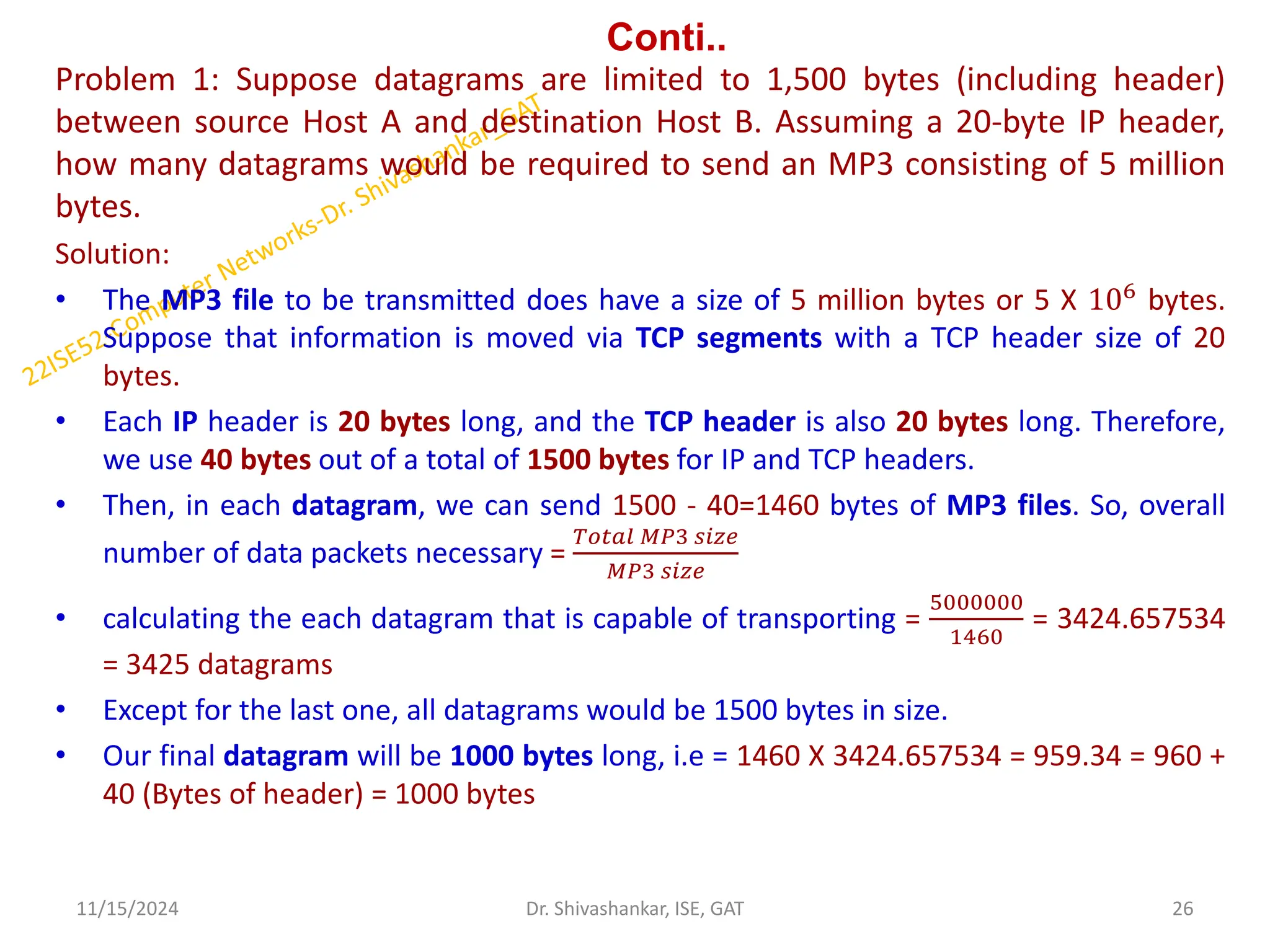
Problem 1: Supposedatagrams are limited to 1,500 bytes (including header)
between source Host A and destination Host B. Assuming a 20-byte IP header,
how many datagrams would be required to send an MP3 consisting of 5 million
bytes.
Solution:
• The MP3 file to be transmitted does have a size of 5 million bytes or 5 X 106 bytes.
Suppose that information is moved via TCP segments with a TCP header size of 20
bytes.
• Each IP header is 20 bytes long, and the TCP header is also 20 bytes long. Therefore,
we use 40 bytes out of a total of 1500 bytes for IP and TCP headers.
• Then, in each datagram, we can send 1500 - 40=1460 bytes of MP3 files. So, overall
number of data packets necessary =
𝑇𝑜𝑡𝑎𝑙 𝑀𝑃3 𝑠𝑖𝑧𝑒
𝑀𝑃3 𝑠𝑖𝑧𝑒
• calculating the each datagram that is capable of transporting =
5000000
1460
= 3424.657534
= 3425 datagrams
• Except for the last one, all datagrams would be 1500 bytes in size.
• Our final datagram will be 1000 bytes long, i.e = 1460 X 3424.657534 = 959.34 = 960 +
40 (Bytes of header) = 1000 bytes
11/15/2024 26
Dr. Shivashankar, ISE, GAT
27.
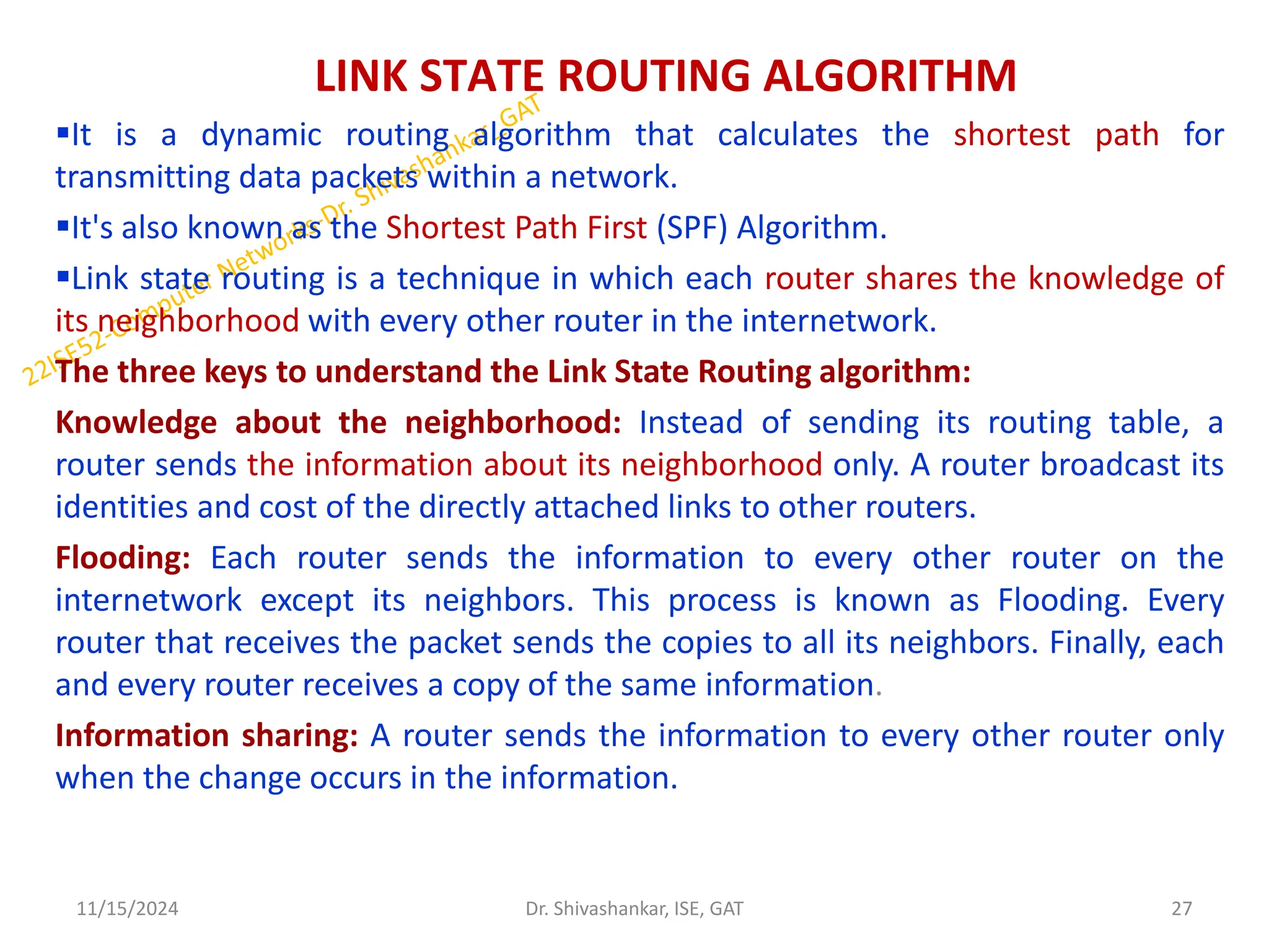
LINK STATE ROUTINGALGORITHM
It is a dynamic routing algorithm that calculates the shortest path for
transmitting data packets within a network.
It's also known as the Shortest Path First (SPF) Algorithm.
Link state routing is a technique in which each router shares the knowledge of
its neighborhood with every other router in the internetwork.
The three keys to understand the Link State Routing algorithm:
Knowledge about the neighborhood: Instead of sending its routing table, a
router sends the information about its neighborhood only. A router broadcast its
identities and cost of the directly attached links to other routers.
Flooding: Each router sends the information to every other router on the
internetwork except its neighbors. This process is known as Flooding. Every
router that receives the packet sends the copies to all its neighbors. Finally, each
and every router receives a copy of the same information.
Information sharing: A router sends the information to every other router only
when the change occurs in the information.
11/15/2024 27
Dr. Shivashankar, ISE, GAT
28.
CONTI…
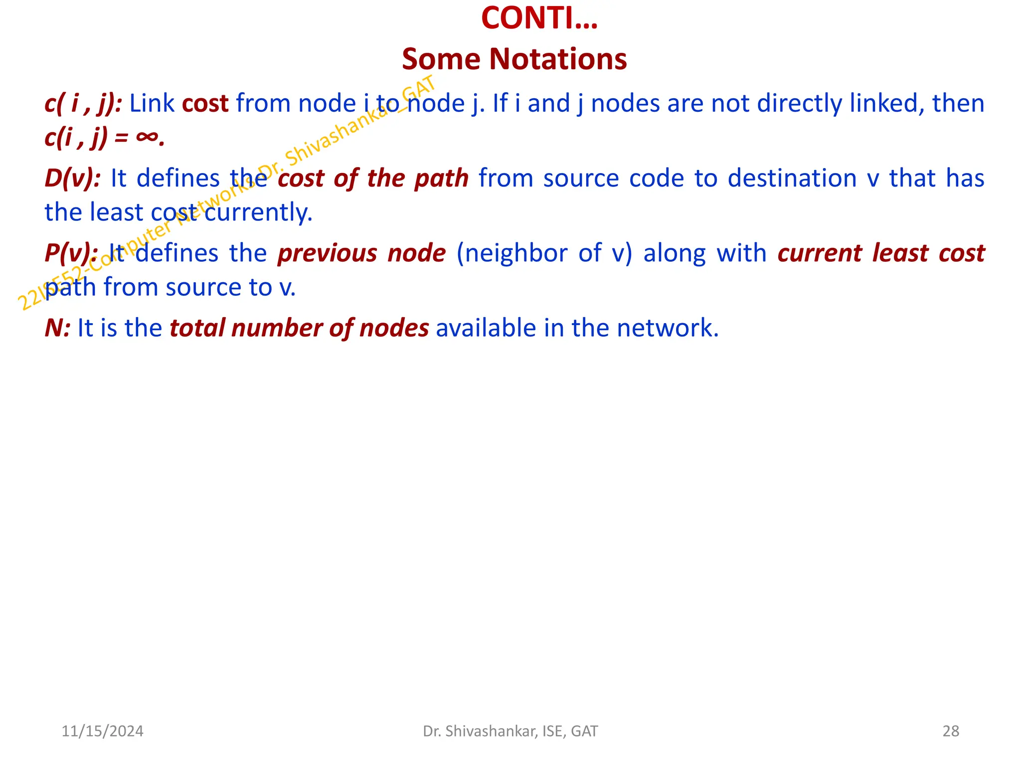
Some Notations
c( i, j): Link cost from node i to node j. If i and j nodes are not directly linked, then
c(i , j) = ∞.
D(v): It defines the cost of the path from source code to destination v that has
the least cost currently.
P(v): It defines the previous node (neighbor of v) along with current least cost
path from source to v.
N: It is the total number of nodes available in the network.
11/15/2024 28
Dr. Shivashankar, ISE, GAT
29.
CONTI…
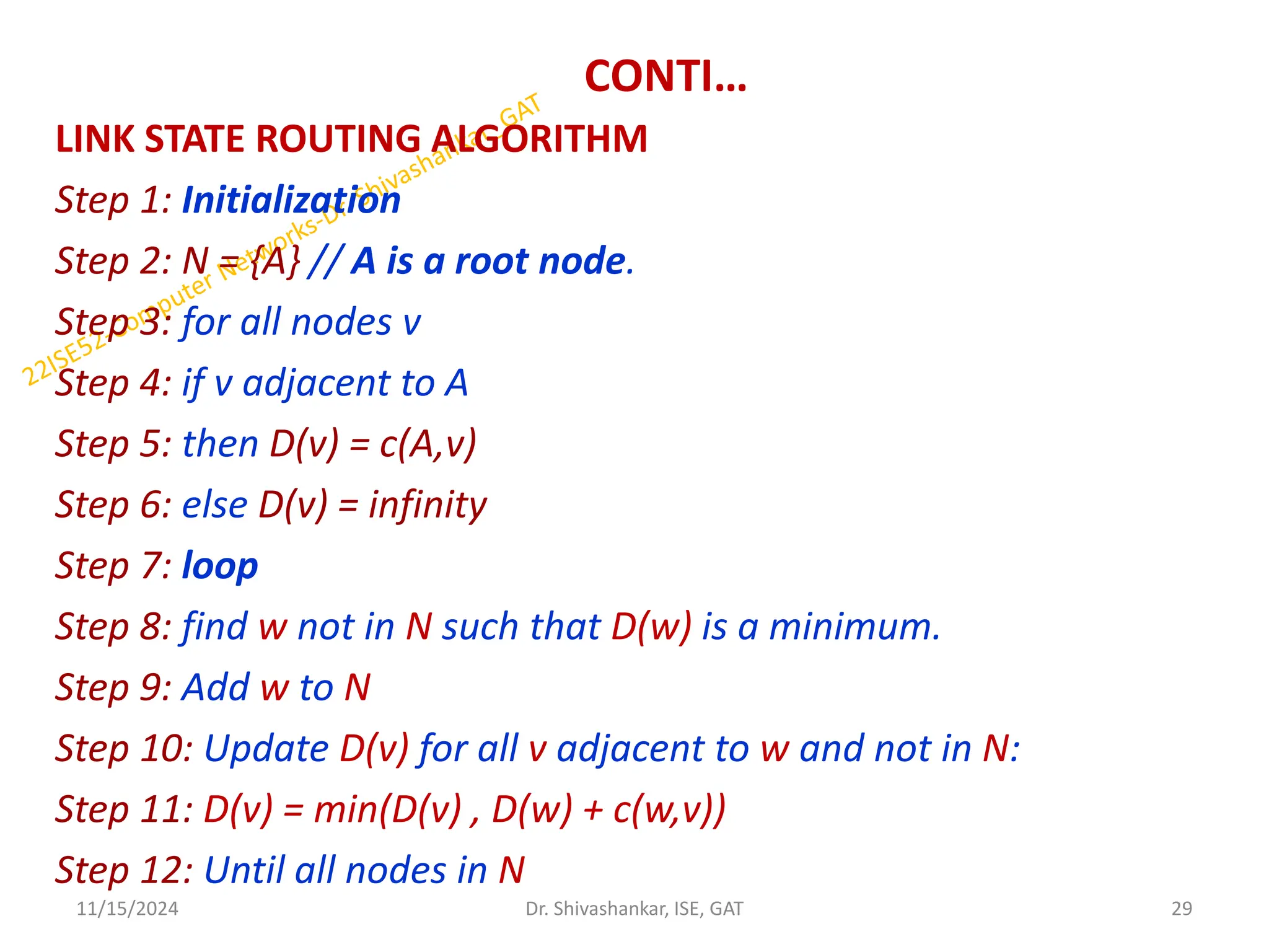
LINK STATE ROUTINGALGORITHM
Step 1: Initialization
Step 2: N = {A} // A is a root node.
Step 3: for all nodes v
Step 4: if v adjacent to A
Step 5: then D(v) = c(A,v)
Step 6: else D(v) = infinity
Step 7: loop
Step 8: find w not in N such that D(w) is a minimum.
Step 9: Add w to N
Step 10: Update D(v) for all v adjacent to w and not in N:
Step 11: D(v) = min(D(v) , D(w) + c(w,v))
Step 12: Until all nodes in N
11/15/2024 29
Dr. Shivashankar, ISE, GAT
30.
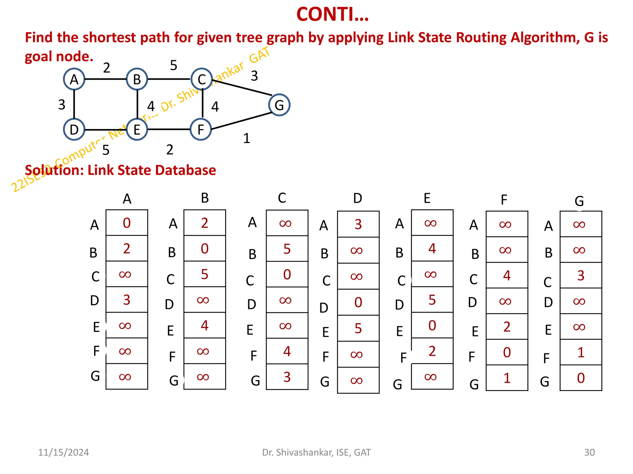
CONTI…
Find the shortestpath for given tree graph by applying Link State Routing Algorithm, G is
goal node.
Solution: Link State Database
11/15/2024 30
Dr. Shivashankar, ISE, GAT
A B
D F
E
C
G
3
2
4 4
5 2
5
3
1
0
2
∞
3
∞
∞
∞
A
A
B
C
D
E
F
G
2
0
5
∞
4
∞
∞
∞
5
0
∞
∞
4
3
3
∞
∞
0
5
∞
∞
∞
4
∞
5
0
2
∞
∞
∞
4
∞
2
0
1
∞
∞
3
∞
∞
1
0
B C D E F G
A
A
A A
A
A
B B B B B
C C C C C C
B
D D D D D D
E E E E E E
F F F F F F
G
G
G
G
G
G
31.
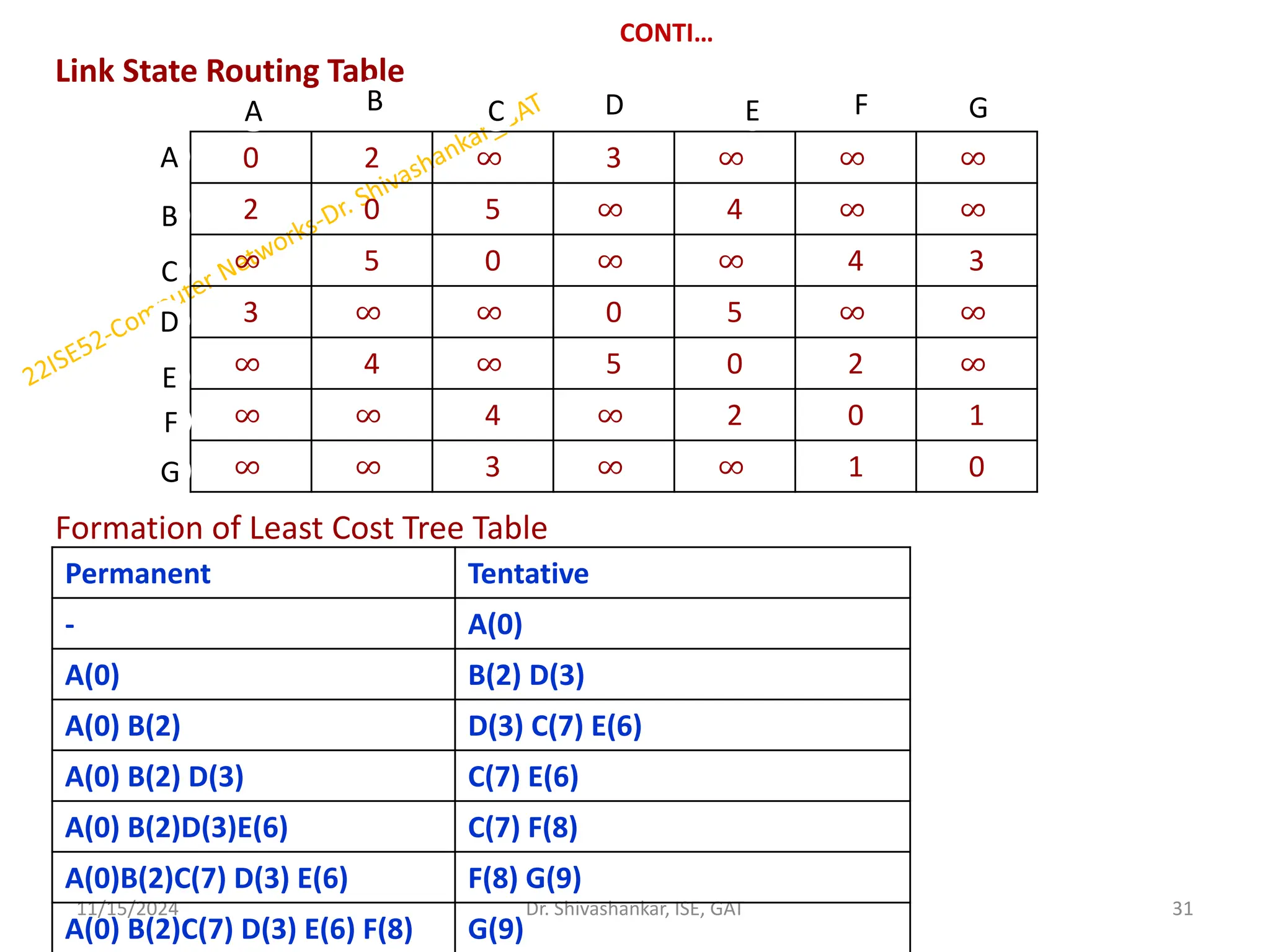
CONTI…
Link State RoutingTable
Formation of Least Cost Tree Table
11/15/2024 31
Dr. Shivashankar, ISE, GAT
0 2 ∞ 3 ∞ ∞ ∞
2 0 5 ∞ 4 ∞ ∞
∞ 5 0 ∞ ∞ 4 3
3 ∞ ∞ 0 5 ∞ ∞
∞ 4 ∞ 5 0 2 ∞
∞ ∞ 4 ∞ 2 0 1
∞ ∞ 3 ∞ ∞ 1 0
A
A
B
C
D
F
E
G
B C D E F G
Permanent Tentative
- A(0)
A(0) B(2) D(3)
A(0) B(2) D(3) C(7) E(6)
A(0) B(2) D(3) C(7) E(6)
A(0) B(2)D(3)E(6) C(7) F(8)
A(0)B(2)C(7) D(3) E(6) F(8) G(9)
A(0) B(2)C(7) D(3) E(6) F(8) G(9)
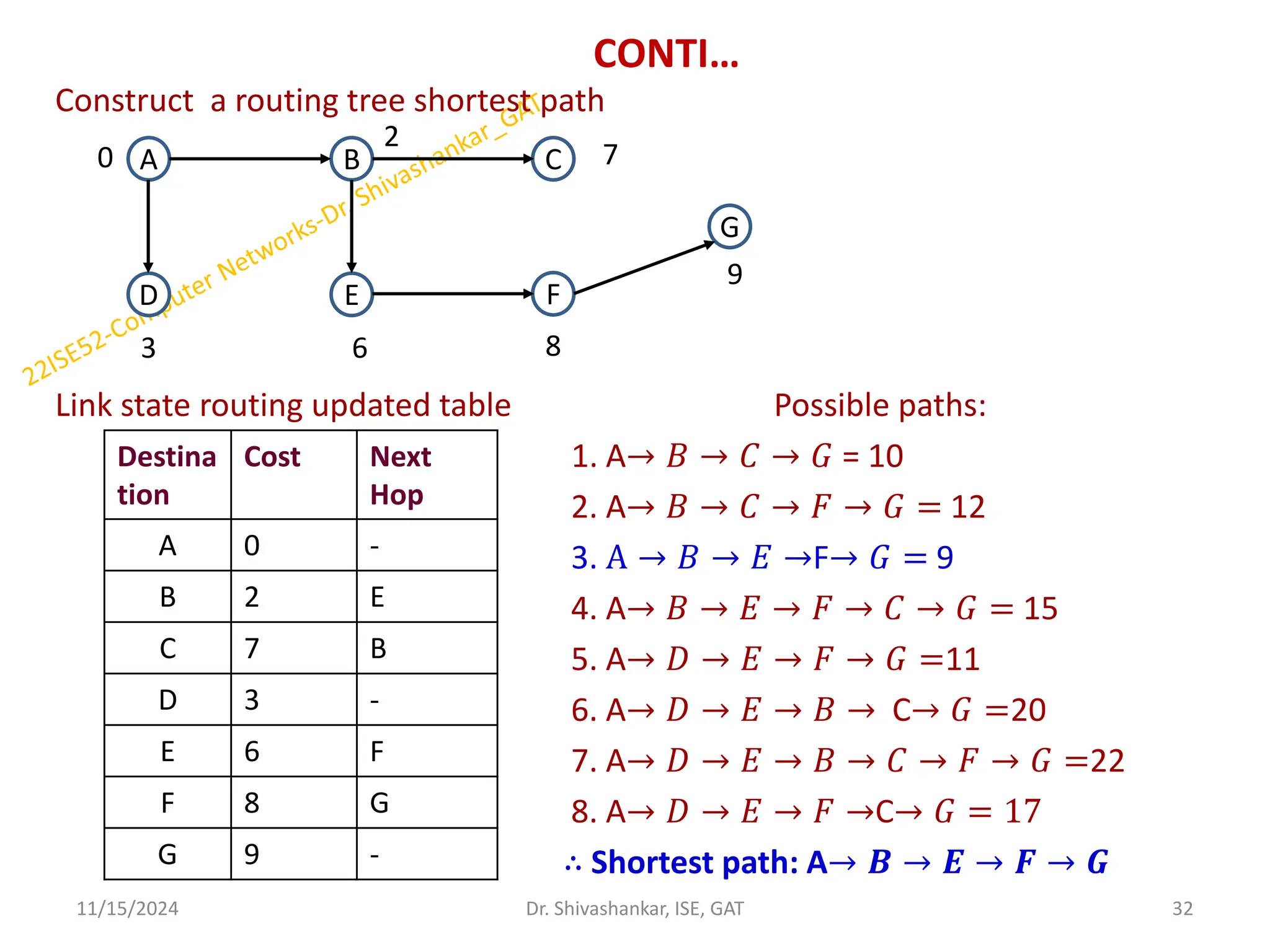
32.
CONTI…
Construct a routingtree shortest path
Link state routing updated table Possible paths:
1. A→ 𝐵 → 𝐶 → 𝐺 = 10
2. A→ 𝐵 → 𝐶 → 𝐹 → 𝐺 = 12
3. A → 𝐵 → 𝐸 →F→ 𝐺 = 9
4. A→ 𝐵 → 𝐸 → 𝐹 → 𝐶 → 𝐺 = 15
5. A→ 𝐷 → 𝐸 → 𝐹 → 𝐺 =11
6. A→ 𝐷 → 𝐸 → 𝐵 → C→ 𝐺 =20
7. A→ 𝐷 → 𝐸 → 𝐵 → 𝐶 → 𝐹 → 𝐺 =22
8. A→ 𝐷 → 𝐸 → 𝐹 →C→ 𝐺 = 17
∴ Shortest path: A→ 𝑩 → 𝑬 → 𝑭 → 𝑮
11/15/2024 32
Dr. Shivashankar, ISE, GAT
A B C
D F
E
G
0
2
3
9
8
7
6
Destina
tion
Cost Next
Hop
A 0 -
B 2 E
C 7 B
D 3 -
E 6 F
F 8 G
G 9 -
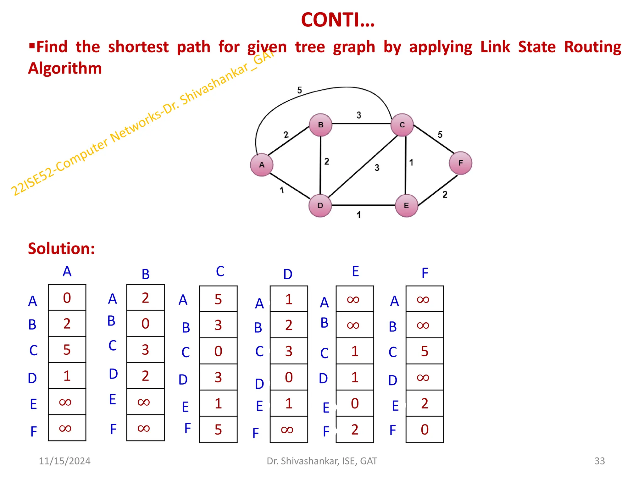
33.
CONTI…
Find the shortestpath for given tree graph by applying Link State Routing
Algorithm
Solution:
11/15/2024 33
Dr. Shivashankar, ISE, GAT
0
2
5
1
∞
∞
A
A
F
E
D
C
B
2
0
3
2
∞
∞
5
3
0
3
1
5
1
2
3
0
1
∞
∞
∞
1
1
0
2
∞
∞
5
∞
2
0
B C D E F
A
B
C
D
E
F
A
B
C
D
E
F F
E
A
B
C
D
E
A
B
C
D
F
A
B
C
D
E
F
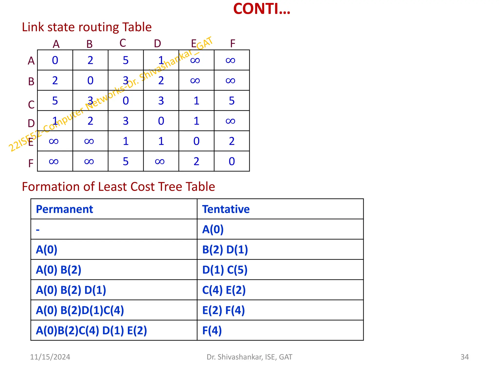
34.
CONTI…
Link state routingTable
Formation of Least Cost Tree Table
11/15/2024 34
Dr. Shivashankar, ISE, GAT
0 2 5 1 ∞ ∞
2 0 3 2 ∞ ∞
5 3 0 3 1 5
1 2 3 0 1 ∞
∞ ∞ 1 1 0 2
∞ ∞ 5 ∞ 2 0
A B
A
B
C
E
D
F
F
E
D
C
Permanent Tentative
- A(0)
A(0) B(2) D(1)
A(0) B(2) D(1) C(5)
A(0) B(2) D(1) C(4) E(2)
A(0) B(2)D(1)C(4) E(2) F(4)
A(0)B(2)C(4) D(1) E(2) F(4)
35.
CONTI…
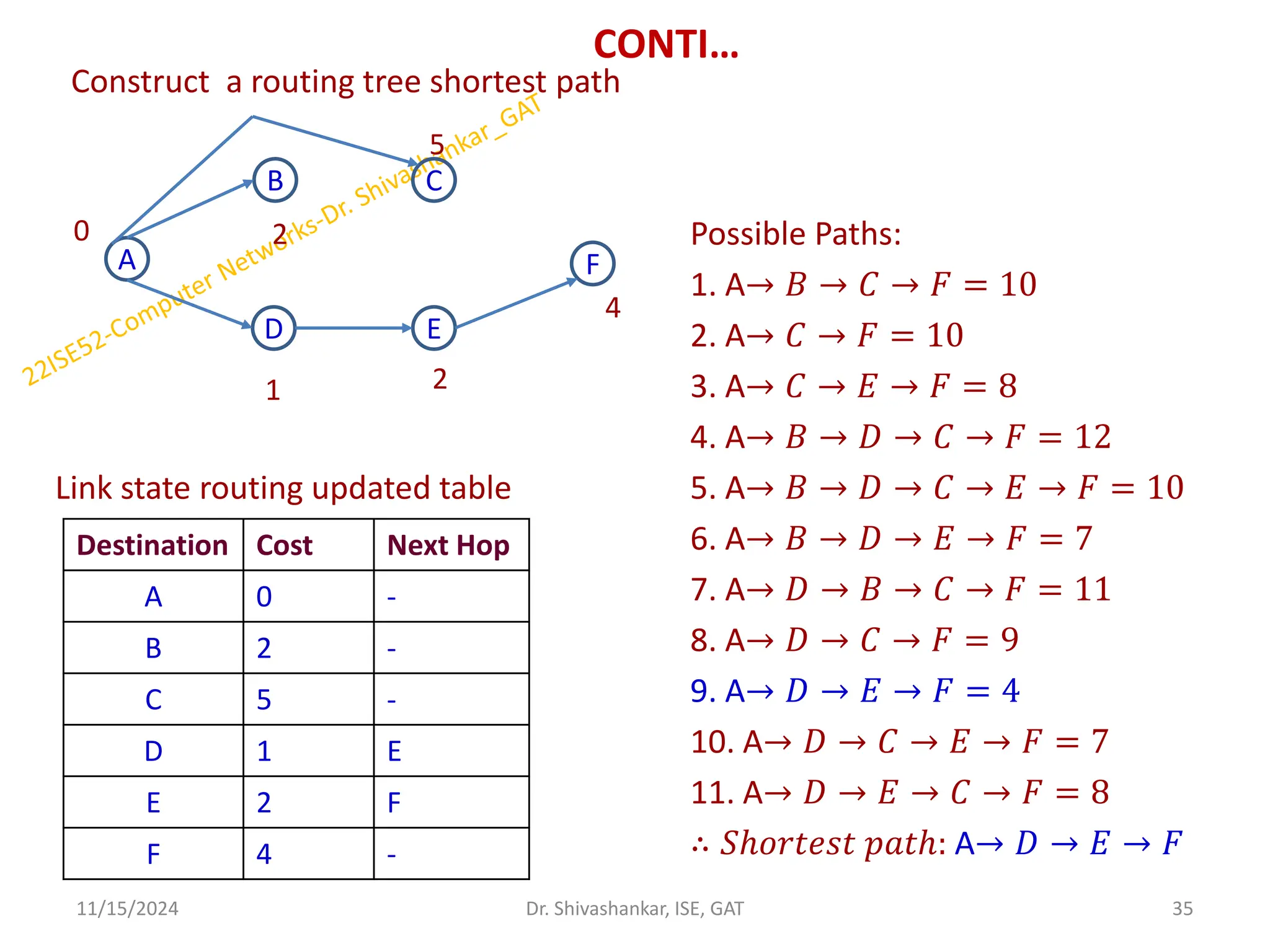
Construct a routingtree shortest path
Possible Paths:
1. A→ 𝐵 → 𝐶 → 𝐹 = 10
2. A→ 𝐶 → 𝐹 = 10
3. A→ 𝐶 → 𝐸 → 𝐹 = 8
4. A→ 𝐵 → 𝐷 → 𝐶 → 𝐹 = 12
Link state routing updated table 5. A→ 𝐵 → 𝐷 → 𝐶 → 𝐸 → 𝐹 = 10
6. A→ 𝐵 → 𝐷 → 𝐸 → 𝐹 = 7
7. A→ 𝐷 → 𝐵 → 𝐶 → 𝐹 = 11
8. A→ 𝐷 → 𝐶 → 𝐹 = 9
9. A→ 𝐷 → 𝐸 → 𝐹 = 4
10. A→ 𝐷 → 𝐶 → 𝐸 → 𝐹 = 7
11. A→ 𝐷 → 𝐸 → 𝐶 → 𝐹 = 8
∴ 𝑆ℎ𝑜𝑟𝑡𝑒𝑠𝑡 𝑝𝑎𝑡ℎ: A→ 𝐷 → 𝐸 → 𝐹
11/15/2024 35
Dr. Shivashankar, ISE, GAT
A
B C
F
D E
0 2
5
2
1
4
Destination Cost Next Hop
A 0 -
B 2 -
C 5 -
D 1 E
E 2 F
F 4 -
36.
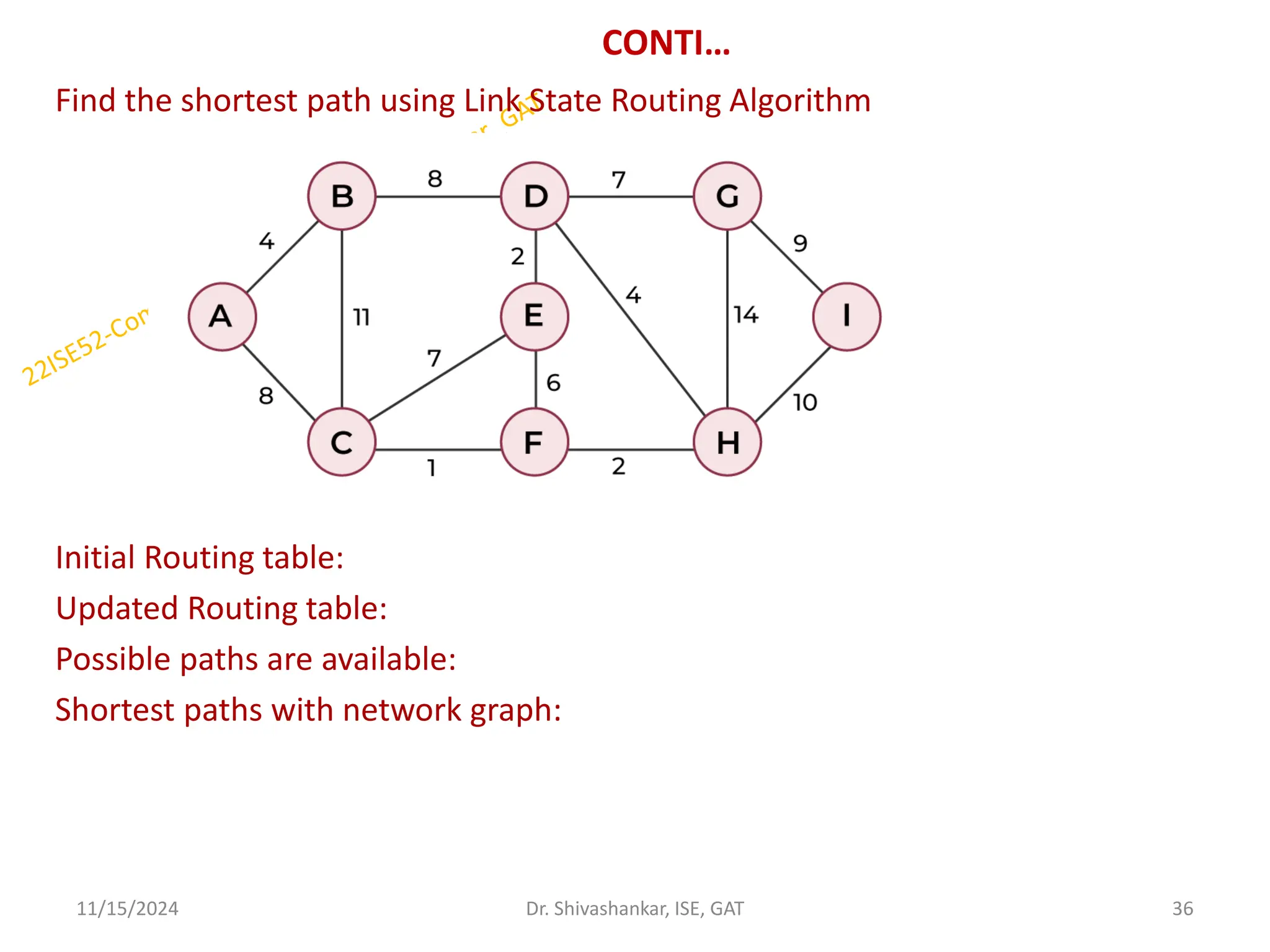
CONTI…
Find the shortestpath using Link State Routing Algorithm
Initial Routing table:
Updated Routing table:
Possible paths are available:
Shortest paths with network graph:
11/15/2024 36
Dr. Shivashankar, ISE, GAT
37.
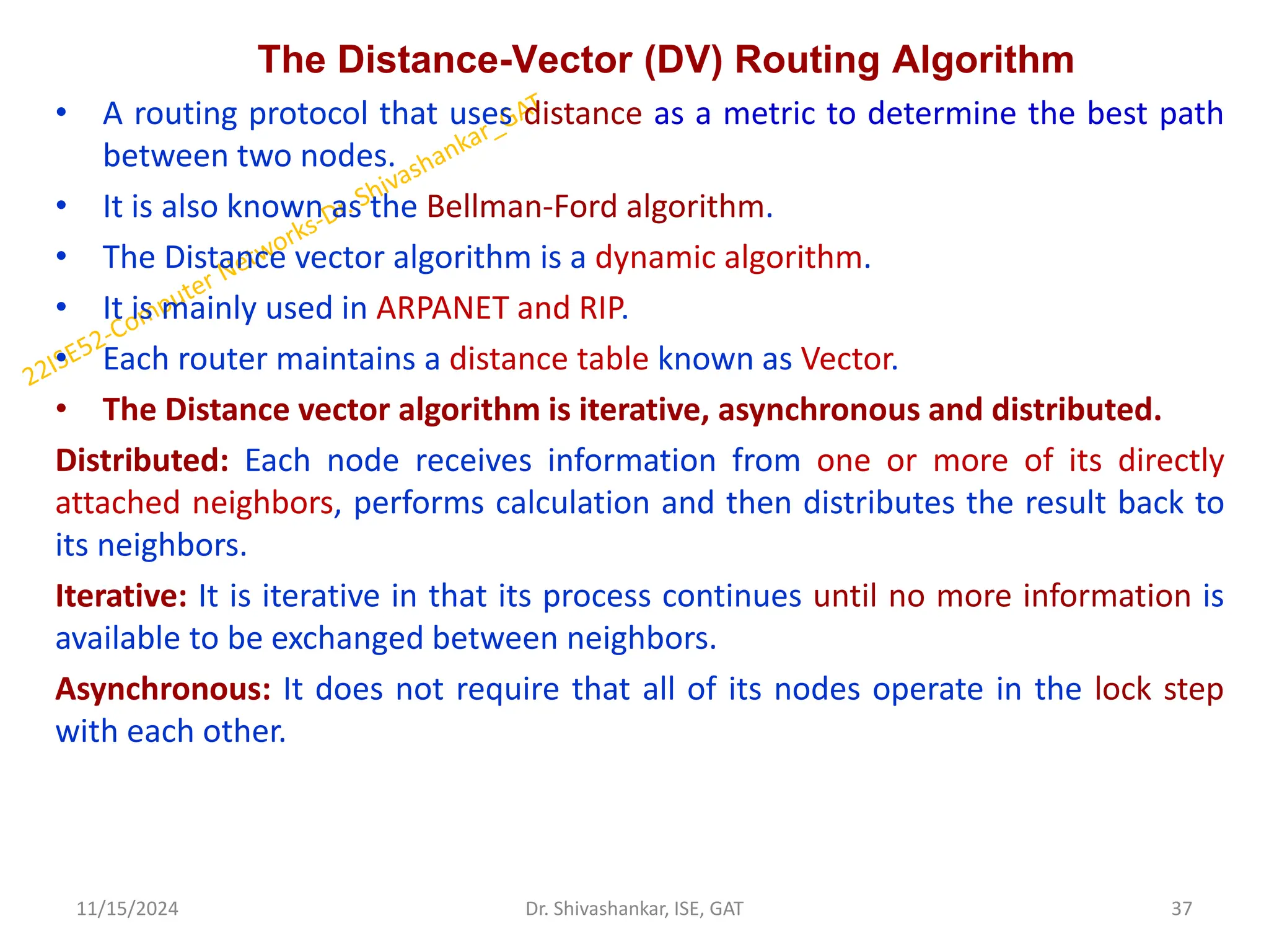
The Distance-Vector (DV)Routing Algorithm
• A routing protocol that uses distance as a metric to determine the best path
between two nodes.
• It is also known as the Bellman-Ford algorithm.
• The Distance vector algorithm is a dynamic algorithm.
• It is mainly used in ARPANET and RIP.
• Each router maintains a distance table known as Vector.
• The Distance vector algorithm is iterative, asynchronous and distributed.
Distributed: Each node receives information from one or more of its directly
attached neighbors, performs calculation and then distributes the result back to
its neighbors.
Iterative: It is iterative in that its process continues until no more information is
available to be exchanged between neighbors.
Asynchronous: It does not require that all of its nodes operate in the lock step
with each other.
11/15/2024 37
Dr. Shivashankar, ISE, GAT
38.
CONTI…
Let dx(y) bethe cost of the least-cost path from node x to node y. The least costs
are related by Bellman-Ford equation,
dx(y) = minv{c(x,v) + dv(y)}
Where the 𝒎𝒊𝒏𝒗 is the equation taken for all x neighbors.
After traveling from x to v, if we consider the least-cost path from v to y, the path
cost will be c(x,v)+dv(y).
The least cost from x to y is the minimum of c(x,v)+dv(y) taken over all neighbors.
With the Distance Vector Routing algorithm, the node x contains the following
routing information:
For each neighbor v, the cost c(x,v) is the path cost from x to directly attached
neighbor, v.
The distance vector x, i.e., Dx = [ Dx(y) : y in N ], containing its cost to all
destinations, y, in N.
The distance vector of each of its neighbors, i.e., Dv = [ Dv(y) : y in N ] for each
neighbor v of x.
11/15/2024 38
Dr. Shivashankar, ISE, GAT
39.
Algorithm
At each nodex,
Initialization
Step 1: for all destinations y in N:
Step 2: Dx(y) = c(x,y) // If y is not a neighbor then c(x,y) = ∞
Step 3: for each neighbor w
Step 4: Dw(y) = ? for all destination y in N.
Step 5: for each neighbor w
Step 6: send distance vector Dx = [ Dx(y) : y in N ] to w
Step 7: loop
Step 9: wait(until I receive any distance vector from some neighbor w)
Step 10: for each y in N:
Step 11: Dx(y) = minv{c(x,v)+Dv(y)}
Step 12: If Dx(y) is changed for any destination y
Step 13: Send distance vector Dx = [ Dx(y) : y in N ] to all neighbors
Step 14: forever
11/15/2024 39
Dr. Shivashankar, ISE, GAT
40.
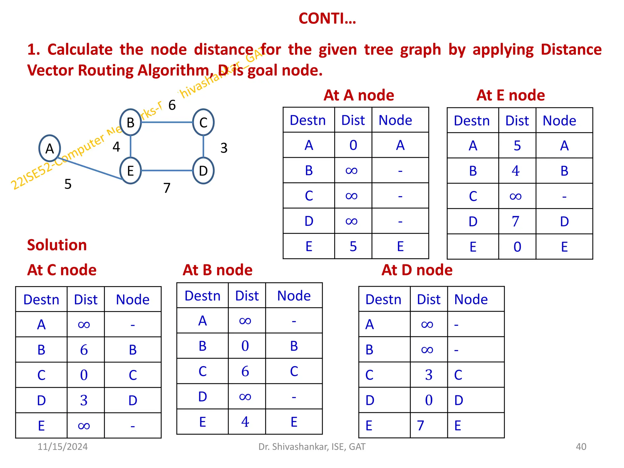
CONTI…
1. Calculate thenode distance for the given tree graph by applying Distance
Vector Routing Algorithm, D is goal node.
At A node At E node
Solution
At C node At B node At D node
11/15/2024 40
Dr. Shivashankar, ISE, GAT
A
B C
D
E
5
4
7
3
6
Destn Dist Node
A 0 A
B ∞ -
C ∞ -
D ∞ -
E 5 E
Destn Dist Node
A 5 A
B 4 B
C ∞ -
D 7 D
E 0 E
Destn Dist Node
A ∞ -
B 6 B
C 0 C
D 3 D
E ∞ -
Destn Dist Node
A ∞ -
B 0 B
C 6 C
D ∞ -
E 4 E
Destn Dist Node
A ∞ -
B ∞ -
C 3 C
D 0 D
E 7 E
41.
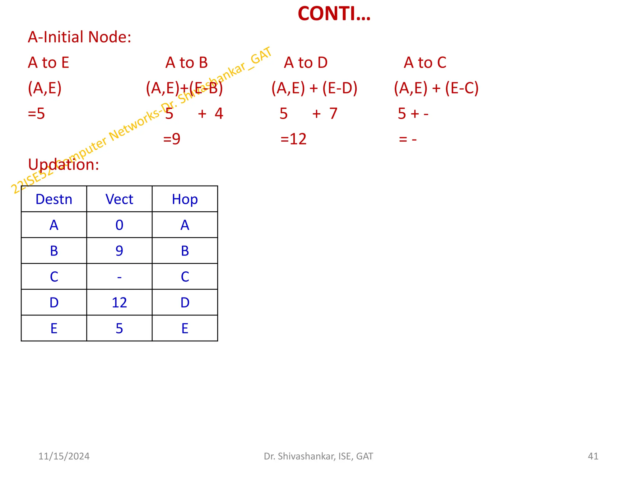
CONTI…
A-Initial Node:
A toE A to B A to D A to C
(A,E) (A,E)+(E-B) (A,E) + (E-D) (A,E) + (E-C)
=5 5 + 4 5 + 7 5 + -
=9 =12 = -
Updation:
11/15/2024 41
Dr. Shivashankar, ISE, GAT
Destn Vect Hop
A 0 A
B 9 B
C - C
D 12 D
E 5 E
42.
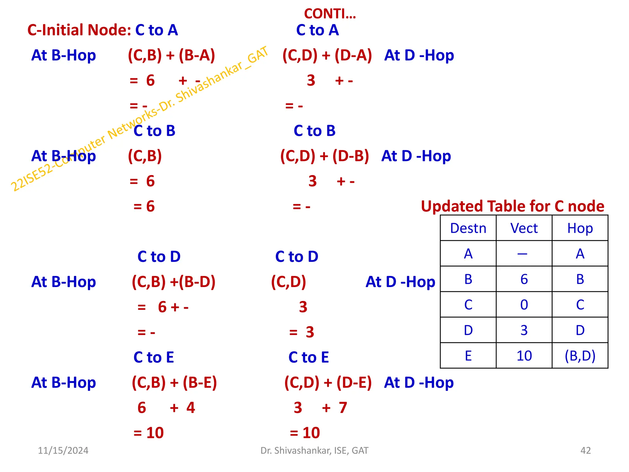
CONTI…
C-Initial Node: Cto A C to A
At B-Hop (C,B) + (B-A) (C,D) + (D-A) At D -Hop
= 6 + - 3 + -
= - = -
C to B C to B
At B-Hop (C,B) (C,D) + (D-B) At D -Hop
= 6 3 + -
= 6 = - Updated Table for C node
C to D C to D
At B-Hop (C,B) +(B-D) (C,D) At D -Hop
= 6 + - 3
= - = 3
C to E C to E
At B-Hop (C,B) + (B-E) (C,D) + (D-E) At D -Hop
6 + 4 3 + 7
= 10 = 10
11/15/2024 42
Dr. Shivashankar, ISE, GAT
Destn Vect Hop
A − A
B 6 B
C 0 C
D 3 D
E 10 (B,D)
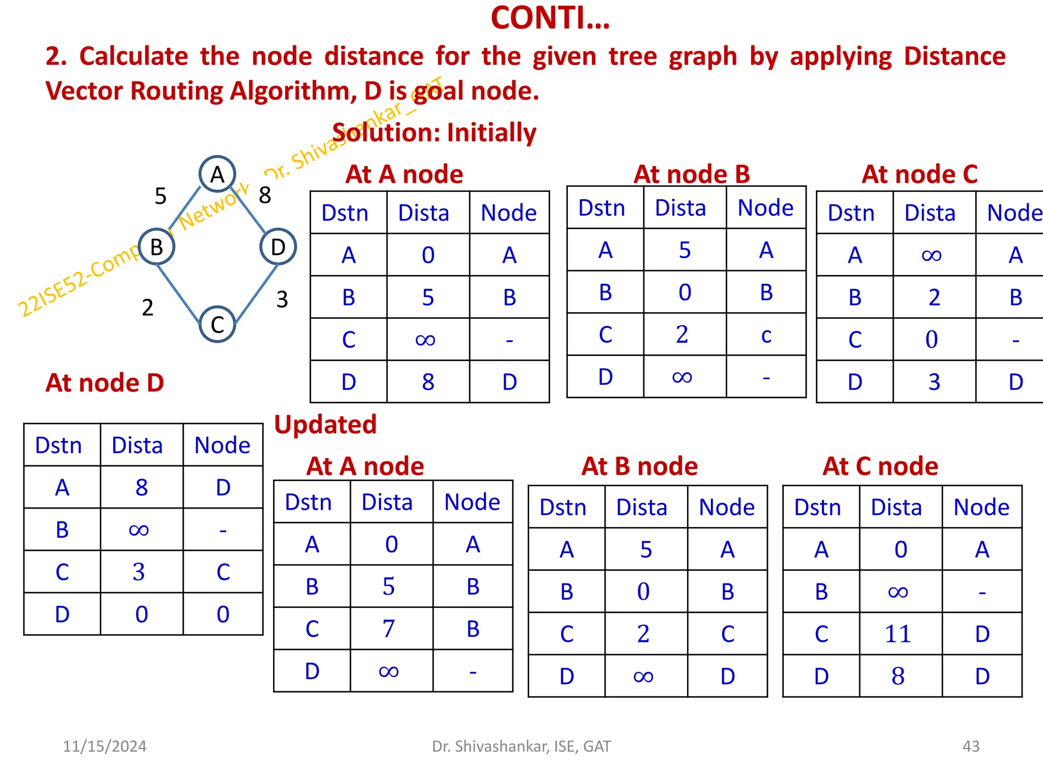
43.
CONTI…
2. Calculate thenode distance for the given tree graph by applying Distance
Vector Routing Algorithm, D is goal node.
Solution: Initially
At A node At node B At node C
At node D
Updated
At A node At B node At C node
11/15/2024 43
Dr. Shivashankar, ISE, GAT
A
B D
C
5
2 3
8
Dstn Dista Node
A 0 A
B 5 B
C ∞ -
D 8 D
Dstn Dista Node
A 5 A
B 0 B
C 2 c
D ∞ -
Dstn Dista Node
A ∞ A
B 2 B
C 0 -
D 3 D
Dstn Dista Node
A 8 D
B ∞ -
C 3 C
D 0 0
Dstn Dista Node
A 0 A
B 5 B
C 7 B
D ∞ -
Dstn Dista Node
A 5 A
B 0 B
C 2 C
D ∞ D
Dstn Dista Node
A 0 A
B ∞ -
C 11 D
D 8 D
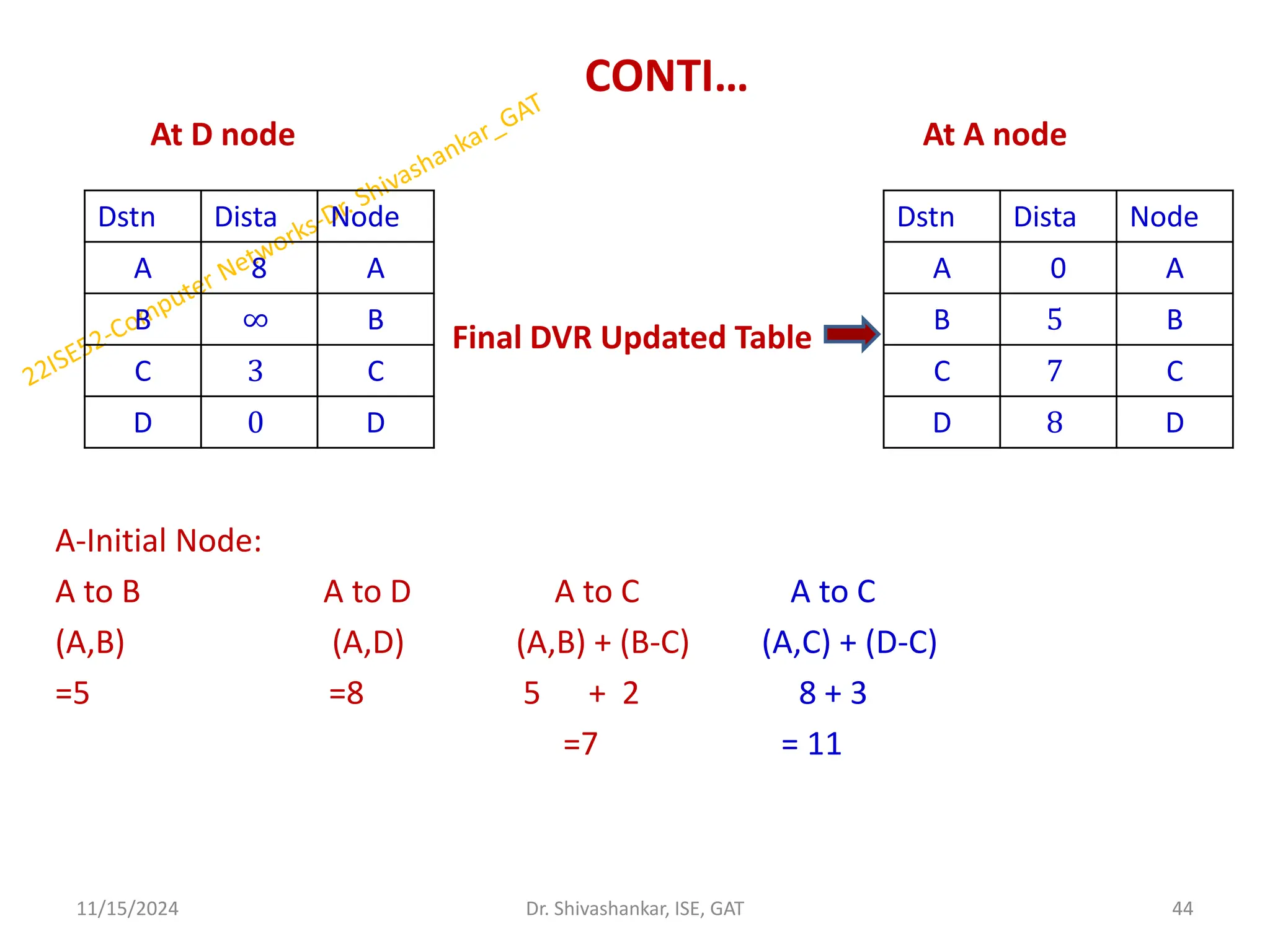
44.
CONTI…
At D nodeAt A node
Final DVR Updated Table
A-Initial Node:
A to B A to D A to C A to C
(A,B) (A,D) (A,B) + (B-C) (A,C) + (D-C)
=5 =8 5 + 2 8 + 3
=7 = 11
11/15/2024 44
Dr. Shivashankar, ISE, GAT
Dstn Dista Node
A 8 A
B ∞ B
C 3 C
D 0 D
Dstn Dista Node
A 0 A
B 5 B
C 7 C
D 8 D
45.
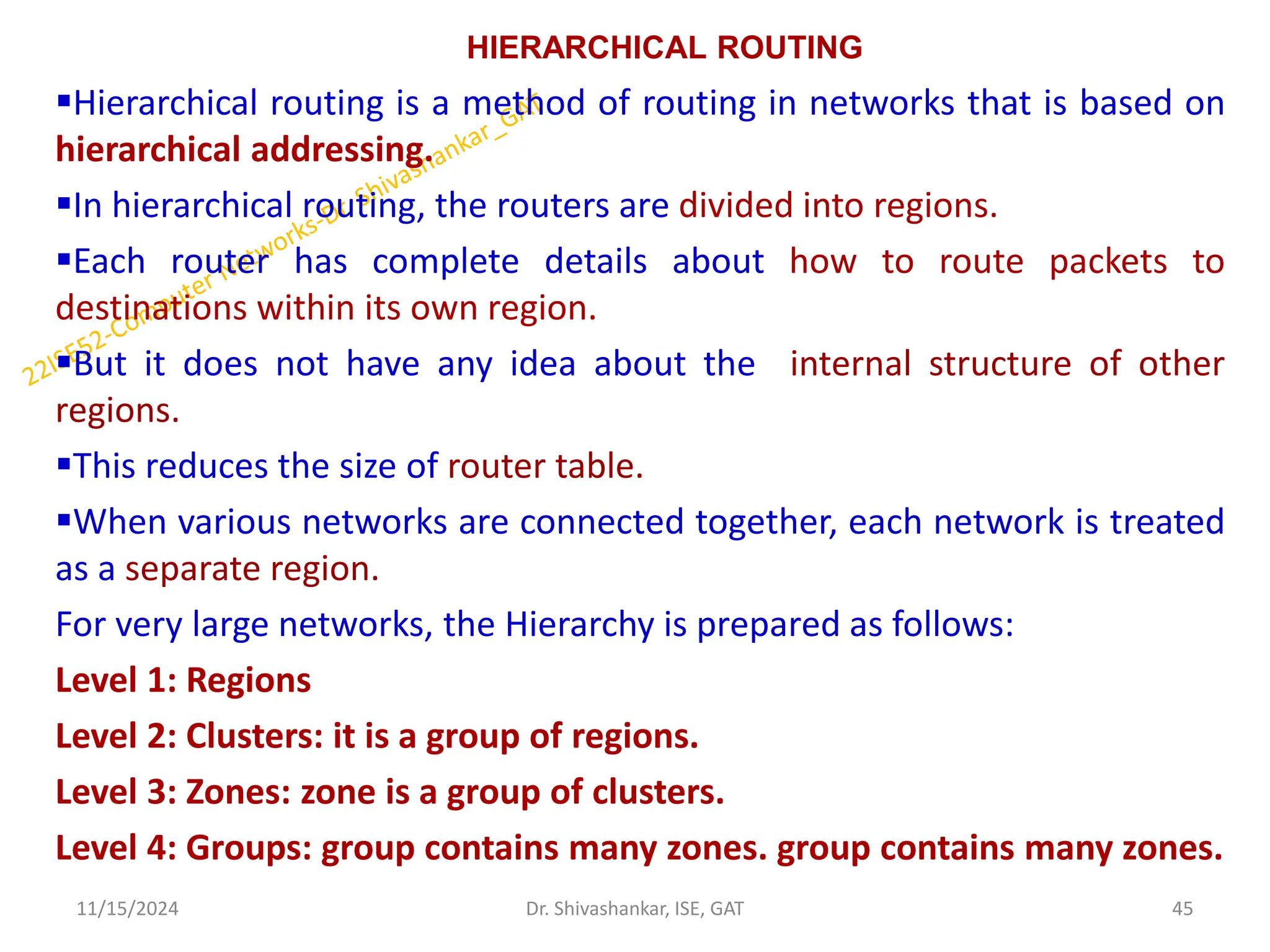
HIERARCHICAL ROUTING
Hierarchical routingis a method of routing in networks that is based on
hierarchical addressing.
In hierarchical routing, the routers are divided into regions.
Each router has complete details about how to route packets to
destinations within its own region.
But it does not have any idea about the internal structure of other
regions.
This reduces the size of router table.
When various networks are connected together, each network is treated
as a separate region.
For very large networks, the Hierarchy is prepared as follows:
Level 1: Regions
Level 2: Clusters: it is a group of regions.
Level 3: Zones: zone is a group of clusters.
Level 4: Groups: group contains many zones. group contains many zones.
11/15/2024 45
Dr. Shivashankar, ISE, GAT
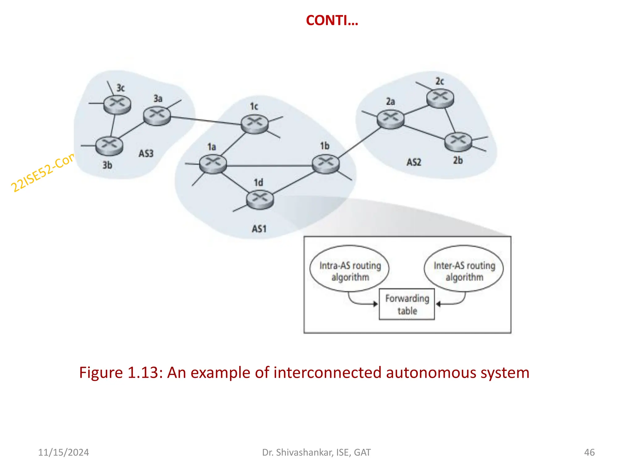
46.
CONTI…
Figure 1.13: Anexample of interconnected autonomous system
11/15/2024 46
Dr. Shivashankar, ISE, GAT
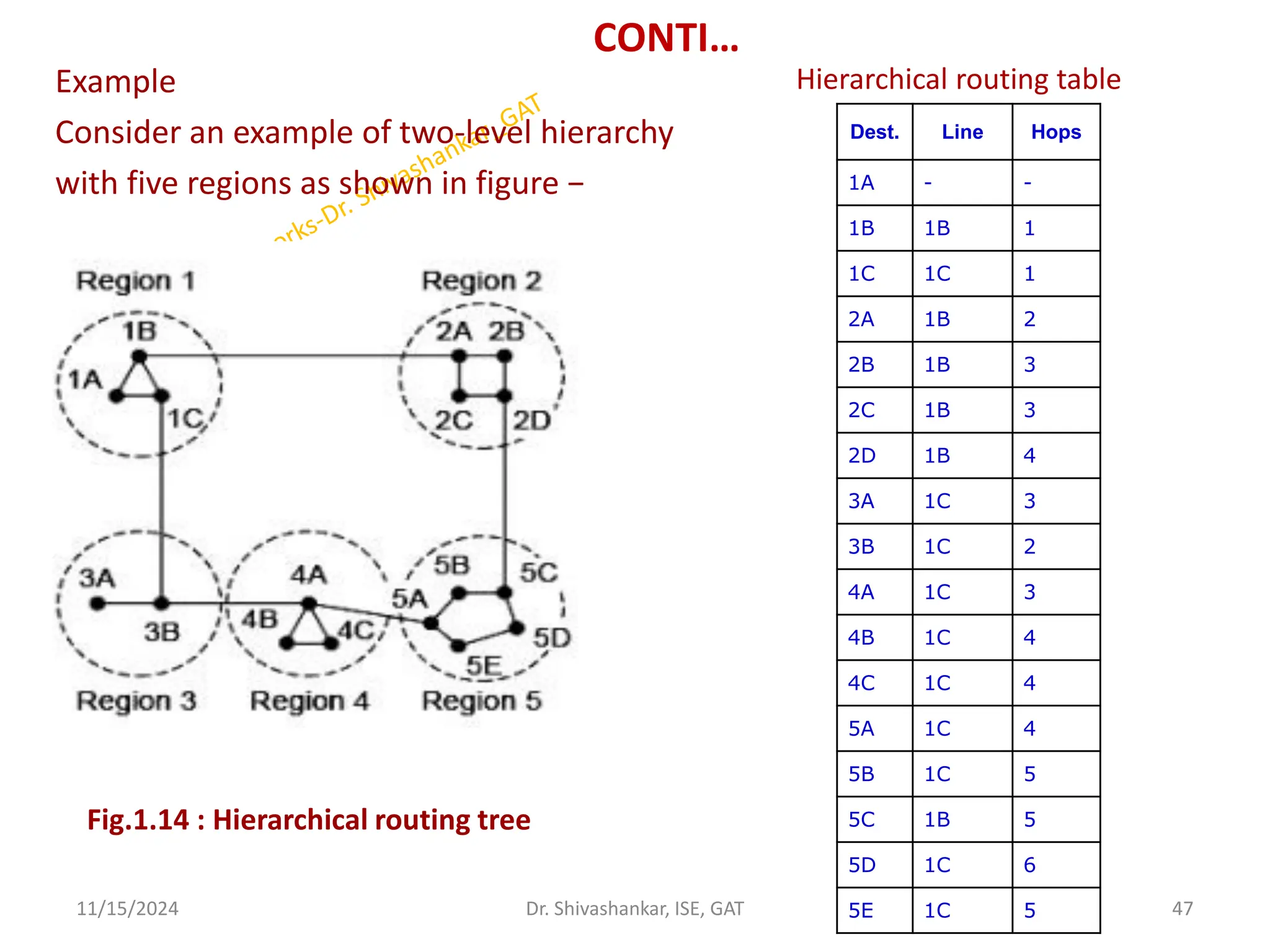
47.
CONTI…
Example
Consider an exampleof two-level hierarchy
with five regions as shown in figure −
11/15/2024 47
Dr. Shivashankar, ISE, GAT
Dest. Line Hops
1A - -
1B 1B 1
1C 1C 1
2A 1B 2
2B 1B 3
2C 1B 3
2D 1B 4
3A 1C 3
3B 1C 2
4A 1C 3
4B 1C 4
4C 1C 4
5A 1C 4
5B 1C 5
5C 1B 5
5D 1C 6
5E 1C 5
Fig.1.14 : Hierarchical routing tree
Hierarchical routing table
48.
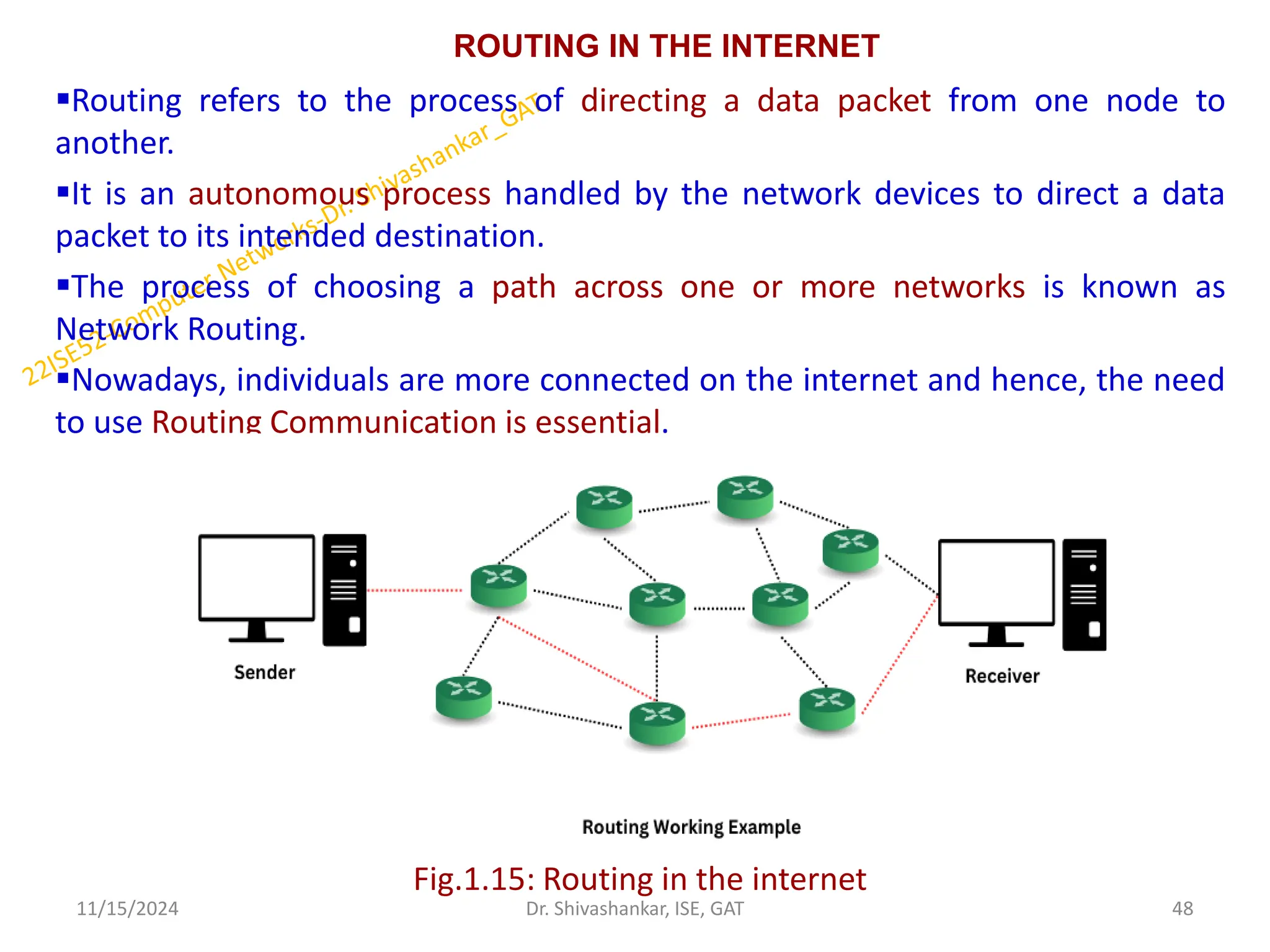
ROUTING IN THEINTERNET
Routing refers to the process of directing a data packet from one node to
another.
It is an autonomous process handled by the network devices to direct a data
packet to its intended destination.
The process of choosing a path across one or more networks is known as
Network Routing.
Nowadays, individuals are more connected on the internet and hence, the need
to use Routing Communication is essential.
Fig.1.15: Routing in the internet
11/15/2024 48
Dr. Shivashankar, ISE, GAT
49.
CONTI…
Intra-AS Routing inthe Internet
• It is the process of routing information within a single
Autonomous System(AS).
• An AS is an independently operated network, such as a campus
network, internet service provider, or content provider.
• It is used to determine how routing is performed within an
autonomous system (AS).
• Intra-AS routing protocols are also known as interior gateway
protocols.
• Two routing protocols have been used extensively for routing
within an autonomous system in the Internet:
1. Routing Information Protocol (RIP)
2. Open Shortest Path First (OSPF).
11/15/2024 49
Dr. Shivashankar, ISE, GAT
50.
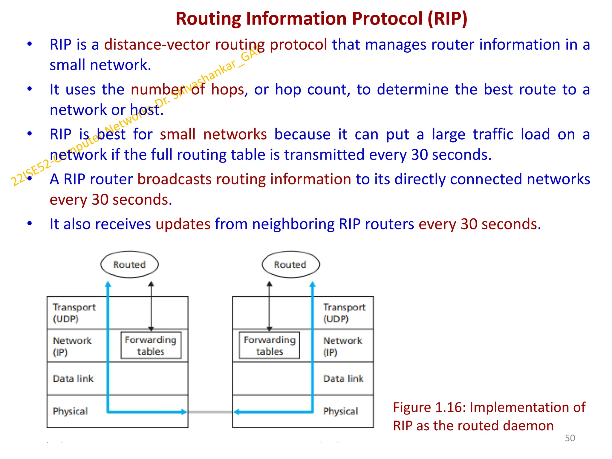
Routing Information Protocol(RIP)
• RIP is a distance-vector routing protocol that manages router information in a
small network.
• It uses the number of hops, or hop count, to determine the best route to a
network or host.
• RIP is best for small networks because it can put a large traffic load on a
network if the full routing table is transmitted every 30 seconds.
• A RIP router broadcasts routing information to its directly connected networks
every 30 seconds.
• It also receives updates from neighboring RIP routers every 30 seconds.
11/15/2024 50
Dr. Shivashankar, ISE, GAT
Figure 1.16: Implementation of
RIP as the routed daemon
51.
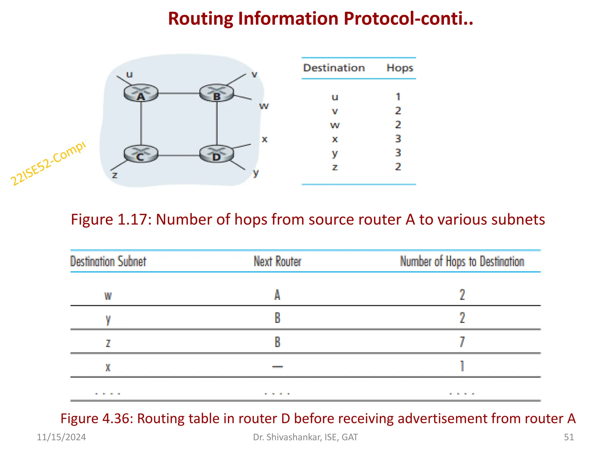
Routing Information Protocol-conti..
Figure1.17: Number of hops from source router A to various subnets
11/15/2024 51
Dr. Shivashankar, ISE, GAT
Figure 4.36: Routing table in router D before receiving advertisement from router A
52.
CONTI…
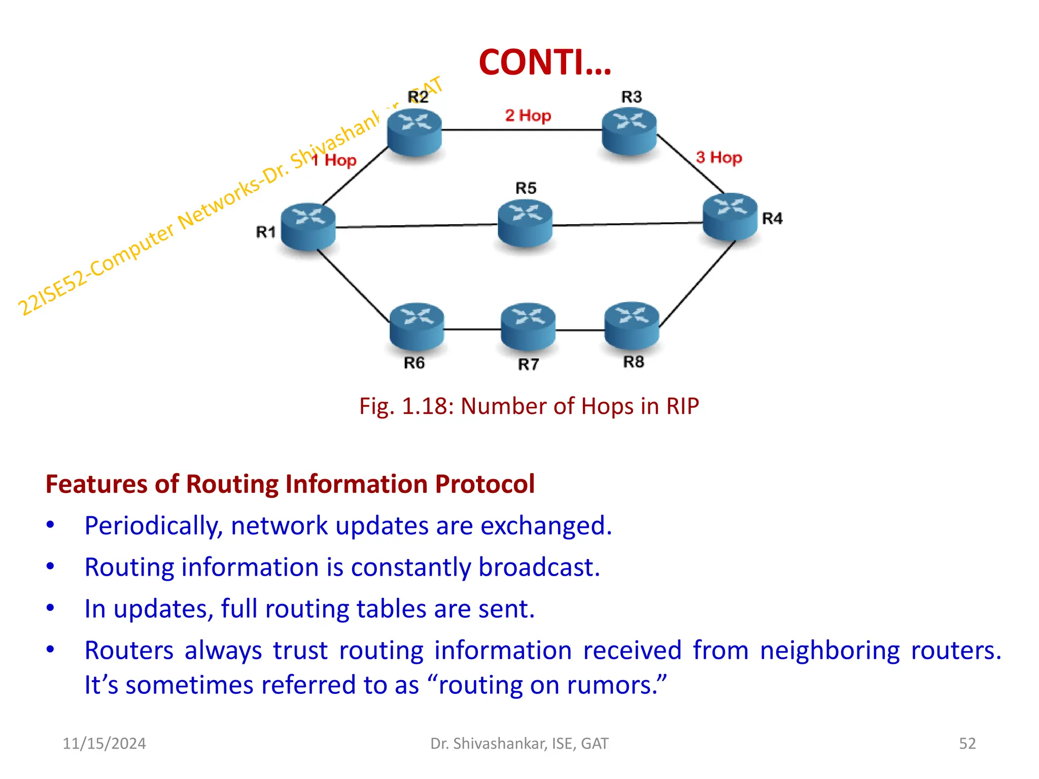
Features of RoutingInformation Protocol
• Periodically, network updates are exchanged.
• Routing information is constantly broadcast.
• In updates, full routing tables are sent.
• Routers always trust routing information received from neighboring routers.
It’s sometimes referred to as “routing on rumors.”
11/15/2024 52
Dr. Shivashankar, ISE, GAT
Fig. 1.18: Number of Hops in RIP
53.
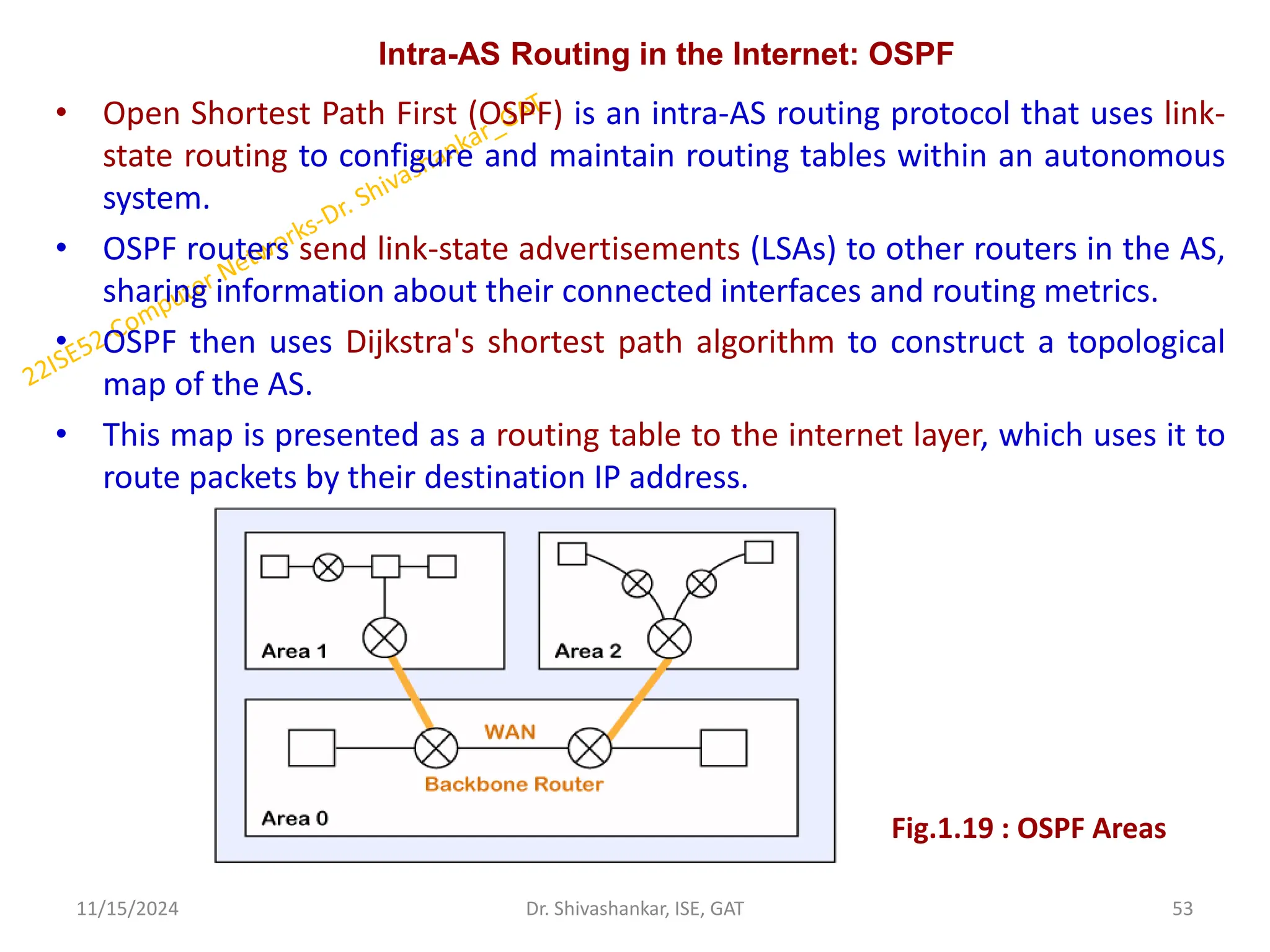
Intra-AS Routing inthe Internet: OSPF
• Open Shortest Path First (OSPF) is an intra-AS routing protocol that uses link-
state routing to configure and maintain routing tables within an autonomous
system.
• OSPF routers send link-state advertisements (LSAs) to other routers in the AS,
sharing information about their connected interfaces and routing metrics.
• OSPF then uses Dijkstra's shortest path algorithm to construct a topological
map of the AS.
• This map is presented as a routing table to the internet layer, which uses it to
route packets by their destination IP address.
11/15/2024 53
Dr. Shivashankar, ISE, GAT
Fig.1.19 : OSPF Areas
54.
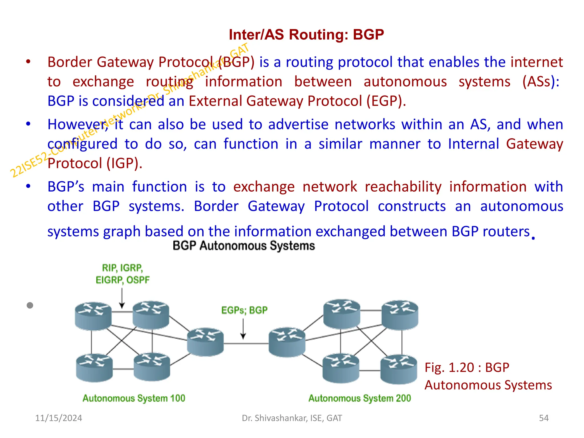
Inter/AS Routing: BGP
•Border Gateway Protocol (BGP) is a routing protocol that enables the internet
to exchange routing information between autonomous systems (ASs):
BGP is considered an External Gateway Protocol (EGP).
• However, it can also be used to advertise networks within an AS, and when
configured to do so, can function in a similar manner to Internal Gateway
Protocol (IGP).
• BGP’s main function is to exchange network reachability information with
other BGP systems. Border Gateway Protocol constructs an autonomous
systems graph based on the information exchanged between BGP routers.
•
11/15/2024 54
Dr. Shivashankar, ISE, GAT
Fig. 1.20 : BGP
Autonomous Systems
55.
Conti.
Characteristics of BorderGateway Protocol (BGP)
• Inter-Autonomous System Configuration: The main role of BGP is to provide
communication between two autonomous systems.
• BGP supports the Next-Hop Paradigm.
• Coordination among multiple BGP speakers within the AS.
• Path Information: BGP advertisements also include path information, along
with the reachable destination and next destination pair.
• Policy Support: BGP can implement policies that can be configured by the
administrator. For ex:- a router running BGP can be configured to distinguish
between the routes that are known within the AS and that which are known
from outside the AS.
• Runs Over TCP.
• BGP conserves network Bandwidth.
• BGP supports CIDR.
• BGP also supports Security.
11/15/2024 55
Dr. Shivashankar, ISE, GAT
56.
Conti..
Importance of BorderGateway Protocol
Security:
BGP is highly secure because it authenticates messages between routers using
preconfigured passwords through which unauthorized traffic is filtered out.
Scalability:
BGP is more scalable because it manages a vast number of routes and networks
present on the internet.
Supports Multihoming:
BGP allows multihoming means an organization can connect to multiple networks
simultaneously.
Calculate the Best Path:
As we know data packets is traveled across the internet from source to
destination every system in between the source and destination has to decide
where the data packet should go next
TCP/IP Model:
BGP is based on the TCP/IP model and it is used to control the network layer by
using transport layer protocol.
11/15/2024 56
Dr. Shivashankar, ISE, GAT
57.
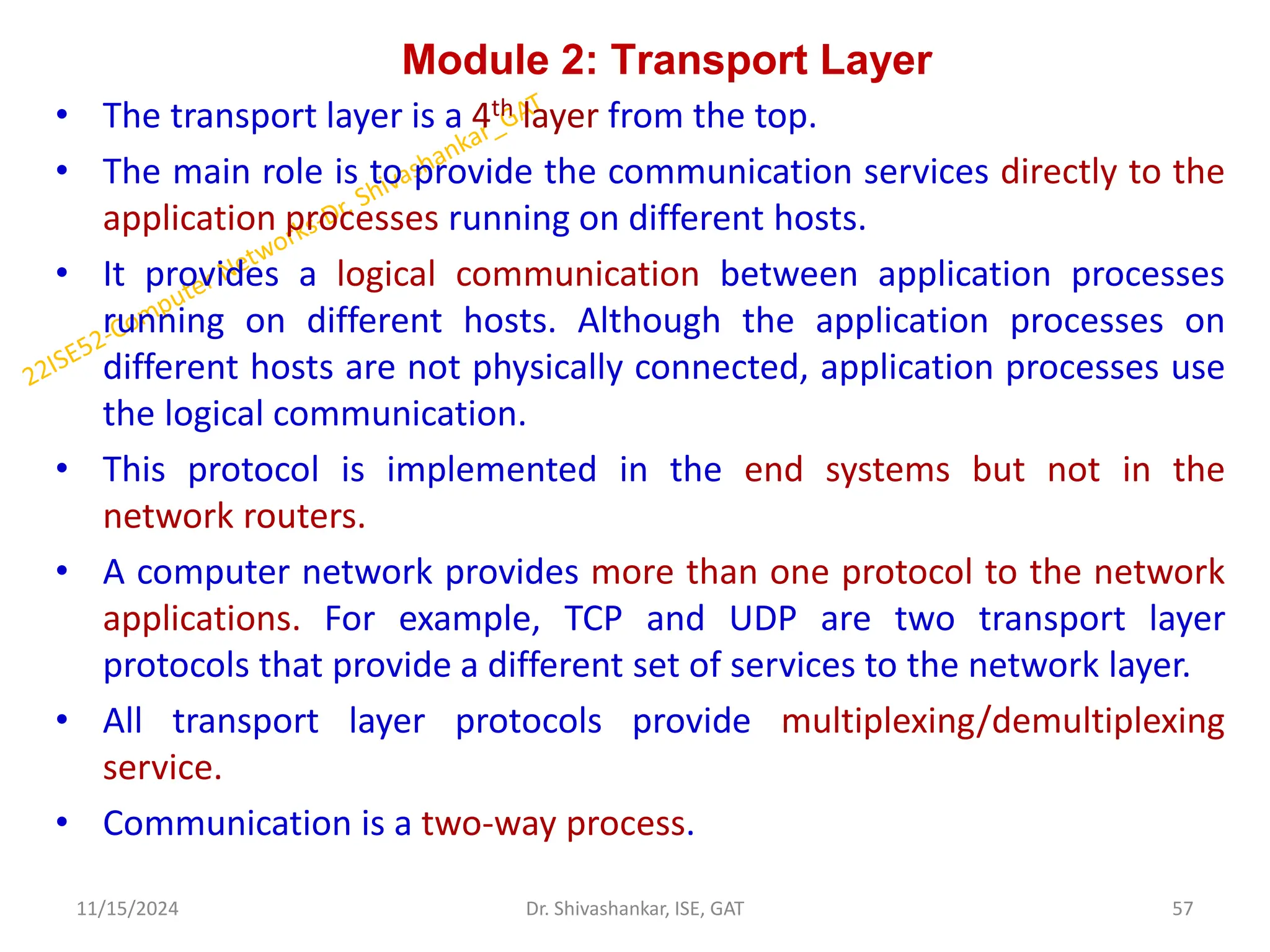
Module 2: TransportLayer
• The transport layer is a 4th layer from the top.
• The main role is to provide the communication services directly to the
application processes running on different hosts.
• It provides a logical communication between application processes
running on different hosts. Although the application processes on
different hosts are not physically connected, application processes use
the logical communication.
• This protocol is implemented in the end systems but not in the
network routers.
• A computer network provides more than one protocol to the network
applications. For example, TCP and UDP are two transport layer
protocols that provide a different set of services to the network layer.
• All transport layer protocols provide multiplexing/demultiplexing
service.
• Communication is a two-way process.
11/15/2024 57
Dr. Shivashankar, ISE, GAT
58.
Conti…
The services providedby the transport layer protocols can be
divided into five categories:
End-to-end delivery: The transport layer transmits the entire
message to the destination.
Addressing: The transport layer provides the user address which is
specified as a station or port.
Reliable delivery: The transport layer provides reliability services by
retransmitting the lost and damaged packets including Error control,
sequential control, Loss control and Duplication control
Flow control: Flow control is used to prevent the sender from
overwhelming the receiver.
Multiplexing: The transport layer uses the multiplexing to improve
transmission efficiency.
11/15/2024 58
Dr. Shivashankar, ISE, GAT
59.
Relationship Between Transportand Network Layers
• The transport and network layers work together to enable communication in a
computer network.
• If the network-layer protocol cannot provide delay or bandwidth guarantees
for transport layer segments sent between hosts, then the transport-layer
protocol cannot provide delay or bandwidth guarantees for application
messages sent between processes.
Network layer:
• Responsible for routing data packets to the correct computer.
• The network layer relies on the transport layer to provide a secure and error-
free transmission.
Transport layer:
• Responsible for ensuring that data is reliably delivered between end systems.
• It takes data from the session layer, breaks it into smaller units if necessary,
and passes it to the network layer.
• The transport layer also checks the received packets for errors and sorts
them.
11/15/2024 59
Dr. Shivashankar, ISE, GAT
60.
Conti..
11/15/2024 60
Dr. Shivashankar,ISE, GAT
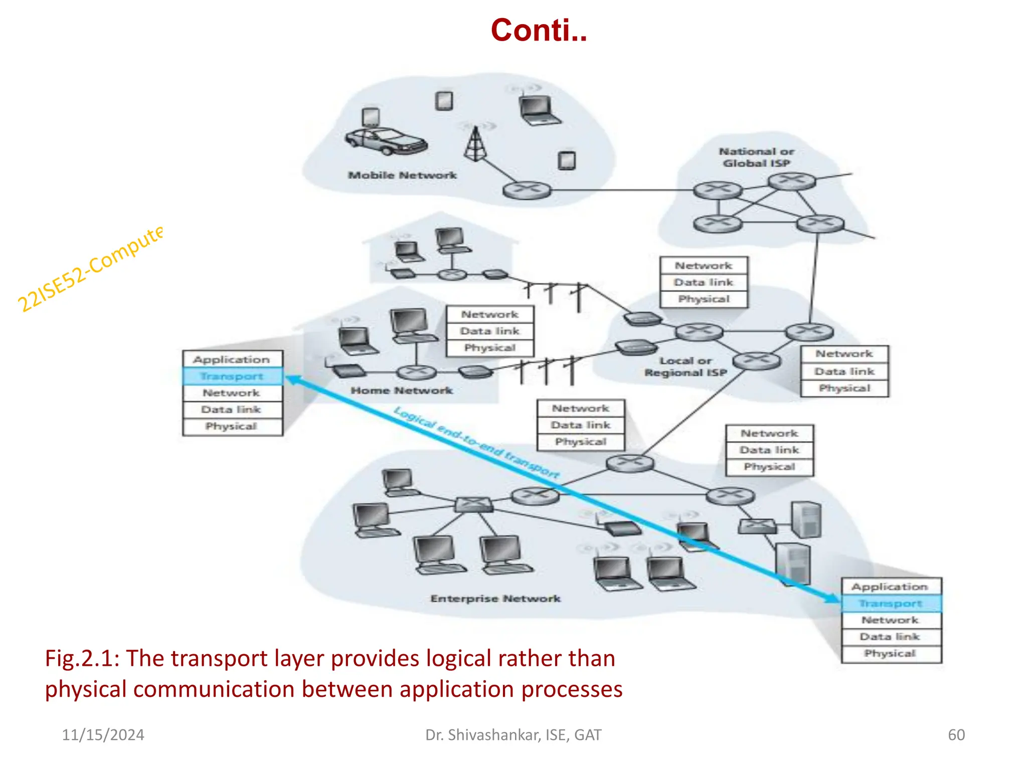
Fig.2.1: The transport layer provides logical rather than
physical communication between application processes
61.
Overview of theTransport Layer in the Internet
Internet, more generally called as a TCP/IP network.
Makes two distinct transport-layer protocols available to the application layer:
TCP and UDP.
Transmission Control Protocol (TCP): provides a reliable, connection-oriented
service to the invoking application, it provides congestion control also.
User Datagram Protocol (UDP): provides an unreliable, connectionless service to
the invoking application.
When designing a network application, the application developer must specify
one of these two transport protocols.
In an Internet context, transport layer packet is called as segment.
Transport Layer in the Internet is responsible for:
Establishing and terminating IP communication sessions
Ensuring data packets arrive accurately and reliably
Controlling the reliability of a given link
Listening for incoming connections
Using standardized port numbers for well-known applications
11/15/2024 61
Dr. Shivashankar, ISE, GAT
62.
Connectionless Transport Protocol
TheUDP protocol allows the computer applications to send the messages in the
form of datagrams from one machine to another machine over the IP network.
The UDP works by encapsulating the data into the packet and providing its own
header information to the packet.
UDP enables the process to process communication, whereas the TCP provides
host to host communication.
UDP also provides a different port number to distinguish different user requests
and also provides the checksum capability to verify whether the complete data
has arrived or not.
The UDP header contains four fields:
Source port number: It is 16-bit information.
Destination port number: It is 16-bit information which is used to identify
application-level service on the destination machine.
Length: It is 16-bit field that specifies the entire length of the UDP packet that
includes the header also.
Checksum: It is a 16-bits field
11/15/2024 62
Dr. Shivashankar, ISE, GAT
63.
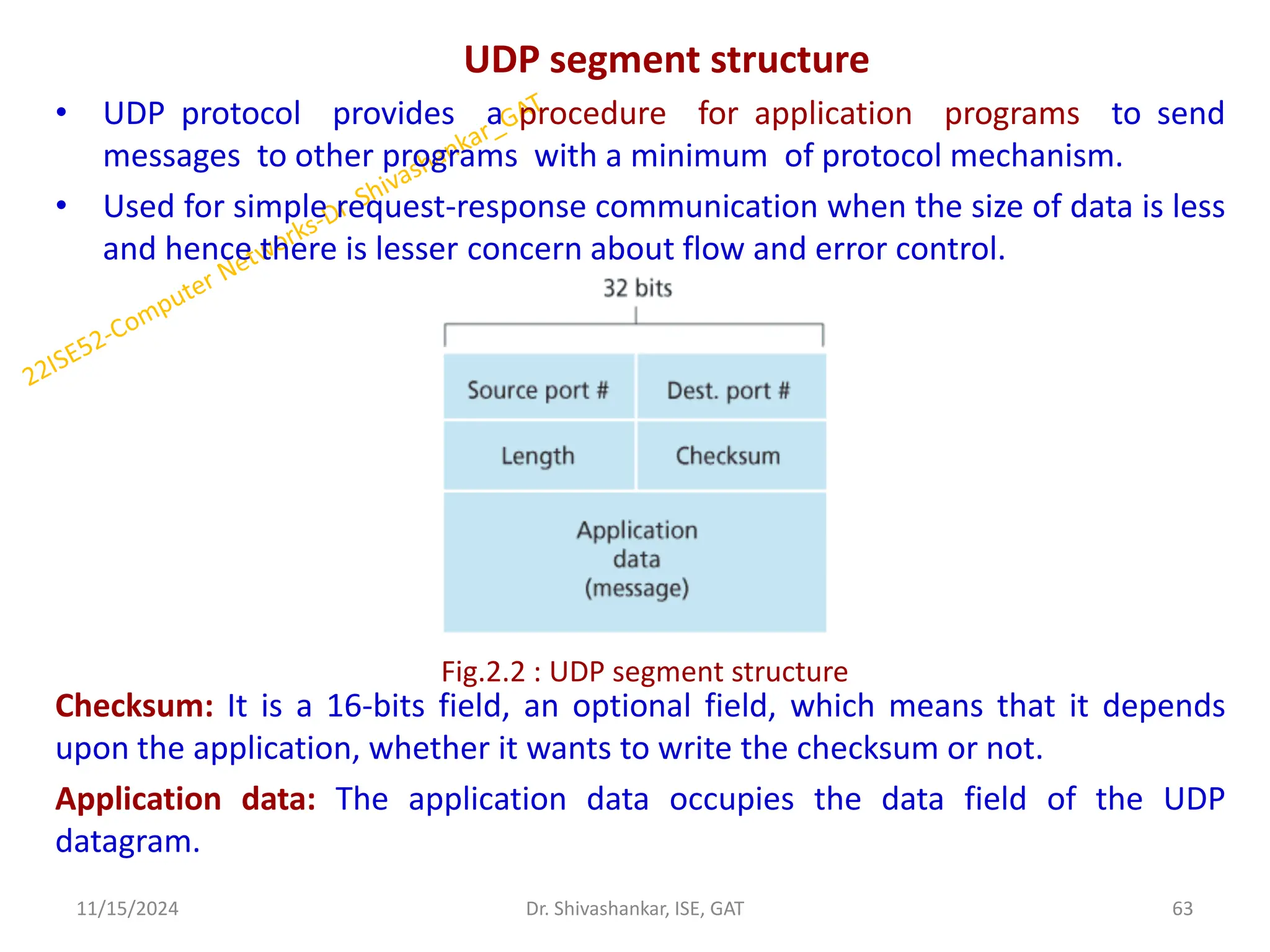
UDP segment structure
•UDP protocol provides a procedure for application programs to send
messages to other programs with a minimum of protocol mechanism.
• Used for simple request-response communication when the size of data is less
and hence there is lesser concern about flow and error control.
Checksum: It is a 16-bits field, an optional field, which means that it depends
upon the application, whether it wants to write the checksum or not.
Application data: The application data occupies the data field of the UDP
datagram.
11/15/2024 63
Dr. Shivashankar, ISE, GAT
Fig.2.2 : UDP segment structure
64.
UDP Checksum
UDP provideschecksums for data integrity, and port numbers for addressing
different functions at the source and destination of the datagram.
The UDP checksum provides for error detection.
That is, the checksum is used to determine whether bits within the UDP
segment have been altered (for example, by noise in the links or while stored in a
router) as it moved from source to destination.
UDP at the sender side performs the 1’s complement of the sum of all the 16-bit
words in the segment, with any overflow encountered during the sum being.
Checksum Calculation:
Sender side:
1. It treats segment contents as sequence of 16-bit integers.
2. All segments are added. Let's call it sum.
3. Checksum: 1's complement of sum.(In 1's complement all 0s are converted
into 1s and all 1s are converted into 0s).
4. Sender puts this checksum value in UDP checksum field.
11/15/2024 64
Dr. Shivashankar, ISE, GAT
65.
Conti..
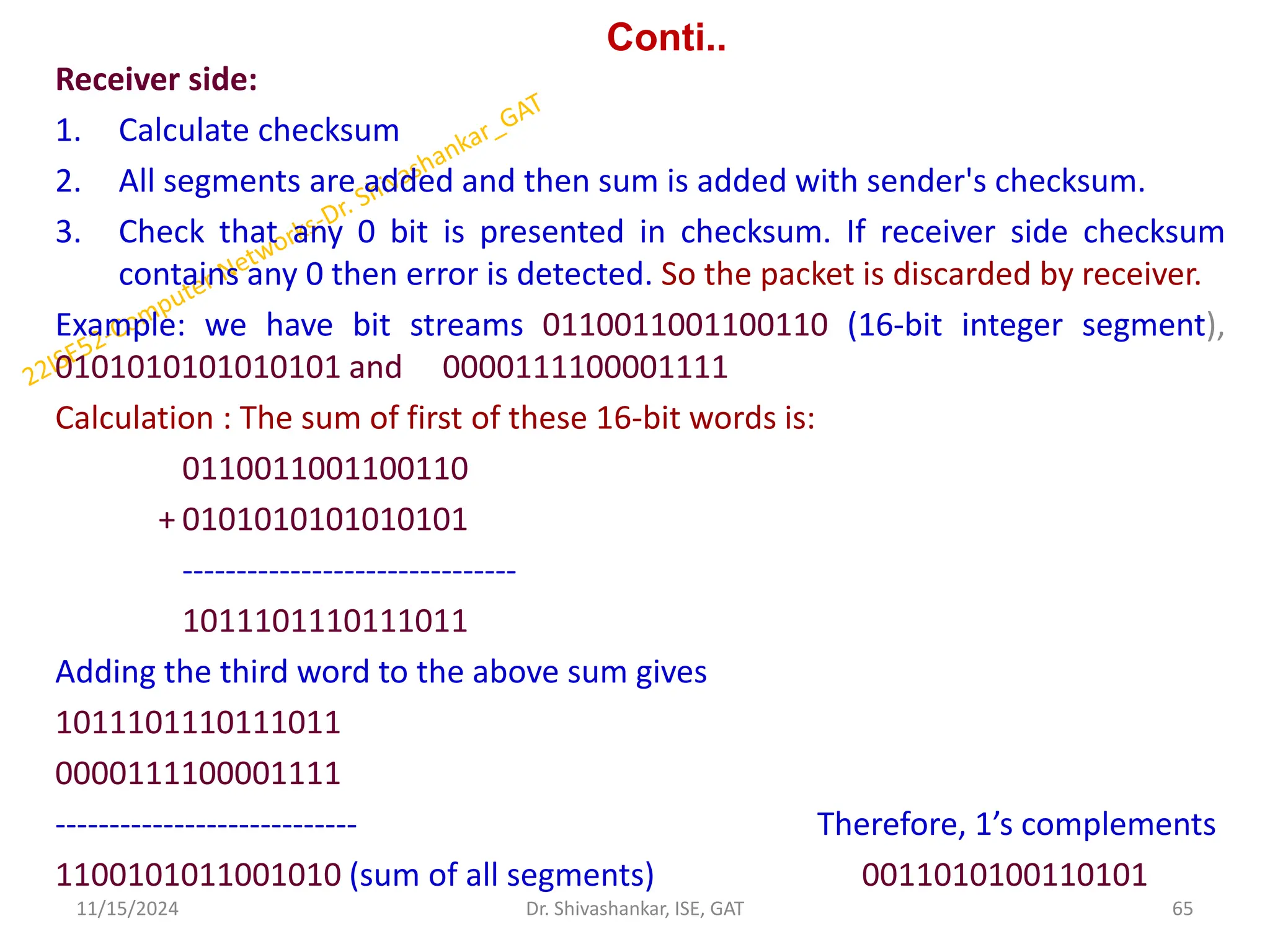
Receiver side:
1. Calculatechecksum
2. All segments are added and then sum is added with sender's checksum.
3. Check that any 0 bit is presented in checksum. If receiver side checksum
contains any 0 then error is detected. So the packet is discarded by receiver.
Example: we have bit streams 0110011001100110 (16-bit integer segment),
0101010101010101 and 0000111100001111
Calculation : The sum of first of these 16-bit words is:
0110011001100110
+ 0101010101010101
-------------------------------
1011101110111011
Adding the third word to the above sum gives
1011101110111011
0000111100001111
---------------------------- Therefore, 1’s complements
1100101011001010 (sum of all segments) 0011010100110101
11/15/2024 65
Dr. Shivashankar, ISE, GAT
66.
Conti..
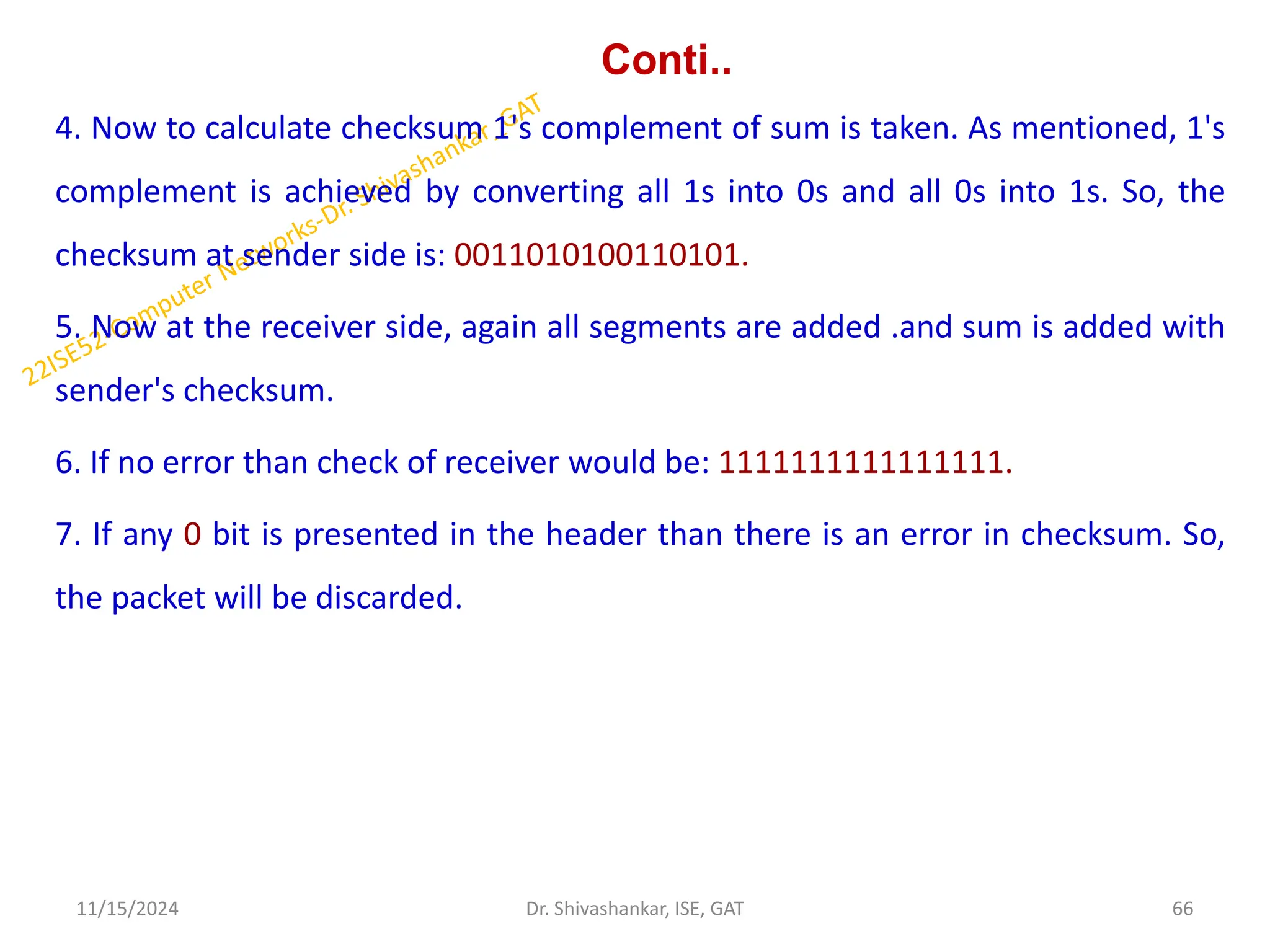
4. Now tocalculate checksum 1's complement of sum is taken. As mentioned, 1's
complement is achieved by converting all 1s into 0s and all 0s into 1s. So, the
checksum at sender side is: 0011010100110101.
5. Now at the receiver side, again all segments are added .and sum is added with
sender's checksum.
6. If no error than check of receiver would be: 1111111111111111.
7. If any 0 bit is presented in the header than there is an error in checksum. So,
the packet will be discarded.
11/15/2024 66
Dr. Shivashankar, ISE, GAT
67.
Conti..
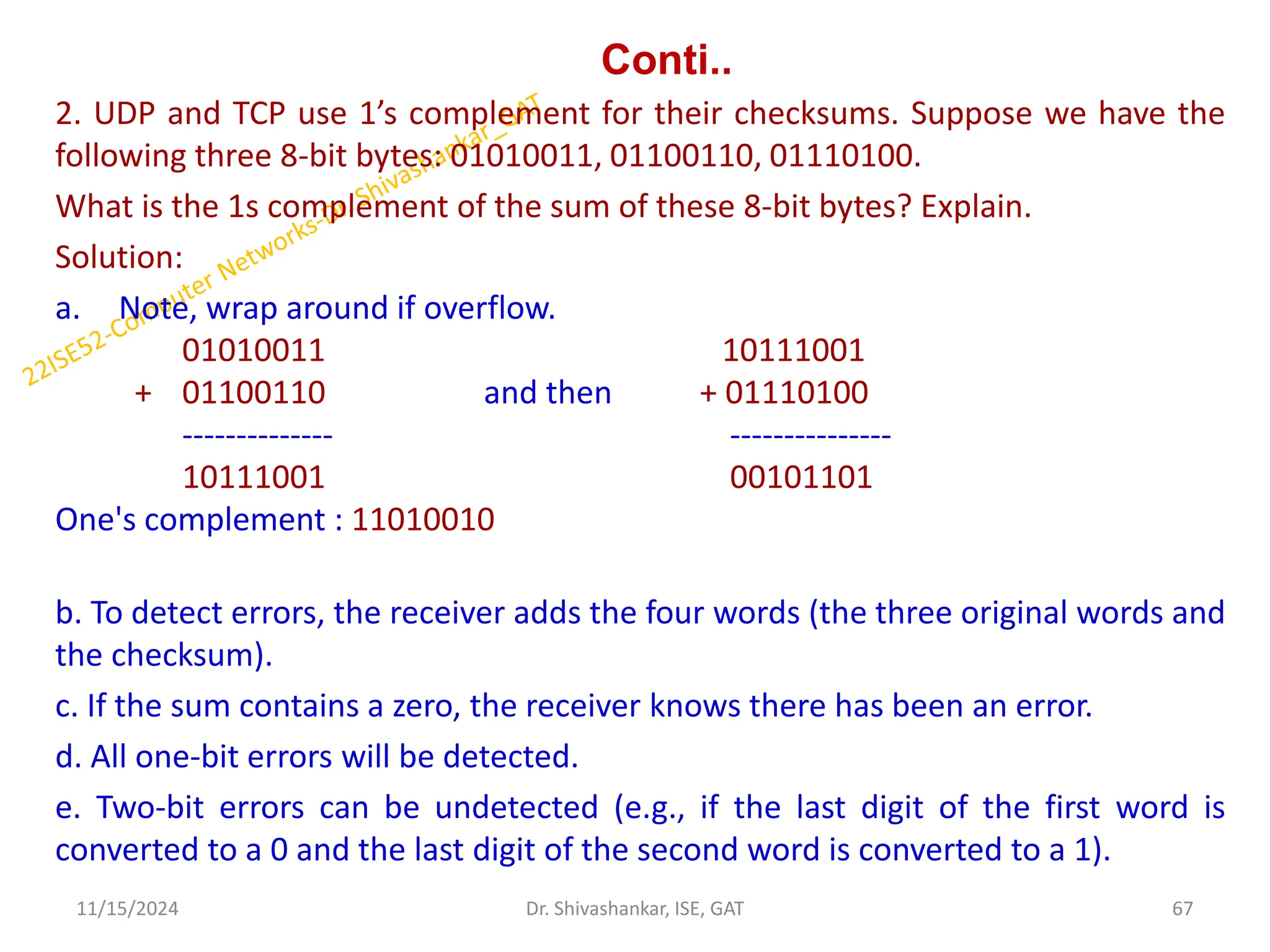
2. UDP andTCP use 1’s complement for their checksums. Suppose we have the
following three 8-bit bytes: 01010011, 01100110, 01110100.
What is the 1s complement of the sum of these 8-bit bytes? Explain.
Solution:
a. Note, wrap around if overflow.
01010011 10111001
+ 01100110 and then + 01110100
-------------- ---------------
10111001 00101101
One's complement : 11010010
b. To detect errors, the receiver adds the four words (the three original words and
the checksum).
c. If the sum contains a zero, the receiver knows there has been an error.
d. All one-bit errors will be detected.
e. Two-bit errors can be undetected (e.g., if the last digit of the first word is
converted to a 0 and the last digit of the second word is converted to a 1).
11/15/2024 67
Dr. Shivashankar, ISE, GAT
![Dynamic Host Configuration Protocol
• Host addresses can also be configured manually, but more often this task is
now done using the Dynamic Host Configuration Protocol (DHCP) [RFC 2131].
• DHCP allows a host to obtain (be allocated) an IP address automatically.
• Because of DHCP’s ability to automate the network-related aspects of
connecting a host into a network, it is often referred to as a plug-and-play
protocol.
11/15/2024 19
Dr. Shivashankar, ISE, GAT
Fig.1.9: DHCP Client Server
Interaction](https://image.slidesharecdn.com/22ise52cnmodule1-241115043322-dd801f22/75/22ISE52_COMPUTER-NETWORKS-_Module-1-pdf-19-2048.jpg)
![CONTI…
Let dx(y) be the cost of the least-cost path from node x to node y. The least costs
are related by Bellman-Ford equation,
dx(y) = minv{c(x,v) + dv(y)}
Where the 𝒎𝒊𝒏𝒗 is the equation taken for all x neighbors.
After traveling from x to v, if we consider the least-cost path from v to y, the path
cost will be c(x,v)+dv(y).
The least cost from x to y is the minimum of c(x,v)+dv(y) taken over all neighbors.
With the Distance Vector Routing algorithm, the node x contains the following
routing information:
For each neighbor v, the cost c(x,v) is the path cost from x to directly attached
neighbor, v.
The distance vector x, i.e., Dx = [ Dx(y) : y in N ], containing its cost to all
destinations, y, in N.
The distance vector of each of its neighbors, i.e., Dv = [ Dv(y) : y in N ] for each
neighbor v of x.
11/15/2024 38
Dr. Shivashankar, ISE, GAT](https://image.slidesharecdn.com/22ise52cnmodule1-241115043322-dd801f22/75/22ISE52_COMPUTER-NETWORKS-_Module-1-pdf-38-2048.jpg)
![Algorithm
At each node x,
Initialization
Step 1: for all destinations y in N:
Step 2: Dx(y) = c(x,y) // If y is not a neighbor then c(x,y) = ∞
Step 3: for each neighbor w
Step 4: Dw(y) = ? for all destination y in N.
Step 5: for each neighbor w
Step 6: send distance vector Dx = [ Dx(y) : y in N ] to w
Step 7: loop
Step 9: wait(until I receive any distance vector from some neighbor w)
Step 10: for each y in N:
Step 11: Dx(y) = minv{c(x,v)+Dv(y)}
Step 12: If Dx(y) is changed for any destination y
Step 13: Send distance vector Dx = [ Dx(y) : y in N ] to all neighbors
Step 14: forever
11/15/2024 39
Dr. Shivashankar, ISE, GAT](https://image.slidesharecdn.com/22ise52cnmodule1-241115043322-dd801f22/75/22ISE52_COMPUTER-NETWORKS-_Module-1-pdf-39-2048.jpg)


![Dynamic Host Configuration Protocol
• Host addresses can also be configured manually, but more often this task is
now done using the Dynamic Host Configuration Protocol (DHCP) [RFC 2131].
• DHCP allows a host to obtain (be allocated) an IP address automatically.
• Because of DHCP’s ability to automate the network-related aspects of
connecting a host into a network, it is often referred to as a plug-and-play
protocol.
11/15/2024 19
Dr. Shivashankar, ISE, GAT
Fig.1.9: DHCP Client Server
Interaction](https://crownmelresort.com/image.slidesharecdn.com/22ise52cnmodule1-241115043322-dd801f22/75/22ISE52_COMPUTER-NETWORKS-_Module-1-pdf-19-2048.jpg)


![CONTI…
Let dx(y) be the cost of the least-cost path from node x to node y. The least costs
are related by Bellman-Ford equation,
dx(y) = minv{c(x,v) + dv(y)}
Where the 𝒎𝒊𝒏𝒗 is the equation taken for all x neighbors.
After traveling from x to v, if we consider the least-cost path from v to y, the path
cost will be c(x,v)+dv(y).
The least cost from x to y is the minimum of c(x,v)+dv(y) taken over all neighbors.
With the Distance Vector Routing algorithm, the node x contains the following
routing information:
For each neighbor v, the cost c(x,v) is the path cost from x to directly attached
neighbor, v.
The distance vector x, i.e., Dx = [ Dx(y) : y in N ], containing its cost to all
destinations, y, in N.
The distance vector of each of its neighbors, i.e., Dv = [ Dv(y) : y in N ] for each
neighbor v of x.
11/15/2024 38
Dr. Shivashankar, ISE, GAT](https://crownmelresort.com/image.slidesharecdn.com/22ise52cnmodule1-241115043322-dd801f22/75/22ISE52_COMPUTER-NETWORKS-_Module-1-pdf-38-2048.jpg)
![Algorithm
At each node x,
Initialization
Step 1: for all destinations y in N:
Step 2: Dx(y) = c(x,y) // If y is not a neighbor then c(x,y) = ∞
Step 3: for each neighbor w
Step 4: Dw(y) = ? for all destination y in N.
Step 5: for each neighbor w
Step 6: send distance vector Dx = [ Dx(y) : y in N ] to w
Step 7: loop
Step 9: wait(until I receive any distance vector from some neighbor w)
Step 10: for each y in N:
Step 11: Dx(y) = minv{c(x,v)+Dv(y)}
Step 12: If Dx(y) is changed for any destination y
Step 13: Send distance vector Dx = [ Dx(y) : y in N ] to all neighbors
Step 14: forever
11/15/2024 39
Dr. Shivashankar, ISE, GAT](https://crownmelresort.com/image.slidesharecdn.com/22ise52cnmodule1-241115043322-dd801f22/75/22ISE52_COMPUTER-NETWORKS-_Module-1-pdf-39-2048.jpg)