The document discusses a computer networks course taught by Dr. Shivashankar at RRIT. It outlines the course objectives, modules, and key topics covered, including network layer protocols and functions, IP addressing, routing, and fragmentation. Key concepts covered are packet switching, forwarding, and network layer protocols like IP, ICMP, ARP, and DHCP.
Course Outcomes
After Completionof the course, student will be able to
Understand the concepts of networking thoroughly.
Describe the various network architectures
Identify the protocols and services of different layers
Distinguish the basic network configurations and
standards associated with each network models.
Analyze a simple network and measurements of its
parameters.
Text Book:
Data Communications and Networking , Forouzan, 5th
Edition, McGraw Hill, 2016 ISBN: 1-25-906475-3
2/11/2023 2
Dr. Shivashankar, E&CE, RRIT
3.
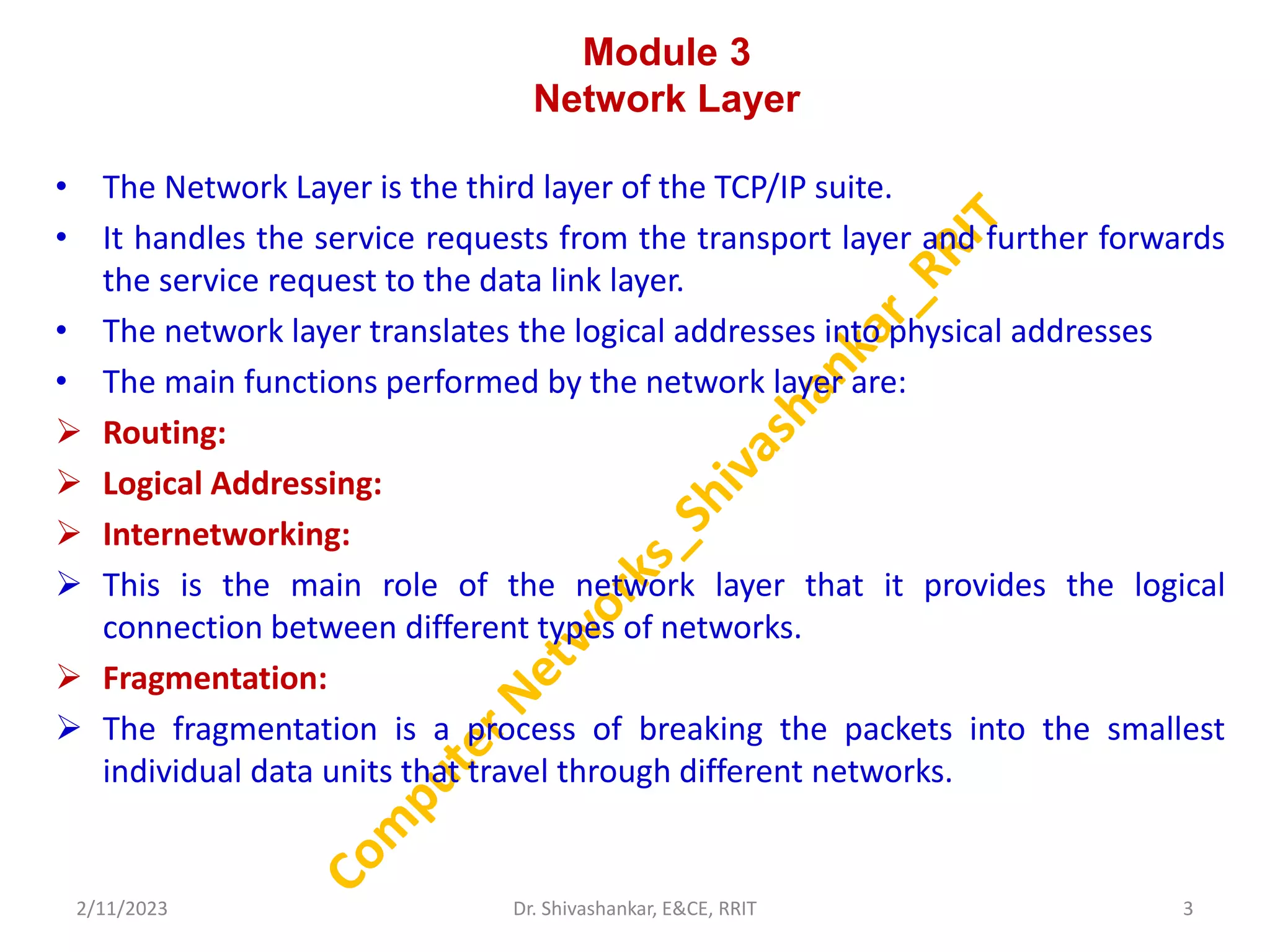
Module 3
Network Layer
•The Network Layer is the third layer of the TCP/IP suite.
• It handles the service requests from the transport layer and further forwards
the service request to the data link layer.
• The network layer translates the logical addresses into physical addresses
• The main functions performed by the network layer are:
Routing:
Logical Addressing:
Internetworking:
This is the main role of the network layer that it provides the logical
connection between different types of networks.
Fragmentation:
The fragmentation is a process of breaking the packets into the smallest
individual data units that travel through different networks.
2/11/2023 3
Dr. Shivashankar, E&CE, RRIT
4.
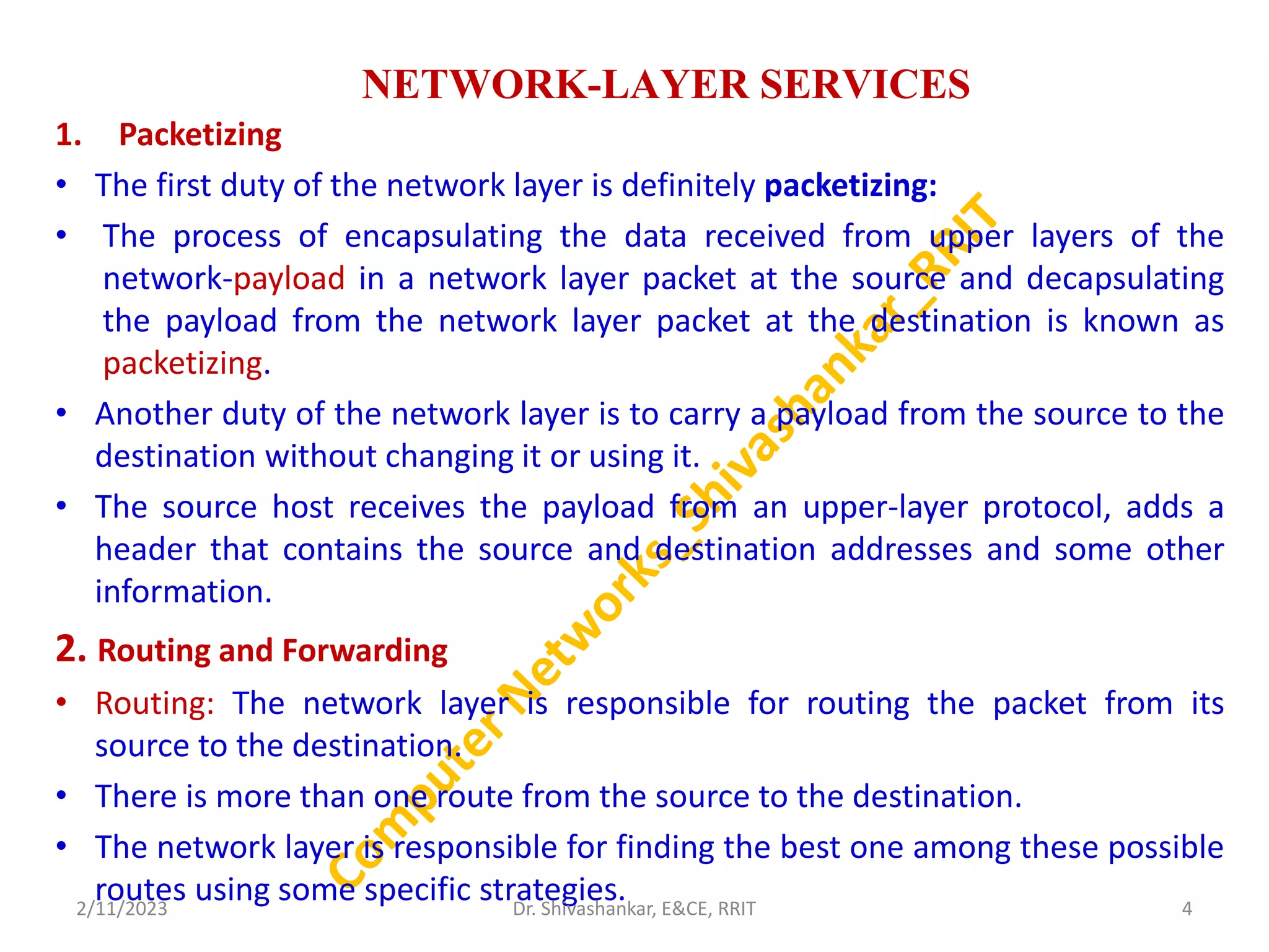
NETWORK-LAYER SERVICES
1. Packetizing
•The first duty of the network layer is definitely packetizing:
• The process of encapsulating the data received from upper layers of the
network-payload in a network layer packet at the source and decapsulating
the payload from the network layer packet at the destination is known as
packetizing.
• Another duty of the network layer is to carry a payload from the source to the
destination without changing it or using it.
• The source host receives the payload from an upper-layer protocol, adds a
header that contains the source and destination addresses and some other
information.
2. Routing and Forwarding
• Routing: The network layer is responsible for routing the packet from its
source to the destination.
• There is more than one route from the source to the destination.
• The network layer is responsible for finding the best one among these possible
routes using some specific strategies.
2/11/2023 4
Dr. Shivashankar, E&CE, RRIT
5.
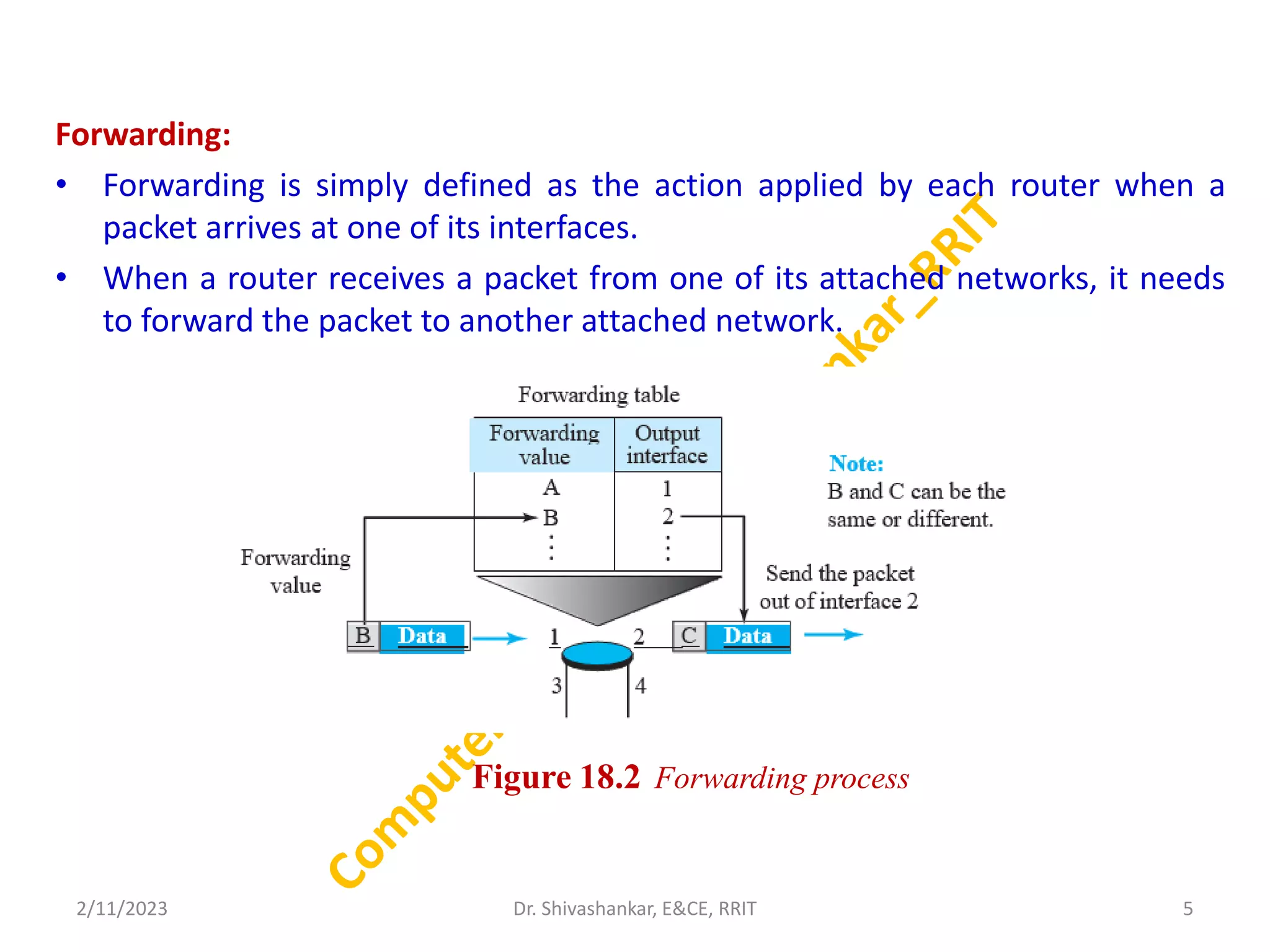
Forwarding:
• Forwarding issimply defined as the action applied by each router when a
packet arrives at one of its interfaces.
• When a router receives a packet from one of its attached networks, it needs
to forward the packet to another attached network.
2/11/2023 5
Dr. Shivashankar, E&CE, RRIT
Figure 18.2 Forwarding process
6.
Other Services
Error Control
Flowcontrol
Congestion control : Congestion may occur if the number of datagrams sent by
source computers is beyond the capacity of the network or routers. In this
situation, some routers may drop some of the datagrams.
Quality of Service: As the Internet has allowed new applications such as
multimedia communication (in particular real-time communication of audio and
video), the quality of service (QoS) of the communication has become more and
more important.
Security : The network layer was designed with no security provision.
Today, however, security is a big concern.
To provide security for a connectionless network layer, we need to have another
virtual level that changes the connectionless service to a connection-oriented
service.
This virtual layer, called IPSec.
2/11/2023 6
Dr. Shivashankar, E&CE, RRIT
7.
PACKET SWITCHING
• Arouter, in fact, is a switch that creates a connection between an input port
and an output port, just as an electrical switch connects the input to the
output to let electricity flow.
• Data communication switching techniques are divided into two broad
categories,
circuit switching and
packet switching.
• Circuit switching is mostly used at the physical layer; the electrical switch
mentioned earlier is a kind of circuit switch.
• Packet switching is a method of transferring the data to a network in form of
packets.
• Today, a packet-switched network can use two different approaches to route
the packets: the datagram approach and the virtual circuit approach.
2/11/2023 7
Dr. Shivashankar, E&CE, RRIT
8.
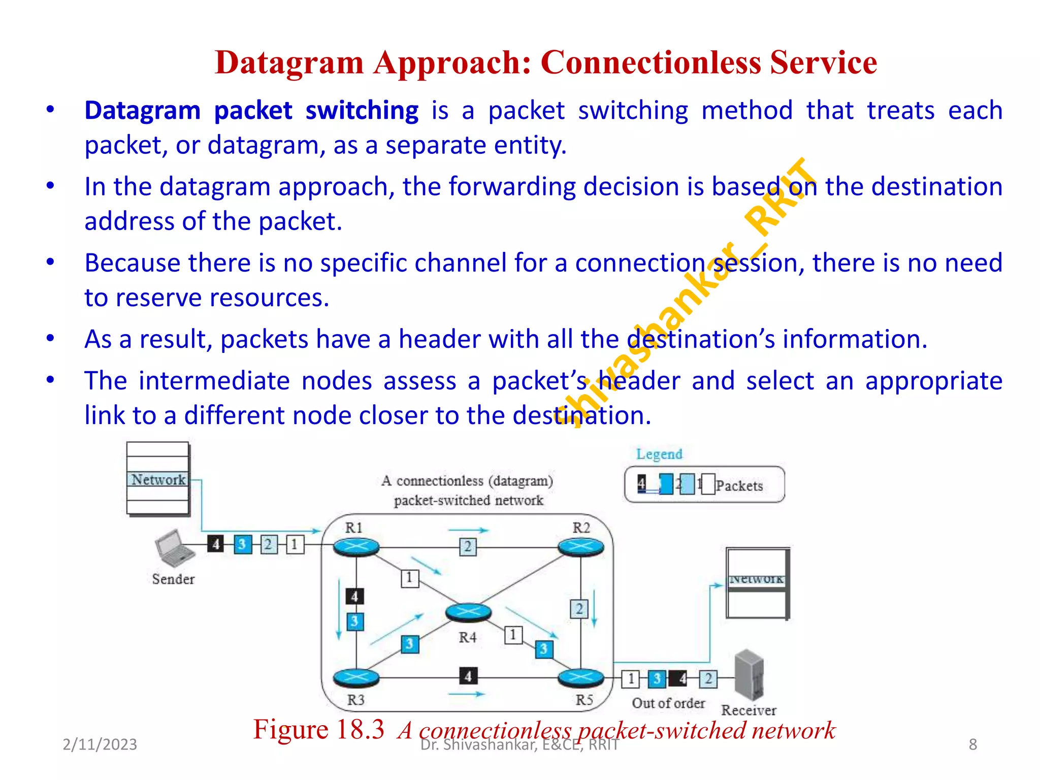
Datagram Approach: ConnectionlessService
• Datagram packet switching is a packet switching method that treats each
packet, or datagram, as a separate entity.
• In the datagram approach, the forwarding decision is based on the destination
address of the packet.
• Because there is no specific channel for a connection session, there is no need
to reserve resources.
• As a result, packets have a header with all the destination’s information.
• The intermediate nodes assess a packet’s header and select an appropriate
link to a different node closer to the destination.
2/11/2023 8
Dr. Shivashankar, E&CE, RRIT
Figure 18.3 A connectionless packet-switched network
9.
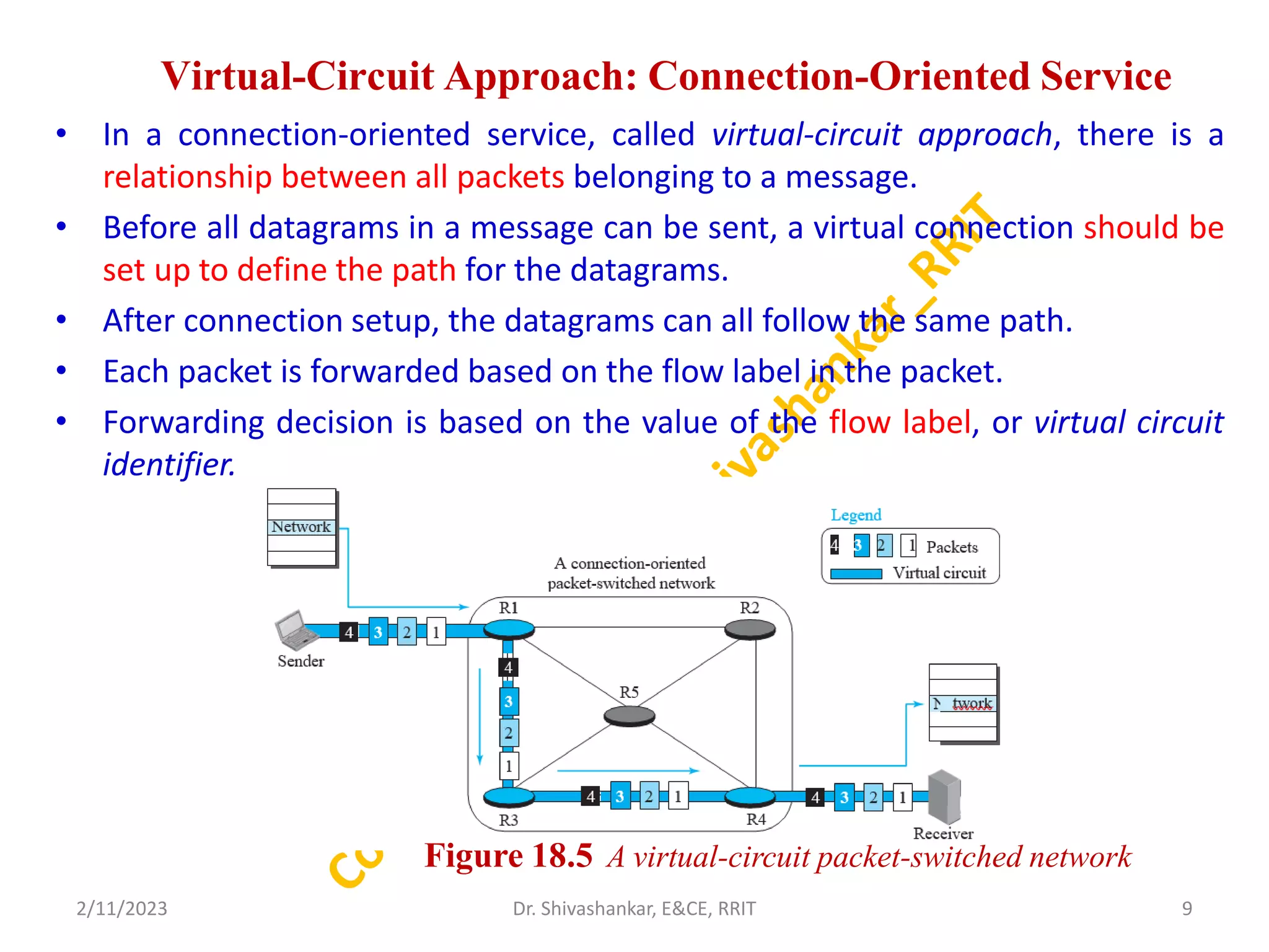
Virtual-Circuit Approach: Connection-OrientedService
• In a connection-oriented service, called virtual-circuit approach, there is a
relationship between all packets belonging to a message.
• Before all datagrams in a message can be sent, a virtual connection should be
set up to define the path for the datagrams.
• After connection setup, the datagrams can all follow the same path.
• Each packet is forwarded based on the flow label in the packet.
• Forwarding decision is based on the value of the flow label, or virtual circuit
identifier.
2/11/2023 9
Dr. Shivashankar, E&CE, RRIT
Figure 18.5 A virtual-circuit packet-switched network
10.
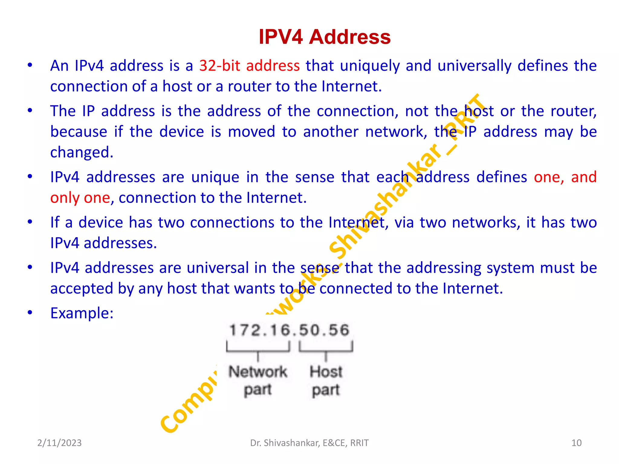
IPV4 Address
• AnIPv4 address is a 32-bit address that uniquely and universally defines the
connection of a host or a router to the Internet.
• The IP address is the address of the connection, not the host or the router,
because if the device is moved to another network, the IP address may be
changed.
• IPv4 addresses are unique in the sense that each address defines one, and
only one, connection to the Internet.
• If a device has two connections to the Internet, via two networks, it has two
IPv4 addresses.
• IPv4 addresses are universal in the sense that the addressing system must be
accepted by any host that wants to be connected to the Internet.
• Example:
2/11/2023 10
Dr. Shivashankar, E&CE, RRIT
11.
Address Space
• Anaddress space is the total number of addresses used by the protocol.
• If a protocol uses b bits to define an address, the address space is 2b because each bit
can have two different values (0 or 1).
• IPv4 uses 32-bit addresses, which means that the address space is 232 or 4,294,967,296
(more than four billion).
• If there were no restrictions, more than 4 billion devices could be connected to the
Internet.
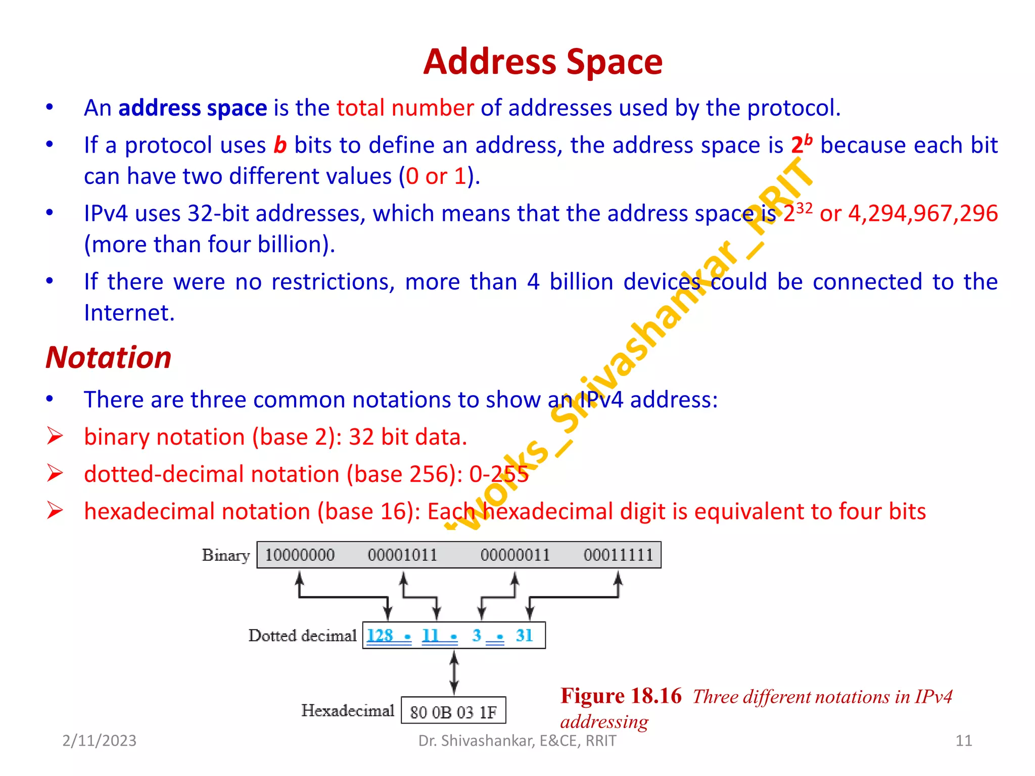
Notation
• There are three common notations to show an IPv4 address:
binary notation (base 2): 32 bit data.
dotted-decimal notation (base 256): 0-255
hexadecimal notation (base 16): Each hexadecimal digit is equivalent to four bits
2/11/2023 11
Dr. Shivashankar, E&CE, RRIT
Figure 18.16 Three different notations in IPv4
addressing
12.
Classful Addressing
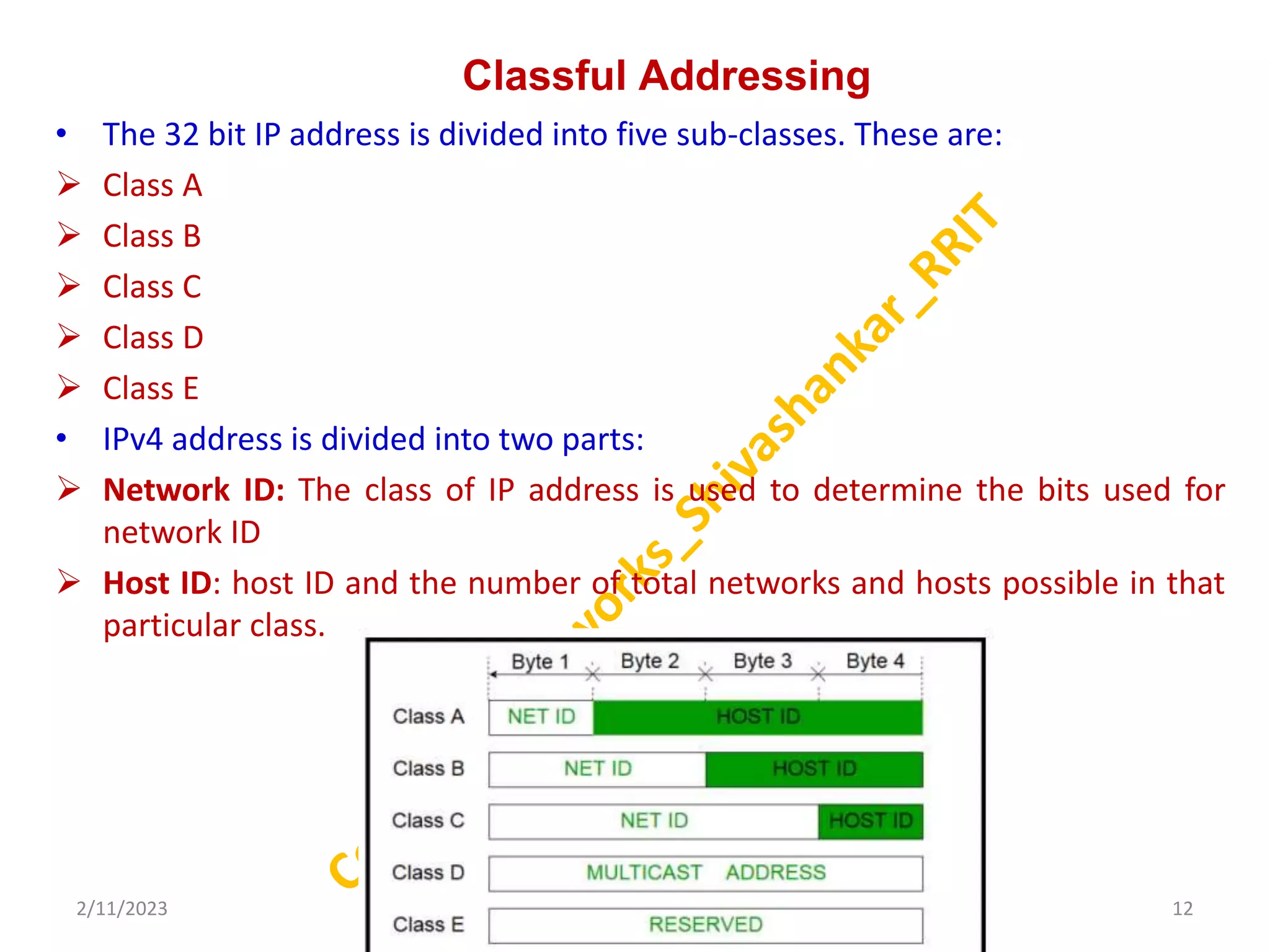
• The32 bit IP address is divided into five sub-classes. These are:
Class A
Class B
Class C
Class D
Class E
• IPv4 address is divided into two parts:
Network ID: The class of IP address is used to determine the bits used for
network ID
Host ID: host ID and the number of total networks and hosts possible in that
particular class.
2/11/2023 12
Dr. Shivashankar, E&CE, RRIT
13.
conti..
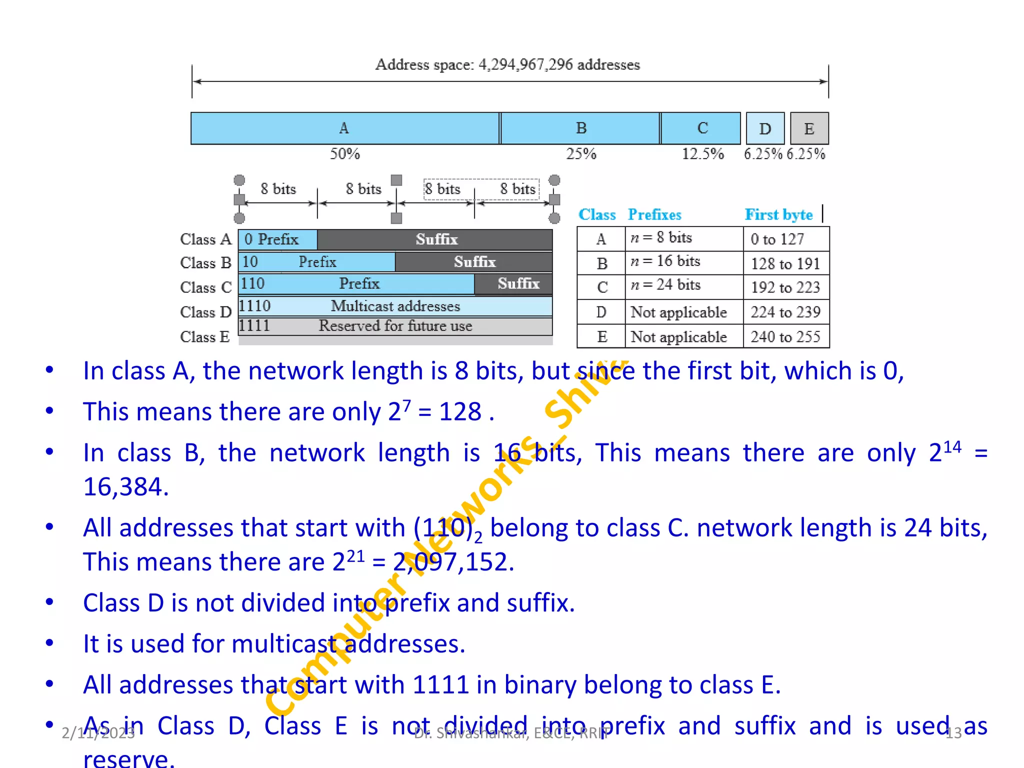
• In classA, the network length is 8 bits, but since the first bit, which is 0,
• This means there are only 27 = 128 .
• In class B, the network length is 16 bits, This means there are only 214 =
16,384.
• All addresses that start with (110)2 belong to class C. network length is 24 bits,
This means there are 221 = 2,097,152.
• Class D is not divided into prefix and suffix.
• It is used for multicast addresses.
• All addresses that start with 1111 in binary belong to class E.
• As in Class D, Class E is not divided into prefix and suffix and is used as
2/11/2023 13
Dr. Shivashankar, E&CE, RRIT
14.
Classless Adressing
• In1996, the Internet authorities announced a new architecture called
classless addressing.
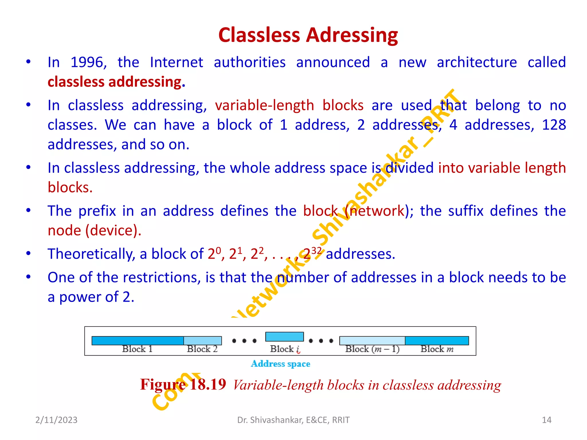
• In classless addressing, variable-length blocks are used that belong to no
classes. We can have a block of 1 address, 2 addresses, 4 addresses, 128
addresses, and so on.
• In classless addressing, the whole address space is divided into variable length
blocks.
• The prefix in an address defines the block (network); the suffix defines the
node (device).
• Theoretically, a block of 20, 21, 22, . . . , 232 addresses.
• One of the restrictions, is that the number of addresses in a block needs to be
a power of 2.
2/11/2023 14
Dr. Shivashankar, E&CE, RRIT
Figure 18.19 Variable-length blocks in classless addressing
15.
Dynamic Host ConfigurationProtocol (DHCP)
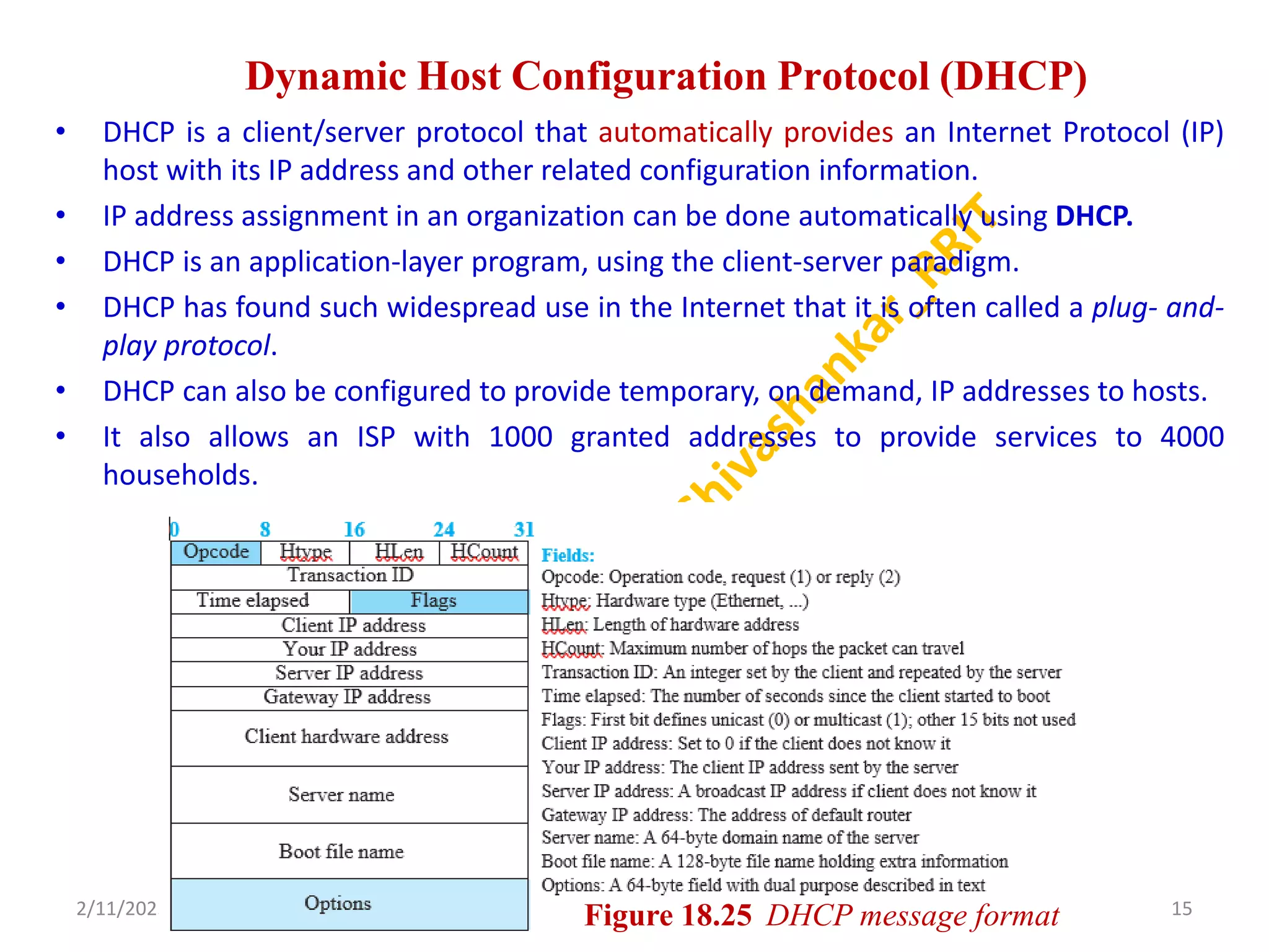
• DHCP is a client/server protocol that automatically provides an Internet Protocol (IP)
host with its IP address and other related configuration information.
• IP address assignment in an organization can be done automatically using DHCP.
• DHCP is an application-layer program, using the client-server paradigm.
• DHCP has found such widespread use in the Internet that it is often called a plug- and-
play protocol.
• DHCP can also be configured to provide temporary, on demand, IP addresses to hosts.
• It also allows an ISP with 1000 granted addresses to provide services to 4000
households.
2/11/2023 15
Dr. Shivashankar, E&CE, RRIT
Figure 18.25 DHCP message format
16.
Network Address Resolution(NAT)
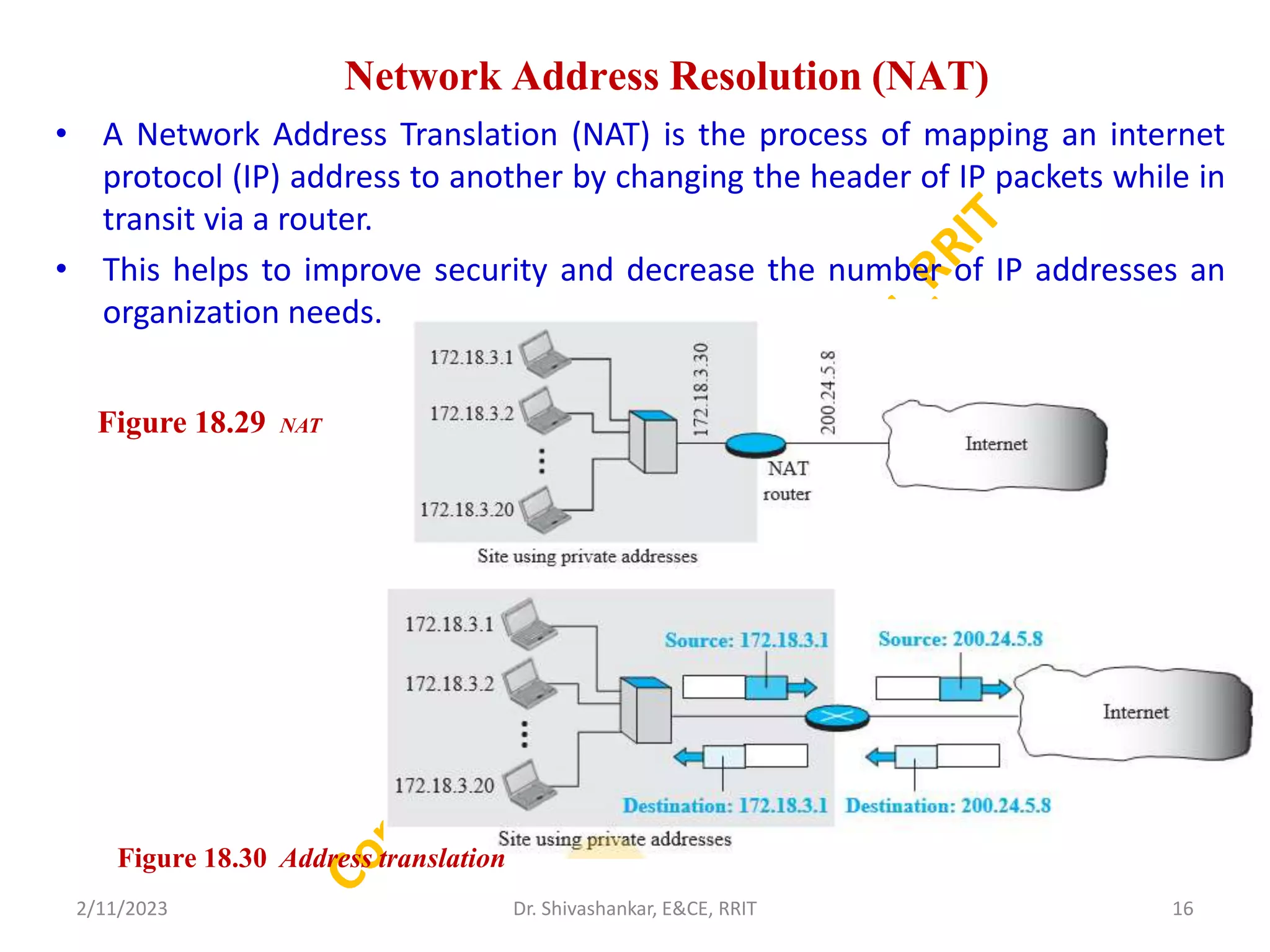
• A Network Address Translation (NAT) is the process of mapping an internet
protocol (IP) address to another by changing the header of IP packets while in
transit via a router.
• This helps to improve security and decrease the number of IP addresses an
organization needs.
2/11/2023 16
Dr. Shivashankar, E&CE, RRIT
Figure 18.29 NAT
Figure 18.30 Address translation
17.
FORWARDING OF IPPACKETS
• Since the Internet today is made of a combination of links
(networks), forwarding means to deliver the packet to the next
hop (which can be the final destination or the intermediate
connecting device).
• Although the IP protocol was originally designed as a
connectionless protocol, today the tendency is to change it to a
connection-oriented protocol.
• When IP is used as a connectionless protocol, forwarding is
based on the destination address of the IP datagram;
• when the IP is used as a connection-oriented protocol,
forwarding is based on the label attached to an IP datagram.
2/11/2023 17
Dr. Shivashankar, E&CE, RRIT
18.
Forwarding Based onDestination Address
• Forwarding requires a host or a router to have a forwarding table. When a
host has a packet to send or when a router has received a packet to be
forwarded, it looks at this table to find the next hop to deliver the packet to.
• In classless addressing, the whole address space is one entity; there are no
classes.
• Unfortunately, the destination address in the packet gives no clue about the
net- work address.
• To solve the problem, we need to include the mask (/n) in the table. In other
words, a classless forwarding table needs to include four pieces of
information: the mask,
the network address,
the interface number,
and the IP address of the next router
2/11/2023 18
Dr. Shivashankar, E&CE, RRIT
19.
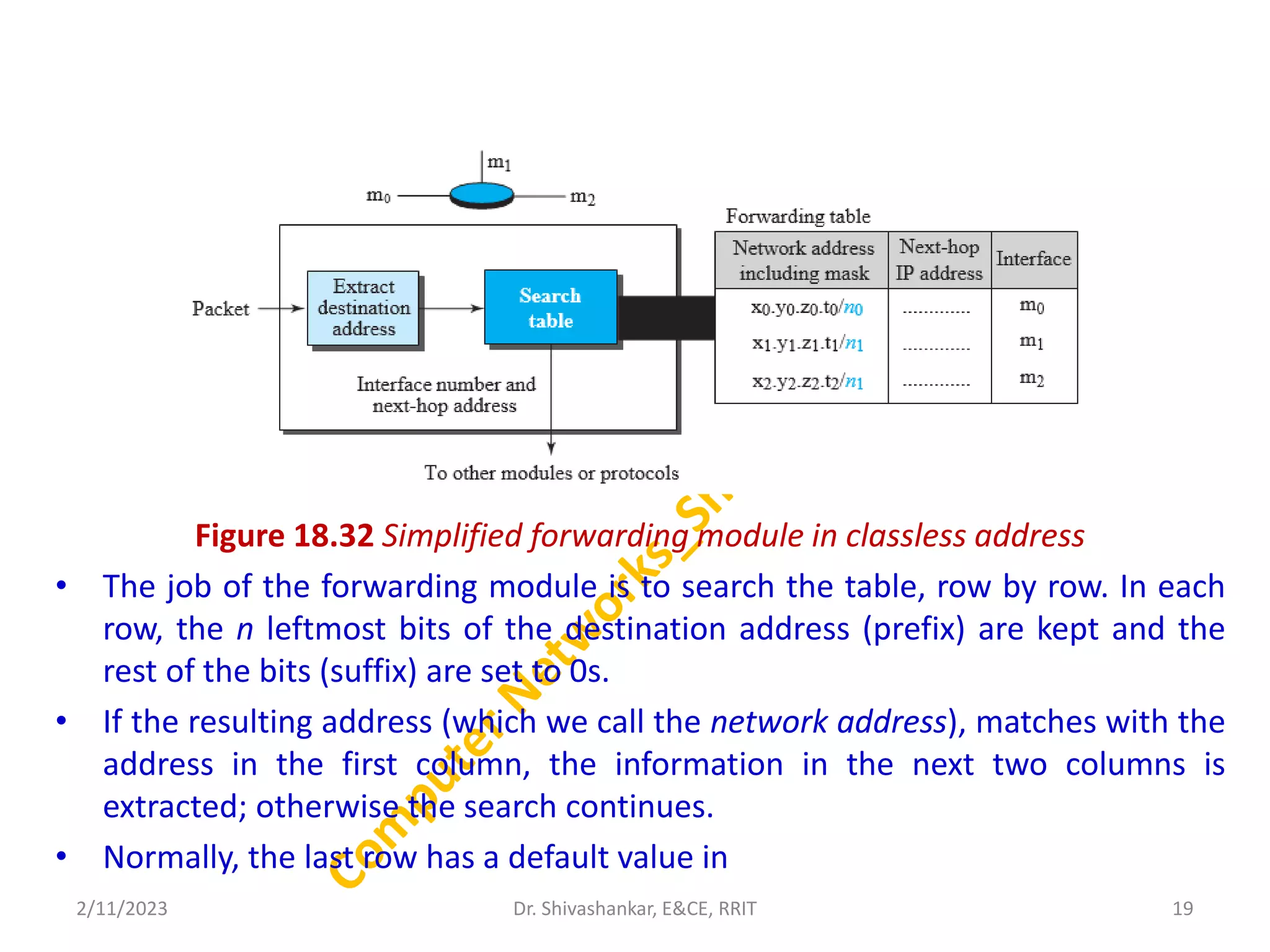
Figure 18.32 Simplifiedforwarding module in classless address
• The job of the forwarding module is to search the table, row by row. In each
row, the n leftmost bits of the destination address (prefix) are kept and the
rest of the bits (suffix) are set to 0s.
• If the resulting address (which we call the network address), matches with the
address in the first column, the information in the next two columns is
extracted; otherwise the search continues.
• Normally, the last row has a default value in
2/11/2023 19
Dr. Shivashankar, E&CE, RRIT
20.
Forwarding Based onLabel
• In the 1980s, an effort started to somehow change IP to behave
like a connection- oriented protocol in which the routing is
replaced by switching.
• In a connectionless network (datagram approach), a router
forwards a packet based on the destination address in the
header of the packet.
• In a connection-oriented network (virtual-circuit approach), a
switch forwards a packet based on the label attached to the
packet.
• Routing is normally based on searching the contents of a table;
switching can be done by accessing a table using an index.
• In other words, routing involves searching; switching involves
accessing.
2/11/2023 20
Dr. Shivashankar, E&CE, RRIT
21.
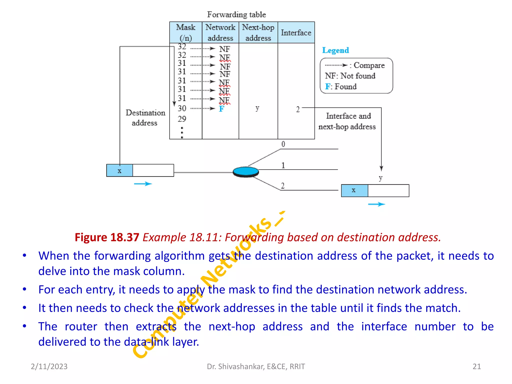
Figure 18.37 Example18.11: Forwarding based on destination address.
• When the forwarding algorithm gets the destination address of the packet, it needs to
delve into the mask column.
• For each entry, it needs to apply the mask to find the destination network address.
• It then needs to check the network addresses in the table until it finds the match.
• The router then extracts the next-hop address and the interface number to be
delivered to the data-link layer.
2/11/2023 21
Dr. Shivashankar, E&CE, RRIT
22.
Network-Layer Protocols
INTERNET PROTOCOL(IP)
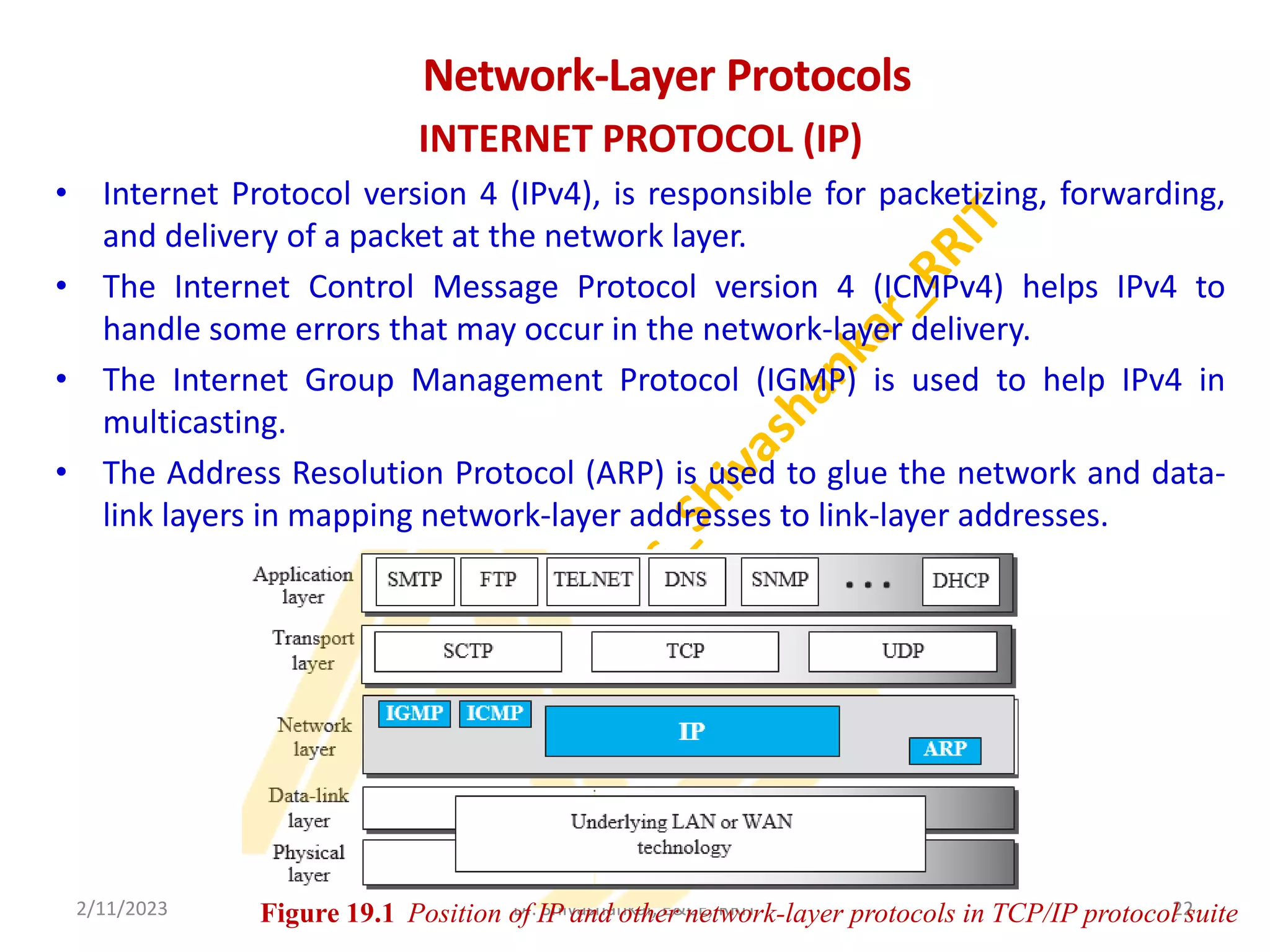
• Internet Protocol version 4 (IPv4), is responsible for packetizing, forwarding,
and delivery of a packet at the network layer.
• The Internet Control Message Protocol version 4 (ICMPv4) helps IPv4 to
handle some errors that may occur in the network-layer delivery.
• The Internet Group Management Protocol (IGMP) is used to help IPv4 in
multicasting.
• The Address Resolution Protocol (ARP) is used to glue the network and data-
link layers in mapping network-layer addresses to link-layer addresses.
2/11/2023 22
Dr. Shivashankar, E&CE, RRIT
Figure 19.1 Position of IP and other network-layer protocols in TCP/IP protocol suite
23.
Datagram Format
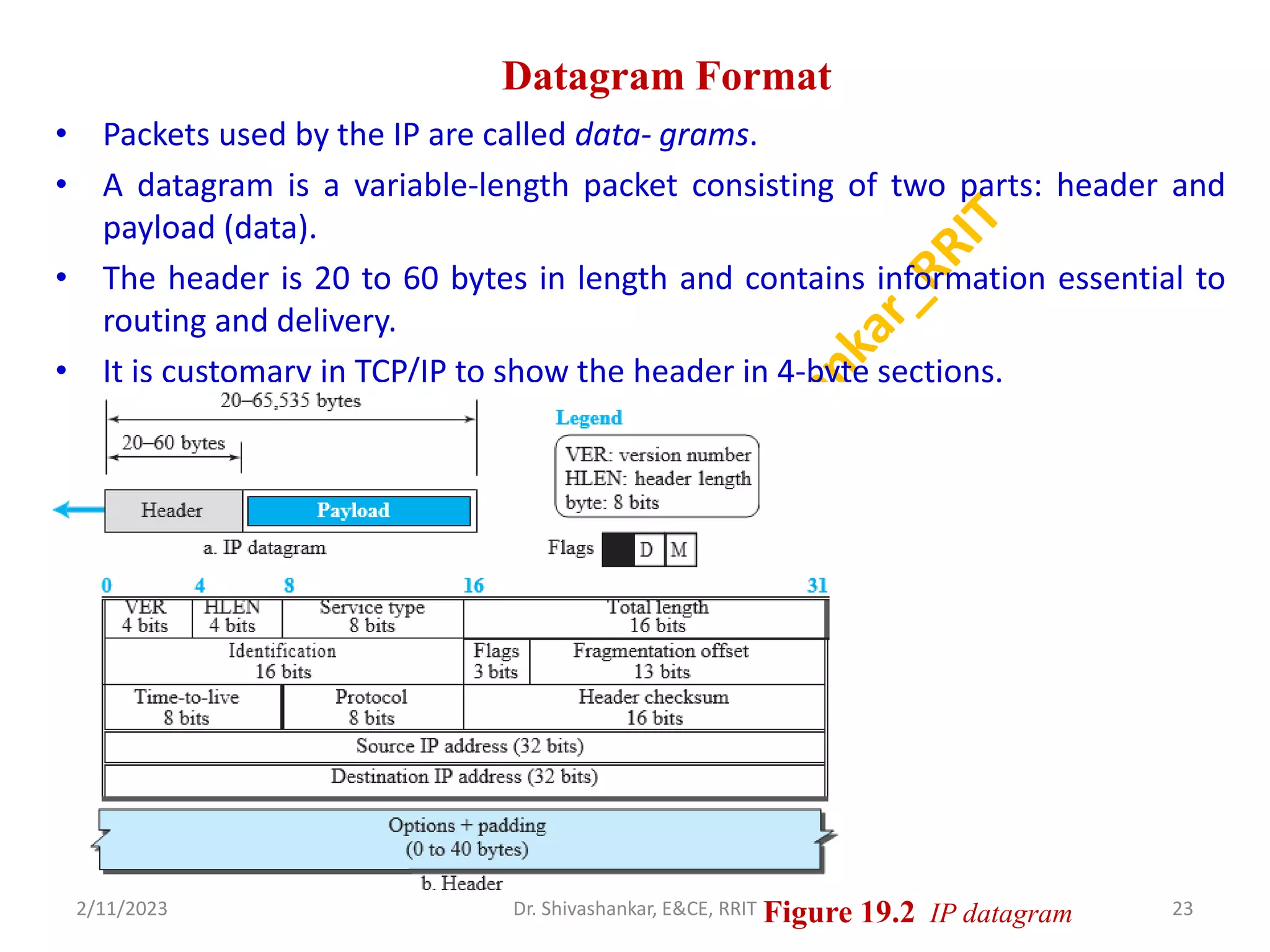
• Packetsused by the IP are called data- grams.
• A datagram is a variable-length packet consisting of two parts: header and
payload (data).
• The header is 20 to 60 bytes in length and contains information essential to
routing and delivery.
• It is customary in TCP/IP to show the header in 4-byte sections.
2/11/2023 23
Dr. Shivashankar, E&CE, RRIT Figure 19.2 IP datagram
24.
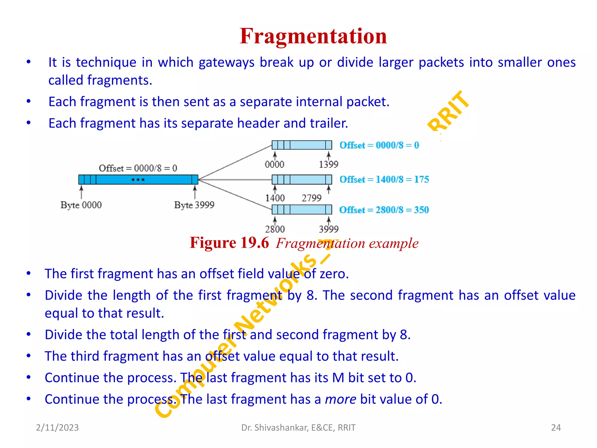
Fragmentation
• It istechnique in which gateways break up or divide larger packets into smaller ones
called fragments.
• Each fragment is then sent as a separate internal packet.
• Each fragment has its separate header and trailer.
• The first fragment has an offset field value of zero.
• Divide the length of the first fragment by 8. The second fragment has an offset value
equal to that result.
• Divide the total length of the first and second fragment by 8.
• The third fragment has an offset value equal to that result.
• Continue the process. The last fragment has its M bit set to 0.
• Continue the process. The last fragment has a more bit value of 0.
2/11/2023 24
Dr. Shivashankar, E&CE, RRIT
Figure 19.6 Fragmentation example
25.
Options
• Options canbe used for network testing and debugging.
• Option processing is required of the IPv4 software.
• This means that all implementations must be able to handle options if they
are present in the header.
• Options are divided into two broad categories:
1. Single-Byte Options:
• No Operation: A no-operation option is a 1-byte option used as a filler
between options.
• End of Option: An end-of-option option is a 1-byte option used for padding at
the end of the option field.
2. Multliple-Byte Options:
• Record Route: A record route option is used to record the Internet routers that
handle the datagram.
• Strict Source Route: A strict source route option is used by the source to
predetermine a route for the data- gram as it travels through the Internet.
2/11/2023 25
Dr. Shivashankar, E&CE, RRIT
26.
Security of IPv4Datagrams
• No security was provided for the IPv4 protocol.
The Internet is not secure anymore.
• There are three security issues, applicable to
the IP protocol:
packet sniffing,
packet modification,
and IP spoofing.
2/11/2023 26
Dr. Shivashankar, E&CE, RRIT
27.
Packet Sniffing
• Anintruder may intercept an IP packet and make a copy of it.
• Packet sniffing is a passive attack, in which the attacker does not
change the contents of the packet.
• This type of attack is very difficult to detect because the sender
and the receiver may never know that the packet has been
copied. Although packet sniffing cannot be stopped, encryption
of the packet can make the attacker’s effort useless.
• The attacker may still sniff the packet, but the content is not
detectable.
• Ex: Pass word Sniffing
• TCP Session Hijacking
• DNS Poisoning
• DHCP attacking
• ARP sniffing
2/11/2023 27
Dr. Shivashankar, E&CE, RRIT
28.
Packet Modification
• Thesecond type of attack is to modify the packet.
• The attacker intercepts the packet, changes its contents, and sends the new
packet to the receiver.
• The receiver believes that the packet is coming from the original sender.
• This type of attack can be detected using a data integrity mechanism.
• The receiver, before opening and using the contents of the message, can use
this mechanism to make sure that the packet has not been changed during
the transmission.
• Examples of Modification attacks include:
• Modifying the contents of messages in the network.
• Changing information stored in data files.
• Altering programs so they perform differently.
• Reconfiguring system hardware or network topologies.
2/11/2023 28
Dr. Shivashankar, E&CE, RRIT
29.
IP Spoofing
• Anattacker can masquerade as somebody else and create an IP packet that
carries the source address of another computer.
• An attacker can send an IP packet to a bank pretending that it is coming from
one of the customers.
• This type of attack can be prevented using an origin authentication
mechanism.
• Types of IP spoofing
Distributed Denial of Service (DDoS) attacks: This allows them to slow down
or crash a website or network with large volumes of internet traffic .
Masking botnet devices: A botnet is a network of computers that hacker’s
control from a single source.
Man-in-the-middle attacks: Another malicious IP spoofing method uses
a ‘man-in-the-middle’ attack to interrupt communication between two
computers, alter the packets, and transmit them without the original sender
or receiver knowing.
2/11/2023 29
Dr. Shivashankar, E&CE, RRIT
30.
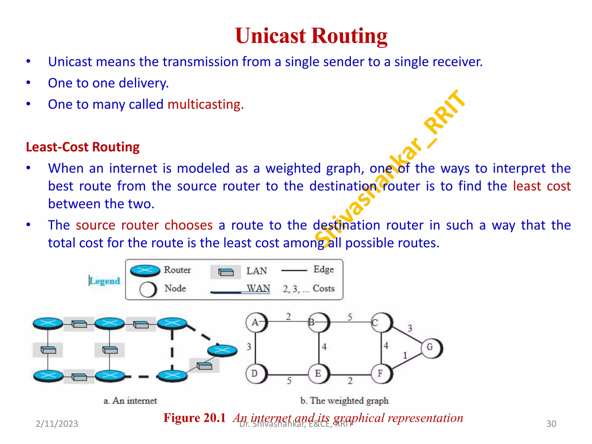
Unicast Routing
• Unicastmeans the transmission from a single sender to a single receiver.
• One to one delivery.
• One to many called multicasting.
Least-Cost Routing
• When an internet is modeled as a weighted graph, one of the ways to interpret the
best route from the source router to the destination router is to find the least cost
between the two.
• The source router chooses a route to the destination router in such a way that the
total cost for the route is the least cost among all possible routes.
2/11/2023 30
Dr. Shivashankar, E&CE, RRIT
Figure 20.1 An internet and its graphical representation
31.
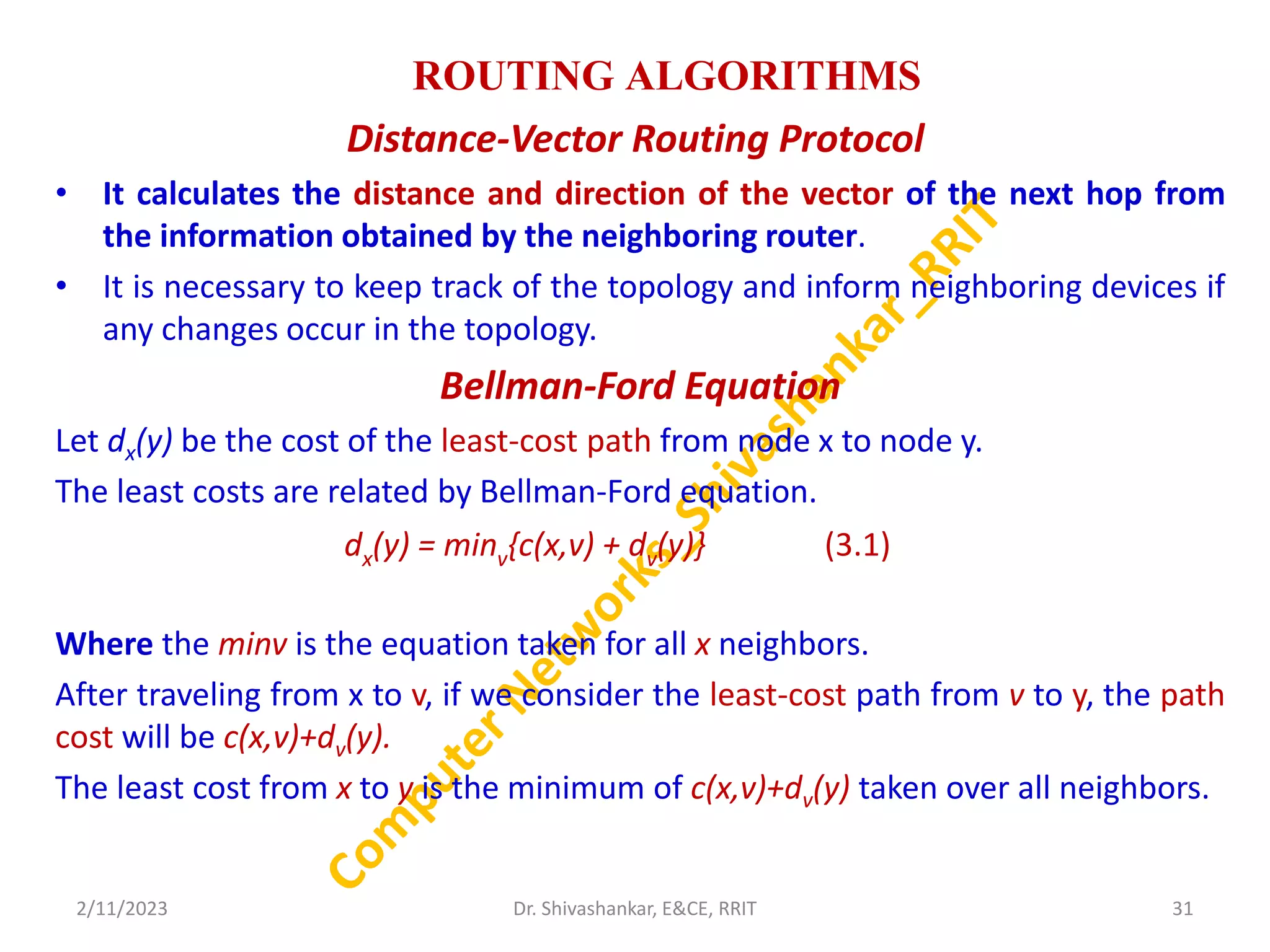
ROUTING ALGORITHMS
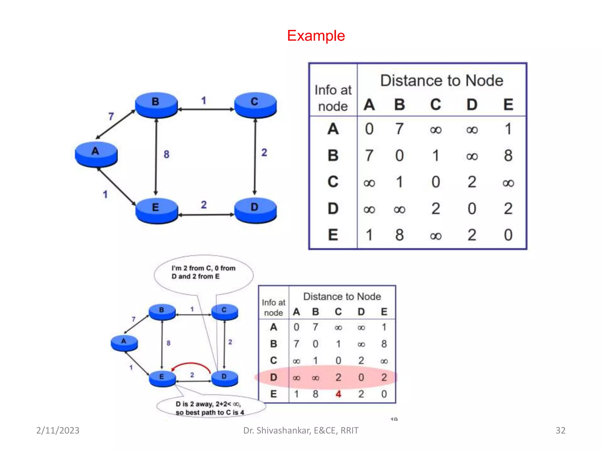
Distance-Vector RoutingProtocol
• It calculates the distance and direction of the vector of the next hop from
the information obtained by the neighboring router.
• It is necessary to keep track of the topology and inform neighboring devices if
any changes occur in the topology.
Bellman-Ford Equation
Let dx(y) be the cost of the least-cost path from node x to node y.
The least costs are related by Bellman-Ford equation.
Where the minv is the equation taken for all x neighbors.
After traveling from x to v, if we consider the least-cost path from v to y, the path
cost will be c(x,v)+dv(y).
The least cost from x to y is the minimum of c(x,v)+dv(y) taken over all neighbors.
2/11/2023 31
Dr. Shivashankar, E&CE, RRIT
dx(y) = minv{c(x,v) + dv(y)} (3.1)
Distance_Vector_Routing ( )
{
D[myself] = 0
for (y = 1 to N)
{
if (y is a neighbor)
D[y] = c[myself ][y]
else
D[y] = ∞
}
send vector {D[1], D[2], ,,, D[N]} to all neighbors
{
wait (for a vector Dw from a neighbor w or any change in the link)
for (y = 1 to N)
{
D[y] = min [D[y], (c[myself ][w] + Dw[y ])] // Bellman-Ford equation
}
if (any change in the vector)
send vector {D[1], D[2],,,, D[N]} to all neighbors
}
}
2/11/2023 33
Dr. Shivashankar, E&CE, RRIT
34.
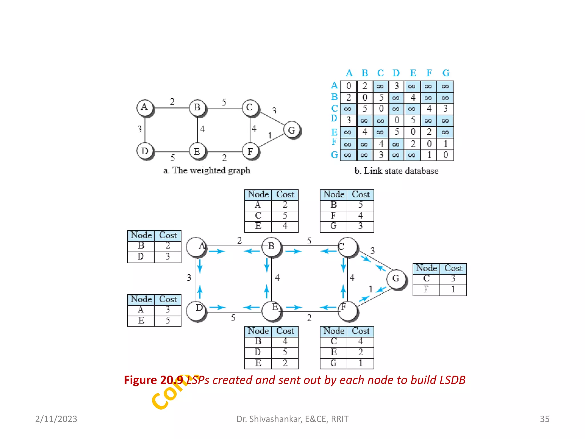
Link-State Routing
• Linkstate routing is a method in which each router shares its
neighbourhood’s knowledge with every other router in the
internetwork.
• In this algorithm, each router in the network understands the network
topology then makes a routing table depend on this topology.
• Each router will share data about its connection to its neighbour, who
will, consecutively, reproduce the data to its neighbours, etc.
• This appears just before all routers have constructed a topology of the
network.
• This method uses the term link-state to define the characteristic of a
link (an edge) that represents a network in the internet.
• In this algorithm the cost associated with an edge defines the state of
the link. Links with lower costs are preferred to links with higher costs;
if the cost of a link is infinity, it means that the link does not exist or
has been broken.
2/11/2023 34
Dr. Shivashankar, E&CE, RRIT
35.
Figure 20.9 LSPscreated and sent out by each node to build LSDB
2/11/2023 35
Dr. Shivashankar, E&CE, RRIT
36.
Dijkstra’s Algorithm
2/11/2023 36
Dr.Shivashankar, E&CE, RRIT
for (y = 1 to N) // n number of nodes
{
if (y is the root)
D[y] = 0 // D[y] is shortest distance from root to node y
else if (y is a neighbor)
D[y] = c[root][y] // c[x][y] is cost between nodes x and y in LSDB
else
D[y] = ∞
}
Repeat
{
find a node w, with D[w] minimum among all nodes not in the Tree
Tree = Tree U{w}
for (every node x, which is a neighbor of w and not in the Tree)
{
D[x] = min{D[x], (D[w] + c[w][x])}
}
} until (all nodes included in the Tree)
}
37.
Module 4
TRANSPORT-LAYER PROTOCOLS
•The transport layer is a 4th layer from the top.
• The main role of the transport layer is to provide the
communication services directly to the application processes
running on different hosts.
• The transport layer provides a logical communication between
application processes running on different hosts.
• Although the application processes on different hosts are not
physically connected, application processes use the logical
communication provided by the transport layer to send the
messages to each other.
• The transport layer protocols are implemented in the end
systems, but not in the network routers.
2/11/2023 37
Dr. Shivashankar, E&CE, RRIT
38.
Transport-Layer Services
Process-to-Process Communication
•The first duty of a transport-layer protocol is to provide process-to-process
communication.
• A process is an application-layer entity (running program) that uses the
services of the transport layer.
Addressing: Port Numbers:
• A process on the local host, called a client, needs services from a process
usually on the remote host, called a server.
• A port number is a way to identify a specific process to which an internet or
other network message is to be forwarded when it arrives at a server.
• All network-connected devices come equipped with standardized ports that
have an assigned number.
• These numbers are reserved for certain protocols and their associated
function. Hypertext Transfer Protocol (HTTP) messages, for example, always
go to port 80.
2/11/2023 38
Dr. Shivashankar, E&CE, RRIT
39.
Flow Control:
• Flowcontrol is used to prevent the sender from overwhelming the receiver.
If the receiver is overloaded with too much data, then the receiver discards
the packets and asking for the retransmission of packets.
• This increases network congestion and thus, reducing the system
performance.
Error Control:
• Error control at the transport layer is responsible for
1. Detecting and discarding corrupted packets.
2. Keeping track of lost and discarded packets and resending them.
3. Recognizing duplicate packets and discarding them.
4. Buffering out-of-order packets until the missing packets arrive.
Congestion Control:
• Congestion in a network may occur if the load on the network—the
number of packets sent to the network is greater than the capacity of the
network.
2/11/2023 39
Dr. Shivashankar, E&CE, RRIT
40.
Connectionless and Connection-OrientedProtocols
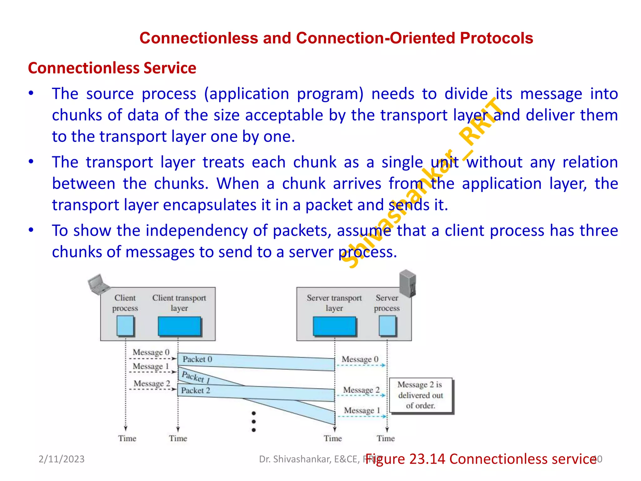
Connectionless Service
• The source process (application program) needs to divide its message into
chunks of data of the size acceptable by the transport layer and deliver them
to the transport layer one by one.
• The transport layer treats each chunk as a single unit without any relation
between the chunks. When a chunk arrives from the application layer, the
transport layer encapsulates it in a packet and sends it.
• To show the independency of packets, assume that a client process has three
chunks of messages to send to a server process.
2/11/2023 40
Dr. Shivashankar, E&CE, RRIT
Figure 23.14 Connectionless service
41.
Connectionless and Connection-OrientedProtocols
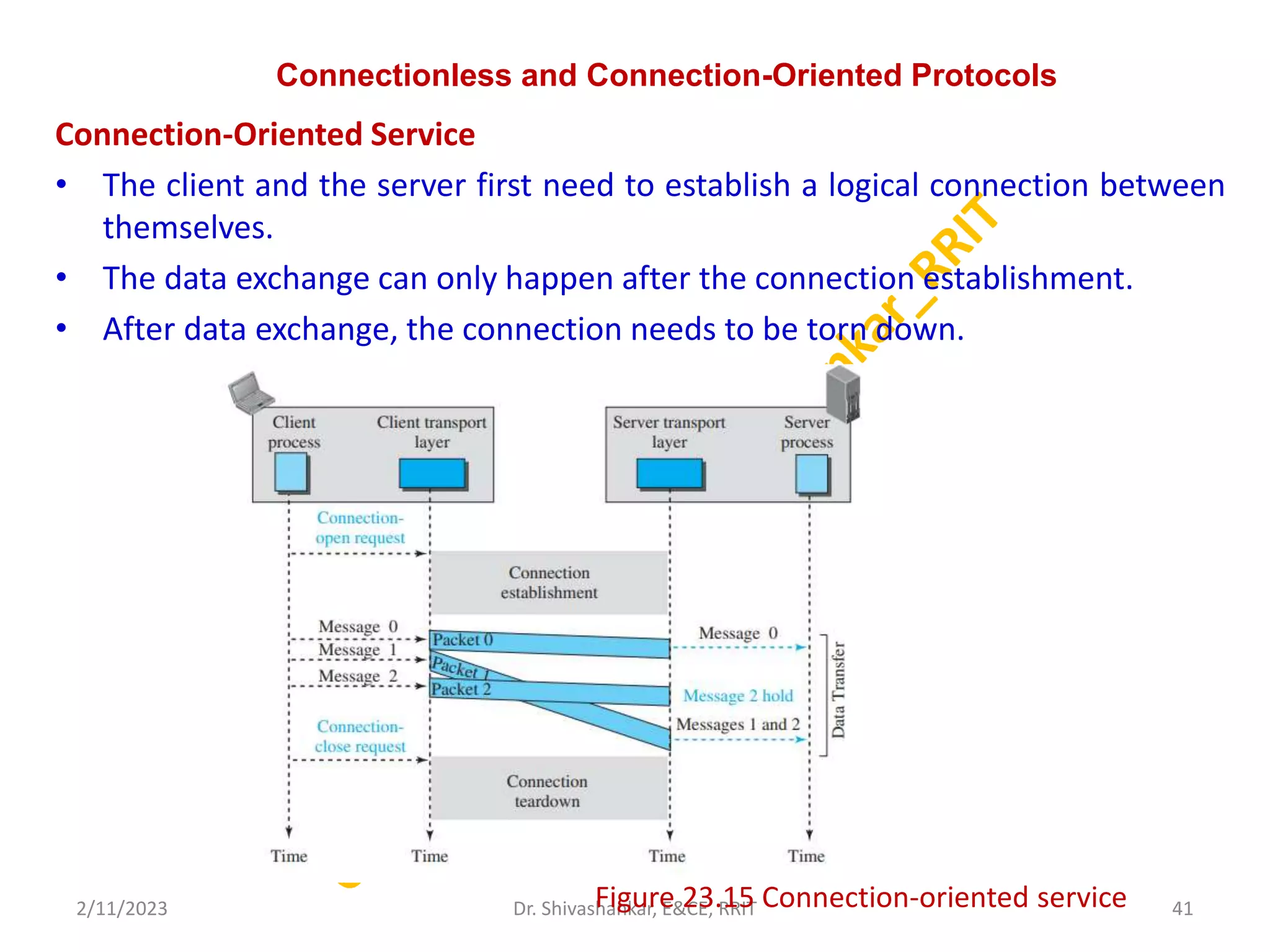
Connection-Oriented Service
• The client and the server first need to establish a logical connection between
themselves.
• The data exchange can only happen after the connection establishment.
• After data exchange, the connection needs to be torn down.
2/11/2023 41
Dr. Shivashankar, E&CE, RRIT
Figure 23.15 Connection-oriented service
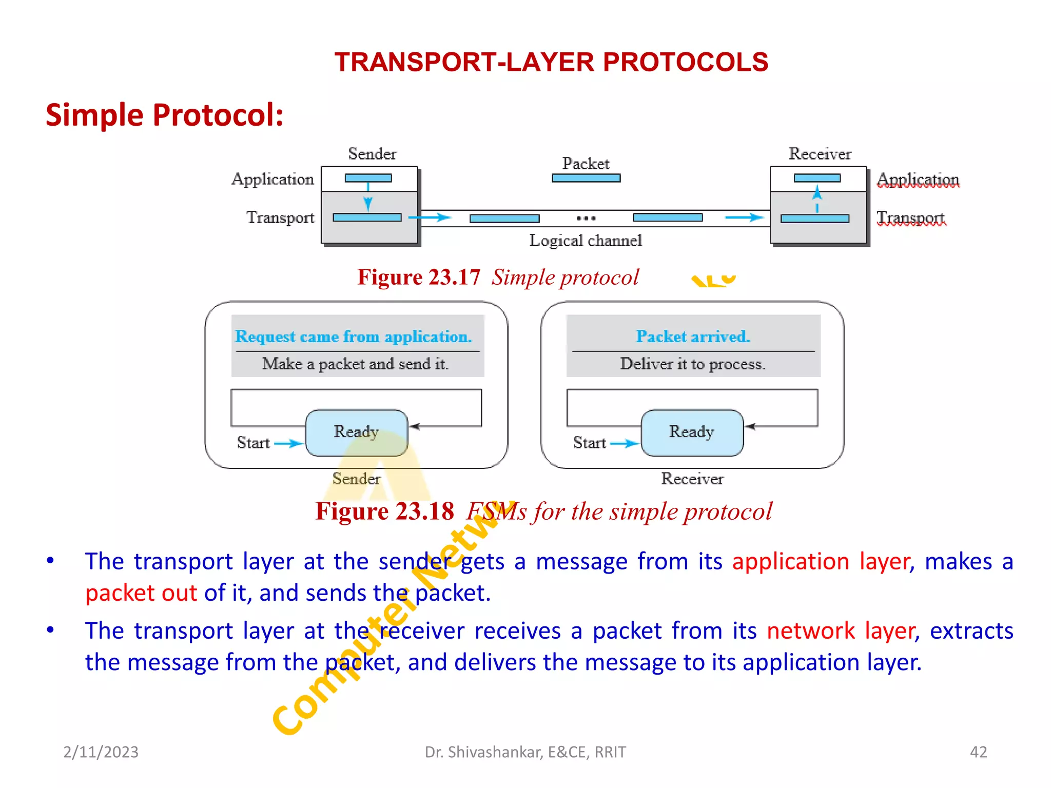
42.
TRANSPORT-LAYER PROTOCOLS
Simple Protocol:
•The transport layer at the sender gets a message from its application layer, makes a
packet out of it, and sends the packet.
• The transport layer at the receiver receives a packet from its network layer, extracts
the message from the packet, and delivers the message to its application layer.
2/11/2023 42
Dr. Shivashankar, E&CE, RRIT
Figure 23.18 FSMs for the simple protocol
Figure 23.17 Simple protocol
43.
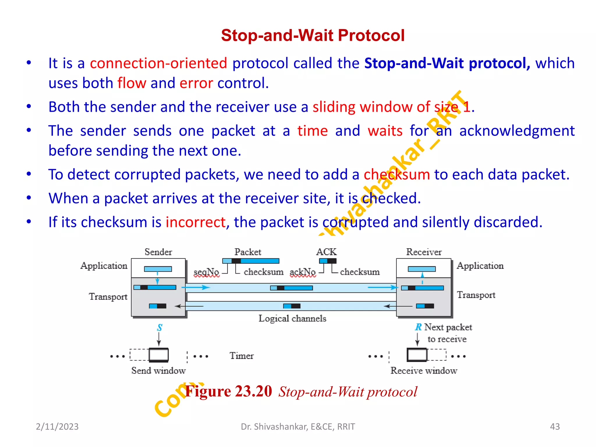
Stop-and-Wait Protocol
• Itis a connection-oriented protocol called the Stop-and-Wait protocol, which
uses both flow and error control.
• Both the sender and the receiver use a sliding window of size 1.
• The sender sends one packet at a time and waits for an acknowledgment
before sending the next one.
• To detect corrupted packets, we need to add a checksum to each data packet.
• When a packet arrives at the receiver site, it is checked.
• If its checksum is incorrect, the packet is corrupted and silently discarded.
2/11/2023 43
Dr. Shivashankar, E&CE, RRIT
Figure 23.20 Stop-and-Wait protocol
44.
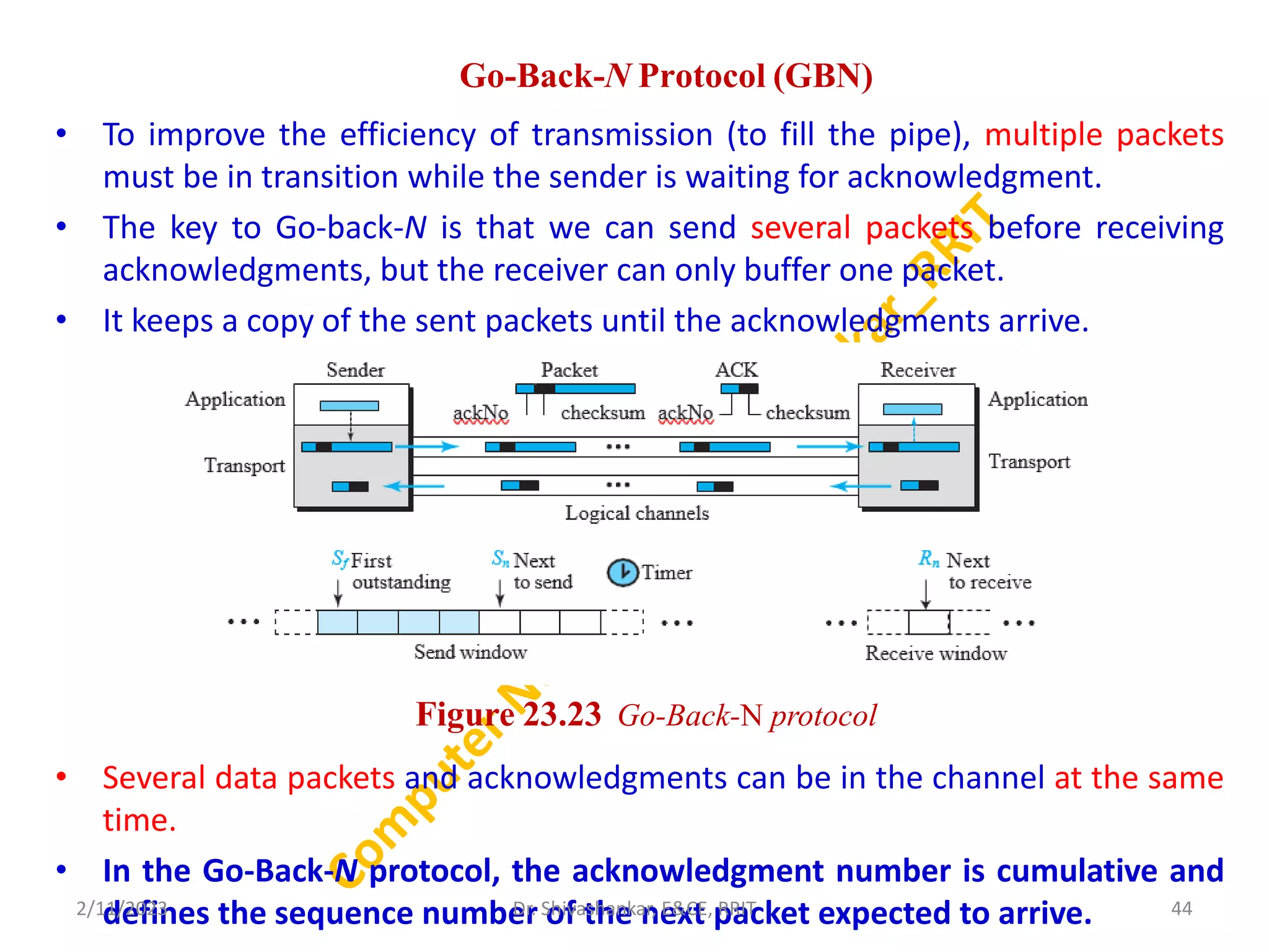
Go-Back-N Protocol (GBN)
•To improve the efficiency of transmission (to fill the pipe), multiple packets
must be in transition while the sender is waiting for acknowledgment.
• The key to Go-back-N is that we can send several packets before receiving
acknowledgments, but the receiver can only buffer one packet.
• It keeps a copy of the sent packets until the acknowledgments arrive.
• Several data packets and acknowledgments can be in the channel at the same
time.
• In the Go-Back-N protocol, the acknowledgment number is cumulative and
defines the sequence number of the next packet expected to arrive.
2/11/2023 44
Dr. Shivashankar, E&CE, RRIT
Figure 23.23 Go-Back-N protocol
45.
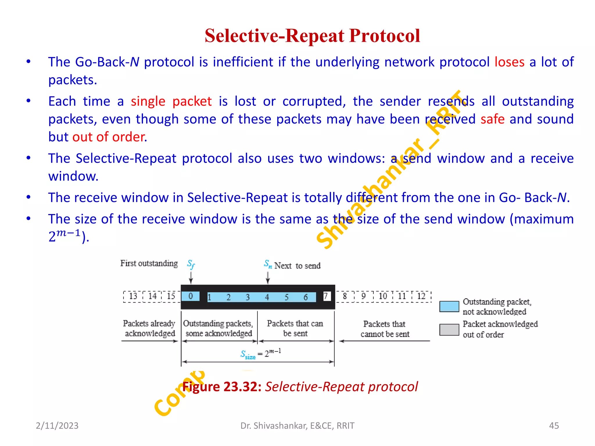
Selective-Repeat Protocol
• TheGo-Back-N protocol is inefficient if the underlying network protocol loses a lot of
packets.
• Each time a single packet is lost or corrupted, the sender resends all outstanding
packets, even though some of these packets may have been received safe and sound
but out of order.
• The Selective-Repeat protocol also uses two windows: a send window and a receive
window.
• The receive window in Selective-Repeat is totally different from the one in Go- Back-N.
• The size of the receive window is the same as the size of the send window (maximum
2𝑚−1
).
Figure 23.32: Selective-Repeat protocol
2/11/2023 45
Dr. Shivashankar, E&CE, RRIT
46.
Transport-Layer Protocols inthe Internet
USER DATAGRAM PROTOCOL
• The User Datagram Protocol (UDP) is a connectionless, unreliable
transport protocol.
• It does not add anything to the services of IP except for providing process-
to-process communication instead of host-to-host communication.
• If UDP is so powerless, why would a process want to use it? With the
disadvantages come some advantages.
• UDP is a very simple protocol using a minimum of overhead.
• If a process wants to send a small message and does not care much about
reliability, it can use UDP.
• Sending a small message using UDP takes much less interaction between
the sender and receiver than using TCP.
2/11/2023 Dr. Shivashankar, E&CE, RRIT 46
47.
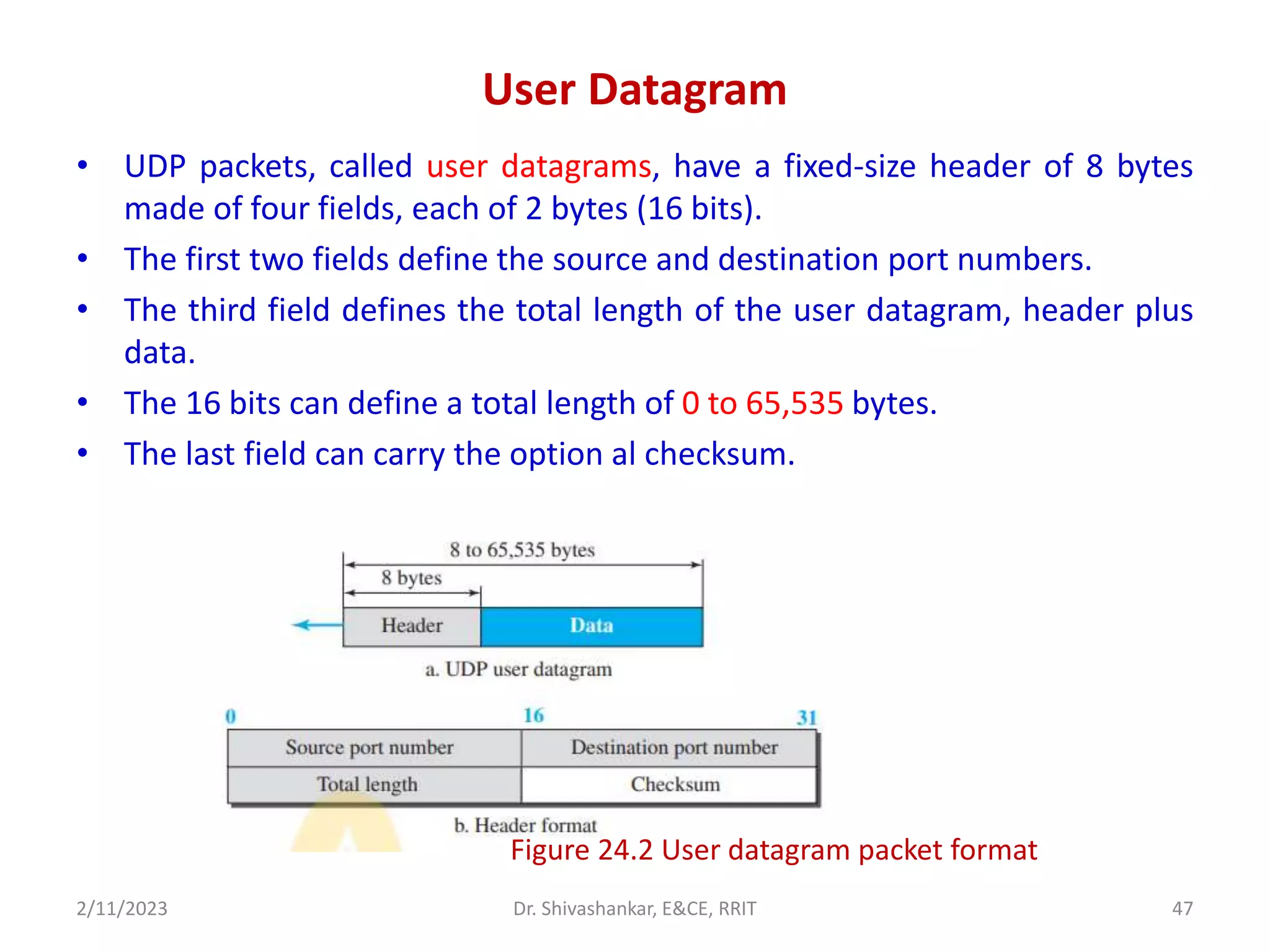
User Datagram
• UDPpackets, called user datagrams, have a fixed-size header of 8 bytes
made of four fields, each of 2 bytes (16 bits).
• The first two fields define the source and destination port numbers.
• The third field defines the total length of the user datagram, header plus
data.
• The 16 bits can define a total length of 0 to 65,535 bytes.
• The last field can carry the option al checksum.
2/11/2023 Dr. Shivashankar, E&CE, RRIT 47
Figure 24.2 User datagram packet format
48.
UDP Services
Process-to-Process Communication
•UDP provides process-to-process communication using socket addresses, a
combination of IP addresses and port numbers.
Connectionless Services
• UDP provides a connectionless service.
• Each user datagram sent by UDP is an independent datagram.
• There is no relationship between the different user datagrams even if they are
coming from the same source process and going to the same destination
program.
• The user datagrams are not numbered.
• This means that each user datagram can travel on a different path.
Flow Control
• UDP is a very simple protocol.
• There is no flow control, and hence no window mechanism.
• The receiver may overflow with incoming messages.
2/11/2023 48
Dr. Shivashankar, E&CE, RRIT
49.
Conti..
Error Control
• Thereis no error control mechanism in UDP except for the checksum.
• This means that the sender does not know if a message has been lost or duplicated.
• When the receiver detects an error through the checksum, the user datagram is
silently discarded.
• The lack of error control means that the process using UDP should provide for this
service, if needed.
Congestion Control
• Since UDP is a connectionless protocol, it does not provide congestion control.
Encapsulation and Decapsulation
• To send a message from one process to another, the UDP protocol encapsulates and
decapsulates messages.
Multiplexing and Demultiplexing
• In a host running a TCP/IP protocol suite, there is only one UDP but possibly several
processes that may want to use the services of UDP.
• To handle this situation, UDP multiplexes and demultiplexes.
2/11/2023 49
Dr. Shivashankar, E&CE, RRIT
50.
UDP Applications
• UDPis suitable for a process that requires simple request-
response communication with little concern for flow and error
control.
• UDP is suitable for a process with internal flow and error-control
mechanisms. For example, the Trivial File Transfer Protocol (TFTP)
process includes flow and error control. It can easily use UDP.
• UDP is a suitable transport protocol for multicasting.
• UDP is used for management processes such as SNMP.
• UDP is used for some route updating protocols such as Routing
Information Protocol (RIP).
• UDP is normally used for interactive real-time applications that
cannot tolerate uneven delay between sections of a received
message.
2/11/2023 50
Dr. Shivashankar, E&CE, RRIT
51.
Transmission Control Protocol(TCP)
• It is a connection-oriented, reliable protocol.
• TCP explicitly defines connection establishment, data transfer, and connection
teardown phases to provide a connection-oriented service.
• TCP uses a combination of GBN and SR protocols to provide reliability.
• To achieve this goal, TCP uses checksum (for error detection), retransmission
of lost or corrupted packets, cumulative and selective acknowledgments, and
timers.
TCP Services
Process-to-Process Communication
• As with UDP, TCP provides process-to-process communication using port
numbers.
Stream Delivery Service
• TCP, unlike UDP, is a stream-oriented protocol.
• It allows the sending process to deliver data as a stream of bytes and allows
the receiving process to obtain data as a stream of bytes.
2/11/2023 51
Dr. Shivashankar, E&CE, RRIT
52.
Full-Duplex Communication
•TCP offers full-duplex service, where data can flow in both directions at the
same time.
• Each TCP endpoint then has its own sending and receiving buffer, and
segments move in both directions.
Multiplexing and Demultiplexing
Like UDP, TCP performs multiplexing at the sender and demultiplexing at the
receiver. However, since TCP is a connection-oriented protocol, a connection
needs to be established for each pair of processes.
Connection Oriented Service
TCP, unlike UDP, is a connection-oriented protocol. When a process at site A
wants to send to and receive data from another process at site B, the following
three phases occur:
1. The two TCP’s establish a logical connection between them.
2. Data are exchanged in both directions.
3. The connection is terminated.
2/11/2023 52
Dr. Shivashankar, E&CE, RRIT
53.
TCP Features
Numbering System
•Although the TCP software keeps track of the segments being transmitted or
received, there is no field for a segment number value in the segment header.
• Instead, there are two fields, called the sequence number and the
acknowledgment number.
• These two fields refer to a byte number and not a segment number.
Byte Number
• The bytes of data being transferred in each connection are numbered by TCP.
• TCP chooses an arbitrary number between 0 and 232
− 1 for the number of
the first byte.
Sequence Number
The sequence number, in each direction, is defined as follows:
1. The sequence number of the first segment is the ISN (initial sequence
number), which is a random number.
2. The sequence number of any other segment is the sequence number of the
previous segment plus the number of bytes (real or imaginary) carried by the
previous segment.
2/11/2023 53
Dr. Shivashankar, E&CE, RRIT
54.
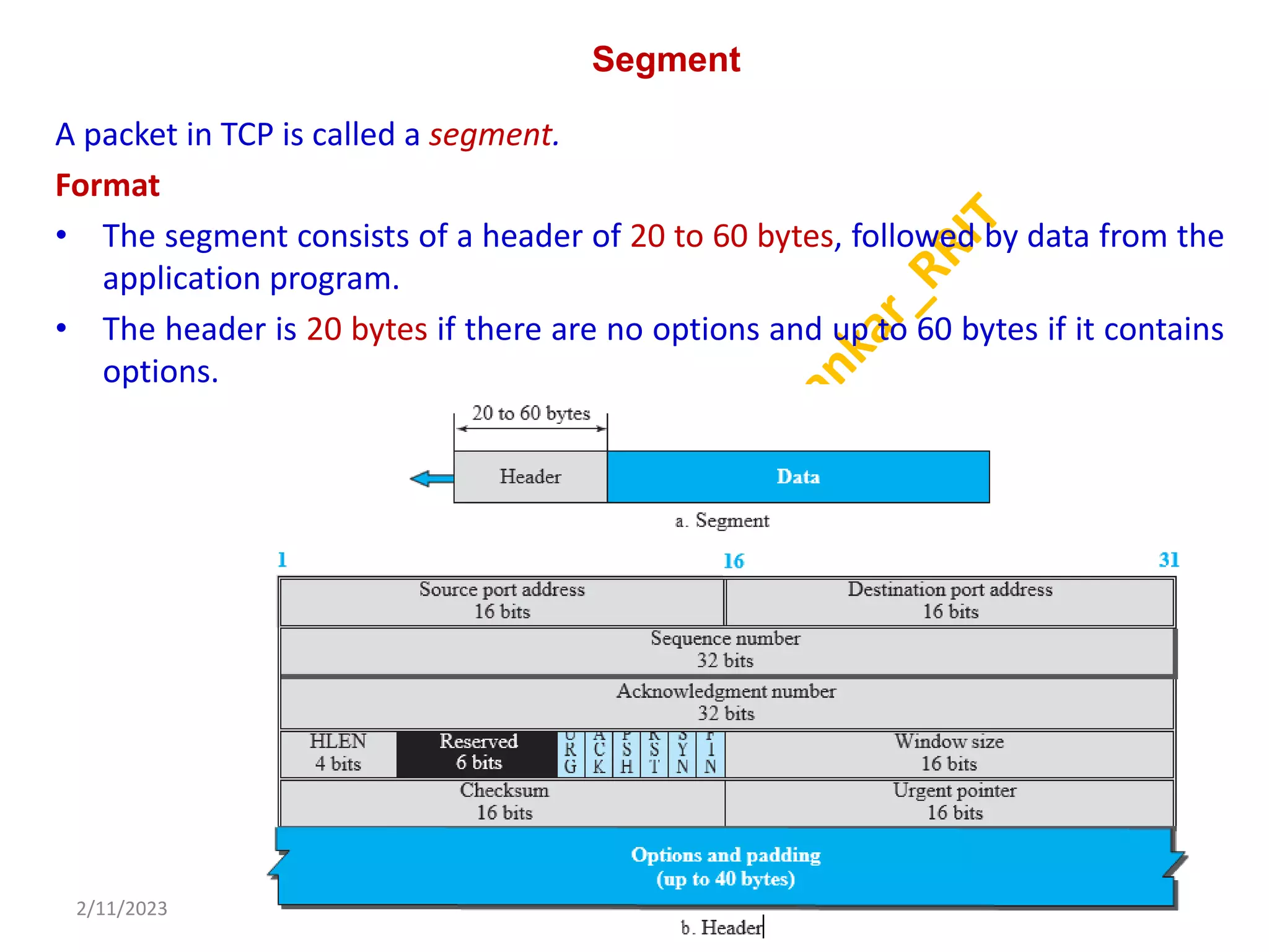
Segment
A packet inTCP is called a segment.
Format
• The segment consists of a header of 20 to 60 bytes, followed by data from the
application program.
• The header is 20 bytes if there are no options and up to 60 bytes if it contains
options.
2/11/2023 54
Dr. Shivashankar, E&CE, RRIT
55.
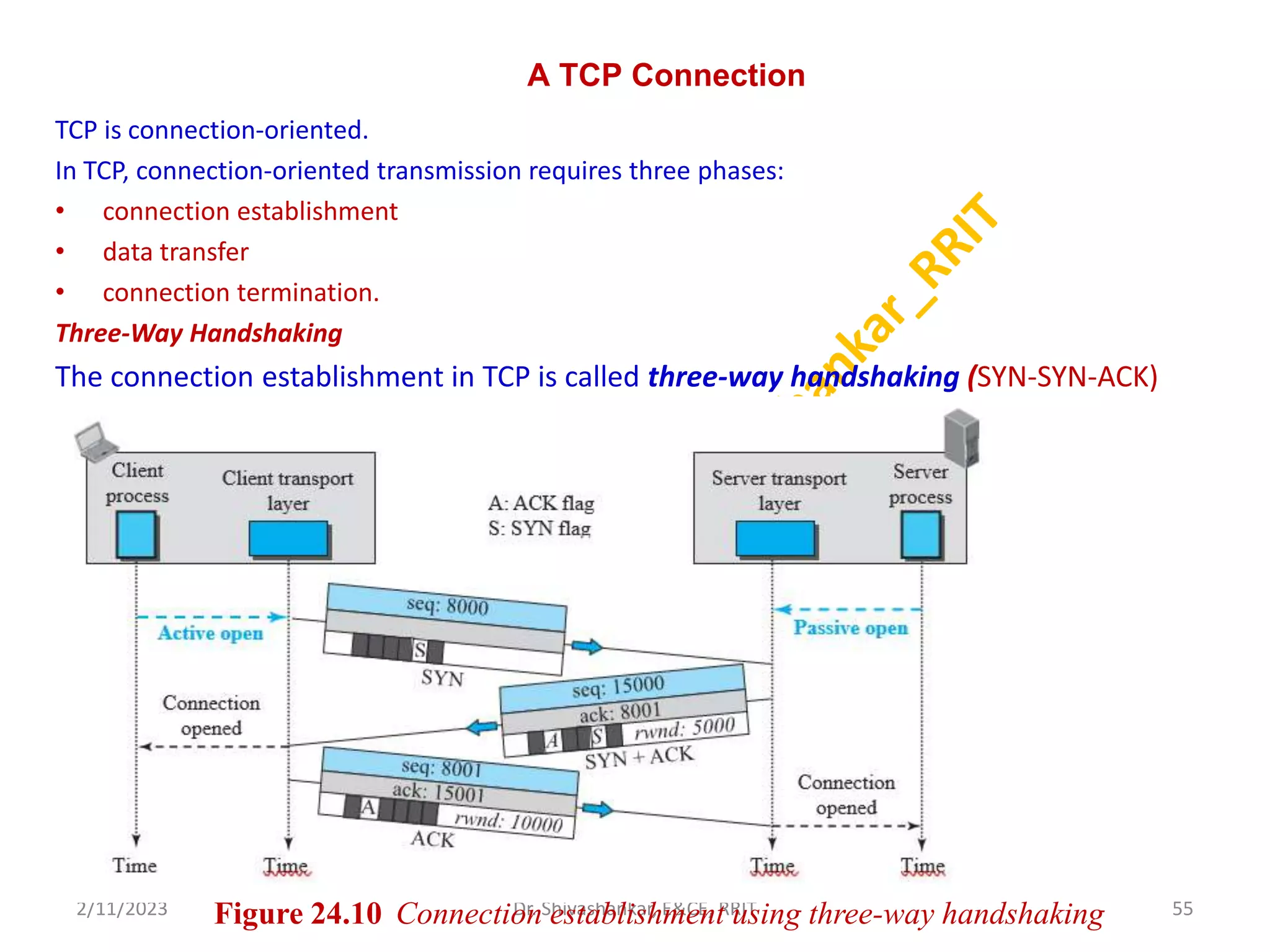
A TCP Connection
TCPis connection-oriented.
In TCP, connection-oriented transmission requires three phases:
• connection establishment
• data transfer
• connection termination.
Three-Way Handshaking
The connection establishment in TCP is called three-way handshaking (SYN-SYN-ACK)
2/11/2023 55
Dr. Shivashankar, E&CE, RRIT
Figure 24.10 Connection establishment using three-way handshaking
56.
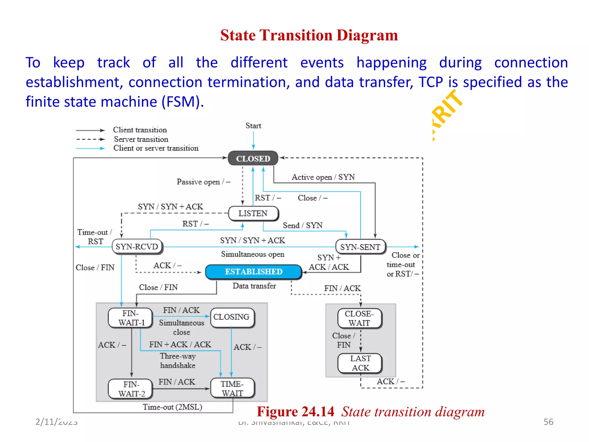
State Transition Diagram
Tokeep track of all the different events happening during connection
establishment, connection termination, and data transfer, TCP is specified as the
finite state machine (FSM).
2/11/2023 56
Dr. Shivashankar, E&CE, RRIT
Figure 24.14 State transition diagram
57.
Windows in TCP
•Each window serves an important purpose for the flow of data between the
TCP sender and TCP receiver.
Send Window
The window size is 100 bytes.
• The send window in TCP is similar to the one used with the Selective-Repeat
protocol.
Receive Window
• The window size is 100 bytes.
• The receive window size determines the number of bytes that the receive
window can accept from the sender before being overwhelmed (flow control).
2/11/2023 57
Dr. Shivashankar, E&CE, RRIT
58.
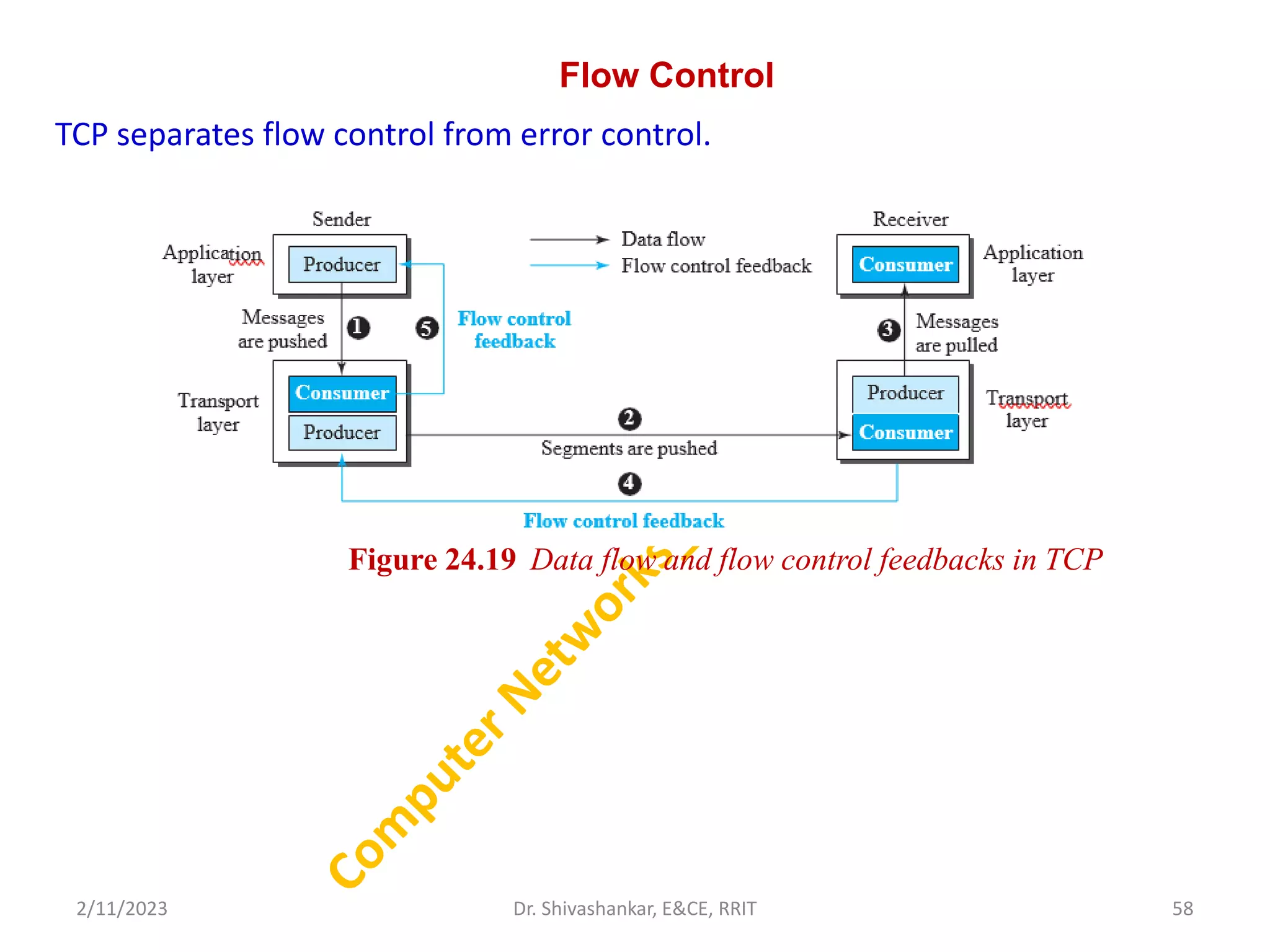
Flow Control
TCP separatesflow control from error control.
2/11/2023 58
Dr. Shivashankar, E&CE, RRIT
Figure 24.19 Data flow and flow control feedbacks in TCP
59.
Error Control
• TCPis a reliable transport-layer protocol.
• An application program that delivers a stream of data to TCP relies on TCP to
deliver the entire stream to the application program on the other end in
order, without error, and without any part lost or duplicated.
• TCP provides reliability using error control.
• Error control includes mechanisms for detecting and resending corrupted
segments, resending lost segments, storing out-of-order segments until
missing segments arrive, and detecting and discarding duplicated segments.
• Error control in TCP is achieved through the use of three simple tools:
checksum,
acknowledgment, and
time-out.
2/11/2023 59
Dr. Shivashankar, E&CE, RRIT
60.
Checksum
• Each segmentincludes a checksum field, used to check for a corrupted segment.
• If a segment is corrupted, as detected by an invalid checksum, the segment is dis-
carded by the destination TCP and is considered as lost.
• TCP uses a 16-bit checksum that is mandatory in every segment.
Acknowledgment
• TCP uses acknowledgments to confirm the receipt of data segments.
• Control segments that carry no data, but consume a sequence number, are also
acknowledged.
• ACK segments are never acknowledged.
Acknowledgment Type
Cumulative Acknowledgment (ACK):
• The 32-bit ACK field in the TCP header is used for cumulative acknowledgments, and its
value is valid only when the ACK flag bit is set to 1.
Selective Acknowledgment (SACK):
• A SACK does not replace an ACK, but reports additional information to the sender.
• A SACK reports a block of bytes that is out of order, and also a block of bytes that is
duplicated, i.e., received more than once.
2/11/2023 60
Dr. Shivashankar, E&CE, RRIT
61.
TCP Congestion Control
CongestionWindow
• To control the number of segments to transmit, TCP uses another variable
called a congestion window, cwnd.
• The receiver window, rwnd variable together define the size of the send
window in TCP.
• The first is related to the congestion in the middle (network); the second is
related to the congestion at the end.
• Actual window size 5 minimum (rwnd, cwnd )
Congestion Detection
• TCP sender uses only one feedback from the other end to detect congestion:
ACKs.
• The lack of regular, timely receipt of ACKs, which results in a time-out, is the
sign of a strong congestion; the receiving of three duplicate ACKs is the sign of
a weak congestion in the network.
2/11/2023 61
Dr. Shivashankar, E&CE, RRIT
62.
Module 5
Application Layer
•The application layer provides services to the user.
• Communication is provided using a logical connection, which
means that the two application layers assume that there is an
imaginary direct connection through which they can send and
receive the messages.
• Application Layer provides a facility by which users can forward
several emails and it also provides a storage facility.
• This layer allows users to access, retrieve and manage files in a
remote computer.
• It allows users to log on as a remote host.
2/11/2023 62
Dr. Shivashankar, E&CE, RRIT
63.
Providing Services
• TheInternet was originally designed for the same purpose: to provide service
to users around the world.
• New protocols can be added or some protocols can be removed or replaced
by the Internet authorities.
• Since the application layer is the only layer that provides services to the
Internet user, it allows new application protocols to be easily added to the
Internet.
Standard Application-Layer Protocols
• There are several application-layer protocols that have been standardized and
documented by the Internet authority.
• Each standard protocol is a pair of computer programs that interact with the
user and the transport layer to provide a specific service to the user.
• Ex: Telnet, FTP, TFTP, SMTP, SNMP, DNS, DHCP.
Nonstandard Application-Layer Protocols
• A programmer can create a nonstandard application-layer program.
• It is the creation of a nonstandard (proprietary) protocol, which does not even
need the approval of the Internet authorities if privately used.
2/11/2023 63
Dr. Shivashankar, E&CE, RRIT
64.
Application-Layer Paradigms
Two paradigmshave been developed during the lifetime of the Internet:
1. the client-server paradigm
2. the peer-to-peer paradigm.
Traditional Paradigm: Client-Server
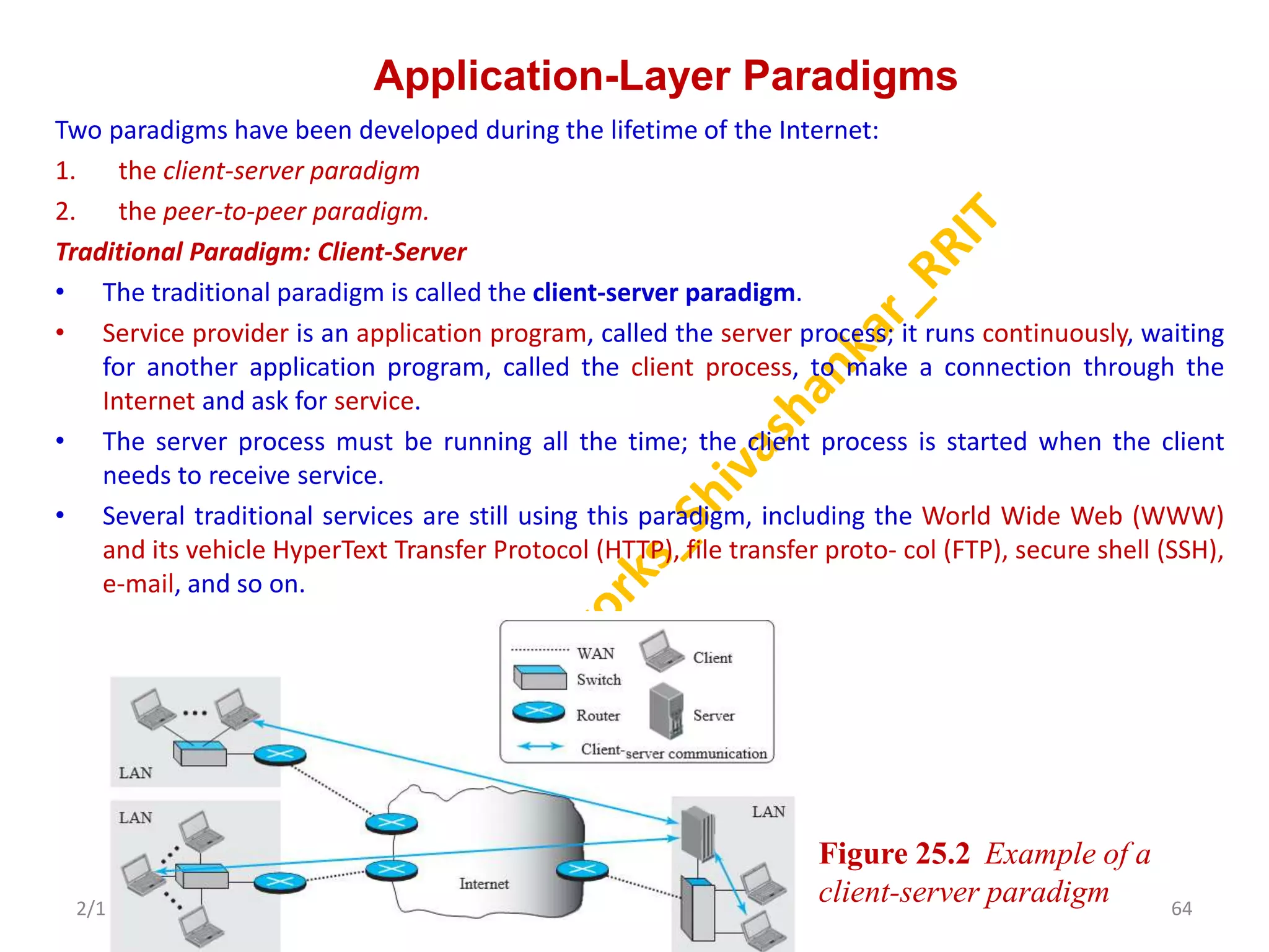
• The traditional paradigm is called the client-server paradigm.
• Service provider is an application program, called the server process; it runs continuously, waiting
for another application program, called the client process, to make a connection through the
Internet and ask for service.
• The server process must be running all the time; the client process is started when the client
needs to receive service.
• Several traditional services are still using this paradigm, including the World Wide Web (WWW)
and its vehicle HyperText Transfer Protocol (HTTP), file transfer proto- col (FTP), secure shell (SSH),
e-mail, and so on.
2/11/2023 64
Dr. Shivashankar, E&CE, RRIT
Figure 25.2 Example of a
client-server paradigm
65.
Peer-to-Peer
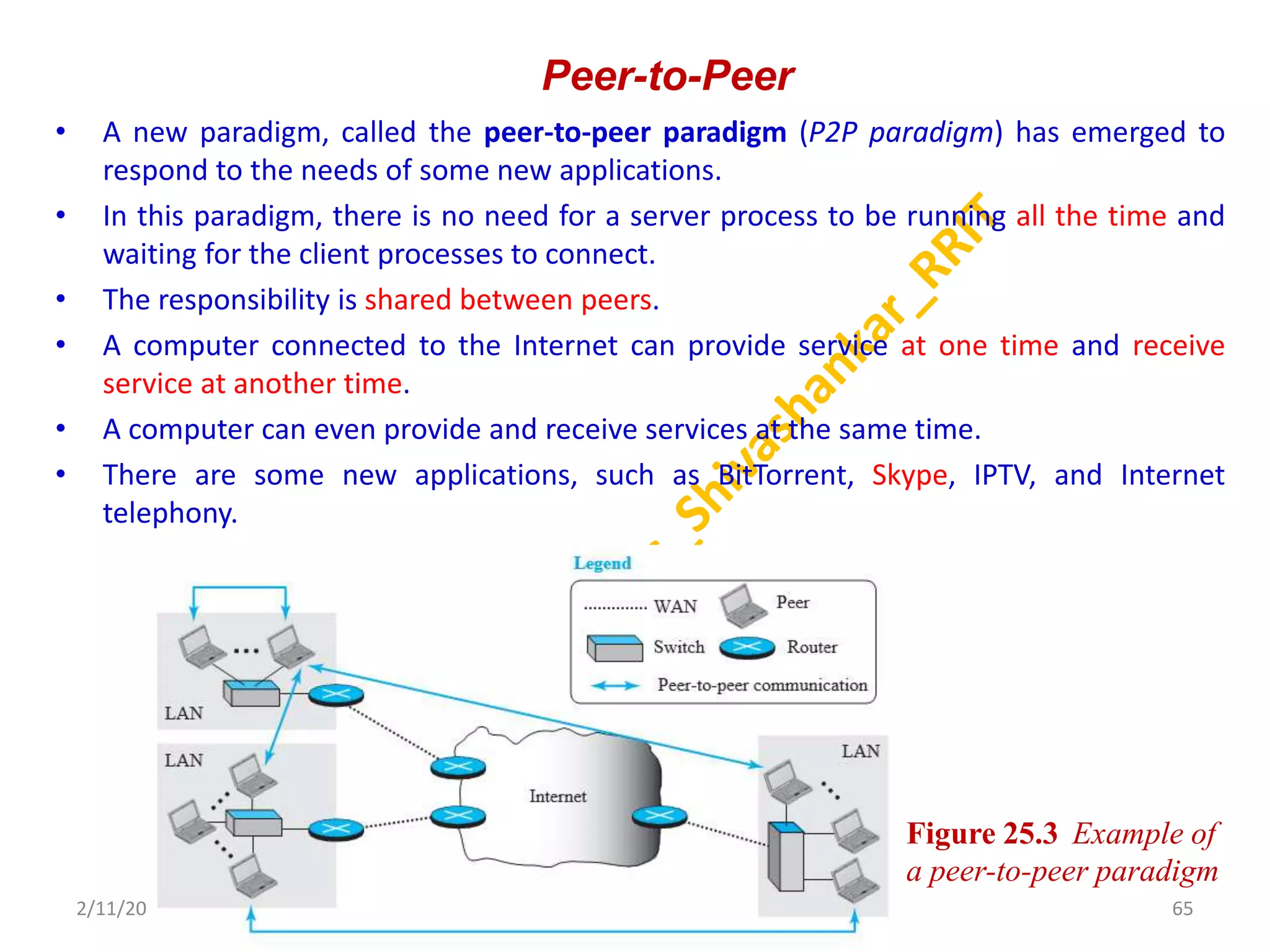
• A newparadigm, called the peer-to-peer paradigm (P2P paradigm) has emerged to
respond to the needs of some new applications.
• In this paradigm, there is no need for a server process to be running all the time and
waiting for the client processes to connect.
• The responsibility is shared between peers.
• A computer connected to the Internet can provide service at one time and receive
service at another time.
• A computer can even provide and receive services at the same time.
• There are some new applications, such as BitTorrent, Skype, IPTV, and Internet
telephony.
2/11/2023 65
Dr. Shivashankar, E&CE, RRIT
Figure 25.3 Example of
a peer-to-peer paradigm
66.
Mixed Paradigm
• Anapplication may choose to use a mixture of the two
paradigms by combining the advantages of both.
• For example, a light-load client-server communication can be
used to find the address of the peer that can offer a service.
• When the address of the peer is found, the actual service can be
received from the peer by using the peer-to- peer paradigm.
2/11/2023 66
Dr. Shivashankar, E&CE, RRIT
67.
WORLD WIDE WEB
•The idea of the Web was first proposed by Tim Berners-Lee in 1989 at CERN,
the European Organization for Nuclear Research, to allow several researchers
at different locations throughout Europe to access each others’ researches.
• The commercial Web started in the early 1990s.
• The Web today is a repository of information in which the documents, called
web pages, are distributed all over the world and related documents are
linked together.
• The popularity and growth of the Web can be related to two terms in the
above statement: distributed and linked.
• Linking allows one web page to refer to another web page stored in another
server somewhere else in the world.
• The linking of web pages was achieved using a concept called hypertext,
• The WWW today is a distributed client-server service, in which a client using a browser
can access a service using a server. However, the service provided is distributed over
many locations called sites.
• Each site holds one or more web pages.
2/11/2023 67
Dr. Shivashankar, E&CE, RRIT
68.
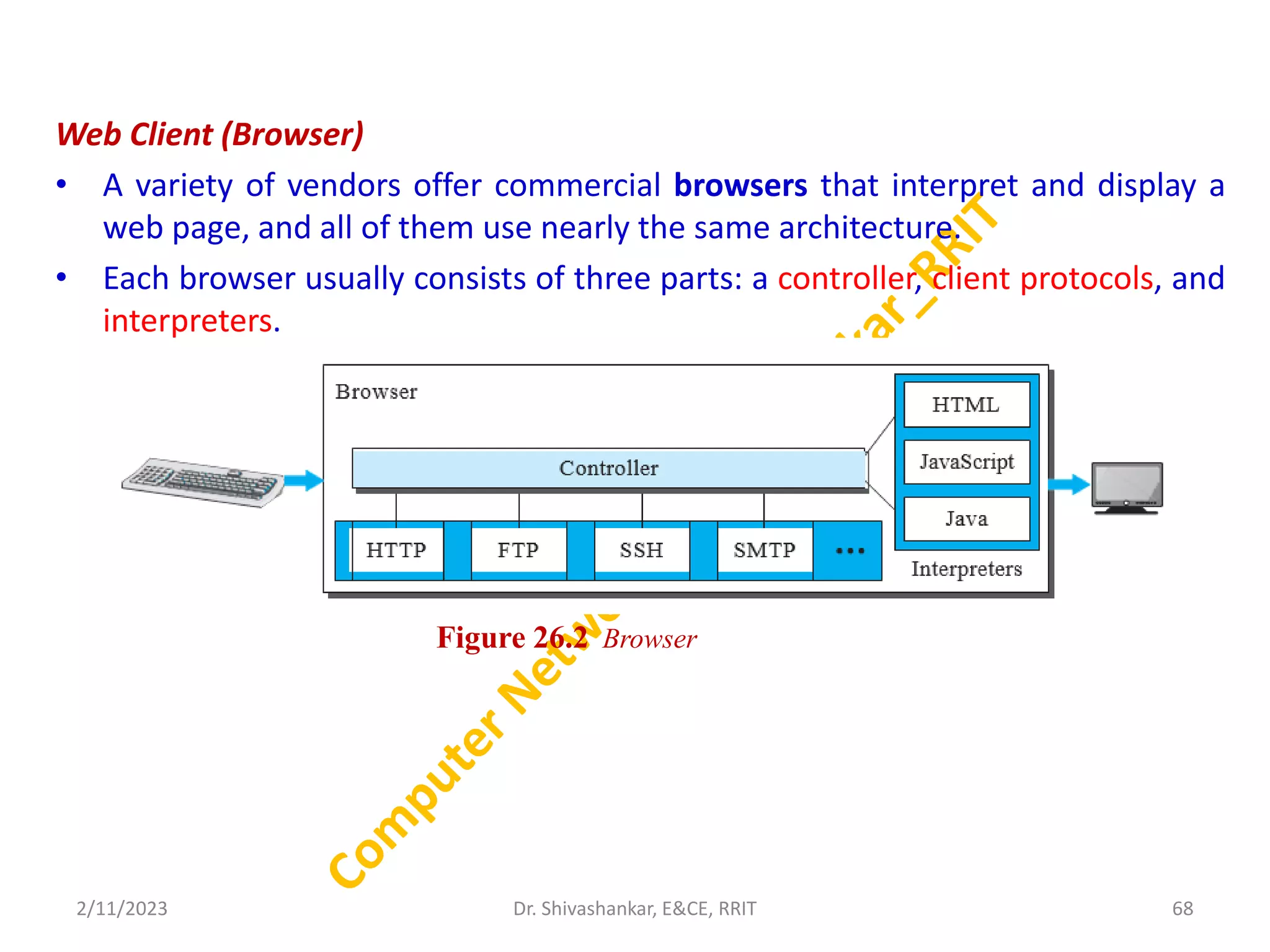
Web Client (Browser)
•A variety of vendors offer commercial browsers that interpret and display a
web page, and all of them use nearly the same architecture.
• Each browser usually consists of three parts: a controller, client protocols, and
interpreters.
2/11/2023 68
Dr. Shivashankar, E&CE, RRIT
Figure 26.2 Browser
69.
Web Server
• Aweb server is software and hardware that uses HTTP and other protocols to
respond to client requests made over the World Wide Web.
• The main job of a web server is to display website content through storing,
processing and delivering webpages to users.
• Besides HTTP, web servers also support SMTP and FTP, used for email, file
transfer and storage.
• Web server hardware is connected to the internet and allows data to be
exchanged with other connected devices, while web server software controls
how a user accesses hosted files.
• All computers that host websites must have web server software.
Uniform Resource Locator (URL):
A URL (Uniform Resource Locator) is a unique identifier used to locate a resource
on the Internet.
It is also referred to as a web address.
Ex: https://www.rrit.ac.in
2/11/2023 69
Dr. Shivashankar, E&CE, RRIT
70.
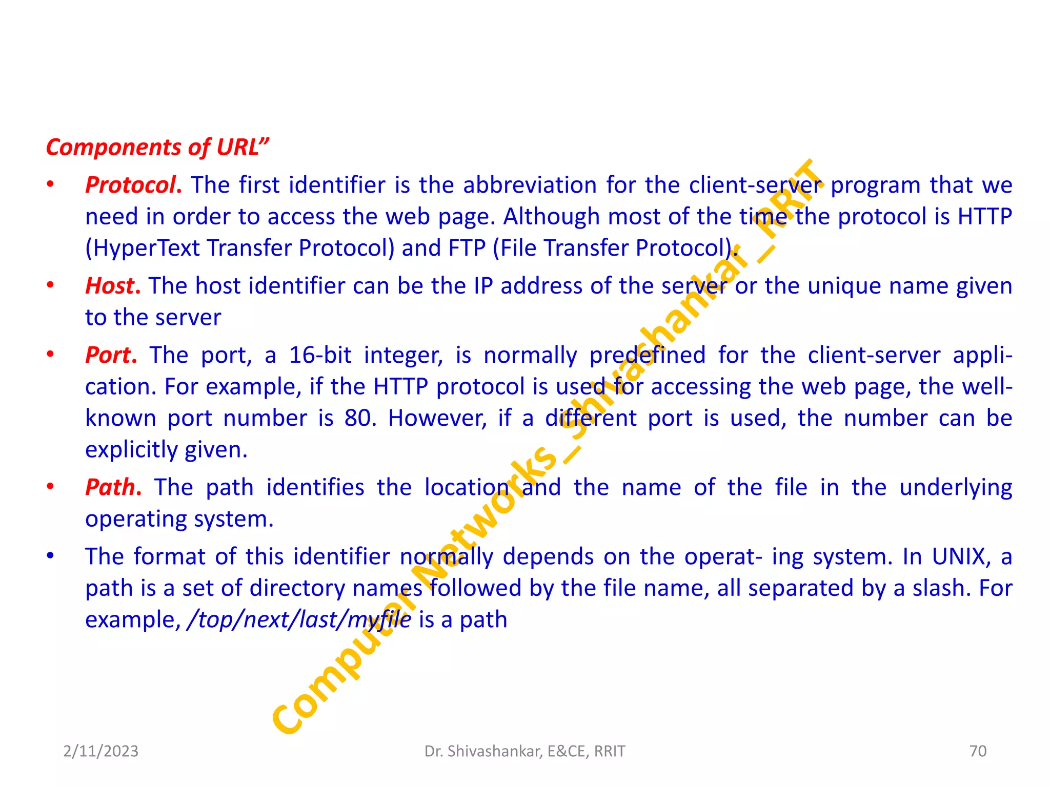
Components of URL”
•Protocol. The first identifier is the abbreviation for the client-server program that we
need in order to access the web page. Although most of the time the protocol is HTTP
(HyperText Transfer Protocol) and FTP (File Transfer Protocol).
• Host. The host identifier can be the IP address of the server or the unique name given
to the server
• Port. The port, a 16-bit integer, is normally predefined for the client-server appli-
cation. For example, if the HTTP protocol is used for accessing the web page, the well-
known port number is 80. However, if a different port is used, the number can be
explicitly given.
• Path. The path identifies the location and the name of the file in the underlying
operating system.
• The format of this identifier normally depends on the operat- ing system. In UNIX, a
path is a set of directory names followed by the file name, all separated by a slash. For
example, /top/next/last/myfile is a path
2/11/2023 70
Dr. Shivashankar, E&CE, RRIT
71.
HyperText Transfer Protocol(HTTP)
• It is a protocol used to access the data on the World Wide Web (www).
• The HTTP protocol can be used to transfer the data in the form of plain text,
hypertext, audio, video, and so on.
• HTTP is similar to the FTP as it also transfers the files from one host to another
host. But, HTTP is simpler than FTP as HTTP uses only one connection, i.e., no
control connection to transfer the files.
Nonpersistent versus Persistent Connections
• Nonpersistent Connections
• In a nonpersistent connection, one TCP connection is made for each
request/response. The following lists the steps in this strategy:
• The client opens a TCP connection and sends a request.
• The server sends the response and closes the connection.
• The client reads the data until it encounters an end-of-file
marker
2/11/2023 71
Dr. Shivashankar, E&CE, RRIT
72.
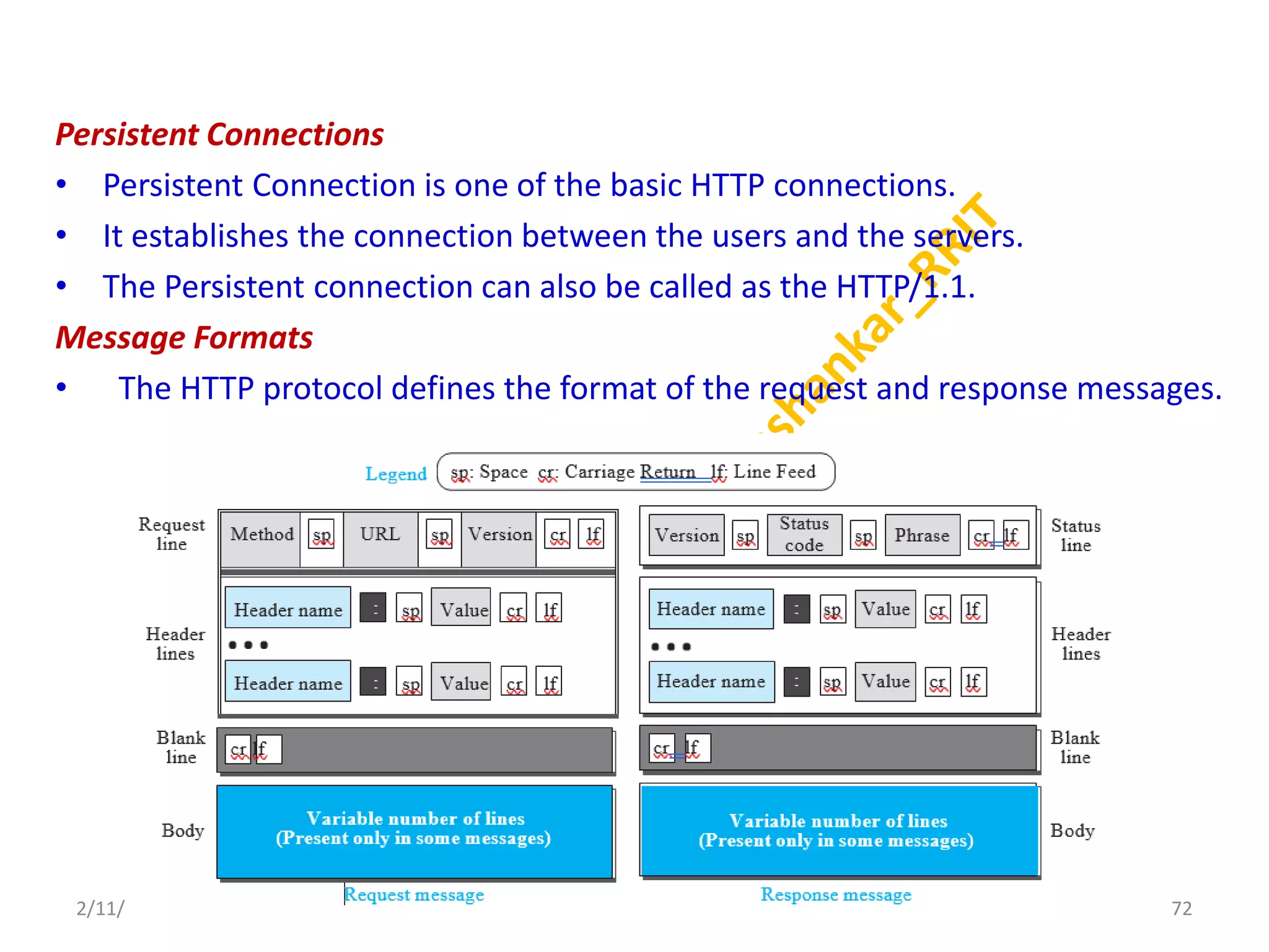
Persistent Connections
• PersistentConnection is one of the basic HTTP connections.
• It establishes the connection between the users and the servers.
• The Persistent connection can also be called as the HTTP/1.1.
Message Formats
• The HTTP protocol defines the format of the request and response messages.
2/11/2023 72
Dr. Shivashankar, E&CE, RRIT
73.
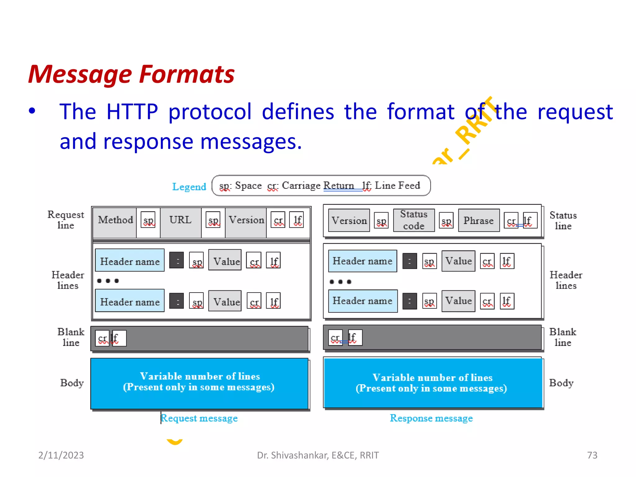
Message Formats
• TheHTTP protocol defines the format of the request
and response messages.
2/11/2023 73
Dr. Shivashankar, E&CE, RRIT
74.
HTTP Security
• HTTPdoes not provide security.
• HTTP can be run over the Secure Socket Layer (SSL).
• In this case, HTTP is referred to as HTTPS. HTTPS
provides confidentiality, client and server
authentication, and data integrity.
2/11/2023 74
Dr. Shivashankar, E&CE, RRIT
75.
Web Caching: ProxyServers
• HTTP supports proxy servers.
• A proxy server is a computer that keeps copies of responses to recent
requests.
• The HTTP client sends a request to the proxy server. The proxy server checks
its cache.
• If the response is not stored in the cache, the proxy server sends the request
to the corresponding server. Incoming responses are sent to the proxy server
and stored for future requests from other clients.
• The proxy server reduces the load on the original server, decreases traffic, and
improves latency.
• To use the proxy server, the client must be configured to access the proxy
instead of the target server.
2/11/2023 75
Dr. Shivashankar, E&CE, RRIT
76.
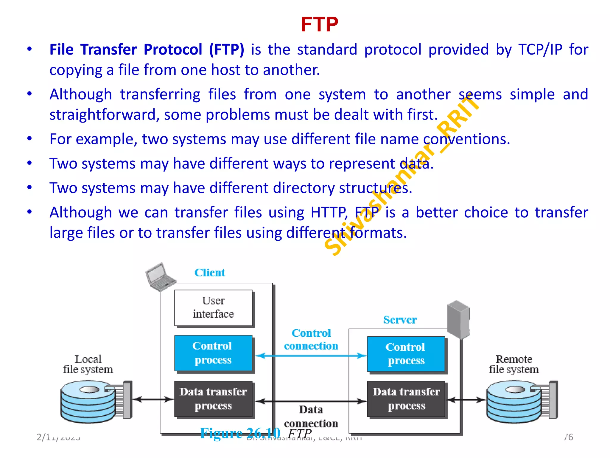
FTP
• File TransferProtocol (FTP) is the standard protocol provided by TCP/IP for
copying a file from one host to another.
• Although transferring files from one system to another seems simple and
straightforward, some problems must be dealt with first.
• For example, two systems may use different file name conventions.
• Two systems may have different ways to represent data.
• Two systems may have different directory structures.
• Although we can transfer files using HTTP, FTP is a better choice to transfer
large files or to transfer files using different formats.
2/11/2023 76
Dr. Shivashankar, E&CE, RRIT
Figure 26.10 FTP
77.
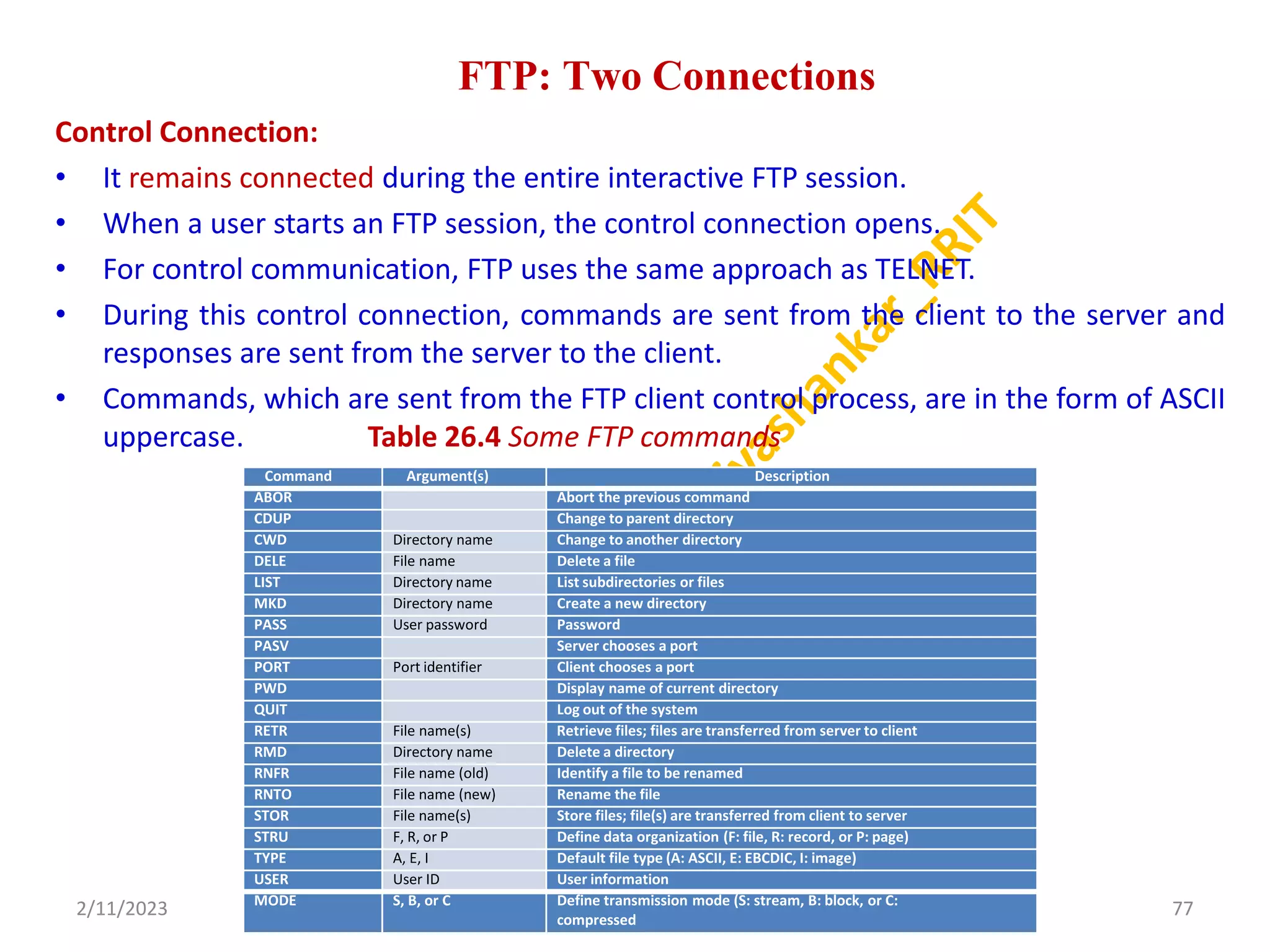
FTP: Two Connections
ControlConnection:
• It remains connected during the entire interactive FTP session.
• When a user starts an FTP session, the control connection opens.
• For control communication, FTP uses the same approach as TELNET.
• During this control connection, commands are sent from the client to the server and
responses are sent from the server to the client.
• Commands, which are sent from the FTP client control process, are in the form of ASCII
uppercase. Table 26.4 Some FTP commands
2/11/2023 77
Dr. Shivashankar, E&CE, RRIT
Command Argument(s) Description
ABOR Abort the previous command
CDUP Change to parent directory
CWD Directory name Change to another directory
DELE File name Delete a file
LIST Directory name List subdirectories or files
MKD Directory name Create a new directory
PASS User password Password
PASV Server chooses a port
PORT Port identifier Client chooses a port
PWD Display name of current directory
QUIT Log out of the system
RETR File name(s) Retrieve files; files are transferred from server to client
RMD Directory name Delete a directory
RNFR File name (old) Identify a file to be renamed
RNTO File name (new) Rename the file
STOR File name(s) Store files; file(s) are transferred from client to server
STRU F, R, or P Define data organization (F: file, R: record, or P: page)
TYPE A, E, I Default file type (A: ASCII, E: EBCDIC, I: image)
USER User ID User information
MODE S, B, or C Define transmission mode (S: stream, B: block, or C:
compressed
78.
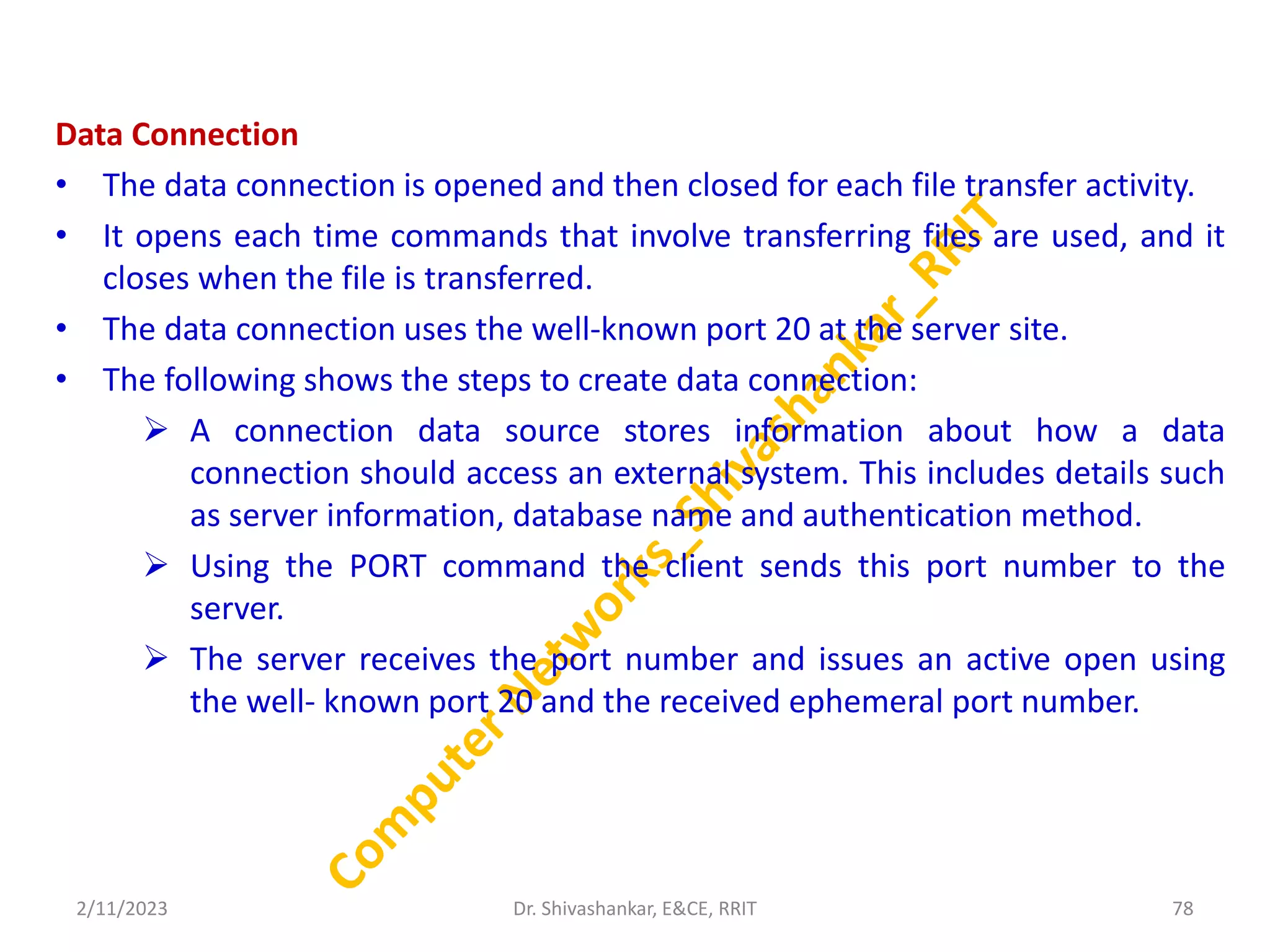
Data Connection
• Thedata connection is opened and then closed for each file transfer activity.
• It opens each time commands that involve transferring files are used, and it
closes when the file is transferred.
• The data connection uses the well-known port 20 at the server site.
• The following shows the steps to create data connection:
A connection data source stores information about how a data
connection should access an external system. This includes details such
as server information, database name and authentication method.
Using the PORT command the client sends this port number to the
server.
The server receives the port number and issues an active open using
the well- known port 20 and the received ephemeral port number.
2/11/2023 78
Dr. Shivashankar, E&CE, RRIT
79.
ELECTRONIC MAIL
• ElectronicMail (e-mail) is one of most widely used services of Internet.
• In an application such as HTTP or FTP, the server program is running all the
time, waiting for a request from a client.
• When the request arrives, the server provides the service.
• There is a request and there is a response.
• Message in mail not only contain text, but it also contains images, audio and
videos data.
• The person who is sending mail is called sender and person who receives mail
is called recipient.
• Architecture
2/11/2023 79
Dr. Shivashankar, E&CE, RRIT
80.
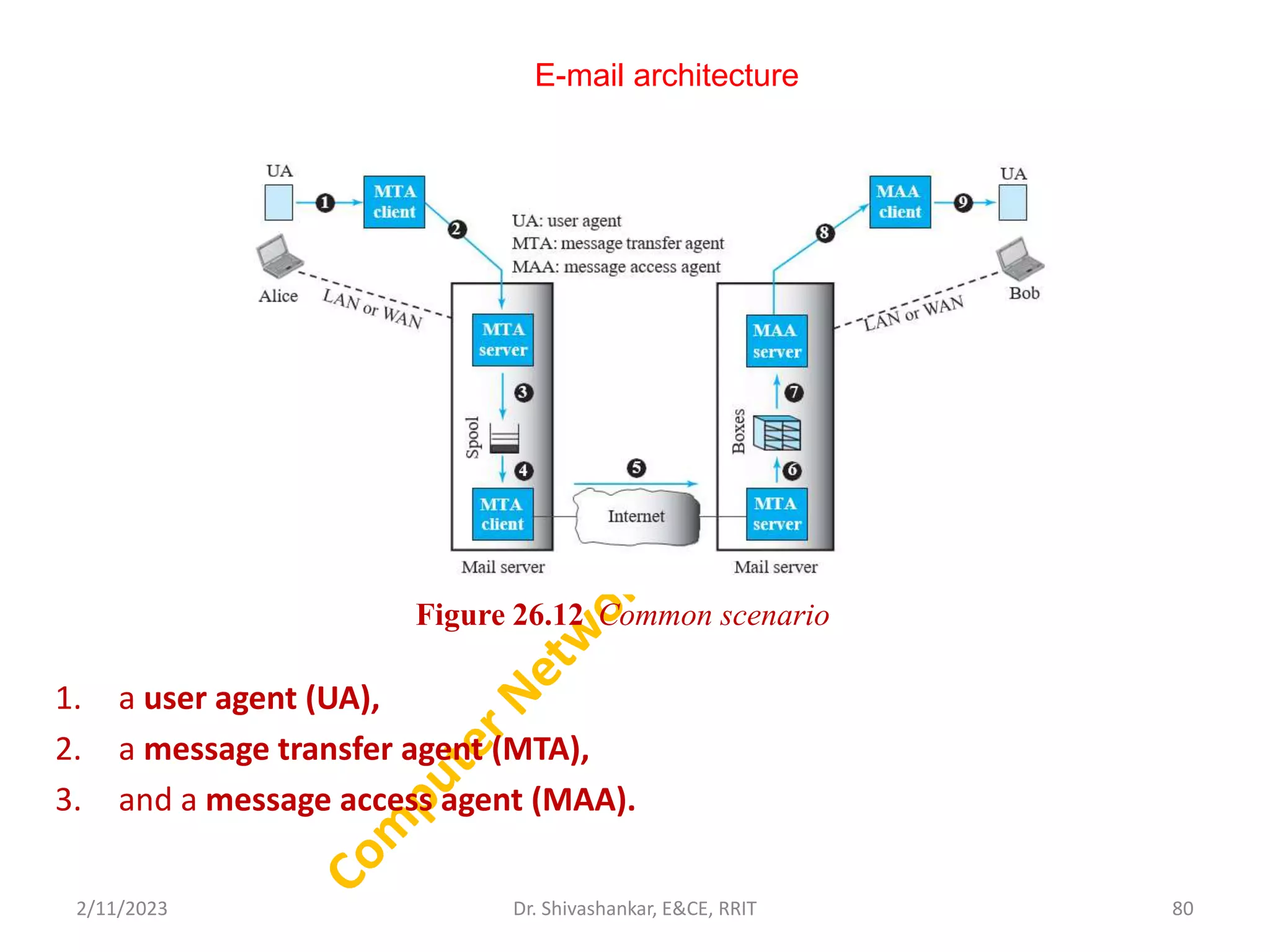
E-mail architecture
1. auser agent (UA),
2. a message transfer agent (MTA),
3. and a message access agent (MAA).
2/11/2023 80
Dr. Shivashankar, E&CE, RRIT
Figure 26.12 Common scenario
81.
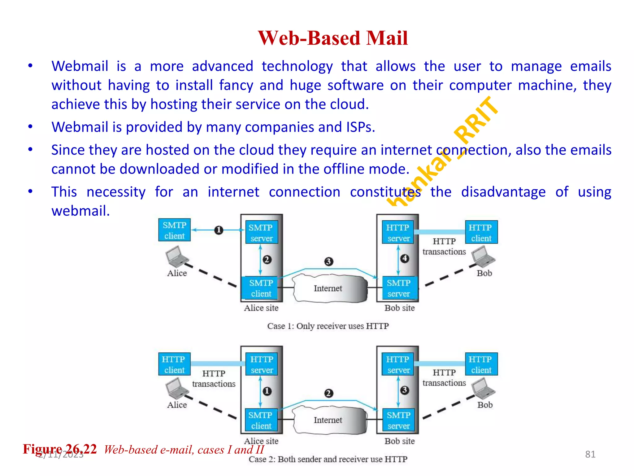
Web-Based Mail
• Webmailis a more advanced technology that allows the user to manage emails
without having to install fancy and huge software on their computer machine, they
achieve this by hosting their service on the cloud.
• Webmail is provided by many companies and ISPs.
• Since they are hosted on the cloud they require an internet connection, also the emails
cannot be downloaded or modified in the offline mode.
• This necessity for an internet connection constitutes the disadvantage of using
webmail.
2/11/2023 81
Dr. Shivashankar, E&CE, RRIT
Figure 26.22 Web-based e-mail, cases I and II
82.
E-Mail Security
• e-mailexchanges can be secured using two
application-layer securities designed in particular for e-
mail systems.
• Two of these protocols, Pretty Good Privacy (PGP) and
Secure/Multipurpose Internet Mail Extensions
(S/MIME)
2/11/2023 82
Dr. Shivashankar, E&CE, RRIT
83.
TELNET
• TELNET standsfor Teletype Network.
• It is a type of protocol that enables one computer to connect to local
computer.
• It is a used as a standard TCP/IP protocol for virtual terminal service which is
given by ISO.
• Computer which starts connection known as the local computer. Computer
which is being connected to i.e. which accepts the connection known
as remote computer. When the connection is established between local and
remote computer.
• Telnet operates on client/server principle.
• Local computer uses telnet client program and the remote computers uses
telnet server program.
• Telnet can be used for a variety of activities on a server, including editing files,
running various programs and checking email.
2/11/2023 83
Dr. Shivashankar, E&CE, RRIT
84.
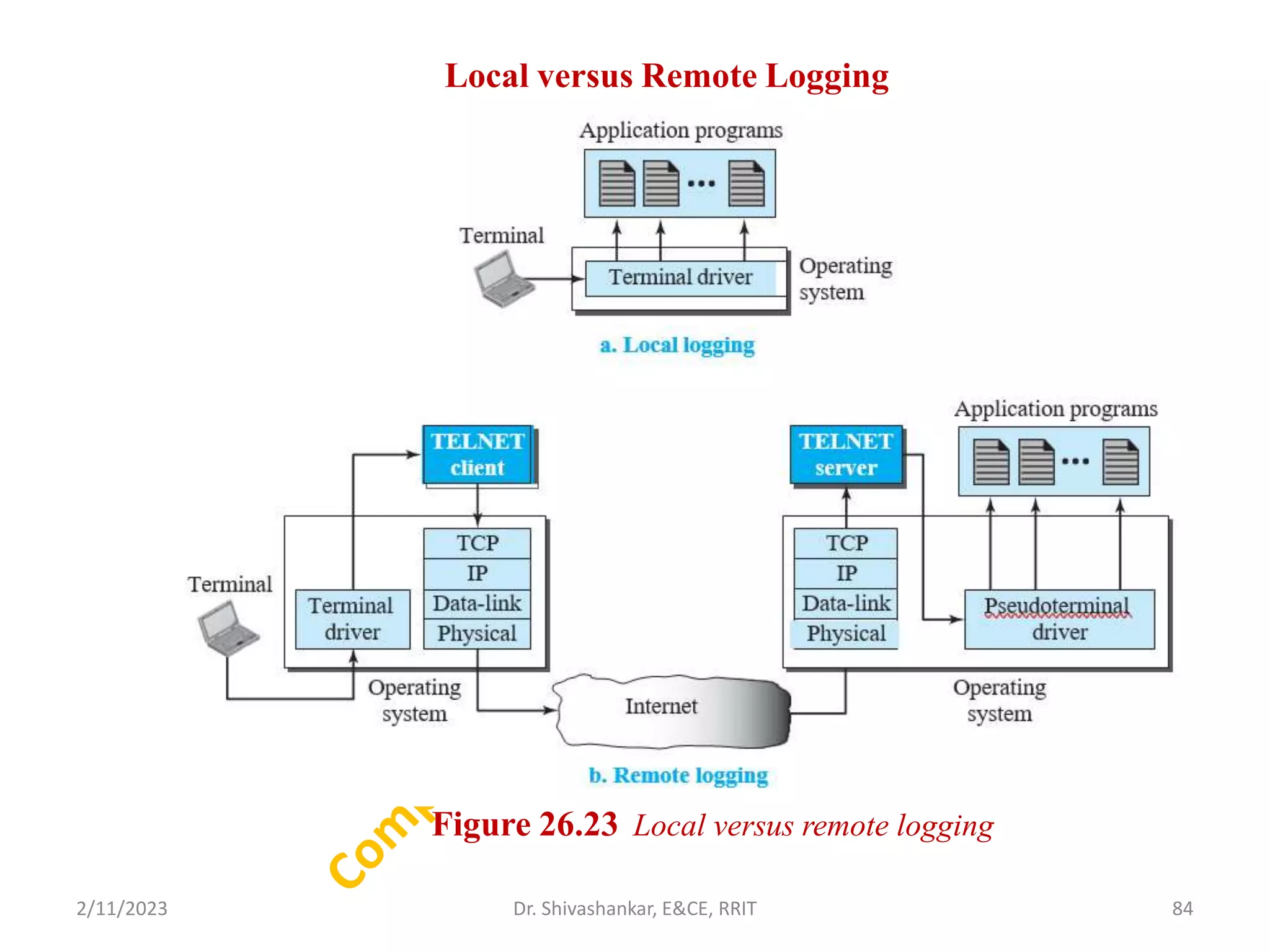
Local versus RemoteLogging
2/11/2023 84
Dr. Shivashankar, E&CE, RRIT
Figure 26.23 Local versus remote logging
85.
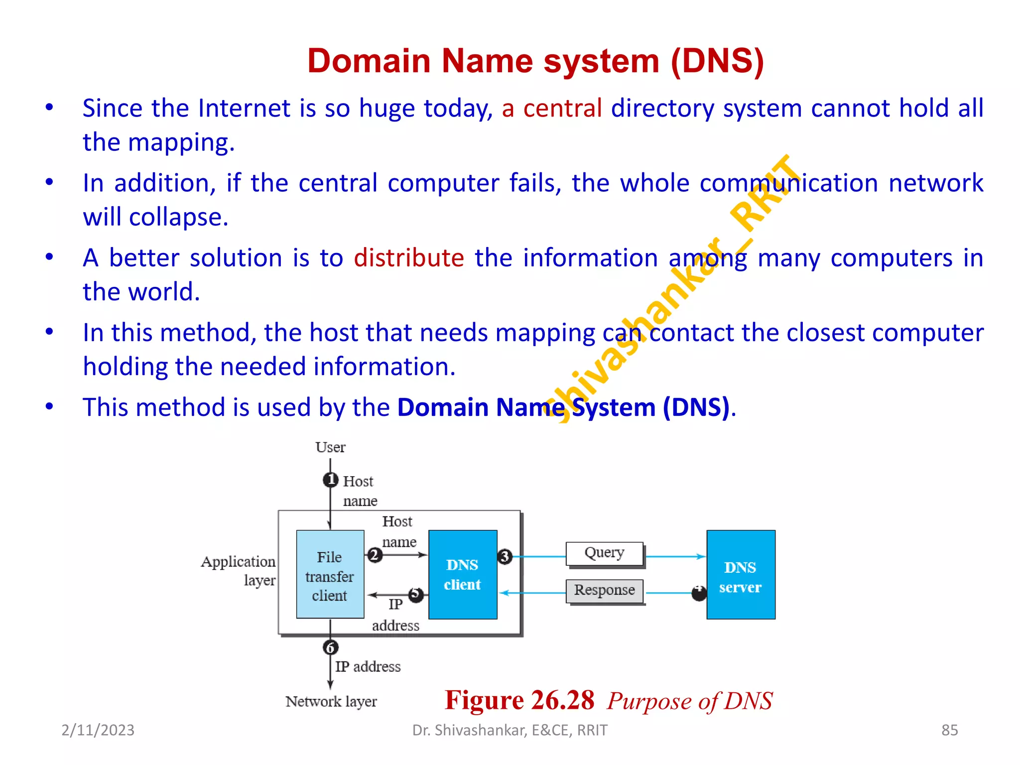
Domain Name system(DNS)
• Since the Internet is so huge today, a central directory system cannot hold all
the mapping.
• In addition, if the central computer fails, the whole communication network
will collapse.
• A better solution is to distribute the information among many computers in
the world.
• In this method, the host that needs mapping can contact the closest computer
holding the needed information.
• This method is used by the Domain Name System (DNS).
2/11/2023 85
Dr. Shivashankar, E&CE, RRIT
Figure 26.28 Purpose of DNS
86.
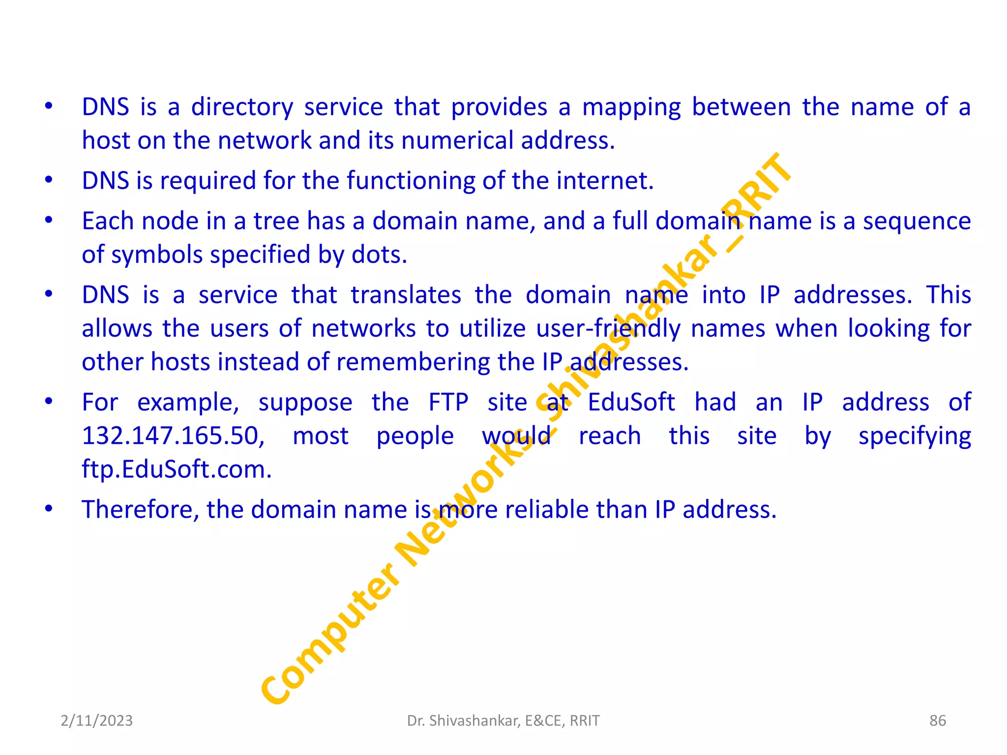
• DNS isa directory service that provides a mapping between the name of a
host on the network and its numerical address.
• DNS is required for the functioning of the internet.
• Each node in a tree has a domain name, and a full domain name is a sequence
of symbols specified by dots.
• DNS is a service that translates the domain name into IP addresses. This
allows the users of networks to utilize user-friendly names when looking for
other hosts instead of remembering the IP addresses.
• For example, suppose the FTP site at EduSoft had an IP address of
132.147.165.50, most people would reach this site by specifying
ftp.EduSoft.com.
• Therefore, the domain name is more reliable than IP address.
2/11/2023 86
Dr. Shivashankar, E&CE, RRIT
87.
Name Space
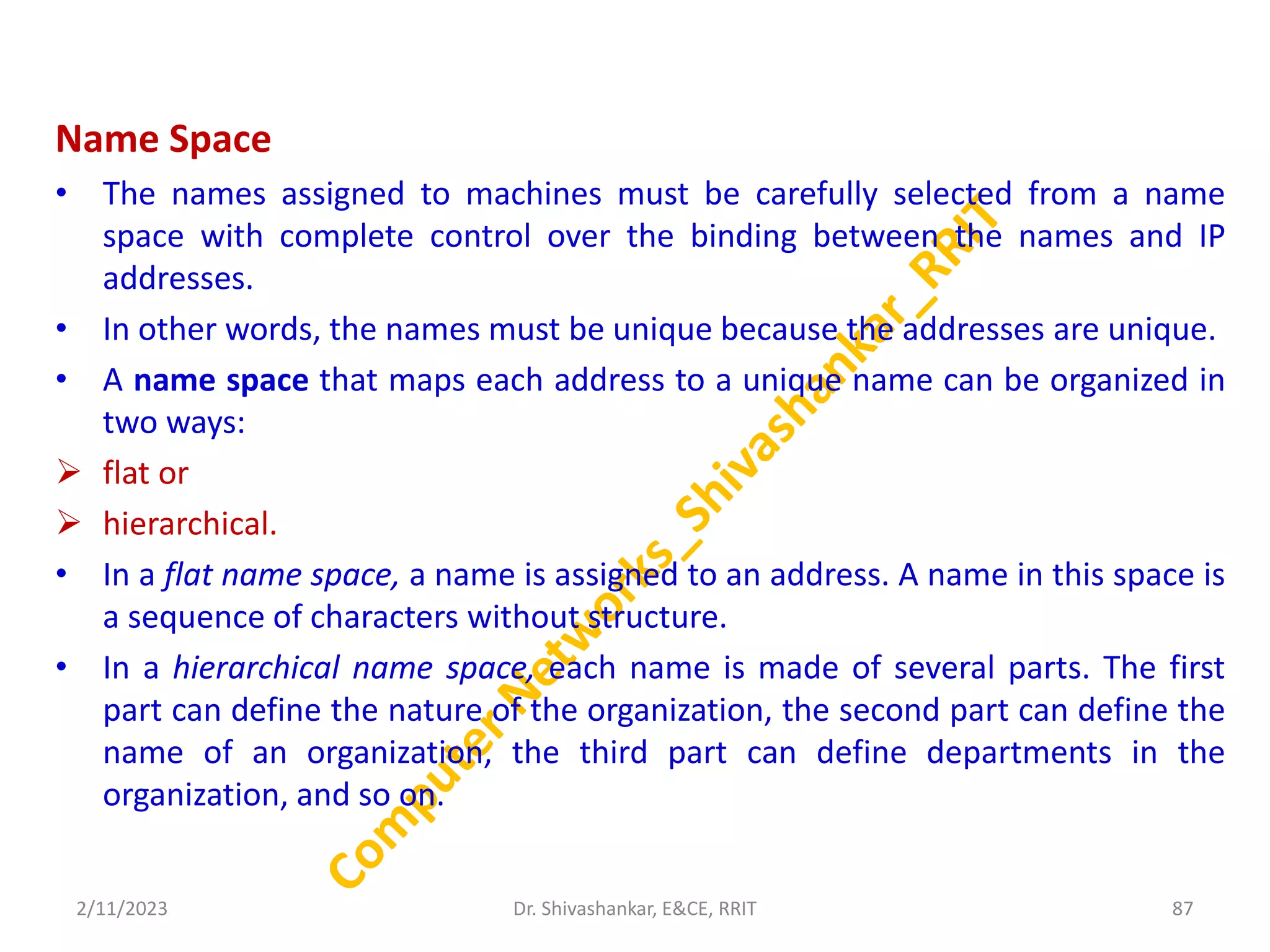
• Thenames assigned to machines must be carefully selected from a name
space with complete control over the binding between the names and IP
addresses.
• In other words, the names must be unique because the addresses are unique.
• A name space that maps each address to a unique name can be organized in
two ways:
flat or
hierarchical.
• In a flat name space, a name is assigned to an address. A name in this space is
a sequence of characters without structure.
• In a hierarchical name space, each name is made of several parts. The first
part can define the nature of the organization, the second part can define the
name of an organization, the third part can define departments in the
organization, and so on.
2/11/2023 87
Dr. Shivashankar, E&CE, RRIT
88.
DNS in theInternet
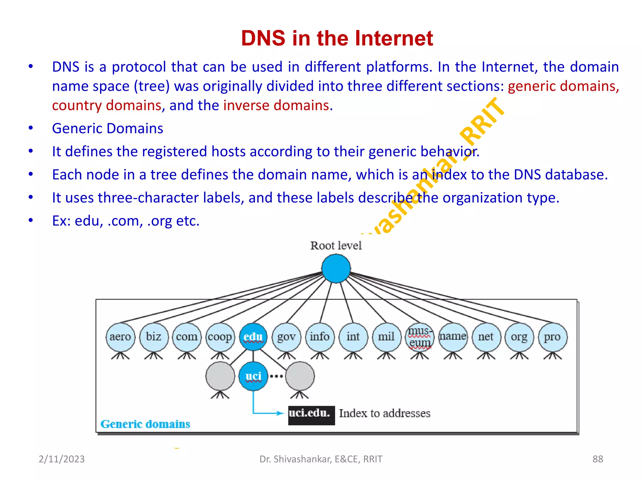
• DNS is a protocol that can be used in different platforms. In the Internet, the domain
name space (tree) was originally divided into three different sections: generic domains,
country domains, and the inverse domains.
• Generic Domains
• It defines the registered hosts according to their generic behavior.
• Each node in a tree defines the domain name, which is an index to the DNS database.
• It uses three-character labels, and these labels describe the organization type.
• Ex: edu, .com, .org etc.
2/11/2023 88
Dr. Shivashankar, E&CE, RRIT
89.
Resolution
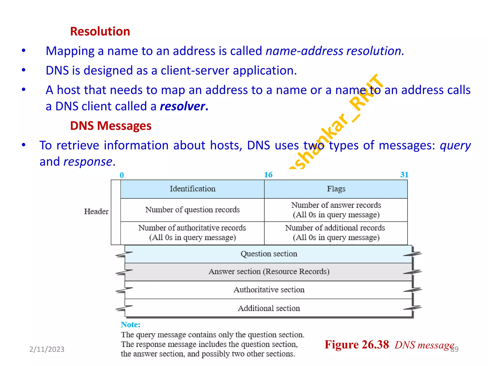
• Mapping aname to an address is called name-address resolution.
• DNS is designed as a client-server application.
• A host that needs to map an address to a name or a name to an address calls
a DNS client called a resolver.
DNS Messages
• To retrieve information about hosts, DNS uses two types of messages: query
and response.
2/11/2023 89
Dr. Shivashankar, E&CE, RRIT Figure 26.38 DNS message
90.
Registrars
• How arenew domains added to DNS? This is done through a registrar, a
commercial entity accredited by ICANN.
• A registrar first verifies that the requested domain name is unique and then
enters it into the DNS database. A fee is charged.
• Today, there are many registrars; their names and addresses can be found at
• http://www.intenic.net
• To register, the organization needs to give the name of its server and the IP
address of the server.
• For example, a new commercial organization named wonderful with a server
named ws and IP address 200.200.200.5 needs to give the following
information to one of the registrars:
• Domain name: ws.wonderful.com IP address: 200.200.200.5
2/11/2023 90
Dr. Shivashankar, E&CE, RRIT
91.
Dynamic Domain NameSystem (DDNS)
• The DNS master file must be updated dynamically. In DDNS, when a binding
between a name and an address is determined, the information is sent,
usually by DHCP.
• To provide security and prevent unauthorized changes in the DNS records,
DDNS can use an authentication mechanism.
Security of DNS
• DNS is one of the most important systems in the Internet infrastructure; it
provides cru- cial services to Internet users.
• Applications such as Web access or e-mail are heavily dependent on the
proper operation of DNS.
• To protect DNS, IETF has devised a technology named DNS Security (DNSSEC)
that provides message origin authentication and message integrity using a
security service called digital signature.
2/11/2023 91
Dr. Shivashankar, E&CE, RRIT
![Distance_Vector_Routing ( )
{
D[myself ] = 0
for (y = 1 to N)
{
if (y is a neighbor)
D[y] = c[myself ][y]
else
D[y] = ∞
}
send vector {D[1], D[2], ,,, D[N]} to all neighbors
{
wait (for a vector Dw from a neighbor w or any change in the link)
for (y = 1 to N)
{
D[y] = min [D[y], (c[myself ][w] + Dw[y ])] // Bellman-Ford equation
}
if (any change in the vector)
send vector {D[1], D[2],,,, D[N]} to all neighbors
}
}
2/11/2023 33
Dr. Shivashankar, E&CE, RRIT](https://image.slidesharecdn.com/module-3ccn-230211071143-990193a5/75/MODULE-3_CCN-pptx-33-2048.jpg)
![Dijkstra’s Algorithm
2/11/2023 36
Dr. Shivashankar, E&CE, RRIT
for (y = 1 to N) // n number of nodes
{
if (y is the root)
D[y] = 0 // D[y] is shortest distance from root to node y
else if (y is a neighbor)
D[y] = c[root][y] // c[x][y] is cost between nodes x and y in LSDB
else
D[y] = ∞
}
Repeat
{
find a node w, with D[w] minimum among all nodes not in the Tree
Tree = Tree U{w}
for (every node x, which is a neighbor of w and not in the Tree)
{
D[x] = min{D[x], (D[w] + c[w][x])}
}
} until (all nodes included in the Tree)
}](https://image.slidesharecdn.com/module-3ccn-230211071143-990193a5/75/MODULE-3_CCN-pptx-36-2048.jpg)


![Distance_Vector_Routing ( )
{
D[myself ] = 0
for (y = 1 to N)
{
if (y is a neighbor)
D[y] = c[myself ][y]
else
D[y] = ∞
}
send vector {D[1], D[2], ,,, D[N]} to all neighbors
{
wait (for a vector Dw from a neighbor w or any change in the link)
for (y = 1 to N)
{
D[y] = min [D[y], (c[myself ][w] + Dw[y ])] // Bellman-Ford equation
}
if (any change in the vector)
send vector {D[1], D[2],,,, D[N]} to all neighbors
}
}
2/11/2023 33
Dr. Shivashankar, E&CE, RRIT](https://crownmelresort.com/image.slidesharecdn.com/module-3ccn-230211071143-990193a5/75/MODULE-3_CCN-pptx-33-2048.jpg)


![Dijkstra’s Algorithm
2/11/2023 36
Dr. Shivashankar, E&CE, RRIT
for (y = 1 to N) // n number of nodes
{
if (y is the root)
D[y] = 0 // D[y] is shortest distance from root to node y
else if (y is a neighbor)
D[y] = c[root][y] // c[x][y] is cost between nodes x and y in LSDB
else
D[y] = ∞
}
Repeat
{
find a node w, with D[w] minimum among all nodes not in the Tree
Tree = Tree U{w}
for (every node x, which is a neighbor of w and not in the Tree)
{
D[x] = min{D[x], (D[w] + c[w][x])}
}
} until (all nodes included in the Tree)
}](https://crownmelresort.com/image.slidesharecdn.com/module-3ccn-230211071143-990193a5/75/MODULE-3_CCN-pptx-36-2048.jpg)