What is BehavioralModeling
Describes behavior of the circuit
Represents circuit at high level of
abstraction
3.
Structured Procedures
Always
Initial
All behavioral statements appear inside
these structured procedure statements
Can not be nested
4.
Initial
Execute exactlyonce during simulation at
time 0
Multiple initial blocks starts to execute
concurrently at time 0
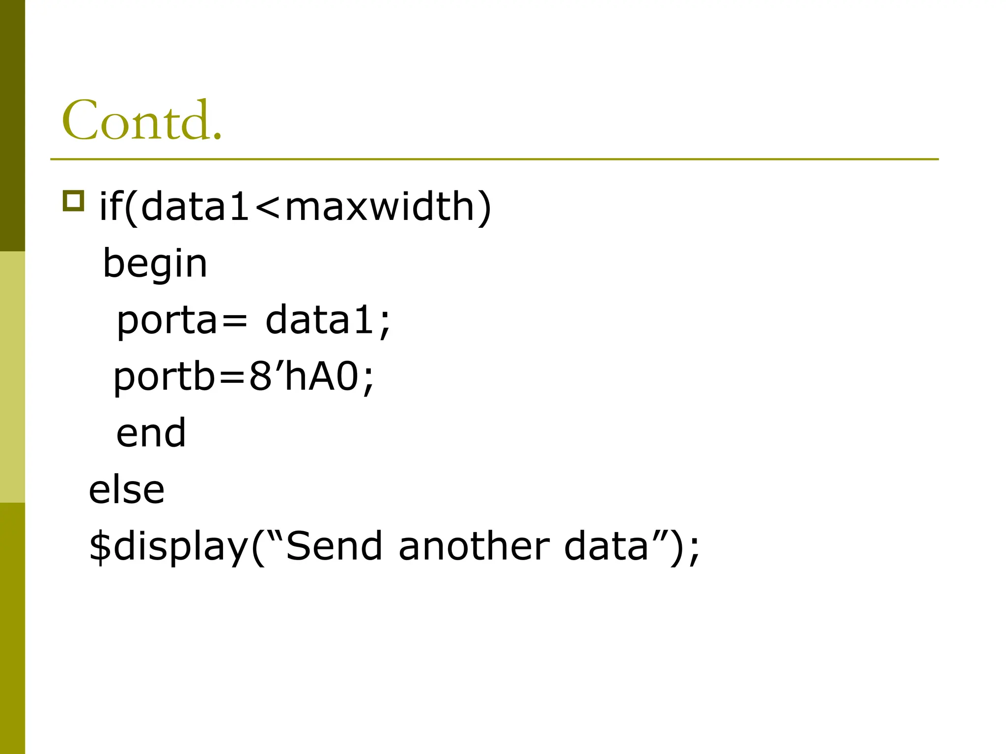
Multiple statements must be grouped
inside begin and end keyword
For single statement need not ne enclosed
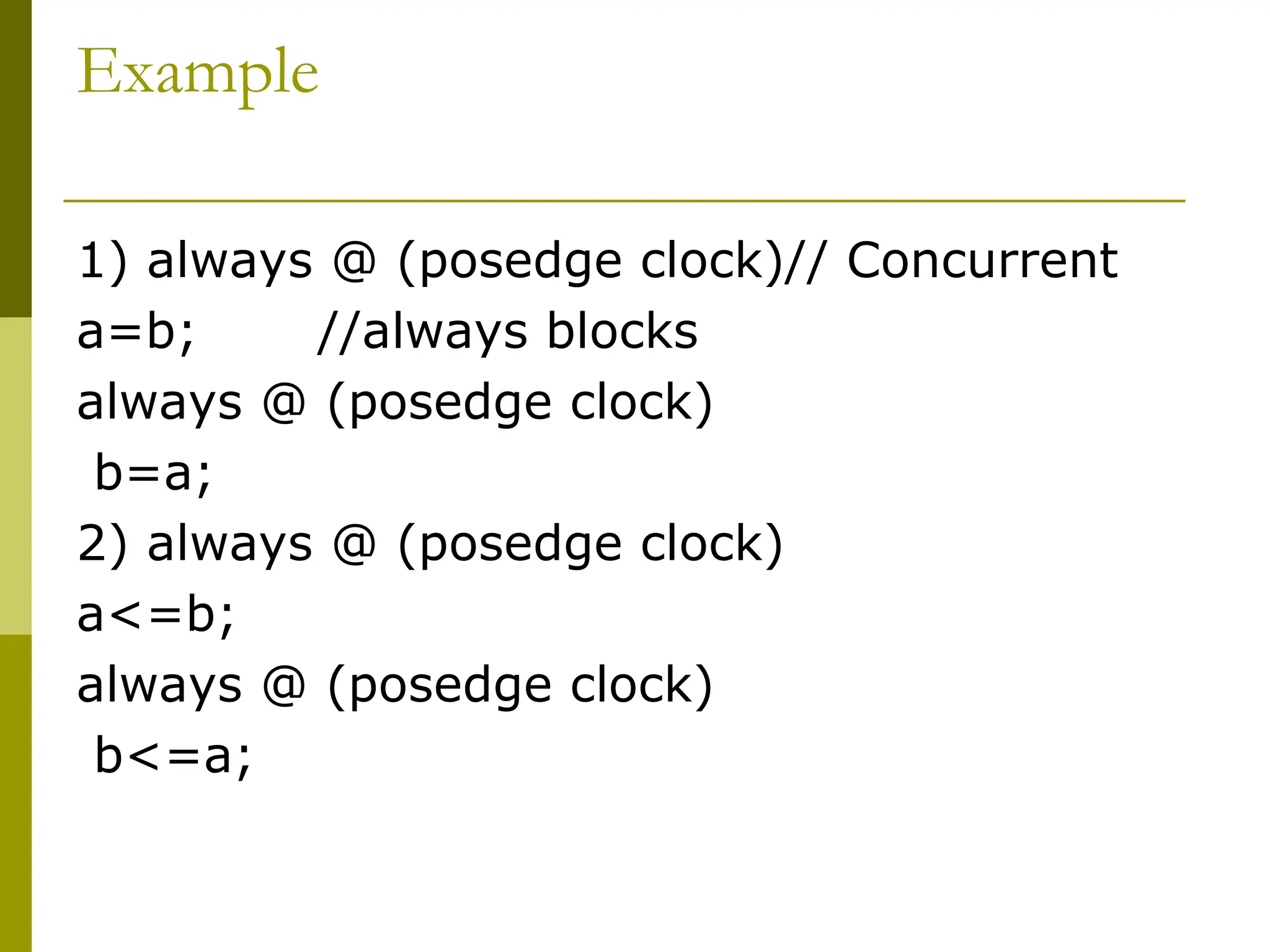
Example
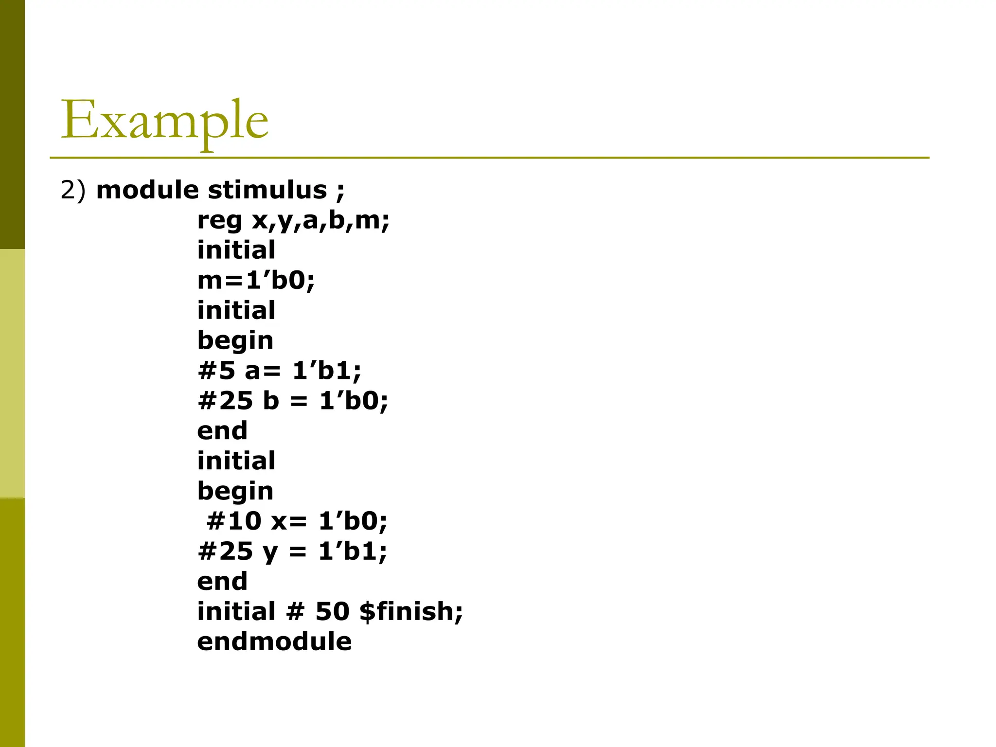
2) module stimulus;
reg x,y,a,b,m;
initial
m=1’b0;
initial
begin
#5 a= 1’b1;
#25 b = 1’b0;
end
initial
begin
#10 x= 1’b0;
#25 y = 1’b1;
end
initial # 50 $finish;
endmodule
11.
Execution
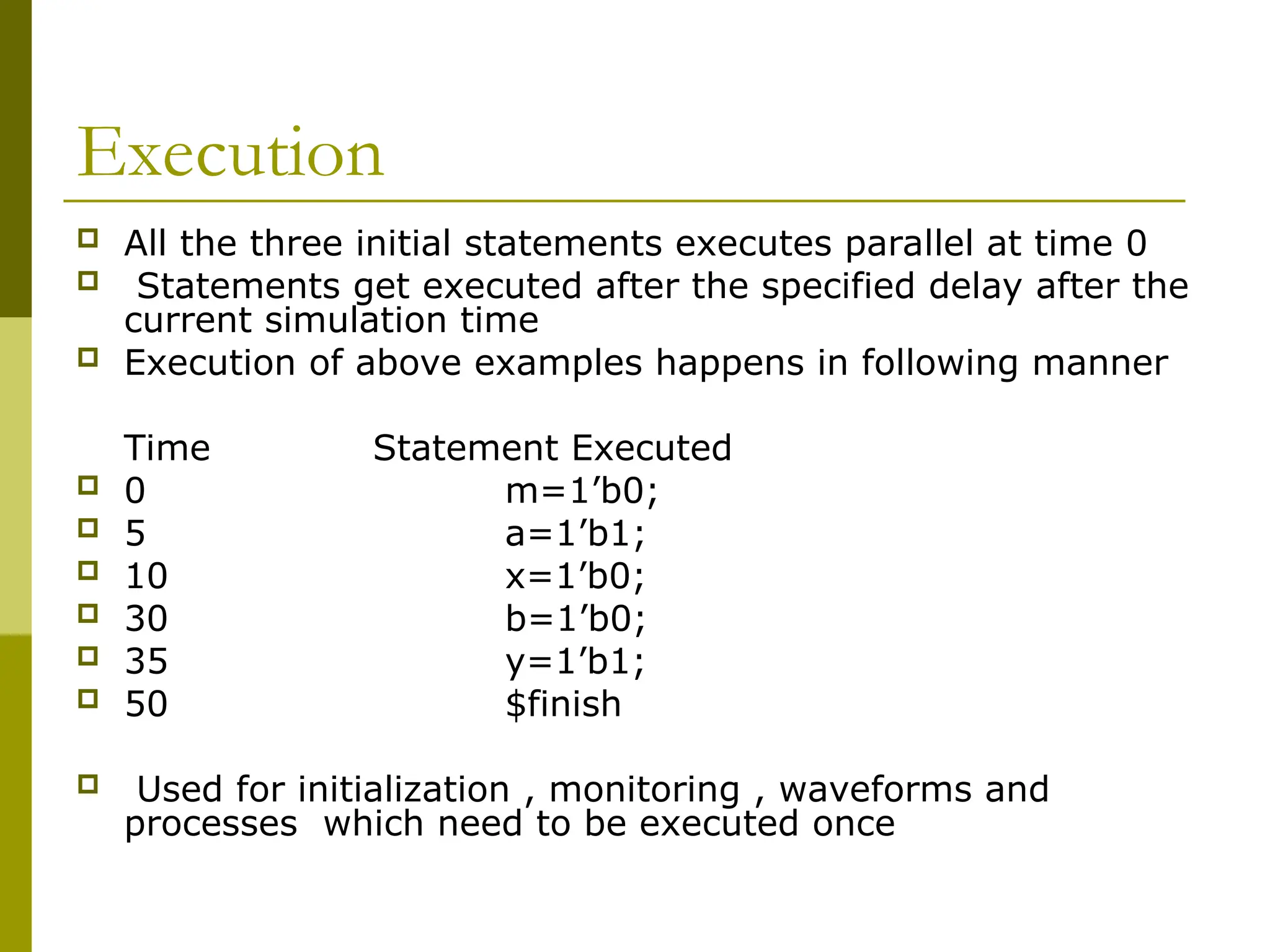
All thethree initial statements executes parallel at time 0
Statements get executed after the specified delay after the
current simulation time
Execution of above examples happens in following manner
Time Statement Executed
0 m=1’b0;
5 a=1’b1;
10 x=1’b0;
30 b=1’b0;
35 y=1’b1;
50 $finish
Used for initialization , monitoring , waveforms and
processes which need to be executed once
12.
Declarartion and Initialization
Combined variable declarartion and initialization
ex.
Reg clock;
initial clock =0;
or
reg clock =0; // allowed only for variables which are declared at the
module
// level
Combined Port declaration and initialization
ex. module rca (sum,cout,a,b,cin);
output reg [3:0] sum =0;//initialize 4 bit output sum
output reg cout = 0;
input [3:0] a,b;
input cin;
.
.
endmodule
13.
Always
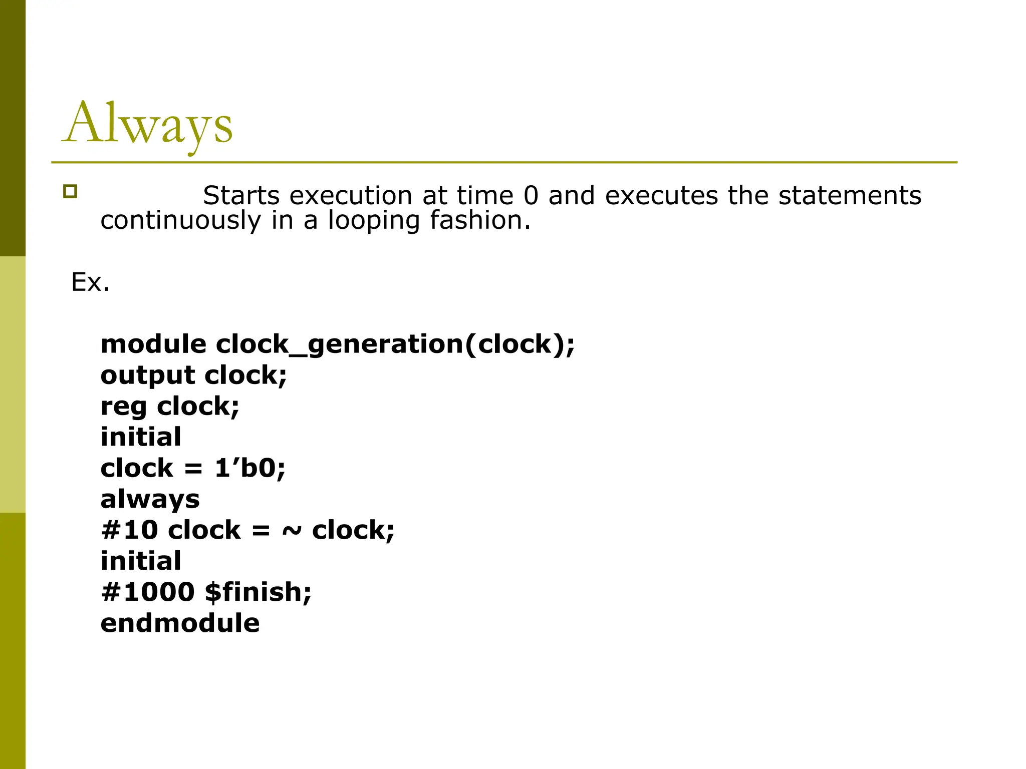
Starts executionat time 0 and executes the statements
continuously in a looping fashion.
Ex.
module clock_generation(clock);
output clock;
reg clock;
initial
clock = 1’b0;
always
#10 clock = ~ clock;
initial
#1000 $finish;
endmodule
14.
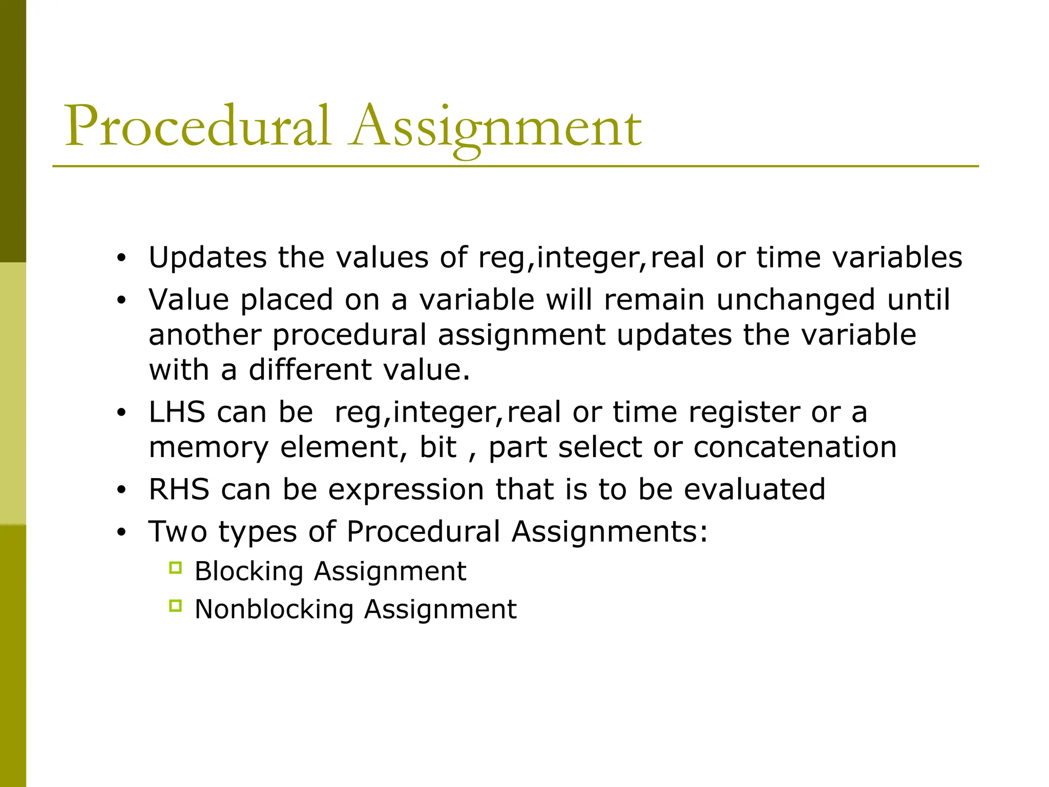
Procedural Assignment
• Updatesthe values of reg,integer,real or time variables
• Value placed on a variable will remain unchanged until
another procedural assignment updates the variable
with a different value.
• LHS can be reg,integer,real or time register or a
memory element, bit , part select or concatenation
• RHS can be expression that is to be evaluated
• Two types of Procedural Assignments:
Blocking Assignment
Nonblocking Assignment
15.
Blocking Assignments
• Executedin the order they are specified in a sequential block
• Will not block execution of statements that follow in a parallal block.
• = is used to specify blocking statement
Ex.
reg x,y,z;
reg [15:0] rega,regb;
integer count;
initial
begin
X=0;
Y=1;
Z=1;
Count=0;
rega = 16’b0;
Regb=rega;
#15 rega[2]= 1’b1;
#10 regb[15:13] = {x,y,z}
Count = count +1;
end
16.
Execution
Y=1 getsexecuted only after x=0 is
executed
Sequential execution if blocking
statements are used
Simulation for the execution
X=0 to regb=rega are executed at time 0
Rega[2] = 1 at time 15
regb[15:13] = {x,y,z} at time 25
count=count +1 at time 25
17.
Non Blocking Assignments
Allows scheduling of assignments without blocking
execution of the statements that follow in a
sequential block
<= is used for assignments
18.
Example
reg x,y,z;
reg [15:0]rega,regb;
integer count;
initial
begin
X=0;
Y=1;
Z=1;
count=0;
rega = 16’b0;
regb=rega;
rega[2] <= #15 1’b1;
regb[15:13] <= #10 {x,y,z}
count< = count +1;
end
19.
Execution
X=0 toregb=rega are executed sequentially at
time 0
Rega[2]= 1 is scheduled to execute after 15
units
Regb[15:13] = {x,y,z} is scheduled to execute
after 10 time units
Count = count +1 is scheduled to be executed
without any delay at time 0
Do not mix blocking and non blocking
assignment in the same always block
Used to model several concurrent data transfer
that take place after a common event.
20.
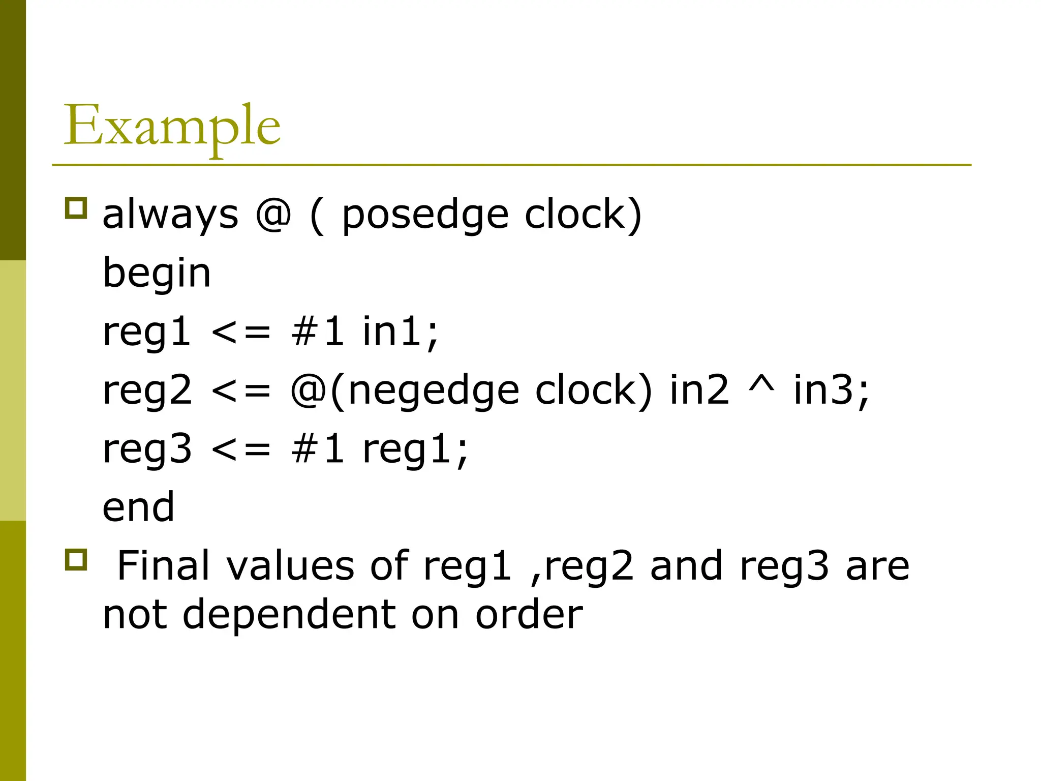
Example
always @( posedge clock)
begin
reg1 <= #1 in1;
reg2 <= @(negedge clock) in2 ^ in3;
reg3 <= #1 reg1;
end
Final values of reg1 ,reg2 and reg3 are
not dependent on order
21.
Execution
At everypositive edge ,the values of the
input variables are read and RHS are
evaluated and results are stored internally
in the simulator.
LHS gets the value after the specified intra
assignment delay
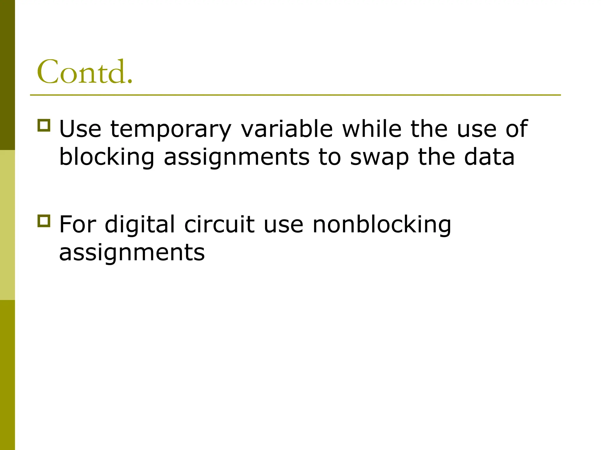
Contd.
Use temporaryvariable while the use of
blocking assignments to swap the data
For digital circuit use nonblocking
assignments
24.
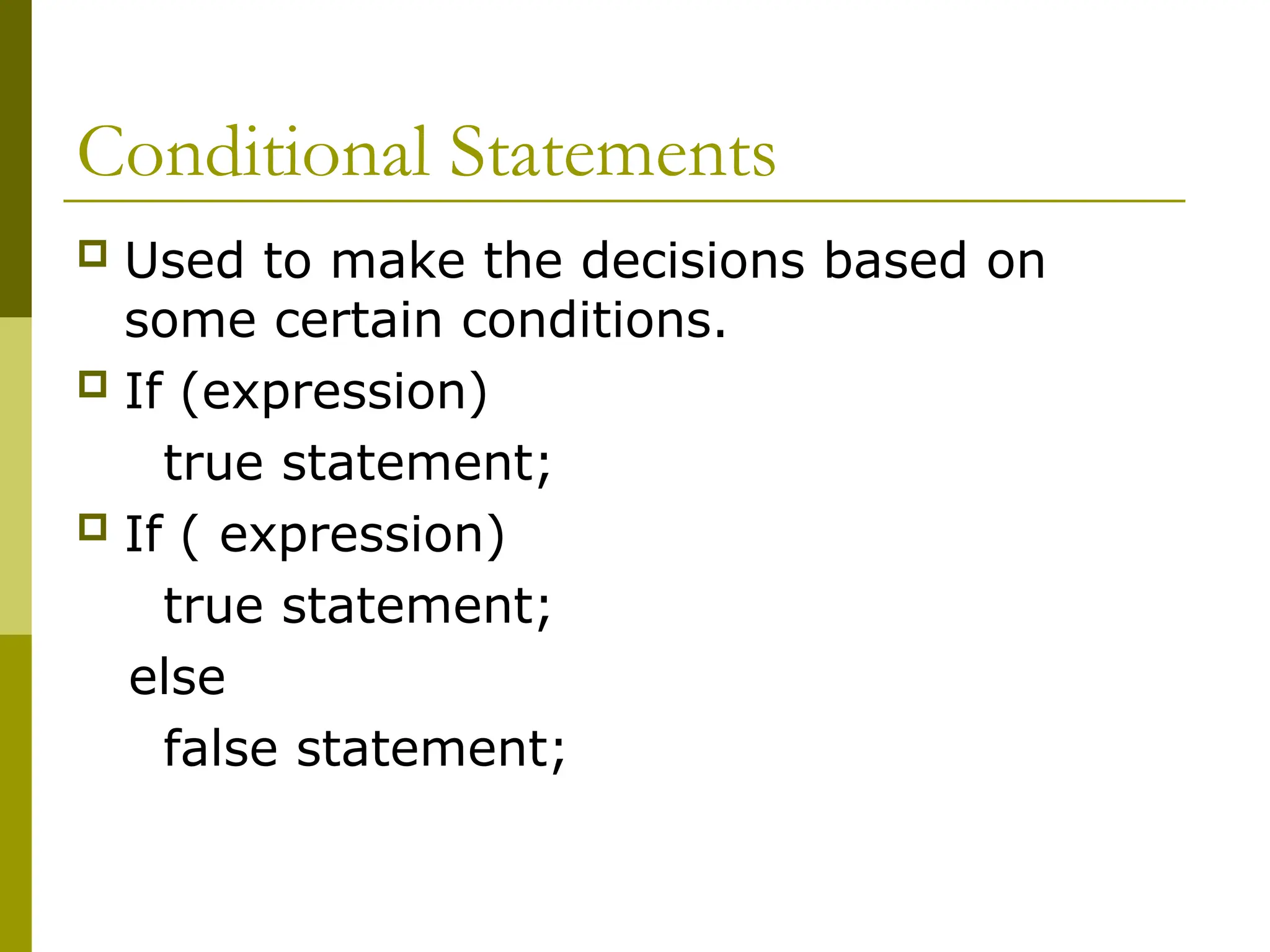
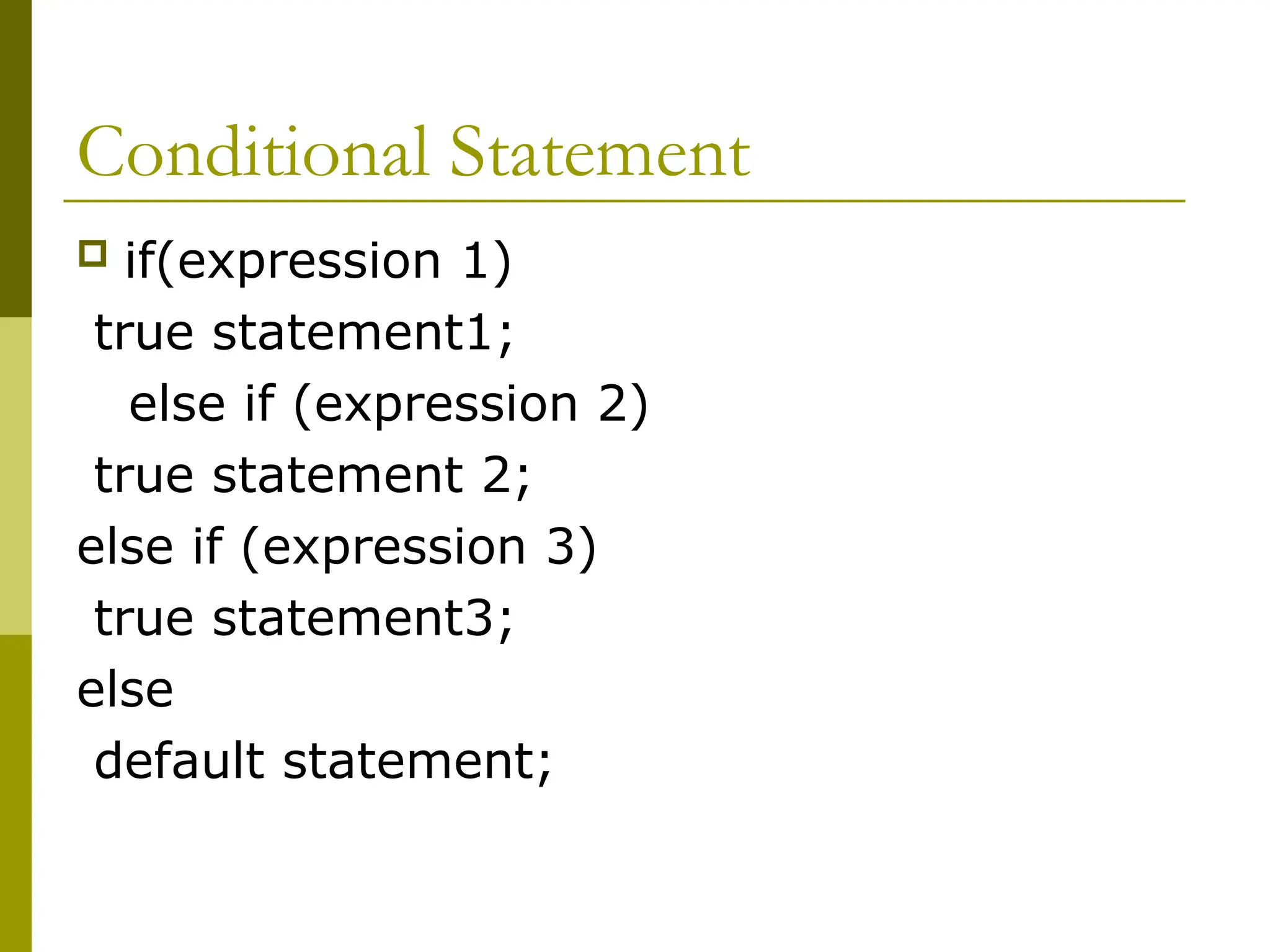
Conditional Statements
Usedto make the decisions based on
some certain conditions.
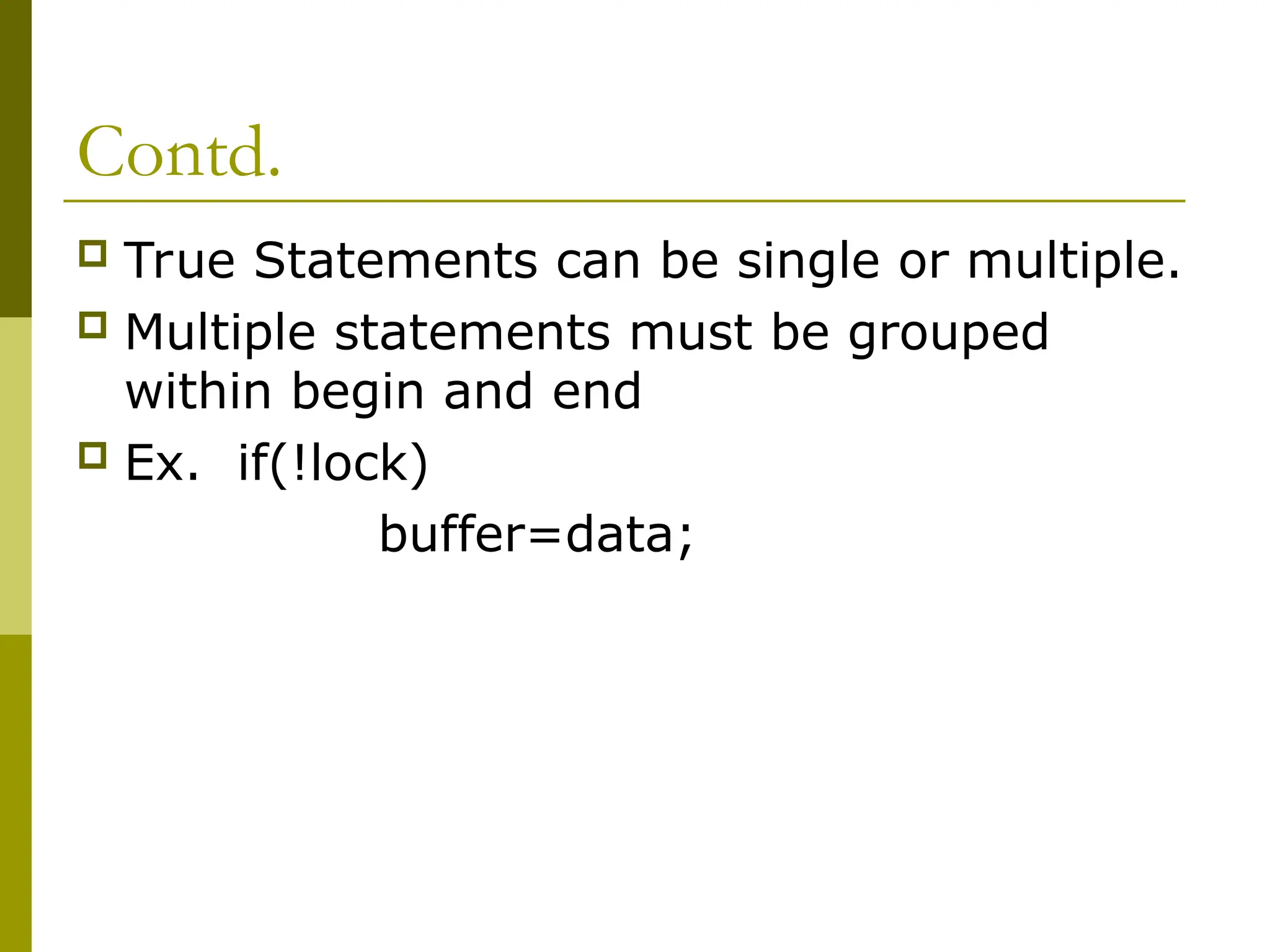
If (expression)
true statement;
If ( expression)
true statement;
else
false statement;
Contd.
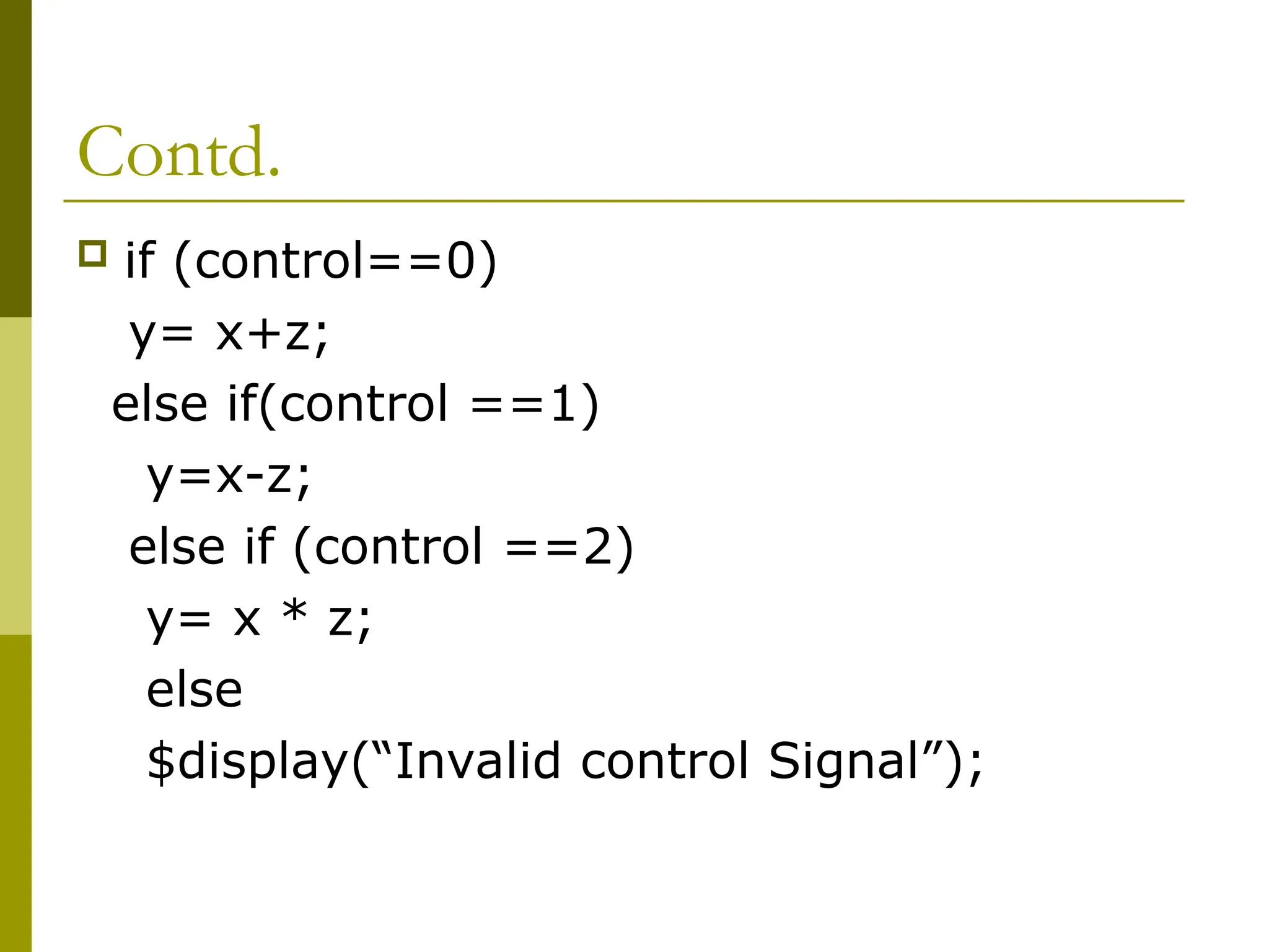
if (control==0)
y=x+z;
else if(control ==1)
y=x-z;
else if (control ==2)
y= x * z;
else
$display(“Invalid control Signal”);
29.
Class Work
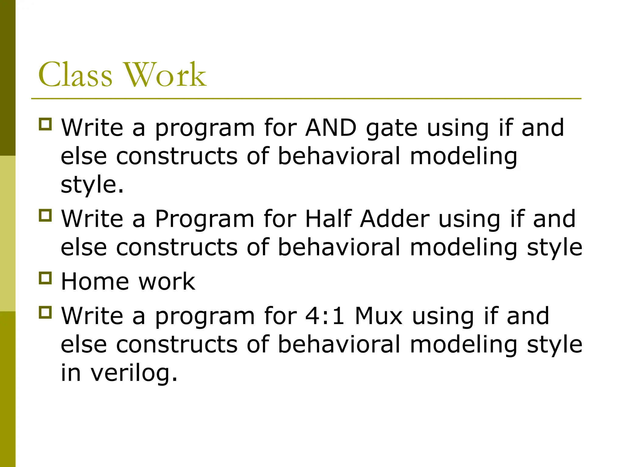
Writea program for AND gate using if and
else constructs of behavioral modeling
style.
Write a Program for Half Adder using if and
else constructs of behavioral modeling style
Home work
Write a program for 4:1 Mux using if and
else constructs of behavioral modeling style
in verilog.
30.
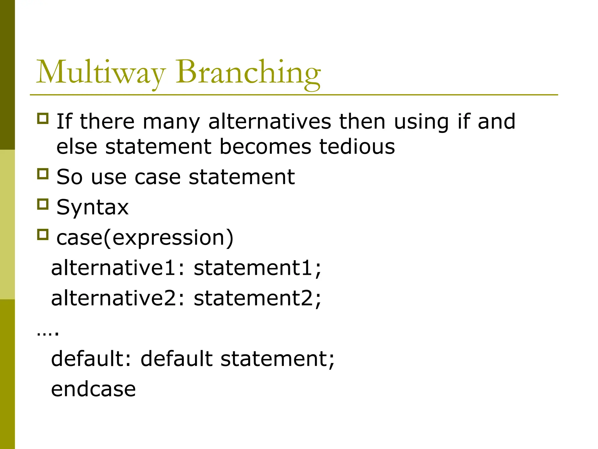
Multiway Branching
Ifthere many alternatives then using if and
else statement becomes tedious
So use case statement
Syntax
case(expression)
alternative1: statement1;
alternative2: statement2;
….
default: default statement;
endcase
31.
Contd.
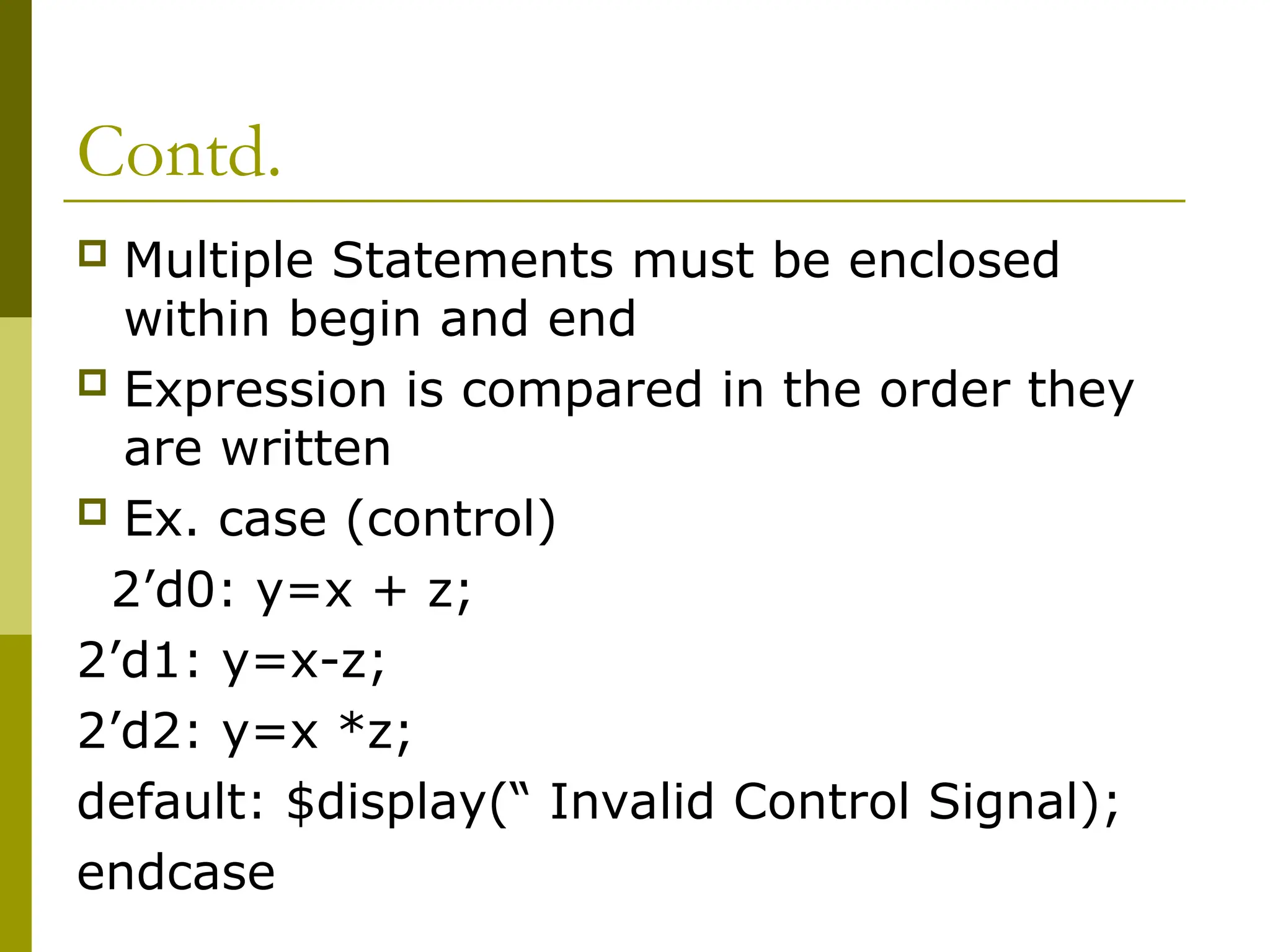
Multiple Statementsmust be enclosed
within begin and end
Expression is compared in the order they
are written
Ex. case (control)
2’d0: y=x + z;
2’d1: y=x-z;
2’d2: y=x *z;
default: $display(“ Invalid Control Signal);
endcase
32.
Contd.
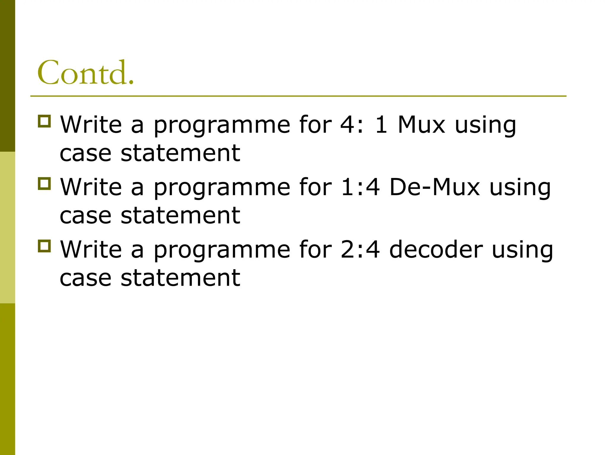
Write aprogramme for 4: 1 Mux using
case statement
Write a programme for 1:4 De-Mux using
case statement
Write a programme for 2:4 decoder using
case statement
33.
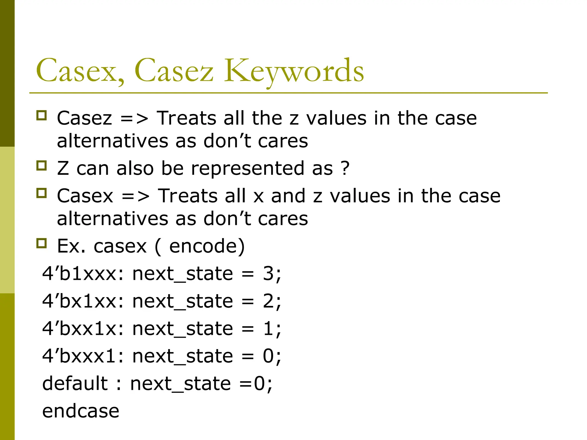
Casex, Casez Keywords
Casez => Treats all the z values in the case
alternatives as don’t cares
Z can also be represented as ?
Casex => Treats all x and z values in the case
alternatives as don’t cares
Ex. casex ( encode)
4’b1xxx: next_state = 3;
4’bx1xx: next_state = 2;
4’bxx1x: next_state = 1;
4’bxxx1: next_state = 0;
default : next_state =0;
endcase
34.
Loops
while
for
repeat
forever
Looping statements can appear only inside
initial or always block
May contain delay expressions
35.
While Loop
Keyword– while
Loop executes until the expression is not
true
Ex.
36.
Example
A increasingsequence of values on an output
reg [3:0] i, out1;
initial
begin
i = 0;
while (i <= 15)
begin
out1 = i;
#10 i = i + 1;
end
end
37.
For Loop
Keyword– for
Contains three part
i) initial condition
ii) condition
iii) procedural assignment to change the
value of the control variable.
38.
Example
A increasingsequence of values on an output
reg [3:0] i, out1;
initial
begin
for ( i = 0 ; i <= 15 ; i = i + 1 )
begin
out1 = i;
$display(“out1= %d”,out1);
#10;
end
end
39.
Example
‘define my_states 15
integerstate[0:’my_states-1];
integer i;
initial
begin
for(i=0;i<15;i=i+2)
state[i]=0;
for(i=1; i<15;i=i+2)
state[i]=1;
end
40.
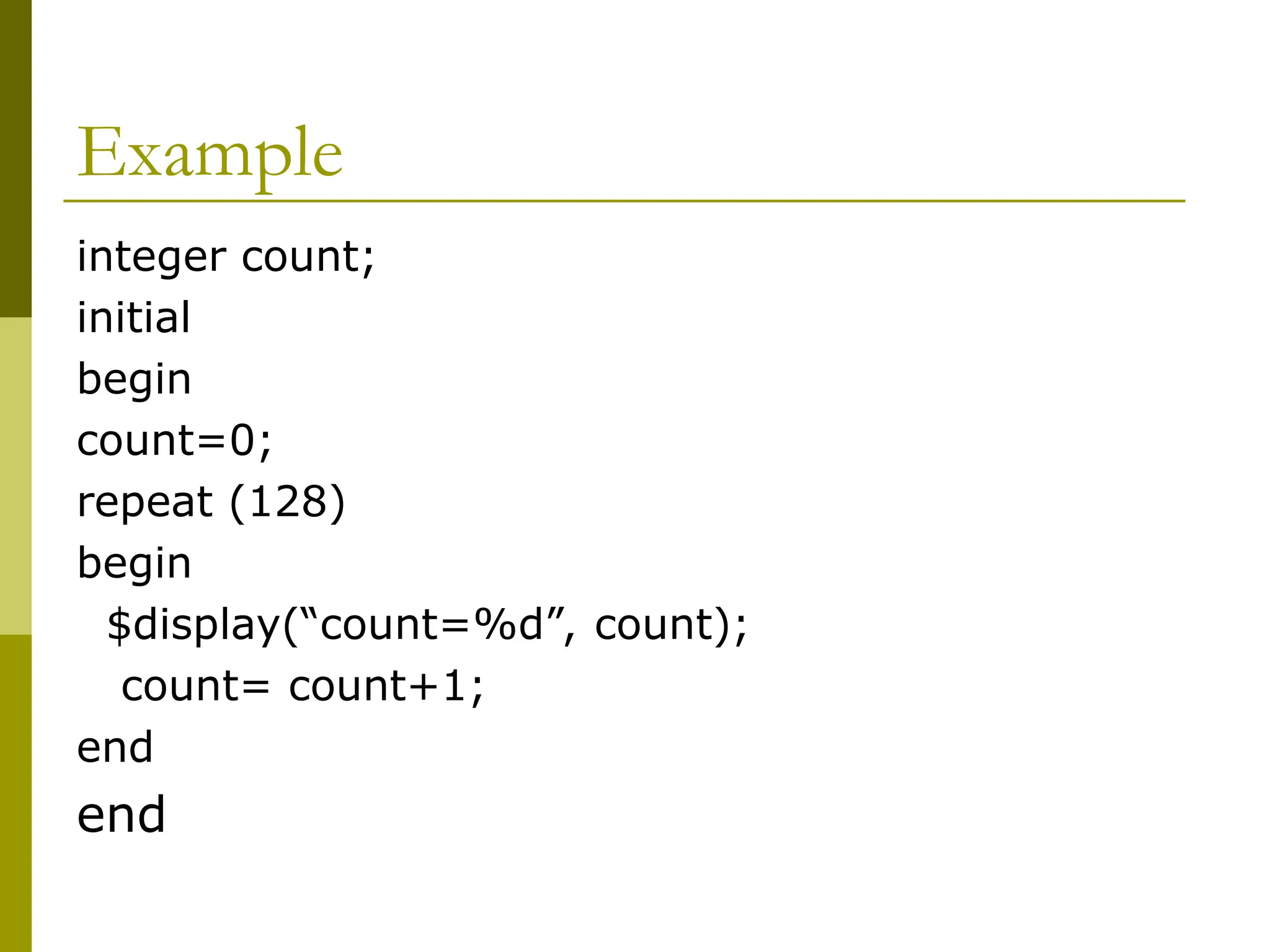
Repeat Loop
Keyword-repeat
Executes the loop for a fixed number of
times
Can not be used to loop on a general
logical expression.
Must contain a constant number or a
variable or a signal value
Evaluated only when the loop starts and
not during the loop execution
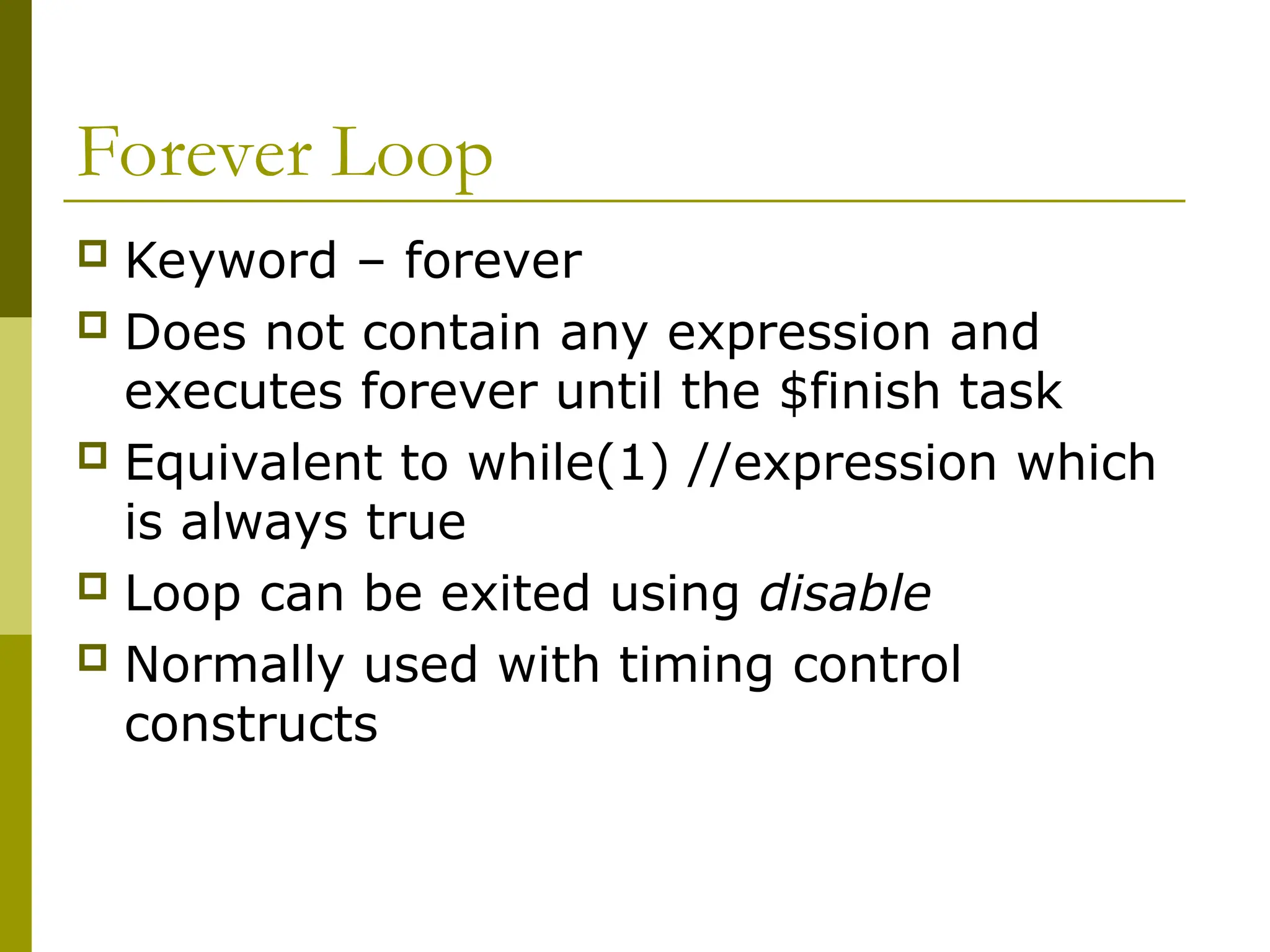
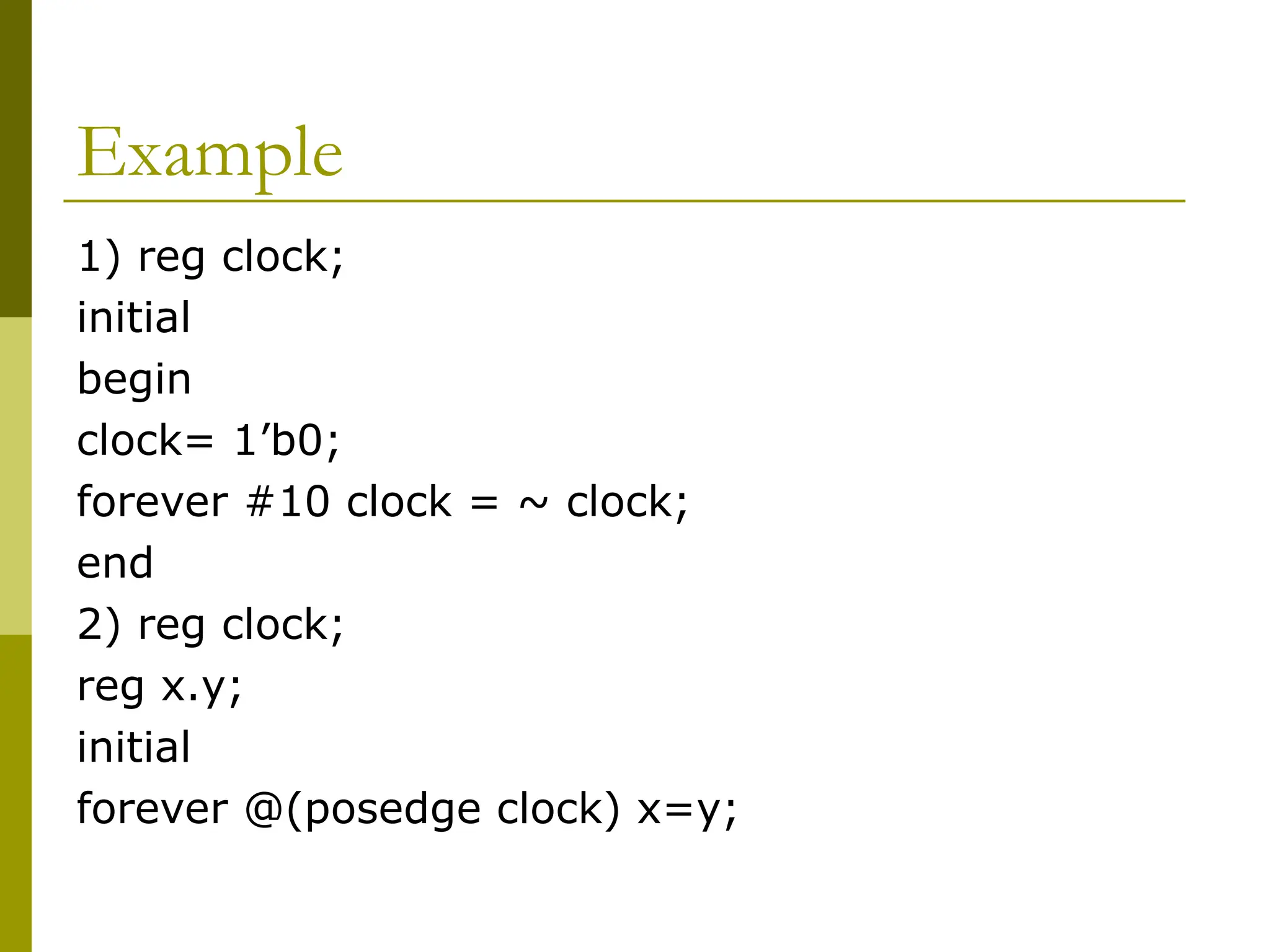
Forever Loop
Keyword– forever
Does not contain any expression and
executes forever until the $finish task
Equivalent to while(1) //expression which
is always true
Loop can be exited using disable
Normally used with timing control
constructs
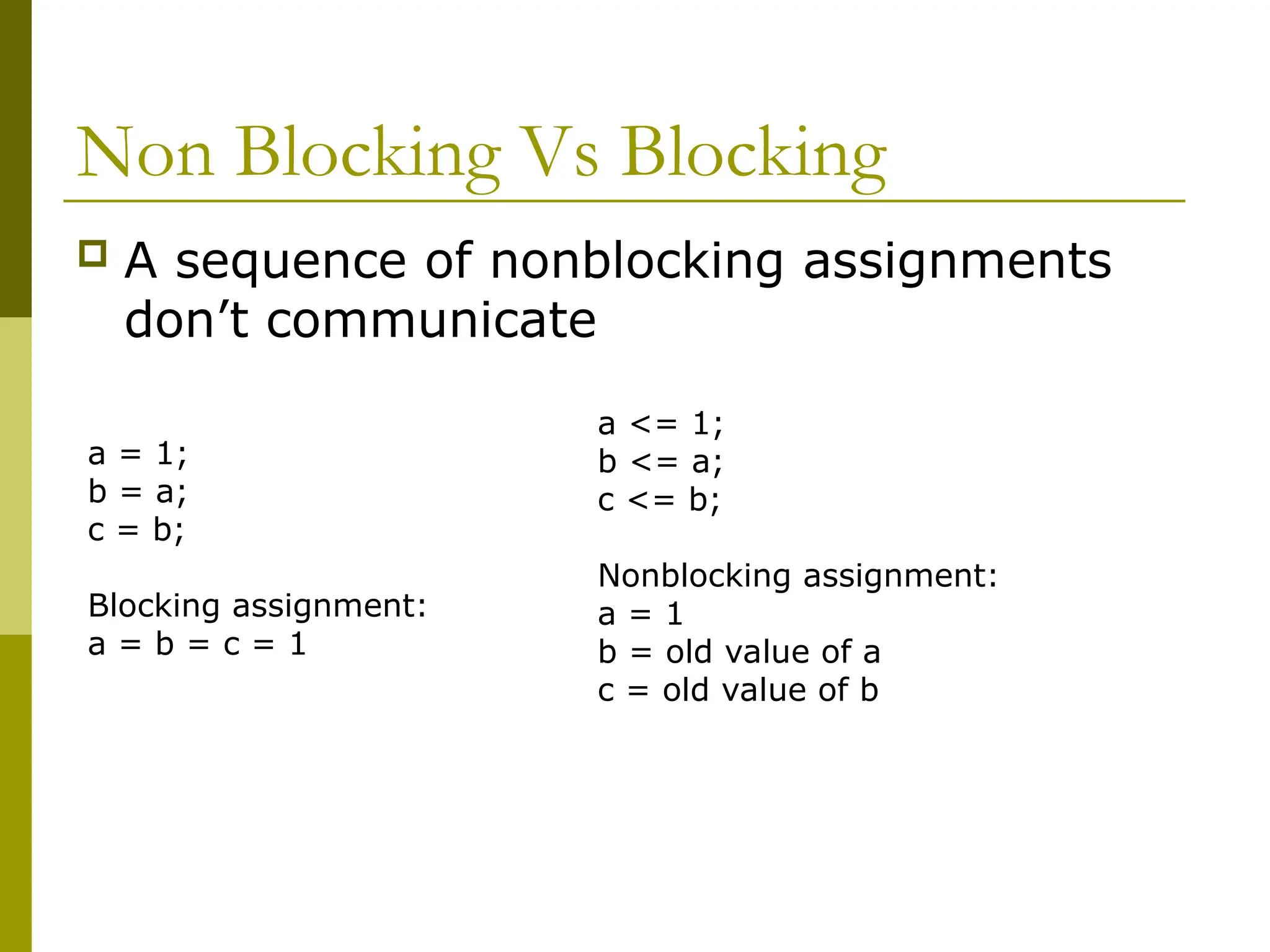
Non Blocking VsBlocking
A sequence of nonblocking assignments
don’t communicate
a = 1;
b = a;
c = b;
Blocking assignment:
a = b = c = 1
a <= 1;
b <= a;
c <= b;
Nonblocking assignment:
a = 1
b = old value of a
c = old value of b
46.
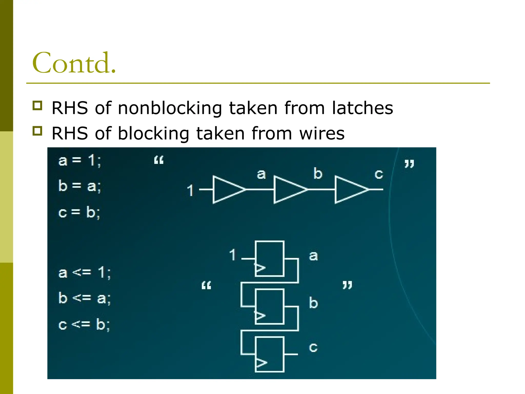
Contd.
RHS ofnonblocking taken from latches
RHS of blocking taken from wires
47.
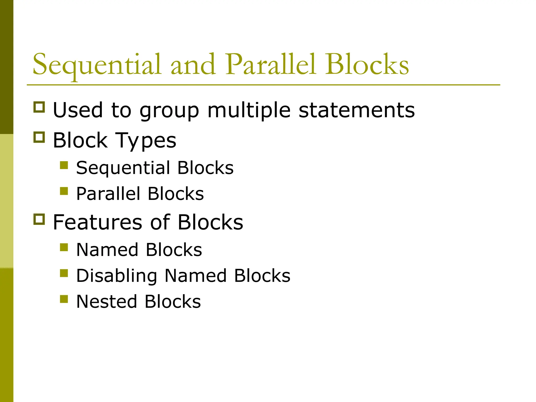
Sequential and ParallelBlocks
Used to group multiple statements
Block Types
Sequential Blocks
Parallel Blocks
Features of Blocks
Named Blocks
Disabling Named Blocks
Nested Blocks
48.
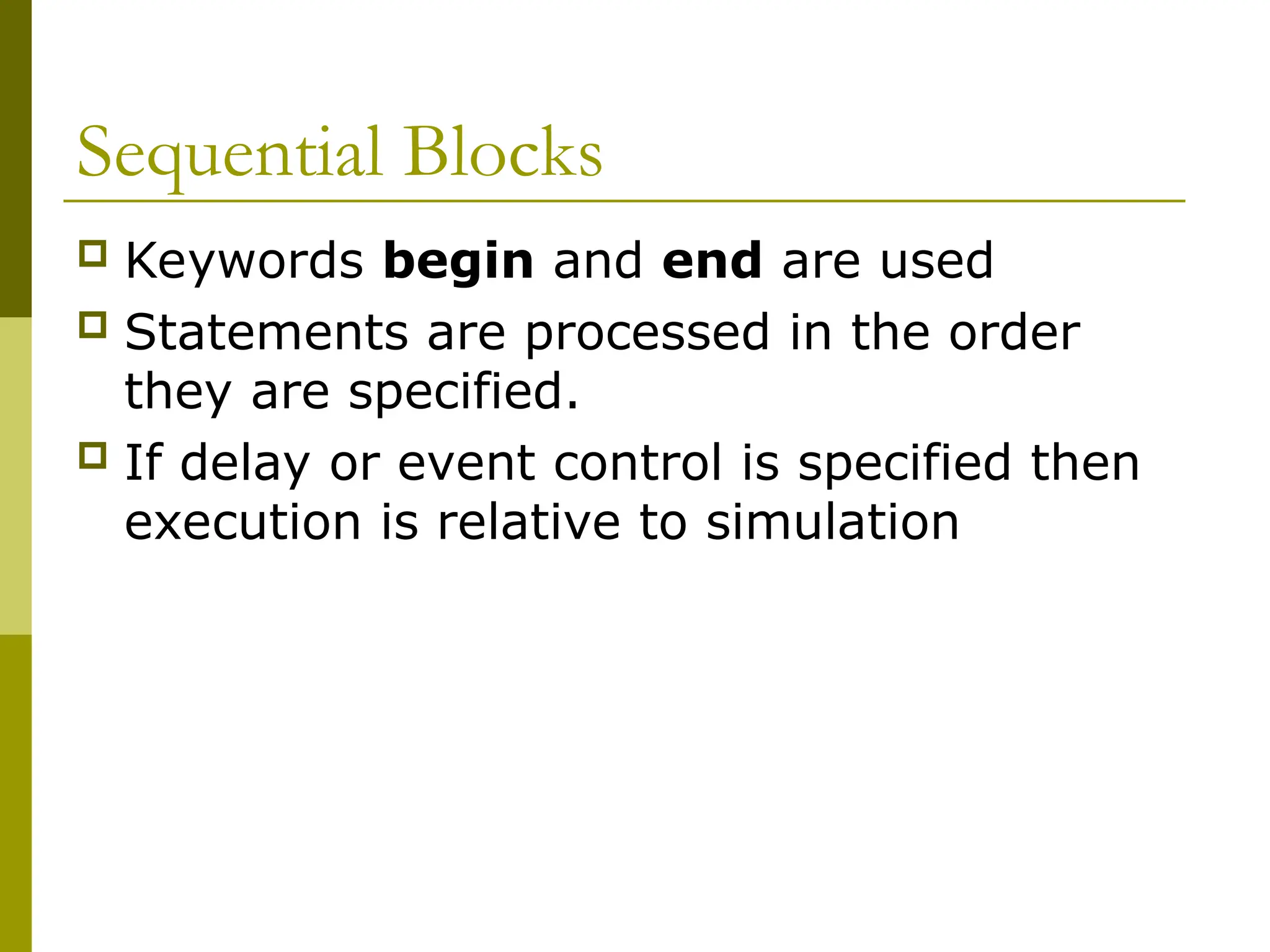
Sequential Blocks
Keywordsbegin and end are used
Statements are processed in the order
they are specified.
If delay or event control is specified then
execution is relative to simulation
49.
Example
reg x,y;
reg [1:0]z,w;
initial
begin
x=1’b0;
y=1’b1;
z= {x,y};
w={y,x};
end
//execution in order at time 0
50.
Example
reg x,y;
reg [1:0]z,w;
initial
begin
x=1’b0; // at time 0
#5 y=1’b1; // at time 5
#10 z= {x,y}; // at time 15
#20 w={y,x}; // at time ?
end
51.
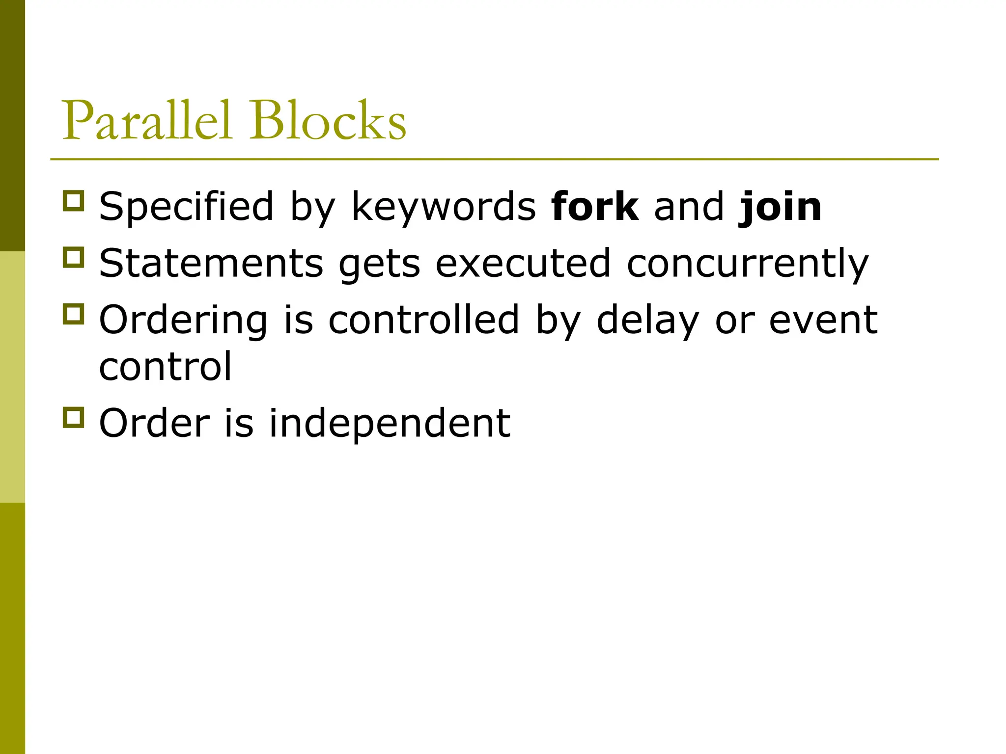
Parallel Blocks
Specifiedby keywords fork and join
Statements gets executed concurrently
Ordering is controlled by delay or event
control
Order is independent
52.
Example
reg x,y;
reg [1:0]z,w;
initial
fork
x=1’b0; // at time 0
#5 y=1’b1; // at time 5
#10 z= {x,y}; //at time 10
#20 w={y,x}; // at time ?
join
// same result except time of simulation
53.
Example – WithRace Condition
reg x,y;
reg [1:0] z,w;
initial
fork
x=1’b0;
y=1’b1;
z= {x,y};
w={y,x};
join
// Execution depends upon Simulation
// implementation
// Limitation of simulators
54.
Special Features ofBlocks
Nested Blocks
reg x,y;
reg [1:0] z,w;
initial
begin
x=1’b0;
fork
#5 y=1’b1;
#10 z= {x,y};
join
#20 w={y,x};
end
55.
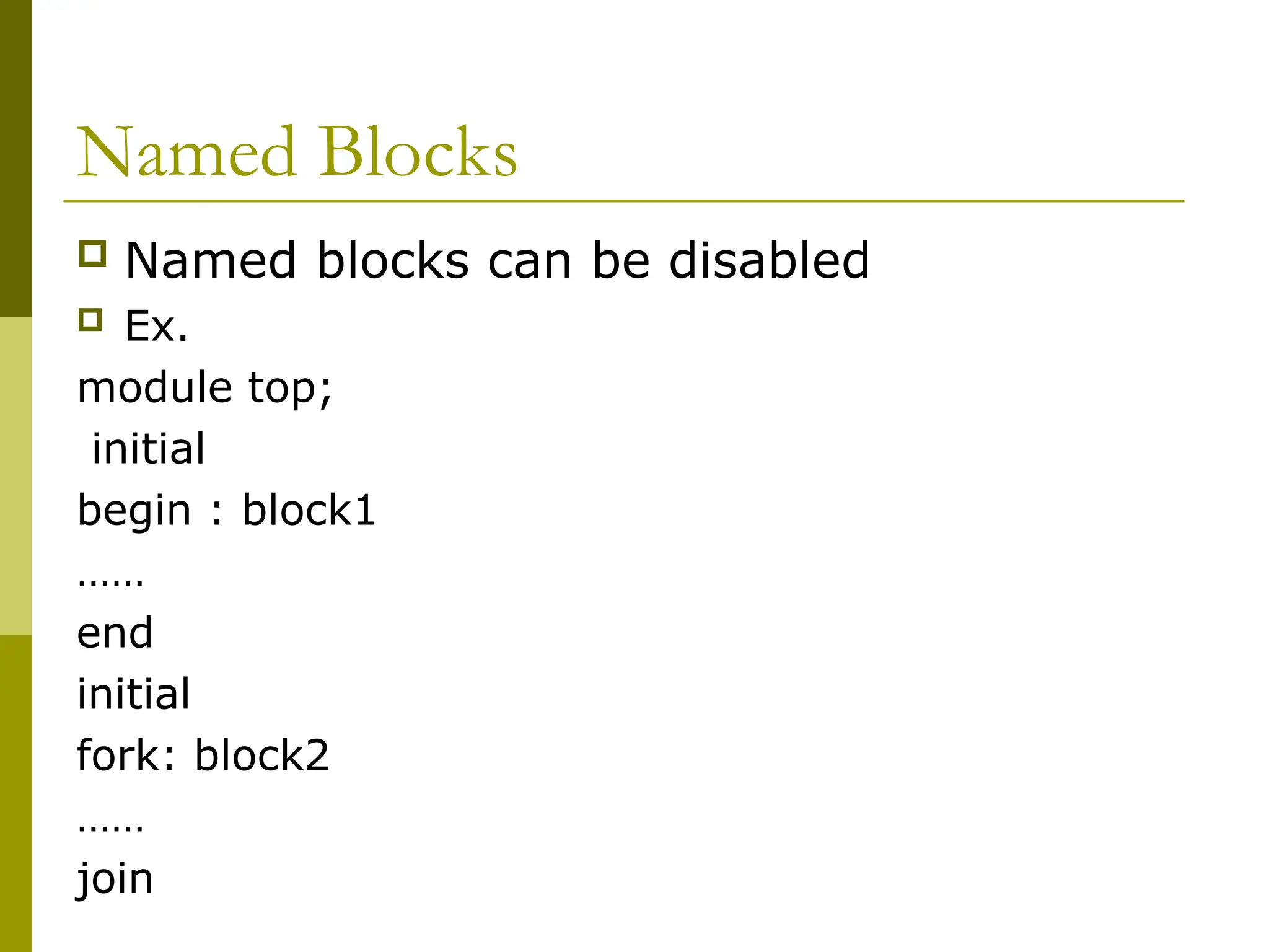
Named Blocks
Namedblocks can be disabled
Ex.
module top;
initial
begin : block1
……
end
initial
fork: block2
……
join
56.
Disabling Named blocks
Keyword disable can be used to get out of
the loops, error conditions etc
initial
begin
porta =8’h08;
i=0;
begin : block1
while (i<8)
begin if (porta[i])
begin
disable block1;
end
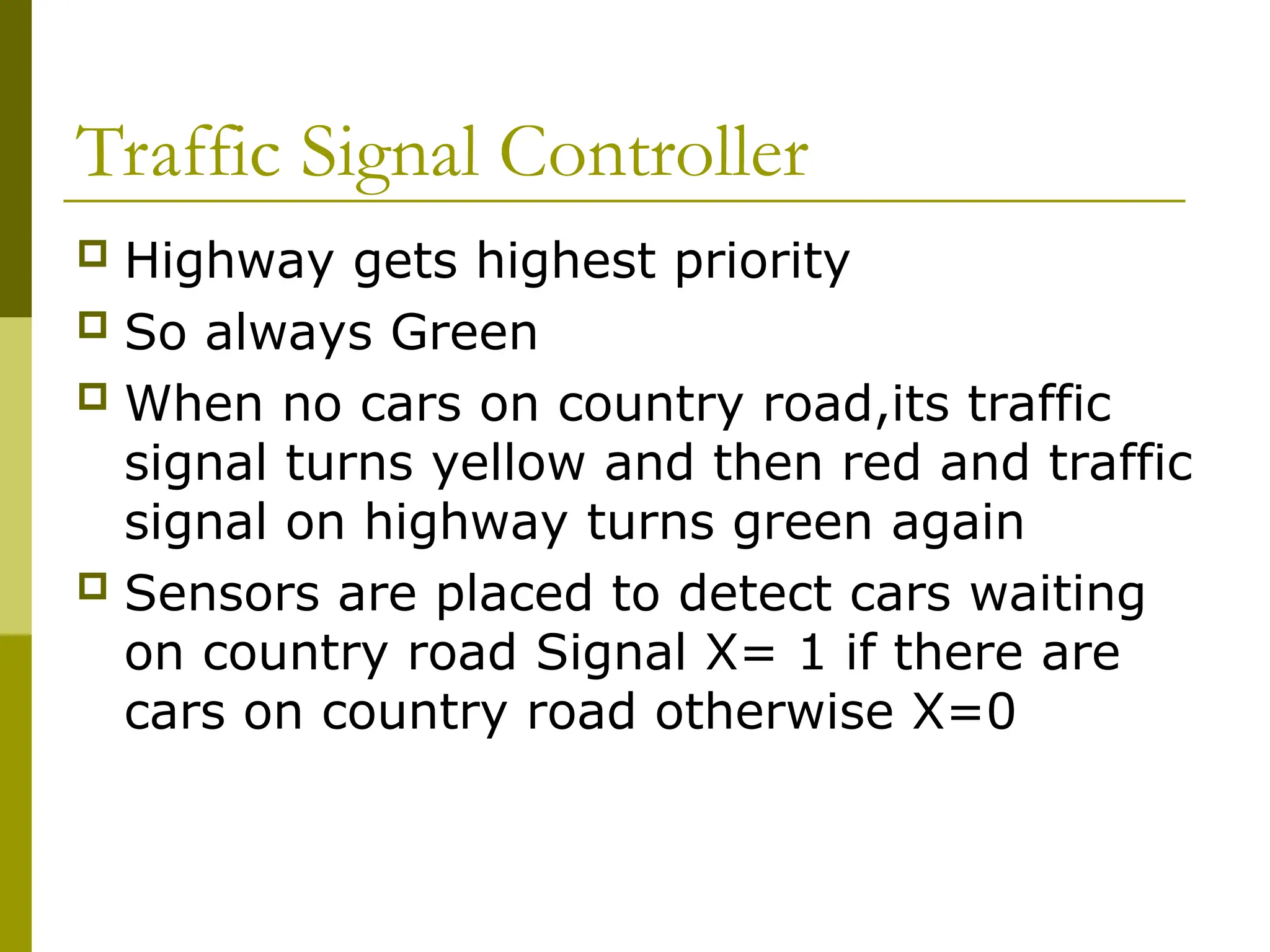
Traffic Signal Controller
Highway gets highest priority
So always Green
When no cars on country road,its traffic
signal turns yellow and then red and traffic
signal on highway turns green again
Sensors are placed to detect cars waiting
on country road Signal X= 1 if there are
cars on country road otherwise X=0
59.
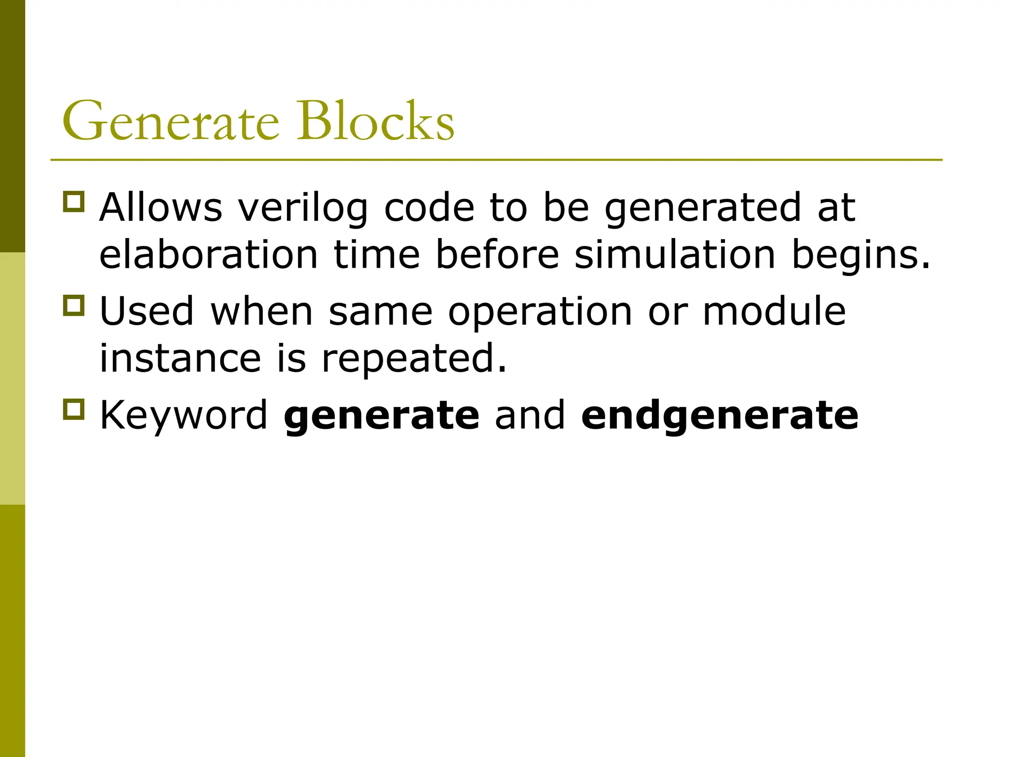
Generate Blocks
Allowsverilog code to be generated at
elaboration time before simulation begins.
Used when same operation or module
instance is repeated.
Keyword generate and endgenerate
60.
Contd.
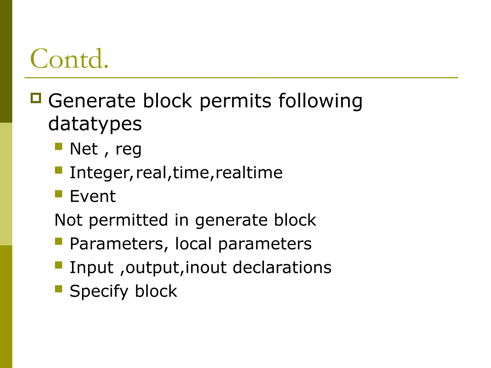
Generate blockpermits following
datatypes
Net , reg
Integer,real,time,realtime
Event
Not permitted in generate block
Parameters, local parameters
Input ,output,inout declarations
Specify block
Generate loop
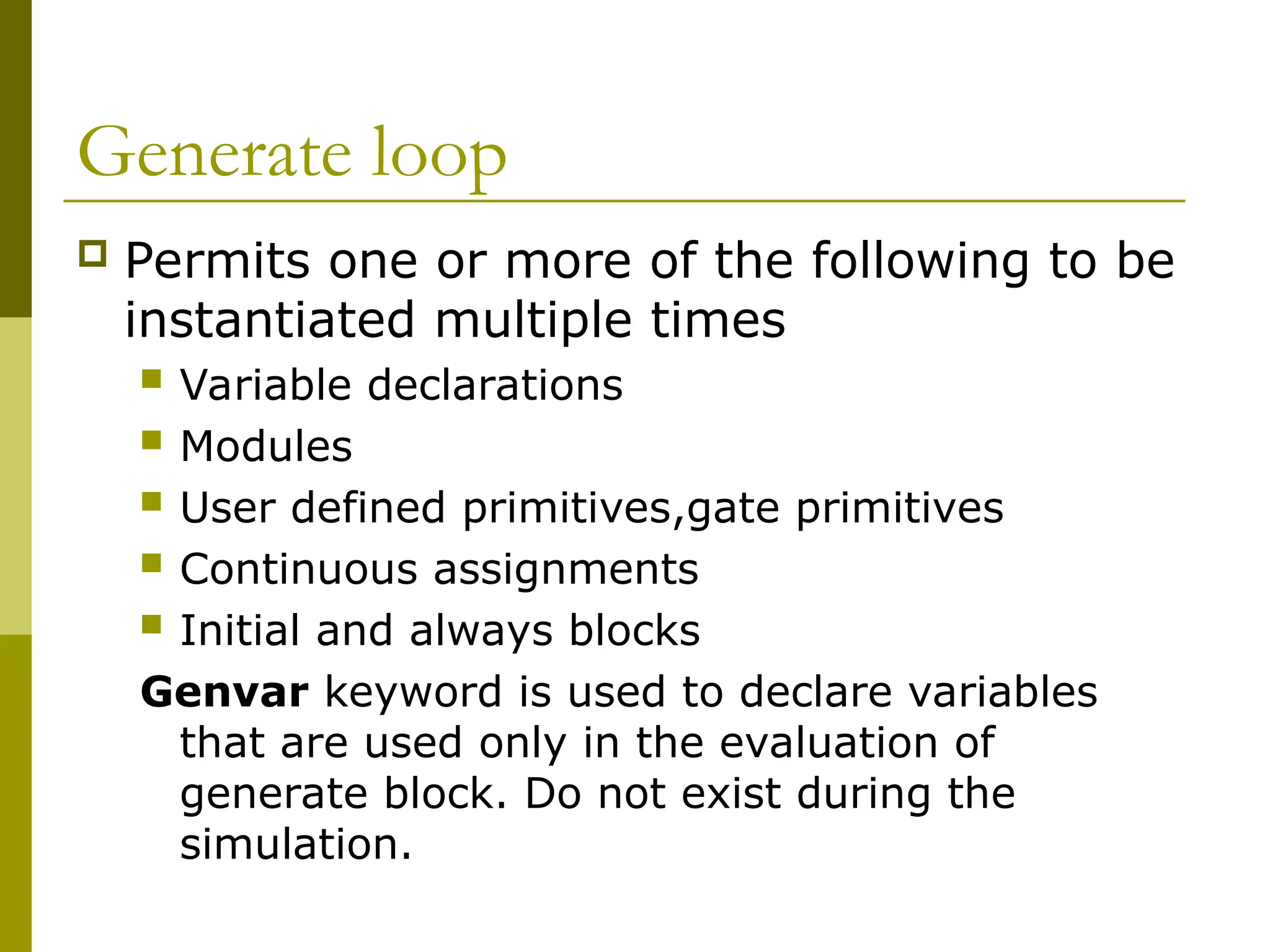
Permitsone or more of the following to be
instantiated multiple times
Variable declarations
Modules
User defined primitives,gate primitives
Continuous assignments
Initial and always blocks
Genvar keyword is used to declare variables
that are used only in the evaluation of
generate block. Do not exist during the
simulation.
63.
Example
module bitwise_xor(out,i1,i0);
parameter n=32;
output[n-1:0] out;
input [n-1:0] i1,i0;
genvar j;
generate for (j=0;j<n;j=j+1)
begin : xor_loop //unique identifier used for referencing
//hierarchically xor_loop[0].g1,xor_loop[1].g2….31
xor g1 (out[j],i1[j],i0[j]);
end
Endgenerate
64.
Contd….
Alternative style
reg[n-1:0]out;
generate for (j=0;j<n;j=j+1)
begin:bit
always @ (i1[j] or i0[j])
out[j]= i1[j] ^ i0[j];
end
endgenerate
65.
Home work
Writea program for 4bit riplle carry adder
using gate level modeling . Use generate
construct of verilog.
66.
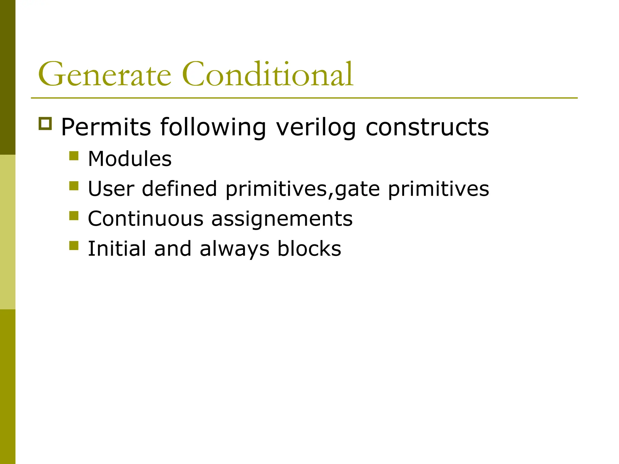
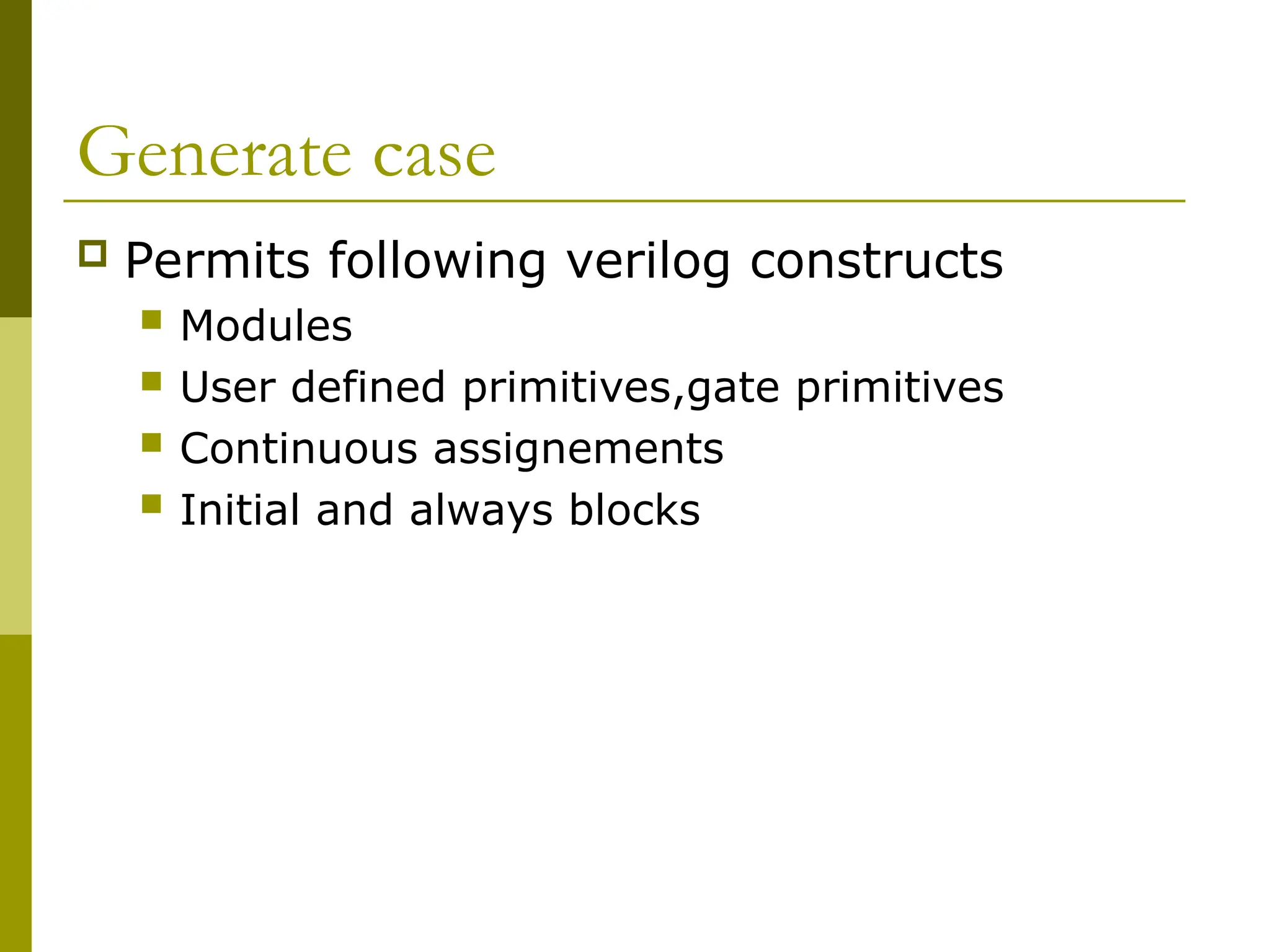
Generate Conditional
Permitsfollowing verilog constructs
Modules
User defined primitives,gate primitives
Continuous assignements
Initial and always blocks
![Declarartion and Initialization
Combined variable declarartion and initialization
ex.
Reg clock;
initial clock =0;
or
reg clock =0; // allowed only for variables which are declared at the
module
// level
Combined Port declaration and initialization
ex. module rca (sum,cout,a,b,cin);
output reg [3:0] sum =0;//initialize 4 bit output sum
output reg cout = 0;
input [3:0] a,b;
input cin;
.
.
endmodule](https://image.slidesharecdn.com/behavioralmodeling-251115091336-d862e0ed/75/Behavioral-Modeling-using-Verilog-and-combinational-or-sequential-circuit-12-2048.jpg)
![Blocking Assignments
• Executed in the order they are specified in a sequential block
• Will not block execution of statements that follow in a parallal block.
• = is used to specify blocking statement
Ex.
reg x,y,z;
reg [15:0] rega,regb;
integer count;
initial
begin
X=0;
Y=1;
Z=1;
Count=0;
rega = 16’b0;
Regb=rega;
#15 rega[2]= 1’b1;
#10 regb[15:13] = {x,y,z}
Count = count +1;
end](https://image.slidesharecdn.com/behavioralmodeling-251115091336-d862e0ed/75/Behavioral-Modeling-using-Verilog-and-combinational-or-sequential-circuit-15-2048.jpg)
![Execution
Y=1 gets executed only after x=0 is
executed
Sequential execution if blocking
statements are used
Simulation for the execution
X=0 to regb=rega are executed at time 0
Rega[2] = 1 at time 15
regb[15:13] = {x,y,z} at time 25
count=count +1 at time 25](https://image.slidesharecdn.com/behavioralmodeling-251115091336-d862e0ed/75/Behavioral-Modeling-using-Verilog-and-combinational-or-sequential-circuit-16-2048.jpg)
![Example
reg x,y,z;
reg [15:0] rega,regb;
integer count;
initial
begin
X=0;
Y=1;
Z=1;
count=0;
rega = 16’b0;
regb=rega;
rega[2] <= #15 1’b1;
regb[15:13] <= #10 {x,y,z}
count< = count +1;
end](https://image.slidesharecdn.com/behavioralmodeling-251115091336-d862e0ed/75/Behavioral-Modeling-using-Verilog-and-combinational-or-sequential-circuit-18-2048.jpg)
![Execution
X=0 to regb=rega are executed sequentially at
time 0
Rega[2]= 1 is scheduled to execute after 15
units
Regb[15:13] = {x,y,z} is scheduled to execute
after 10 time units
Count = count +1 is scheduled to be executed
without any delay at time 0
Do not mix blocking and non blocking
assignment in the same always block
Used to model several concurrent data transfer
that take place after a common event.](https://image.slidesharecdn.com/behavioralmodeling-251115091336-d862e0ed/75/Behavioral-Modeling-using-Verilog-and-combinational-or-sequential-circuit-19-2048.jpg)
![Example
A increasing sequence of values on an output
reg [3:0] i, out1;
initial
begin
i = 0;
while (i <= 15)
begin
out1 = i;
#10 i = i + 1;
end
end](https://image.slidesharecdn.com/behavioralmodeling-251115091336-d862e0ed/75/Behavioral-Modeling-using-Verilog-and-combinational-or-sequential-circuit-36-2048.jpg)
![Example
A increasing sequence of values on an output
reg [3:0] i, out1;
initial
begin
for ( i = 0 ; i <= 15 ; i = i + 1 )
begin
out1 = i;
$display(“out1= %d”,out1);
#10;
end
end](https://image.slidesharecdn.com/behavioralmodeling-251115091336-d862e0ed/75/Behavioral-Modeling-using-Verilog-and-combinational-or-sequential-circuit-38-2048.jpg)
![Example
‘define my_states 15
integer state[0:’my_states-1];
integer i;
initial
begin
for(i=0;i<15;i=i+2)
state[i]=0;
for(i=1; i<15;i=i+2)
state[i]=1;
end](https://image.slidesharecdn.com/behavioralmodeling-251115091336-d862e0ed/75/Behavioral-Modeling-using-Verilog-and-combinational-or-sequential-circuit-39-2048.jpg)
![Example
reg x,y;
reg [1:0] z,w;
initial
begin
x=1’b0;
y=1’b1;
z= {x,y};
w={y,x};
end
//execution in order at time 0](https://image.slidesharecdn.com/behavioralmodeling-251115091336-d862e0ed/75/Behavioral-Modeling-using-Verilog-and-combinational-or-sequential-circuit-49-2048.jpg)
![Example
reg x,y;
reg [1:0] z,w;
initial
begin
x=1’b0; // at time 0
#5 y=1’b1; // at time 5
#10 z= {x,y}; // at time 15
#20 w={y,x}; // at time ?
end](https://image.slidesharecdn.com/behavioralmodeling-251115091336-d862e0ed/75/Behavioral-Modeling-using-Verilog-and-combinational-or-sequential-circuit-50-2048.jpg)
![Example
reg x,y;
reg [1:0] z,w;
initial
fork
x=1’b0; // at time 0
#5 y=1’b1; // at time 5
#10 z= {x,y}; //at time 10
#20 w={y,x}; // at time ?
join
// same result except time of simulation](https://image.slidesharecdn.com/behavioralmodeling-251115091336-d862e0ed/75/Behavioral-Modeling-using-Verilog-and-combinational-or-sequential-circuit-52-2048.jpg)
![Example – With Race Condition
reg x,y;
reg [1:0] z,w;
initial
fork
x=1’b0;
y=1’b1;
z= {x,y};
w={y,x};
join
// Execution depends upon Simulation
// implementation
// Limitation of simulators](https://image.slidesharecdn.com/behavioralmodeling-251115091336-d862e0ed/75/Behavioral-Modeling-using-Verilog-and-combinational-or-sequential-circuit-53-2048.jpg)
![Special Features of Blocks
Nested Blocks
reg x,y;
reg [1:0] z,w;
initial
begin
x=1’b0;
fork
#5 y=1’b1;
#10 z= {x,y};
join
#20 w={y,x};
end](https://image.slidesharecdn.com/behavioralmodeling-251115091336-d862e0ed/75/Behavioral-Modeling-using-Verilog-and-combinational-or-sequential-circuit-54-2048.jpg)
![Disabling Named blocks
Keyword disable can be used to get out of
the loops, error conditions etc
initial
begin
porta =8’h08;
i=0;
begin : block1
while (i<8)
begin if (porta[i])
begin
disable block1;
end](https://image.slidesharecdn.com/behavioralmodeling-251115091336-d862e0ed/75/Behavioral-Modeling-using-Verilog-and-combinational-or-sequential-circuit-56-2048.jpg)
![Example
initial
begin
porta =8’h08;
i=0;
begin : block1
while (i<8)
begin
if (porta[i])
begin
disable block1;
end
i=i+1;
end
end
end](https://image.slidesharecdn.com/behavioralmodeling-251115091336-d862e0ed/75/Behavioral-Modeling-using-Verilog-and-combinational-or-sequential-circuit-57-2048.jpg)
![Example
module bitwise_xor(out,i1,i0);
parameter n=32;
output [n-1:0] out;
input [n-1:0] i1,i0;
genvar j;
generate for (j=0;j<n;j=j+1)
begin : xor_loop //unique identifier used for referencing
//hierarchically xor_loop[0].g1,xor_loop[1].g2….31
xor g1 (out[j],i1[j],i0[j]);
end
Endgenerate](https://image.slidesharecdn.com/behavioralmodeling-251115091336-d862e0ed/75/Behavioral-Modeling-using-Verilog-and-combinational-or-sequential-circuit-63-2048.jpg)
![Contd….
Alternative style
reg [n-1:0]out;
generate for (j=0;j<n;j=j+1)
begin:bit
always @ (i1[j] or i0[j])
out[j]= i1[j] ^ i0[j];
end
endgenerate](https://image.slidesharecdn.com/behavioralmodeling-251115091336-d862e0ed/75/Behavioral-Modeling-using-Verilog-and-combinational-or-sequential-circuit-64-2048.jpg)
![Example
module multiplier(product,a0,a1);
parameter a0w =8;
parameter a1w=8;
localparam pro_width =a0w +a1w;
output [pro_width-1:0] product;
input [a0w-1:0]a0;
output[a1w-1:0]a1;
generate
if((a0w<8) || (a1w<8))
clamult m0 (product,a0,a1);
else
treemult m0(product,a0,a1);
endgenerate
endmodule](https://image.slidesharecdn.com/behavioralmodeling-251115091336-d862e0ed/75/Behavioral-Modeling-using-Verilog-and-combinational-or-sequential-circuit-67-2048.jpg)
![N bit Adder using generate case
module adder(c0,sum,b1,a1,ci);
parameter n=4;
output [n-1:0] sum;
output co;
input [n-1:0]a1,b1;
input ci;
generate
case(n)
1: adder1 ab1(co,sum,b1,a1,ci);
2: adder2 ab2(co,sum,b1,a1,ci);
default: addercla ab3(co,sum,b1,a1,ci);
endcase
endgenerate
endmodule](https://image.slidesharecdn.com/behavioralmodeling-251115091336-d862e0ed/75/Behavioral-Modeling-using-Verilog-and-combinational-or-sequential-circuit-69-2048.jpg)


![Declarartion and Initialization
Combined variable declarartion and initialization
ex.
Reg clock;
initial clock =0;
or
reg clock =0; // allowed only for variables which are declared at the
module
// level
Combined Port declaration and initialization
ex. module rca (sum,cout,a,b,cin);
output reg [3:0] sum =0;//initialize 4 bit output sum
output reg cout = 0;
input [3:0] a,b;
input cin;
.
.
endmodule](https://crownmelresort.com/image.slidesharecdn.com/behavioralmodeling-251115091336-d862e0ed/75/Behavioral-Modeling-using-Verilog-and-combinational-or-sequential-circuit-12-2048.jpg)


![Blocking Assignments
• Executed in the order they are specified in a sequential block
• Will not block execution of statements that follow in a parallal block.
• = is used to specify blocking statement
Ex.
reg x,y,z;
reg [15:0] rega,regb;
integer count;
initial
begin
X=0;
Y=1;
Z=1;
Count=0;
rega = 16’b0;
Regb=rega;
#15 rega[2]= 1’b1;
#10 regb[15:13] = {x,y,z}
Count = count +1;
end](https://crownmelresort.com/image.slidesharecdn.com/behavioralmodeling-251115091336-d862e0ed/75/Behavioral-Modeling-using-Verilog-and-combinational-or-sequential-circuit-15-2048.jpg)
![Execution
Y=1 gets executed only after x=0 is
executed
Sequential execution if blocking
statements are used
Simulation for the execution
X=0 to regb=rega are executed at time 0
Rega[2] = 1 at time 15
regb[15:13] = {x,y,z} at time 25
count=count +1 at time 25](https://crownmelresort.com/image.slidesharecdn.com/behavioralmodeling-251115091336-d862e0ed/75/Behavioral-Modeling-using-Verilog-and-combinational-or-sequential-circuit-16-2048.jpg)

![Example
reg x,y,z;
reg [15:0] rega,regb;
integer count;
initial
begin
X=0;
Y=1;
Z=1;
count=0;
rega = 16’b0;
regb=rega;
rega[2] <= #15 1’b1;
regb[15:13] <= #10 {x,y,z}
count< = count +1;
end](https://crownmelresort.com/image.slidesharecdn.com/behavioralmodeling-251115091336-d862e0ed/75/Behavioral-Modeling-using-Verilog-and-combinational-or-sequential-circuit-18-2048.jpg)
![Execution
X=0 to regb=rega are executed sequentially at
time 0
Rega[2]= 1 is scheduled to execute after 15
units
Regb[15:13] = {x,y,z} is scheduled to execute
after 10 time units
Count = count +1 is scheduled to be executed
without any delay at time 0
Do not mix blocking and non blocking
assignment in the same always block
Used to model several concurrent data transfer
that take place after a common event.](https://crownmelresort.com/image.slidesharecdn.com/behavioralmodeling-251115091336-d862e0ed/75/Behavioral-Modeling-using-Verilog-and-combinational-or-sequential-circuit-19-2048.jpg)


![Example
A increasing sequence of values on an output
reg [3:0] i, out1;
initial
begin
i = 0;
while (i <= 15)
begin
out1 = i;
#10 i = i + 1;
end
end](https://crownmelresort.com/image.slidesharecdn.com/behavioralmodeling-251115091336-d862e0ed/75/Behavioral-Modeling-using-Verilog-and-combinational-or-sequential-circuit-36-2048.jpg)

![Example
A increasing sequence of values on an output
reg [3:0] i, out1;
initial
begin
for ( i = 0 ; i <= 15 ; i = i + 1 )
begin
out1 = i;
$display(“out1= %d”,out1);
#10;
end
end](https://crownmelresort.com/image.slidesharecdn.com/behavioralmodeling-251115091336-d862e0ed/75/Behavioral-Modeling-using-Verilog-and-combinational-or-sequential-circuit-38-2048.jpg)
![Example
‘define my_states 15
integer state[0:’my_states-1];
integer i;
initial
begin
for(i=0;i<15;i=i+2)
state[i]=0;
for(i=1; i<15;i=i+2)
state[i]=1;
end](https://crownmelresort.com/image.slidesharecdn.com/behavioralmodeling-251115091336-d862e0ed/75/Behavioral-Modeling-using-Verilog-and-combinational-or-sequential-circuit-39-2048.jpg)


![Example
reg x,y;
reg [1:0] z,w;
initial
begin
x=1’b0;
y=1’b1;
z= {x,y};
w={y,x};
end
//execution in order at time 0](https://crownmelresort.com/image.slidesharecdn.com/behavioralmodeling-251115091336-d862e0ed/75/Behavioral-Modeling-using-Verilog-and-combinational-or-sequential-circuit-49-2048.jpg)
![Example
reg x,y;
reg [1:0] z,w;
initial
begin
x=1’b0; // at time 0
#5 y=1’b1; // at time 5
#10 z= {x,y}; // at time 15
#20 w={y,x}; // at time ?
end](https://crownmelresort.com/image.slidesharecdn.com/behavioralmodeling-251115091336-d862e0ed/75/Behavioral-Modeling-using-Verilog-and-combinational-or-sequential-circuit-50-2048.jpg)

![Example
reg x,y;
reg [1:0] z,w;
initial
fork
x=1’b0; // at time 0
#5 y=1’b1; // at time 5
#10 z= {x,y}; //at time 10
#20 w={y,x}; // at time ?
join
// same result except time of simulation](https://crownmelresort.com/image.slidesharecdn.com/behavioralmodeling-251115091336-d862e0ed/75/Behavioral-Modeling-using-Verilog-and-combinational-or-sequential-circuit-52-2048.jpg)
![Example – With Race Condition
reg x,y;
reg [1:0] z,w;
initial
fork
x=1’b0;
y=1’b1;
z= {x,y};
w={y,x};
join
// Execution depends upon Simulation
// implementation
// Limitation of simulators](https://crownmelresort.com/image.slidesharecdn.com/behavioralmodeling-251115091336-d862e0ed/75/Behavioral-Modeling-using-Verilog-and-combinational-or-sequential-circuit-53-2048.jpg)
![Special Features of Blocks
Nested Blocks
reg x,y;
reg [1:0] z,w;
initial
begin
x=1’b0;
fork
#5 y=1’b1;
#10 z= {x,y};
join
#20 w={y,x};
end](https://crownmelresort.com/image.slidesharecdn.com/behavioralmodeling-251115091336-d862e0ed/75/Behavioral-Modeling-using-Verilog-and-combinational-or-sequential-circuit-54-2048.jpg)

![Disabling Named blocks
Keyword disable can be used to get out of
the loops, error conditions etc
initial
begin
porta =8’h08;
i=0;
begin : block1
while (i<8)
begin if (porta[i])
begin
disable block1;
end](https://crownmelresort.com/image.slidesharecdn.com/behavioralmodeling-251115091336-d862e0ed/75/Behavioral-Modeling-using-Verilog-and-combinational-or-sequential-circuit-56-2048.jpg)
![Example
initial
begin
porta =8’h08;
i=0;
begin : block1
while (i<8)
begin
if (porta[i])
begin
disable block1;
end
i=i+1;
end
end
end](https://crownmelresort.com/image.slidesharecdn.com/behavioralmodeling-251115091336-d862e0ed/75/Behavioral-Modeling-using-Verilog-and-combinational-or-sequential-circuit-57-2048.jpg)


![Example
module bitwise_xor(out,i1,i0);
parameter n=32;
output [n-1:0] out;
input [n-1:0] i1,i0;
genvar j;
generate for (j=0;j<n;j=j+1)
begin : xor_loop //unique identifier used for referencing
//hierarchically xor_loop[0].g1,xor_loop[1].g2….31
xor g1 (out[j],i1[j],i0[j]);
end
Endgenerate](https://crownmelresort.com/image.slidesharecdn.com/behavioralmodeling-251115091336-d862e0ed/75/Behavioral-Modeling-using-Verilog-and-combinational-or-sequential-circuit-63-2048.jpg)
![Contd….
Alternative style
reg [n-1:0]out;
generate for (j=0;j<n;j=j+1)
begin:bit
always @ (i1[j] or i0[j])
out[j]= i1[j] ^ i0[j];
end
endgenerate](https://crownmelresort.com/image.slidesharecdn.com/behavioralmodeling-251115091336-d862e0ed/75/Behavioral-Modeling-using-Verilog-and-combinational-or-sequential-circuit-64-2048.jpg)


![Example
module multiplier(product,a0,a1);
parameter a0w =8;
parameter a1w=8;
localparam pro_width =a0w +a1w;
output [pro_width-1:0] product;
input [a0w-1:0]a0;
output[a1w-1:0]a1;
generate
if((a0w<8) || (a1w<8))
clamult m0 (product,a0,a1);
else
treemult m0(product,a0,a1);
endgenerate
endmodule](https://crownmelresort.com/image.slidesharecdn.com/behavioralmodeling-251115091336-d862e0ed/75/Behavioral-Modeling-using-Verilog-and-combinational-or-sequential-circuit-67-2048.jpg)

![N bit Adder using generate case
module adder(c0,sum,b1,a1,ci);
parameter n=4;
output [n-1:0] sum;
output co;
input [n-1:0]a1,b1;
input ci;
generate
case(n)
1: adder1 ab1(co,sum,b1,a1,ci);
2: adder2 ab2(co,sum,b1,a1,ci);
default: addercla ab3(co,sum,b1,a1,ci);
endcase
endgenerate
endmodule](https://crownmelresort.com/image.slidesharecdn.com/behavioralmodeling-251115091336-d862e0ed/75/Behavioral-Modeling-using-Verilog-and-combinational-or-sequential-circuit-69-2048.jpg)