Download to read offline


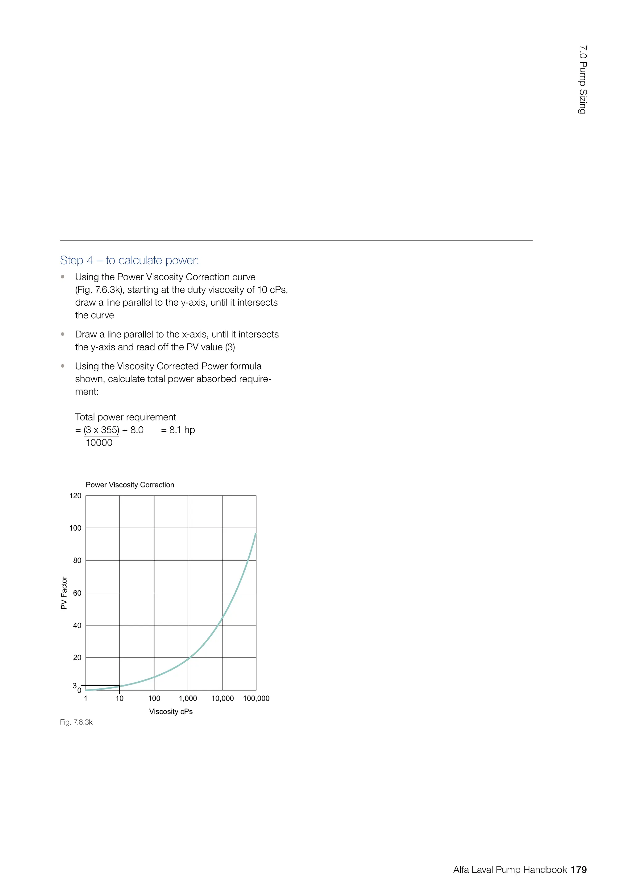
![Speed/Capacity: Q1 = n1 ⇒ n2 = n1 x Q2
Q2 n2 Q1
[rev/min]
Speed/Head: H1 = n1
2
⇒ n2 = n1 x
H2 n2
2
[rev/min]
Speed/Power P1 = n1
3
⇒ n2 = n1 x
P2 n2
3
[rev/min]
√
3 P2
P1
√H2
H1
√c-b
a-b
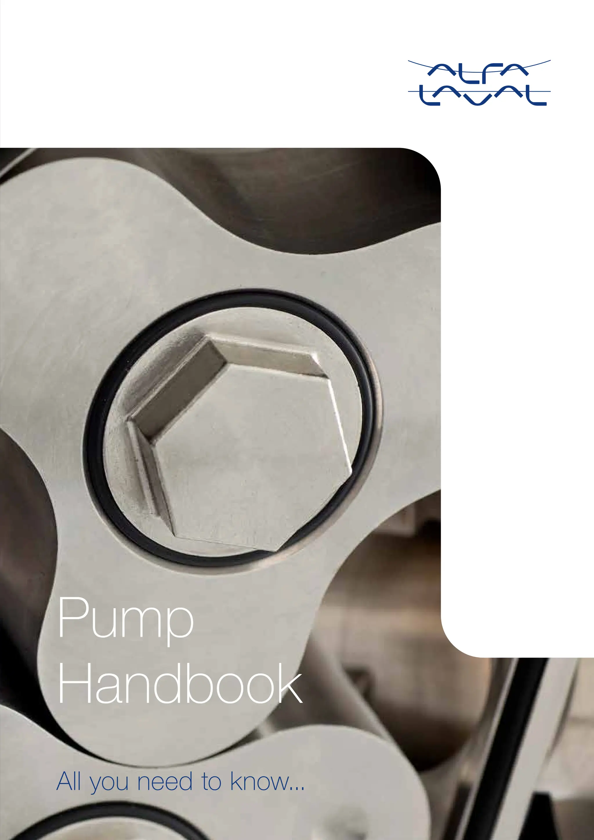
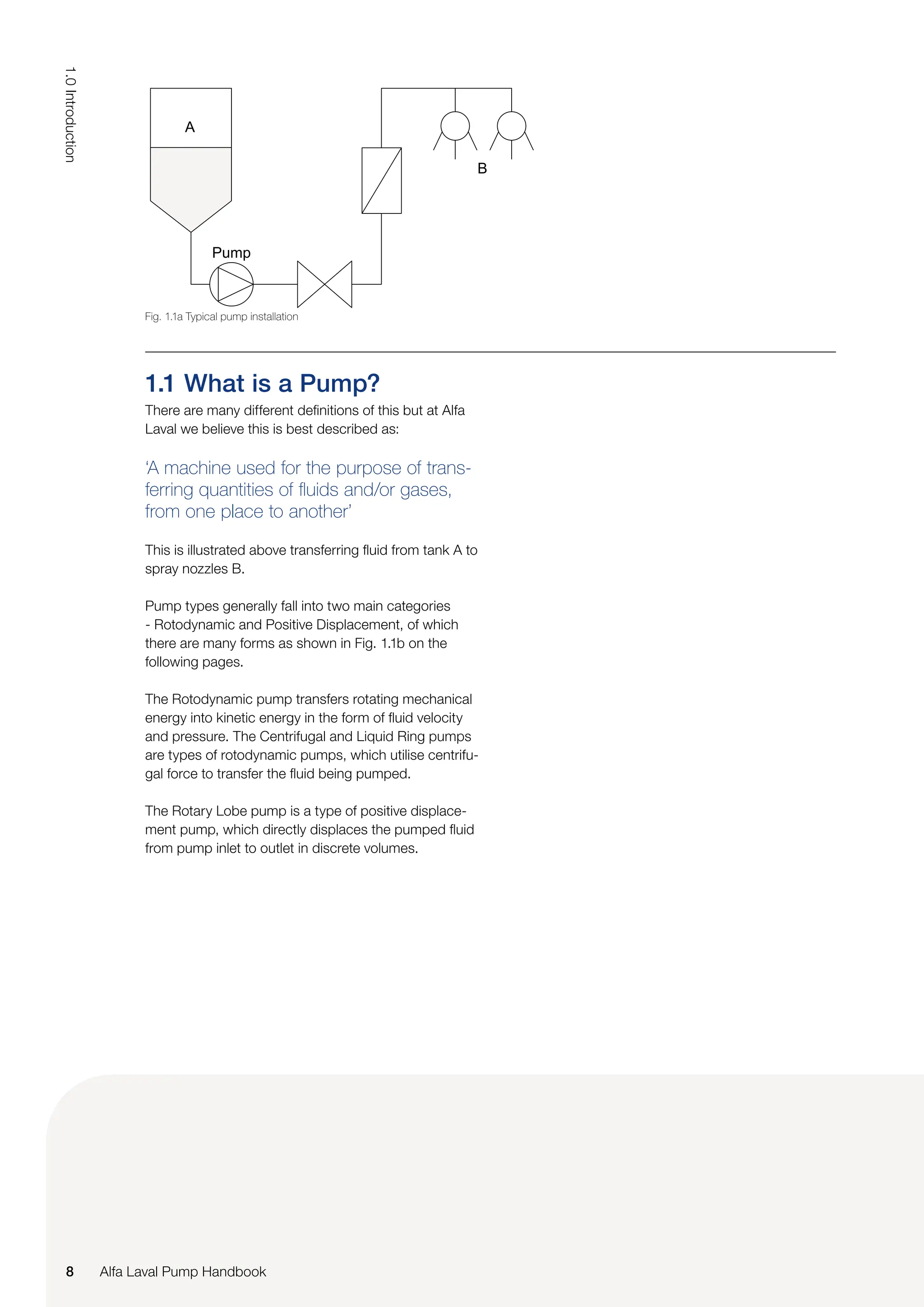
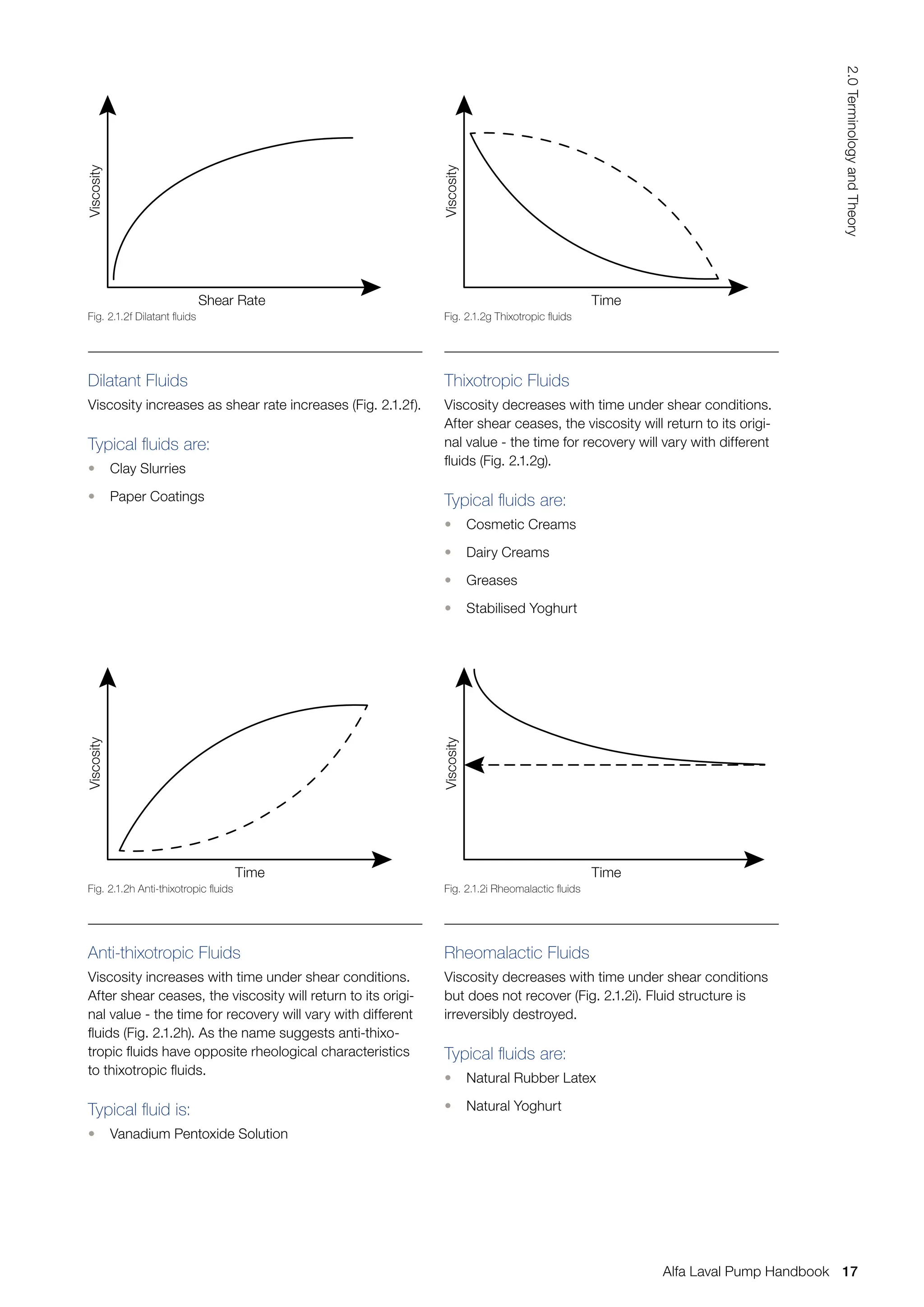
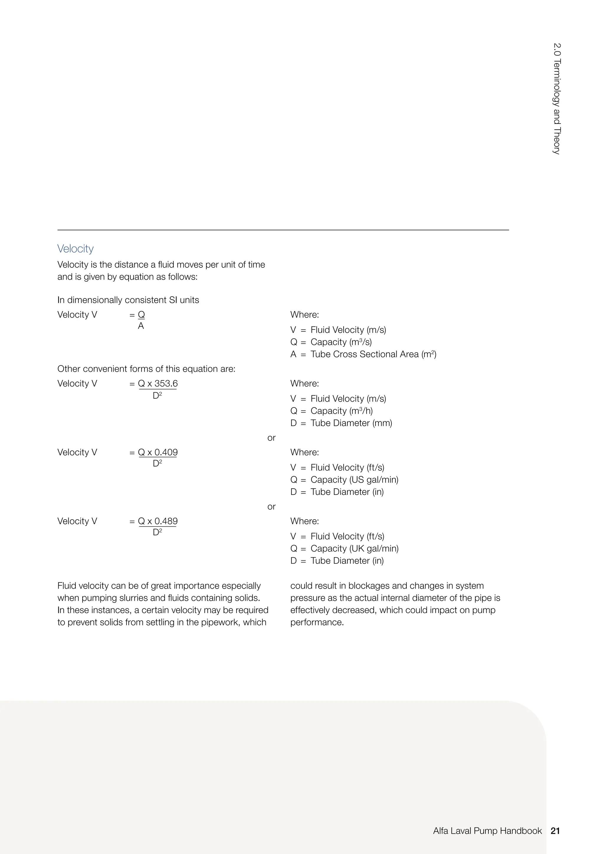
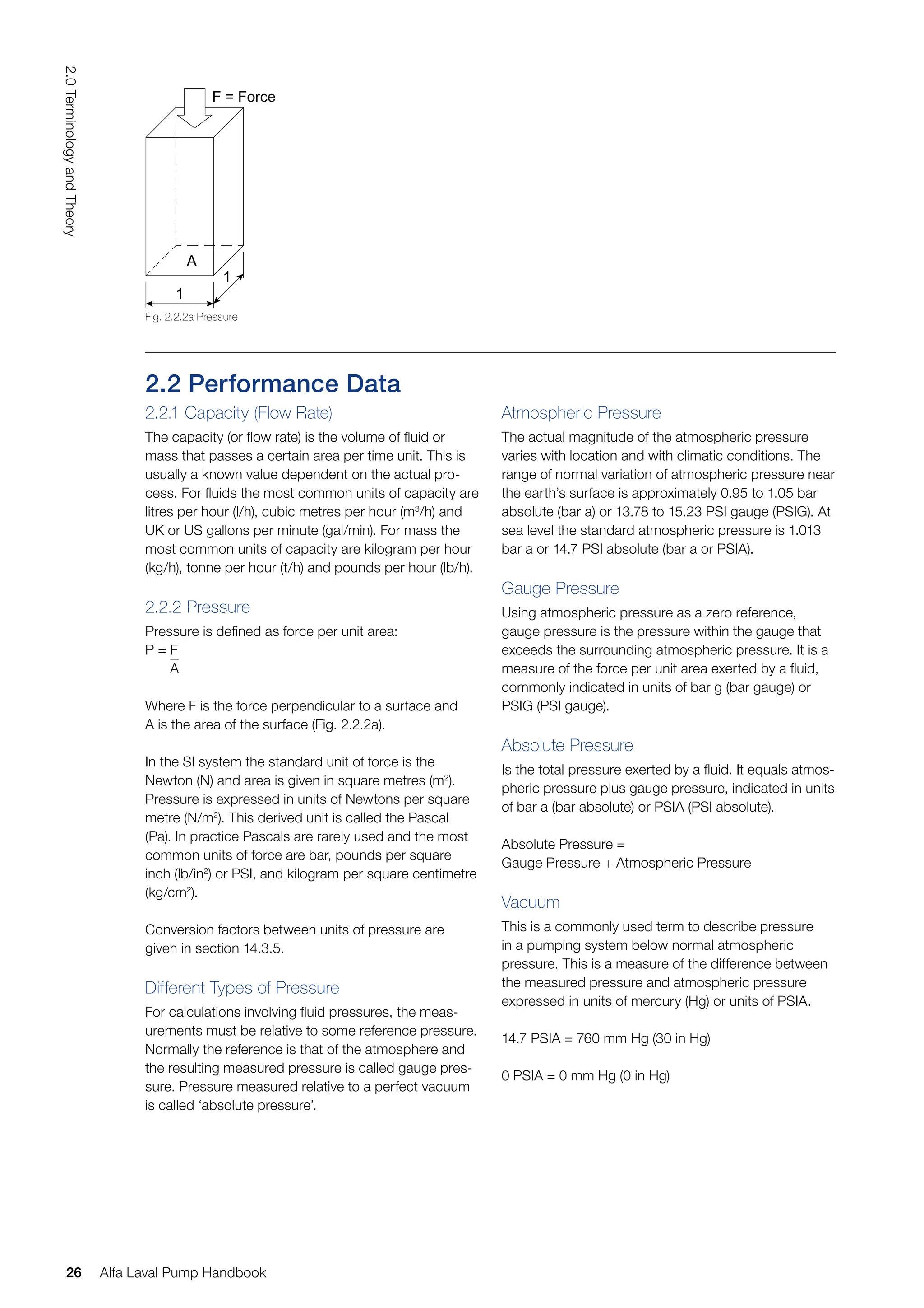
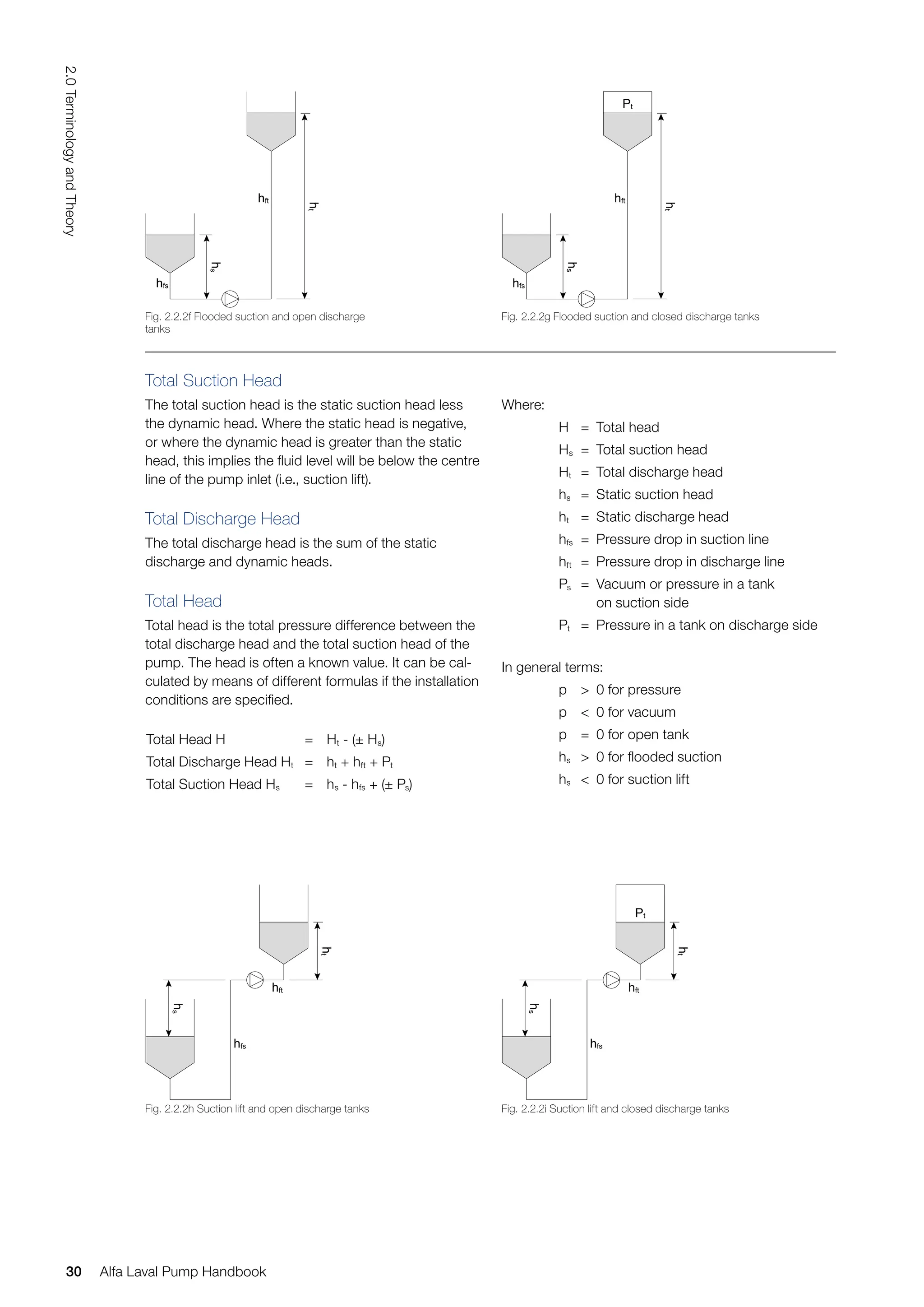
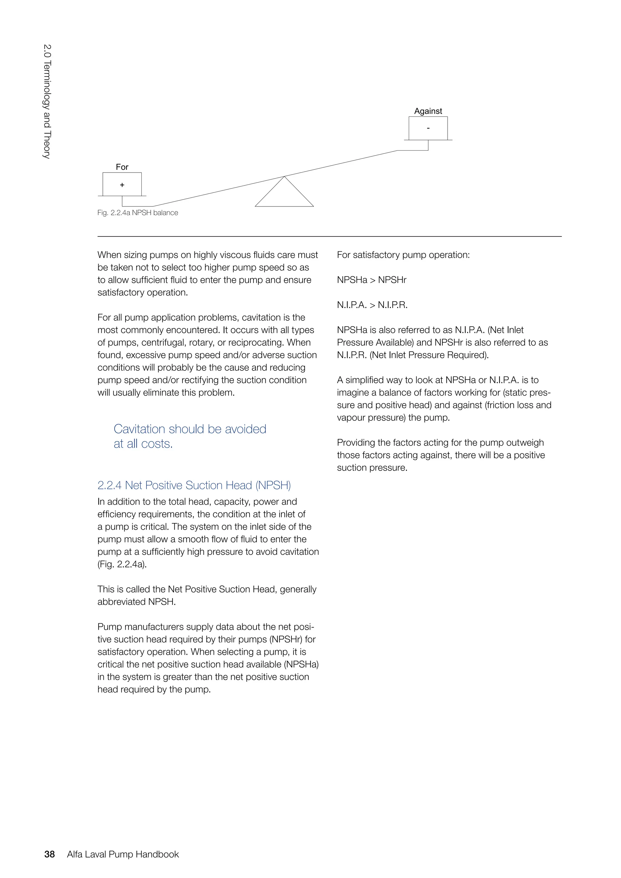
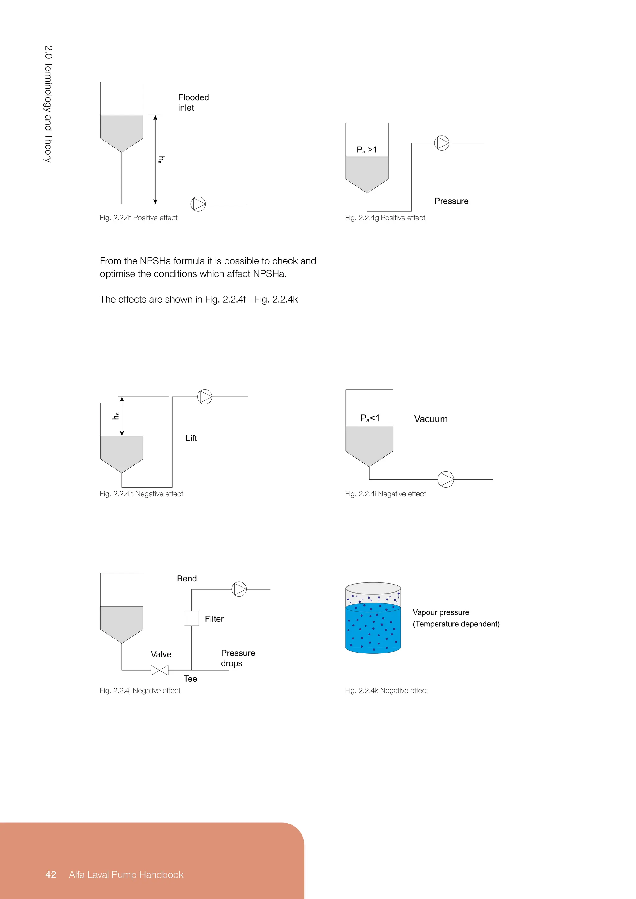
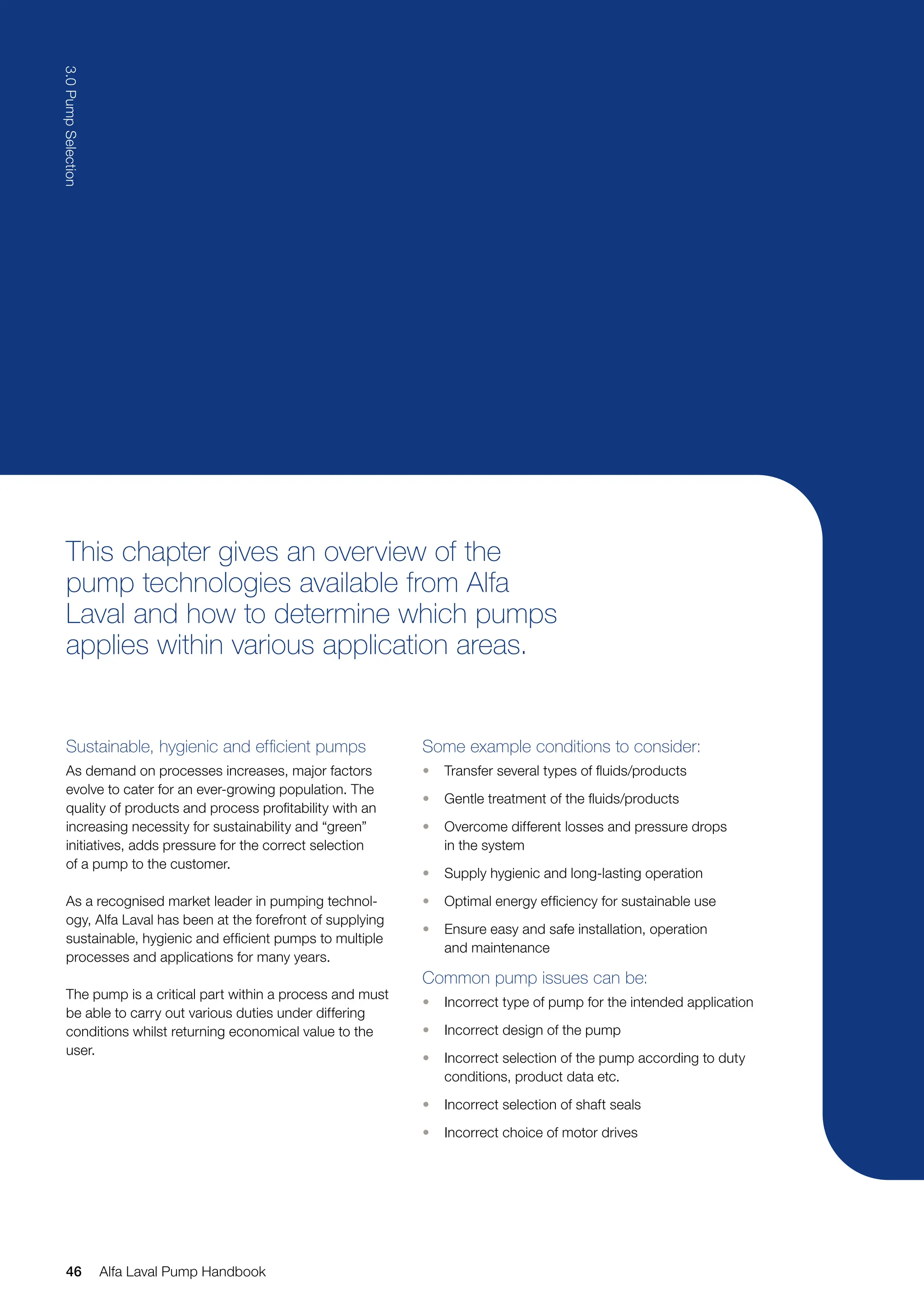
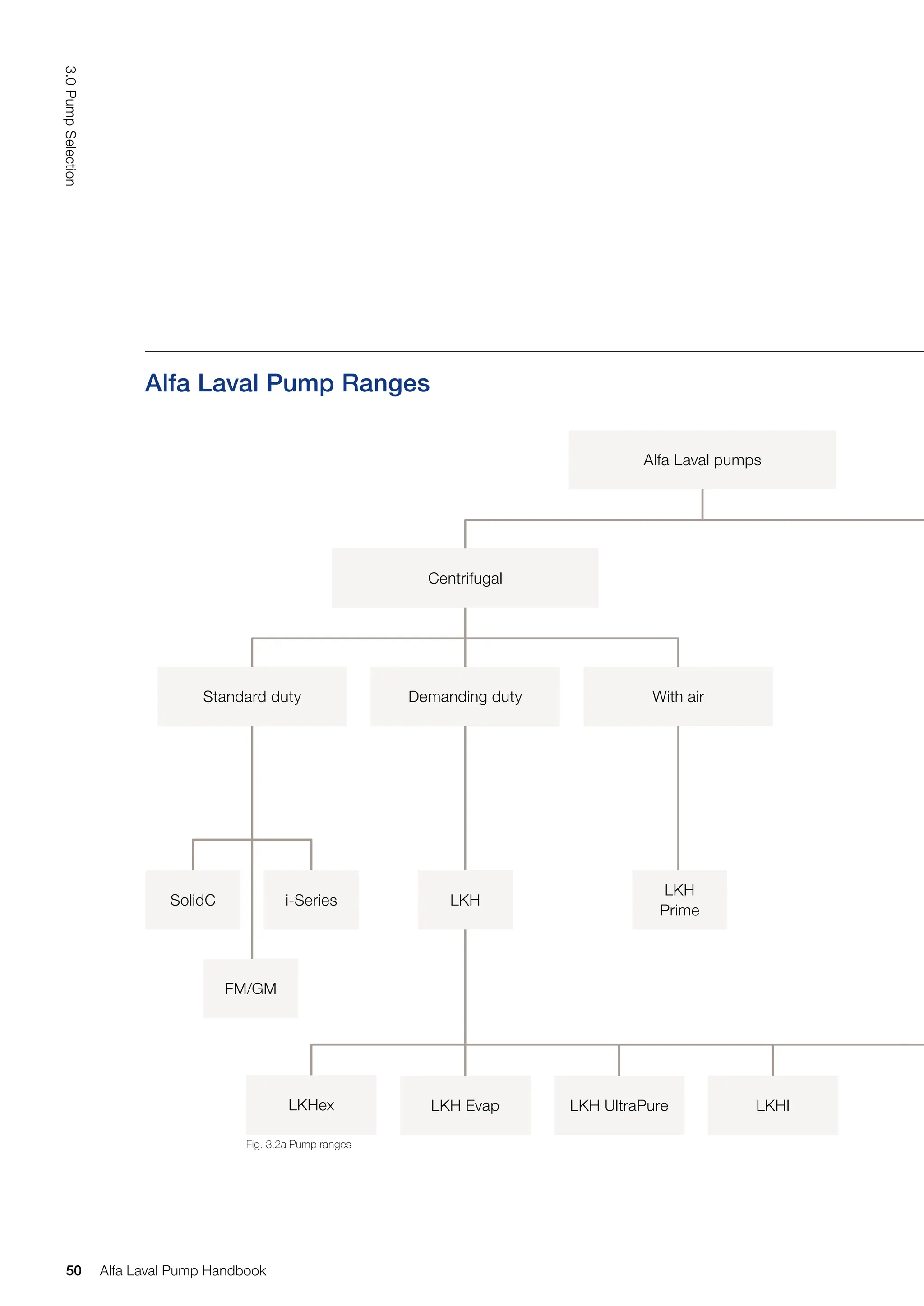
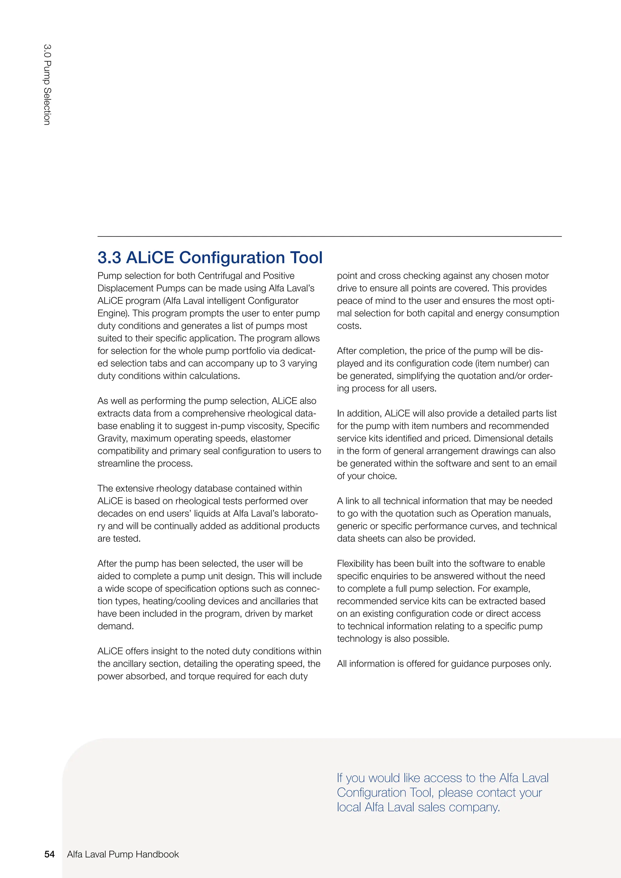
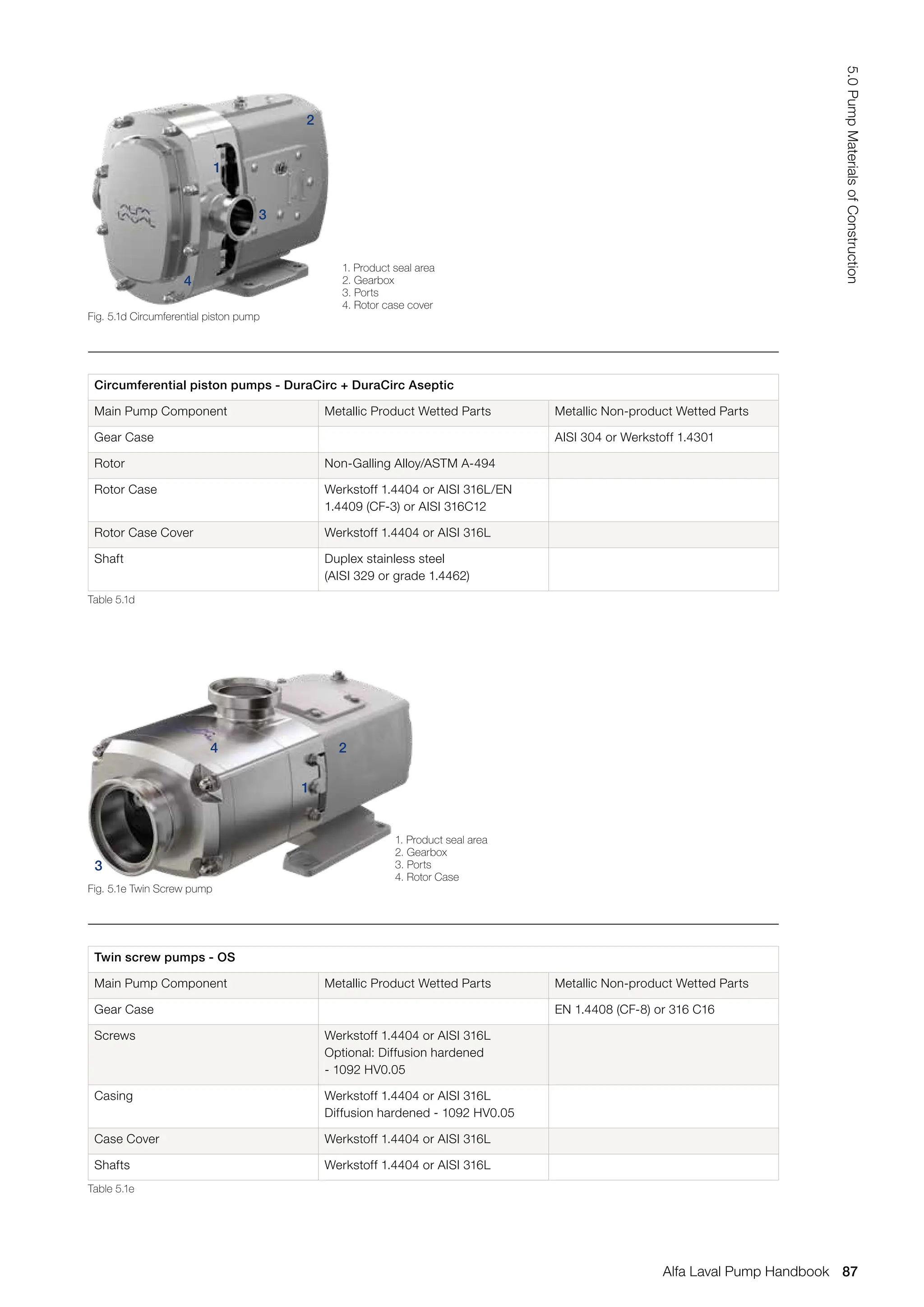
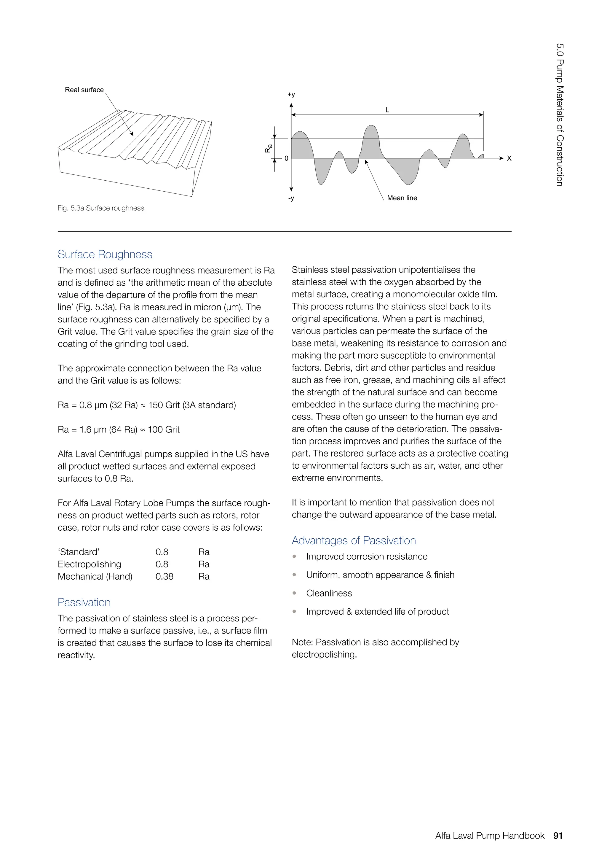
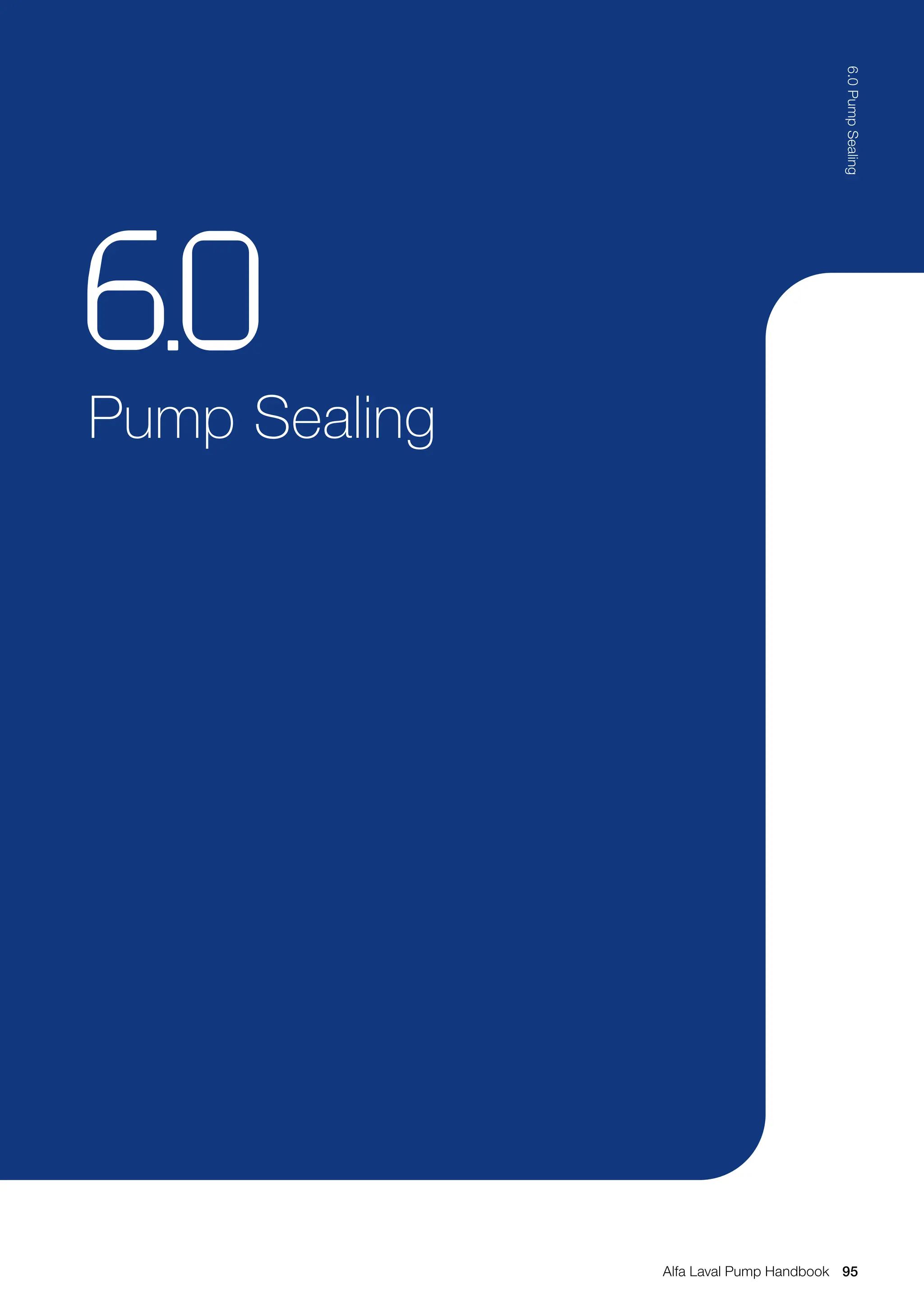
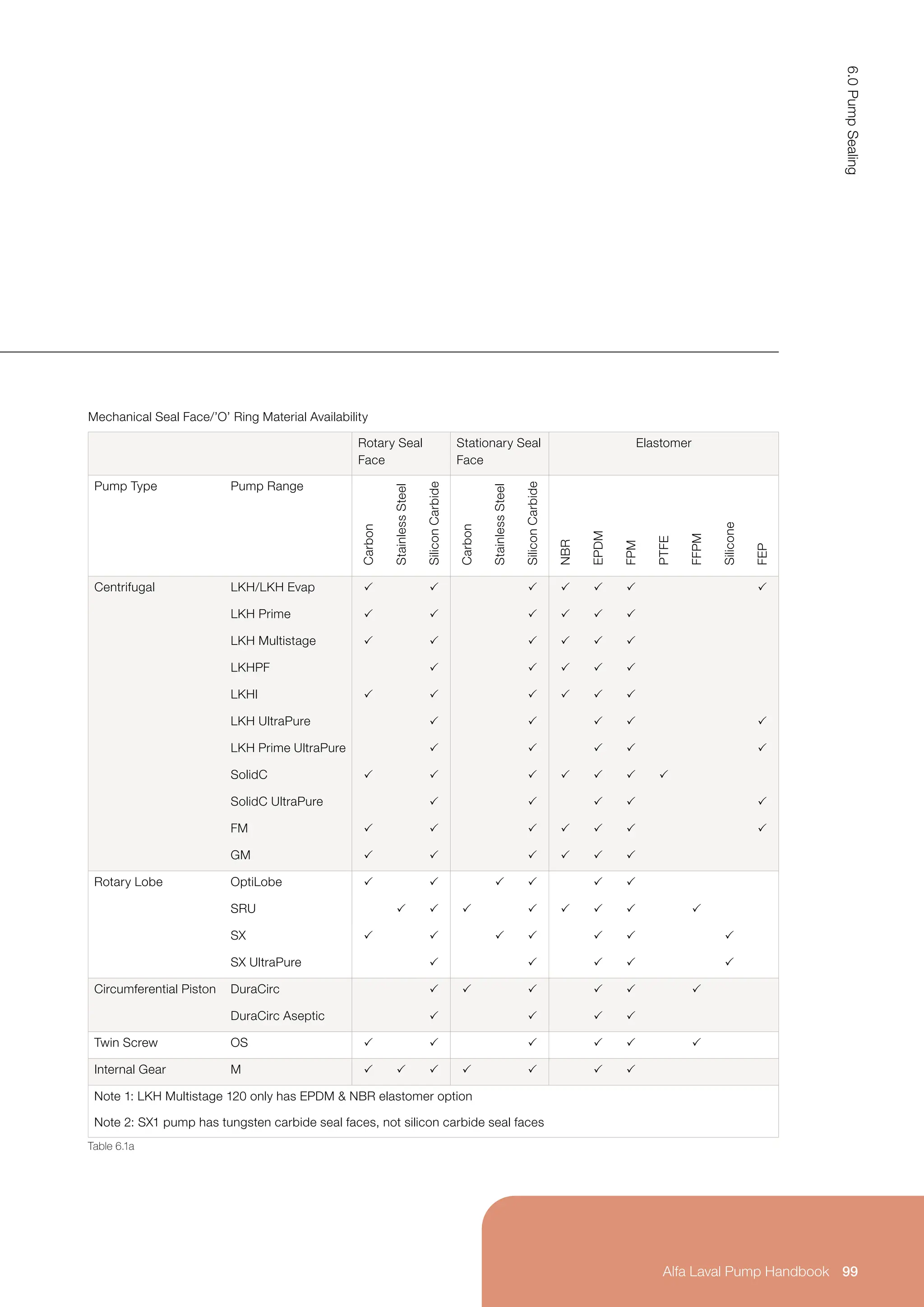
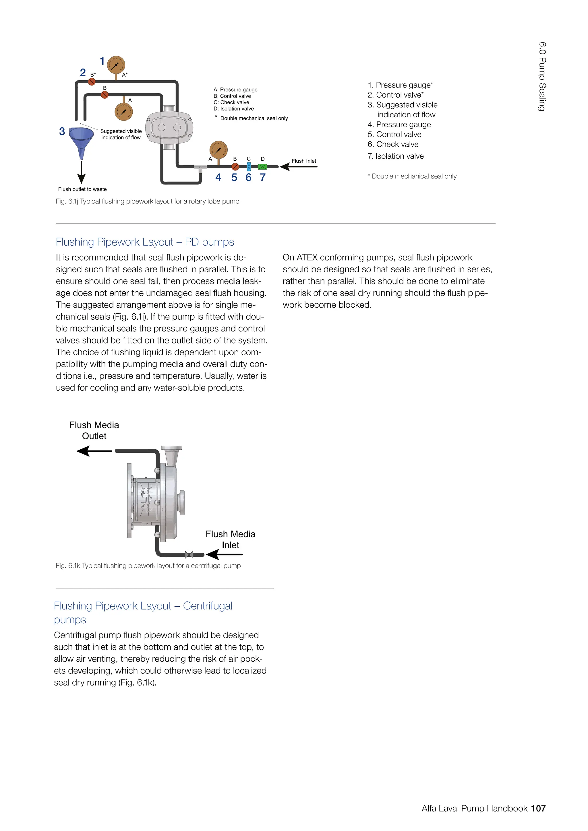
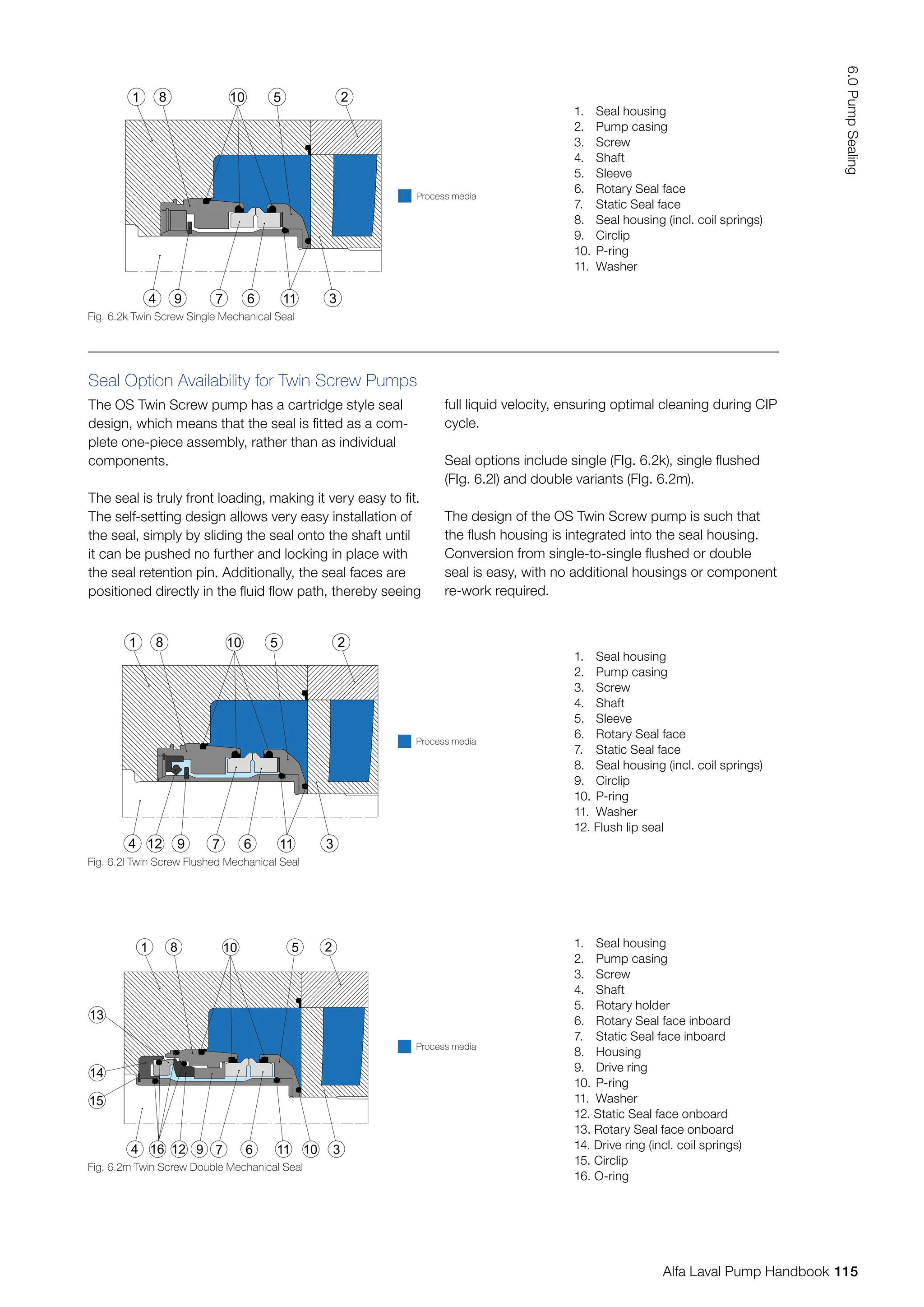
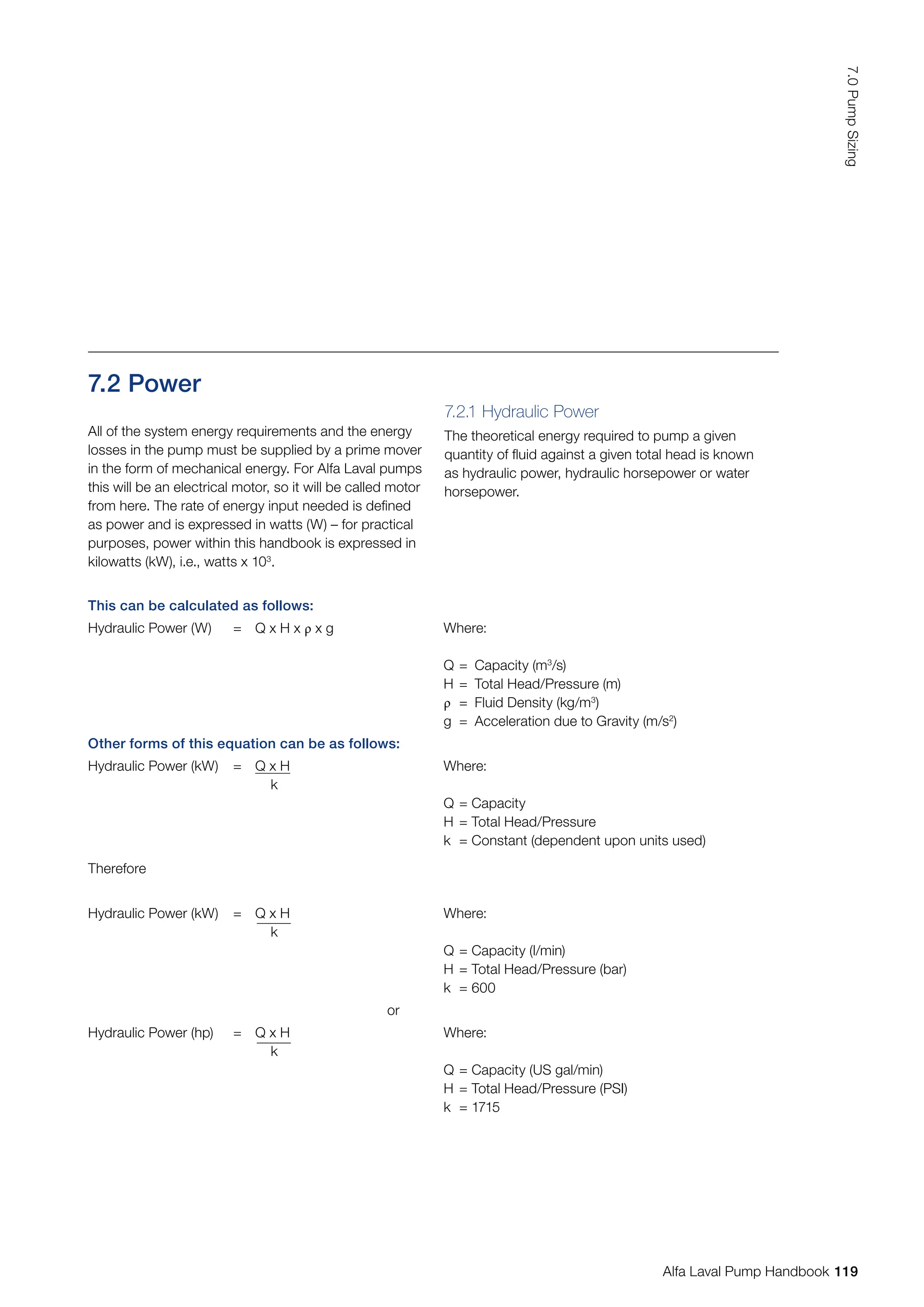
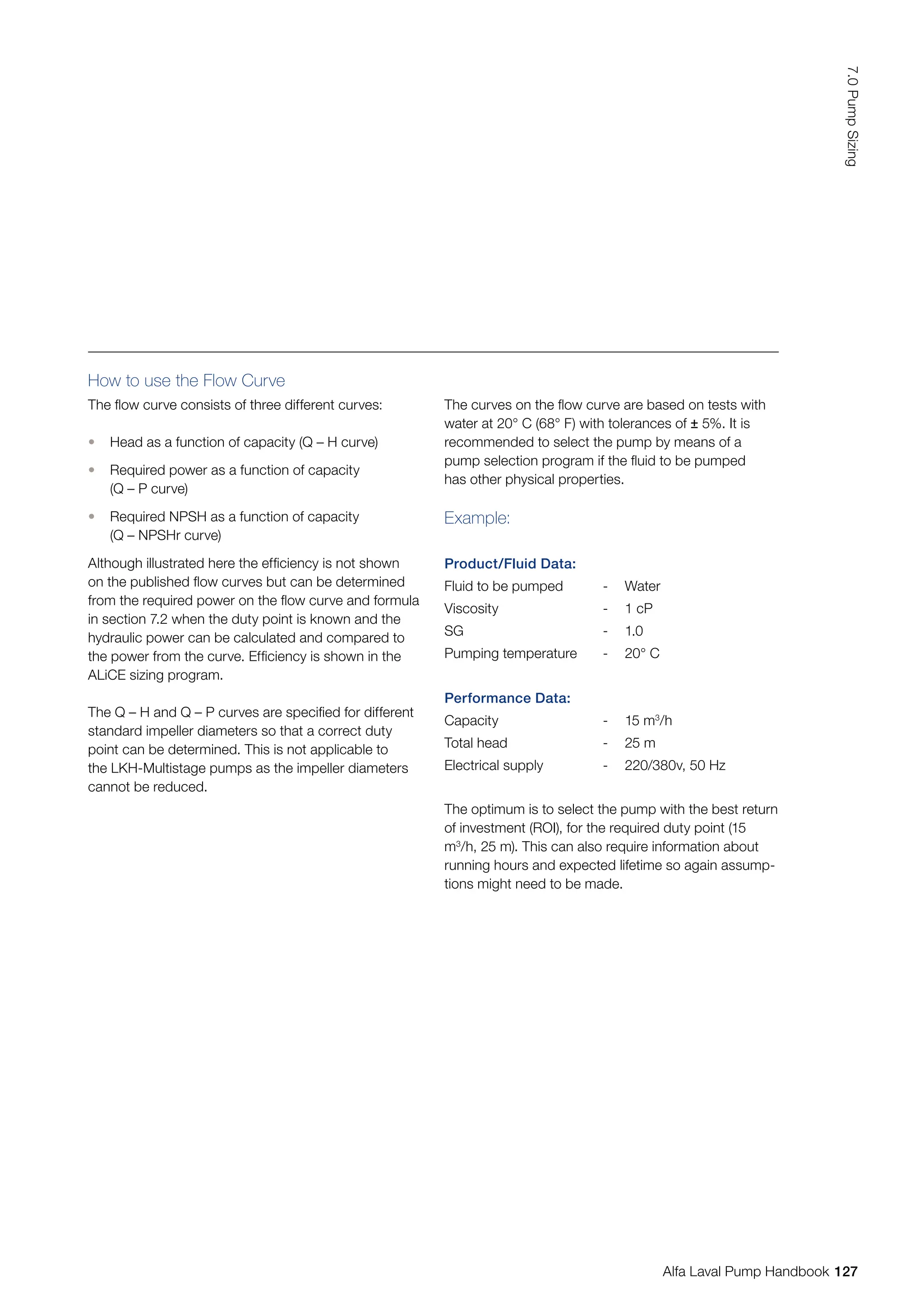
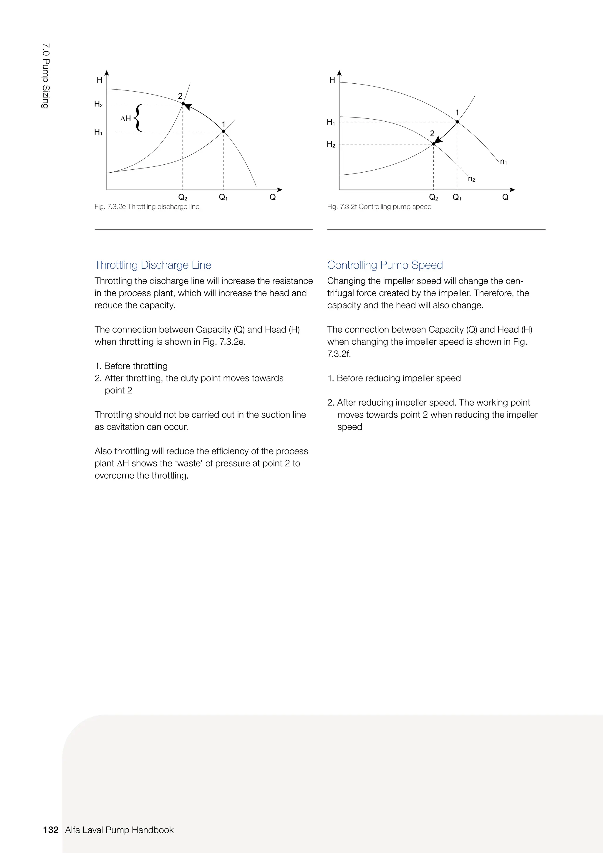
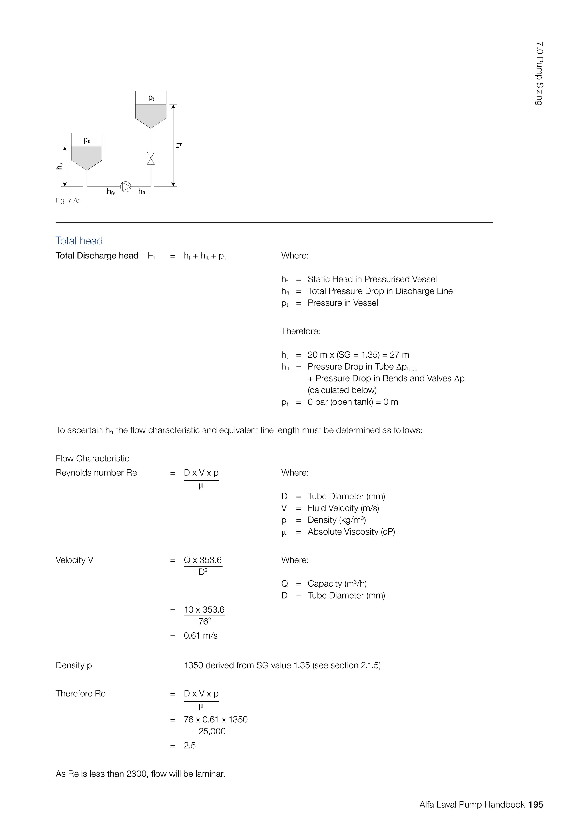
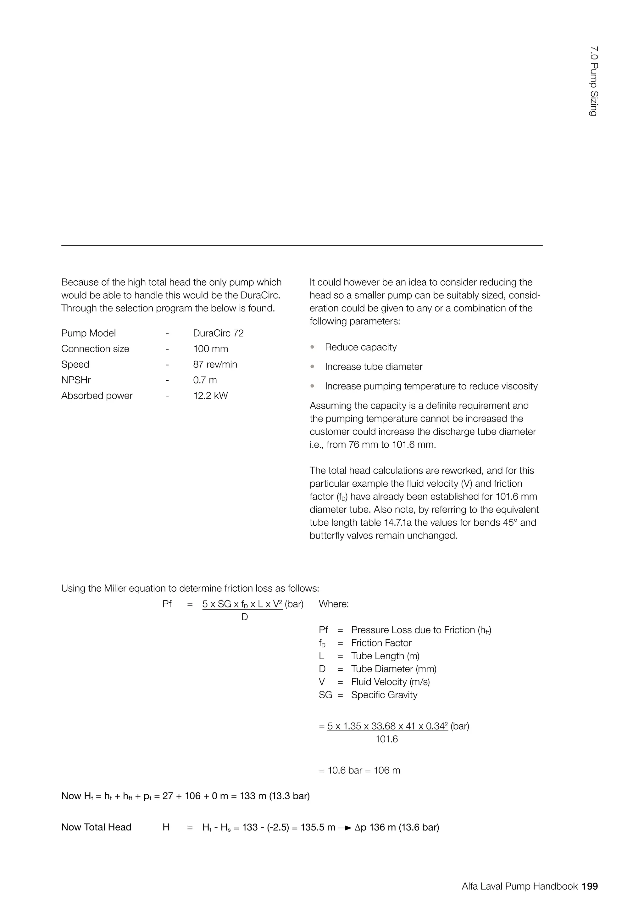
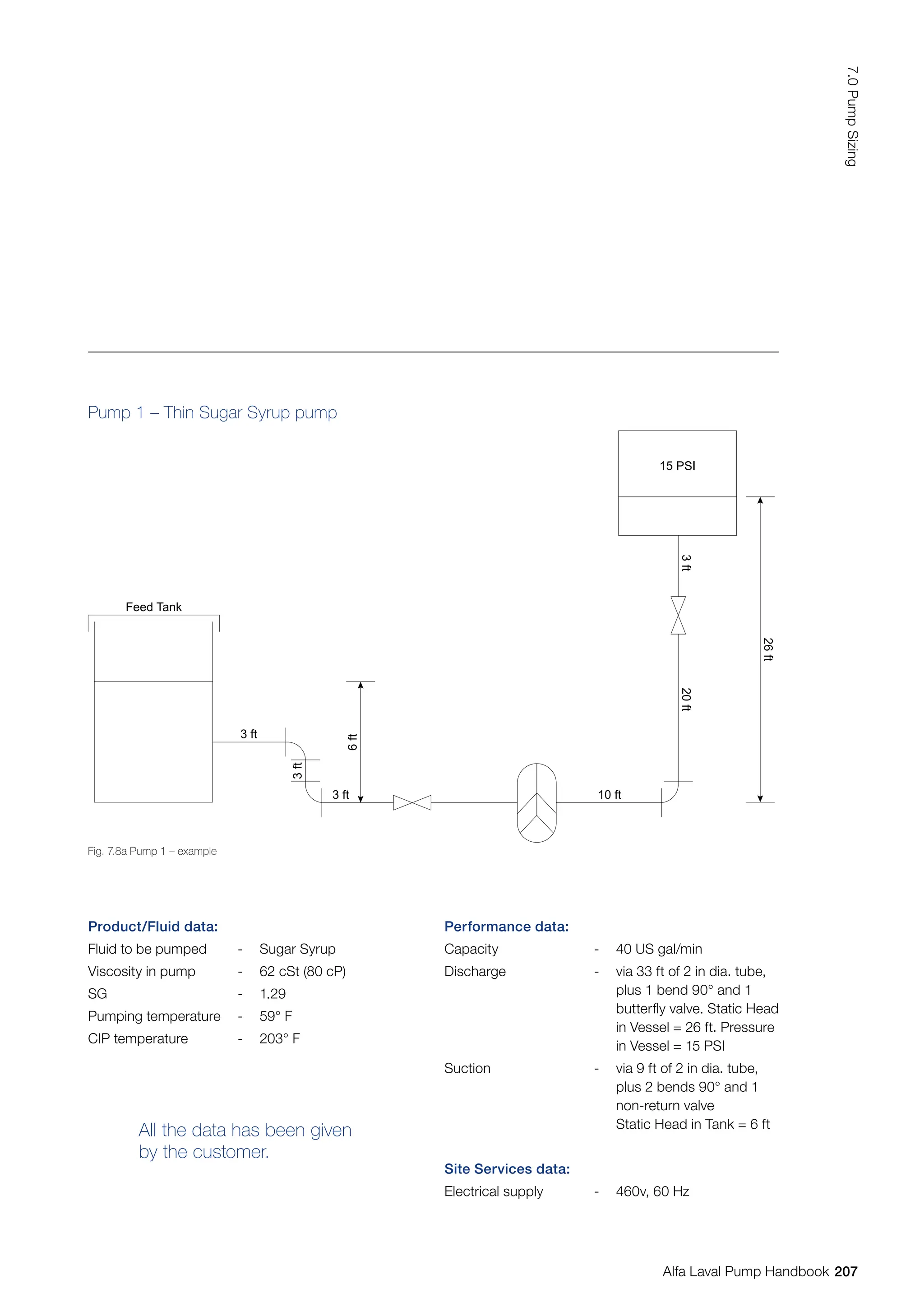
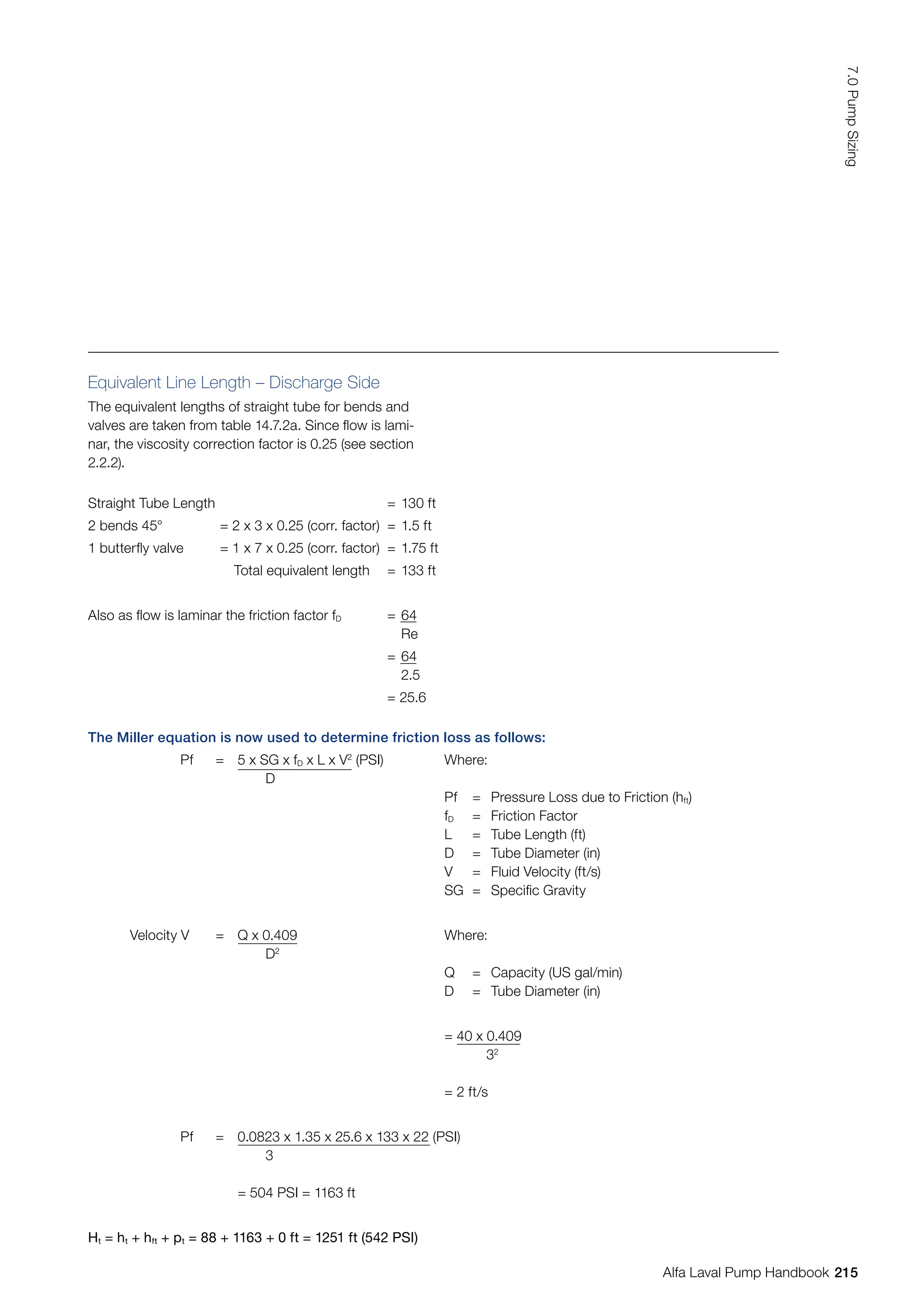
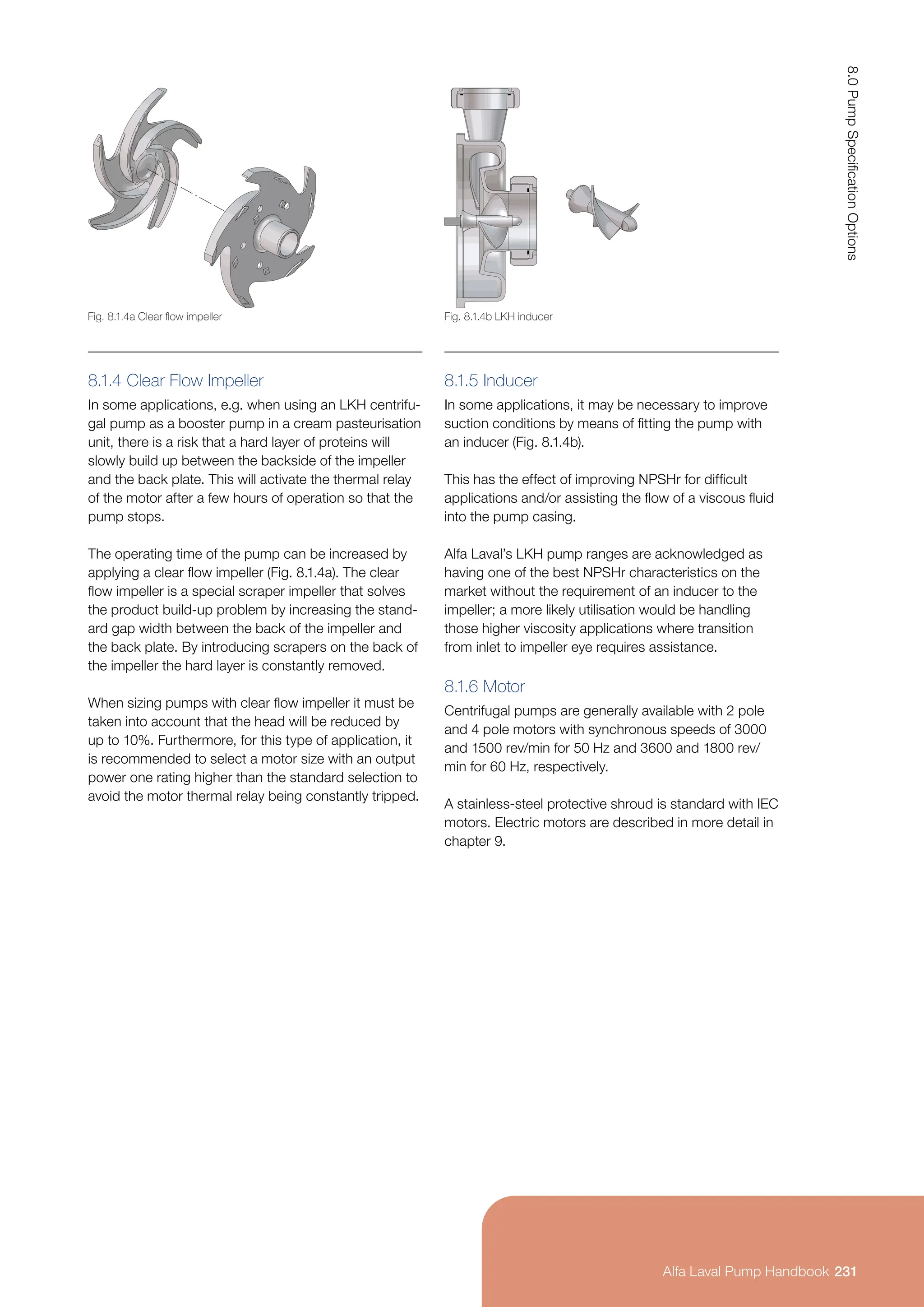
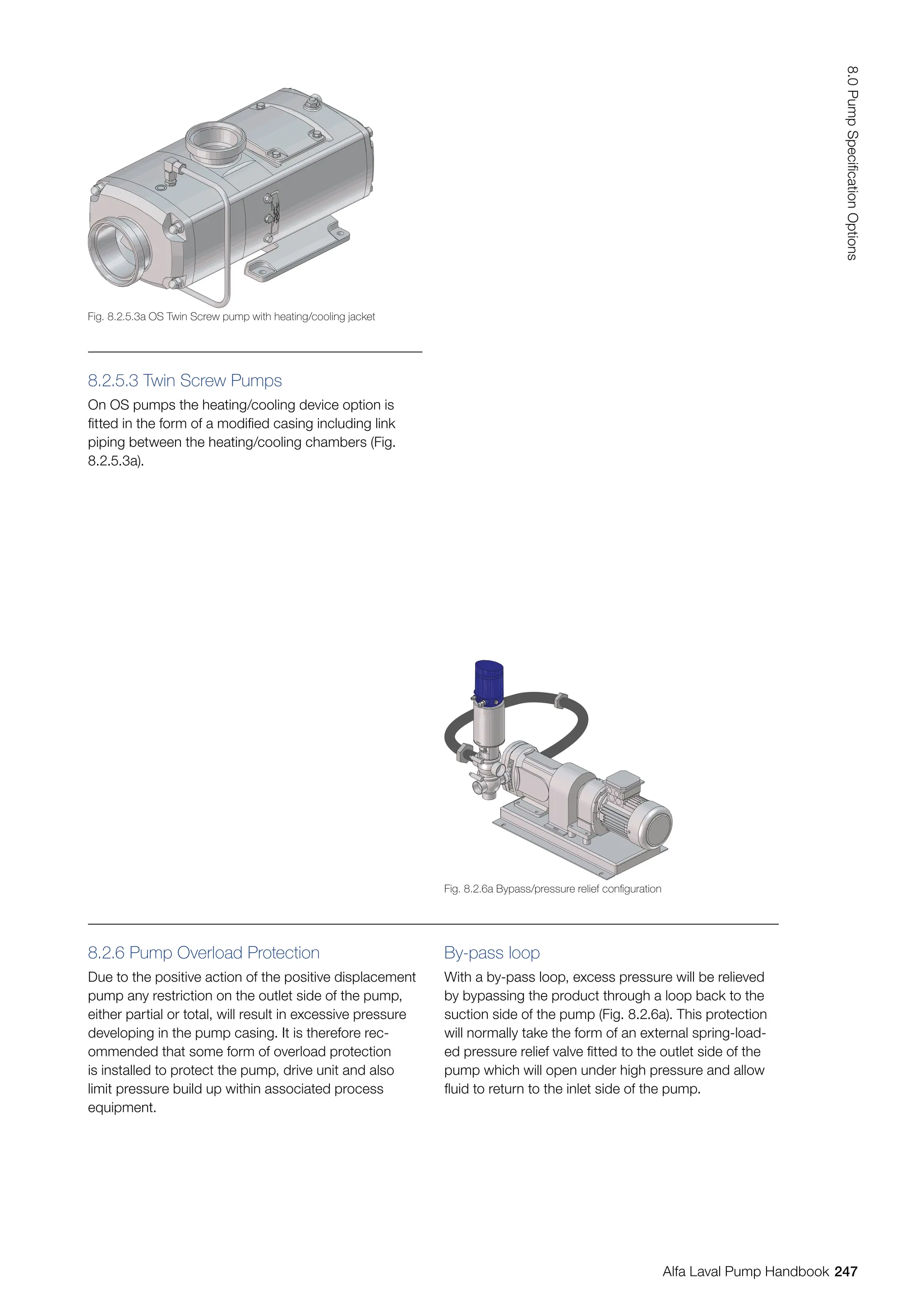
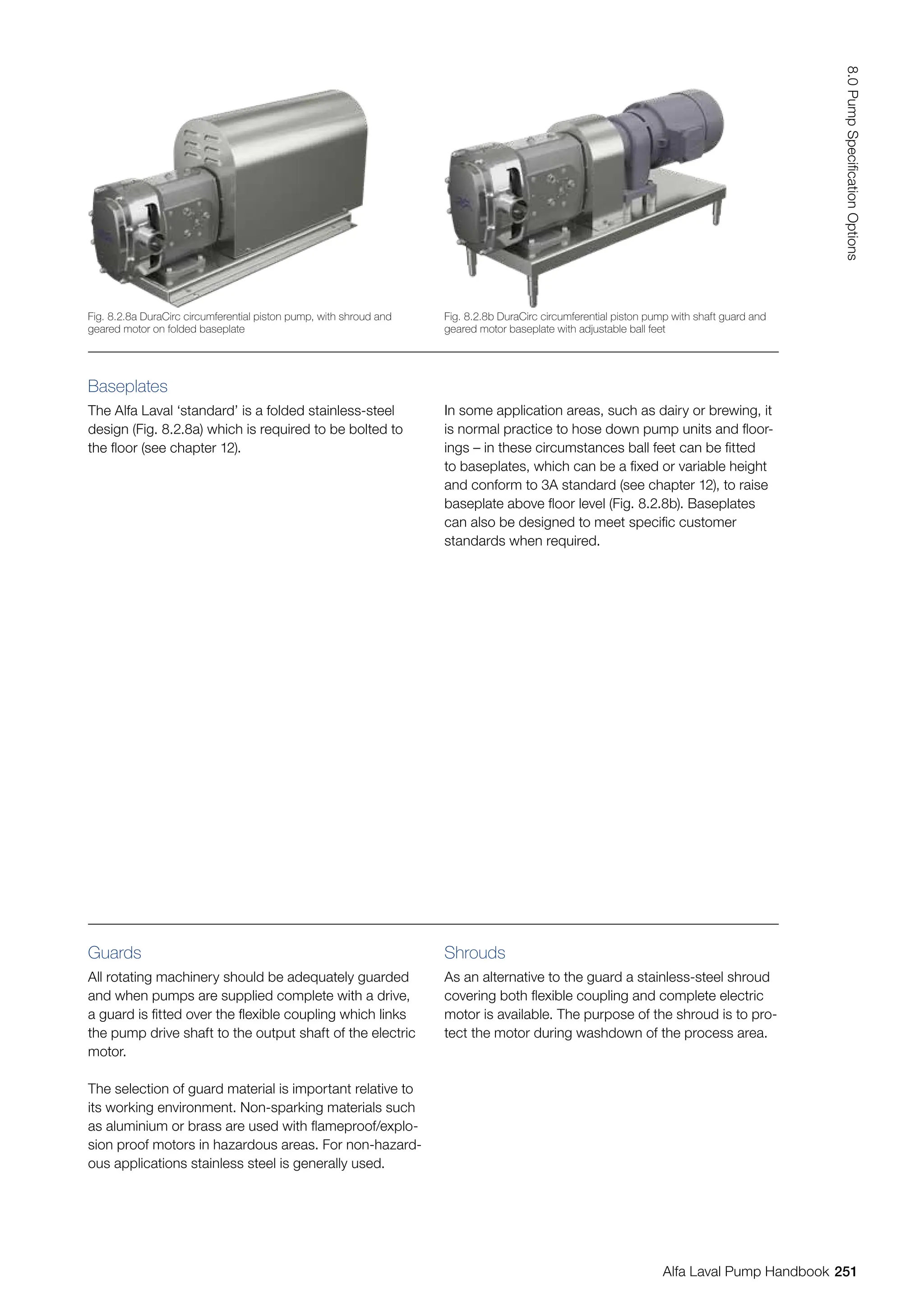
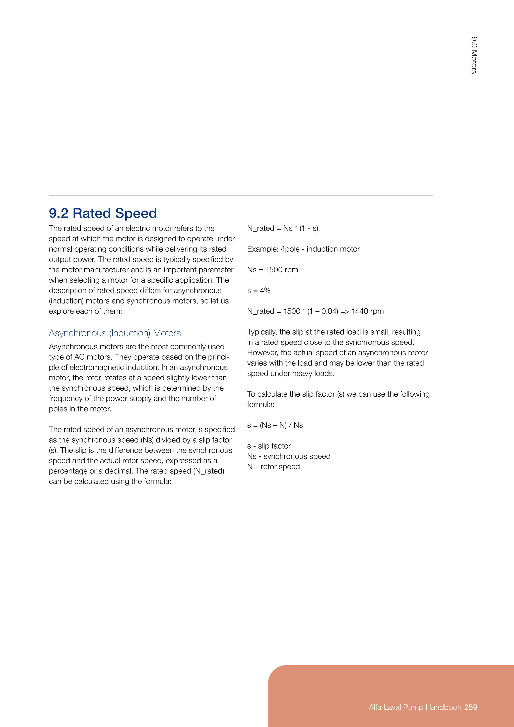
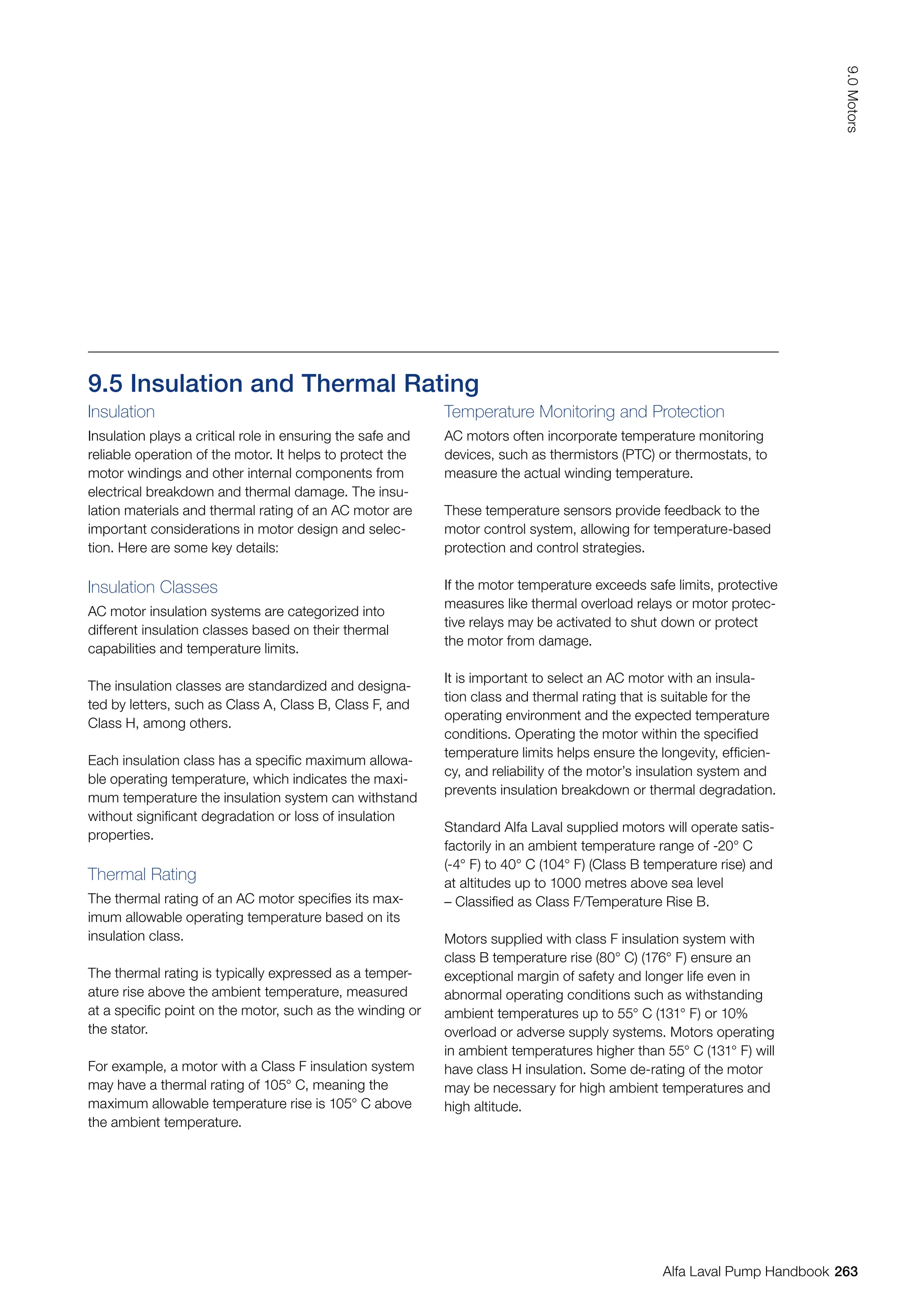
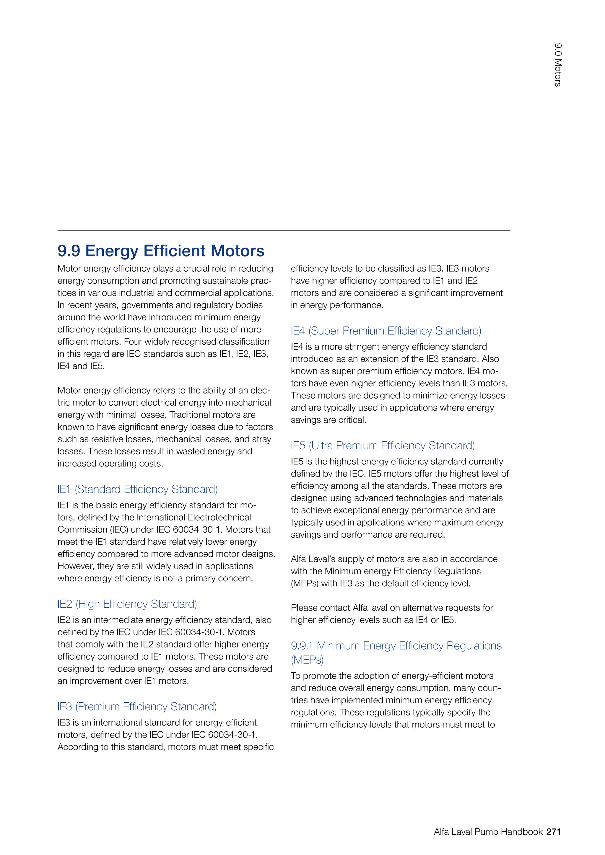
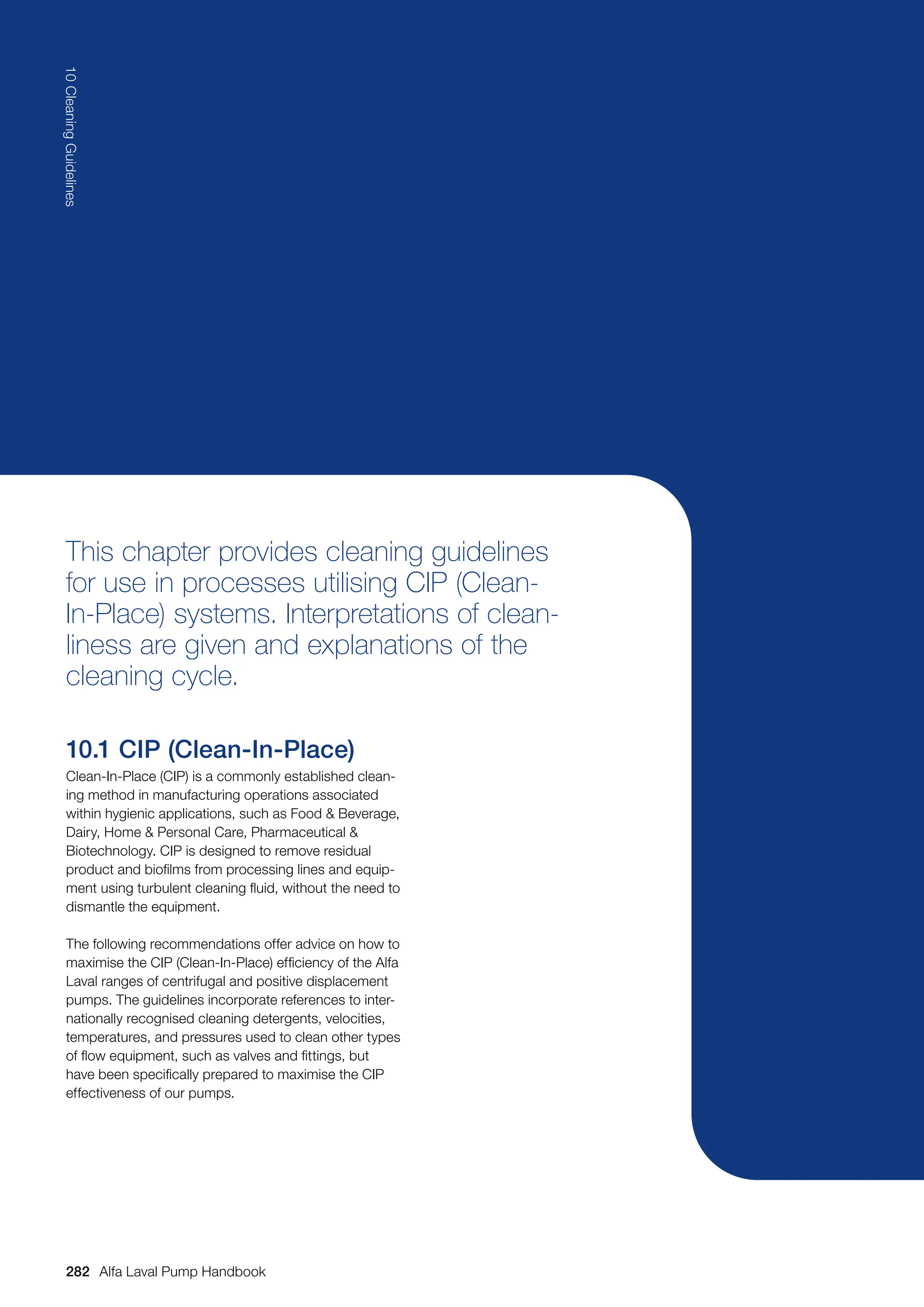
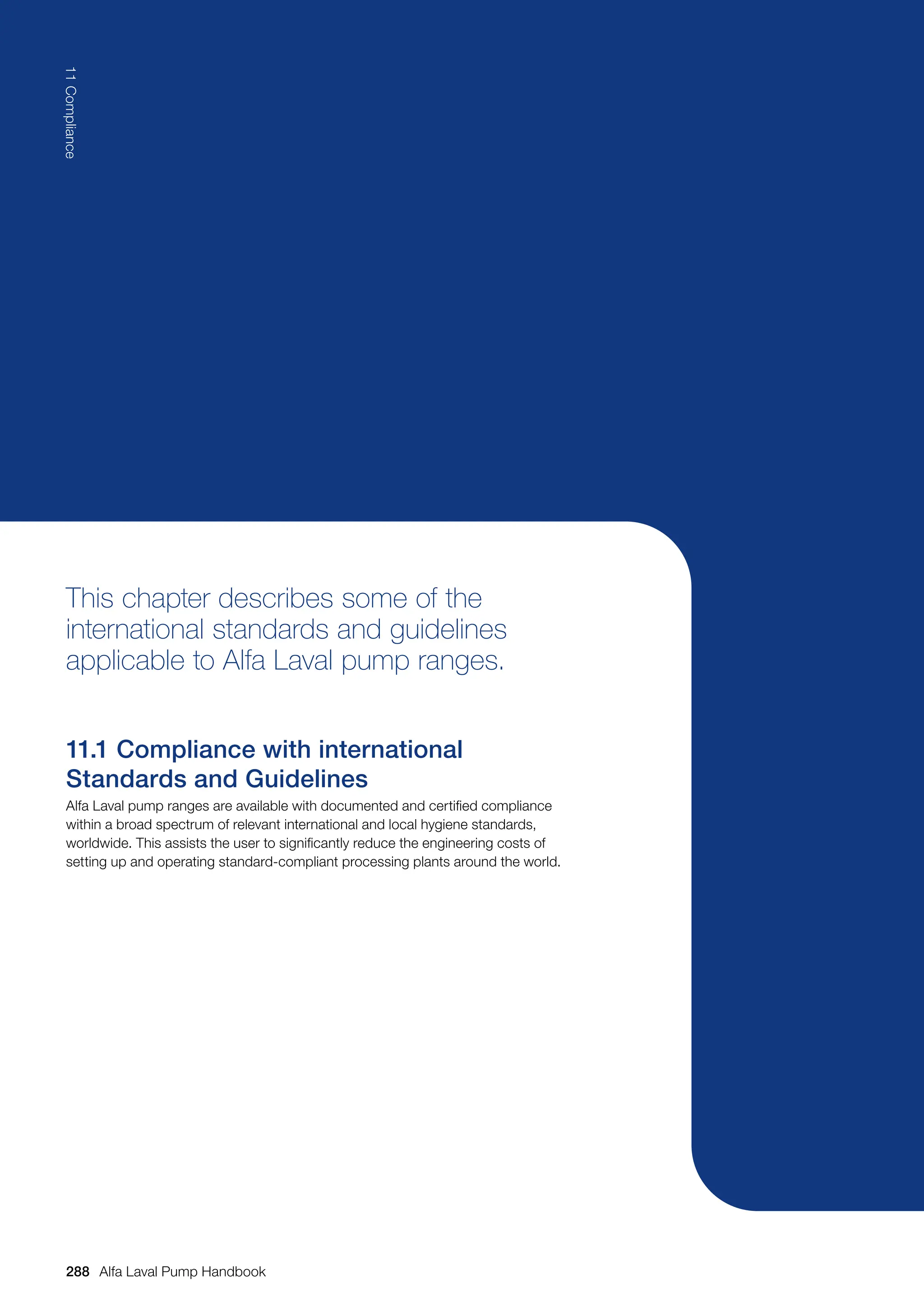
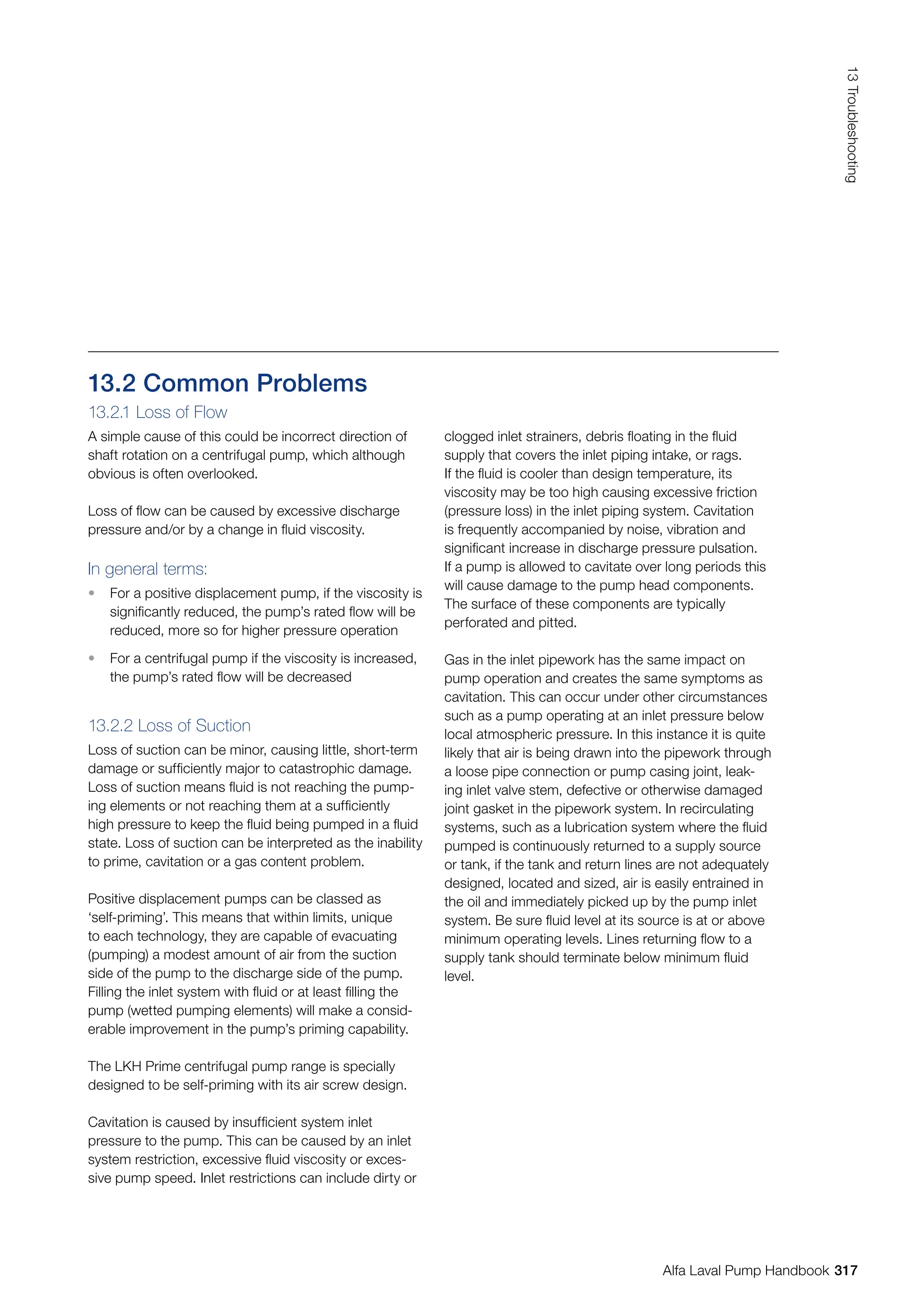
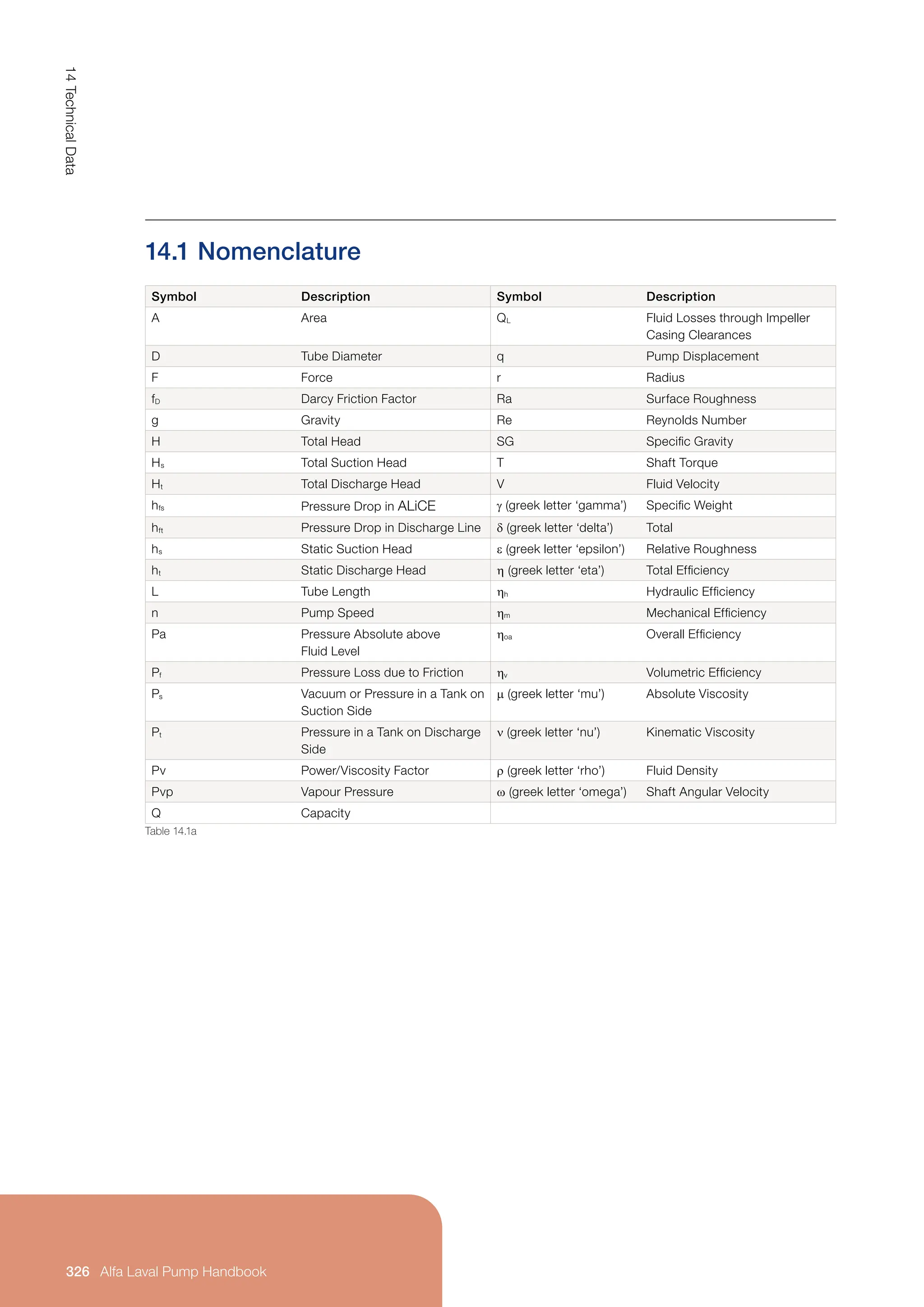
Reducing Impeller Diameter
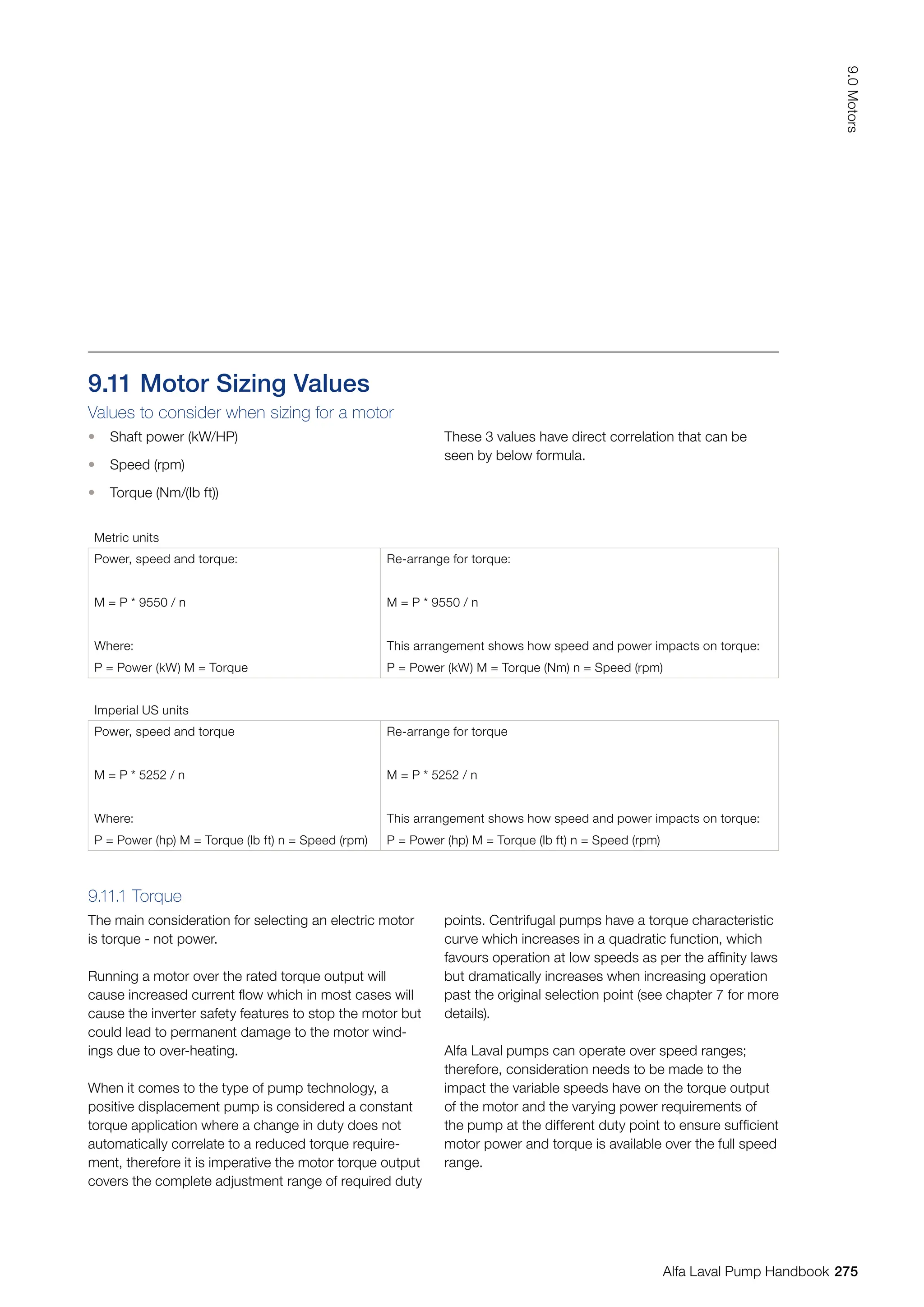
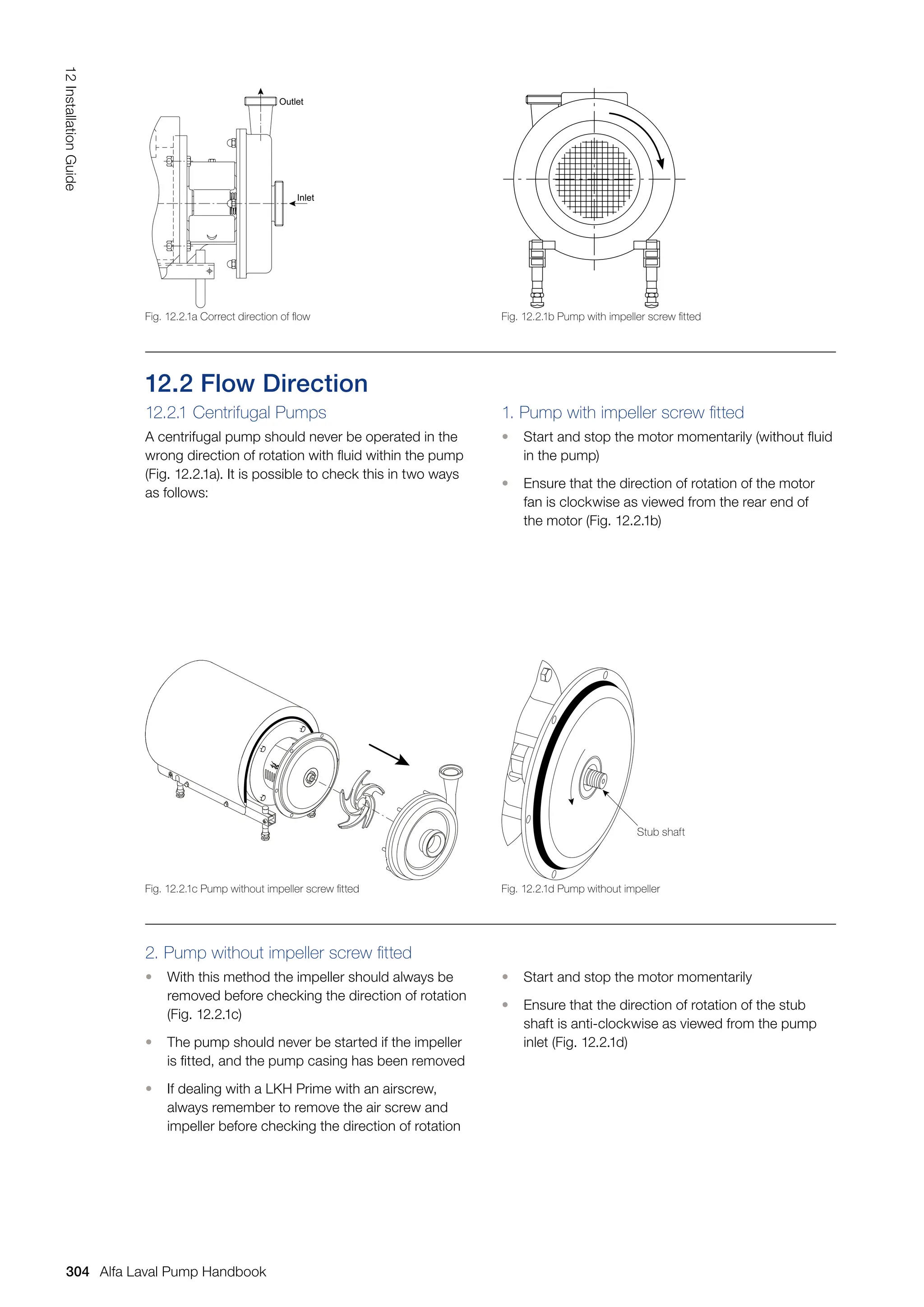
Reducing the impeller diameter can only be carried
out for centrifugal pumps. This will reduce the capacity
and the head.
Centrifugal Pump
The connection between Impeller Diameter (D),
Capacity (Q) and Head (H) is shown in Fig. 7.3.2d:
1. Before reducing
2. After reducing – the duty point moves towards point
2 when reducing the impeller diameter
If the impeller speed remains unchanged, the connec-
tion between Impeller Diameter (D), Capacity (Q), Head
(H) and Required Power (P) is shown by the following
formulas: The formula is for guidance purpos-
es only. It is recommended to add a
safety factor of 10–15% to the new
diameter.
Most pump flow curves show characteristics for
different impeller diameters to enable the correct
impeller diameter to be selected.
Reducing the impeller diameter by up to 20% will not
affect the efficiency of the pump much. If the reduction
in impeller diameter exceeds 20%, the pump efficiency
will decrease.
The impeller diameter is reduced to D2 by means of
the following formula:
D2 = D1 x [mm]
Where:
D1 = Standard Diameter before Reducing
a = Maximum Duty Point
b = Minimum Duty Point
c = Required Duty Point
Fig. 7.3.2d Reducing impeller diameter
H
2
1
D1
D2
Q1
Q2
H2
H1
Q
131
7.0
Pump
Sizing
Alfa Laval Pump Handbook](https://image.slidesharecdn.com/pump-handbook-2024-251113133245-895f754e/75/Alfa-Laval-Pump-Handbook-Second-Edition-2023-133-2048.jpg)
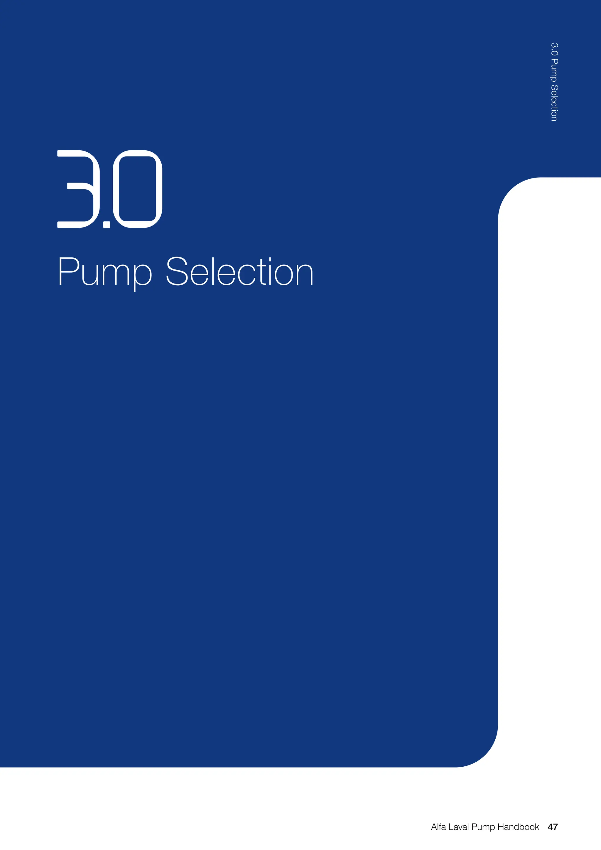
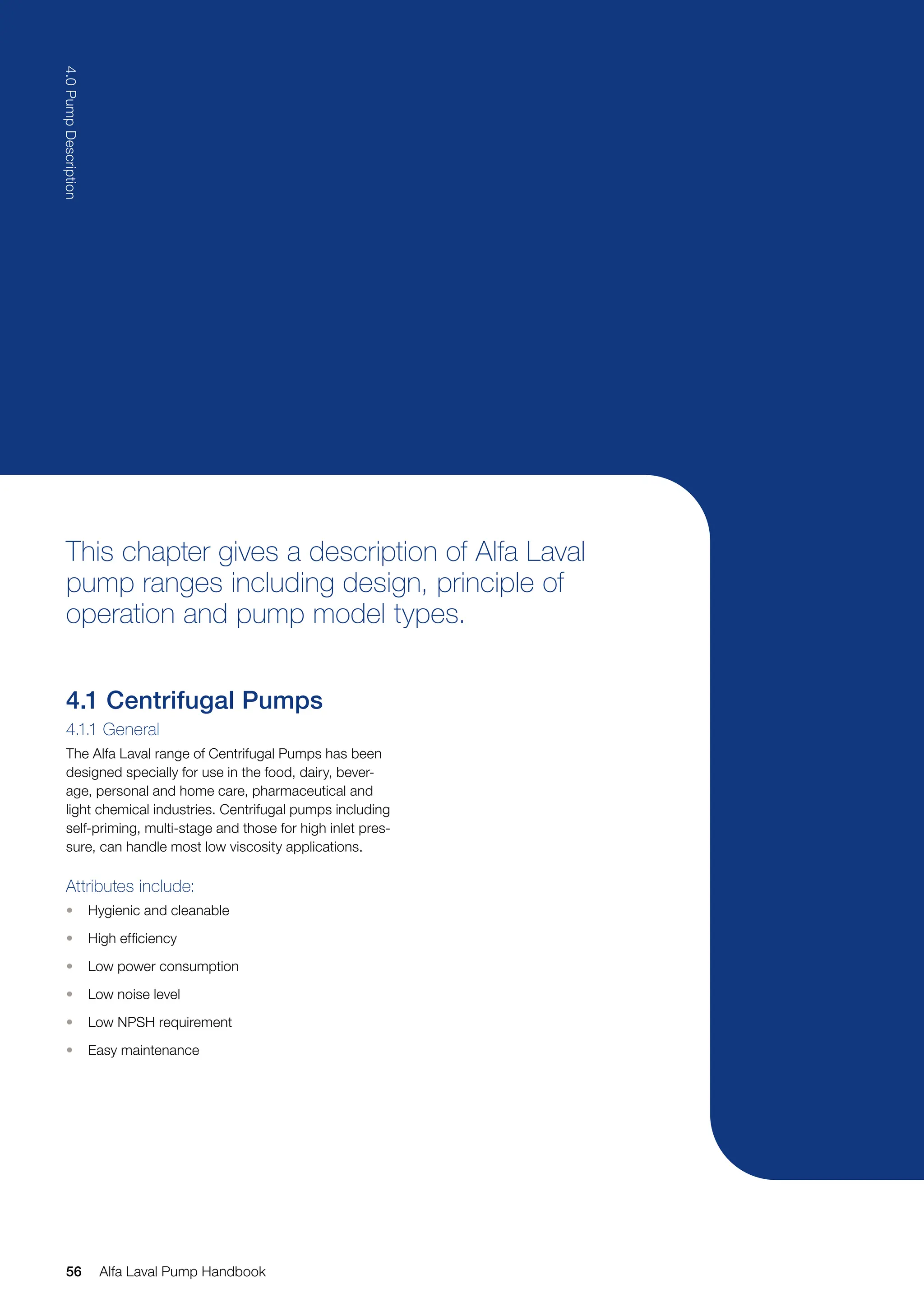
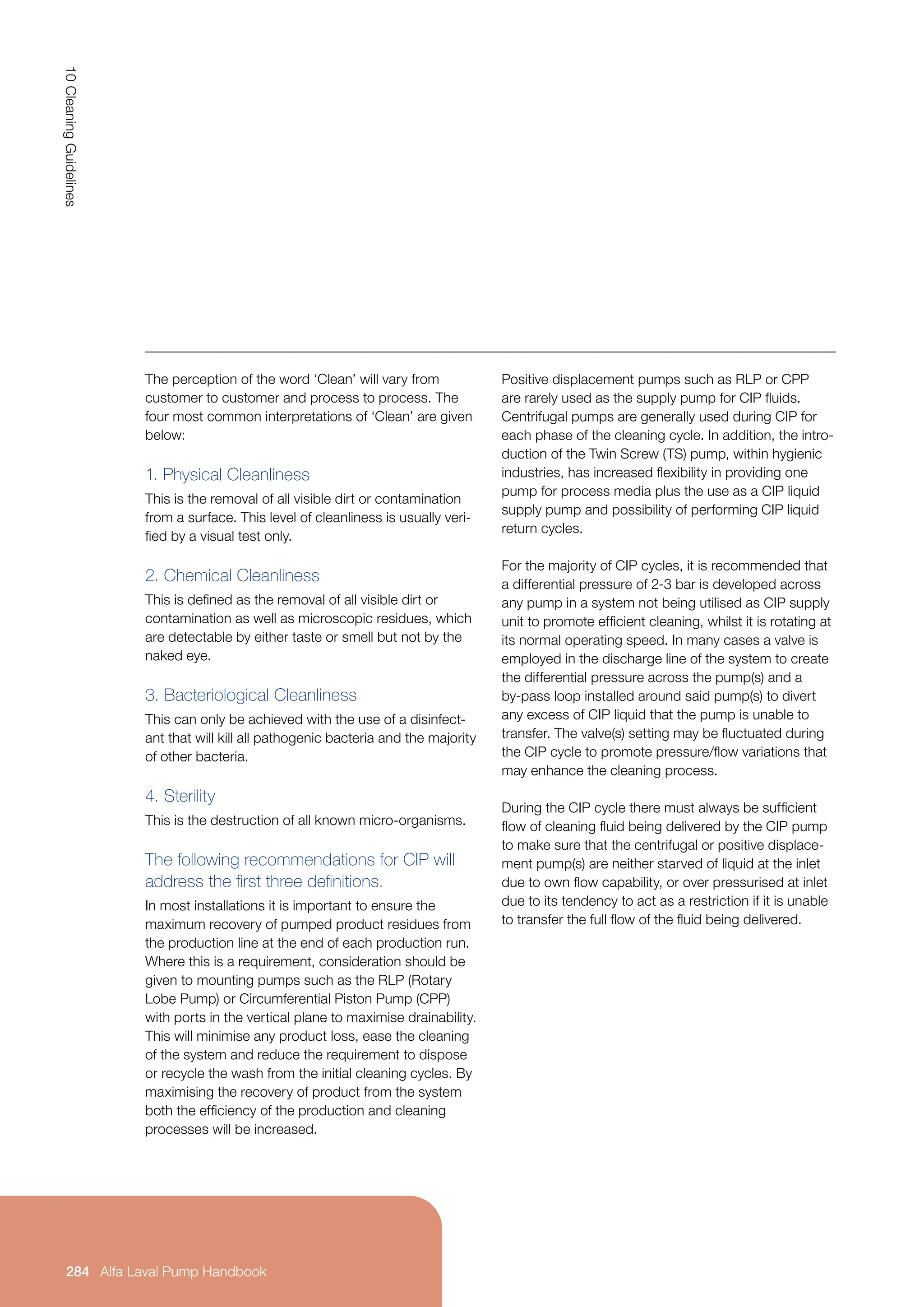
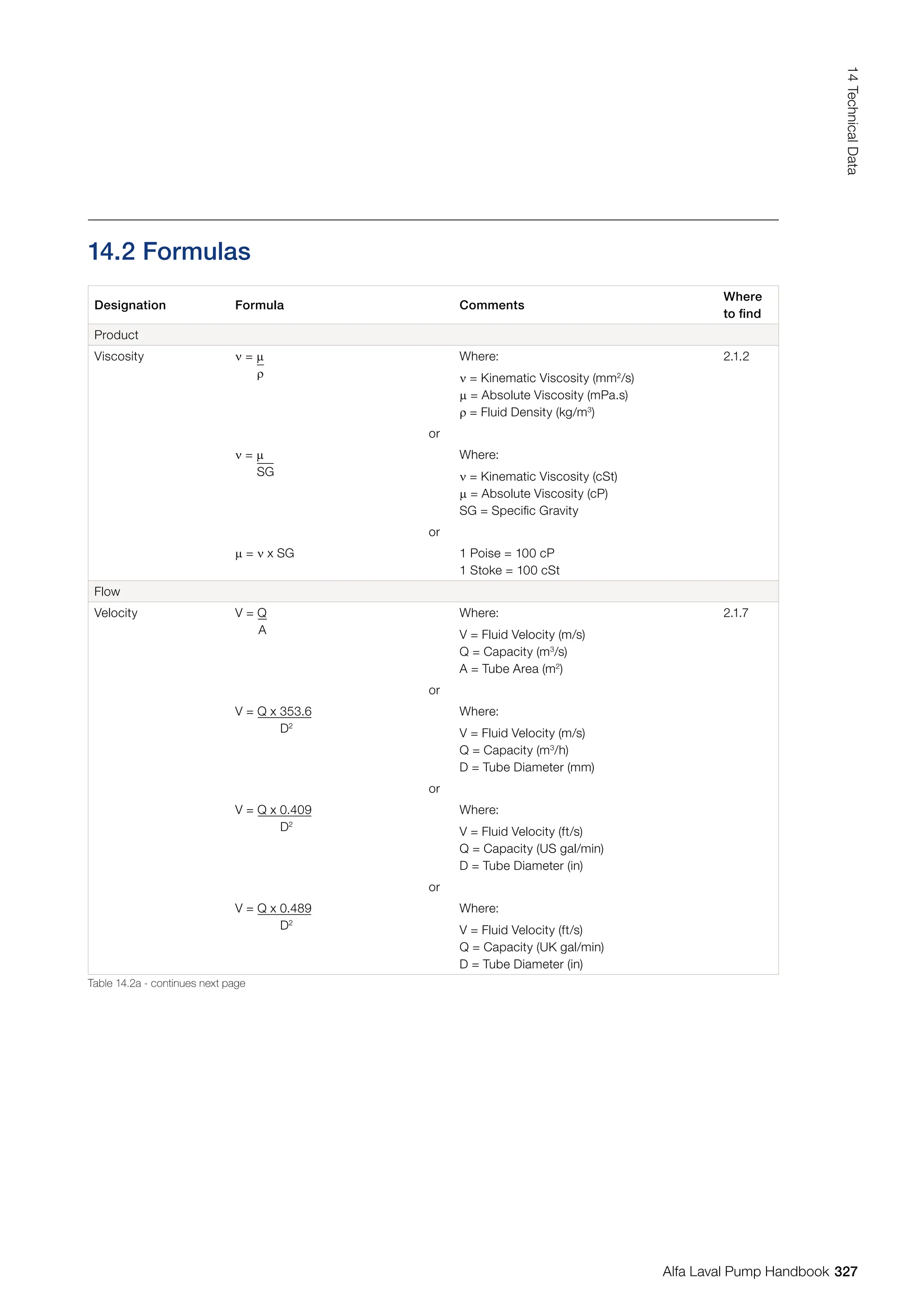
![The most common form of
speed control is by means
of a frequency converter
(see section 9.10).
Speed/Capacity: Q1 = n1 ⇒ n2 = n1 x Q2
Q2 n2 Q1
[rev/min]
Speed/Head: H1 = n1
2
⇒ n2 = n1 x
H2 n2
2
[rev/min]
Speed/Power P1 = n1
3
⇒ n2 = n1 x
P2 n2
3
[rev/min]
√
3 P2
P1
√H2
H1
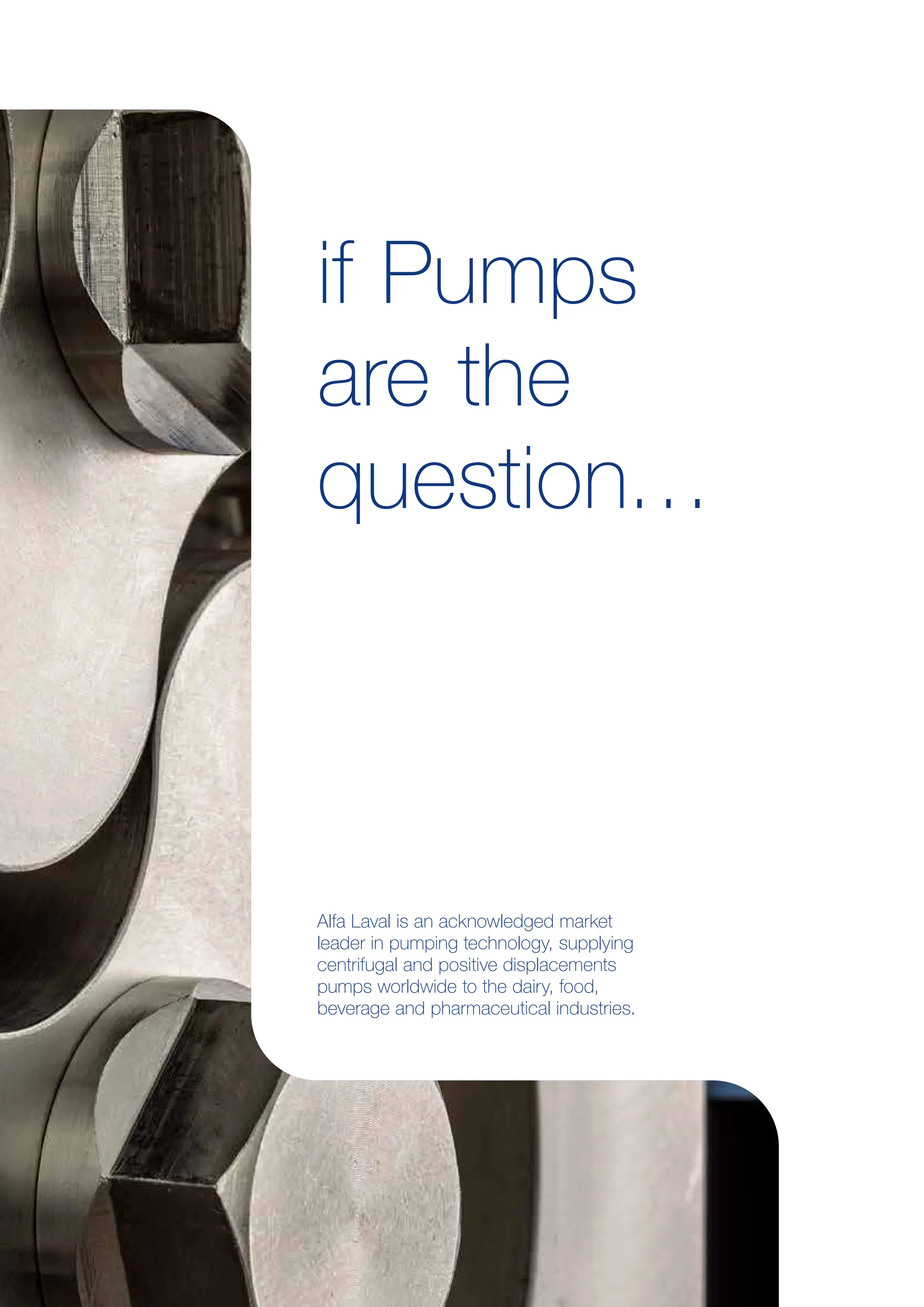
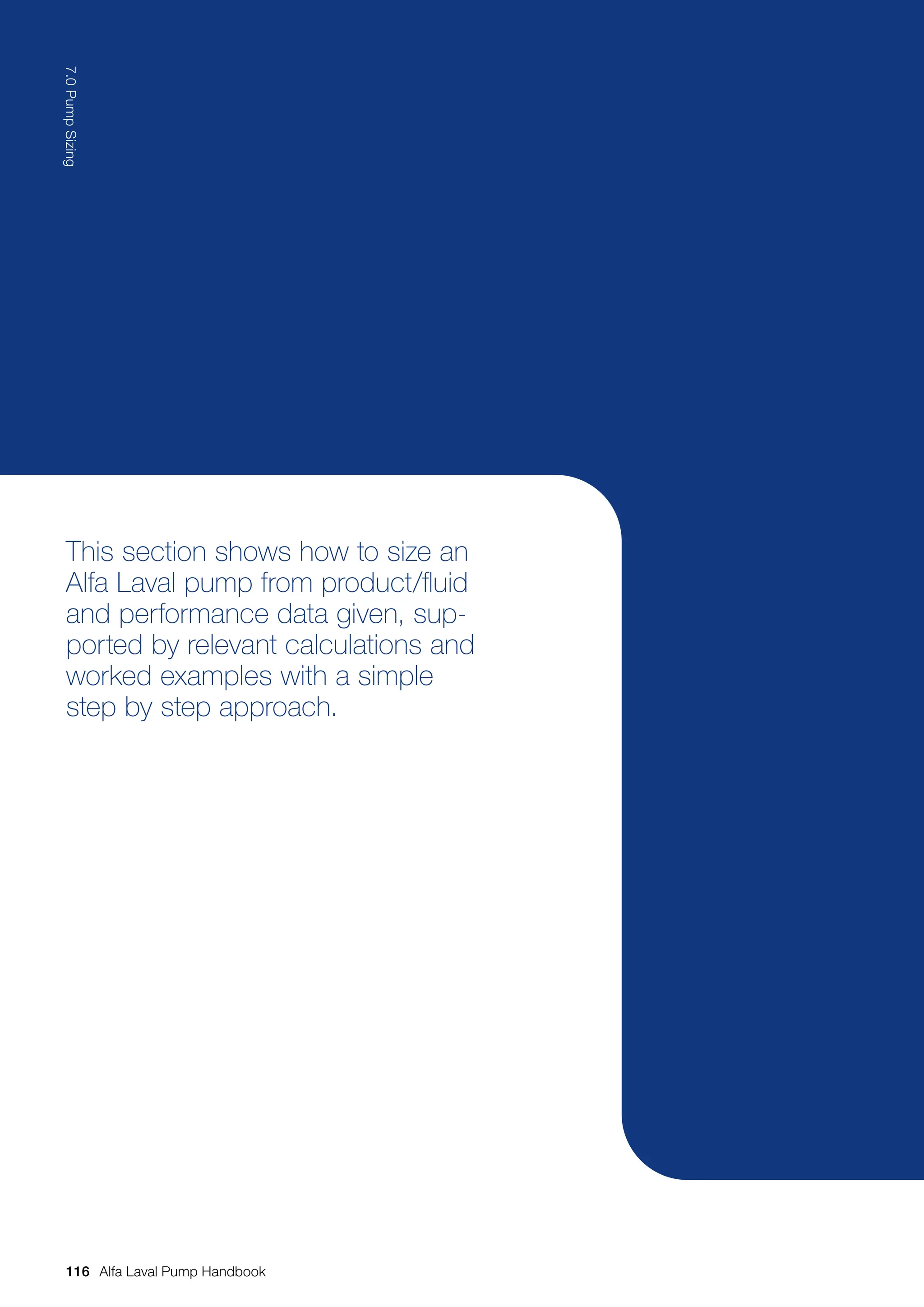
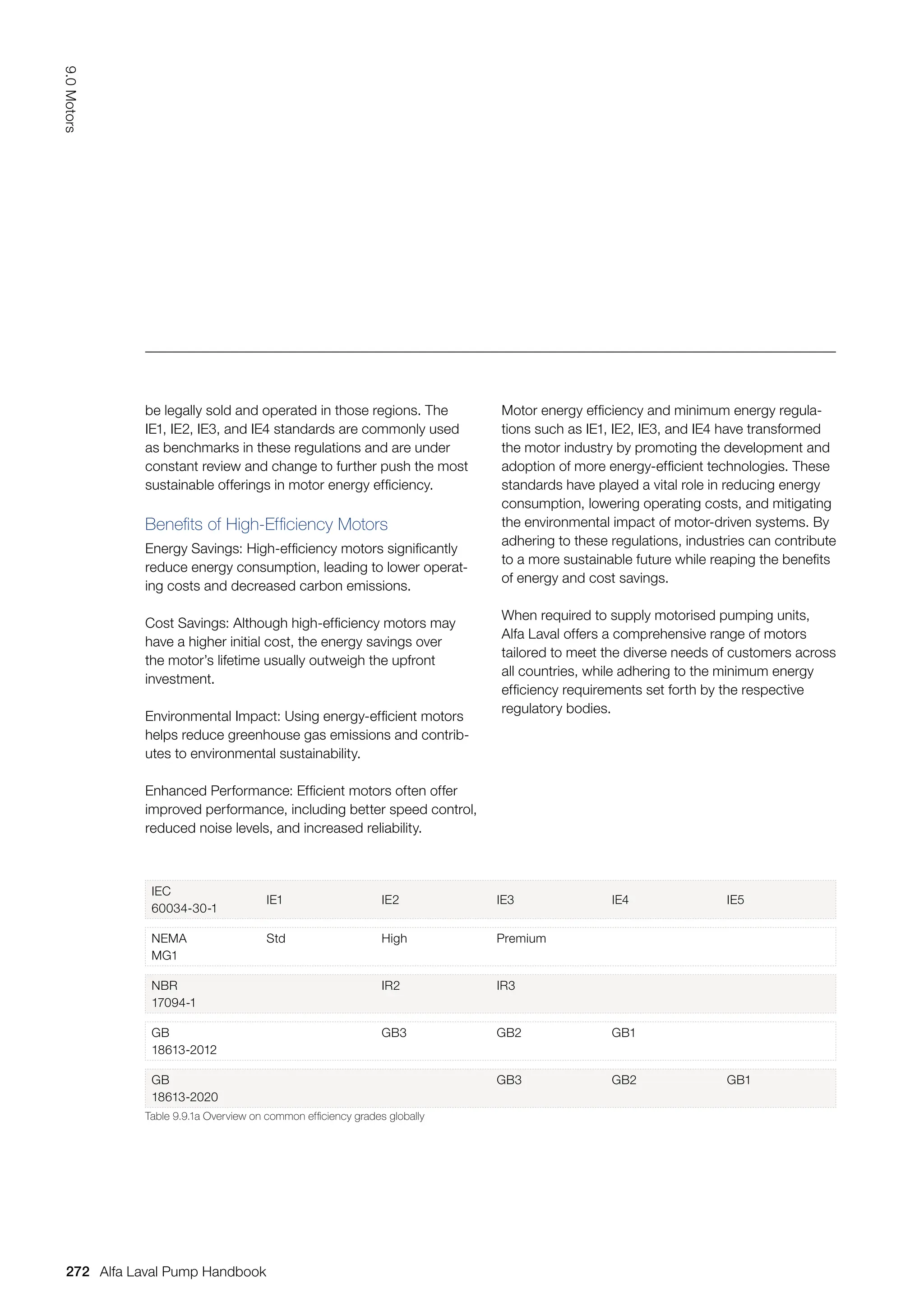
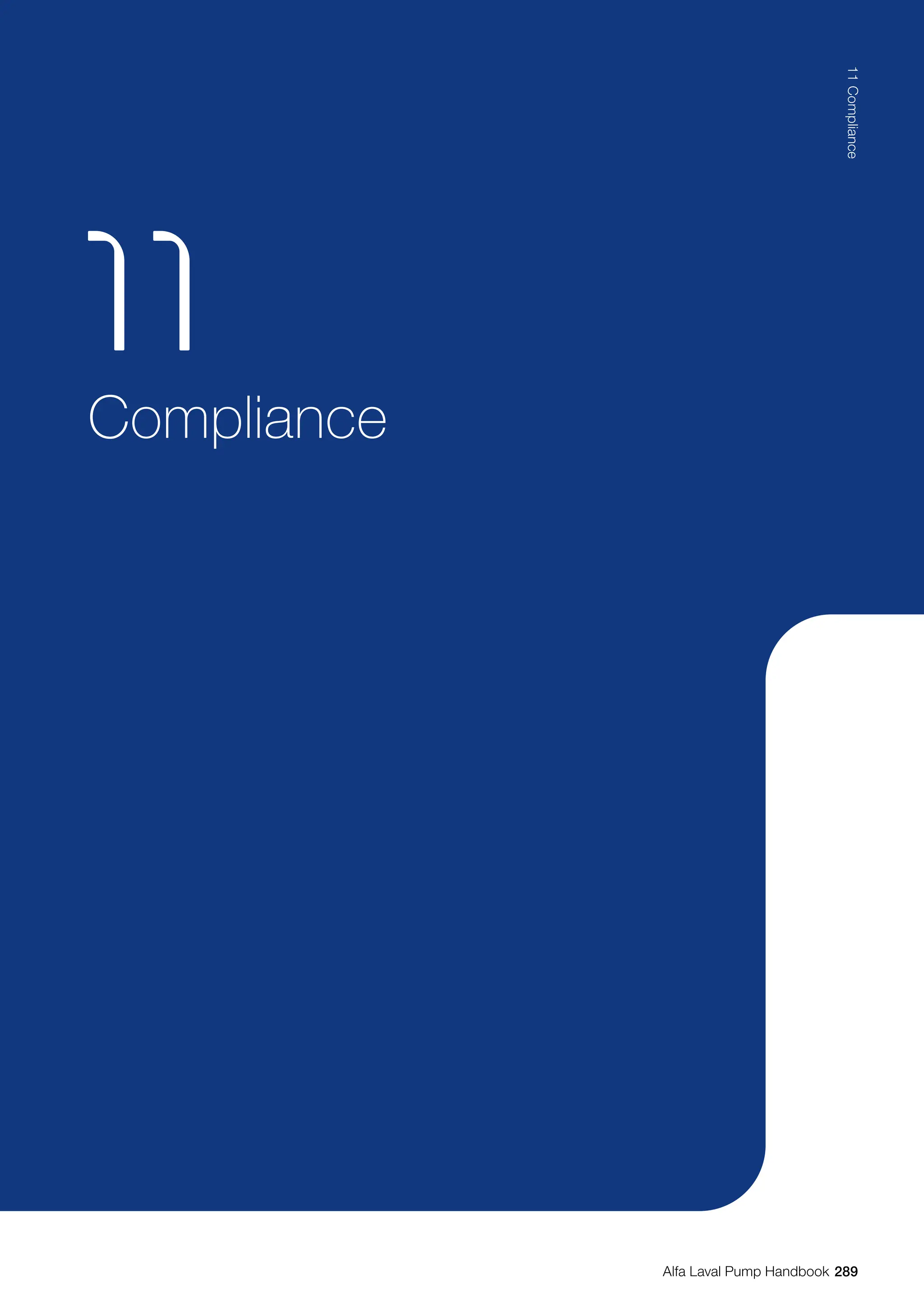
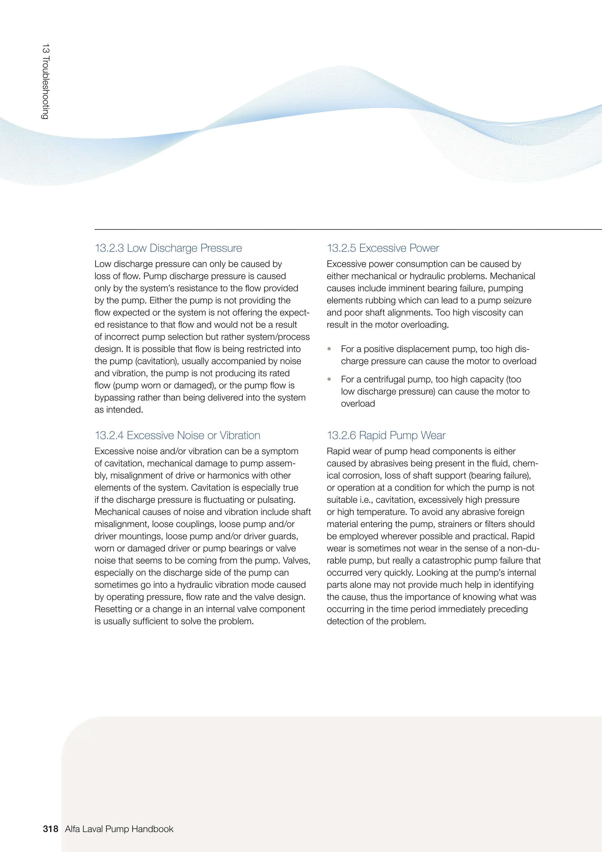
If the impeller dimensions remain unchanged, the
connection between Impeller Speed (n), Capacity (Q),
Head (H) and Required Power (P) is shown by the
following formulas:
As shown from the above formulas the impeller speed
affects capacity, head and required power as follows:
• Half speed results in capacity x 0.5
• Half speed results in head x 0.25
• Half speed results in required power x 0.125
Speed control will not affect the efficiency much
providing changes do not exceed 20%.
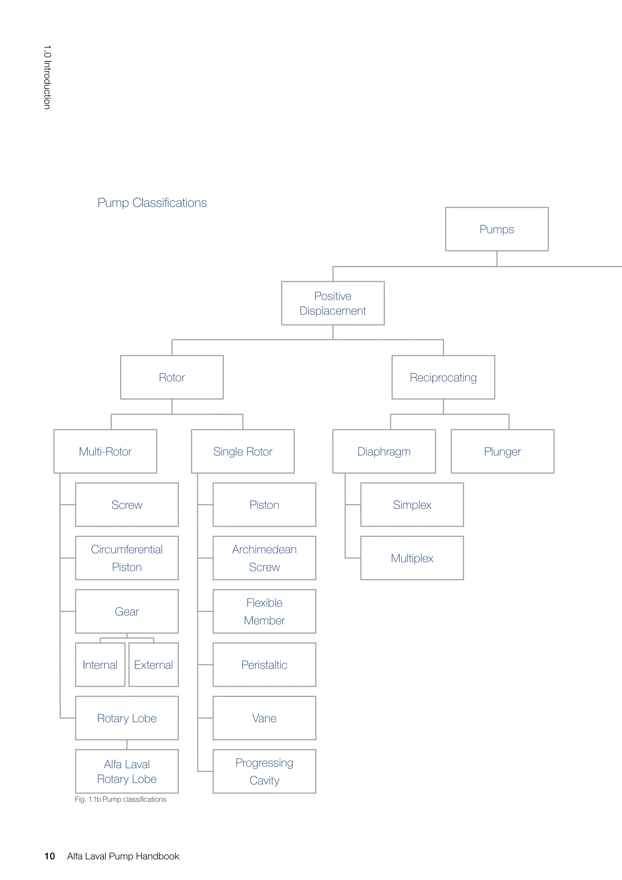
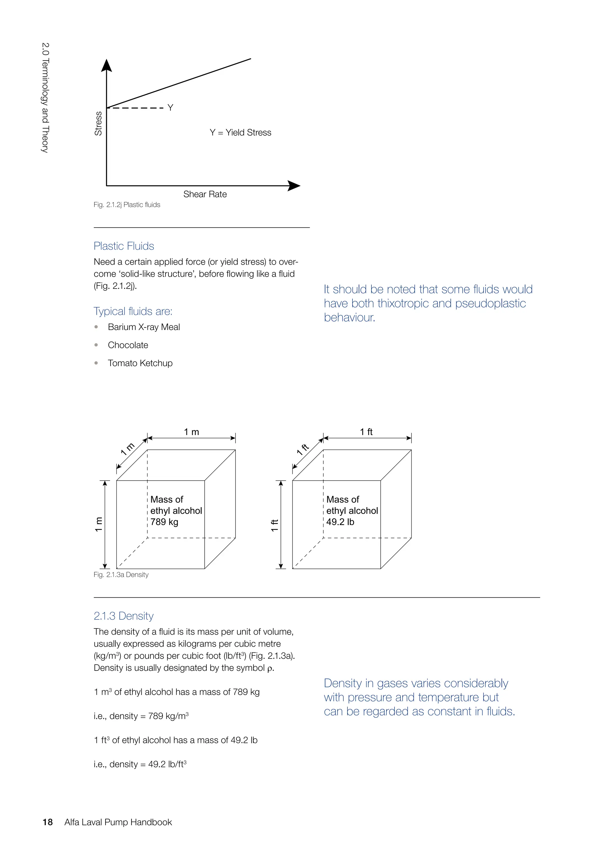
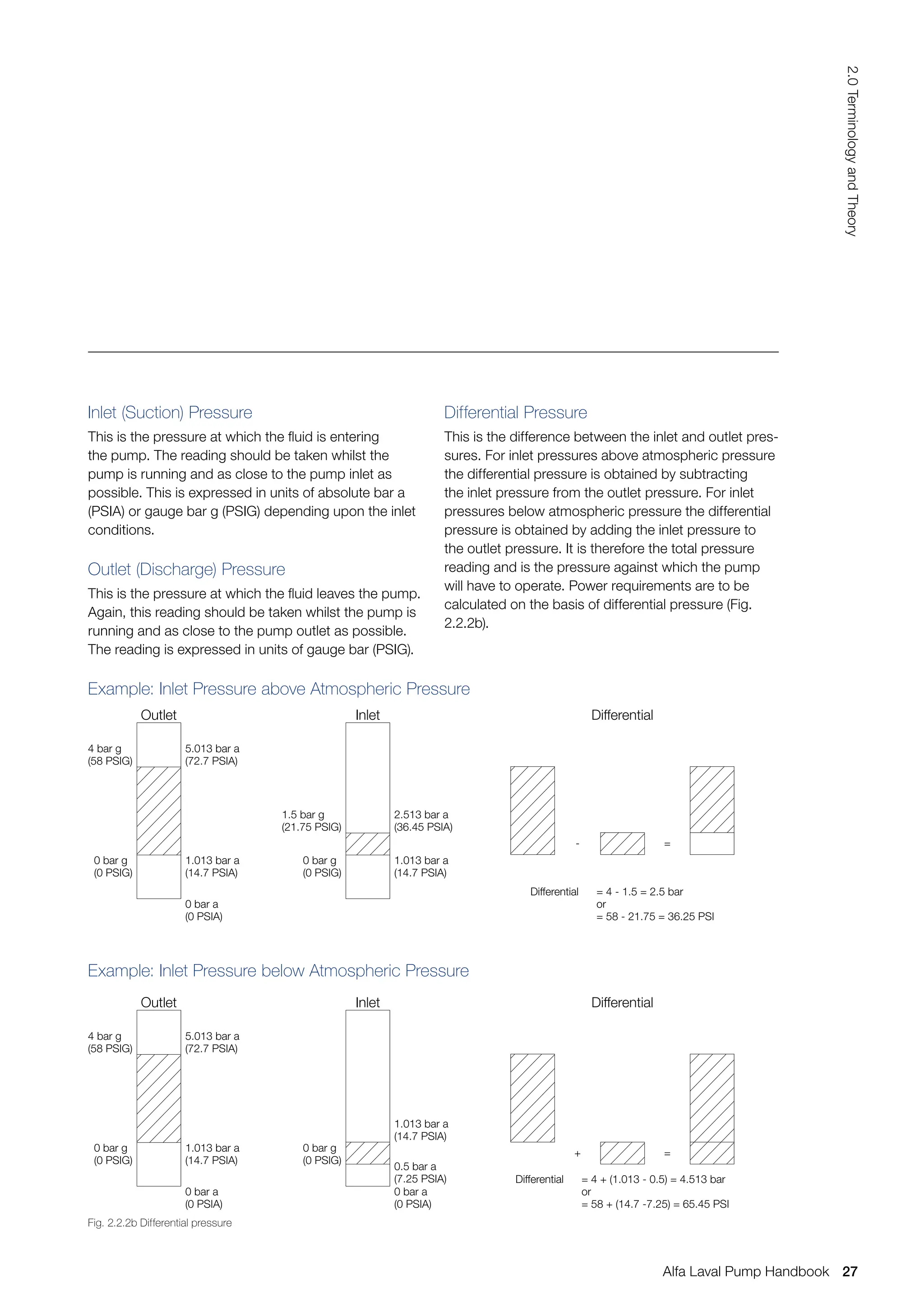
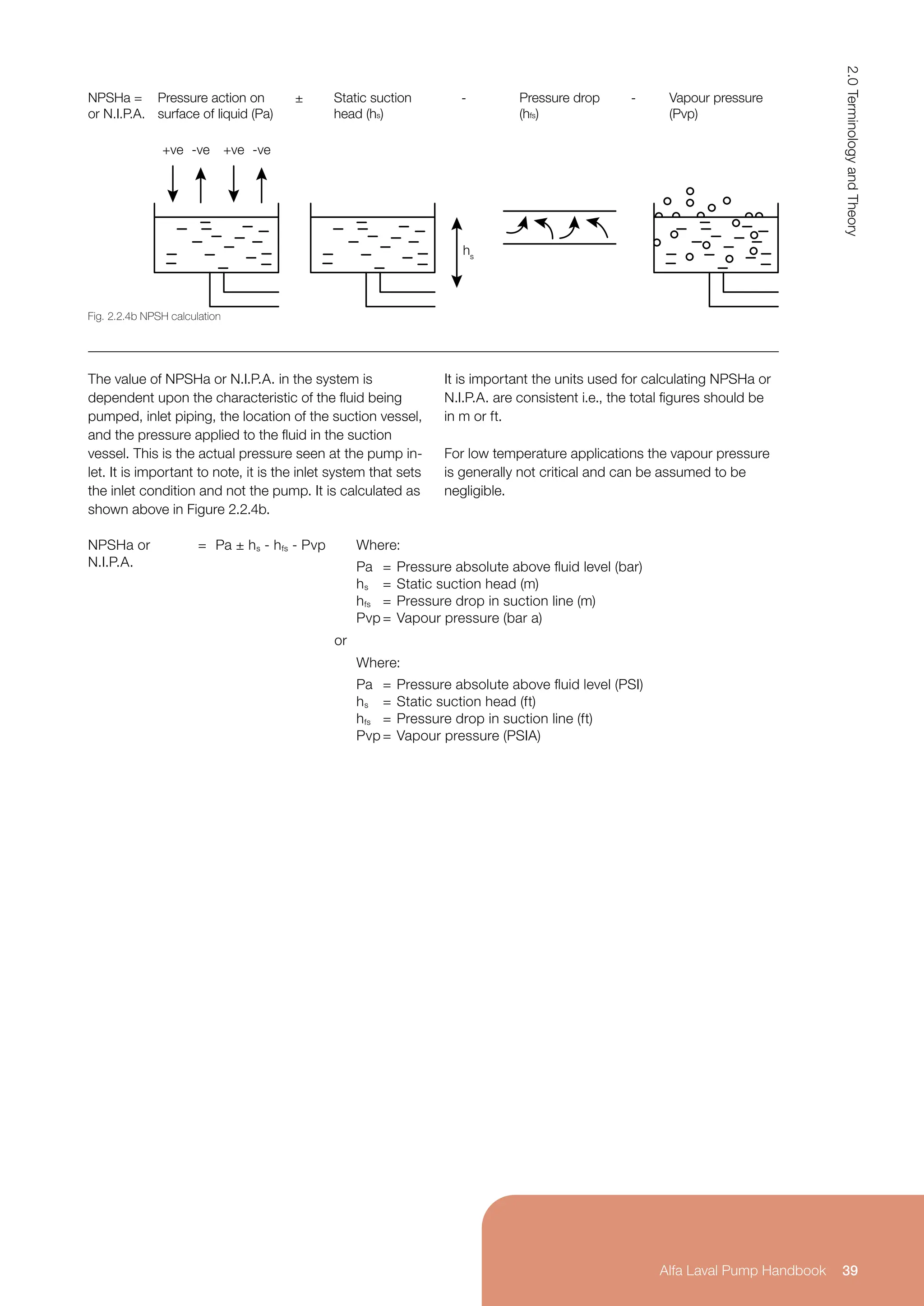
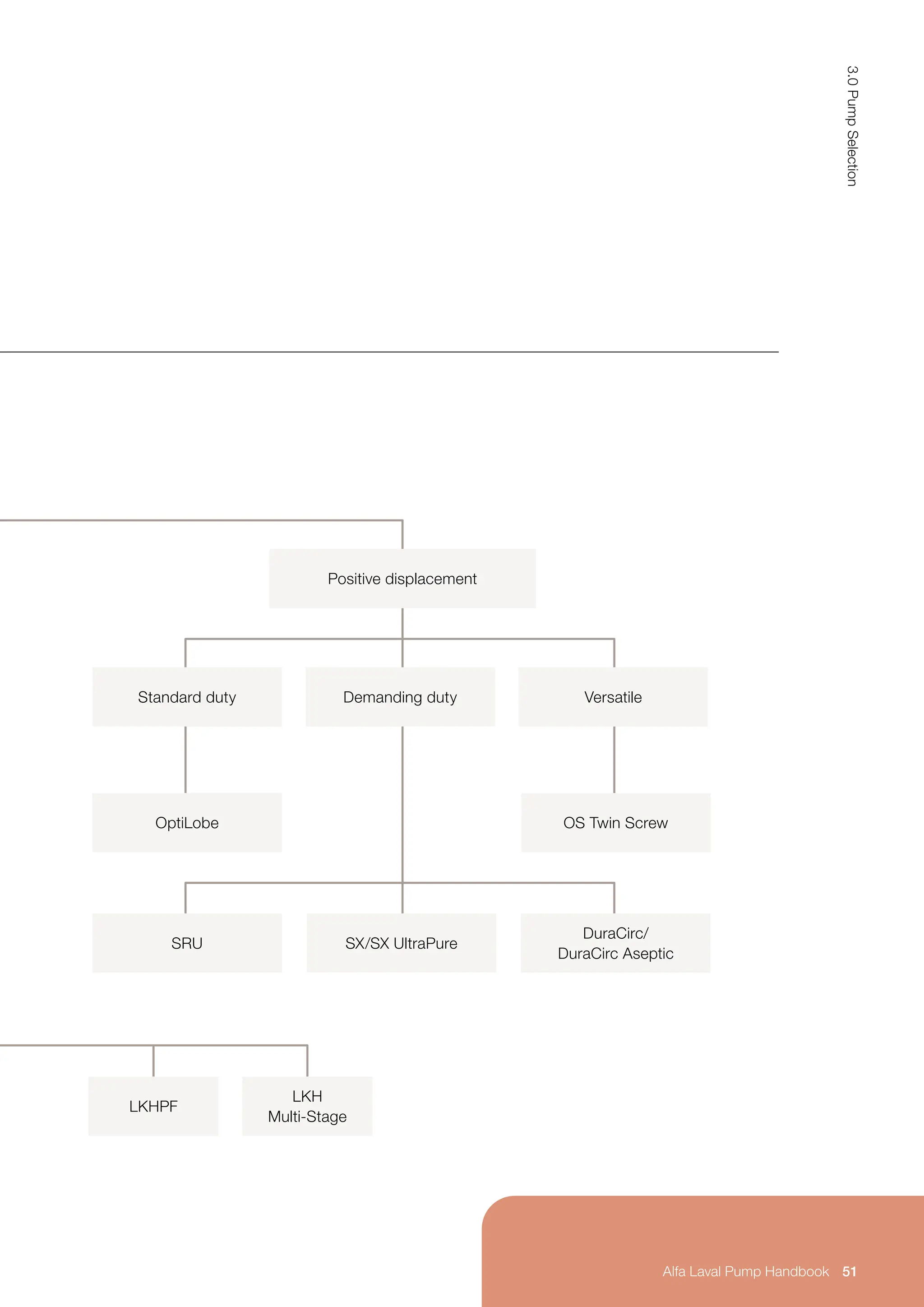
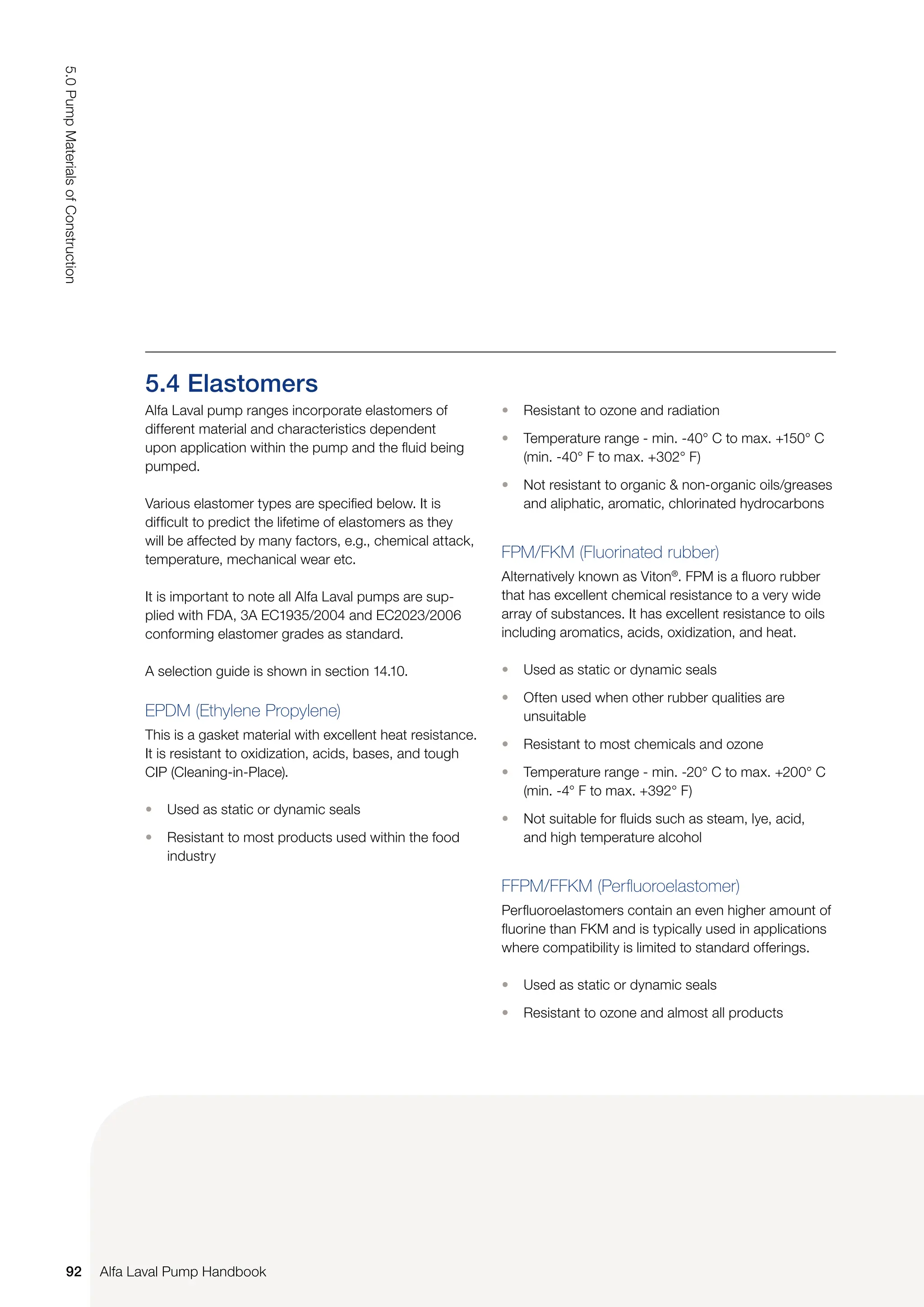
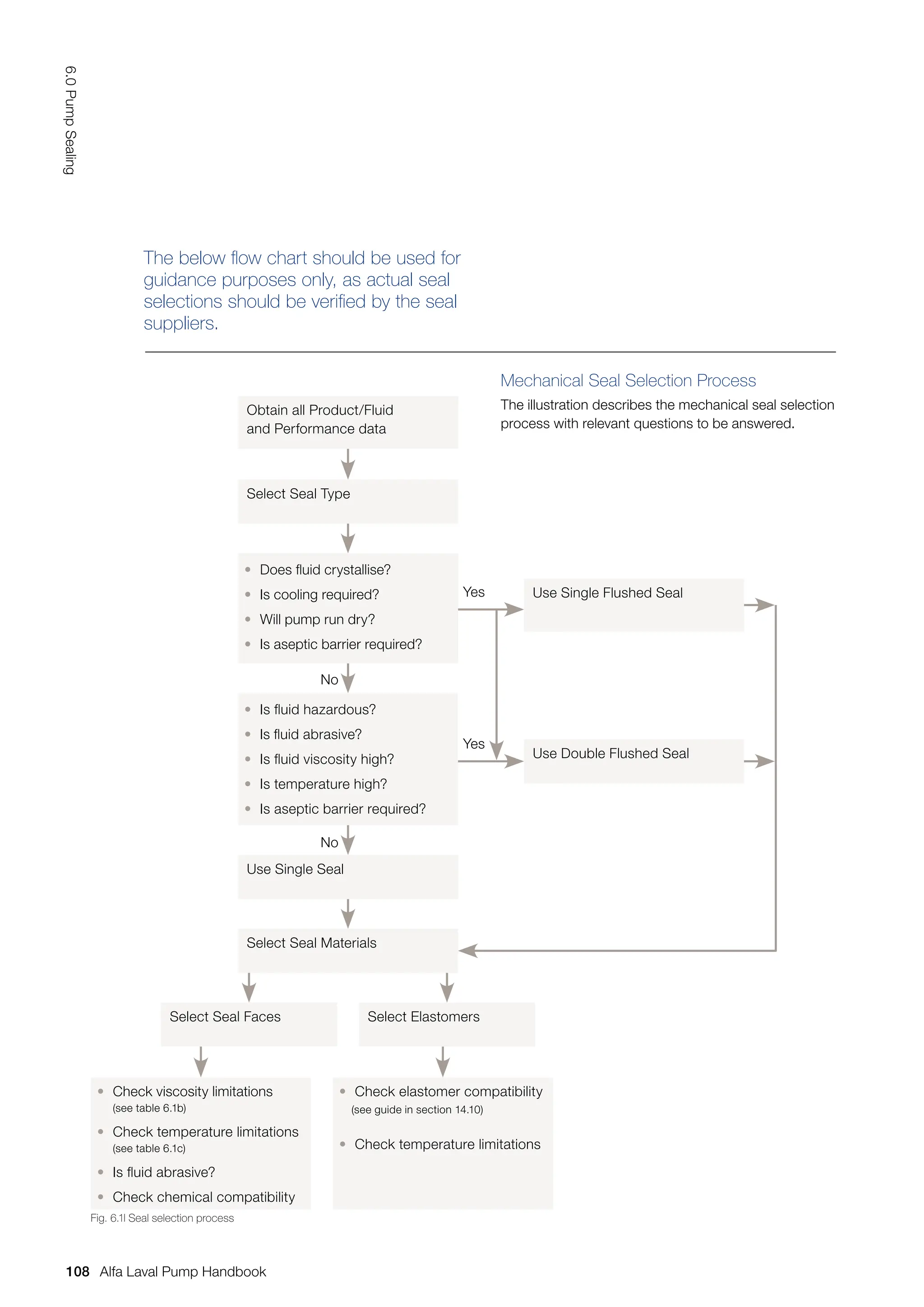
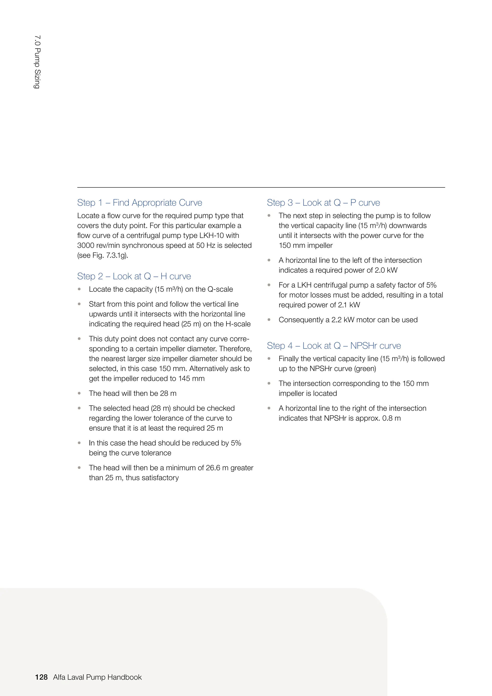
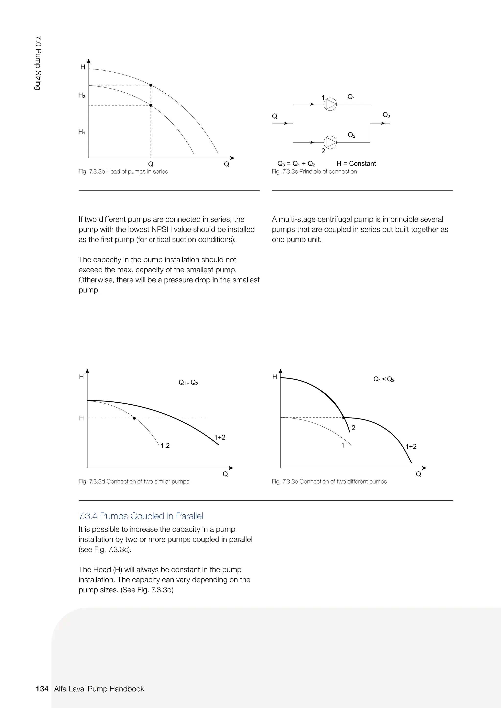
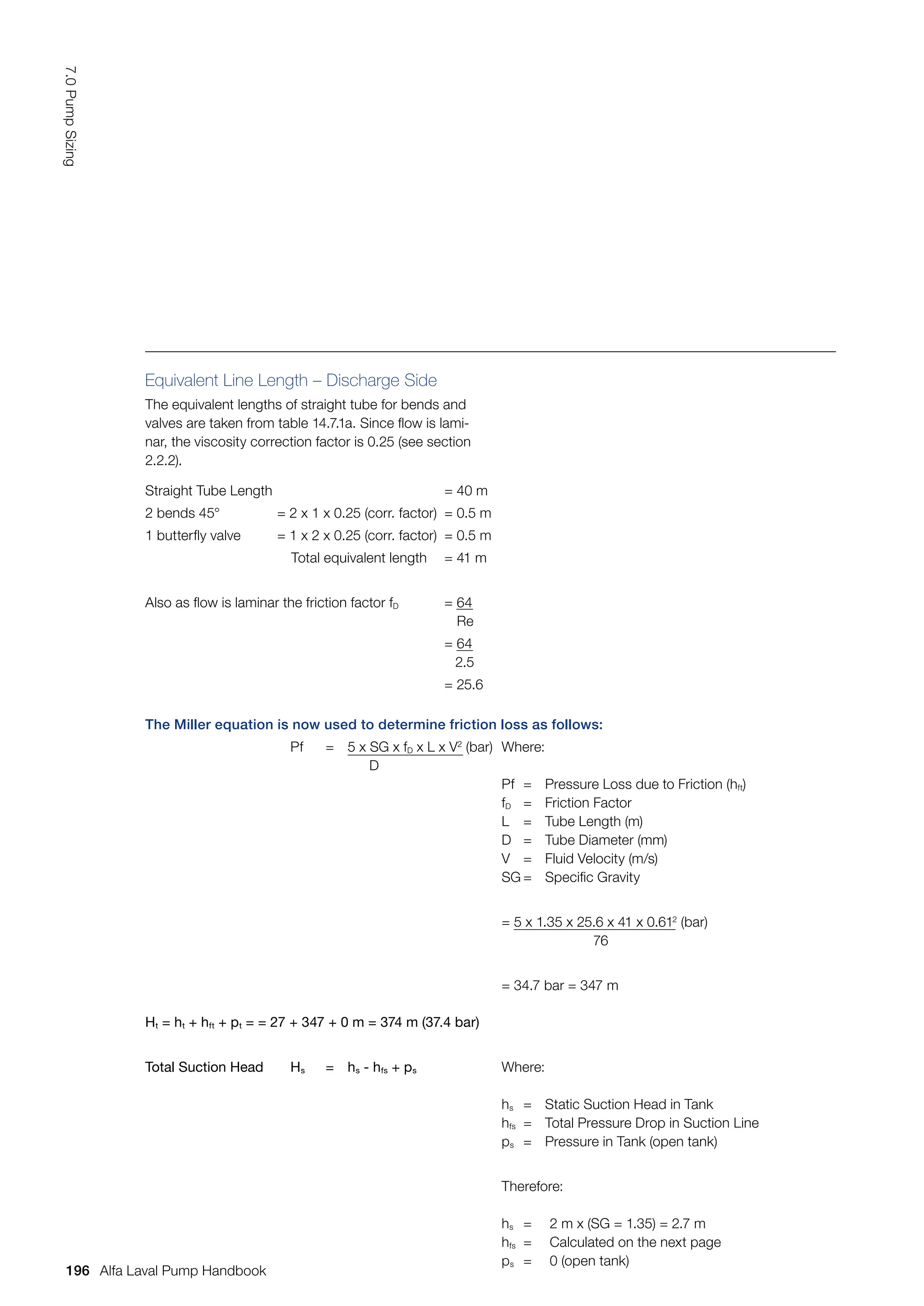
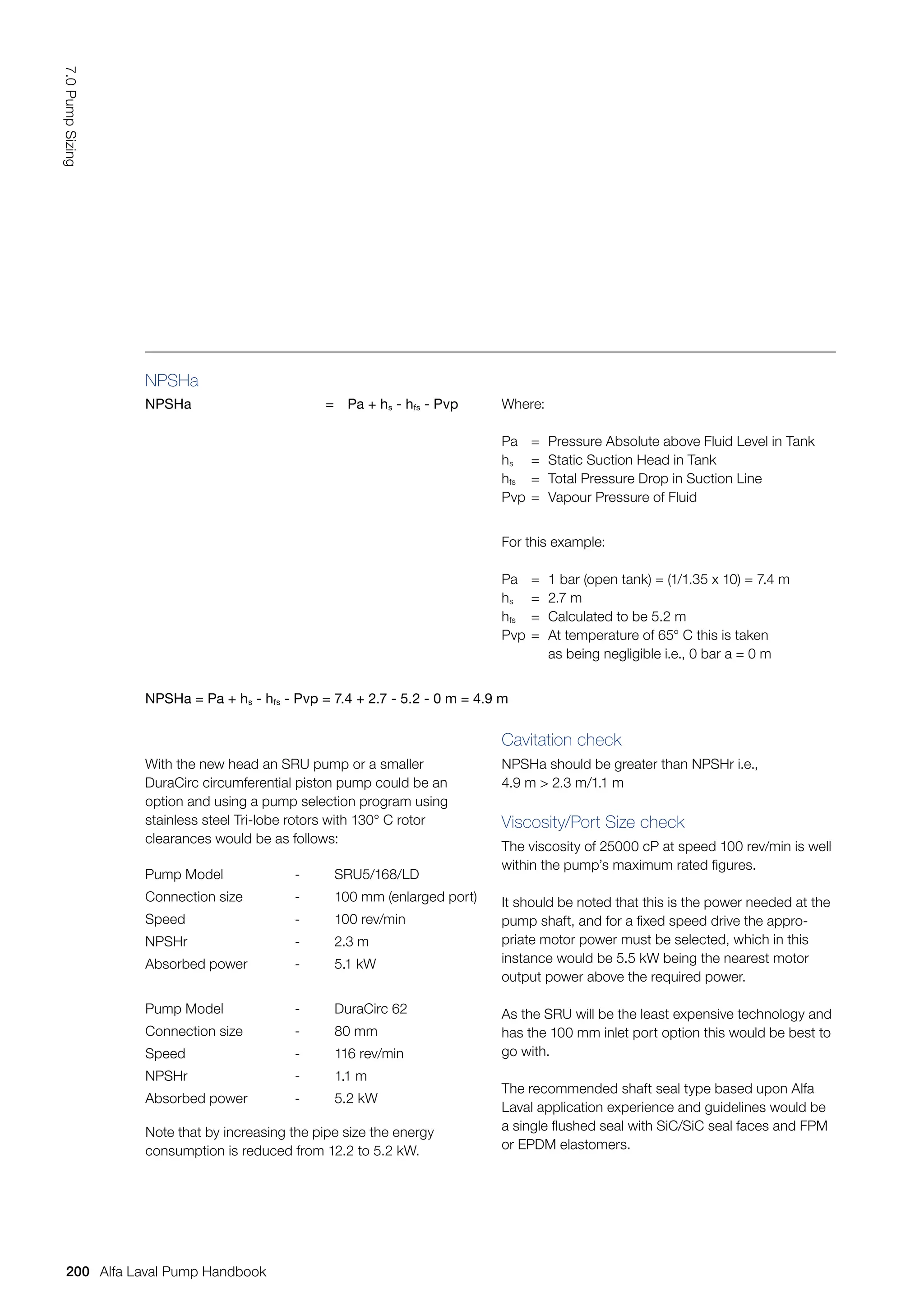
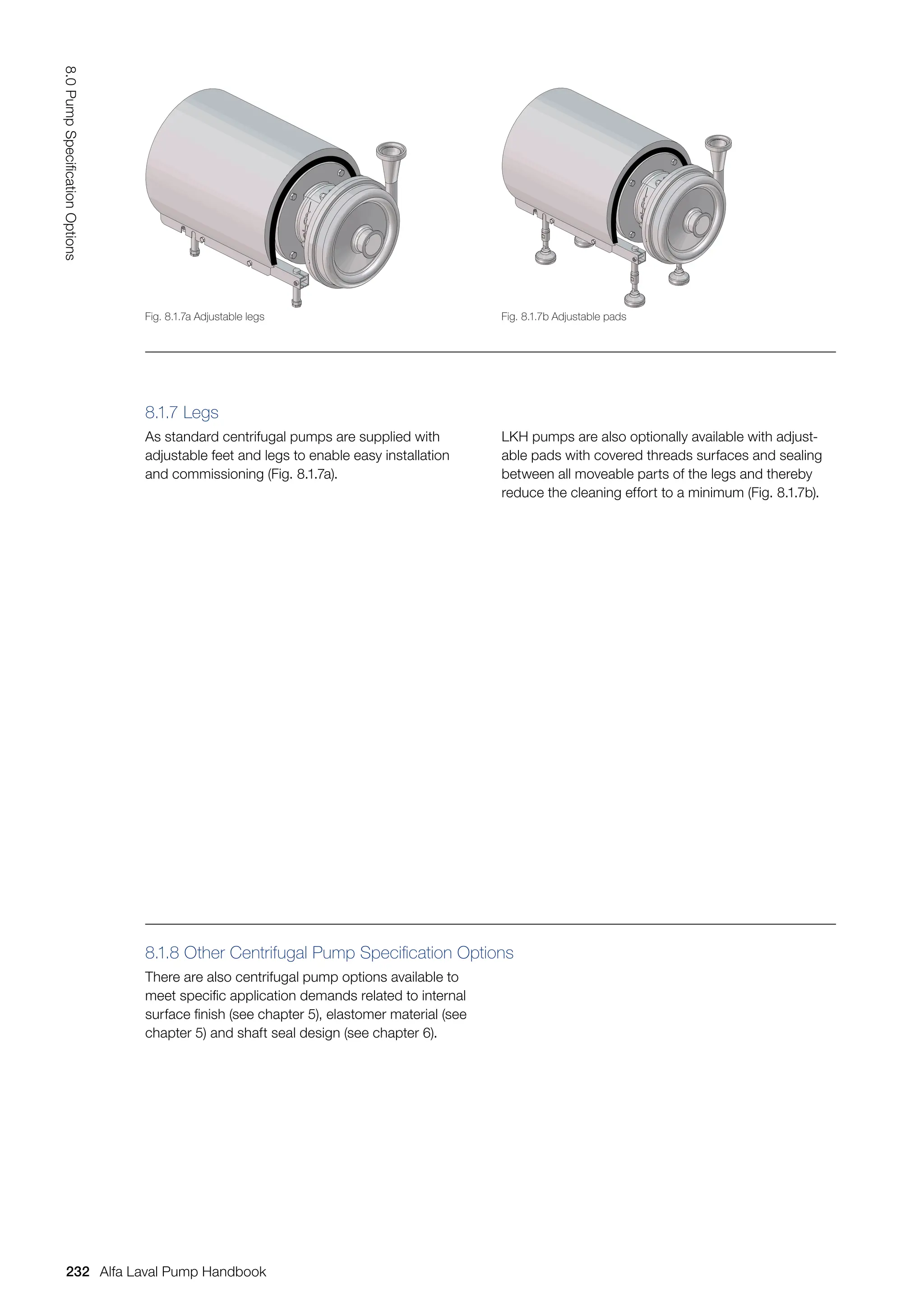
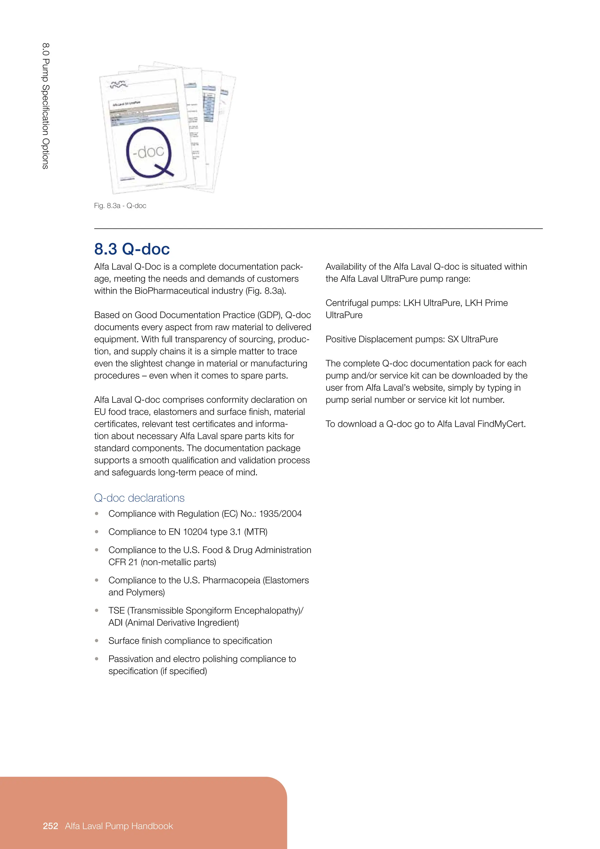
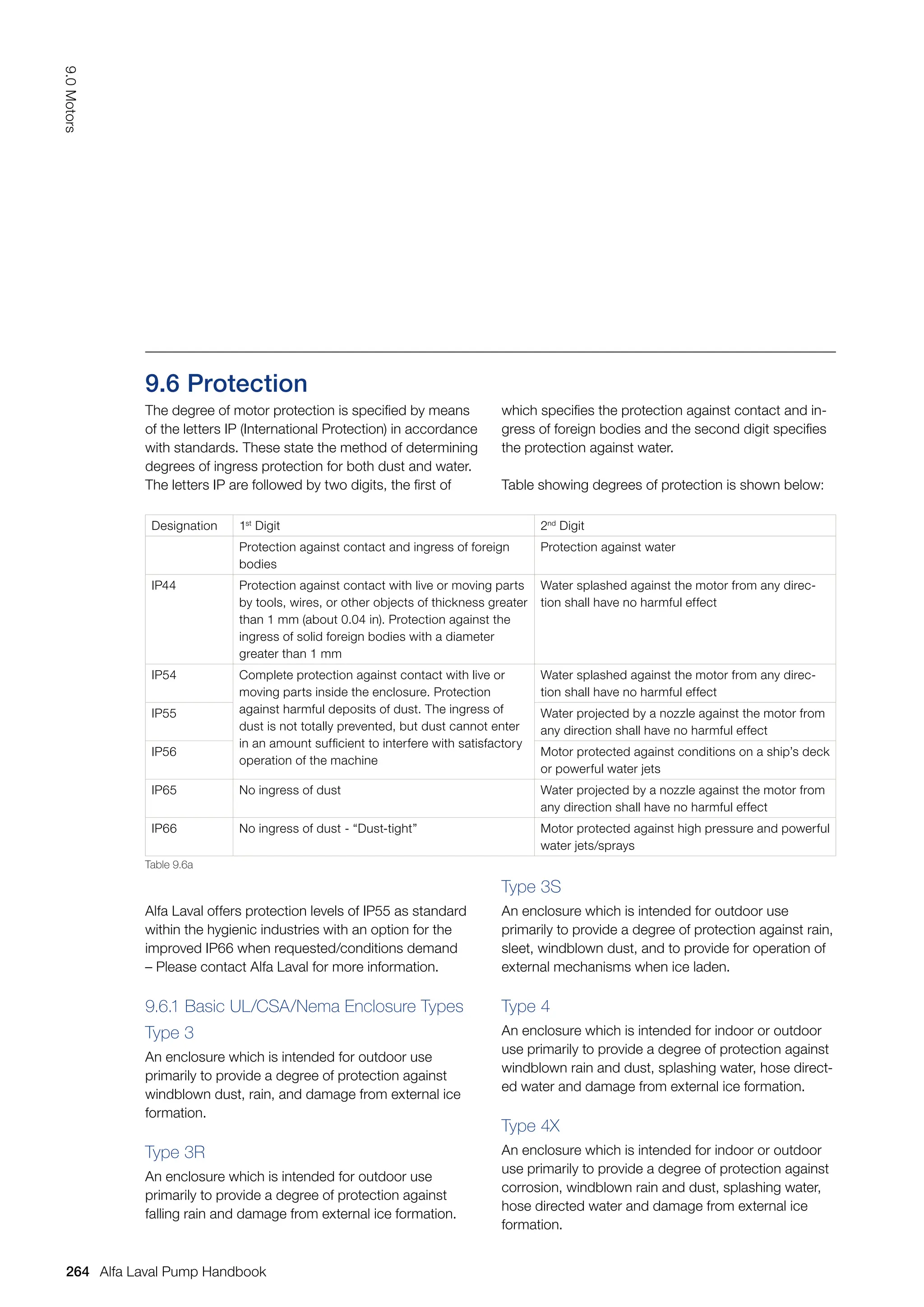
7.3.3 Alternative Pump Installations
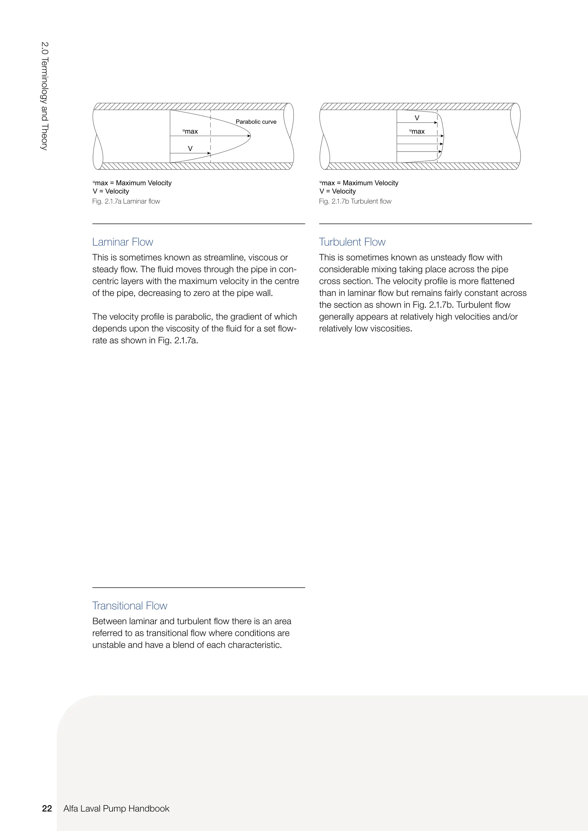
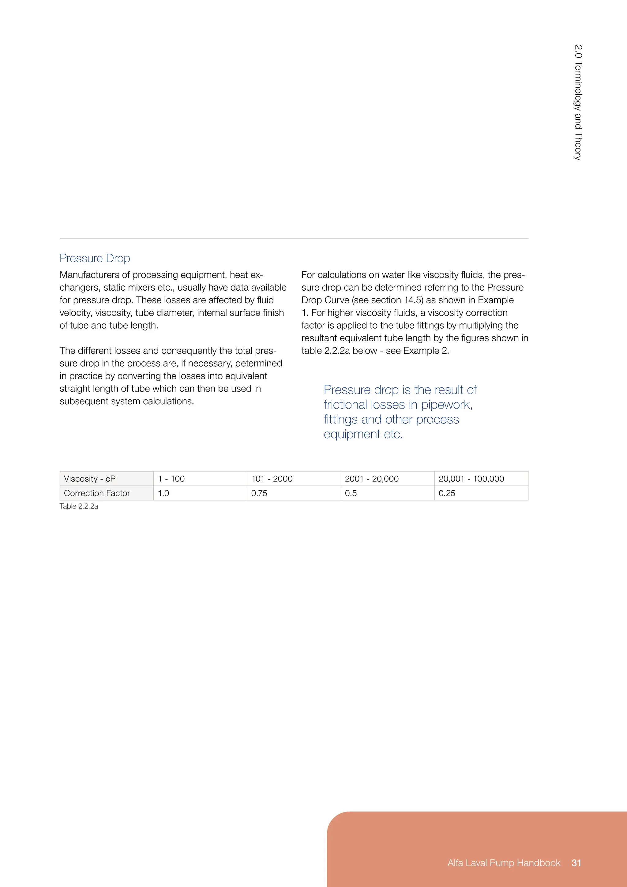
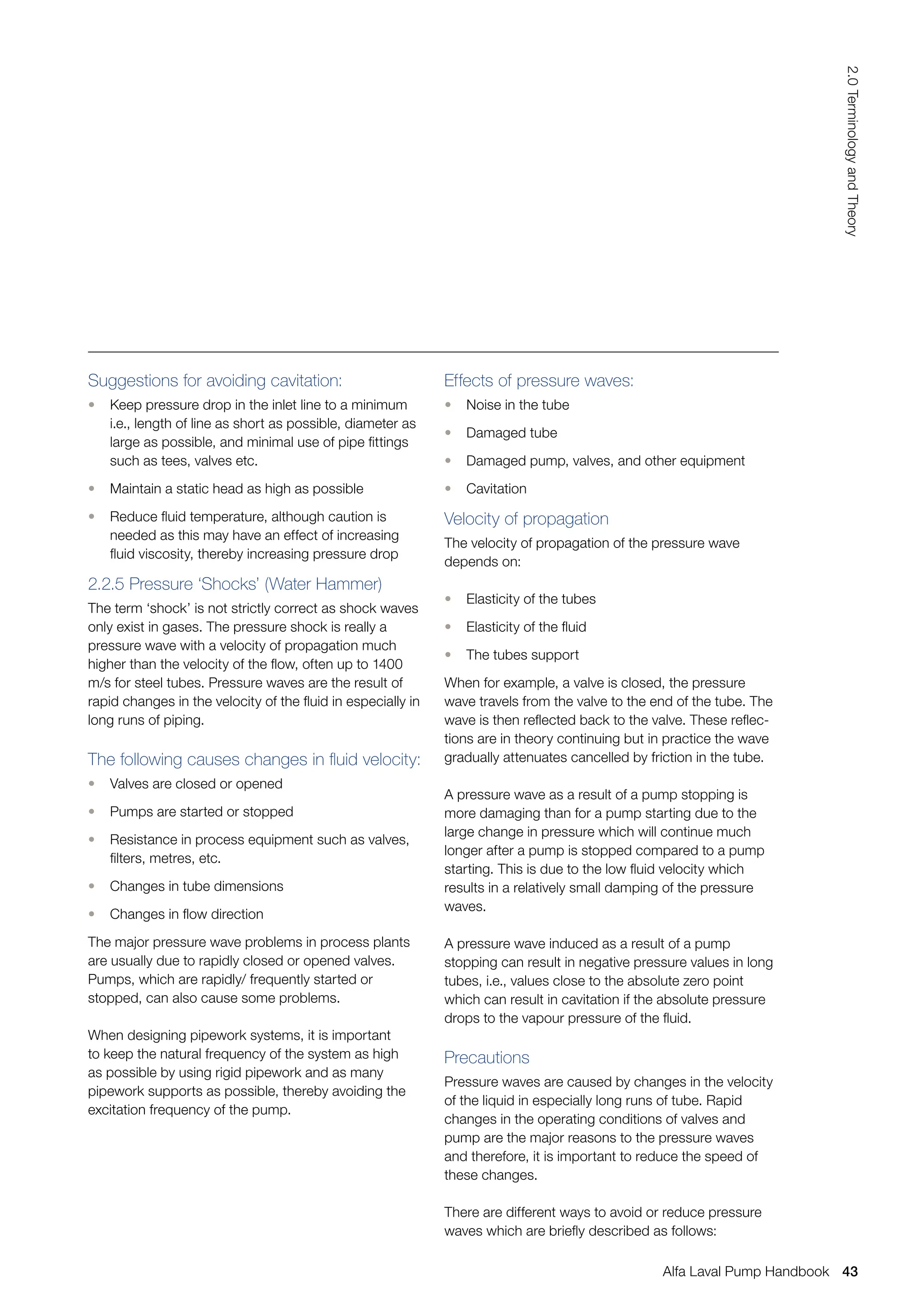
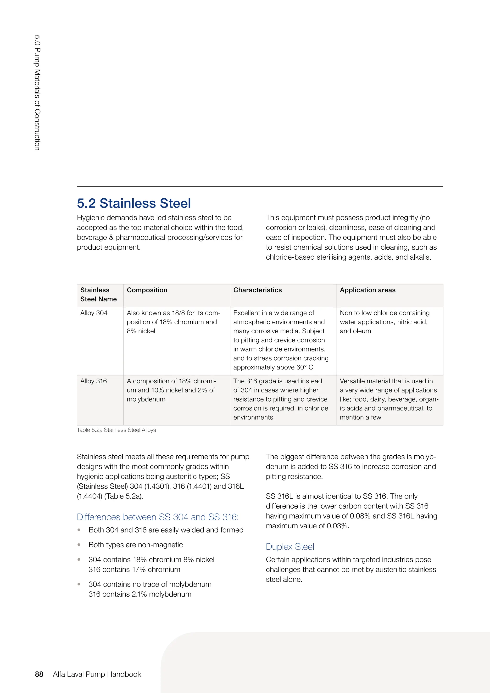
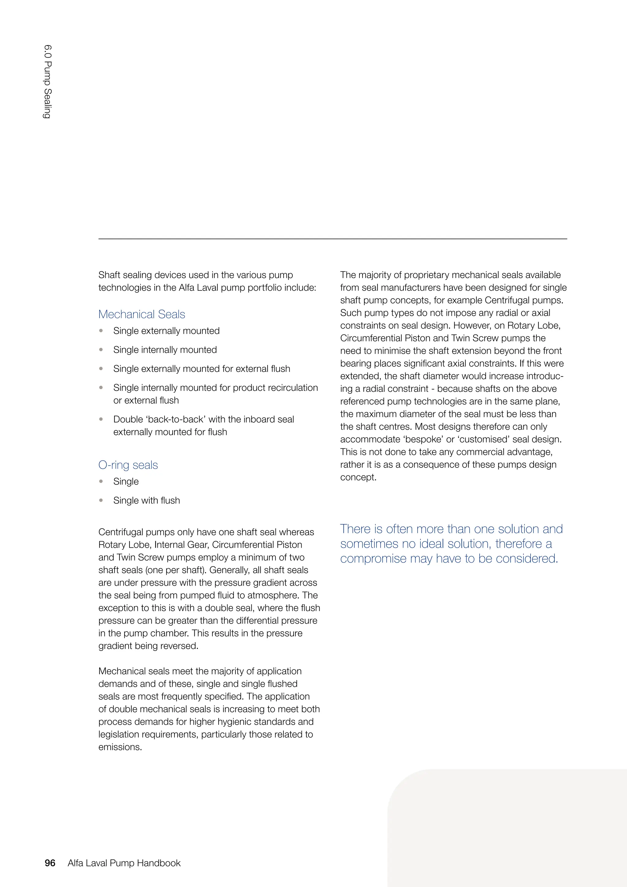
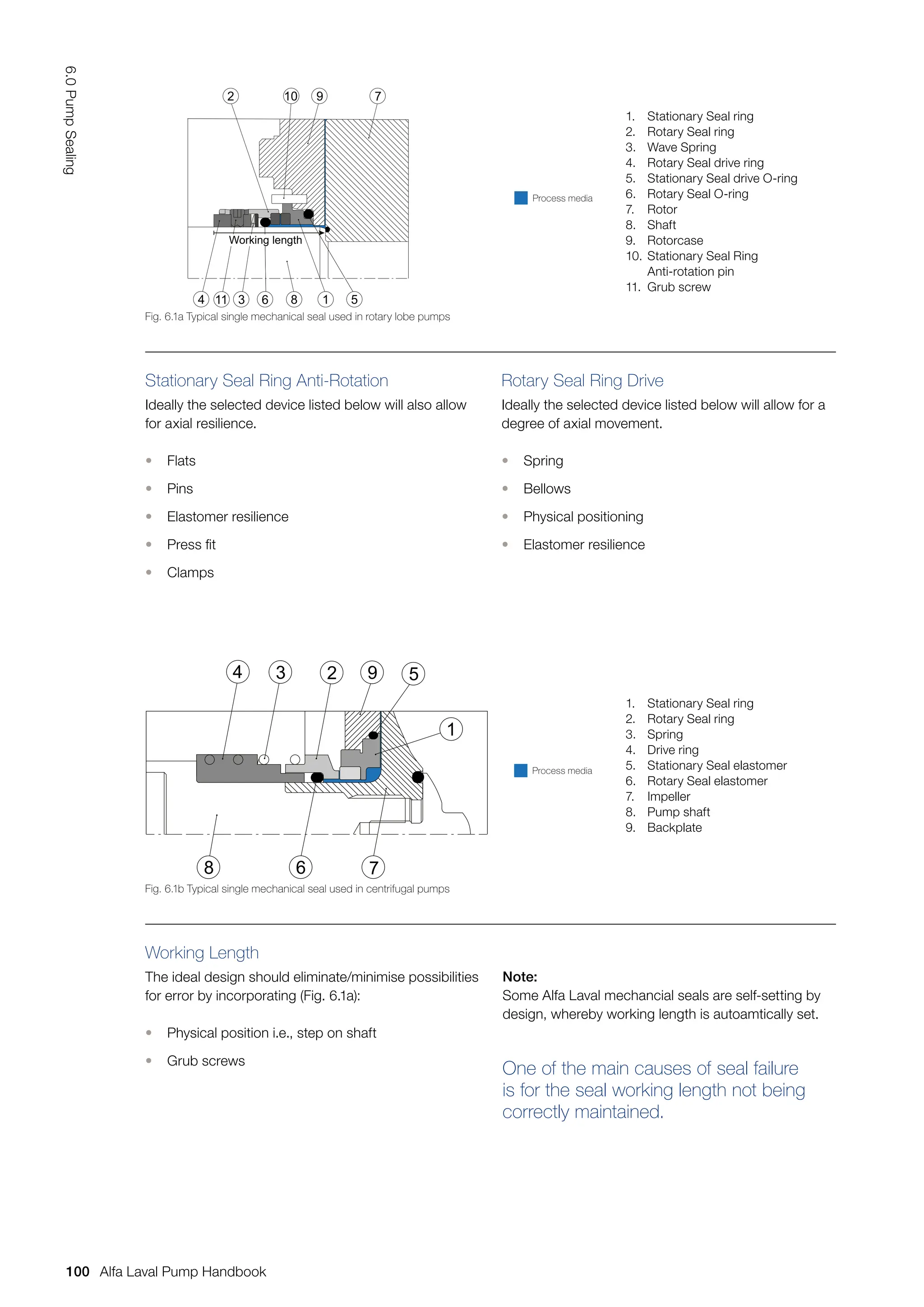
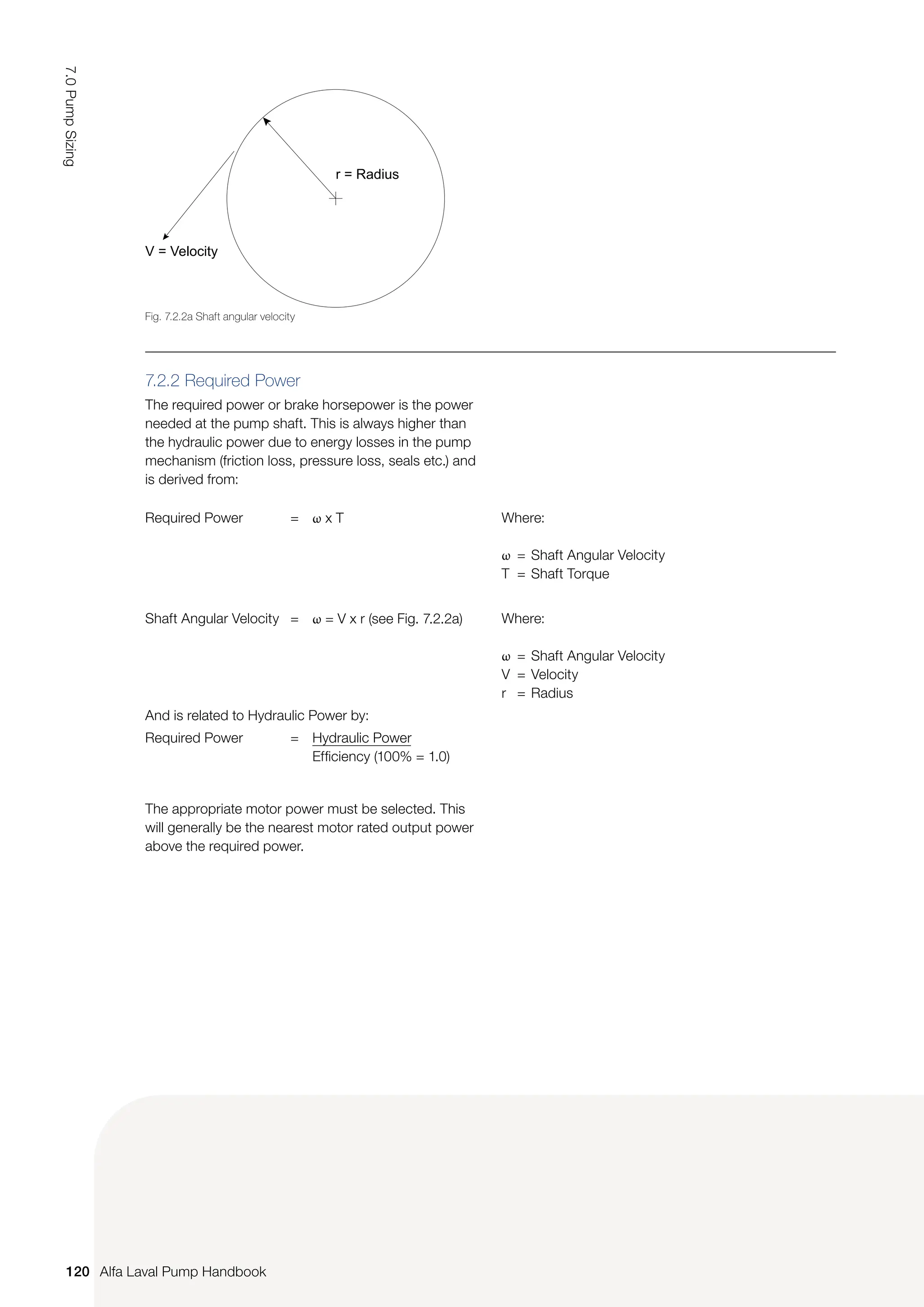
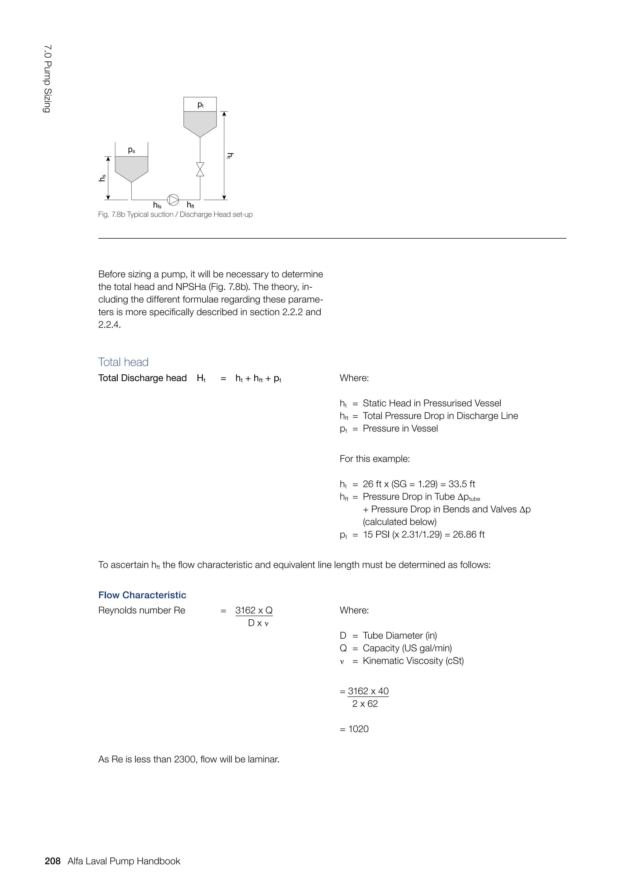
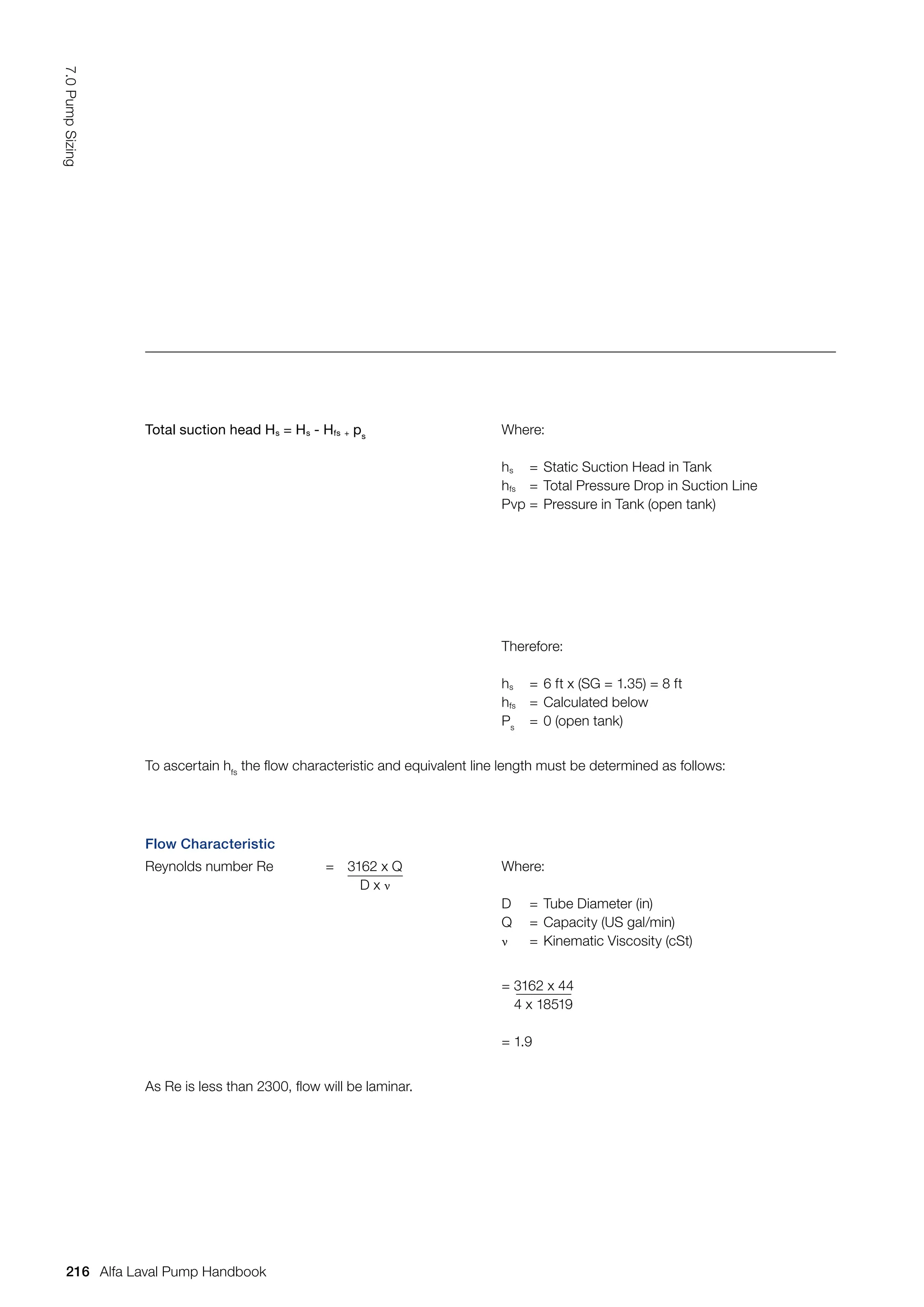
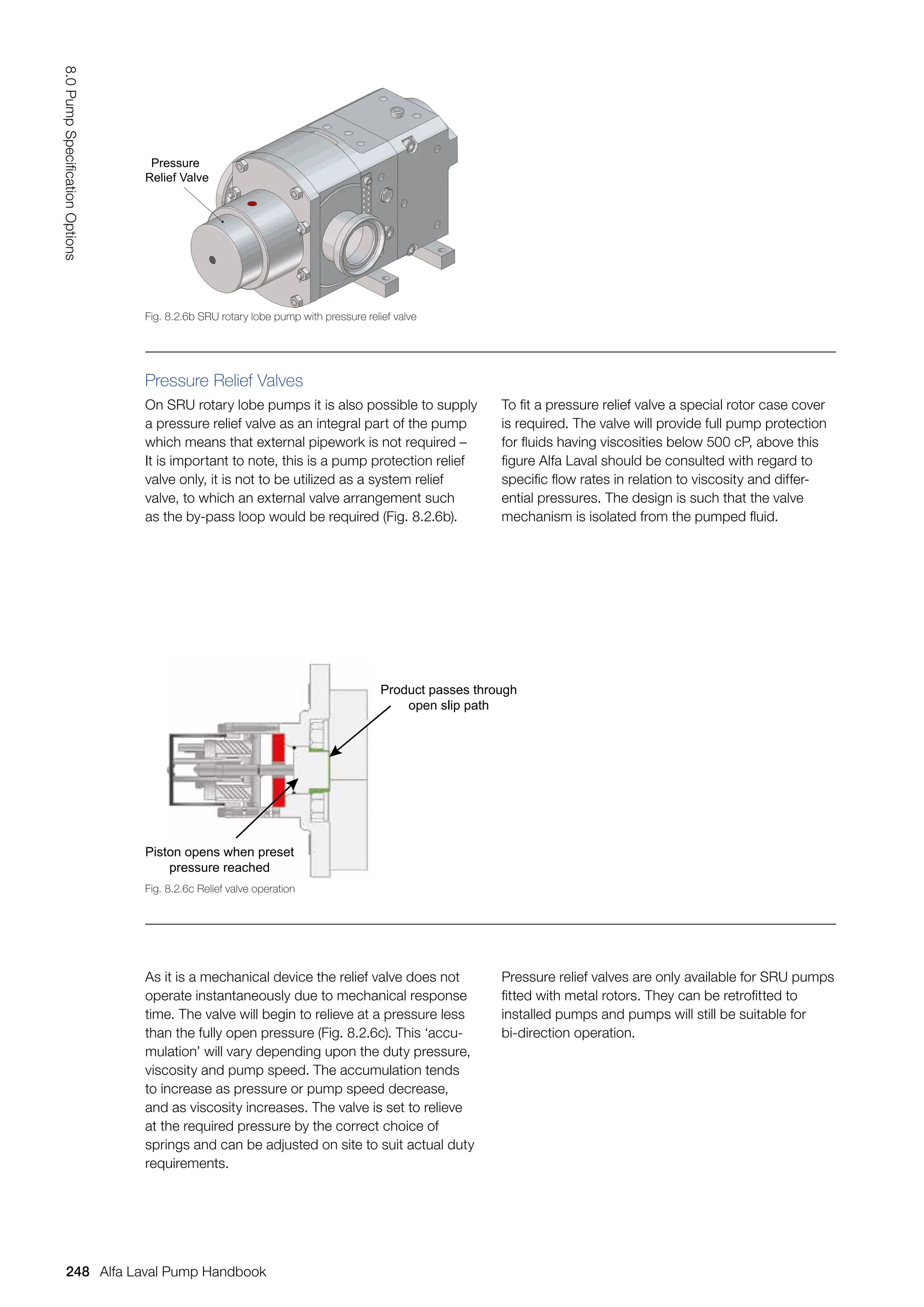
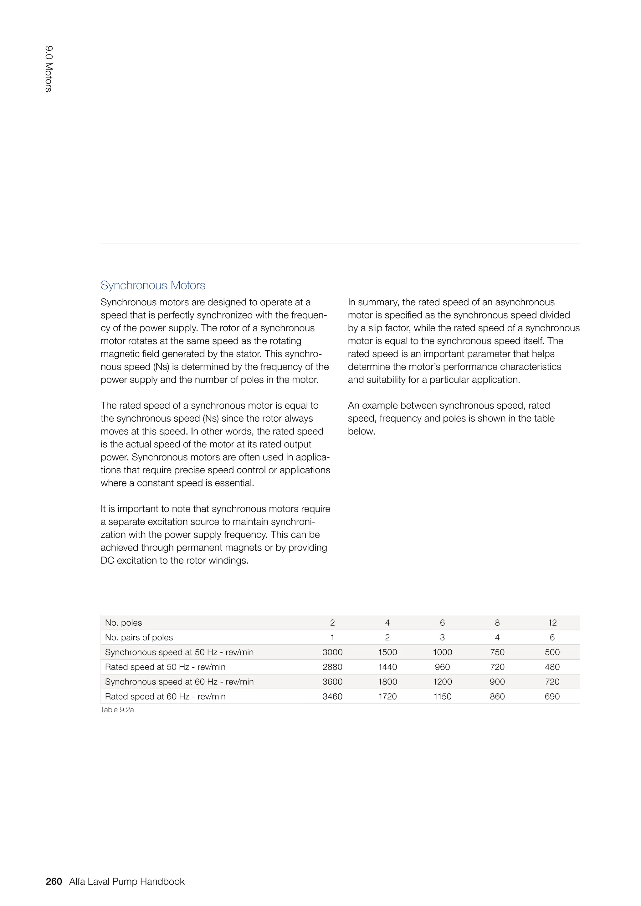
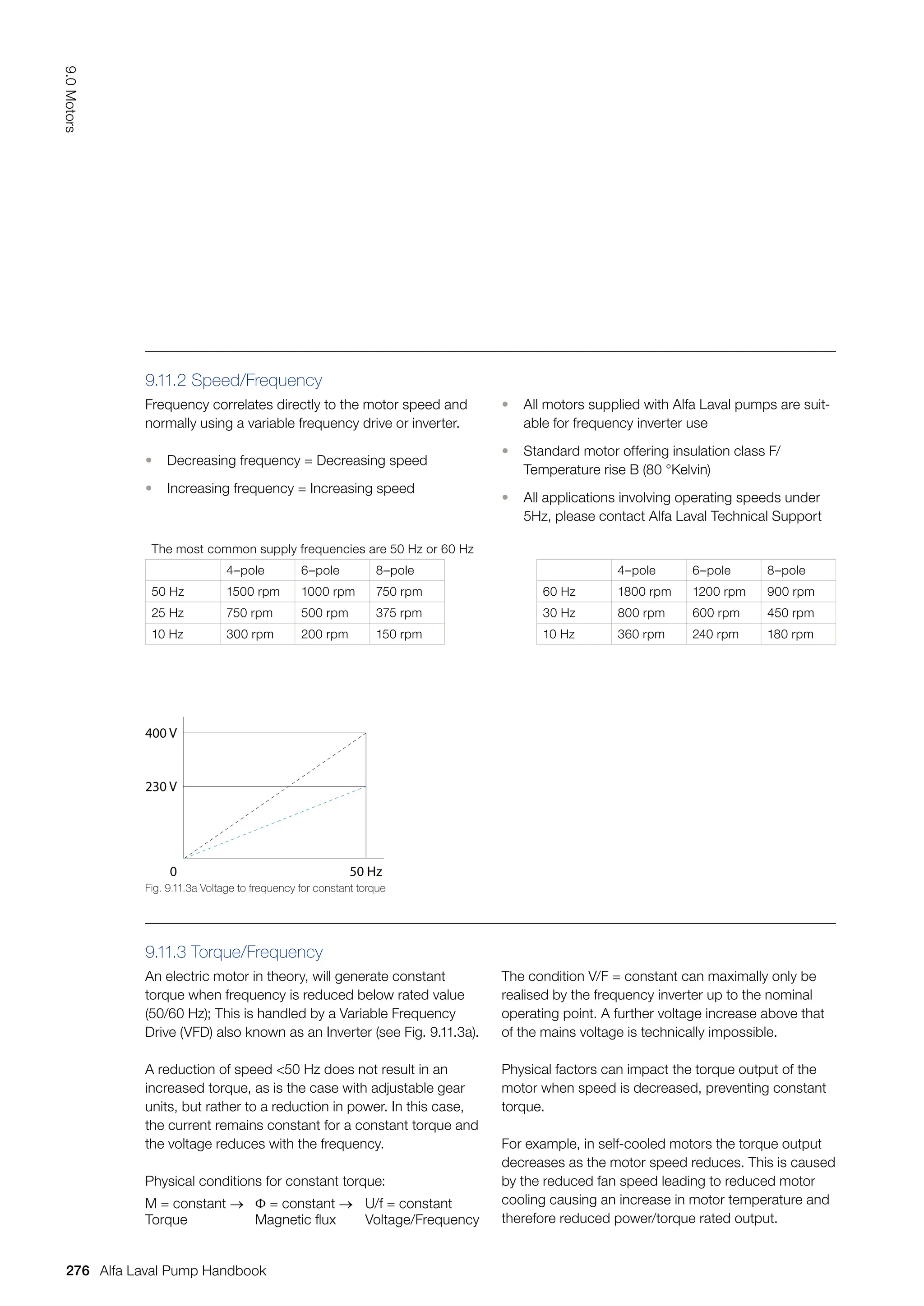
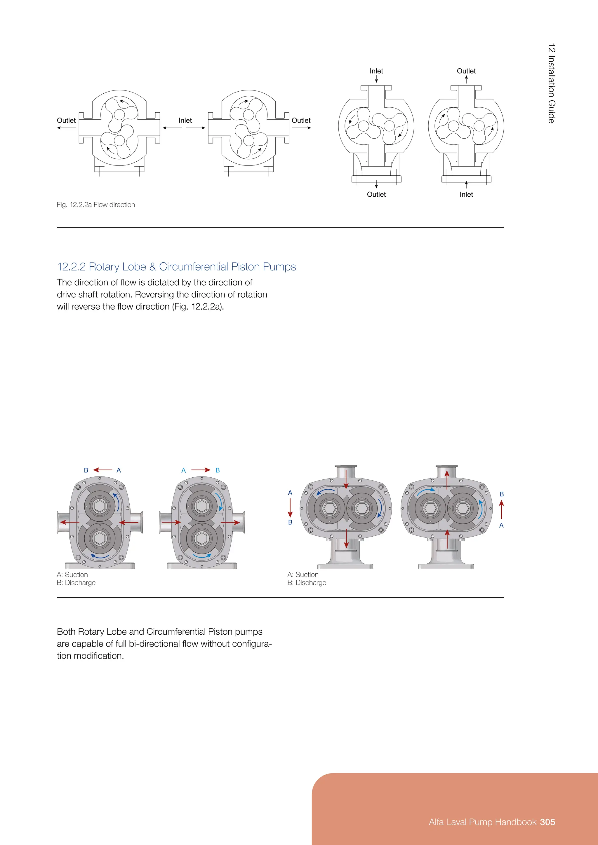
Pumps Coupled in Series
It is possible to increase the head in a pump installa-
tion by two or more pumps being coupled in series
(see Fig. 7.3.3a).
The Capacity (Q) will always be constant throughout
the pump series (see Fig. 7.3.3b).
The head can vary depending on the pump sizes.
The outlet of pump 1 is connected to the inlet of
pump 2.
Pump 2 must be able to withstand the outlet head
from pump 1.
Fig. 7.3.3a Principle of connection
2
H = H1 + H2 Q = Constant
1
H2
H1
133
7.0
Pump
Sizing
Alfa Laval Pump Handbook](https://image.slidesharecdn.com/pump-handbook-2024-251113133245-895f754e/75/Alfa-Laval-Pump-Handbook-Second-Edition-2023-135-2048.jpg)
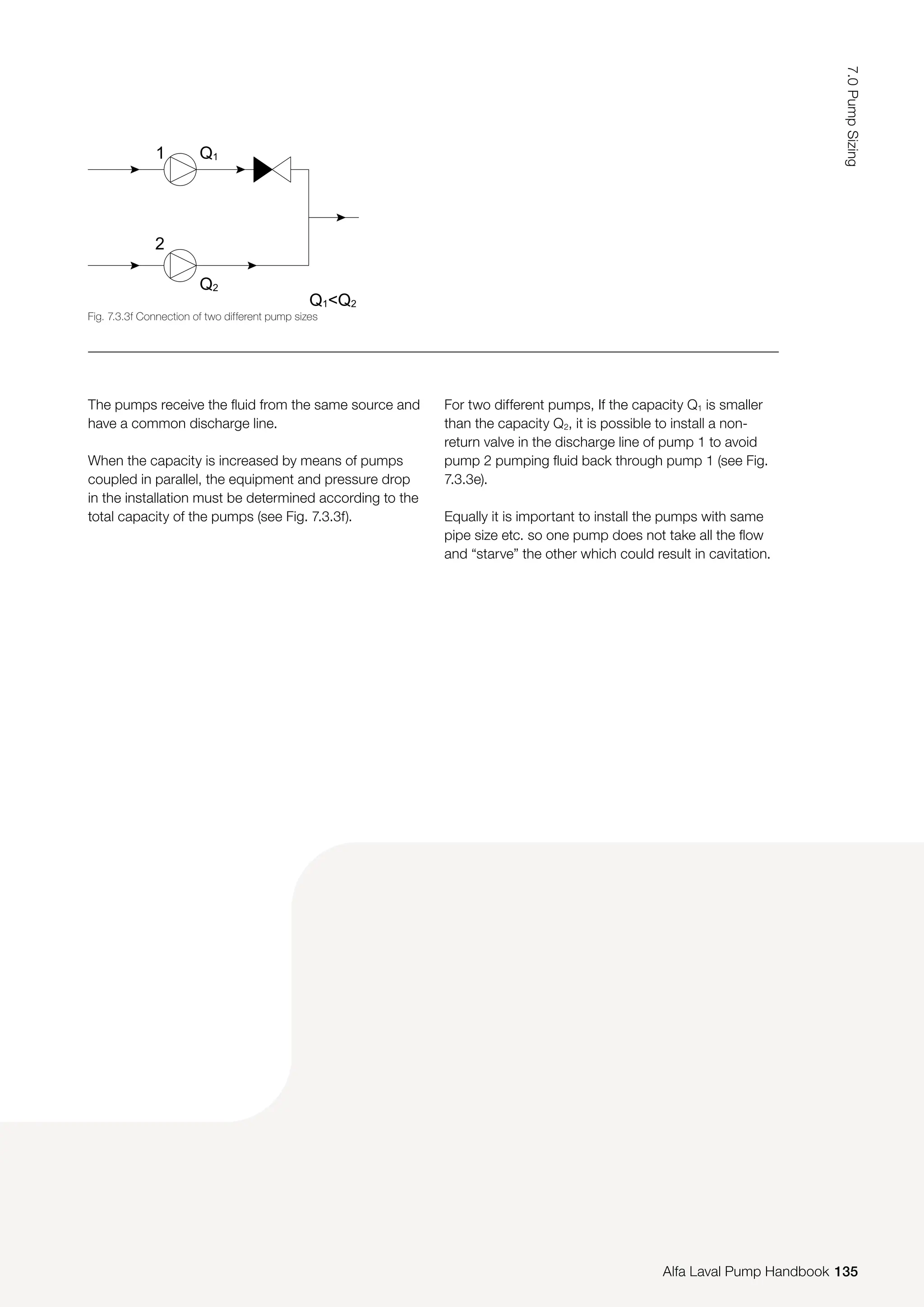


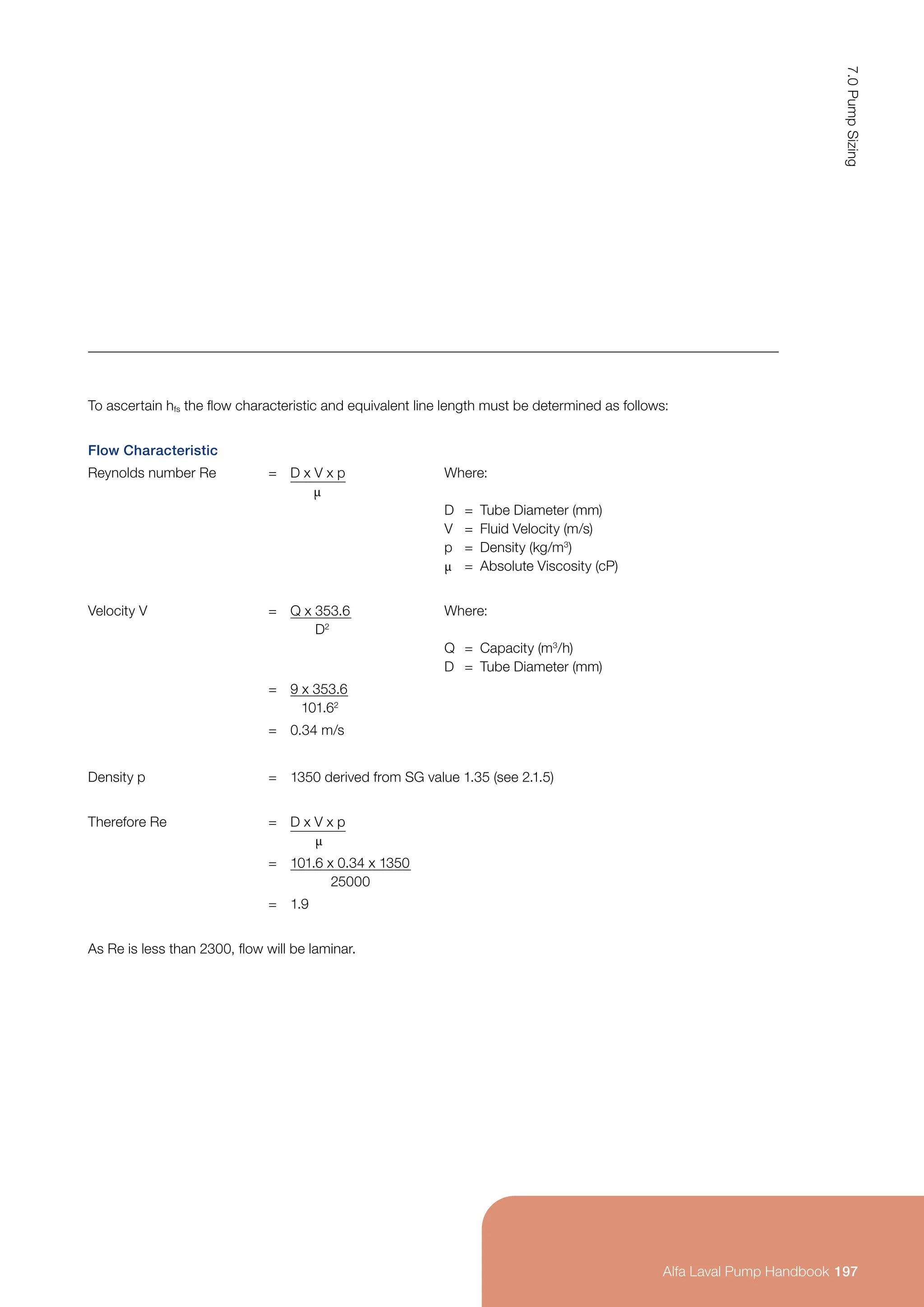
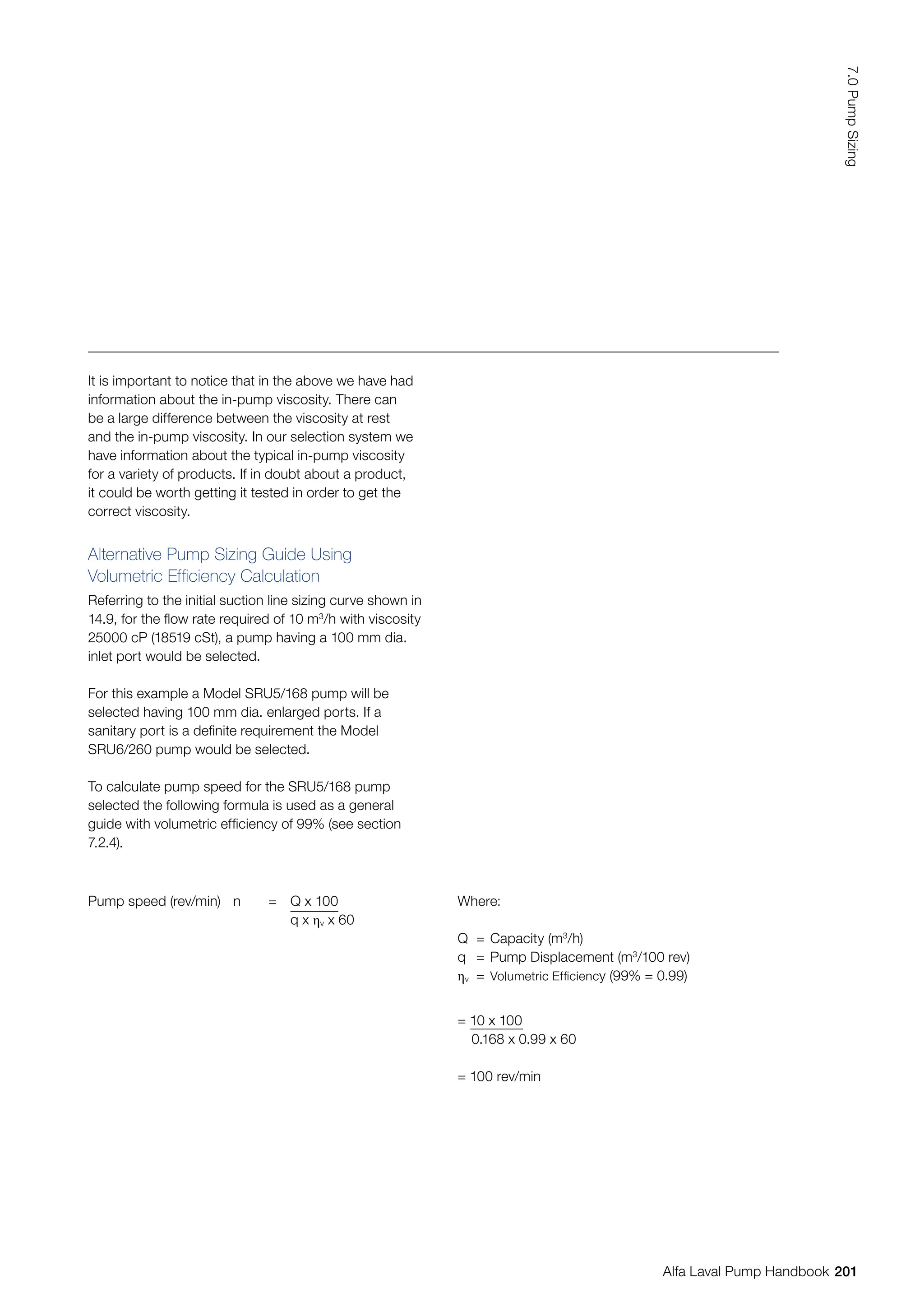
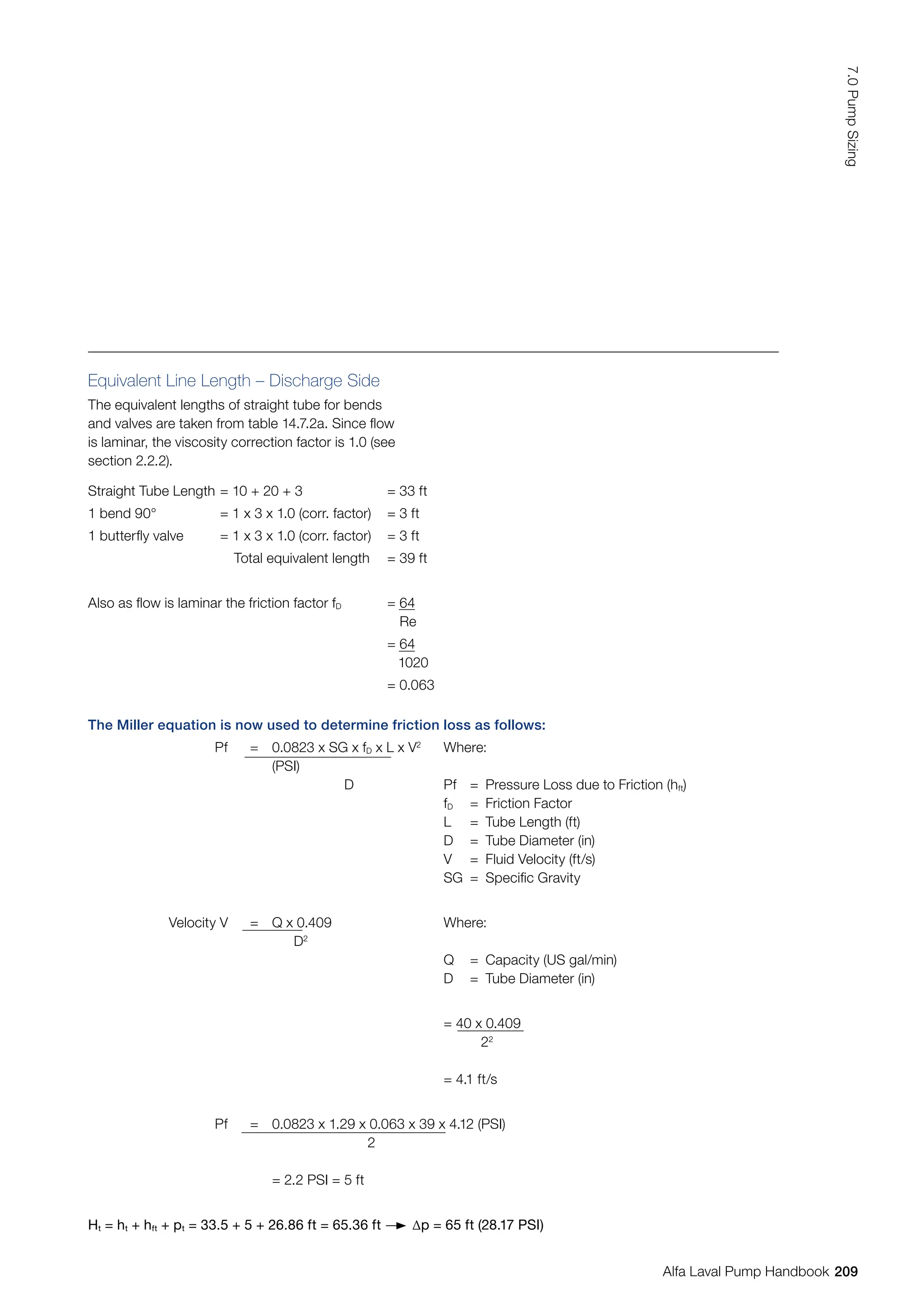
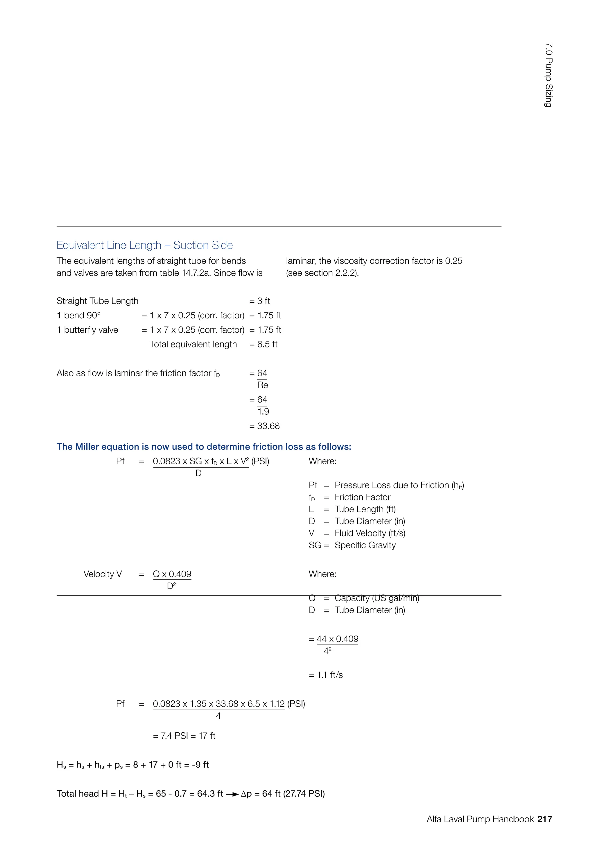
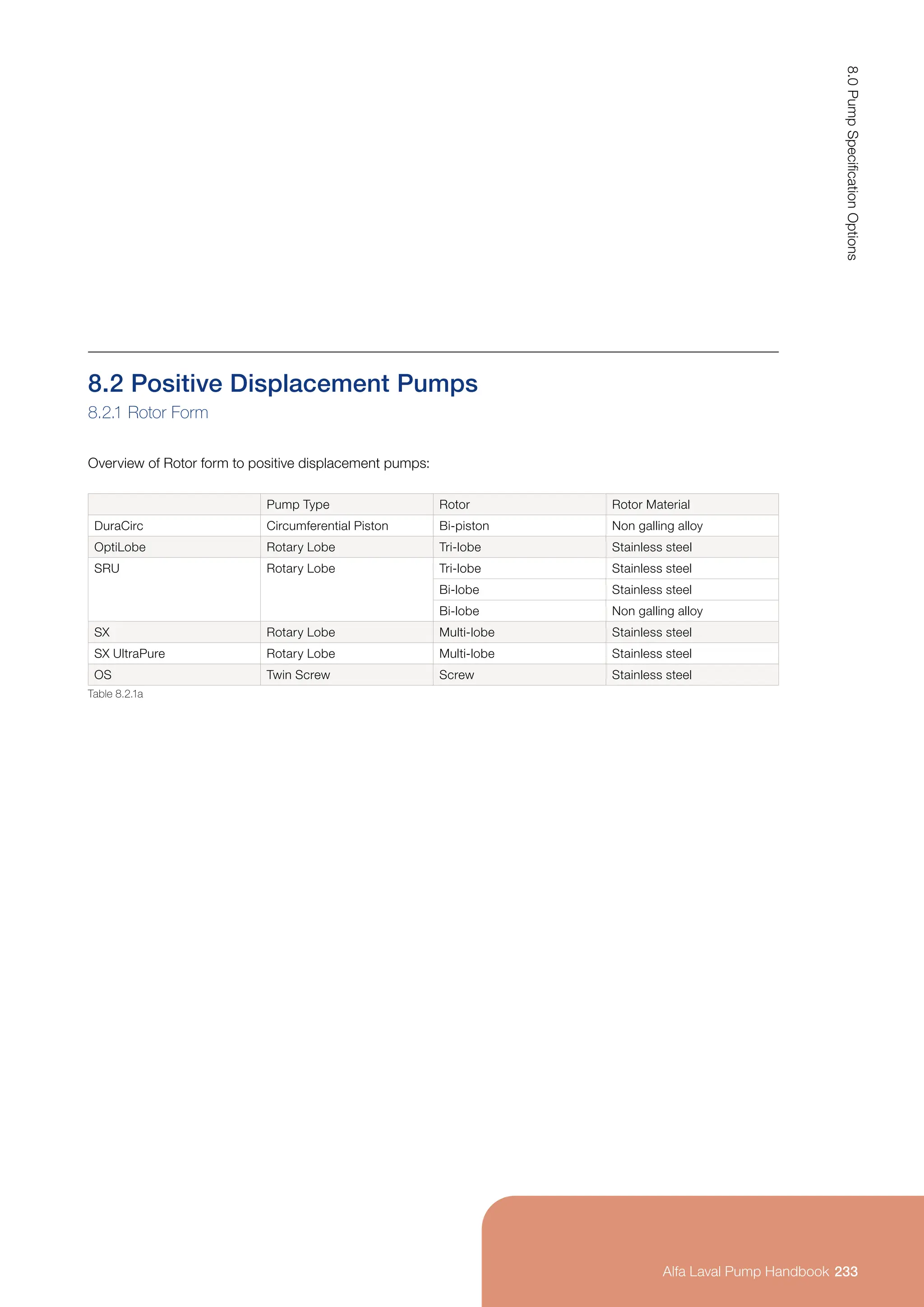
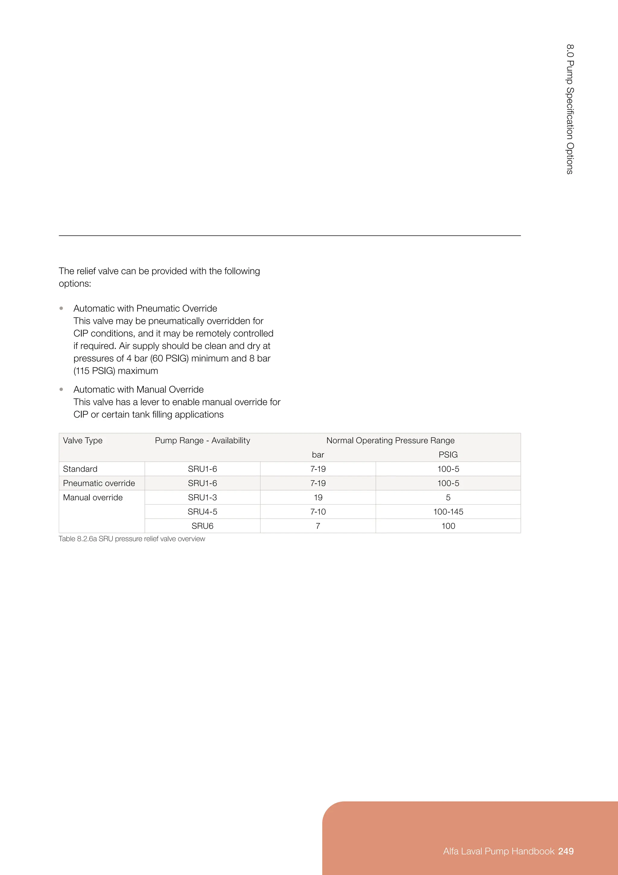
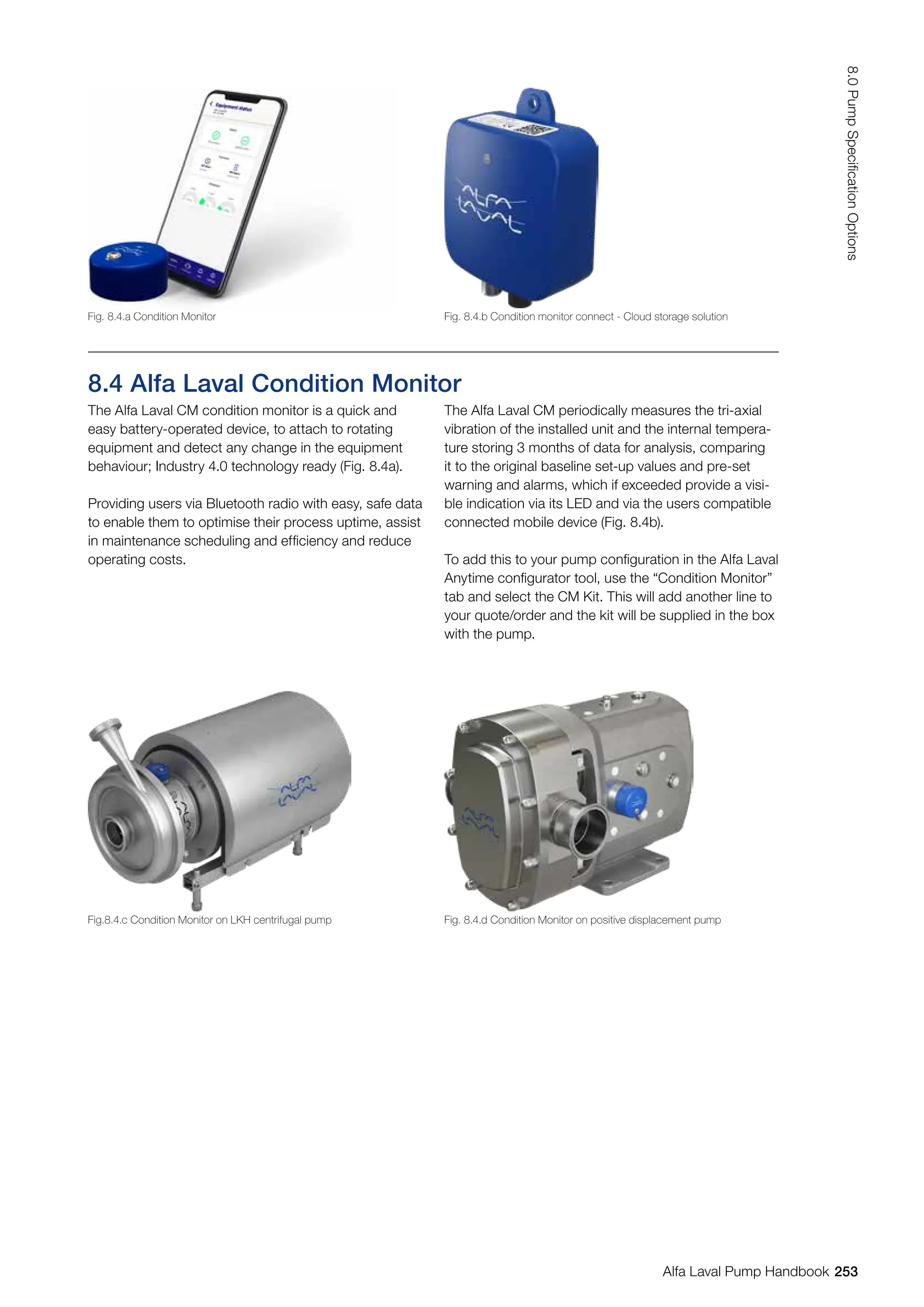
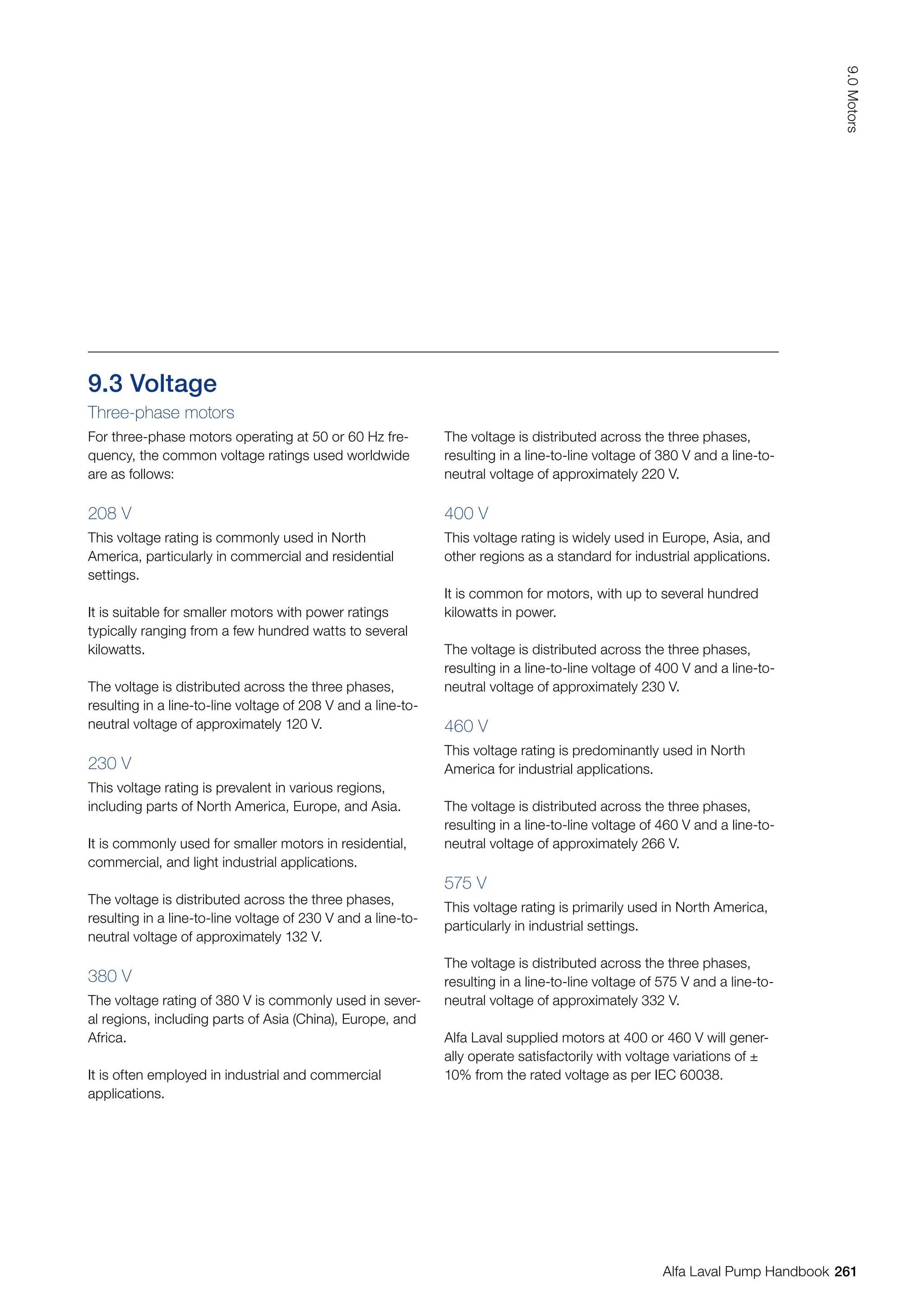
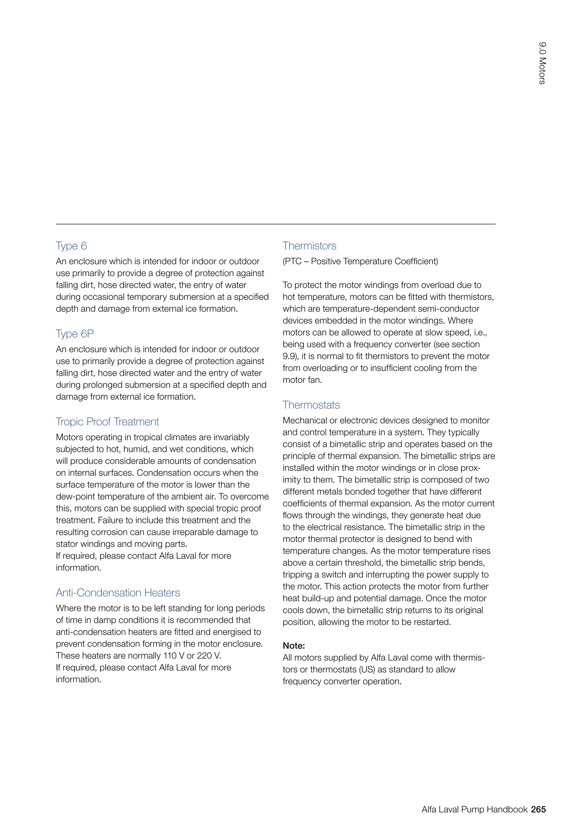
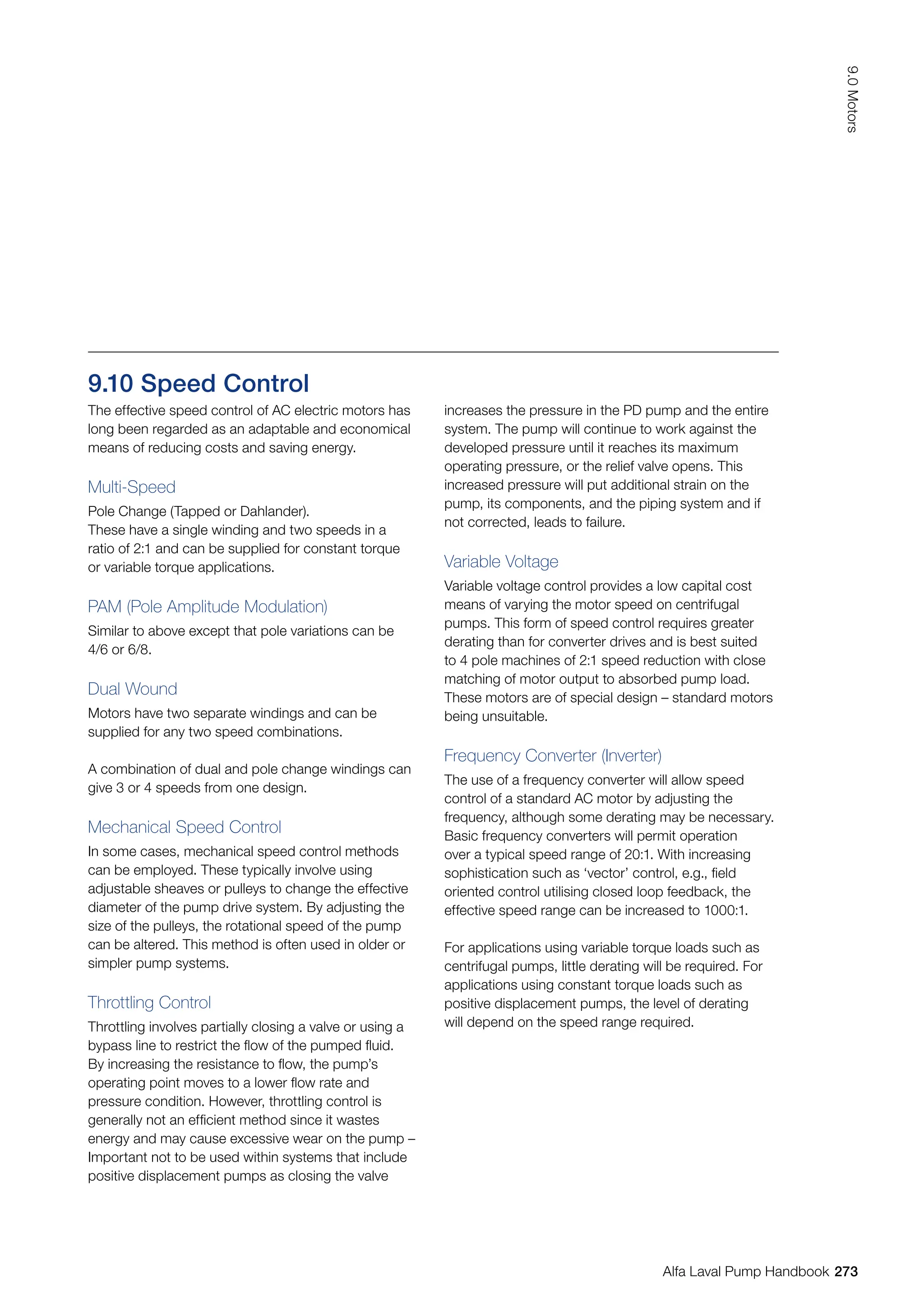
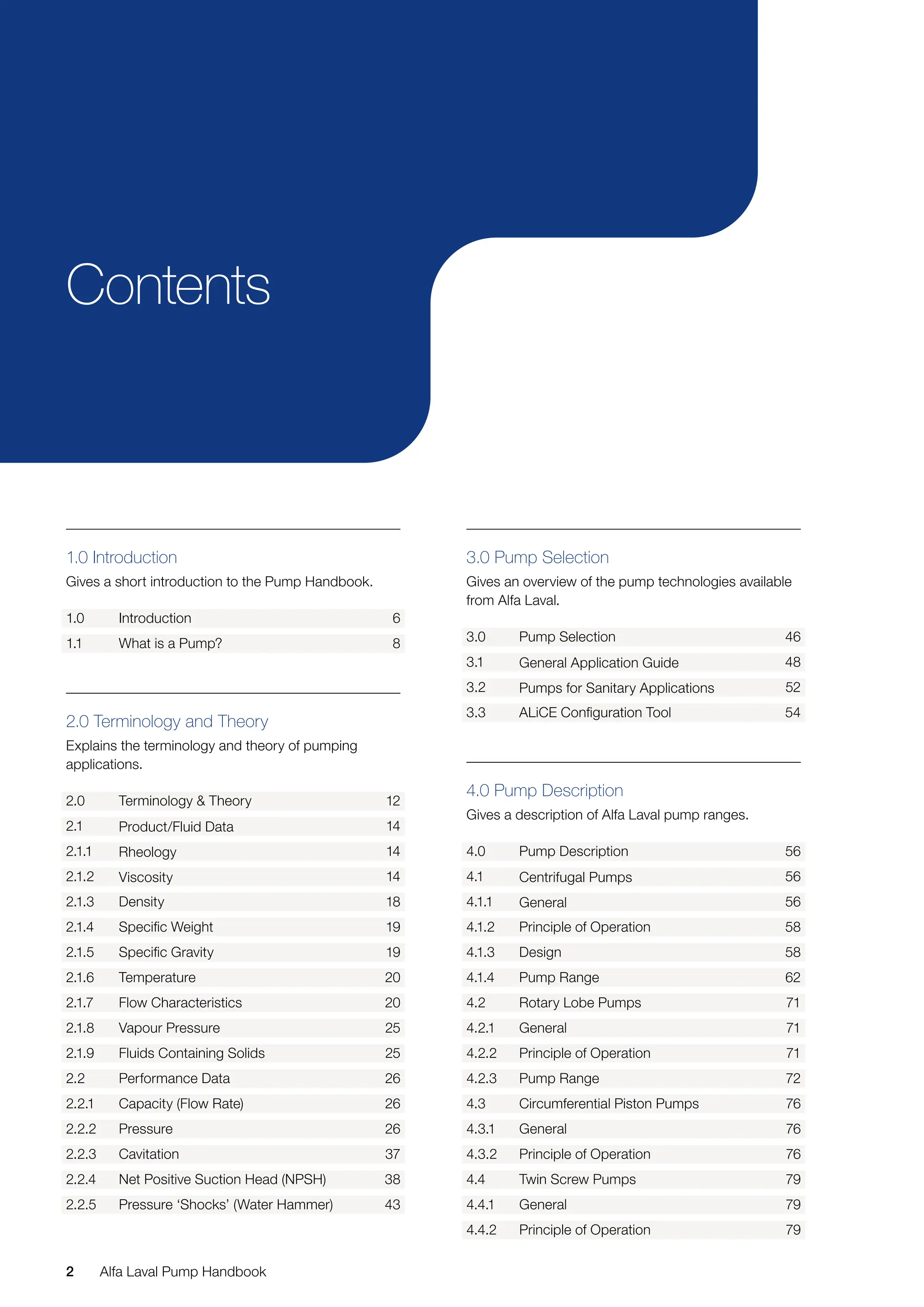
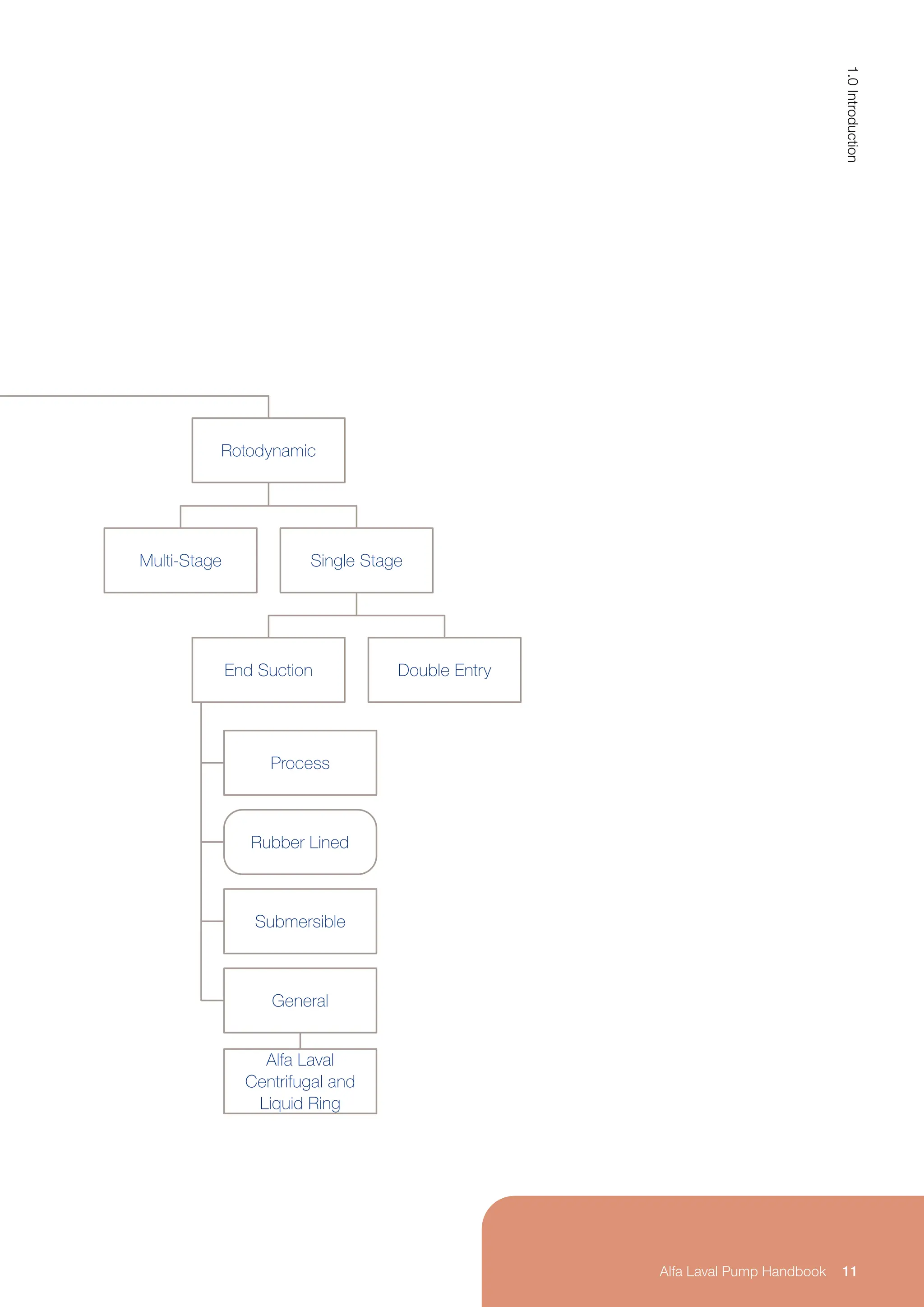
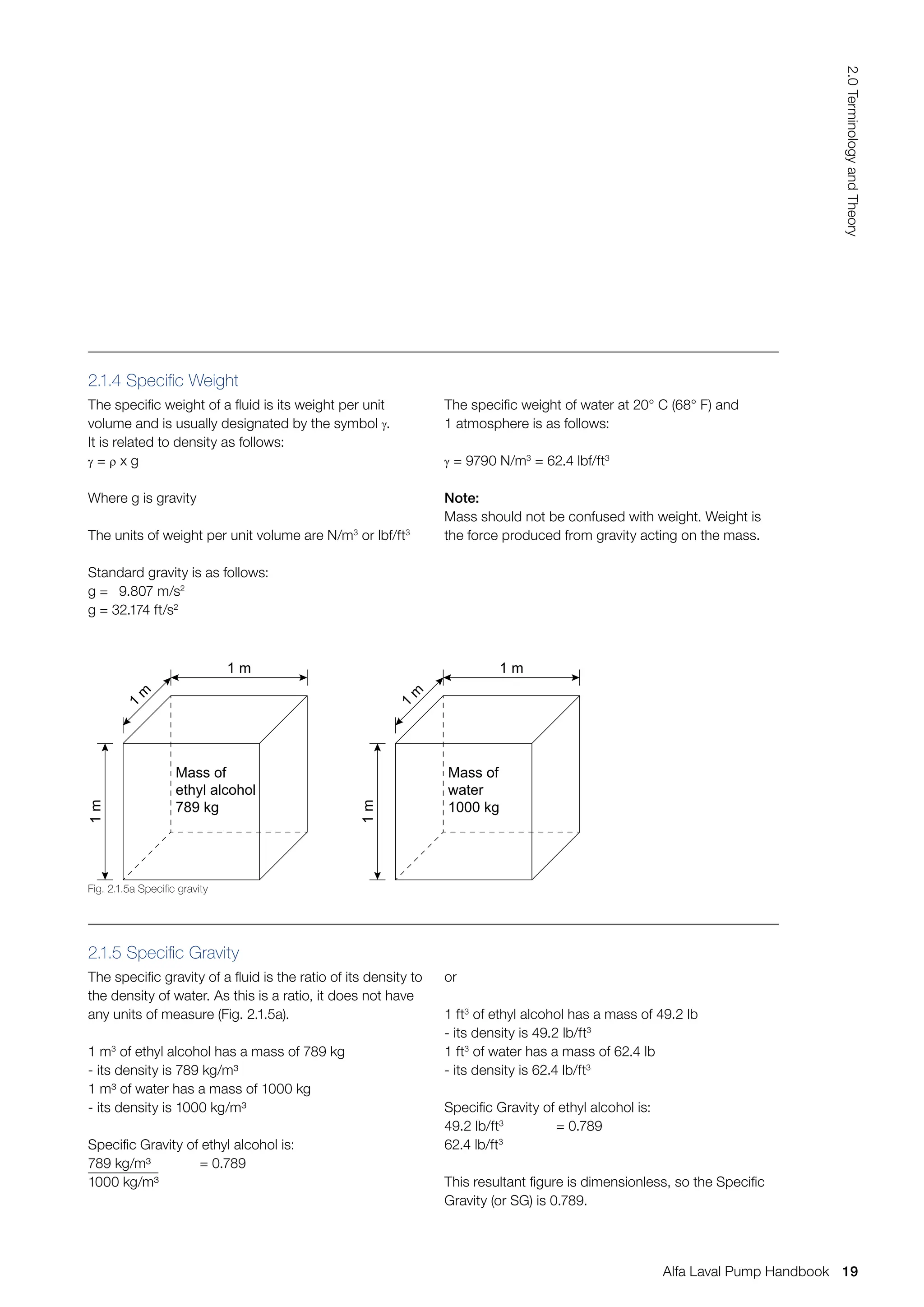
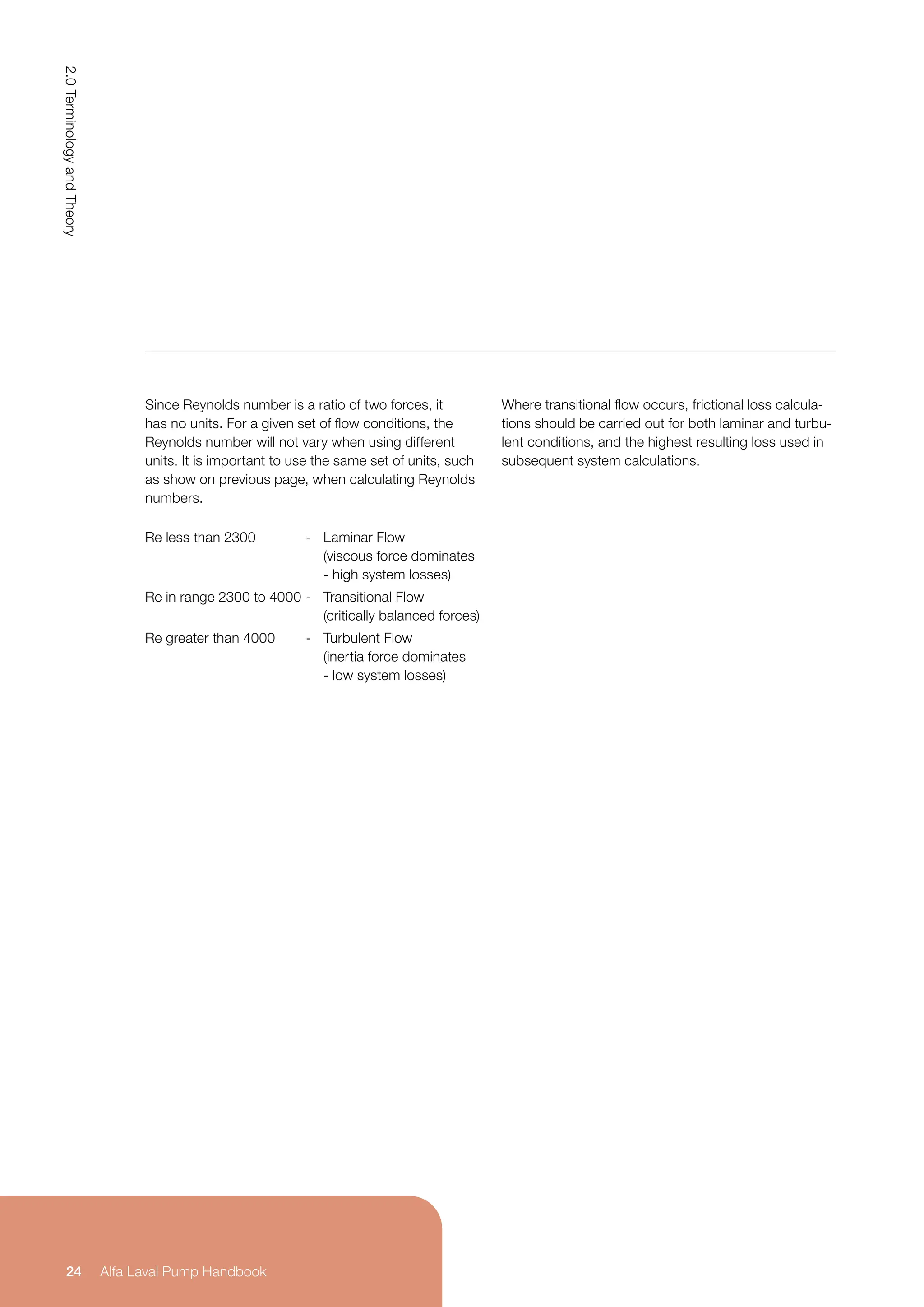
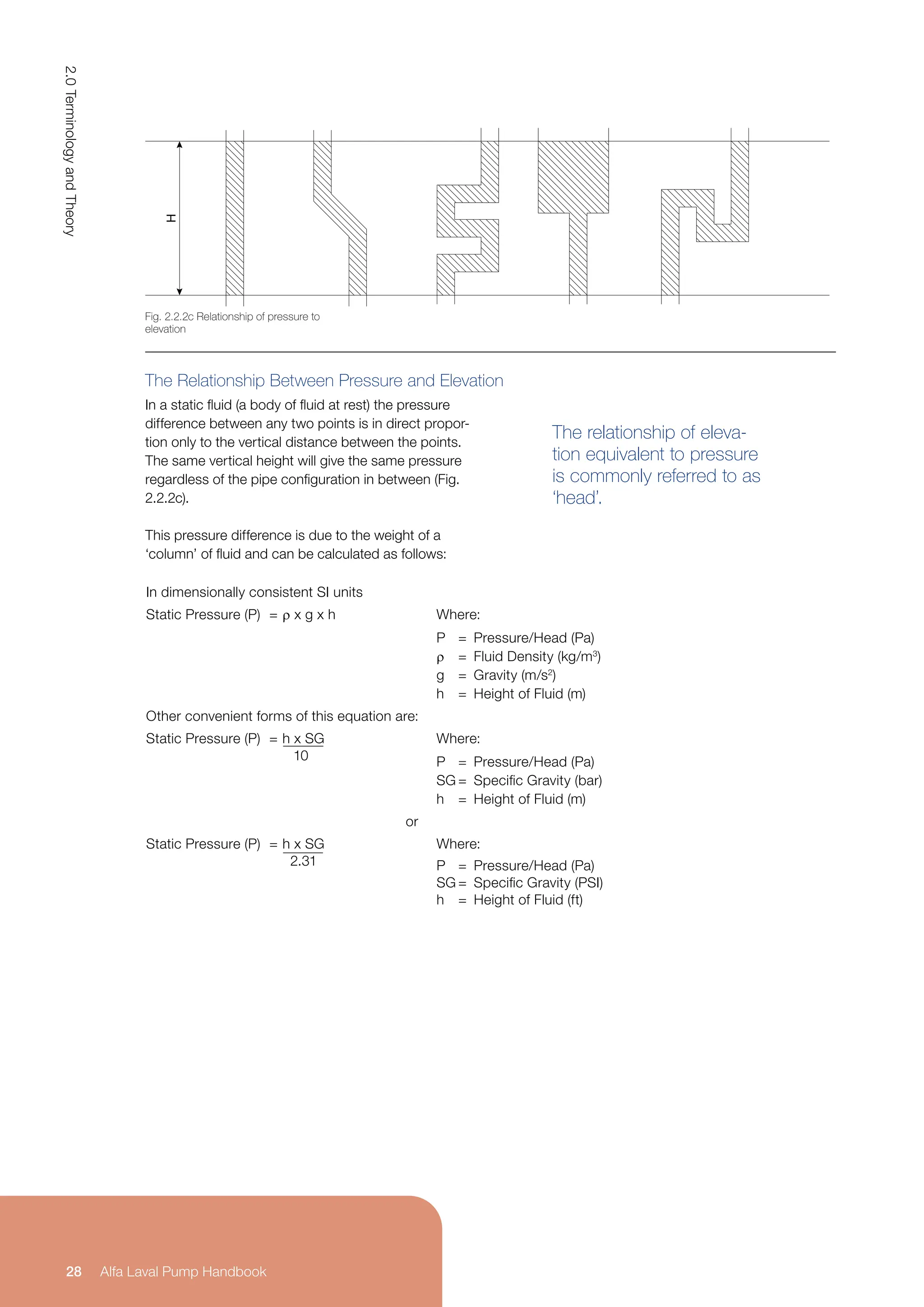
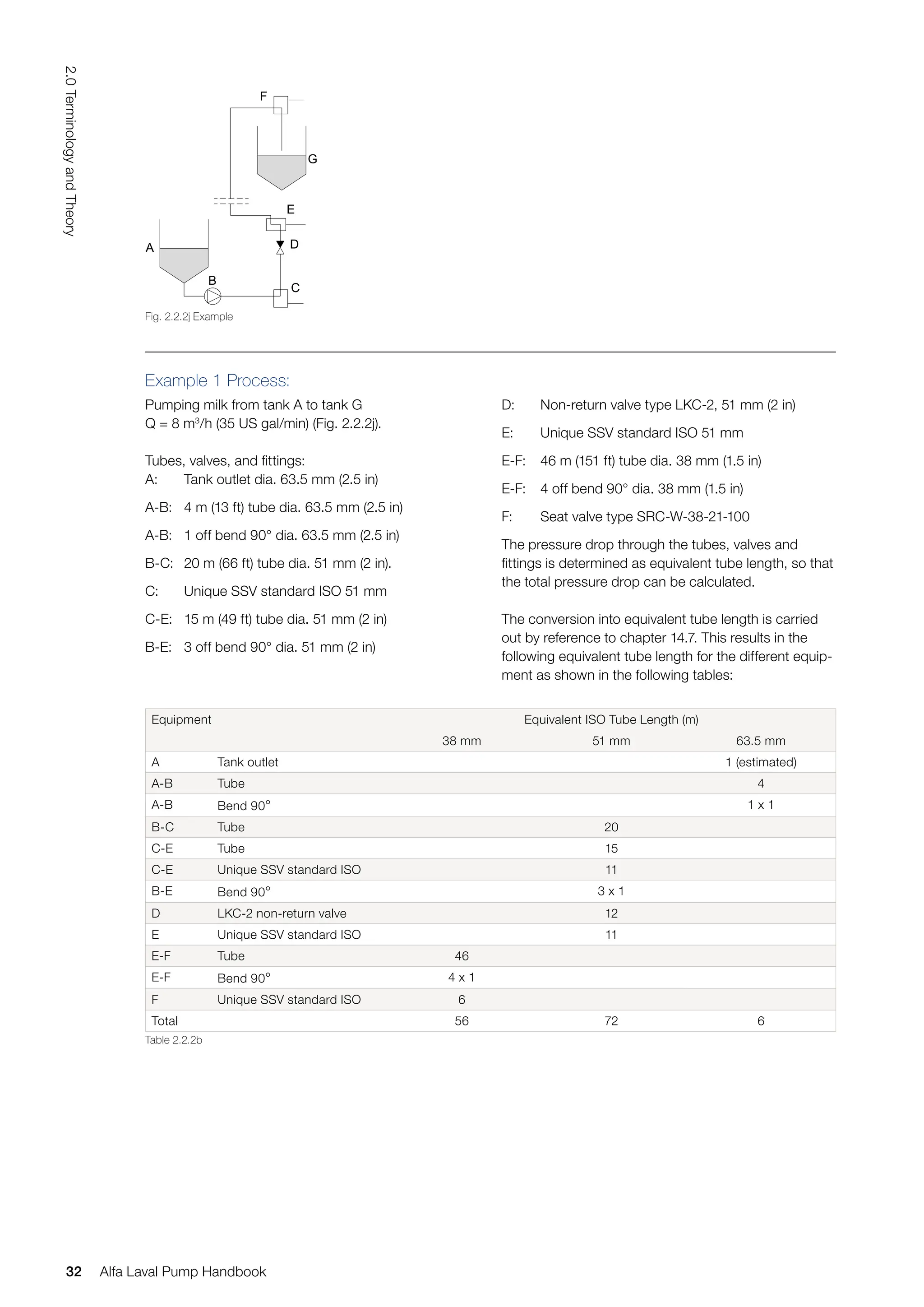
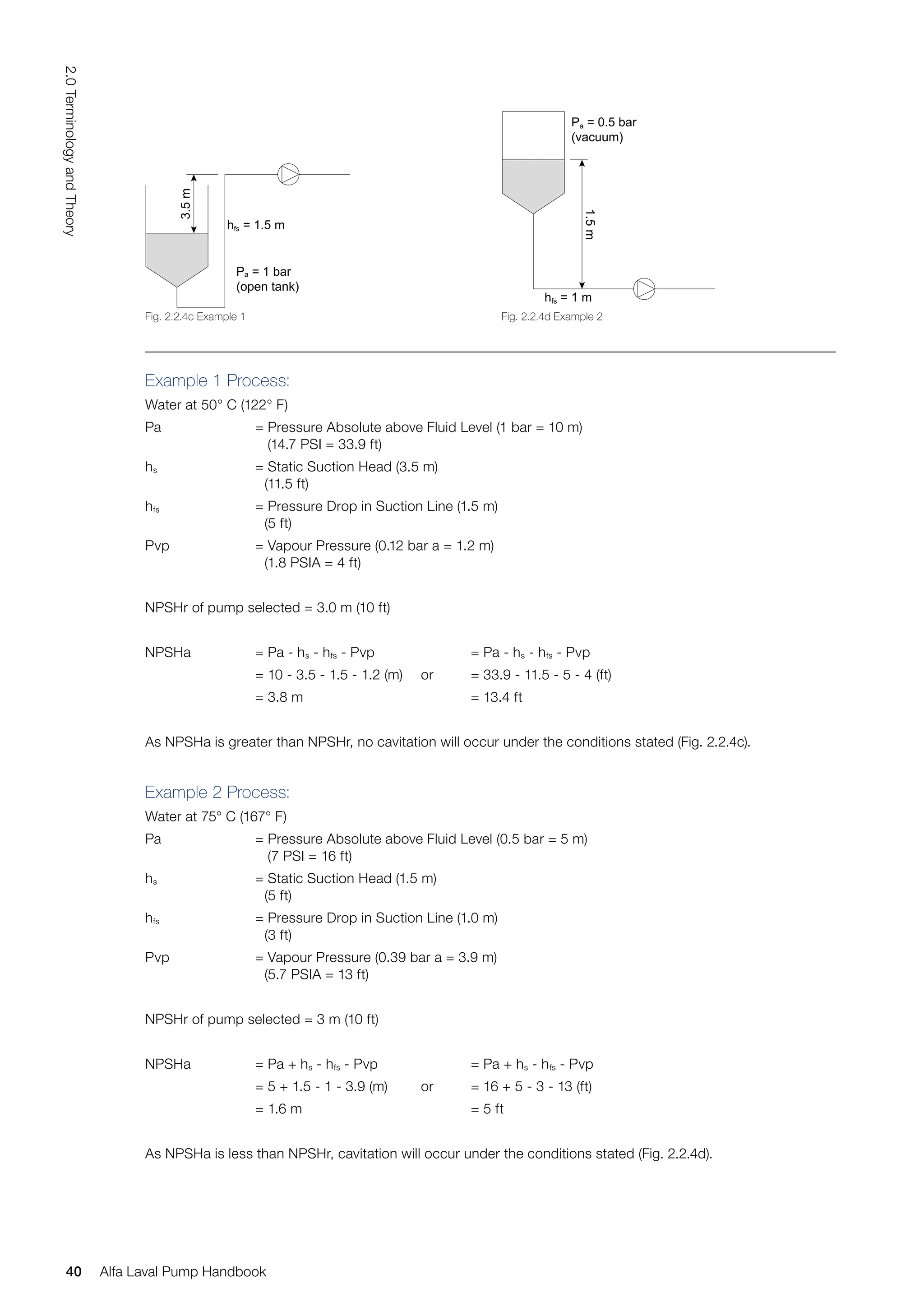
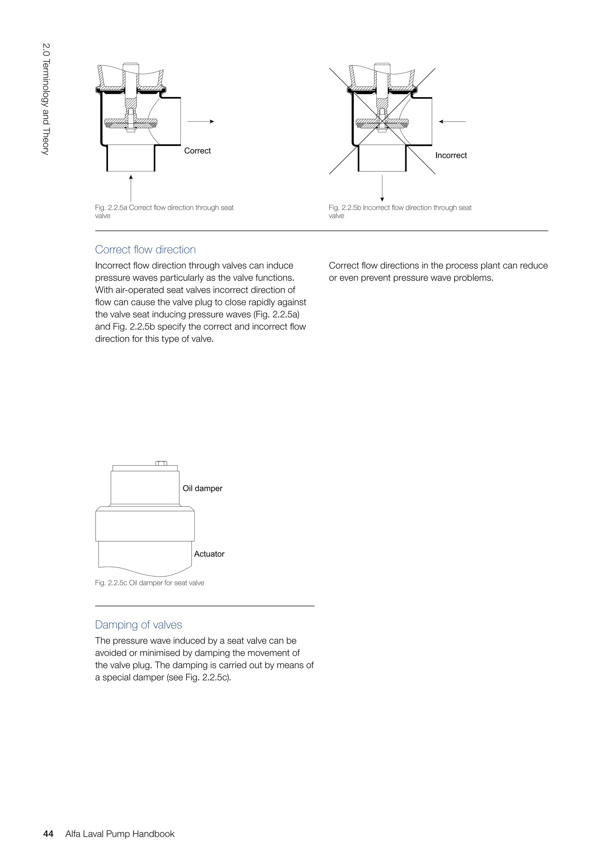
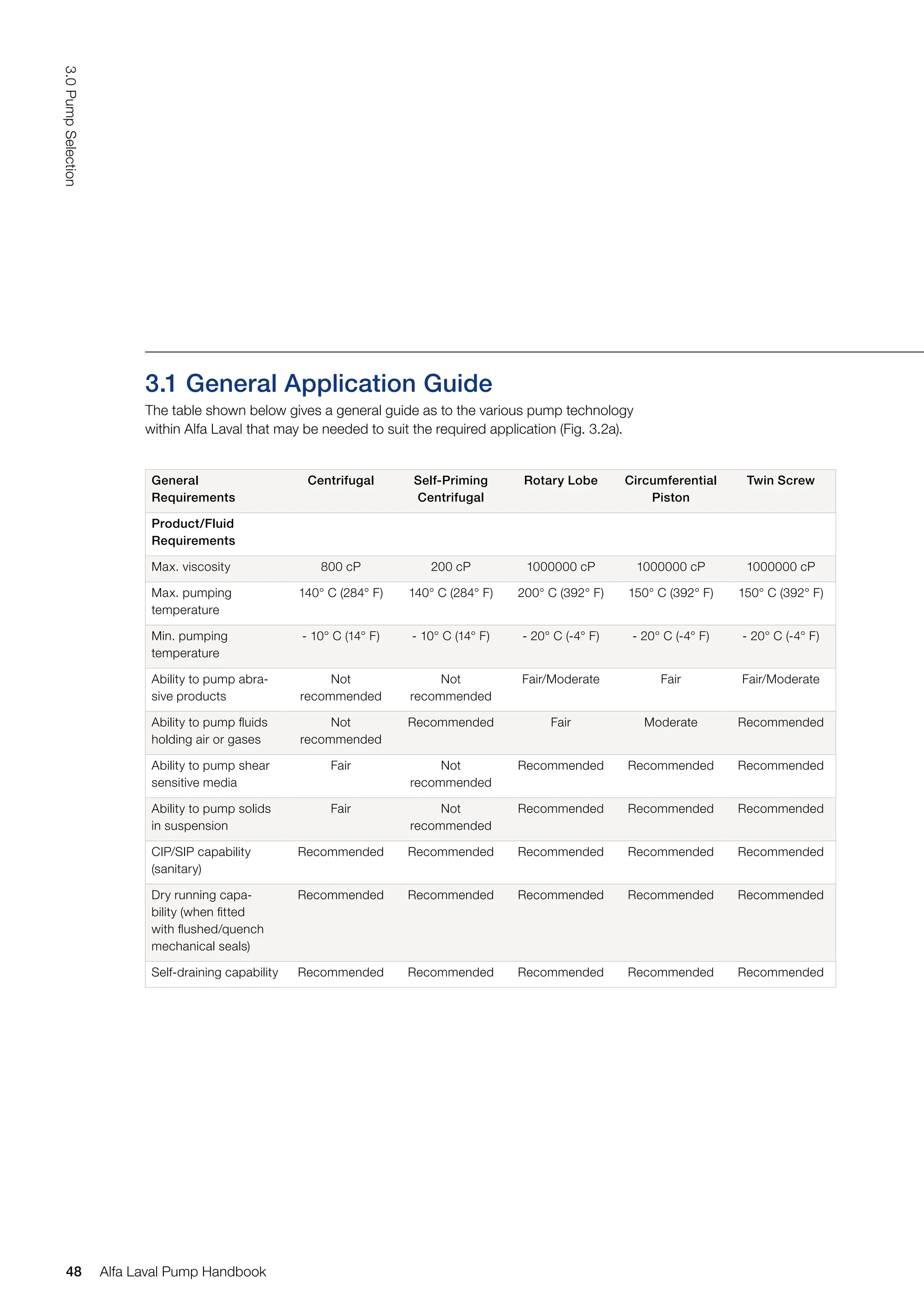
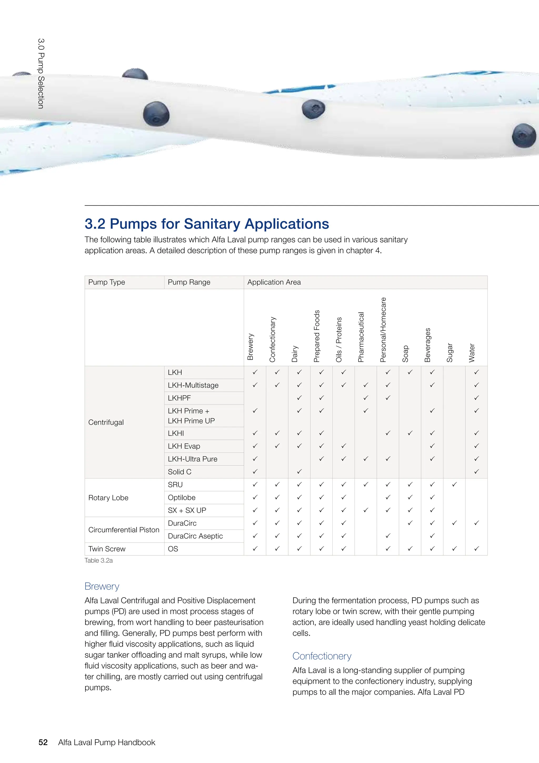
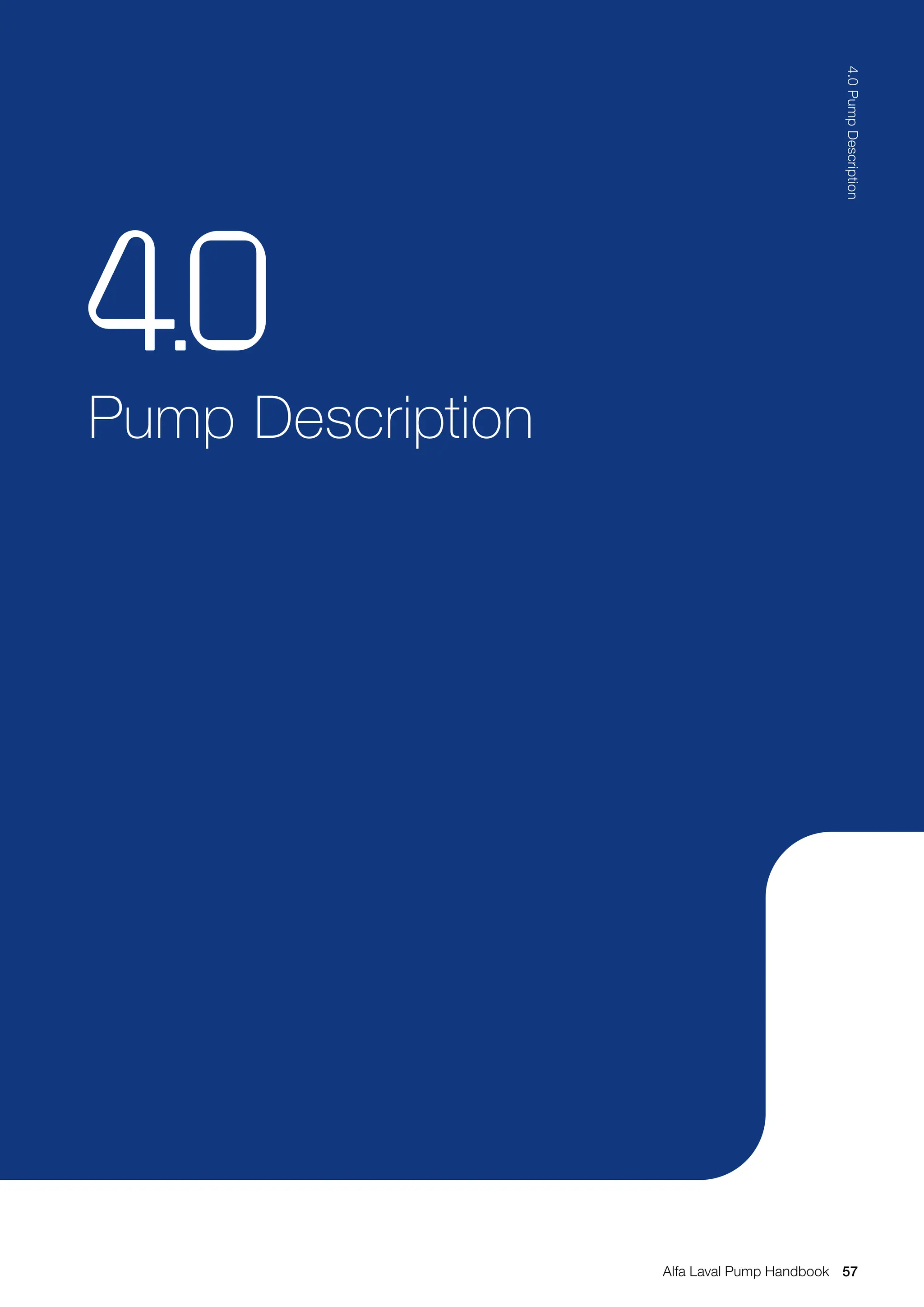
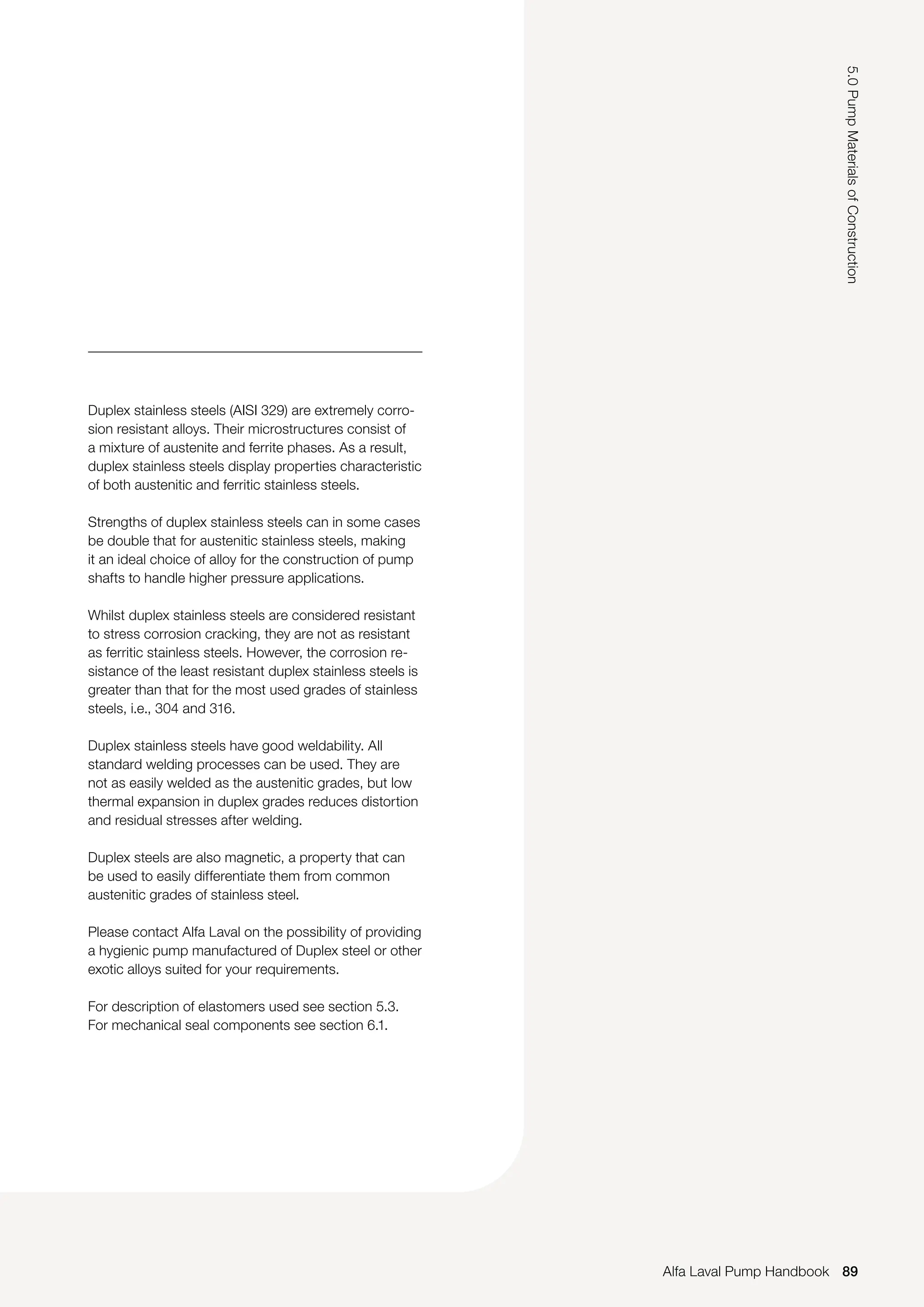
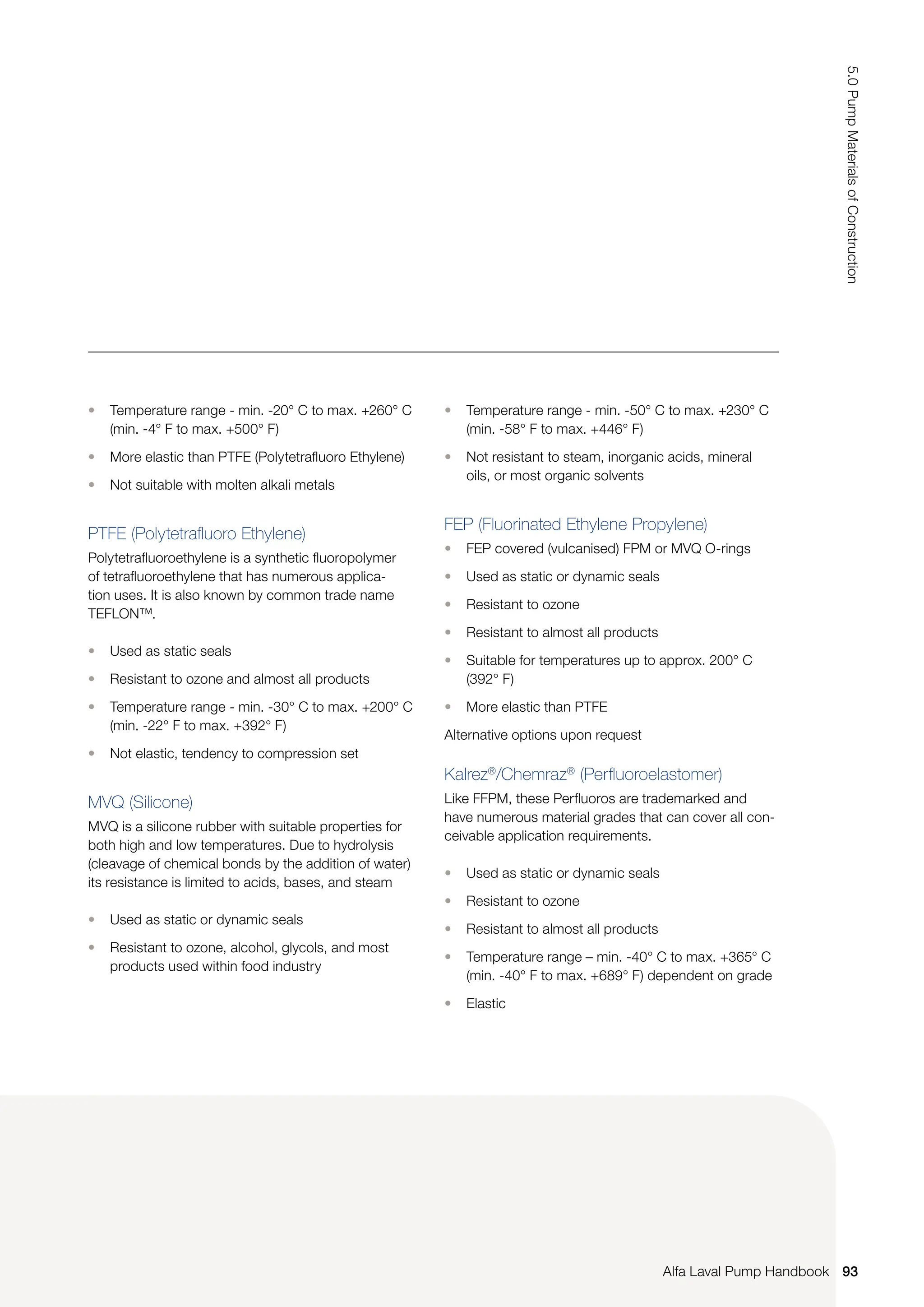
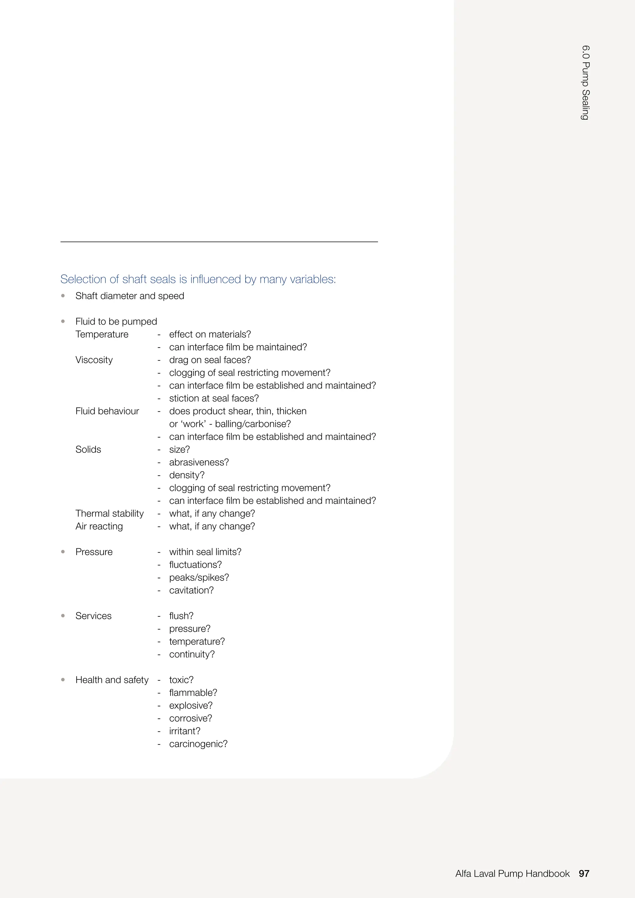
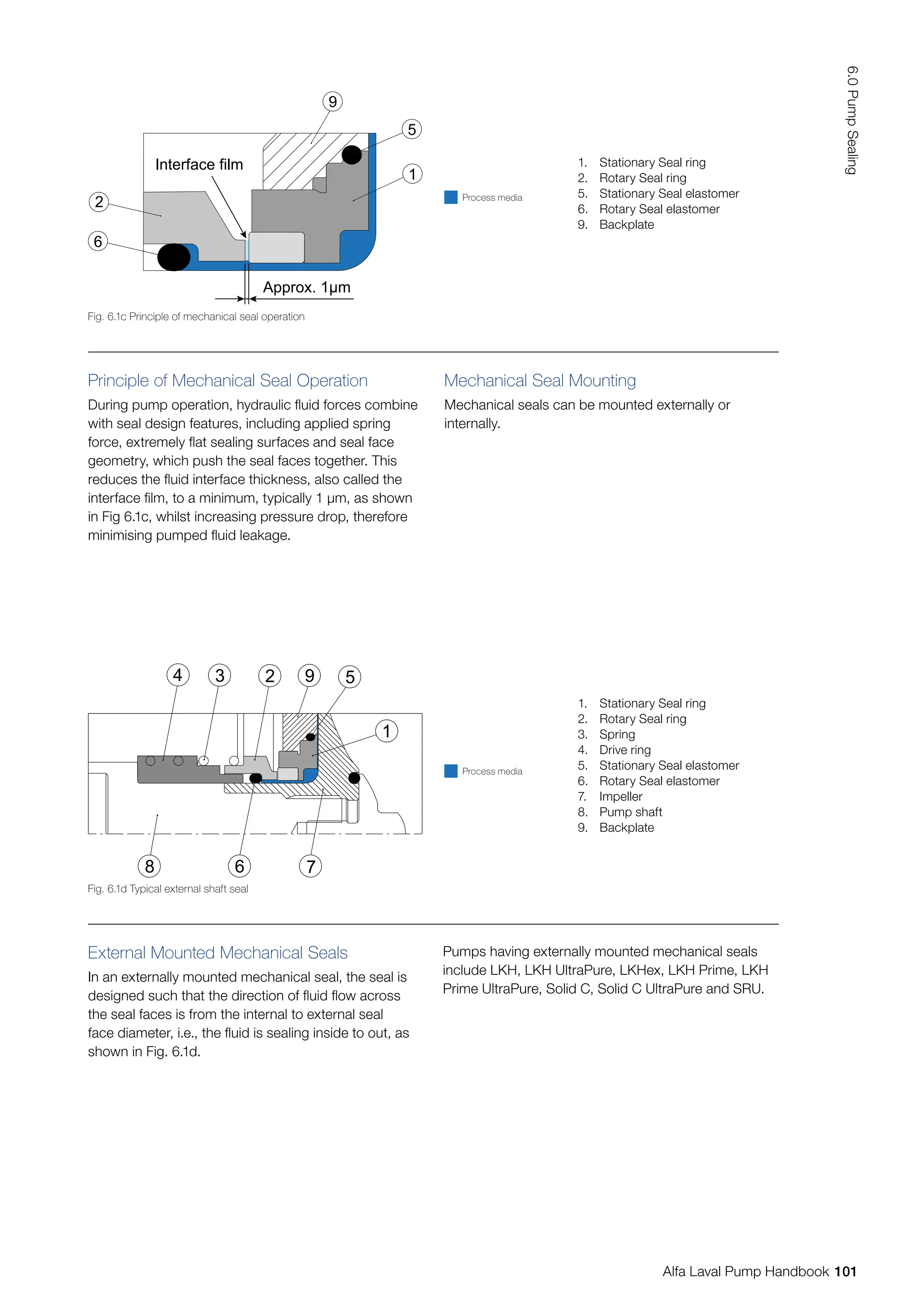
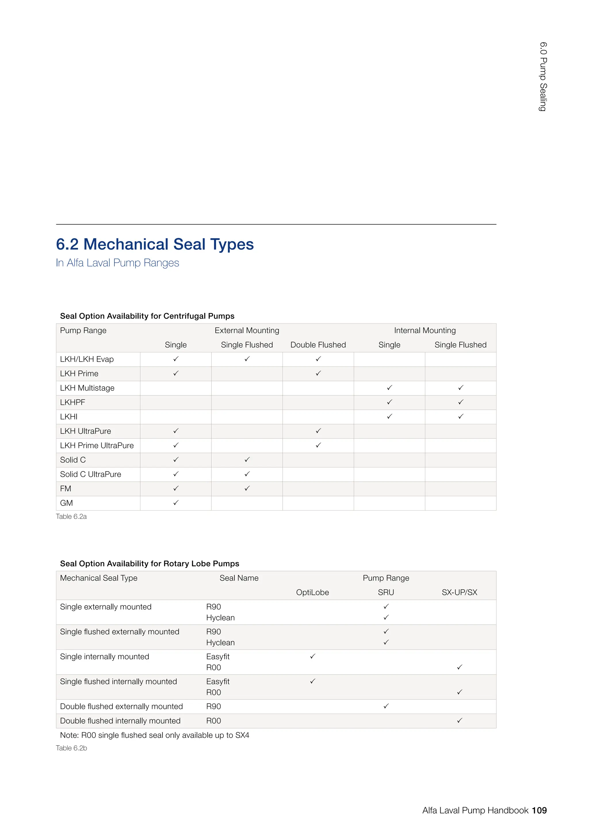
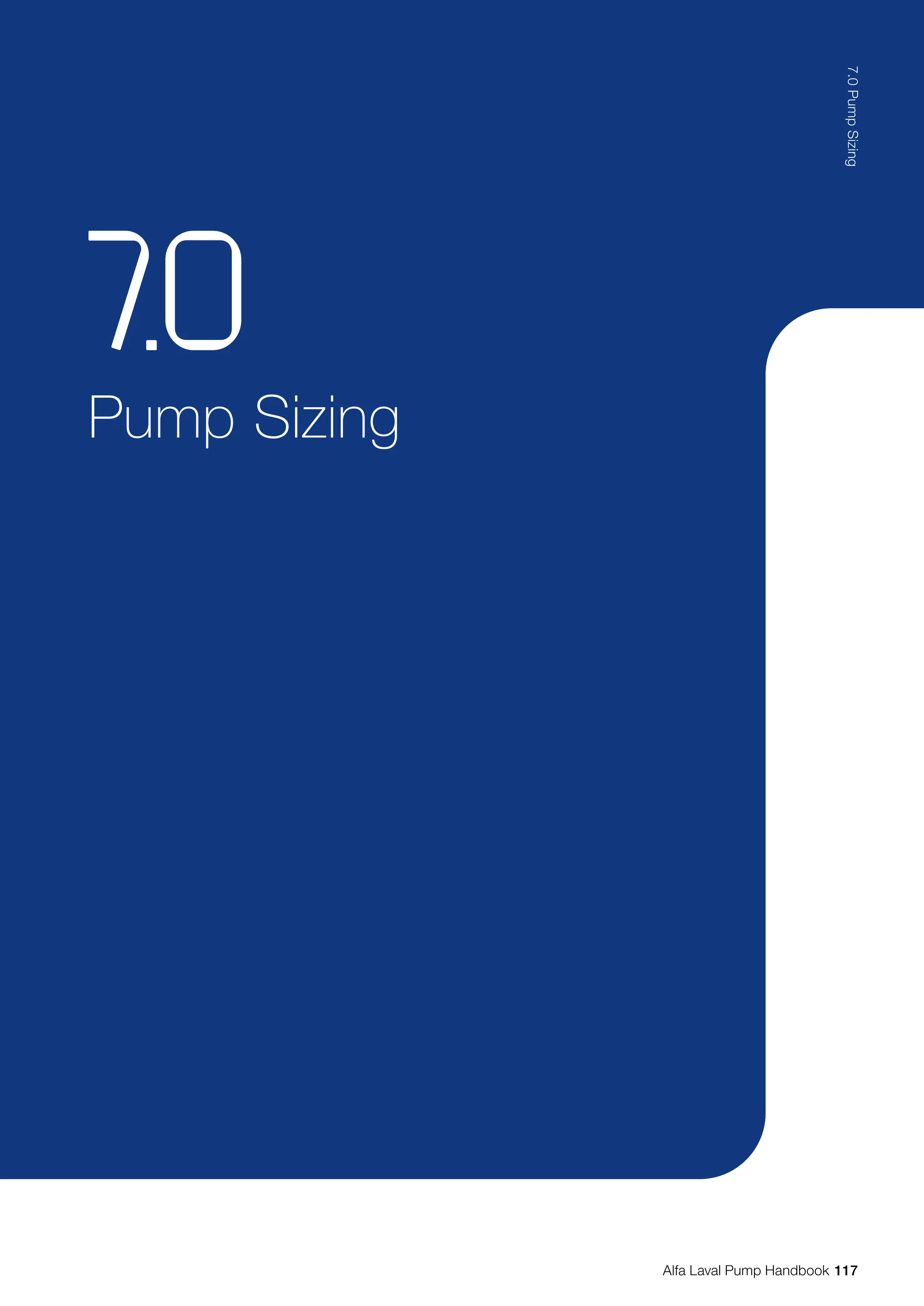
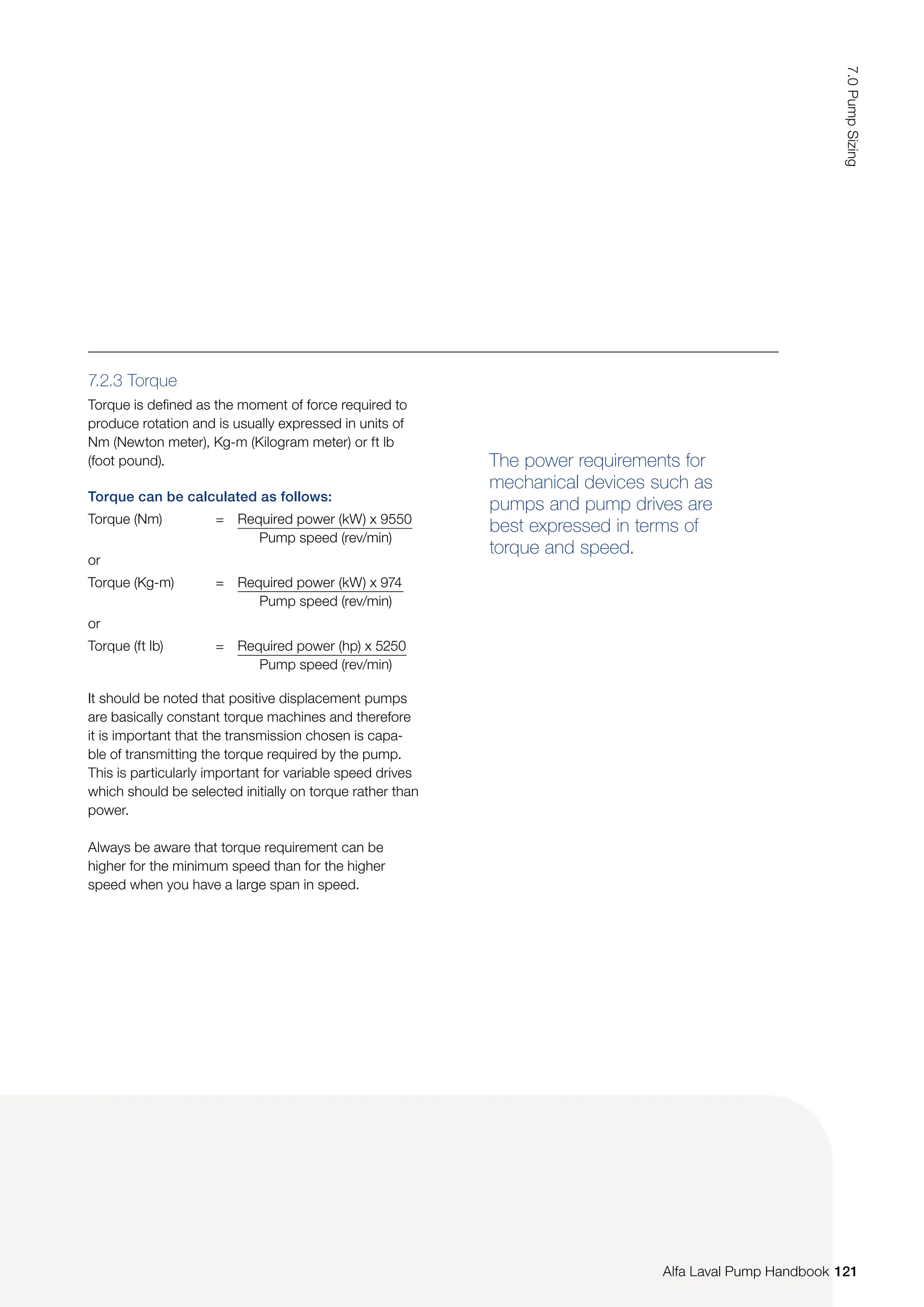
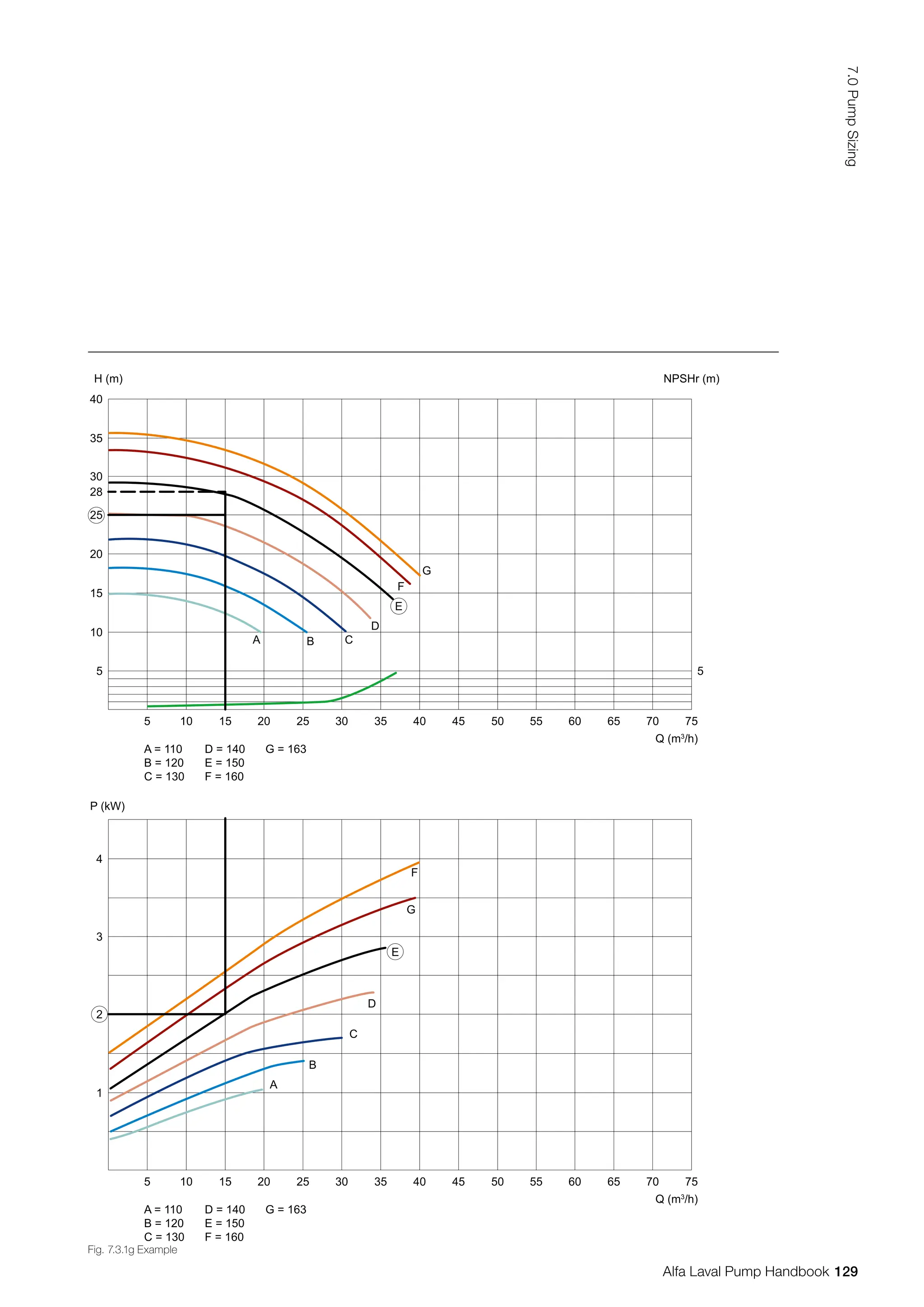
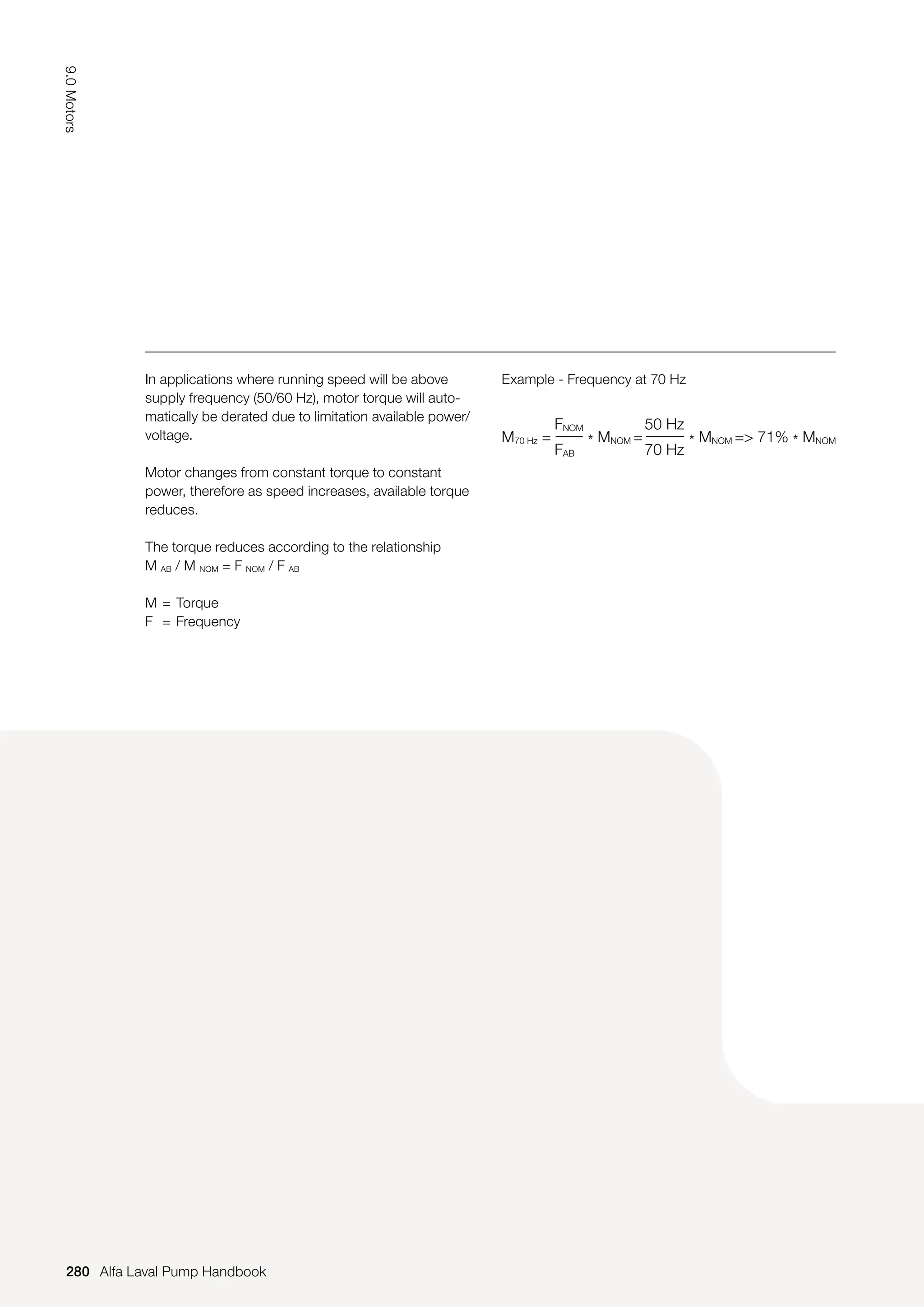
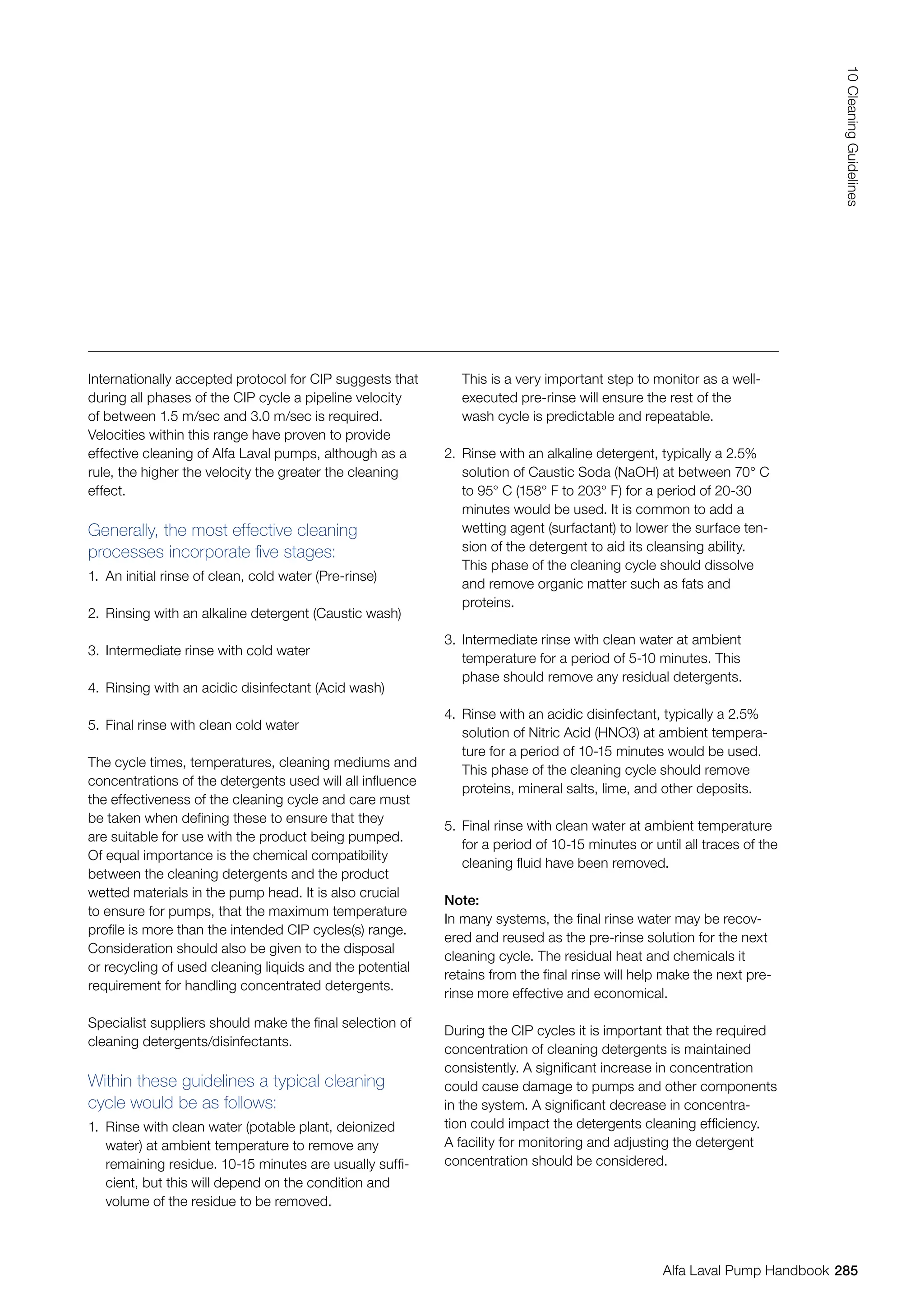
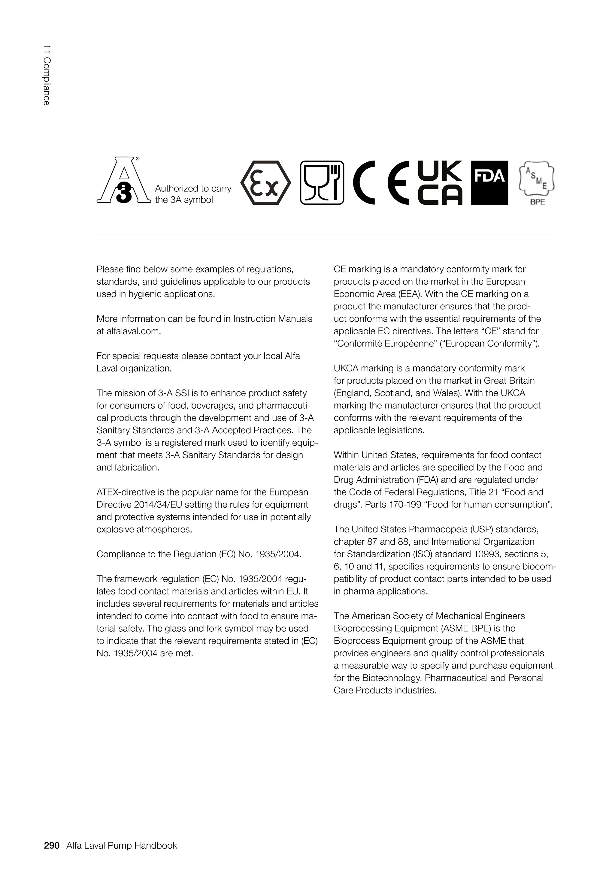
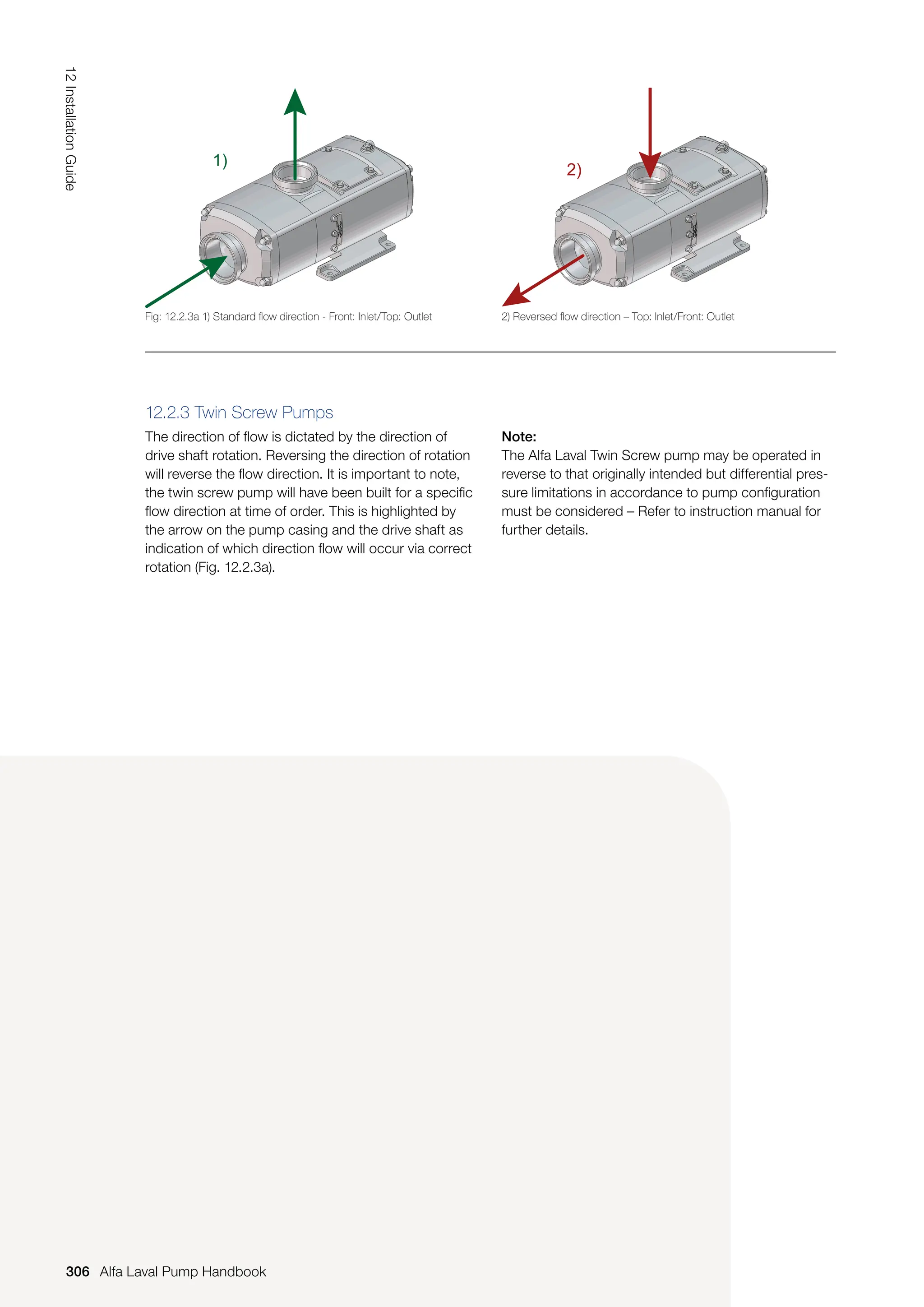
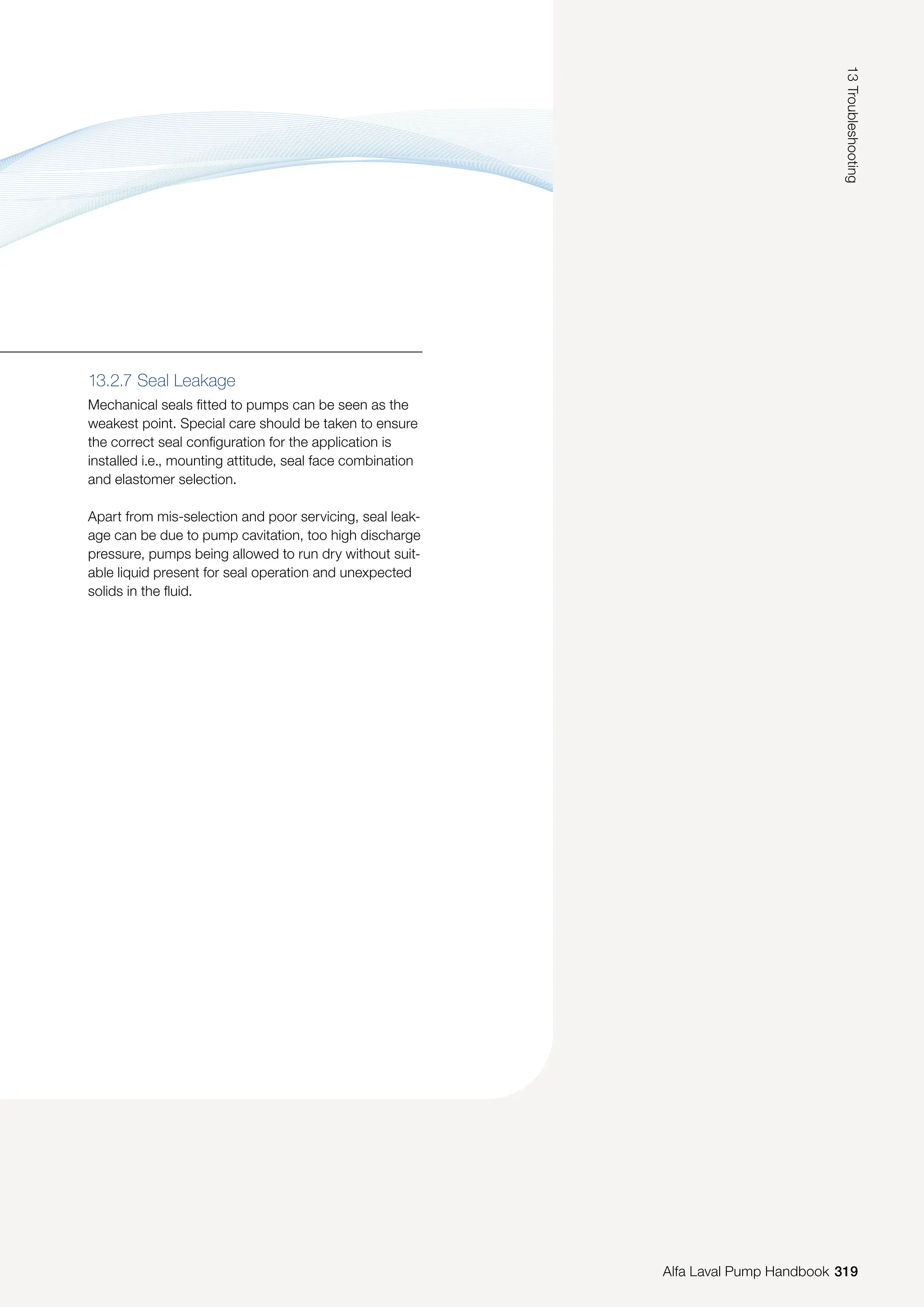
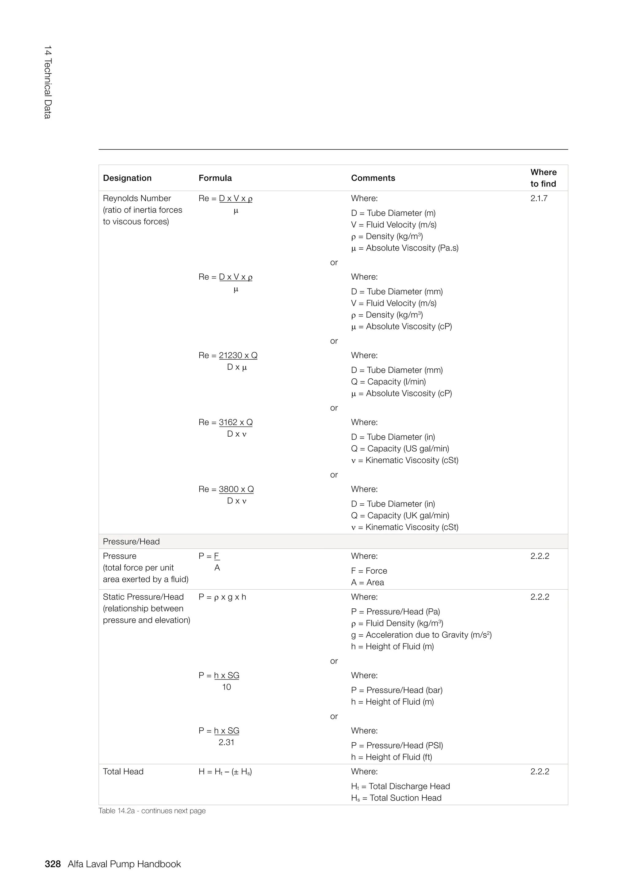
![With a self-cooled (TEFC) motor on a supply frequency
of 50 Hz, there is a constant torque between 50 - 25
Hz (50% or 2:1) meaning no derating in torque output.
Below 25 Hz, the torque output is derated due to the
slower running speed of the integrated fan, in order
to dissipate the additional heat generated (see Fig.
9.11.3b).
1.05
1.00
0.95
0.90
0.85
0.80
0.75
0.70
0.65
0.60
0.55
0.50
0.45
0.40
0 0.1
A = Slower the speed, the greater the torque derates
B = Constant Torque Range (No derating)
C = Constant flux. Constant V/f. 50 Hz Supply
D = Note:
1.0 represents 100%
Frequency output: 50 or 60 Hz
0.5 would represent 50%; 25 or 30 Hz
E = 25 Hz
F = 50 Hz
A
D
B
C
E F
0.2 0.3 0.4 0.5 0.6 0.7 0.8 0.9 1.2 1.3 1.4 1.5 1.6 1.7 1.8 1.9
1.0
Torque derating for self cooling motors
[f/fn] - Operating frequency (p.u.)
[T
R
]
—
Torque
derating
factor
(p.u.)
2.0
1.1 2.1
Fig. 9.11.3b Above shows the relationship of torque to frequency
277
9.0
Motors
Alfa Laval Pump Handbook
Alfa Laval Pump Handbook](https://image.slidesharecdn.com/pump-handbook-2024-251113133245-895f754e/75/Alfa-Laval-Pump-Handbook-Second-Edition-2023-279-2048.jpg)
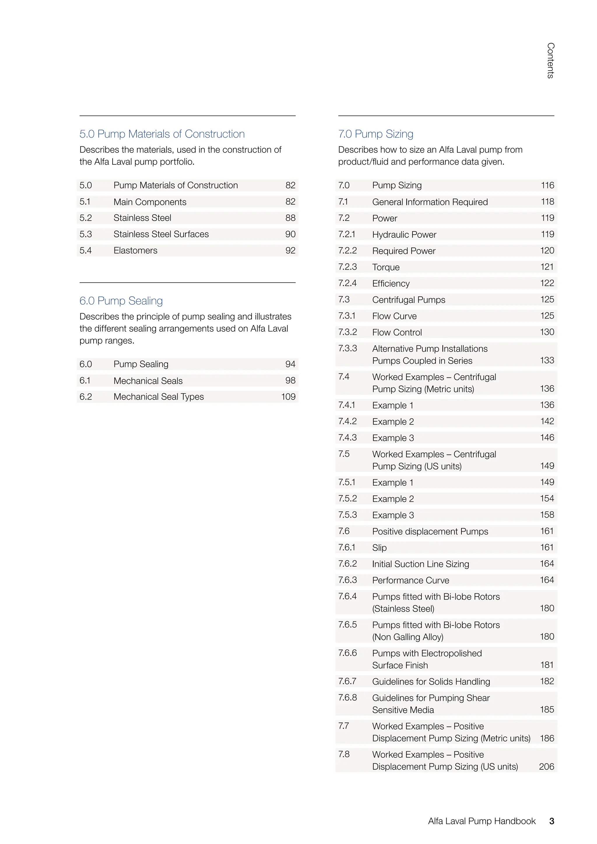
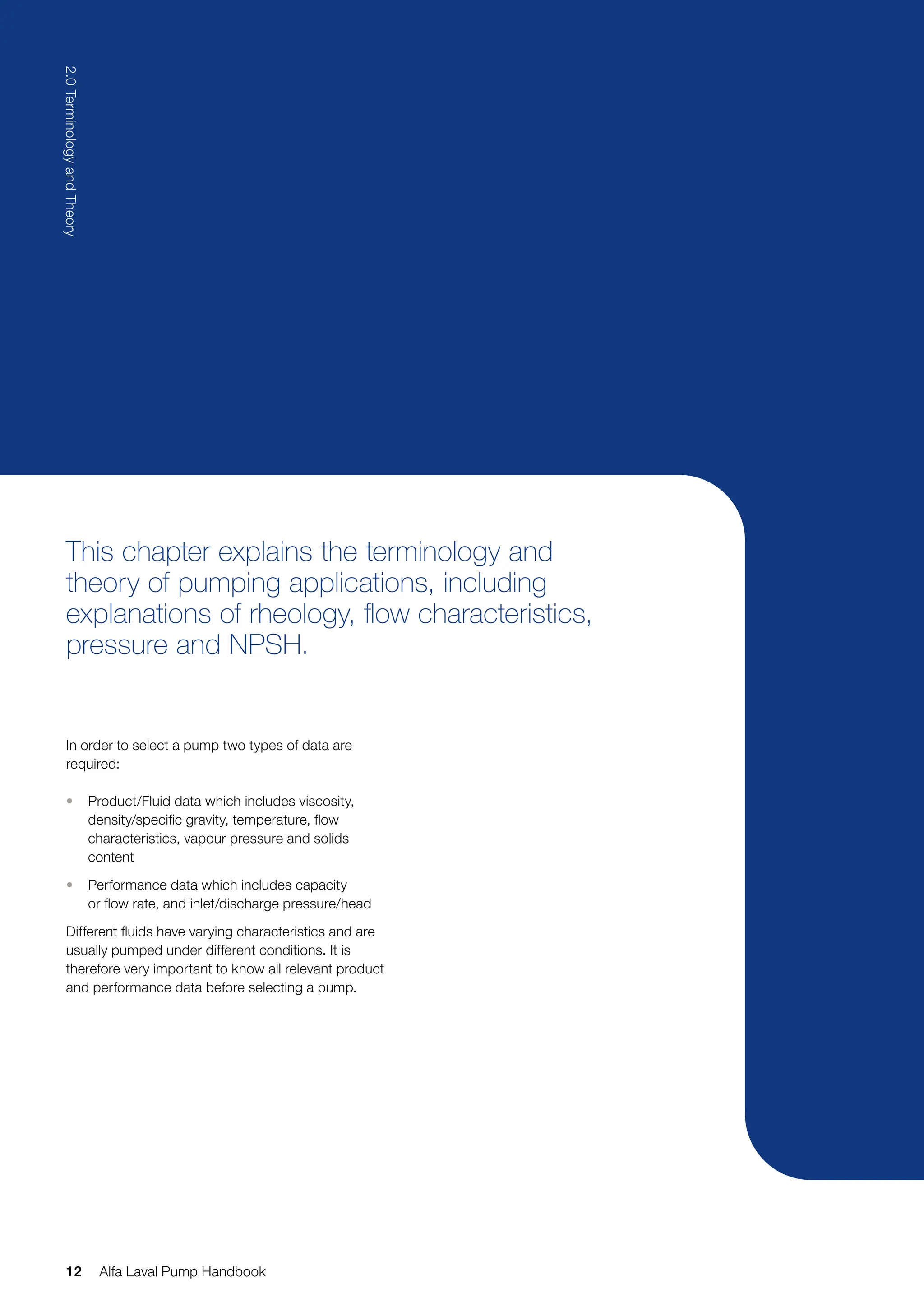
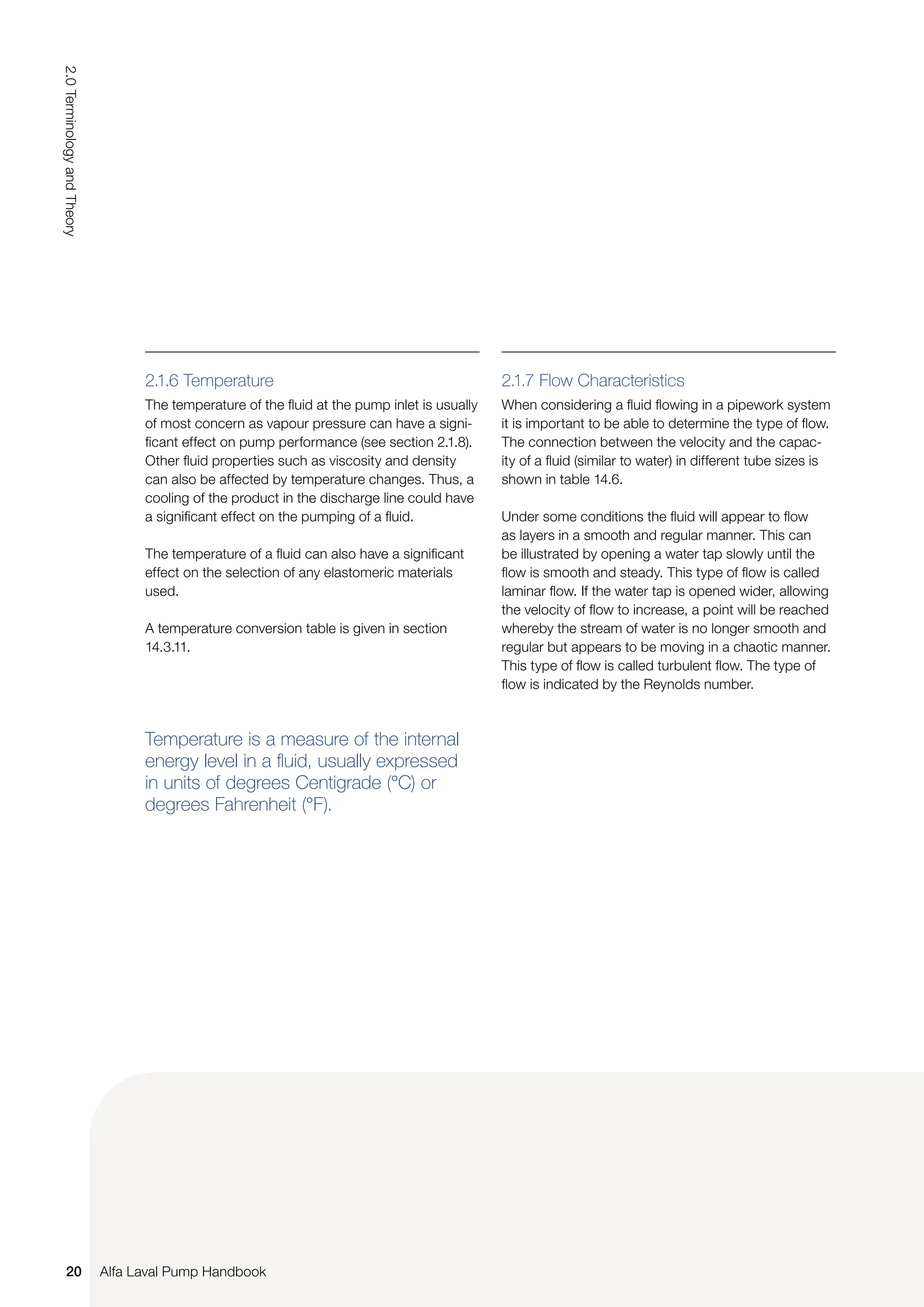
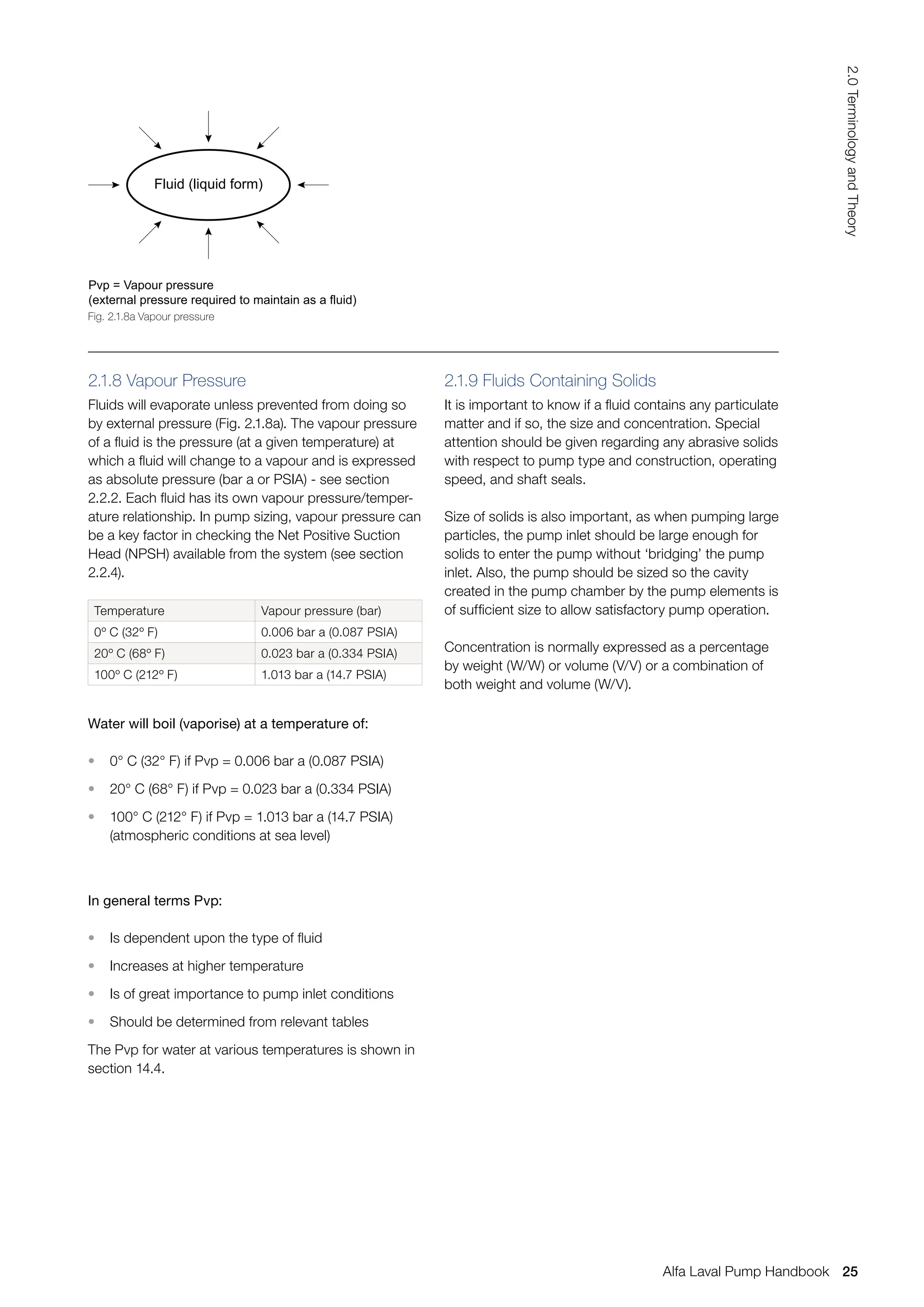
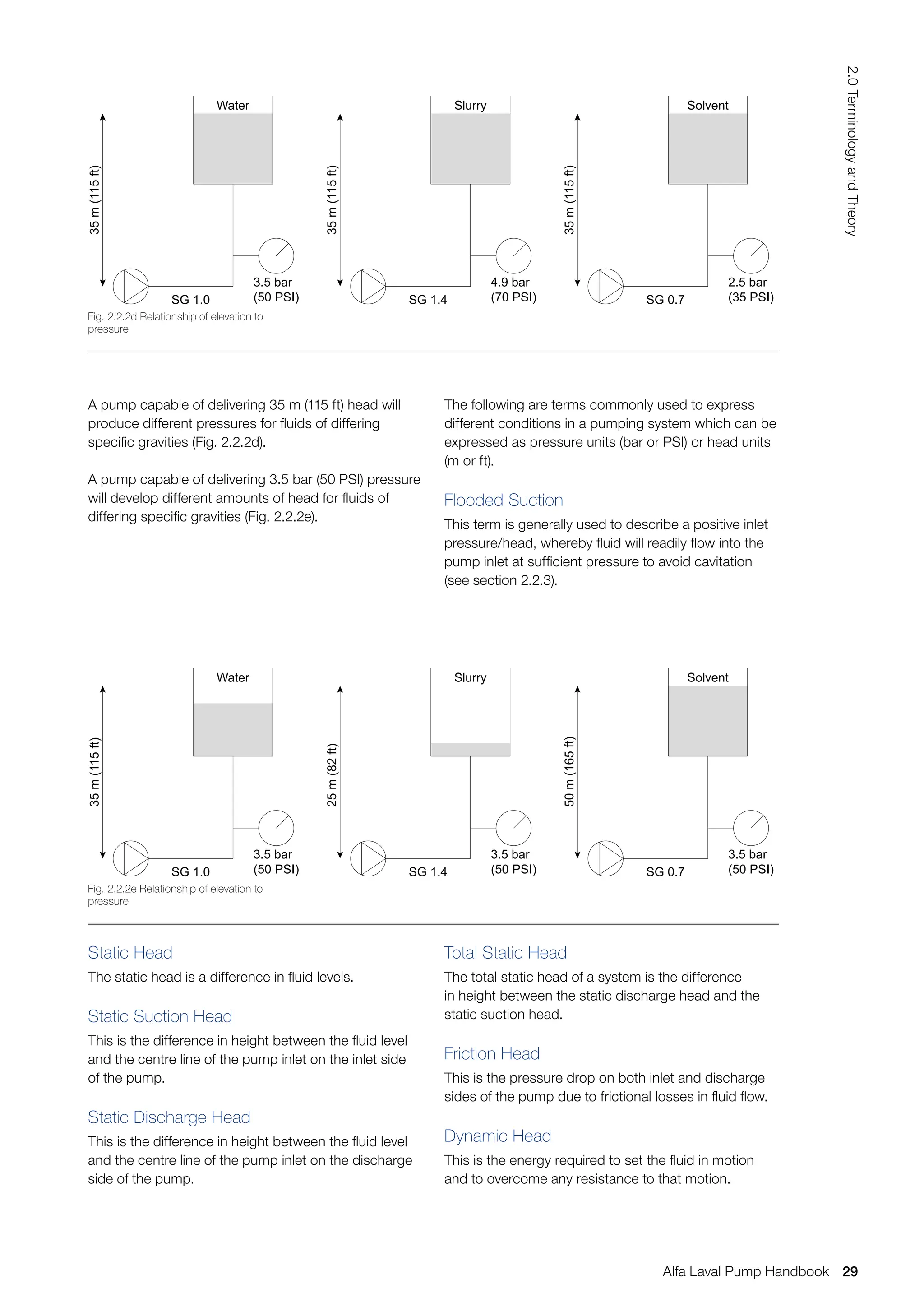
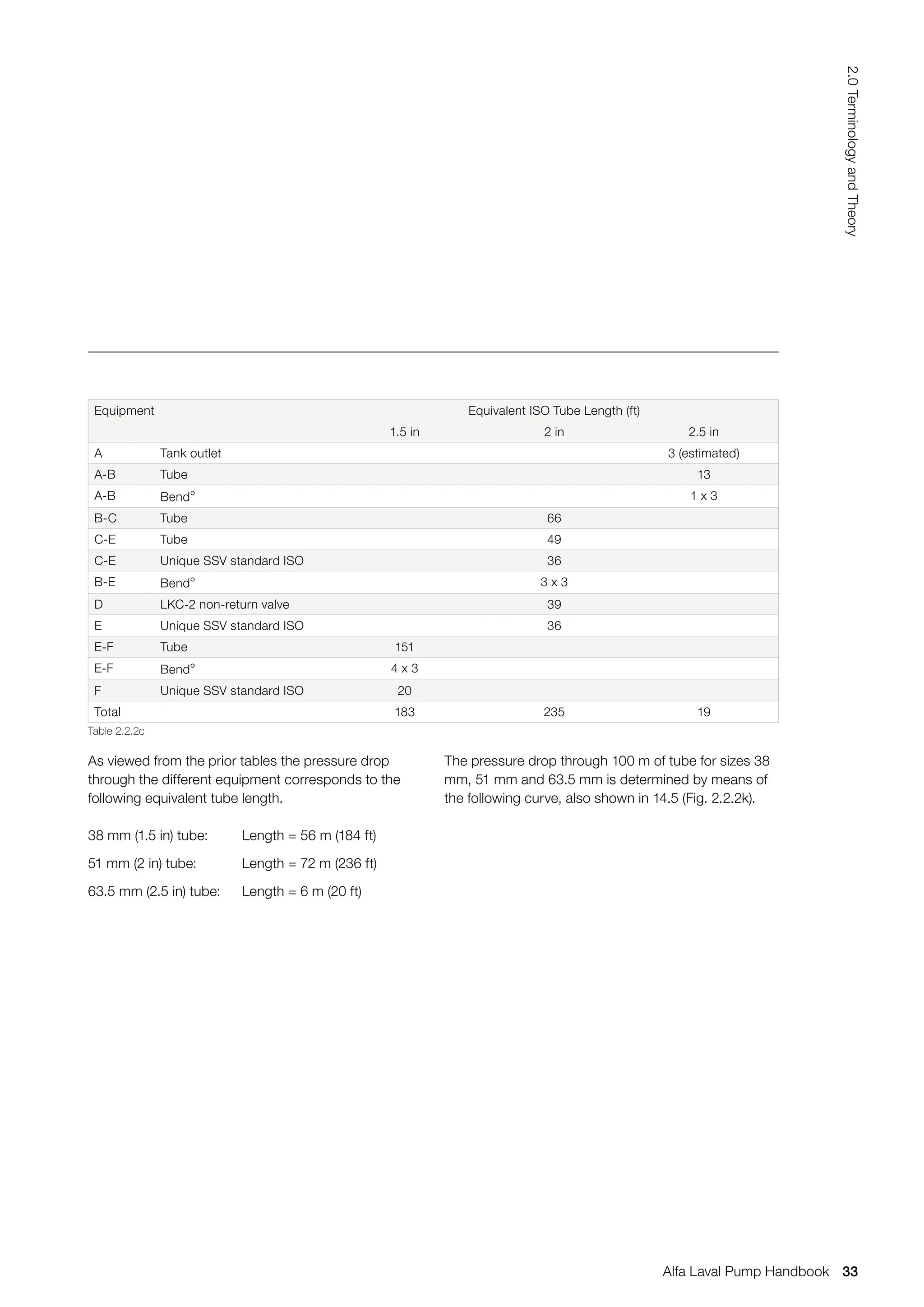
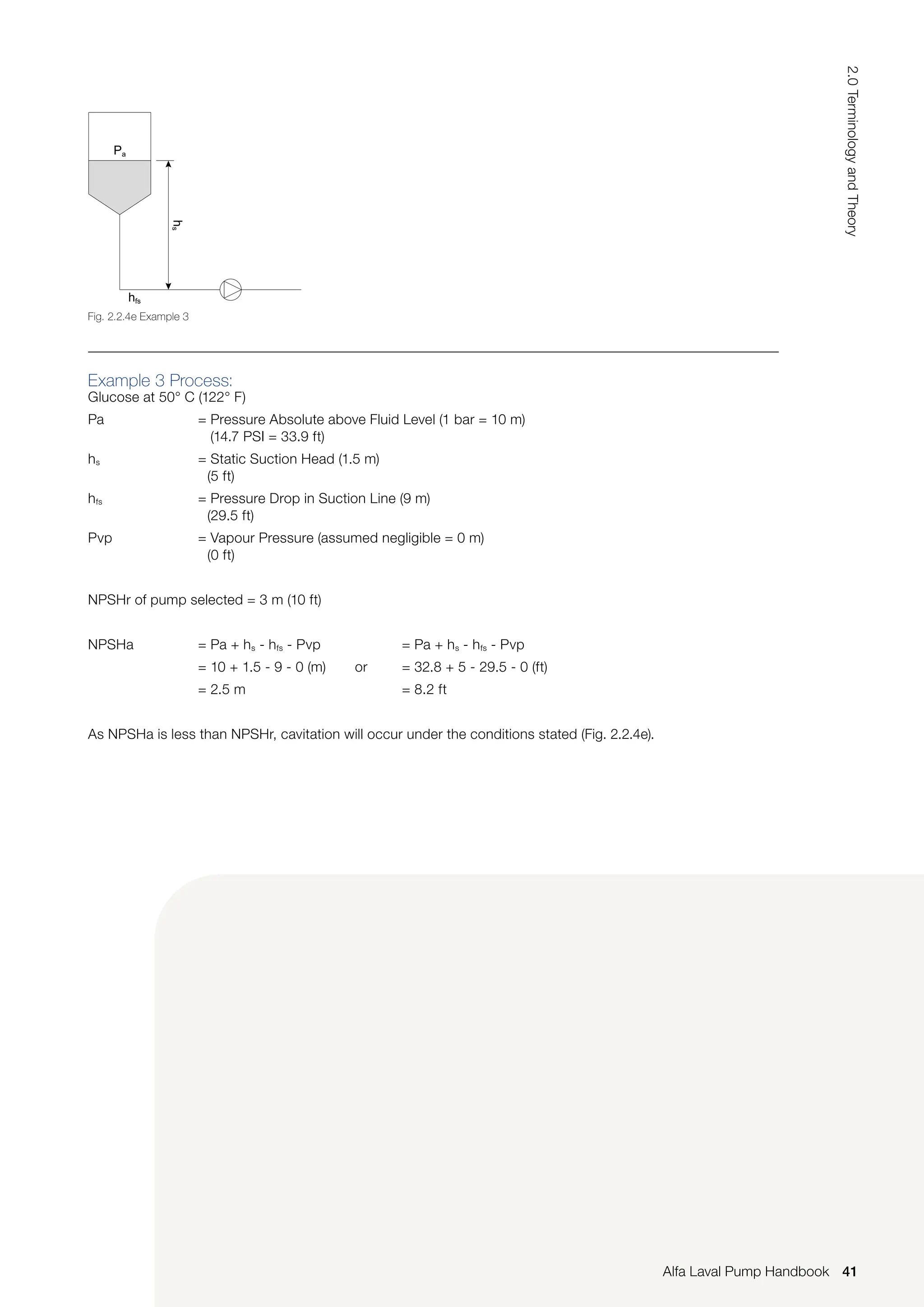
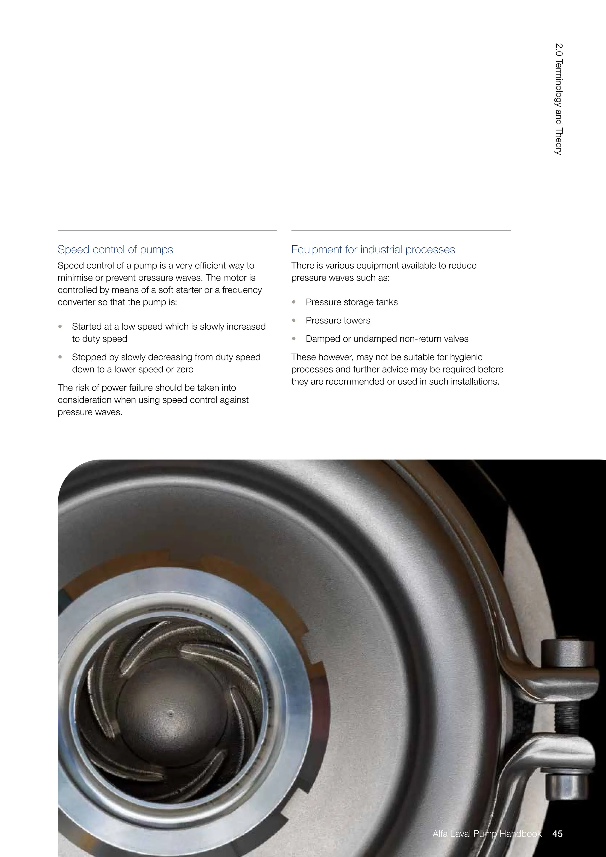
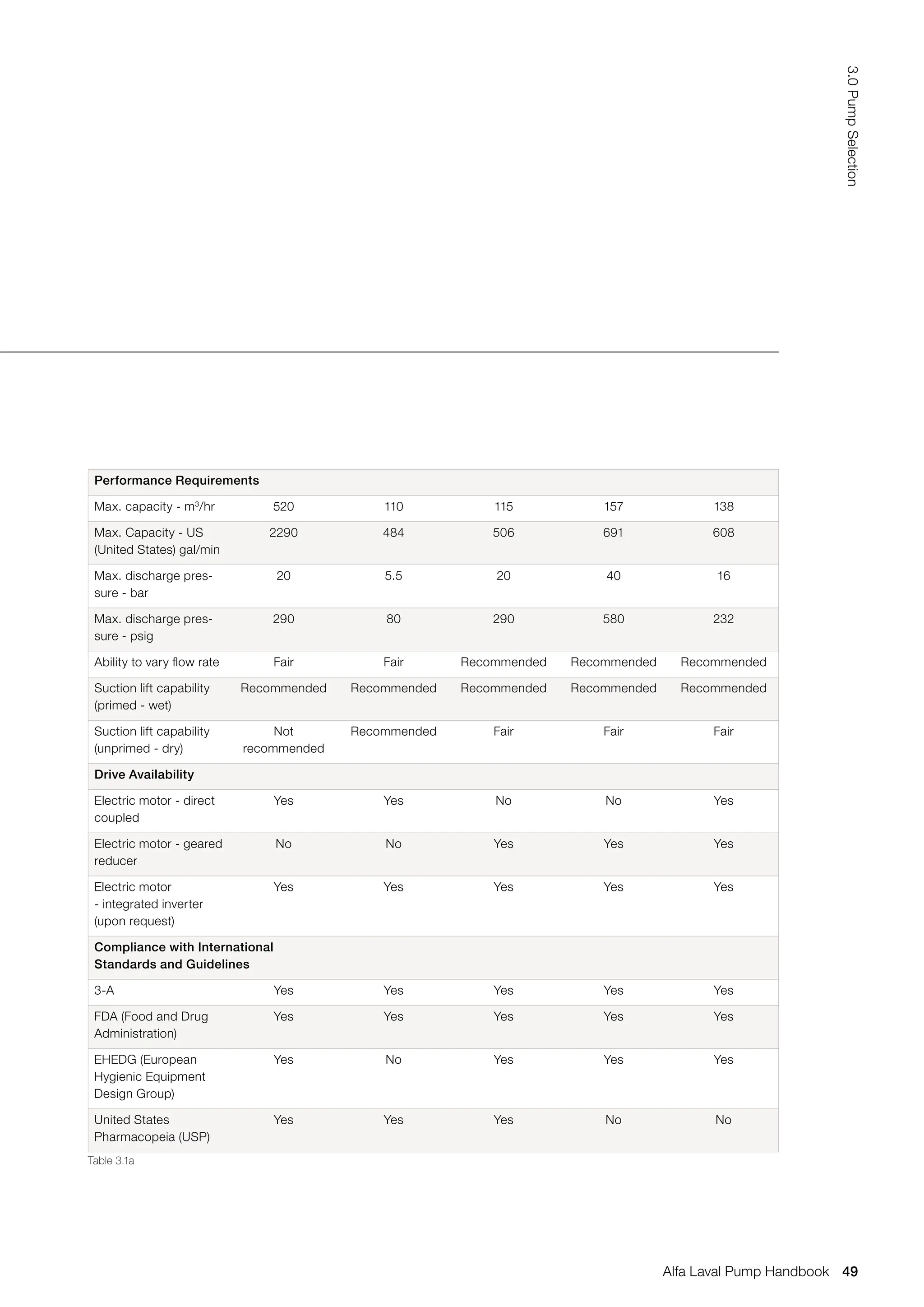
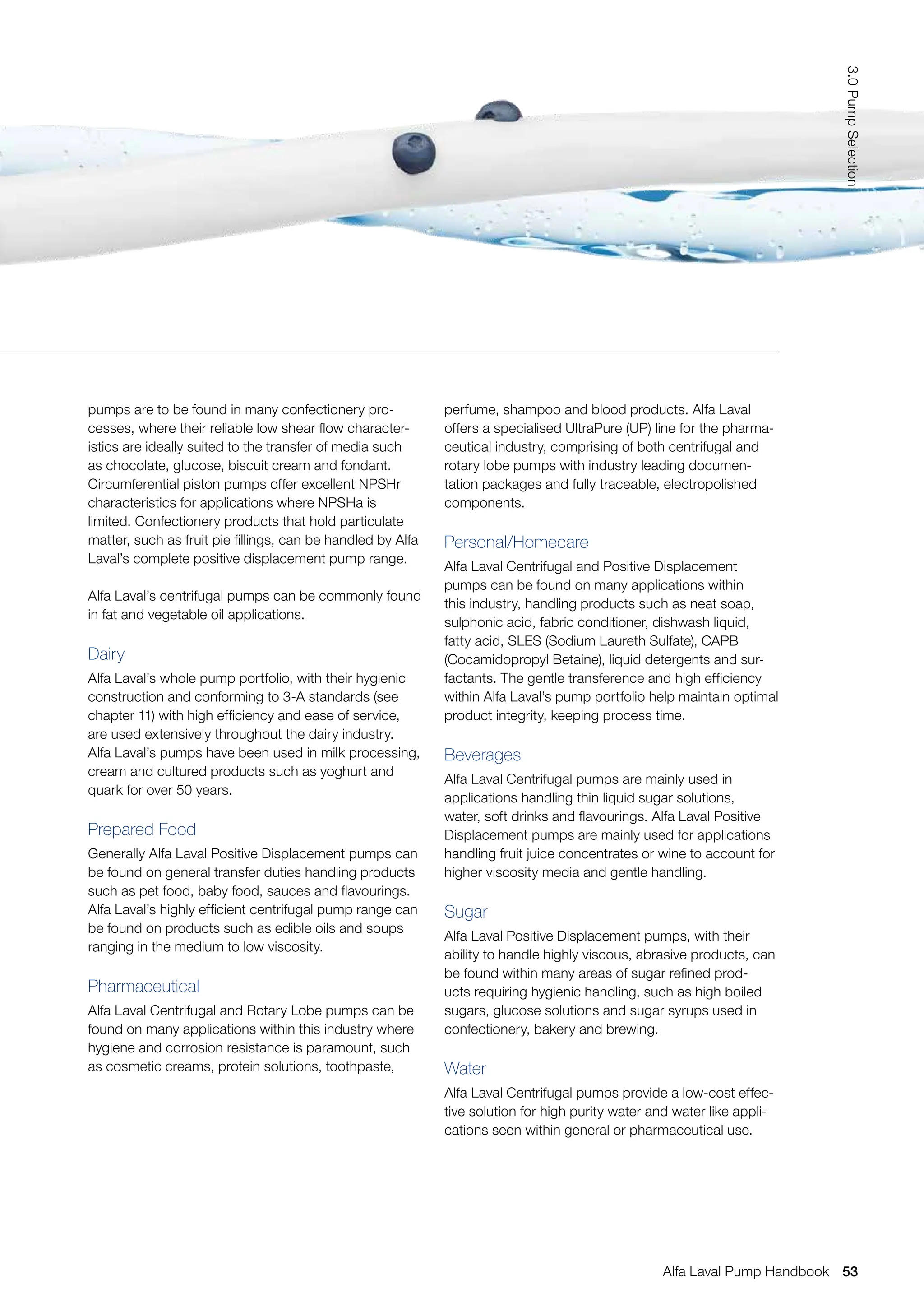
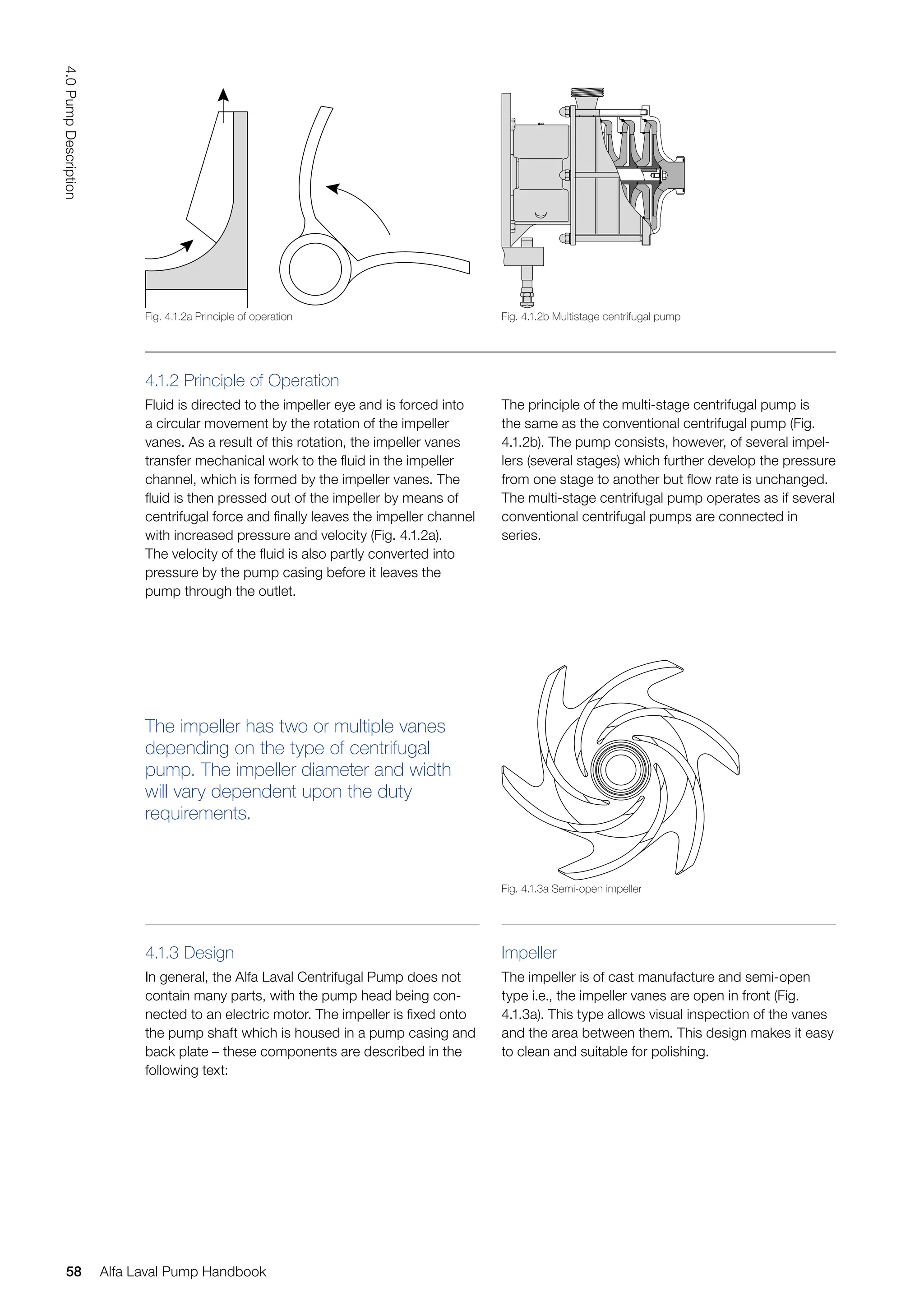
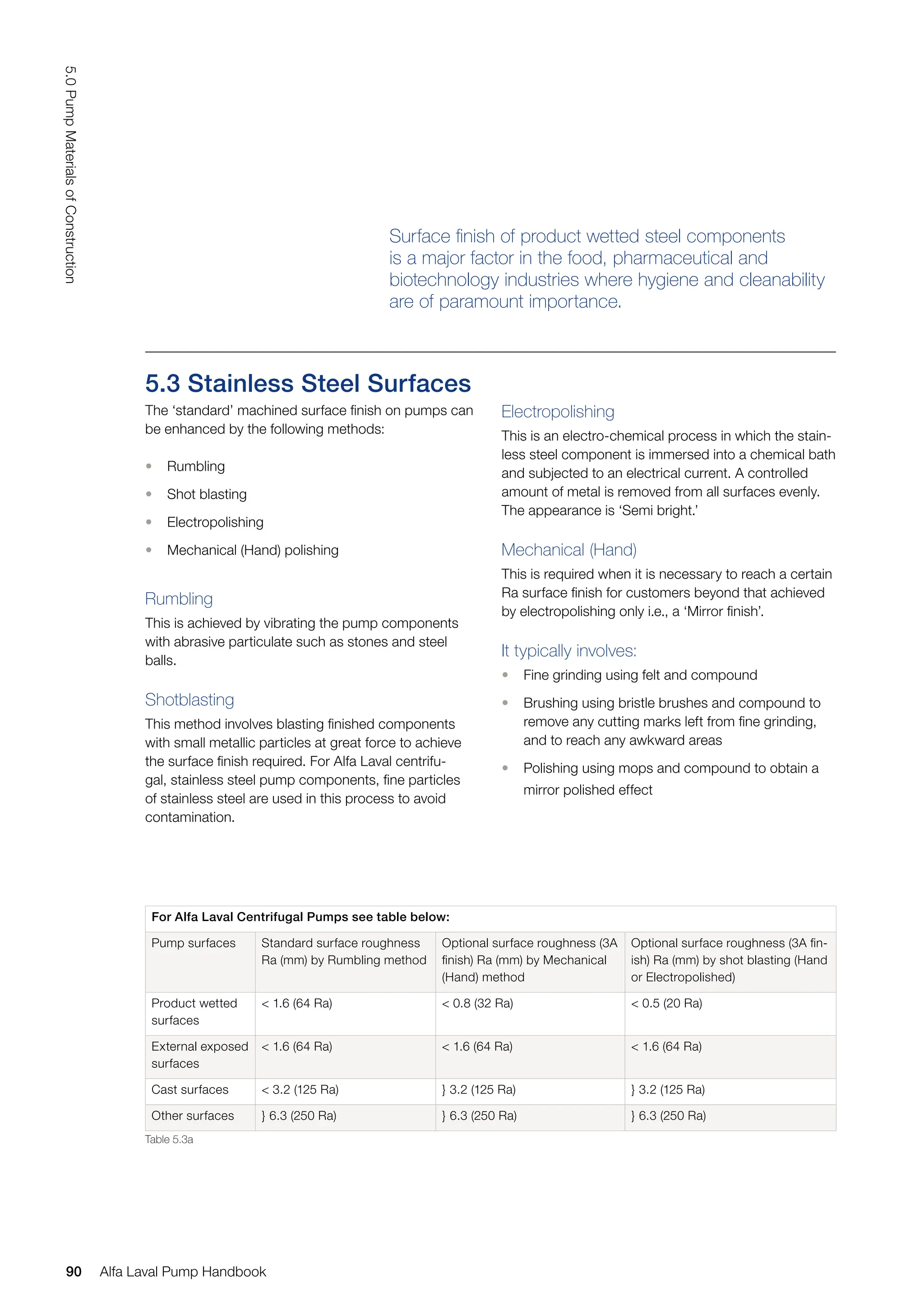
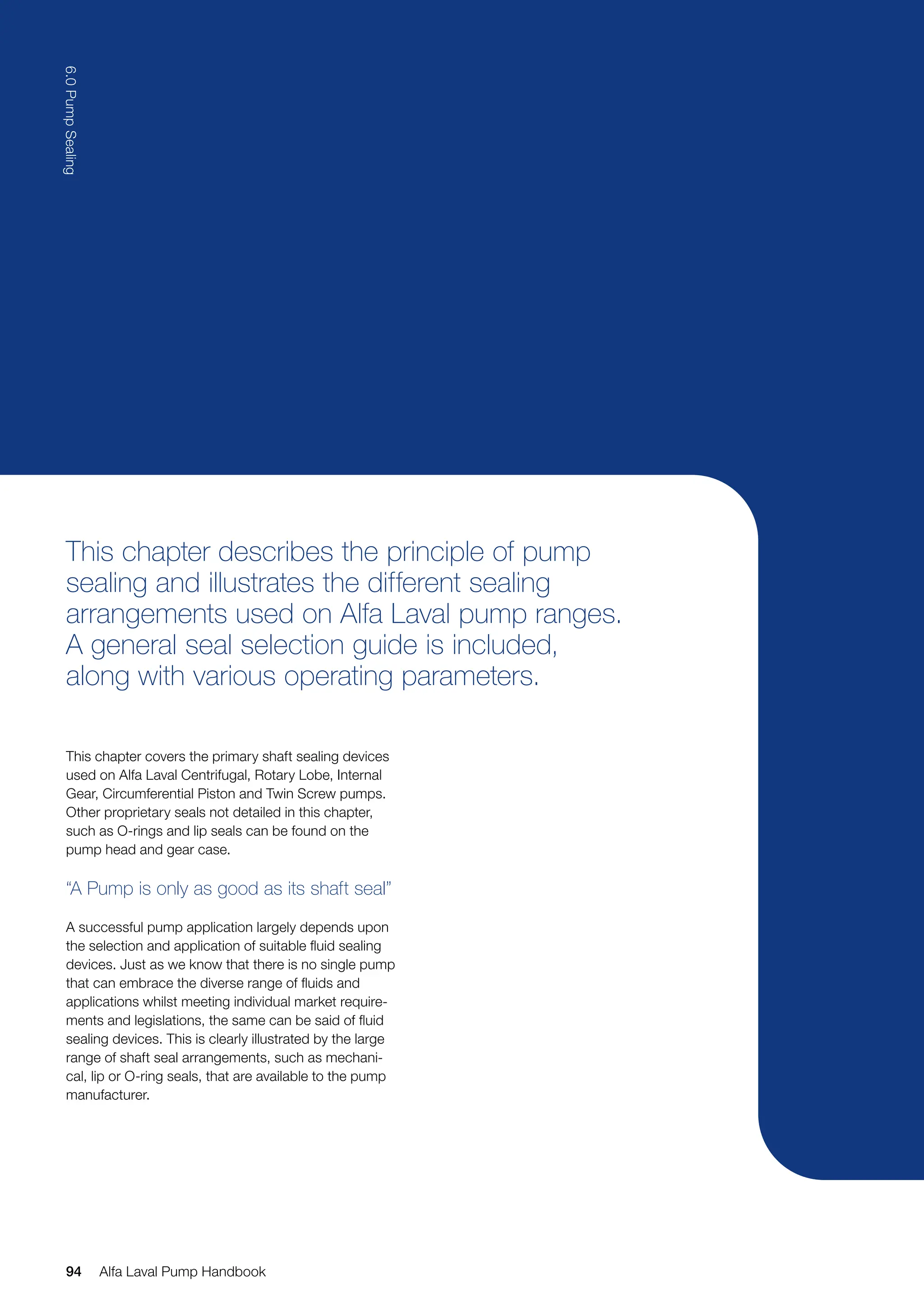
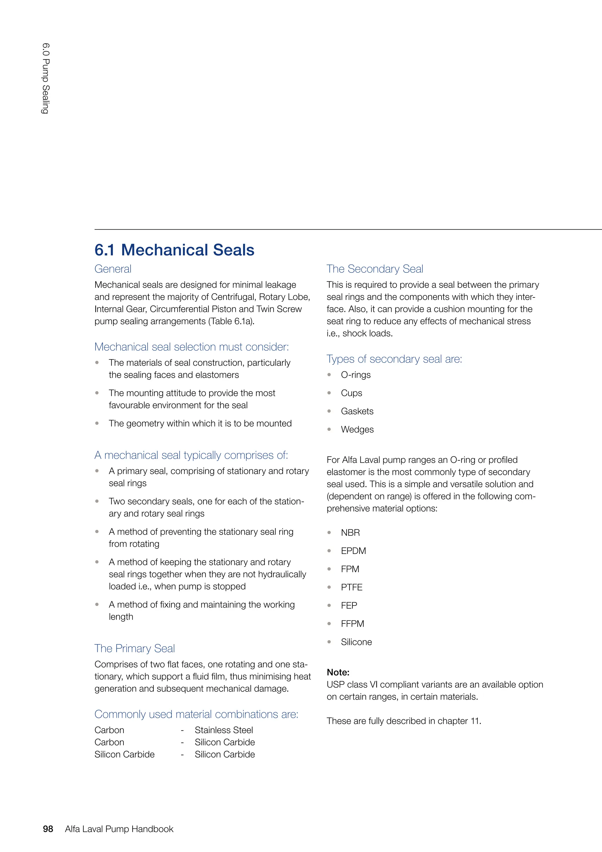
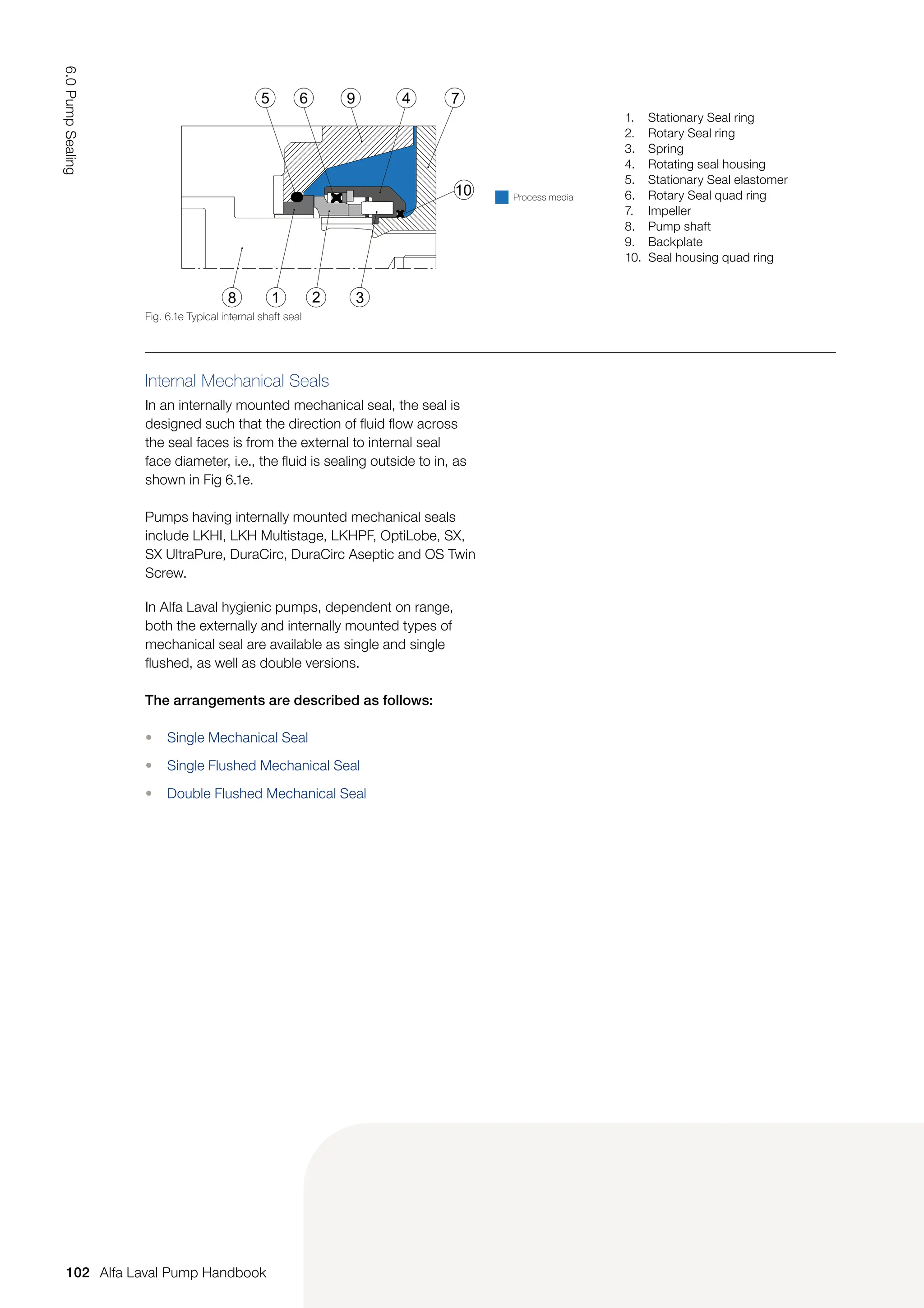
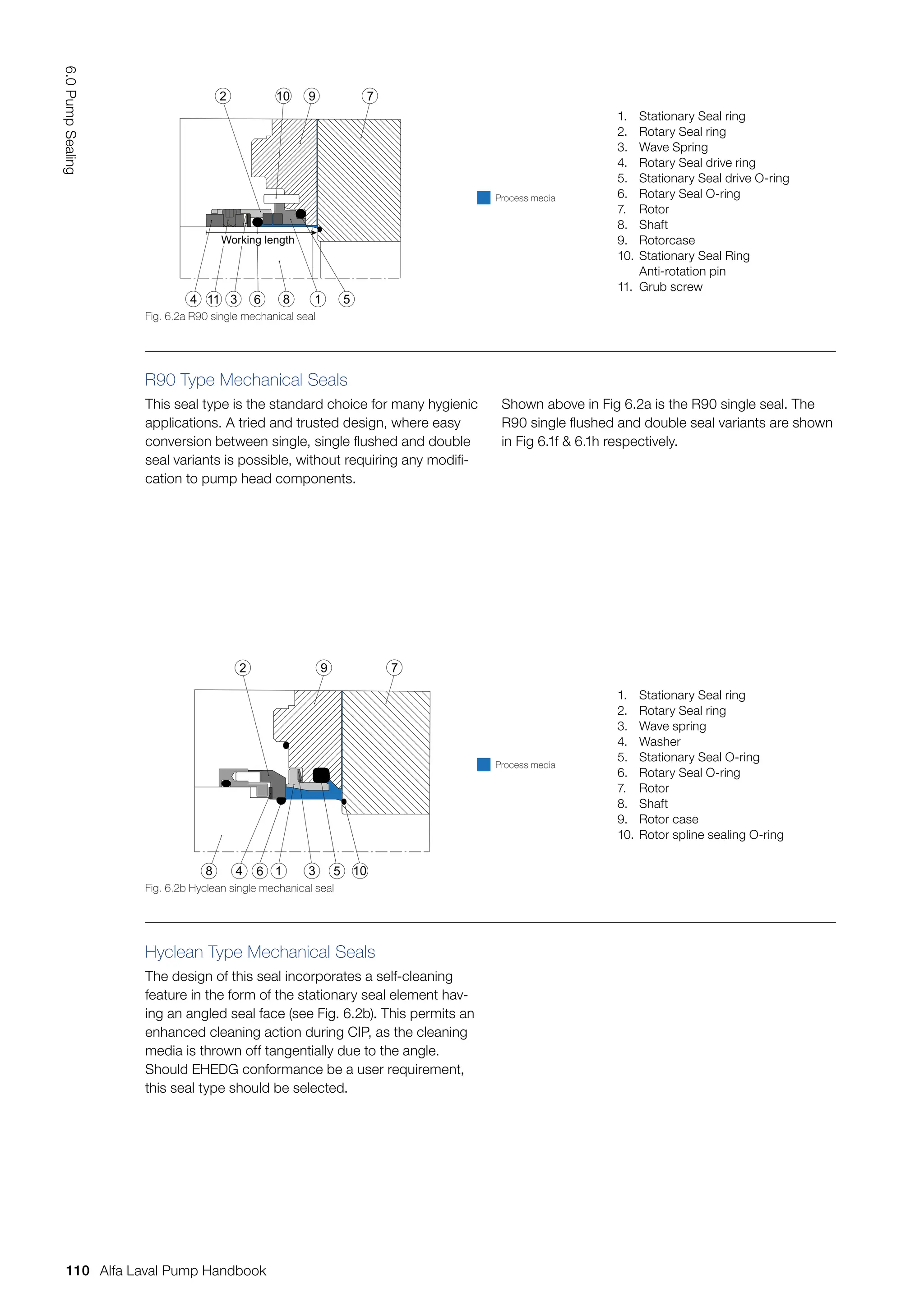
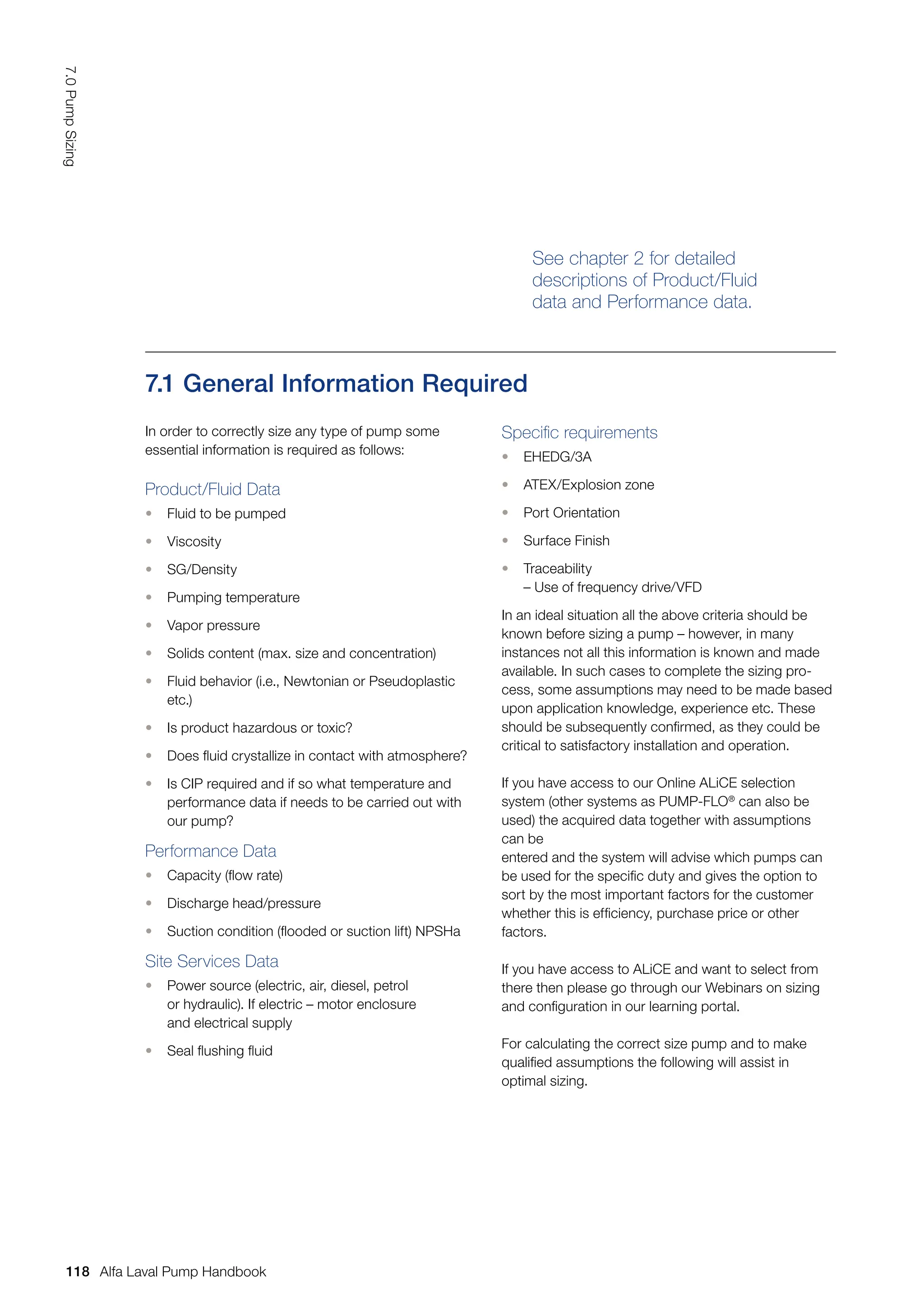
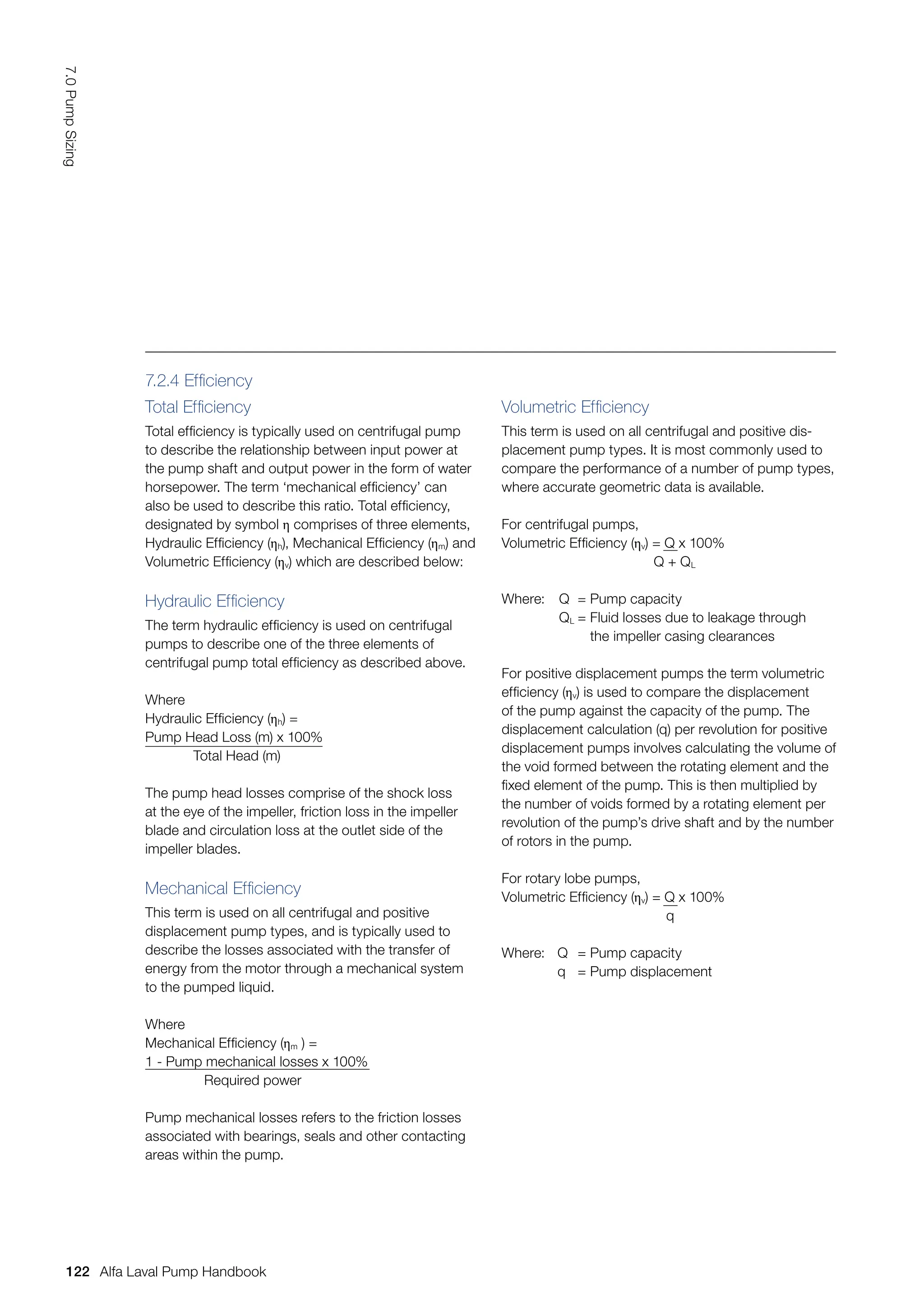
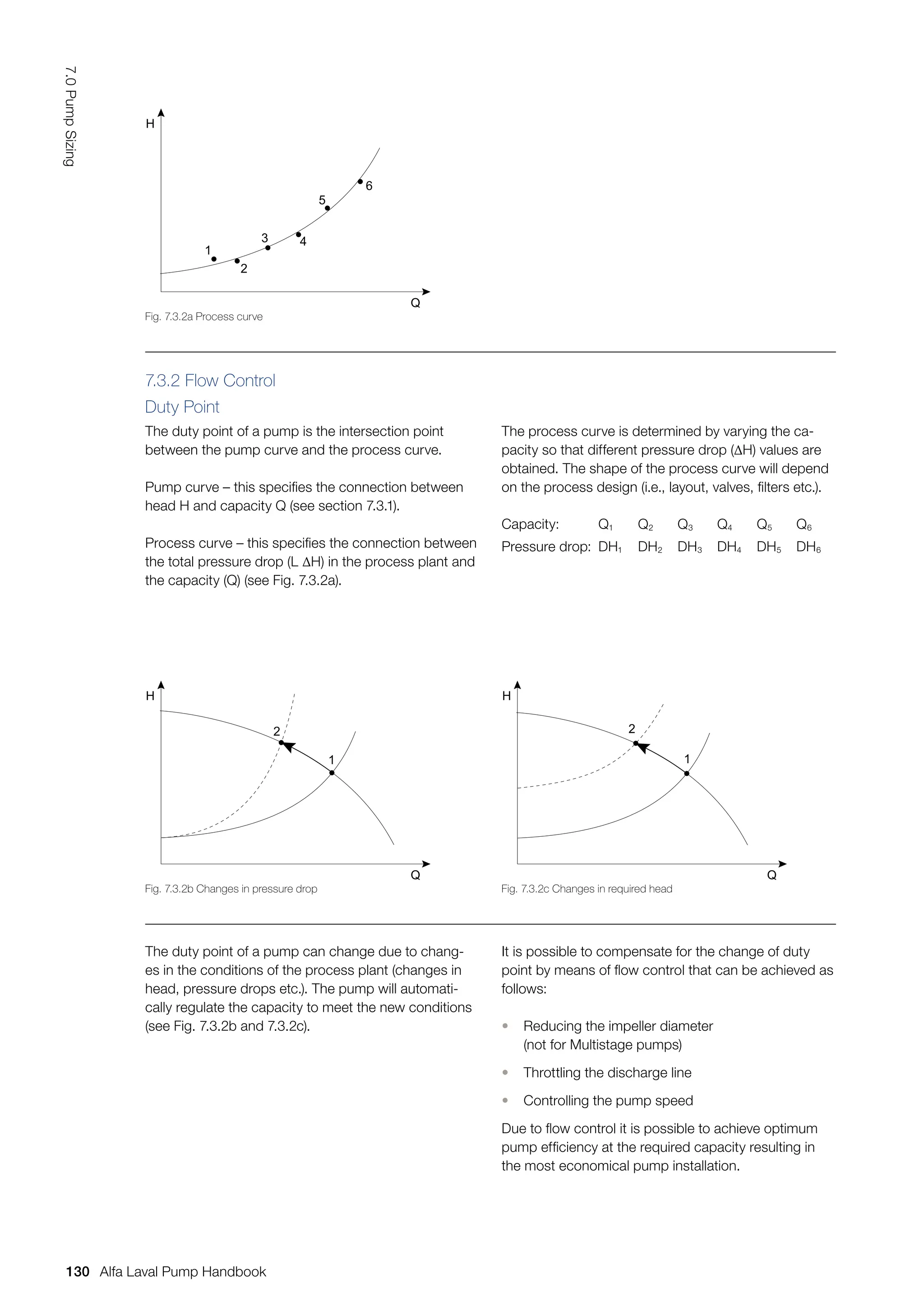
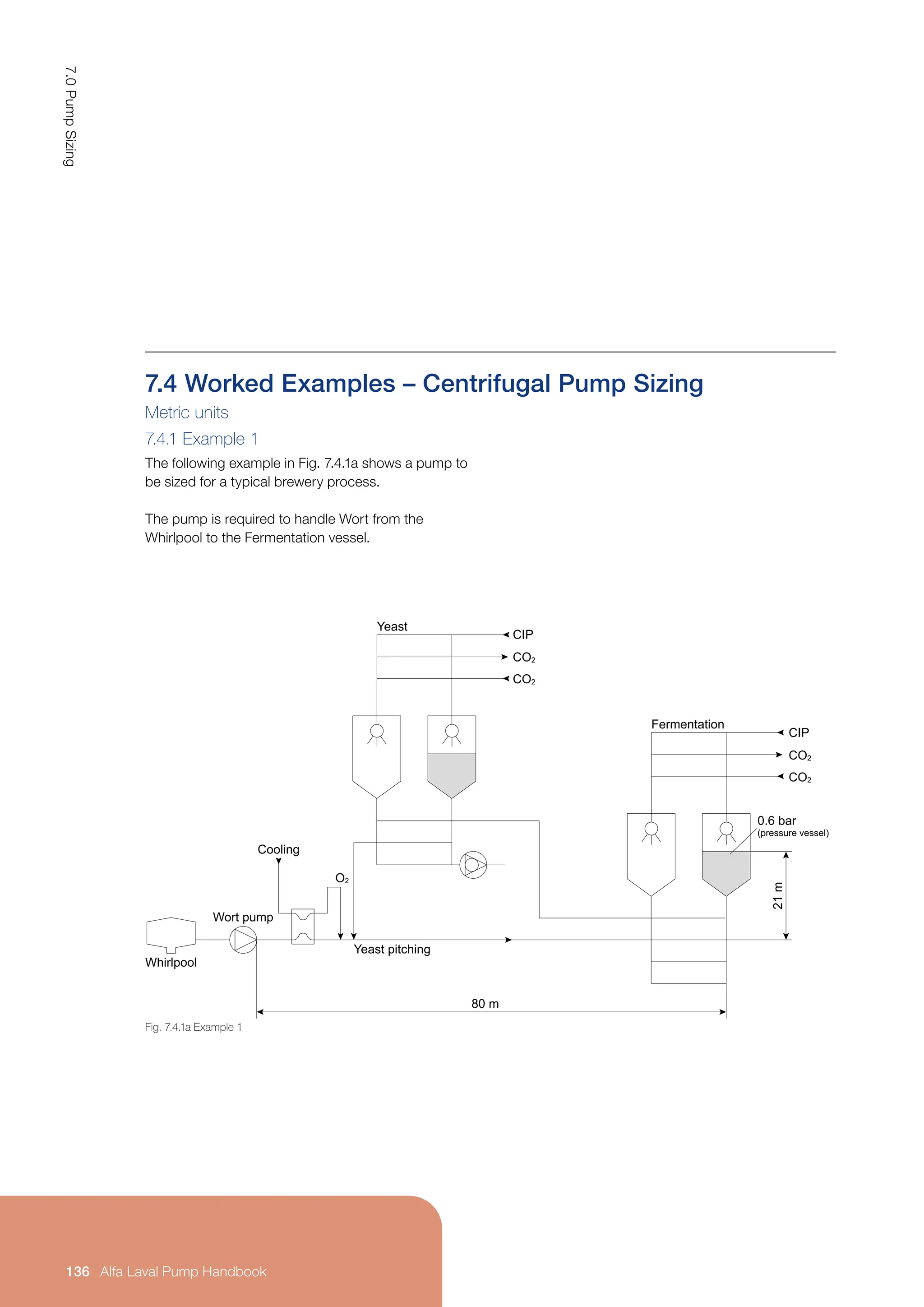
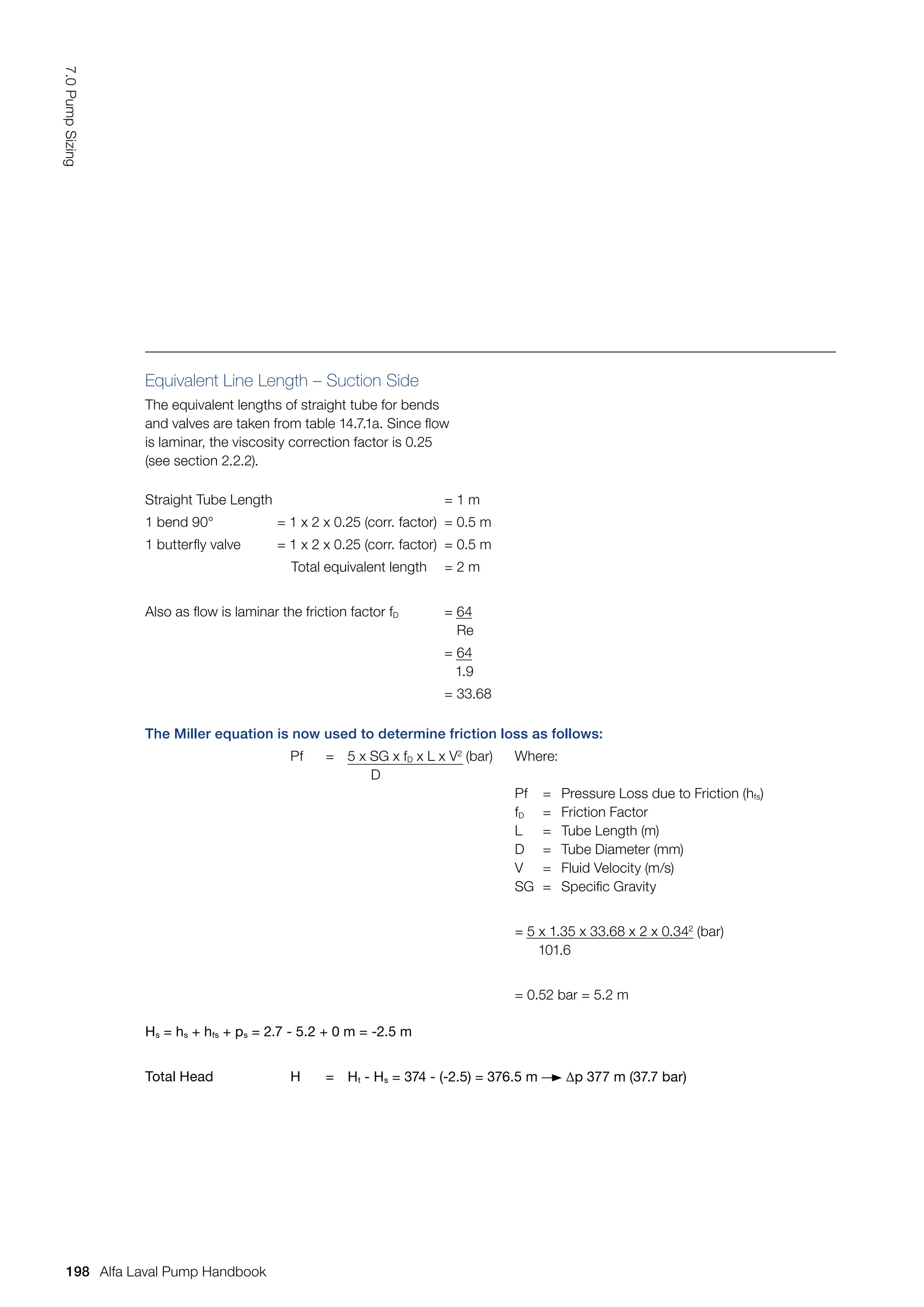
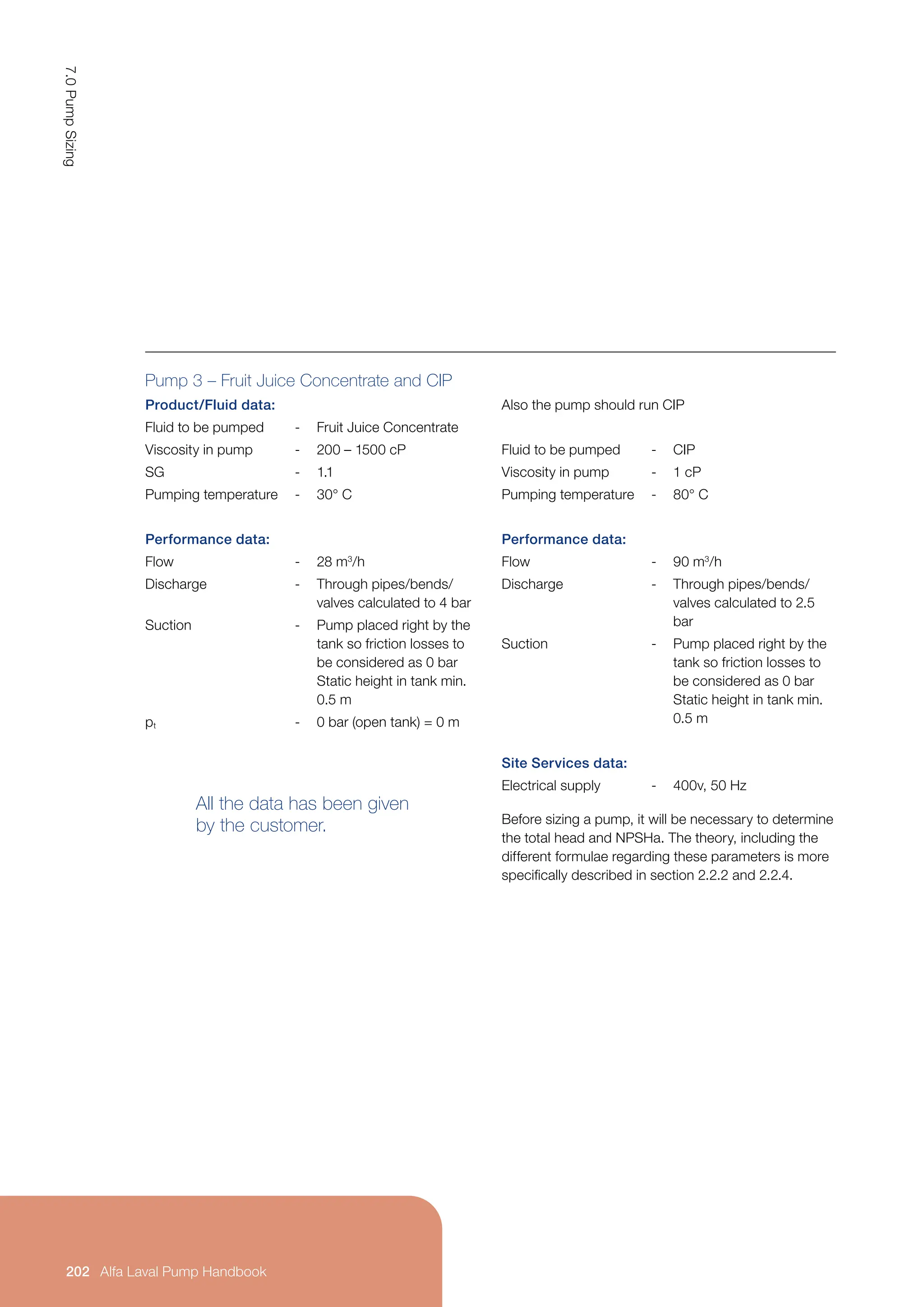
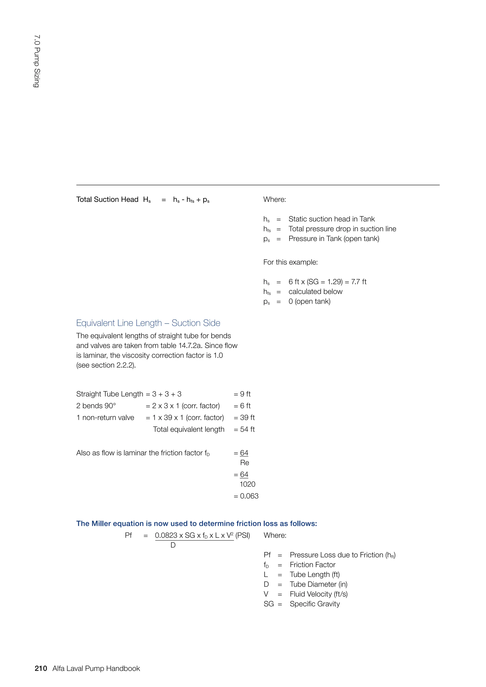
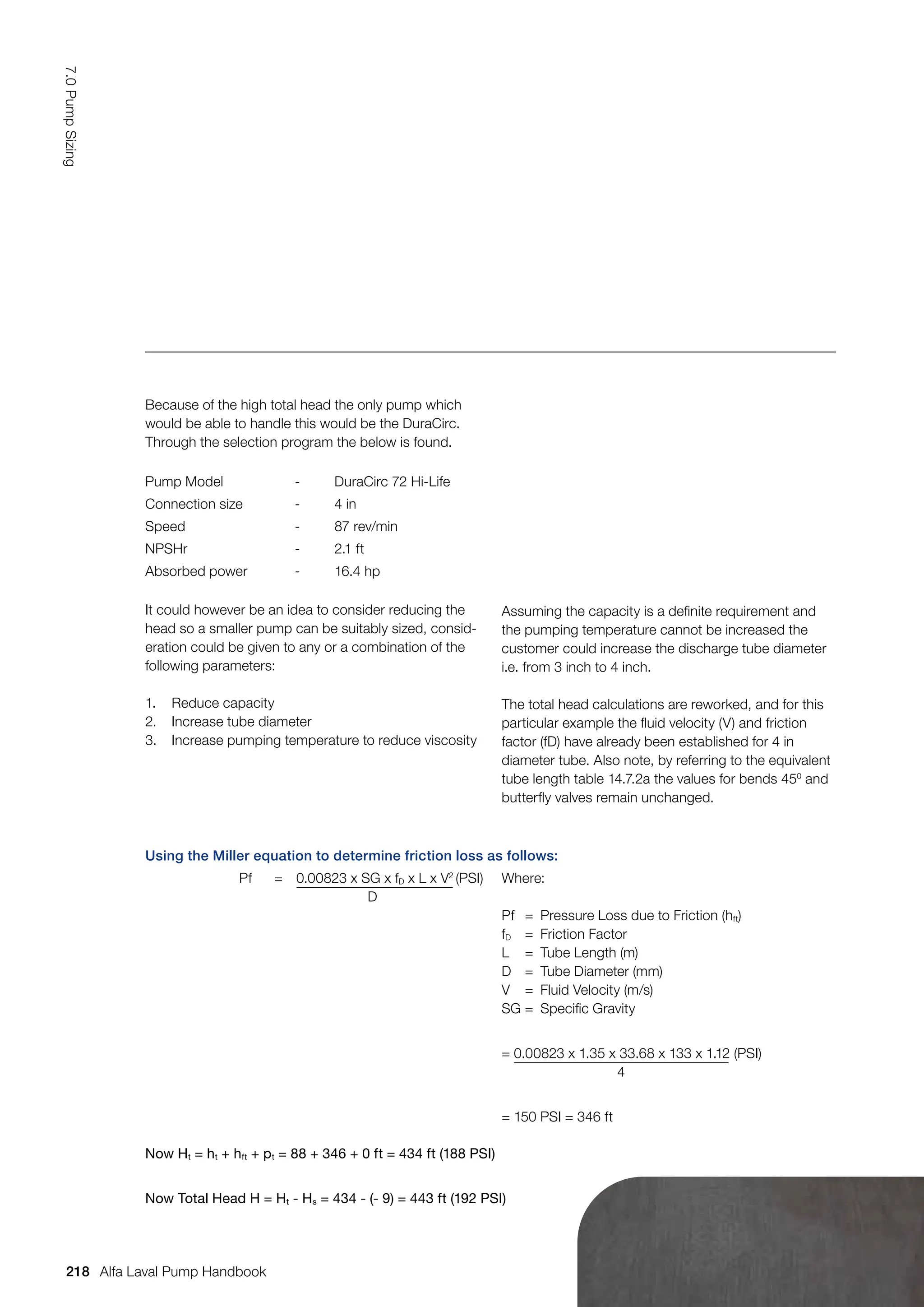
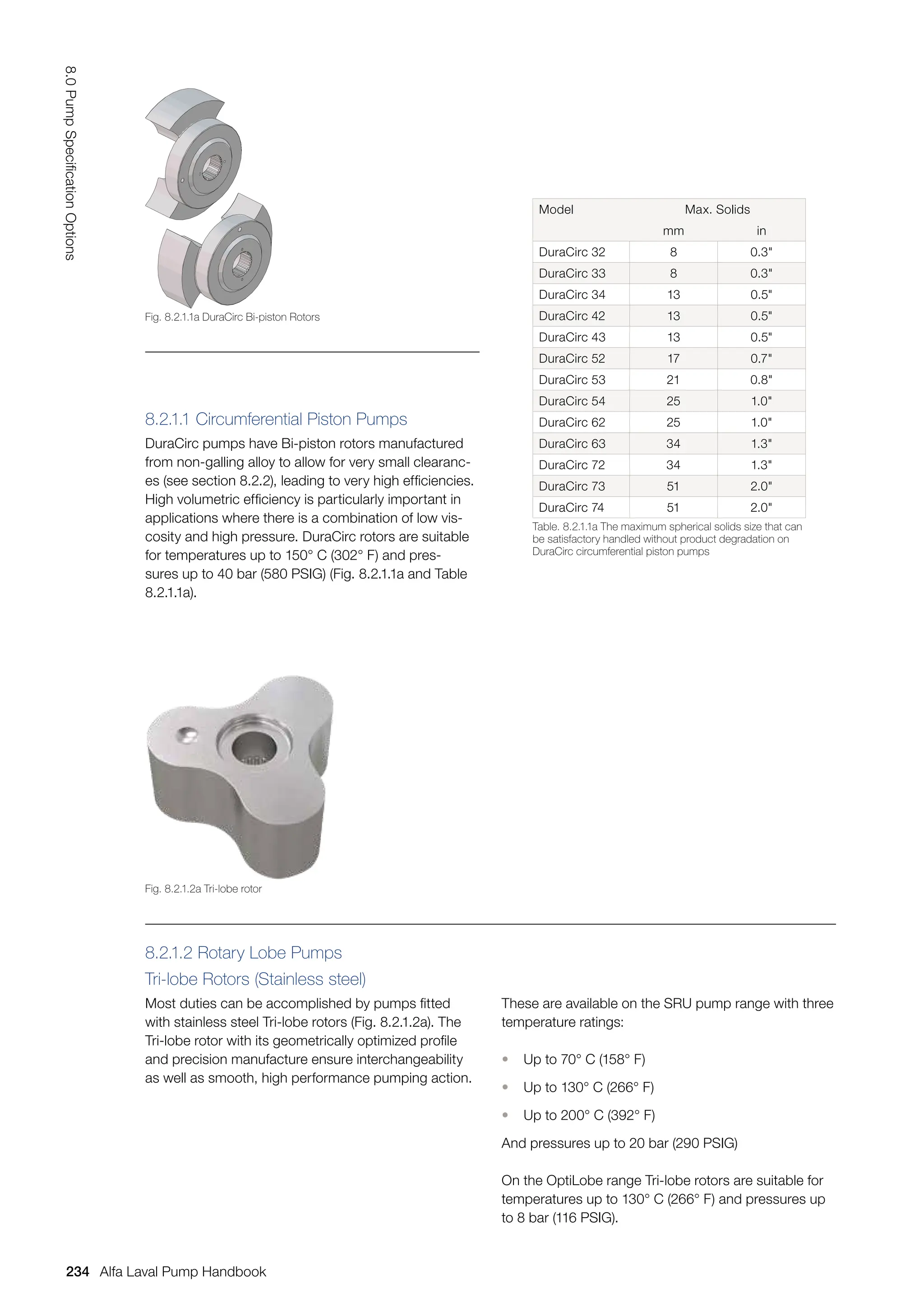
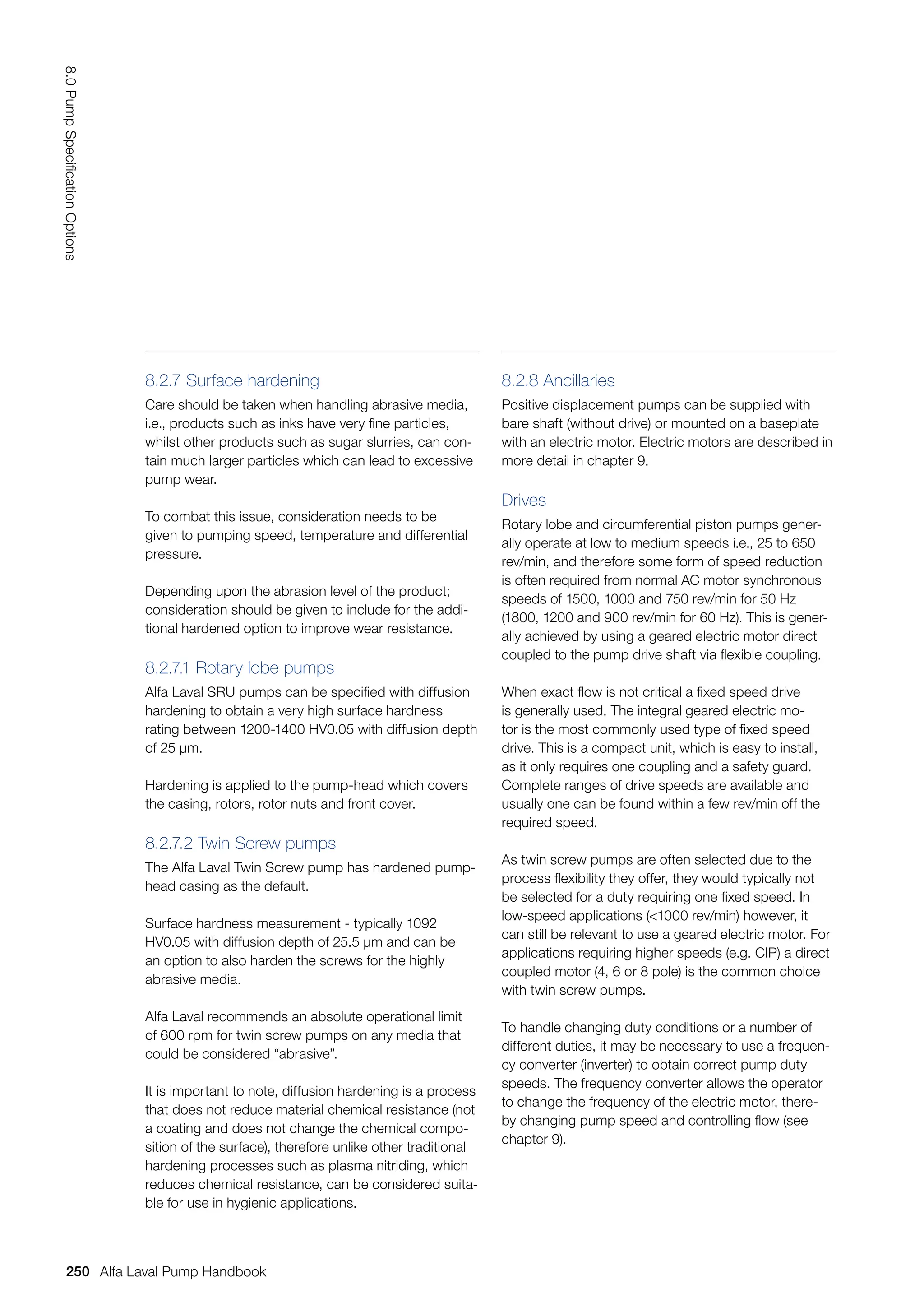
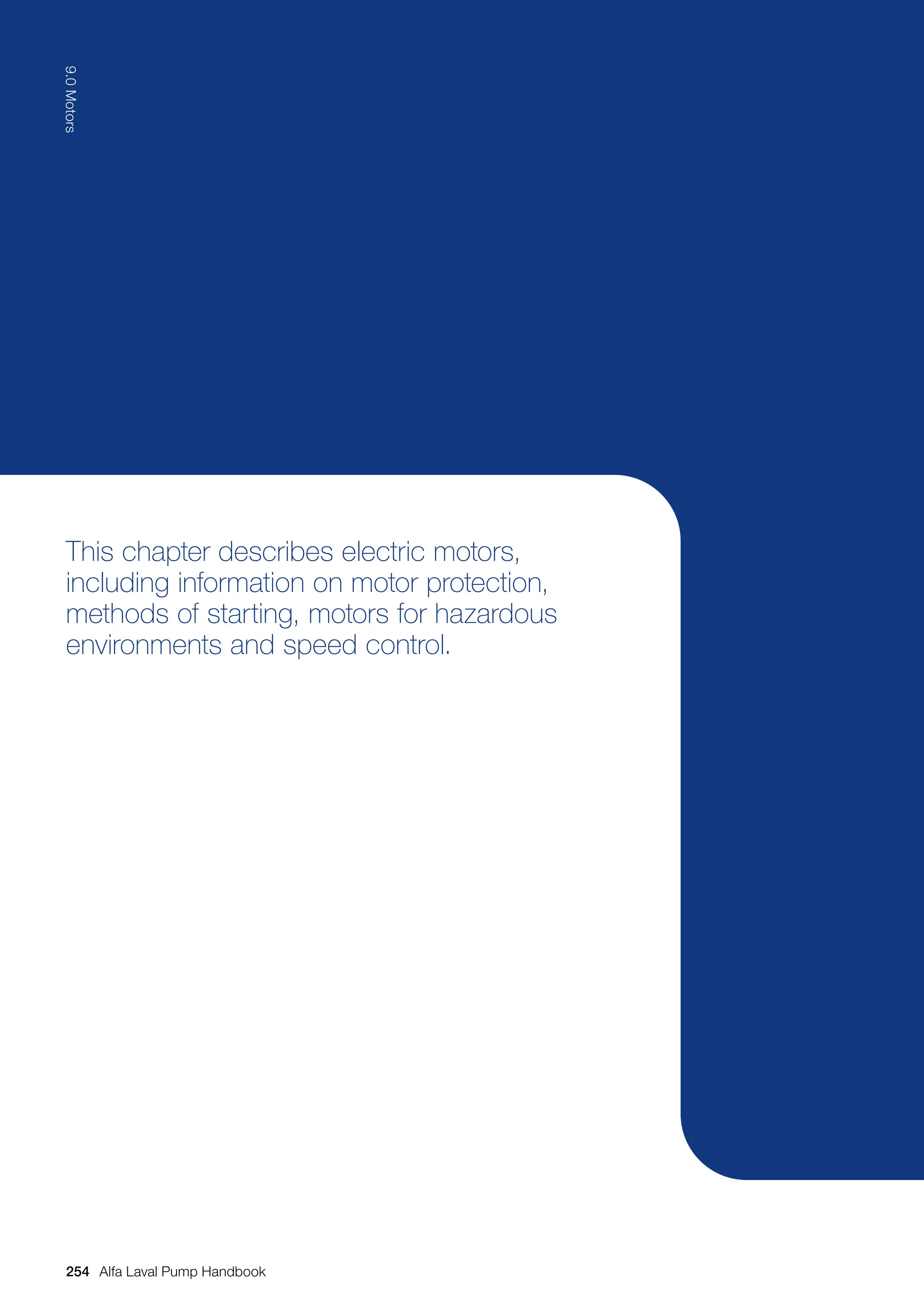
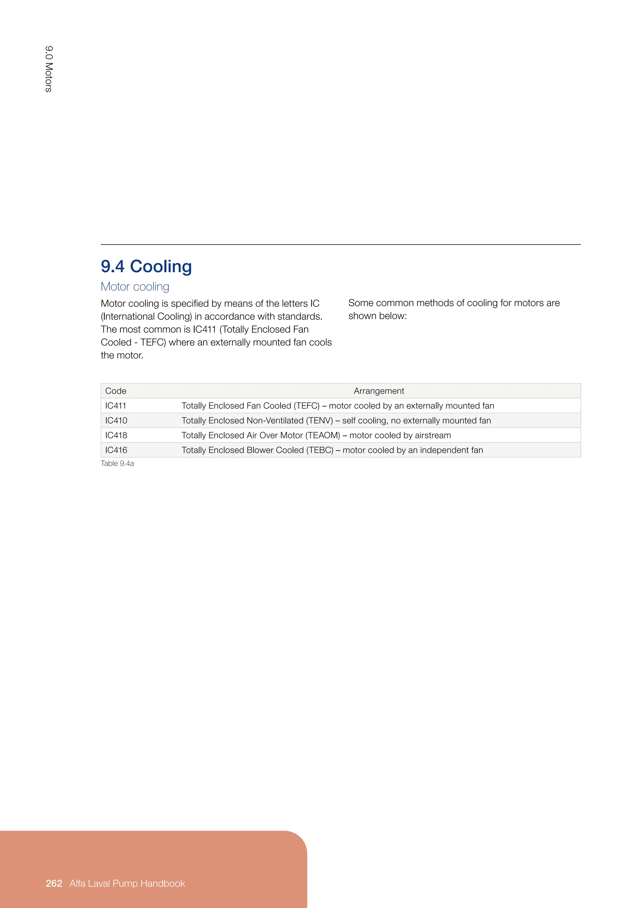
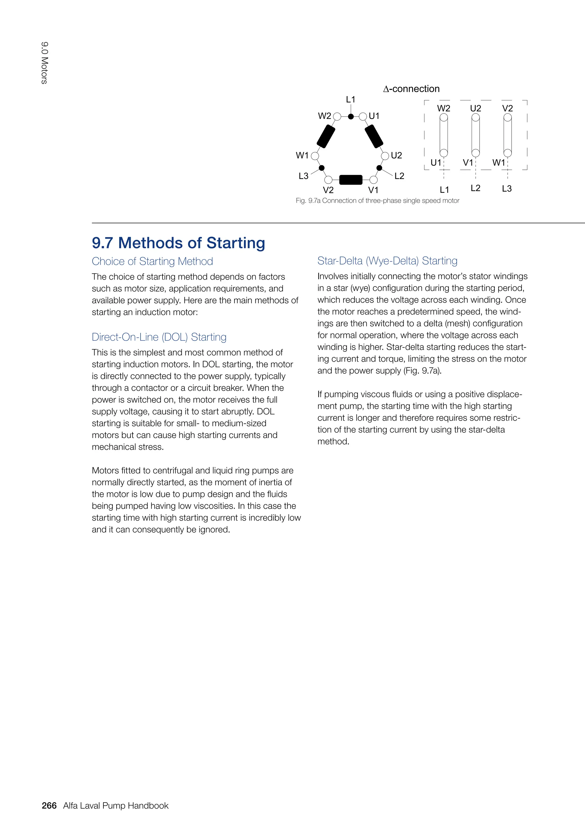
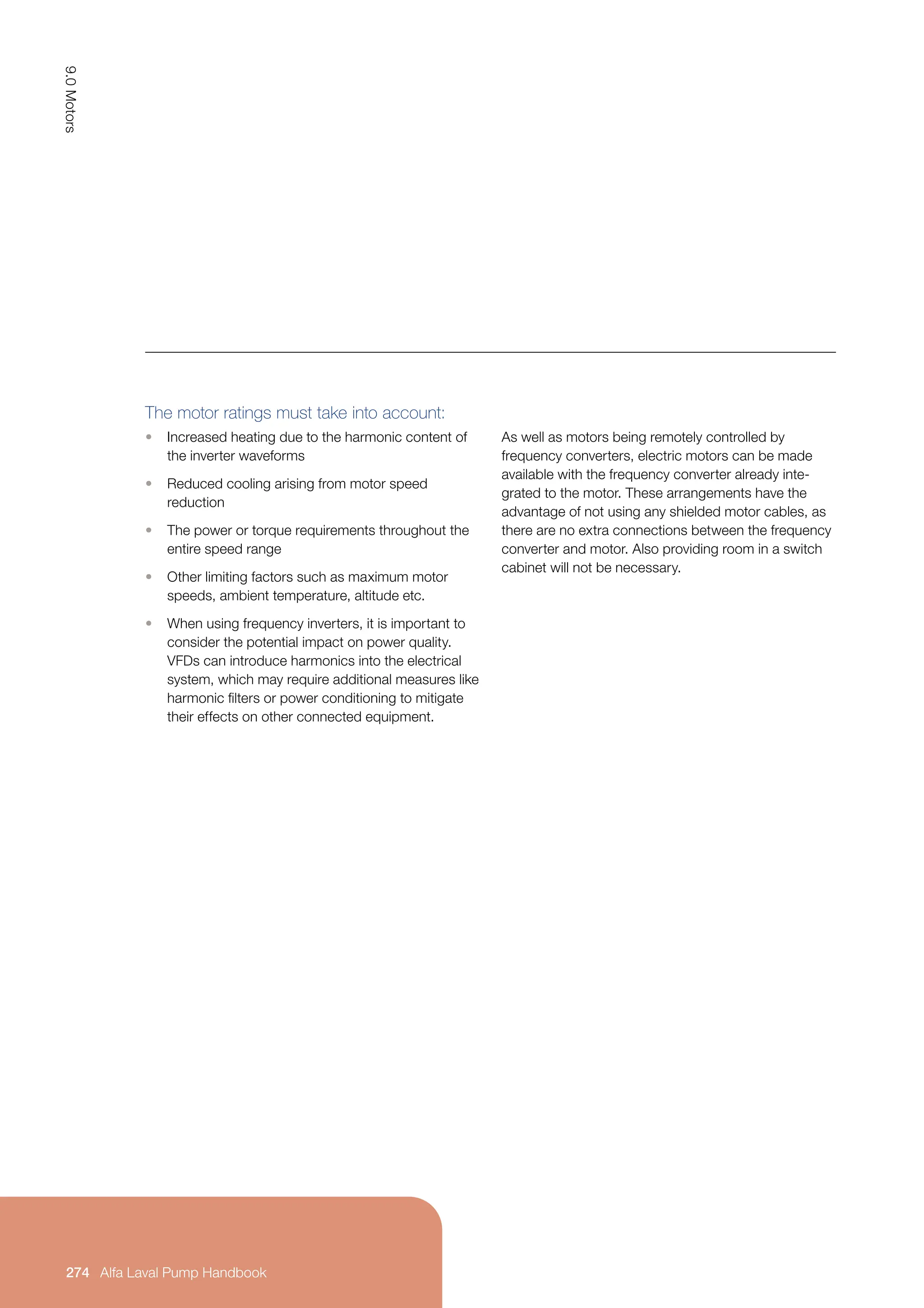
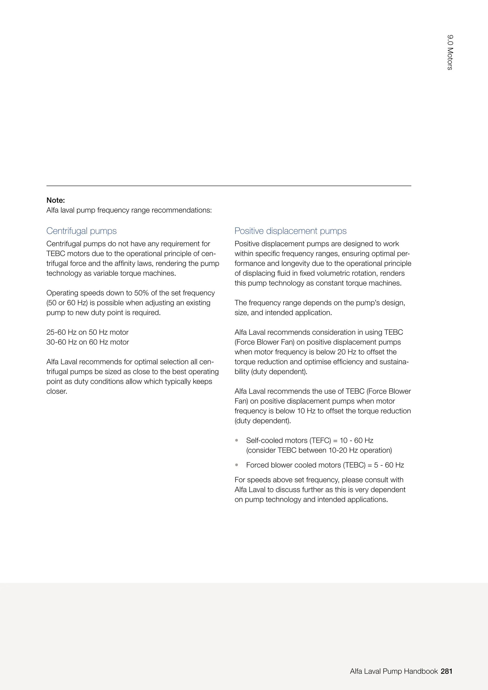
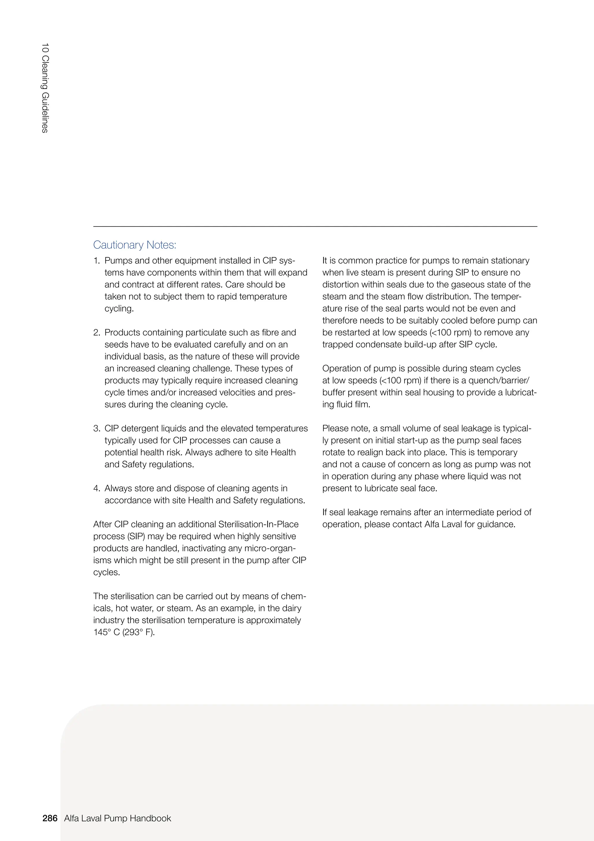
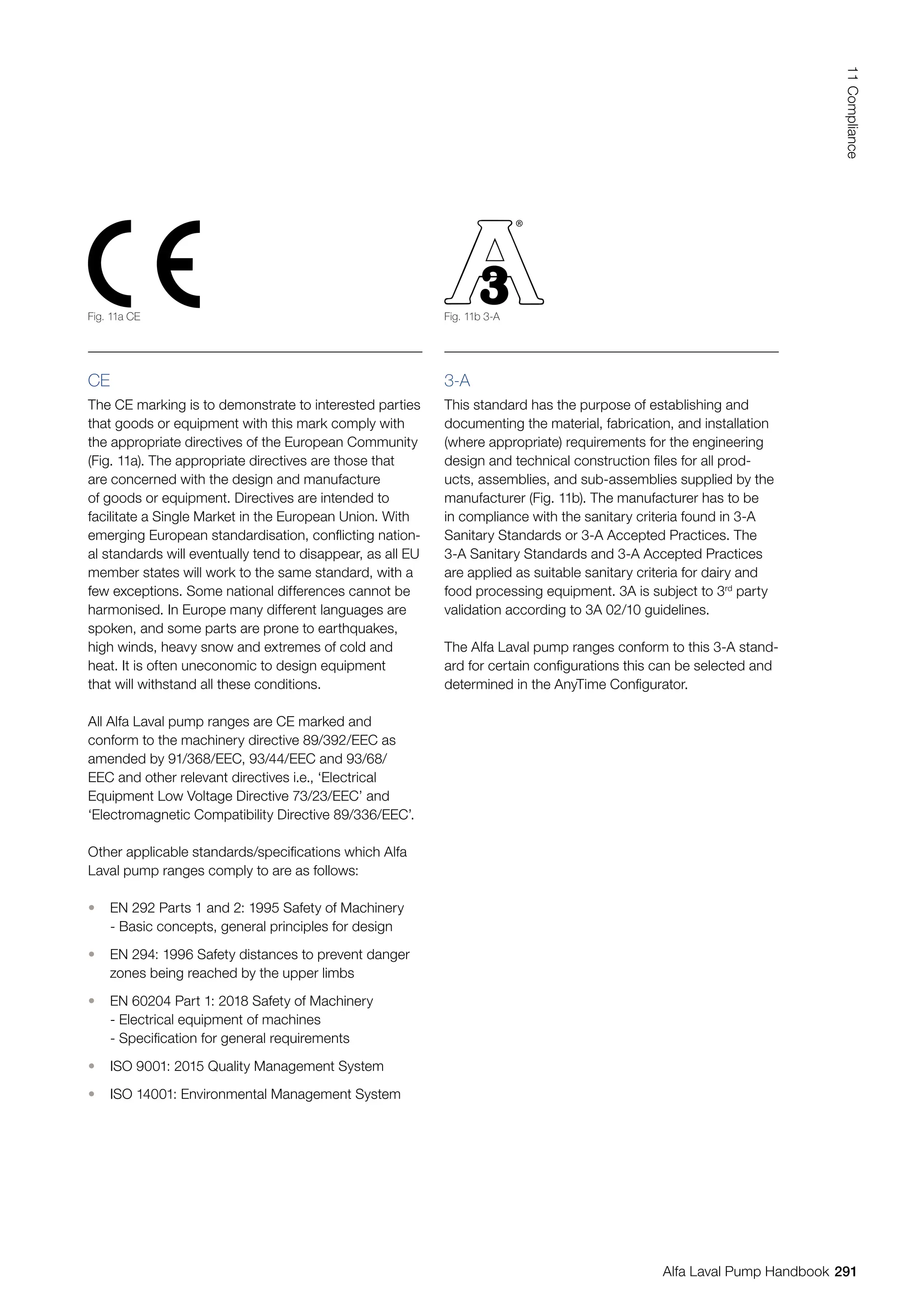
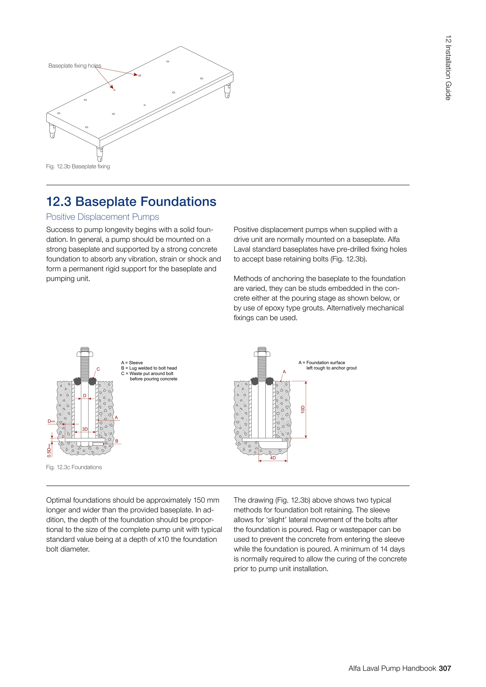
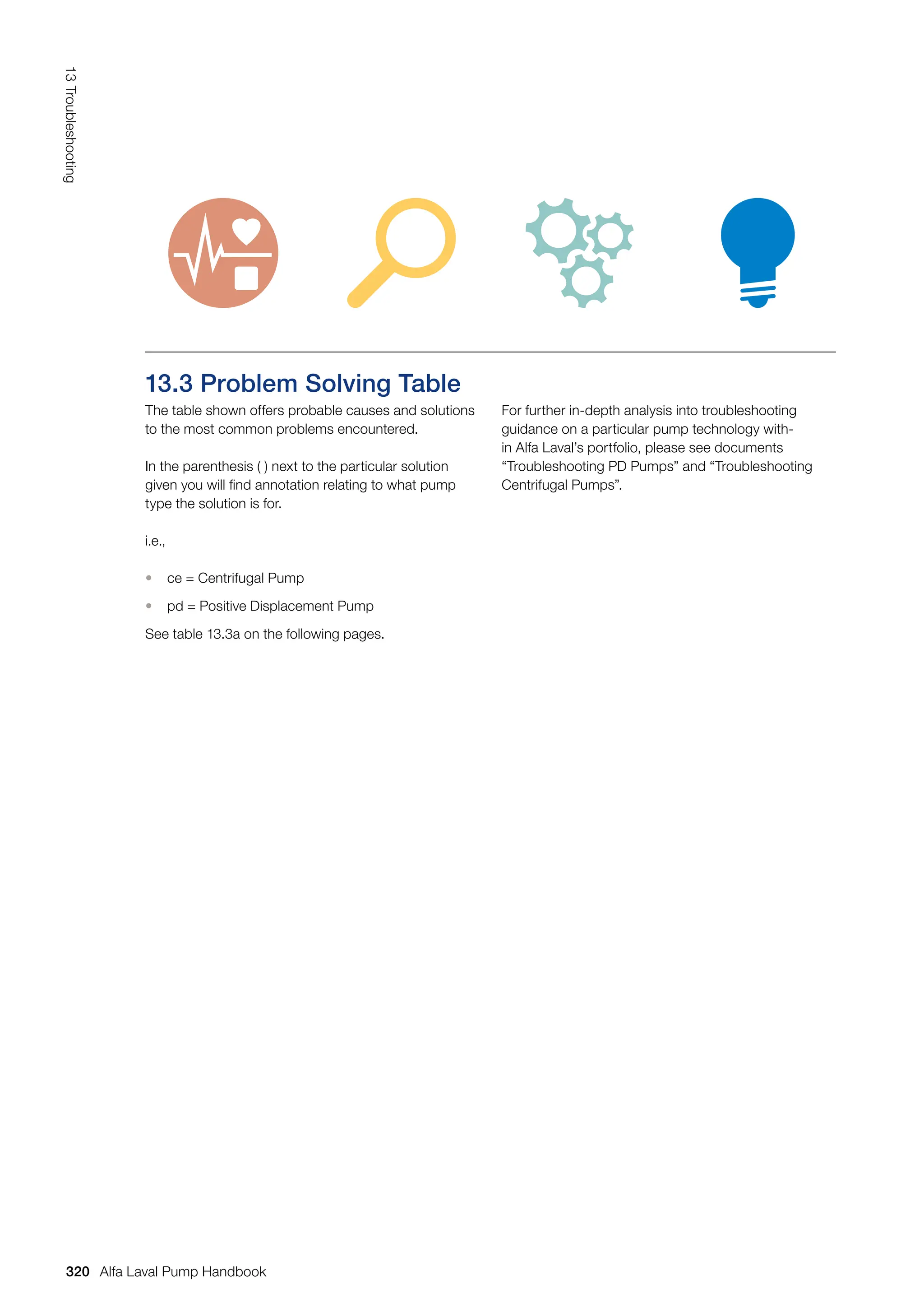
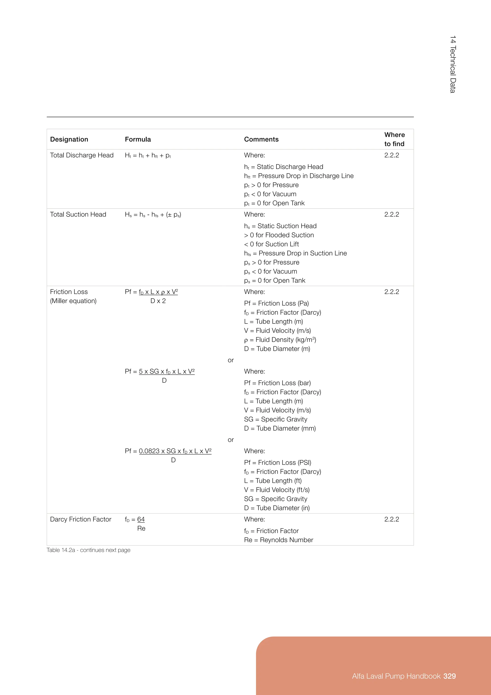
![This results in 100% torque decreasing to 5 Hz (See
Fig. 9.11.3c).
TEBC units can also be used to help optimise motor
selections where duty points are below the 2:1 motor
turn-down and require a larger motor to meet torque
requirements after derating.
To counter torque derating at reduced speeds, the
following two options can be considered:
1. Forced blower cooled motors (TEBC) are equipped
with a separate fan driven by a separate motor
thereby ensuring 100% airflow regardless of motor
running speed and no derating is required due to
increase motor temperature.
1.05
1.00
0.95
0.90
0.85
0.80
0.75
0.70
0.65
0.60
0.55
0.50
0.45
0.40
0 0.1
A = Constant Torque Range (No derating)
B = Here we can see full torque from 1.0 (50/60 Hz)
down to 0.1 with forced ventilation keeping
the motor cool
C = Forced ventilation. 50 Hz Supply
D = Note:
1.0 represents 100%
Frequency output: 50 or 60 Hz
E = 5-50 Hz
A
D
B
C
E
0.2 0.3 0.4 0.5 0.6 0.7 0.8 0.9 1.2 1.3 1.4 1.5 1.6 1.7 1.8 1.9
1.0
Torque derating for TEBC motors
[f/fn] - Operating frequency (p.u.)
[T/Tn]
-
Torque
derating
factor
(p.u.)
2.0
1.1 2.1
Fig. 9.11.3c Constant torque graph for TEBC motor
278
9.0
Motors
Alfa Laval Pump Handbook](https://image.slidesharecdn.com/pump-handbook-2024-251113133245-895f754e/75/Alfa-Laval-Pump-Handbook-Second-Edition-2023-280-2048.jpg)
![2. Increased motor size (see Fig. 9.11.3d). Increasing
motor size is the alternative solution. With this,
the motor is operated at a reduced load. Therefore,
there is less power loss and an additional increased
thermal reserve due to increased size of the motor.
Above the nominal frequency the available torque re-
duces, as the voltage is no longer increasing at higher
frequencies (see Fig. 9.11.3a) the magnetic flux reduc-
es. This range is known as the field weakening range.
A further increase in frequency in the field weakening
range therefore results in a torque reduction (See Fig.
9.11.3e).
1.05
1.00
0.95
0.90
0.85
0.80
0.75
0.70
0.65
0.60
0.55
0.50
0.45
0.40
0 0.1
A = Constant Torque
B = Torque derating
Here we can see full torque from
1.0 (50/60 Hz) down to 0.1 with forced
ventilation keeping the motor cool
C = Forced flux. Constant V/f. 50 Hz Supply
D = Note:
1.0 represents 100%
Frequency output: 50 or 60 Hz
0.5 would represent 50%; 25 or 30 Hz
E = 50 Hz
F = 50 Hz
A
D
B
C
E F
0.2 0.3 0.4 0.5 0.6 0.7 0.8 0.9 1.2 1.3 1.4 1.5 1.6 1.7 1.8 1.9
1.0
Torque derating for self cooling motors
[f/fn] - Operating frequency (p.u.)
[T
R
]
-
Torque
derating
factor
(p.u.)
2.0
1.1 2.1
Fig.9.11.3d Range of IEC motor frame sizes
Fig. 9.11.3e - Constant torque graph for TEFC motor
279
9.0
Motors
Alfa Laval Pump Handbook](https://image.slidesharecdn.com/pump-handbook-2024-251113133245-895f754e/75/Alfa-Laval-Pump-Handbook-Second-Edition-2023-281-2048.jpg)


![Speed/Capacity: Q1 = n1 ⇒ n2 = n1 x Q2
Q2 n2 Q1
[rev/min]
Speed/Head: H1 = n1
2
⇒ n2 = n1 x
H2 n2
2
[rev/min]
Speed/Power P1 = n1
3
⇒ n2 = n1 x
P2 n2
3
[rev/min]
√
3 P2
P1
√H2
H1
√c-b
a-b
Reducing Impeller Diameter
Reducing the impeller diameter can only be carried
out for centrifugal pumps. This will reduce the capacity
and the head.
Centrifugal Pump
The connection between Impeller Diameter (D),
Capacity (Q) and Head (H) is shown in Fig. 7.3.2d:
1. Before reducing
2. After reducing – the duty point moves towards point
2 when reducing the impeller diameter
If the impeller speed remains unchanged, the connec-
tion between Impeller Diameter (D), Capacity (Q), Head
(H) and Required Power (P) is shown by the following
formulas: The formula is for guidance purpos-
es only. It is recommended to add a
safety factor of 10–15% to the new
diameter.
Most pump flow curves show characteristics for
different impeller diameters to enable the correct
impeller diameter to be selected.
Reducing the impeller diameter by up to 20% will not
affect the efficiency of the pump much. If the reduction
in impeller diameter exceeds 20%, the pump efficiency
will decrease.
The impeller diameter is reduced to D2 by means of
the following formula:
D2 = D1 x [mm]
Where:
D1 = Standard Diameter before Reducing
a = Maximum Duty Point
b = Minimum Duty Point
c = Required Duty Point
Fig. 7.3.2d Reducing impeller diameter
H
2
1
D1
D2
Q1
Q2
H2
H1
Q
131
7.0
Pump
Sizing
Alfa Laval Pump Handbook](https://crownmelresort.com/image.slidesharecdn.com/pump-handbook-2024-251113133245-895f754e/75/Alfa-Laval-Pump-Handbook-Second-Edition-2023-133-2048.jpg)

![The most common form of
speed control is by means
of a frequency converter
(see section 9.10).
Speed/Capacity: Q1 = n1 ⇒ n2 = n1 x Q2
Q2 n2 Q1
[rev/min]
Speed/Head: H1 = n1
2
⇒ n2 = n1 x
H2 n2
2
[rev/min]
Speed/Power P1 = n1
3
⇒ n2 = n1 x
P2 n2
3
[rev/min]
√
3 P2
P1
√H2
H1
If the impeller dimensions remain unchanged, the
connection between Impeller Speed (n), Capacity (Q),
Head (H) and Required Power (P) is shown by the
following formulas:
As shown from the above formulas the impeller speed
affects capacity, head and required power as follows:
• Half speed results in capacity x 0.5
• Half speed results in head x 0.25
• Half speed results in required power x 0.125
Speed control will not affect the efficiency much
providing changes do not exceed 20%.
7.3.3 Alternative Pump Installations
Pumps Coupled in Series
It is possible to increase the head in a pump installa-
tion by two or more pumps being coupled in series
(see Fig. 7.3.3a).
The Capacity (Q) will always be constant throughout
the pump series (see Fig. 7.3.3b).
The head can vary depending on the pump sizes.
The outlet of pump 1 is connected to the inlet of
pump 2.
Pump 2 must be able to withstand the outlet head
from pump 1.
Fig. 7.3.3a Principle of connection
2
H = H1 + H2 Q = Constant
1
H2
H1
133
7.0
Pump
Sizing
Alfa Laval Pump Handbook](https://crownmelresort.com/image.slidesharecdn.com/pump-handbook-2024-251113133245-895f754e/75/Alfa-Laval-Pump-Handbook-Second-Edition-2023-135-2048.jpg)


![With a self-cooled (TEFC) motor on a supply frequency
of 50 Hz, there is a constant torque between 50 - 25
Hz (50% or 2:1) meaning no derating in torque output.
Below 25 Hz, the torque output is derated due to the
slower running speed of the integrated fan, in order
to dissipate the additional heat generated (see Fig.
9.11.3b).
1.05
1.00
0.95
0.90
0.85
0.80
0.75
0.70
0.65
0.60
0.55
0.50
0.45
0.40
0 0.1
A = Slower the speed, the greater the torque derates
B = Constant Torque Range (No derating)
C = Constant flux. Constant V/f. 50 Hz Supply
D = Note:
1.0 represents 100%
Frequency output: 50 or 60 Hz
0.5 would represent 50%; 25 or 30 Hz
E = 25 Hz
F = 50 Hz
A
D
B
C
E F
0.2 0.3 0.4 0.5 0.6 0.7 0.8 0.9 1.2 1.3 1.4 1.5 1.6 1.7 1.8 1.9
1.0
Torque derating for self cooling motors
[f/fn] - Operating frequency (p.u.)
[T
R
]
—
Torque
derating
factor
(p.u.)
2.0
1.1 2.1
Fig. 9.11.3b Above shows the relationship of torque to frequency
277
9.0
Motors
Alfa Laval Pump Handbook
Alfa Laval Pump Handbook](https://crownmelresort.com/image.slidesharecdn.com/pump-handbook-2024-251113133245-895f754e/75/Alfa-Laval-Pump-Handbook-Second-Edition-2023-279-2048.jpg)
![This results in 100% torque decreasing to 5 Hz (See
Fig. 9.11.3c).
TEBC units can also be used to help optimise motor
selections where duty points are below the 2:1 motor
turn-down and require a larger motor to meet torque
requirements after derating.
To counter torque derating at reduced speeds, the
following two options can be considered:
1. Forced blower cooled motors (TEBC) are equipped
with a separate fan driven by a separate motor
thereby ensuring 100% airflow regardless of motor
running speed and no derating is required due to
increase motor temperature.
1.05
1.00
0.95
0.90
0.85
0.80
0.75
0.70
0.65
0.60
0.55
0.50
0.45
0.40
0 0.1
A = Constant Torque Range (No derating)
B = Here we can see full torque from 1.0 (50/60 Hz)
down to 0.1 with forced ventilation keeping
the motor cool
C = Forced ventilation. 50 Hz Supply
D = Note:
1.0 represents 100%
Frequency output: 50 or 60 Hz
E = 5-50 Hz
A
D
B
C
E
0.2 0.3 0.4 0.5 0.6 0.7 0.8 0.9 1.2 1.3 1.4 1.5 1.6 1.7 1.8 1.9
1.0
Torque derating for TEBC motors
[f/fn] - Operating frequency (p.u.)
[T/Tn]
-
Torque
derating
factor
(p.u.)
2.0
1.1 2.1
Fig. 9.11.3c Constant torque graph for TEBC motor
278
9.0
Motors
Alfa Laval Pump Handbook](https://crownmelresort.com/image.slidesharecdn.com/pump-handbook-2024-251113133245-895f754e/75/Alfa-Laval-Pump-Handbook-Second-Edition-2023-280-2048.jpg)
![2. Increased motor size (see Fig. 9.11.3d). Increasing
motor size is the alternative solution. With this,
the motor is operated at a reduced load. Therefore,
there is less power loss and an additional increased
thermal reserve due to increased size of the motor.
Above the nominal frequency the available torque re-
duces, as the voltage is no longer increasing at higher
frequencies (see Fig. 9.11.3a) the magnetic flux reduc-
es. This range is known as the field weakening range.
A further increase in frequency in the field weakening
range therefore results in a torque reduction (See Fig.
9.11.3e).
1.05
1.00
0.95
0.90
0.85
0.80
0.75
0.70
0.65
0.60
0.55
0.50
0.45
0.40
0 0.1
A = Constant Torque
B = Torque derating
Here we can see full torque from
1.0 (50/60 Hz) down to 0.1 with forced
ventilation keeping the motor cool
C = Forced flux. Constant V/f. 50 Hz Supply
D = Note:
1.0 represents 100%
Frequency output: 50 or 60 Hz
0.5 would represent 50%; 25 or 30 Hz
E = 50 Hz
F = 50 Hz
A
D
B
C
E F
0.2 0.3 0.4 0.5 0.6 0.7 0.8 0.9 1.2 1.3 1.4 1.5 1.6 1.7 1.8 1.9
1.0
Torque derating for self cooling motors
[f/fn] - Operating frequency (p.u.)
[T
R
]
-
Torque
derating
factor
(p.u.)
2.0
1.1 2.1
Fig.9.11.3d Range of IEC motor frame sizes
Fig. 9.11.3e - Constant torque graph for TEFC motor
279
9.0
Motors
Alfa Laval Pump Handbook](https://crownmelresort.com/image.slidesharecdn.com/pump-handbook-2024-251113133245-895f754e/75/Alfa-Laval-Pump-Handbook-Second-Edition-2023-281-2048.jpg)


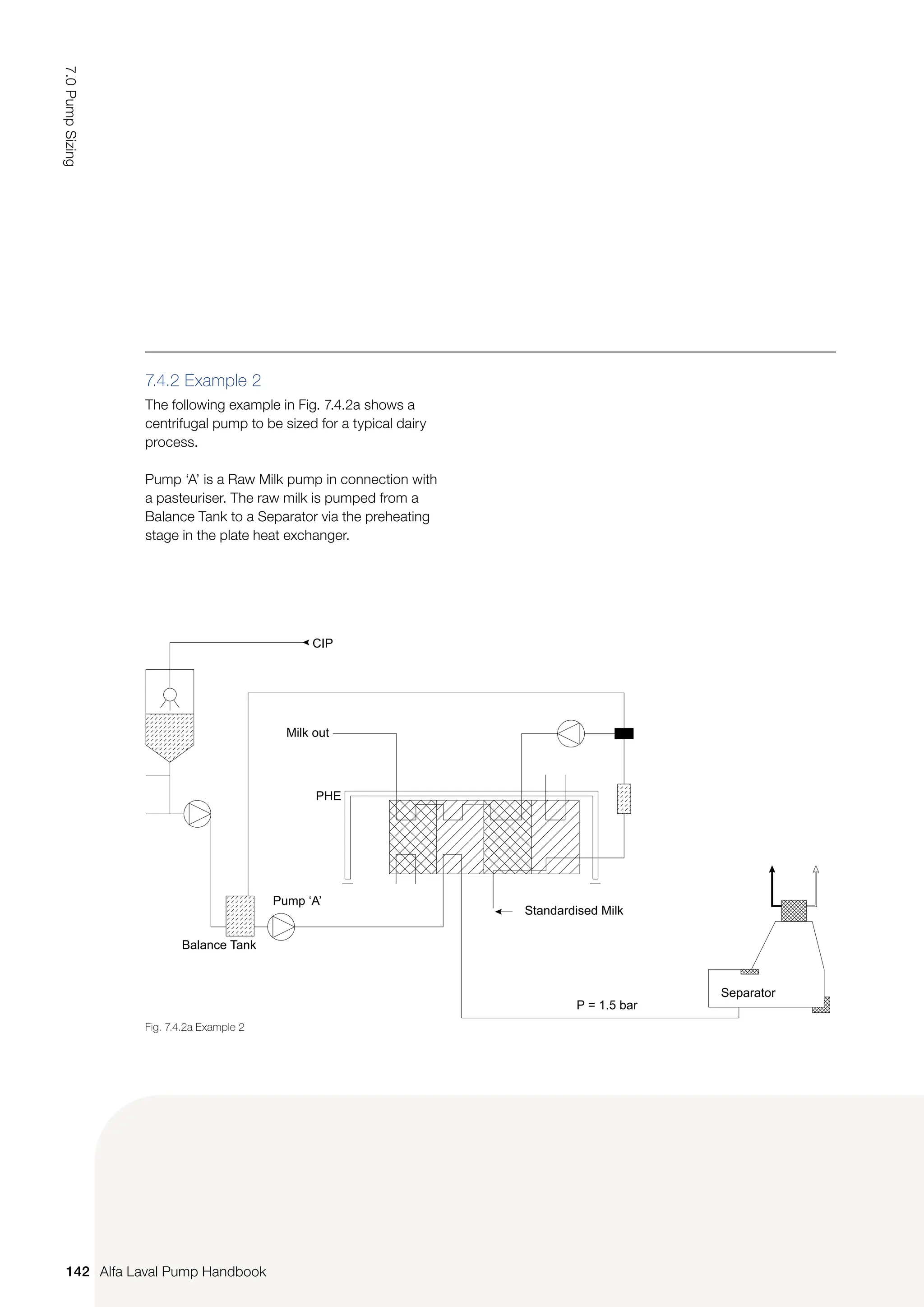
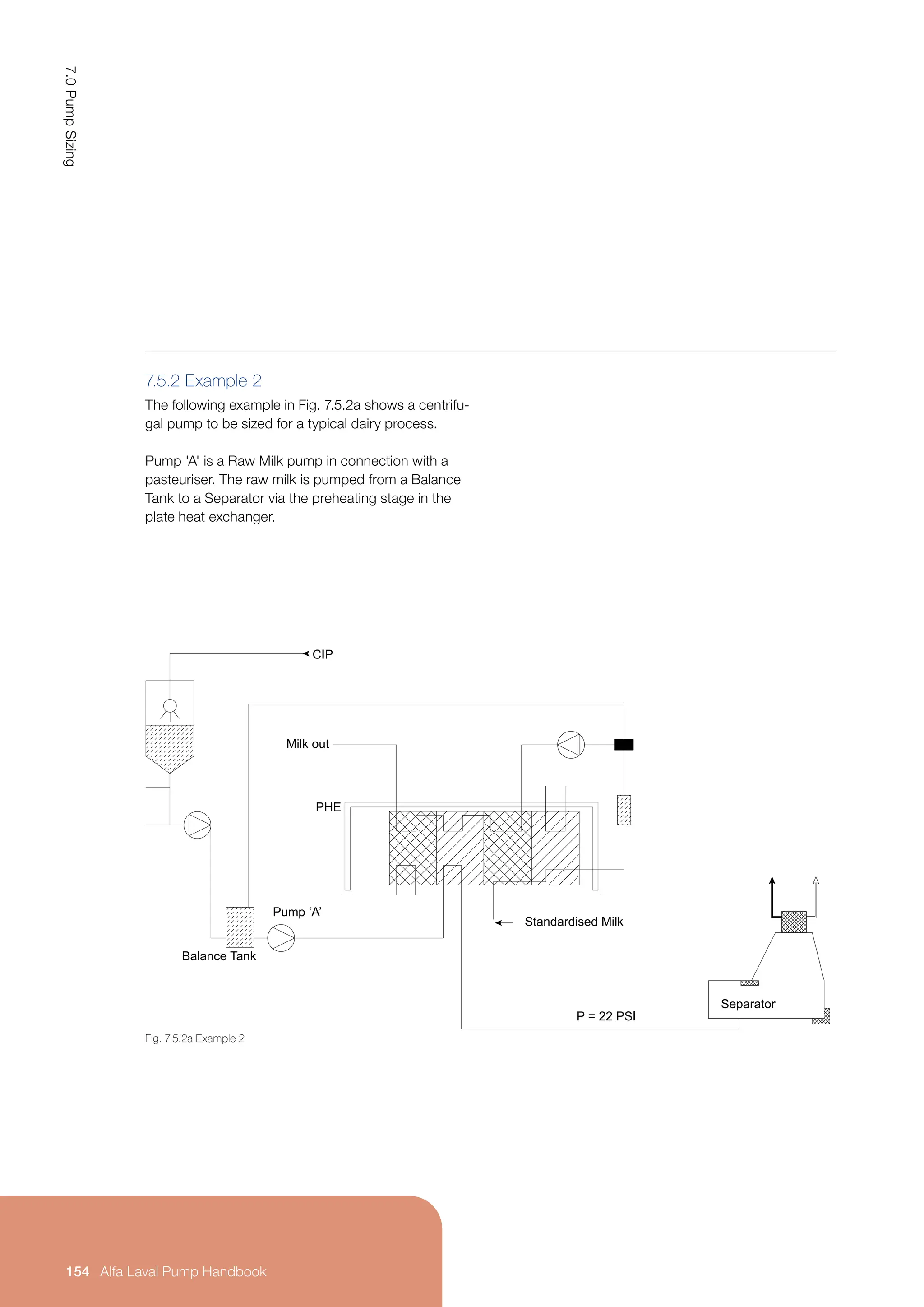
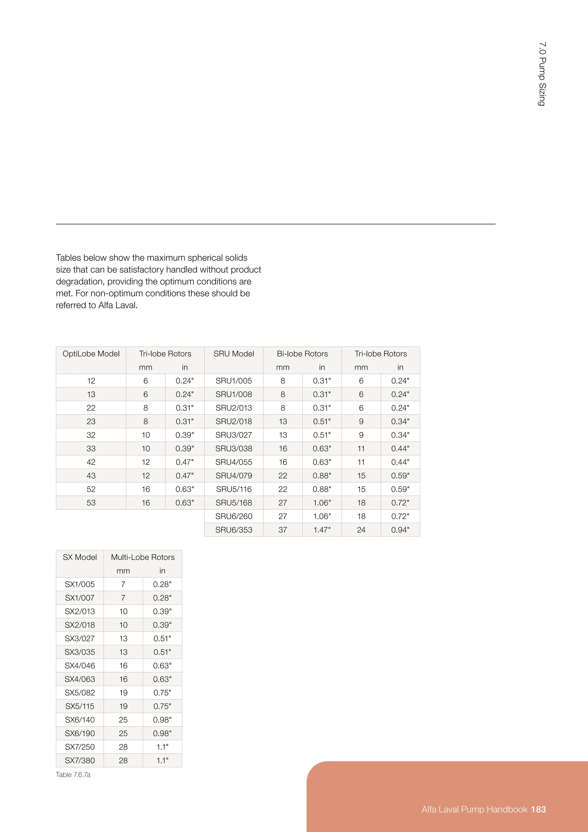
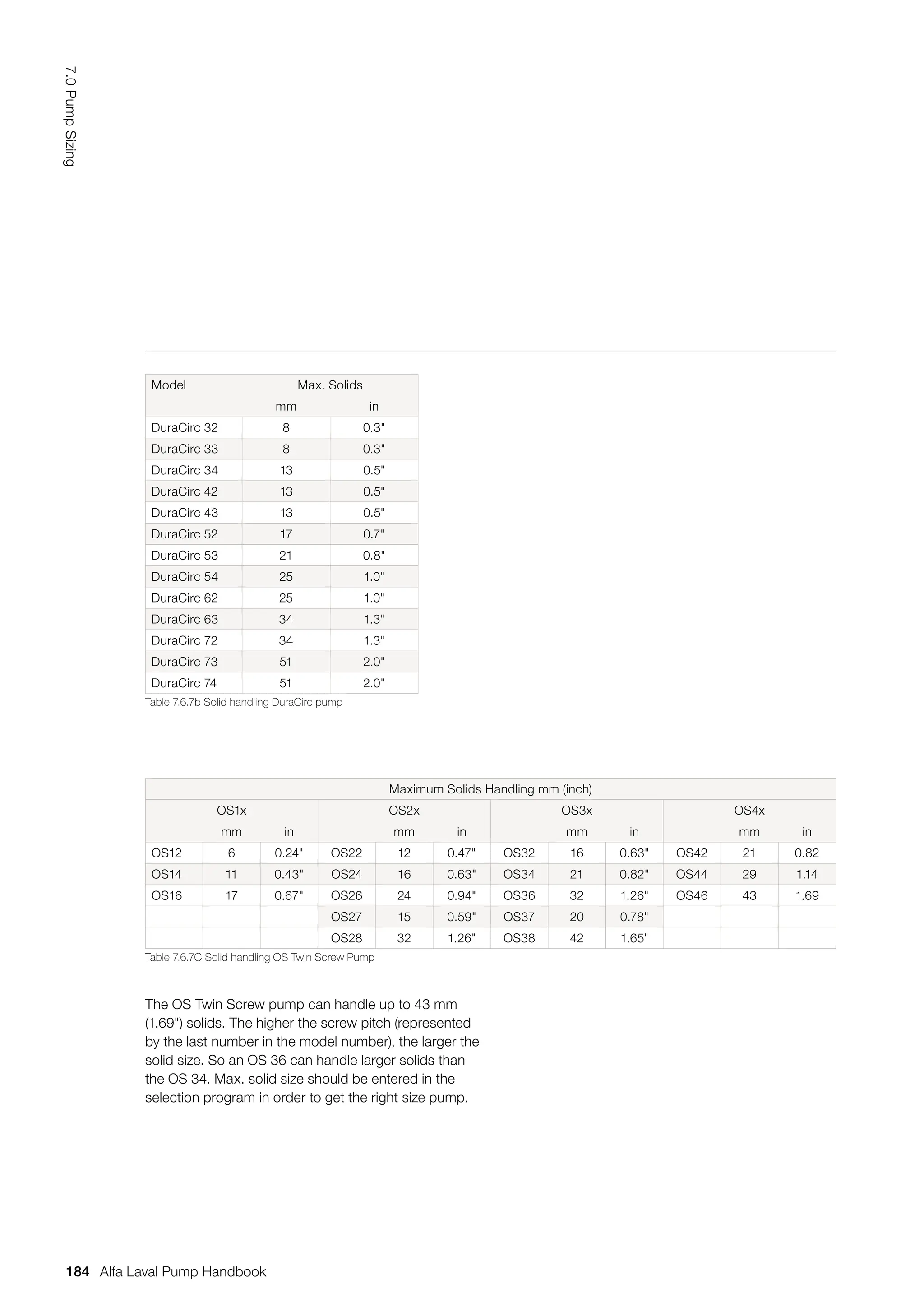
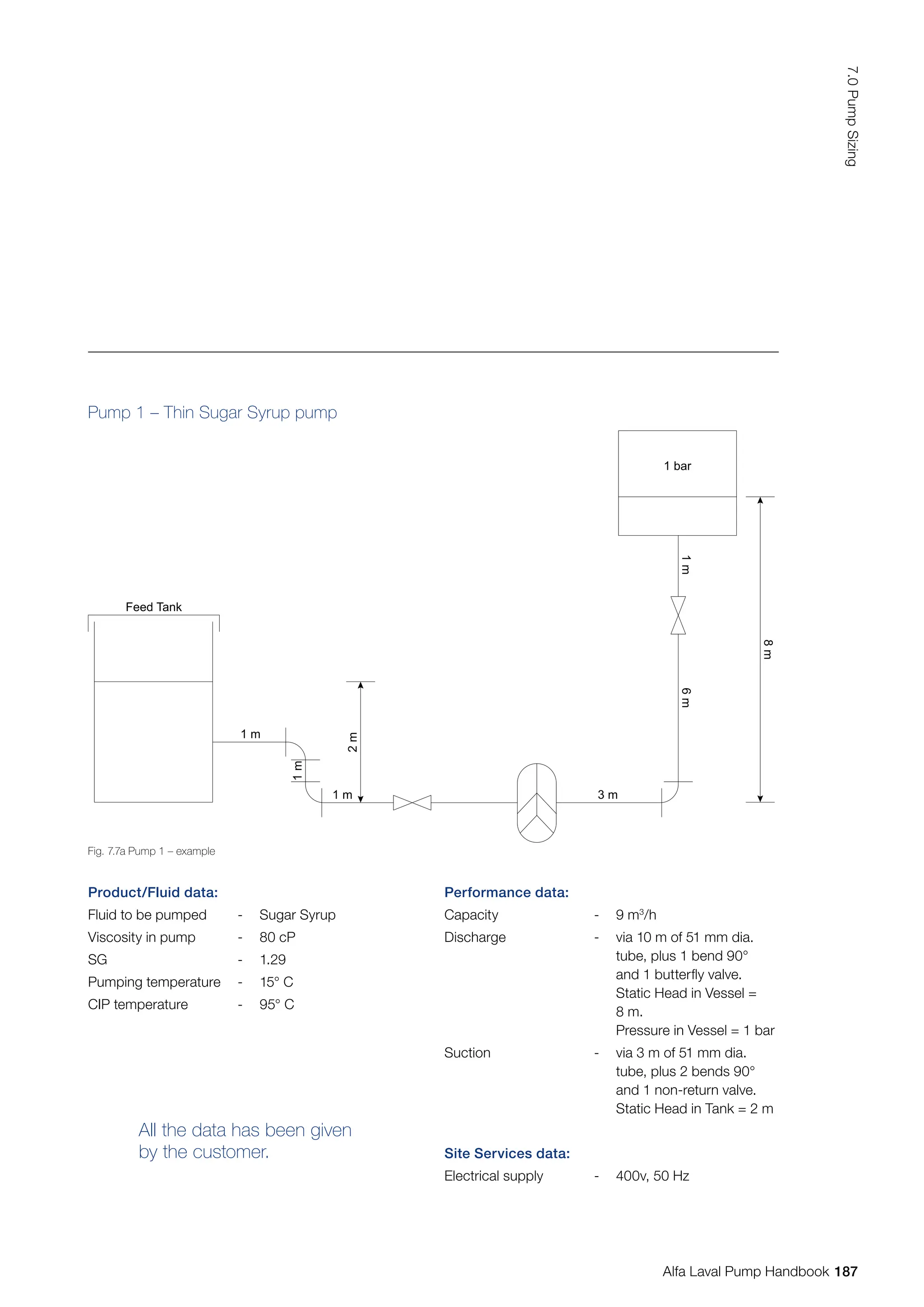
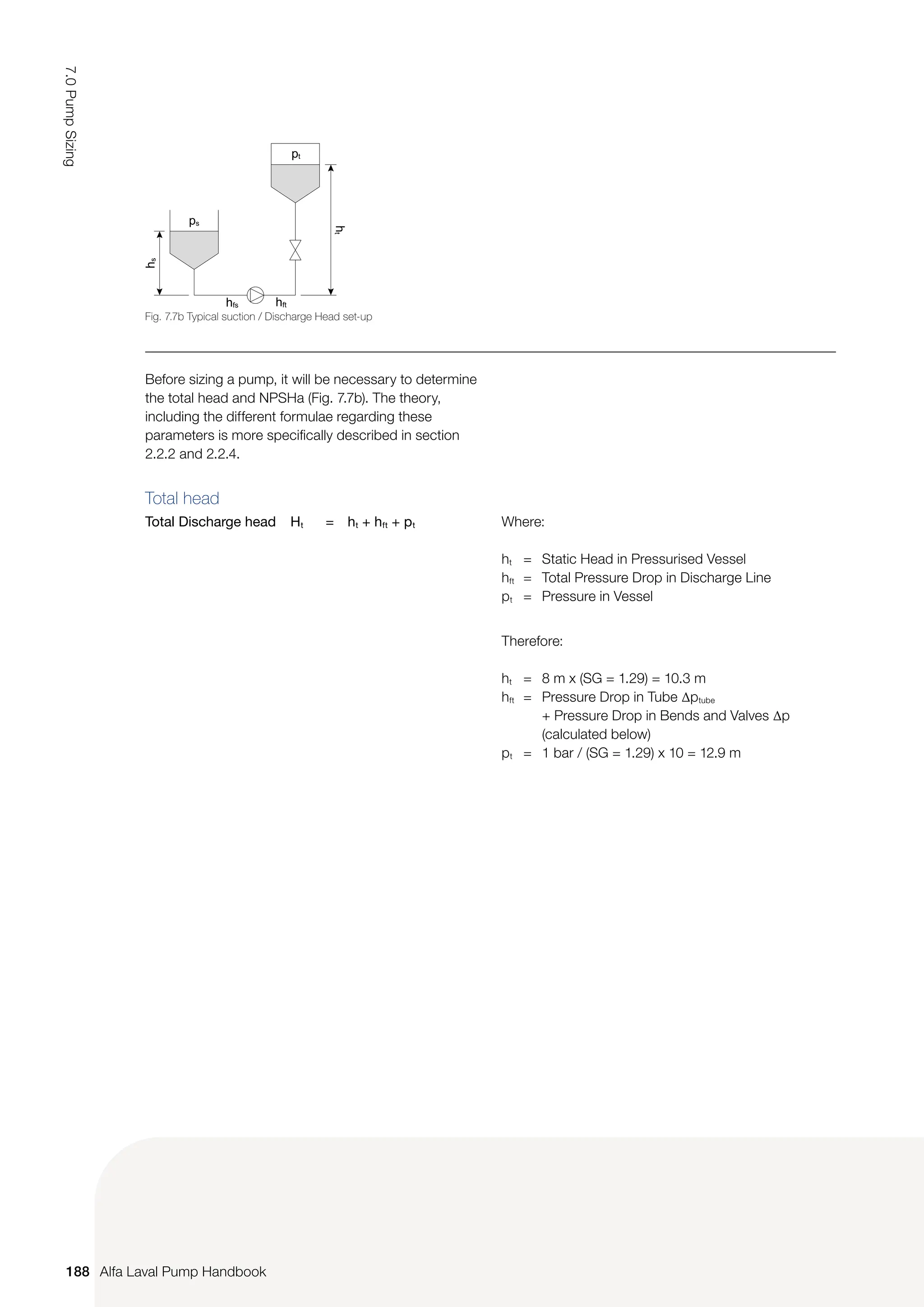
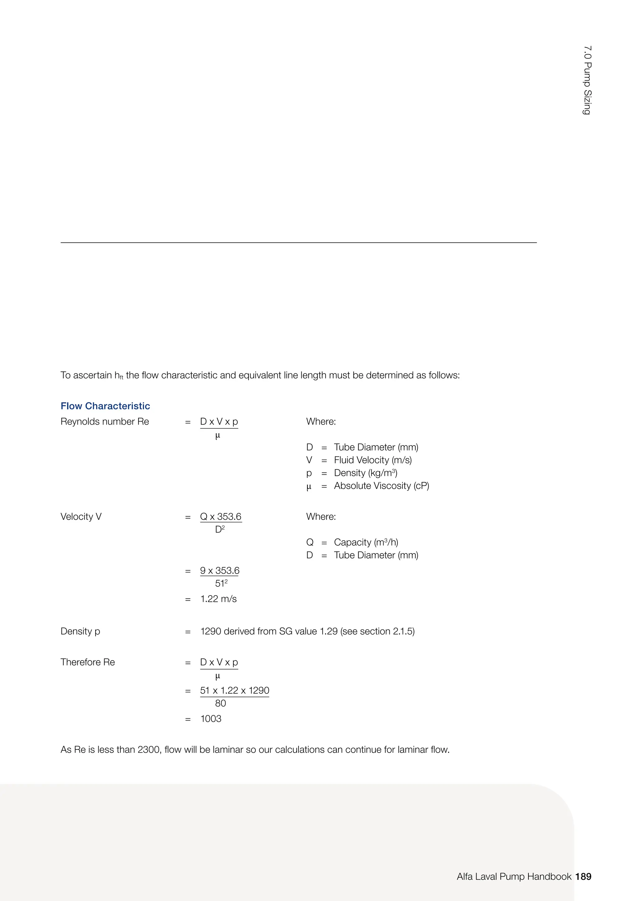
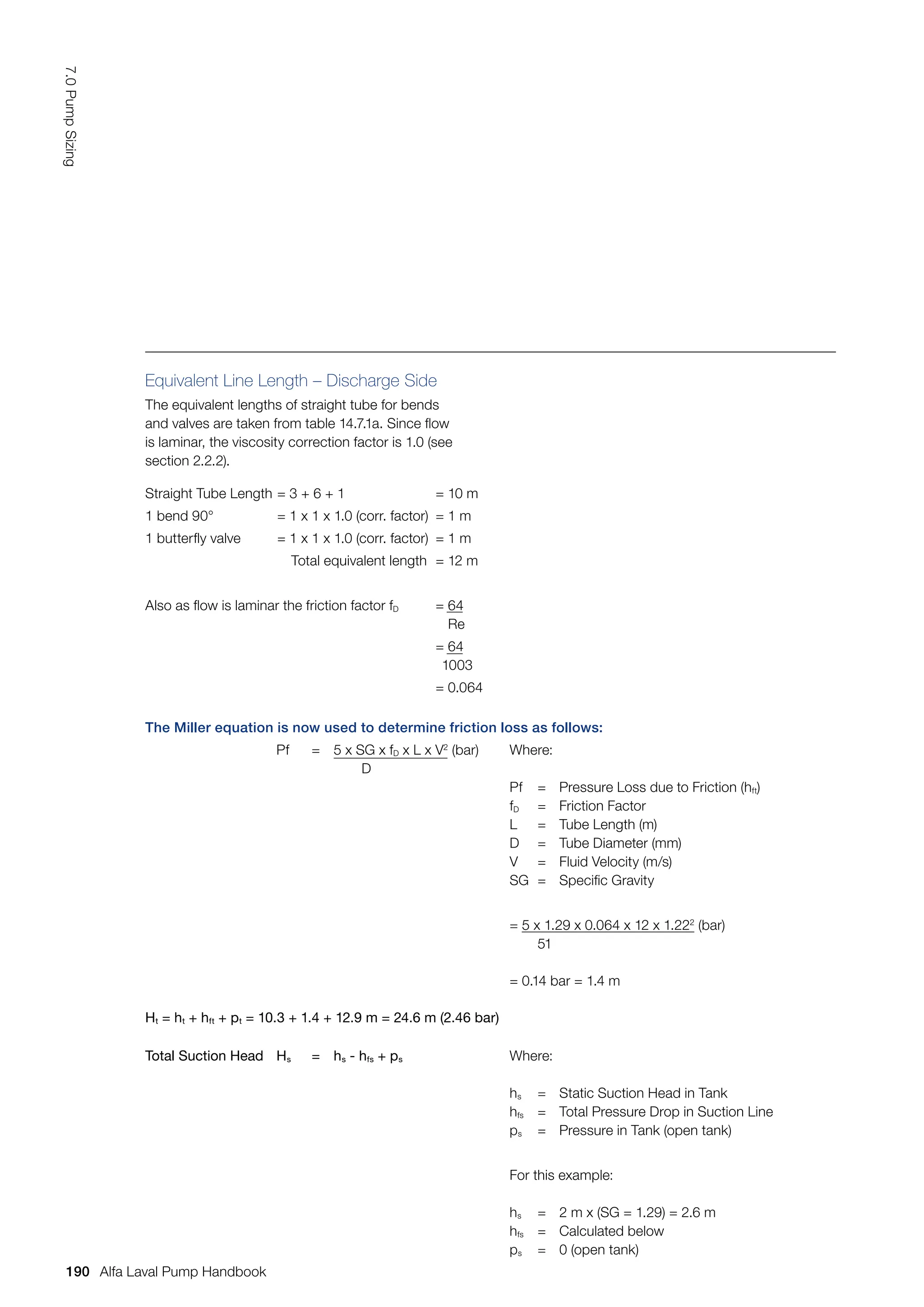
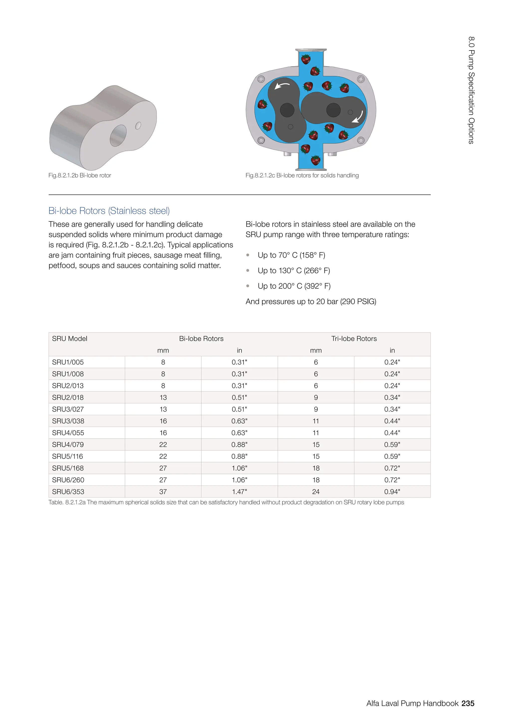
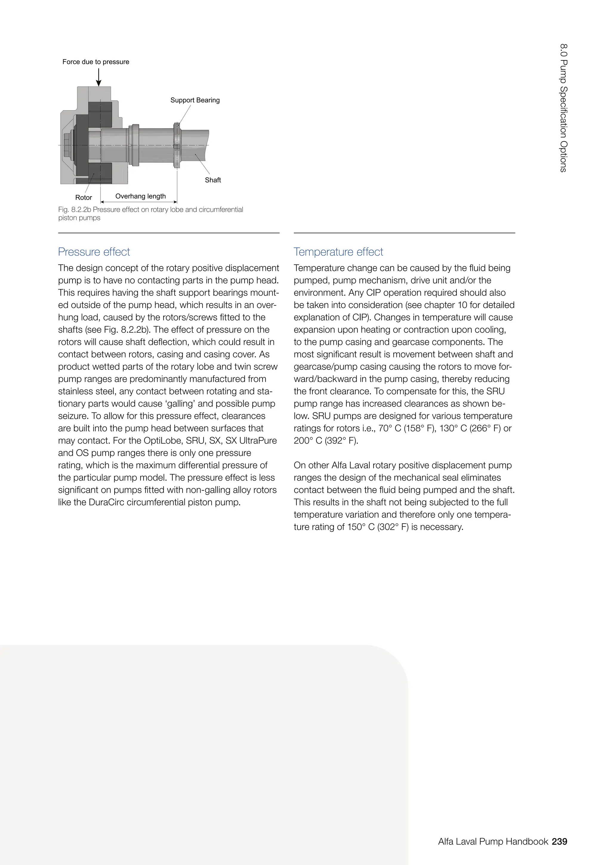
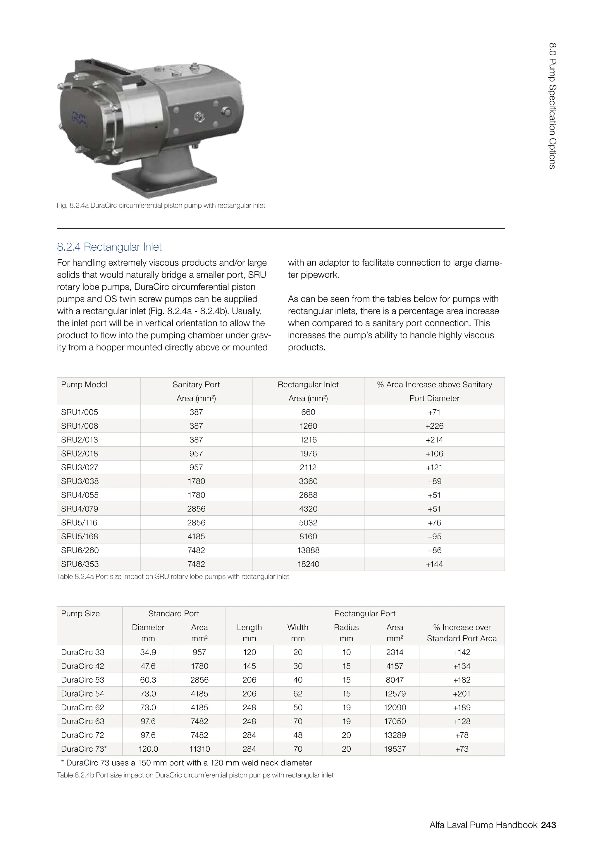
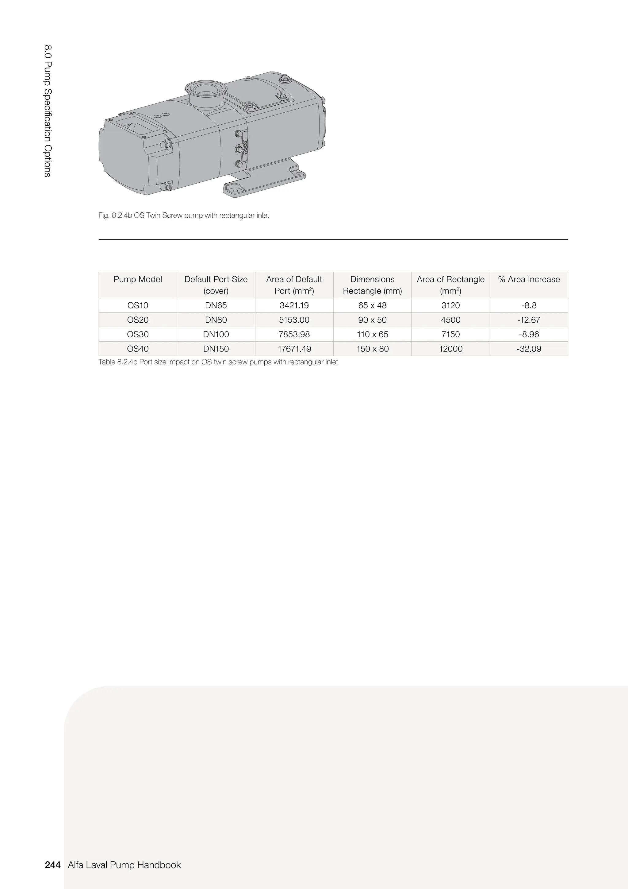
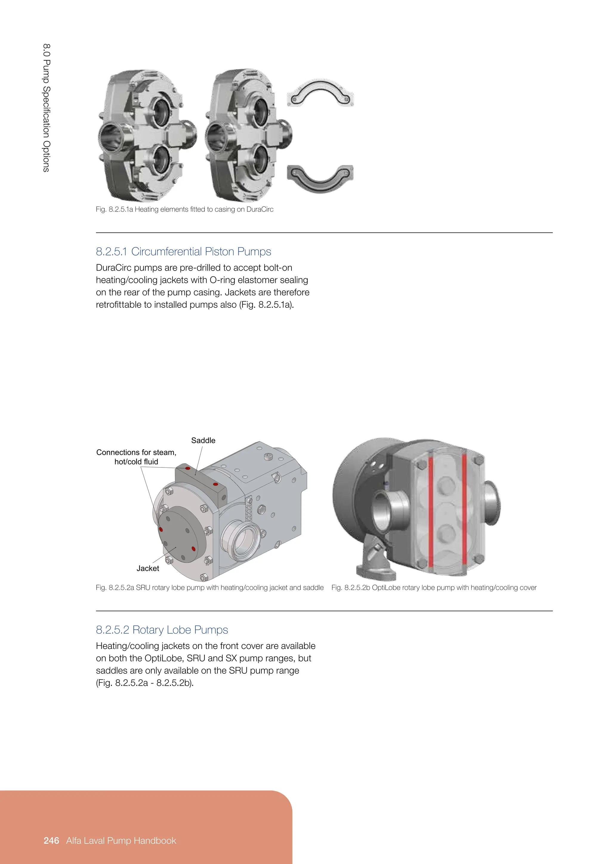
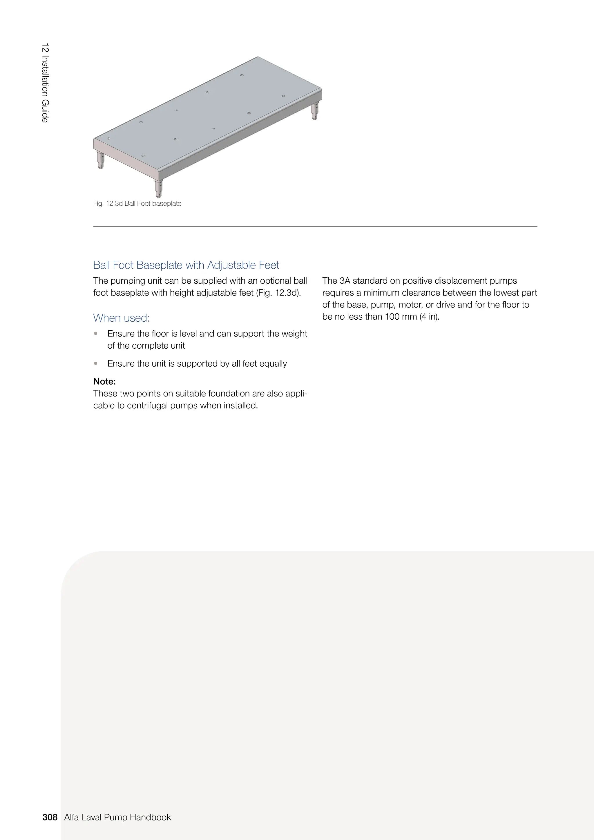
This pump handbook has been produced to support pump users at all levels, providing an invaluable reference tool. The handbook includes all the necessary information for the correct selection and successful application of the Alfa Laval ranges of Centrifugal, Liquid Ring, and Rotary Lobe Pumps.


