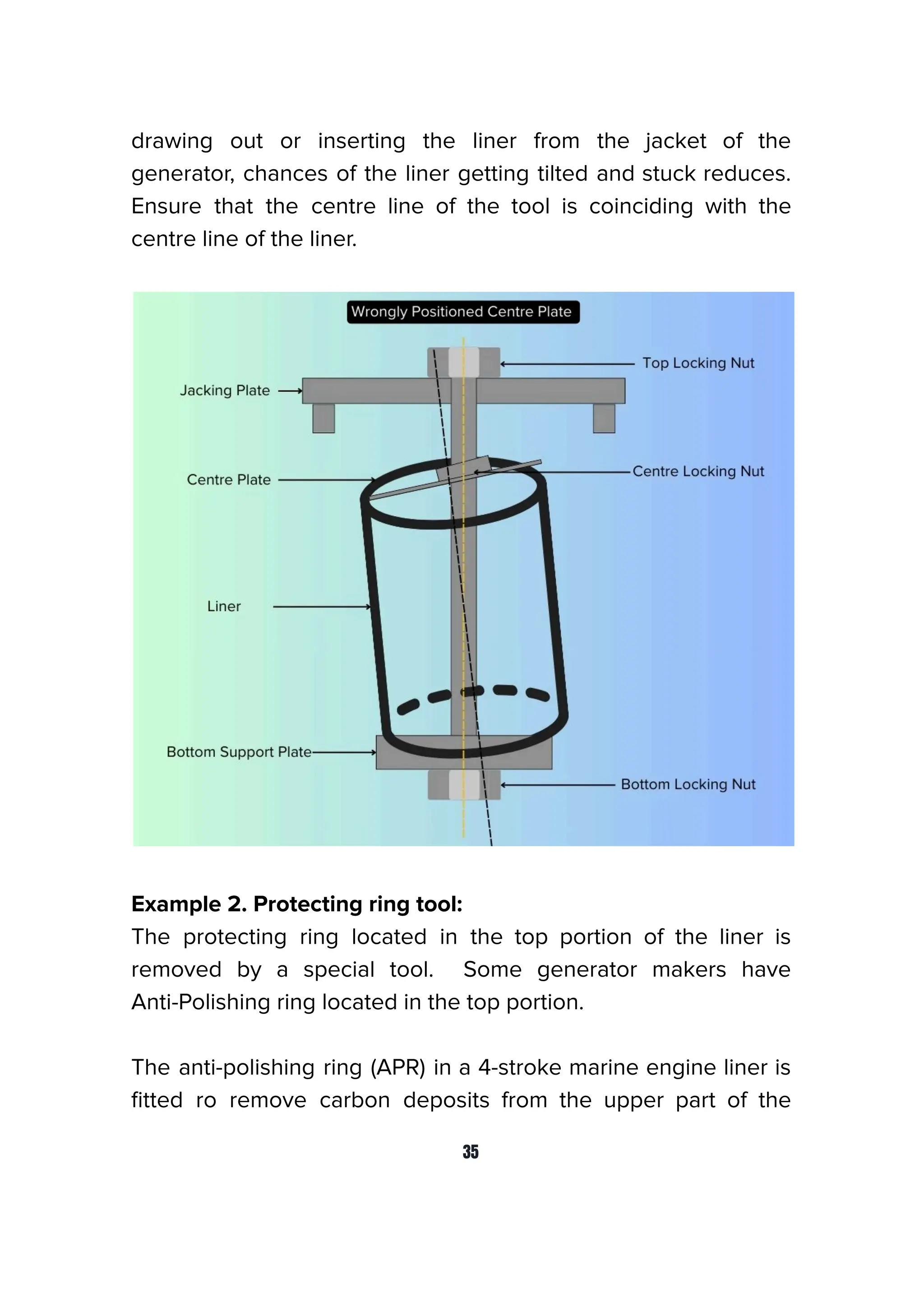
Download to read offline


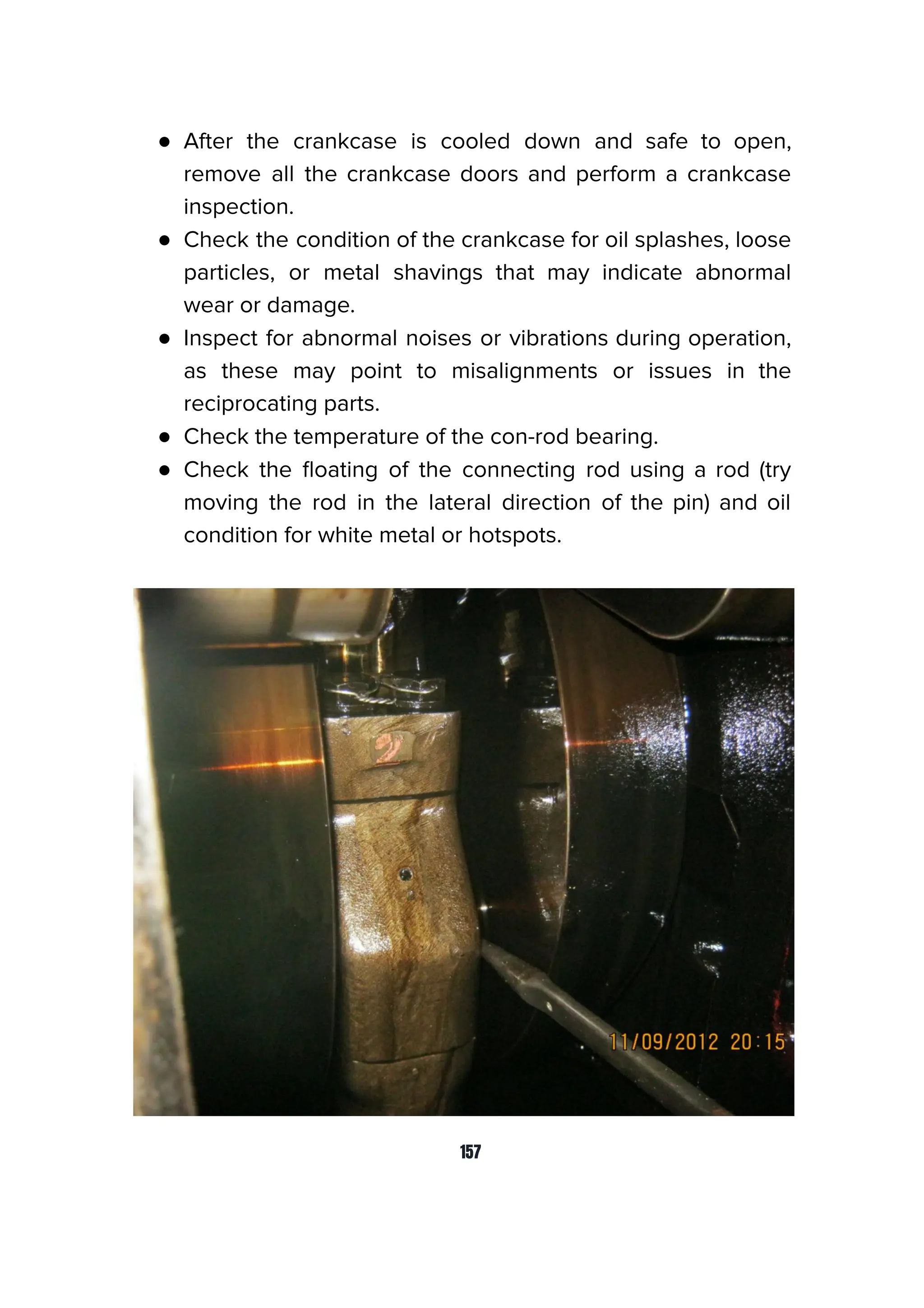


In this second edition of the book, we have included updated practices, enhanced diagrams, and step-by-step instructions to address modern challenges encountered during generator overhauls. We have also expanded the troubleshooting section, providing clearer explanations and detailed diagnostic steps to help engineers confidently address unexpected issues during overhauls. Understanding that time is critical aboard a vessel, this edition emphasizes efficient planning, teamwork, and safety measures to ensure successful overhauls in even the most challenging conditions. Fair winds and smooth seas.


