Downloaded 496 times
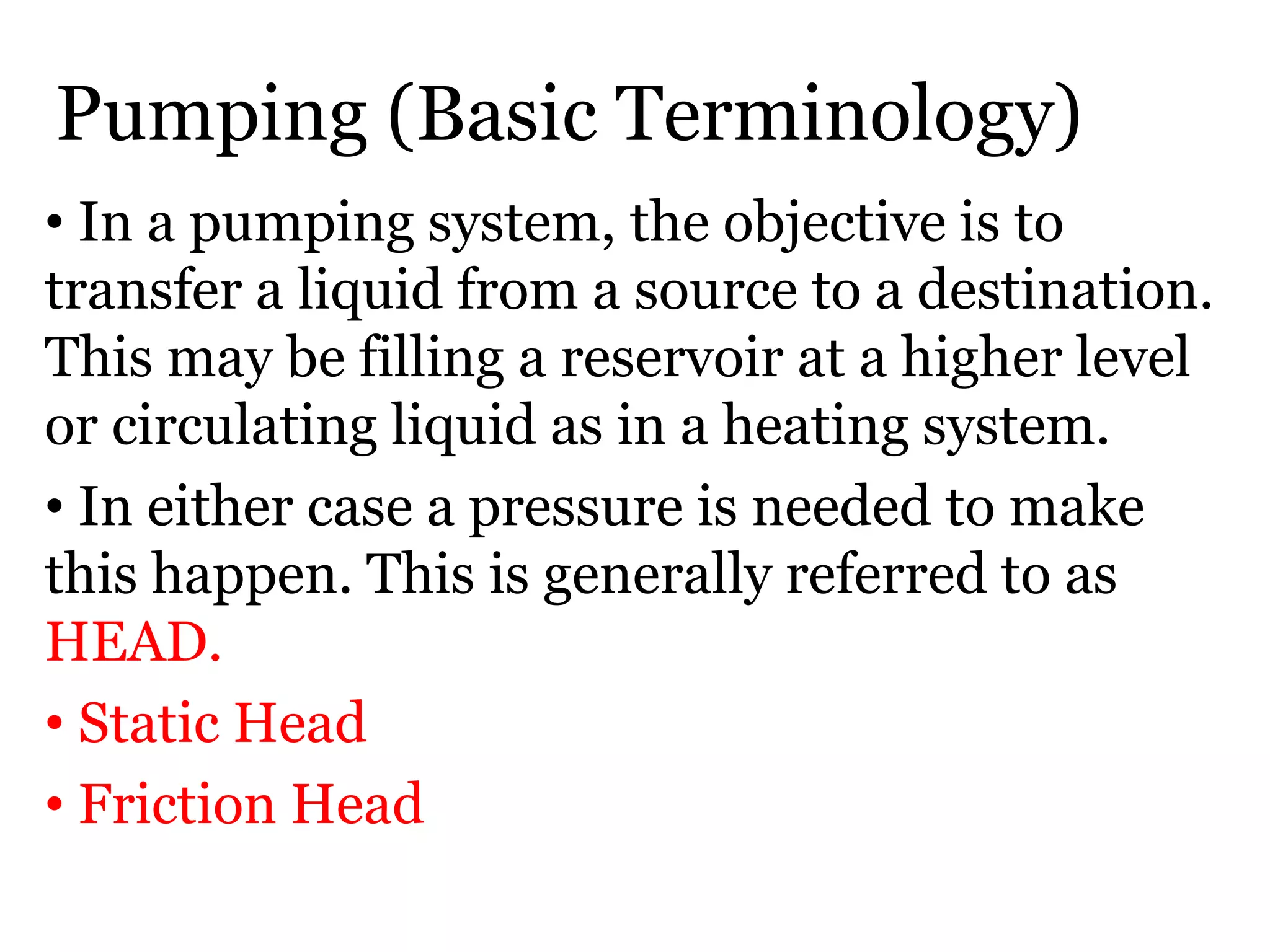
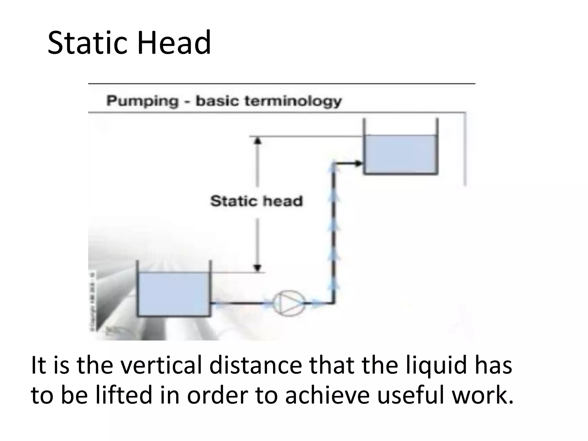
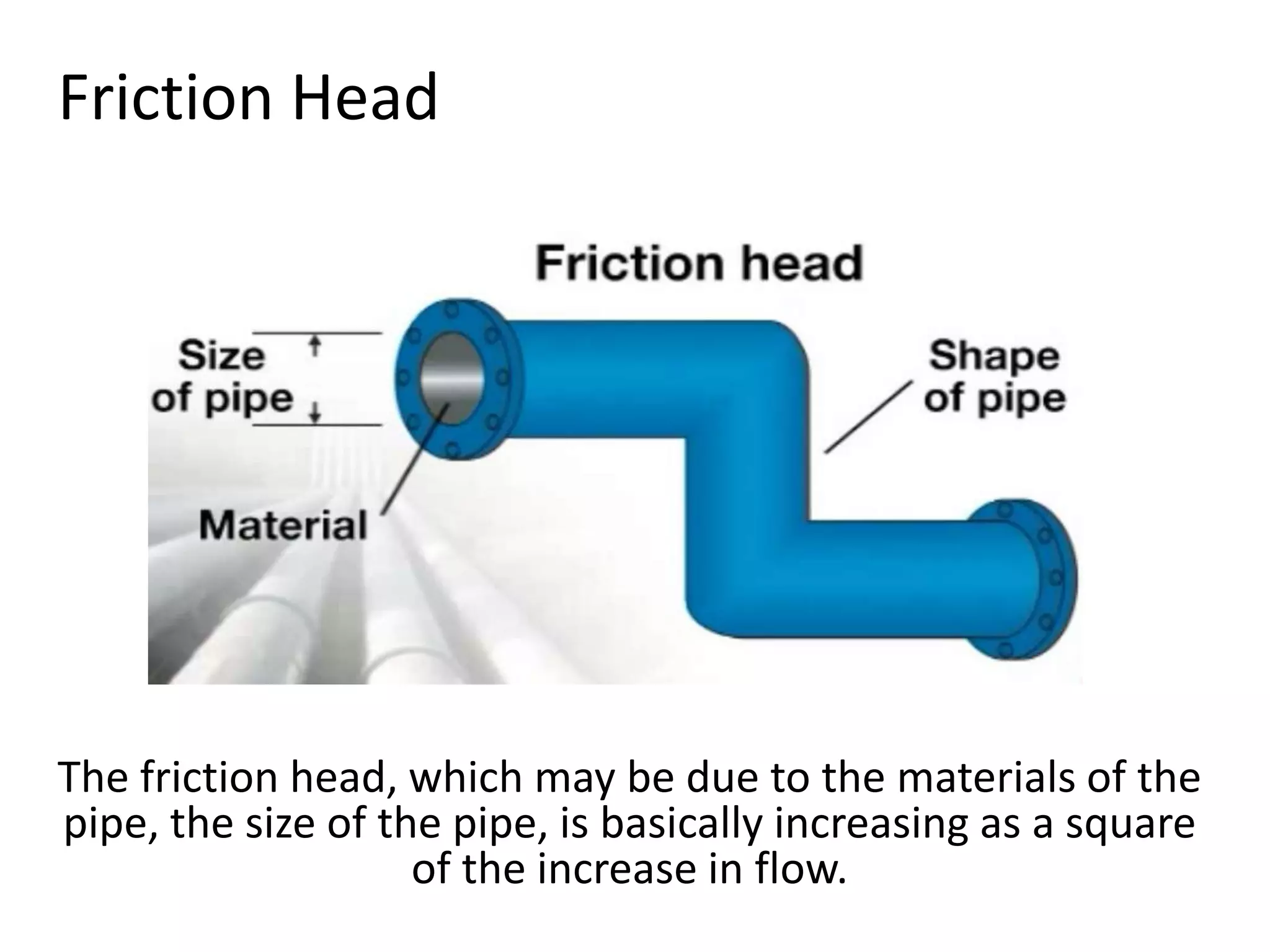
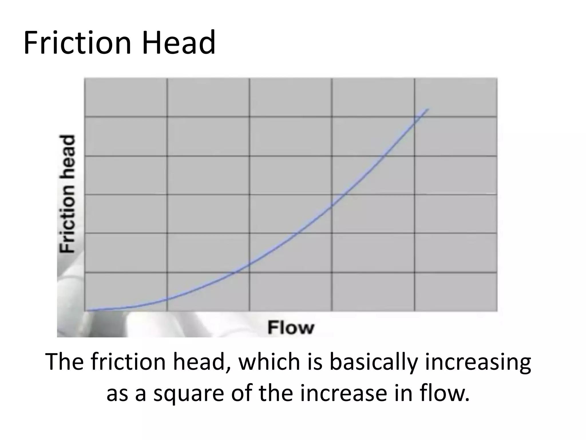
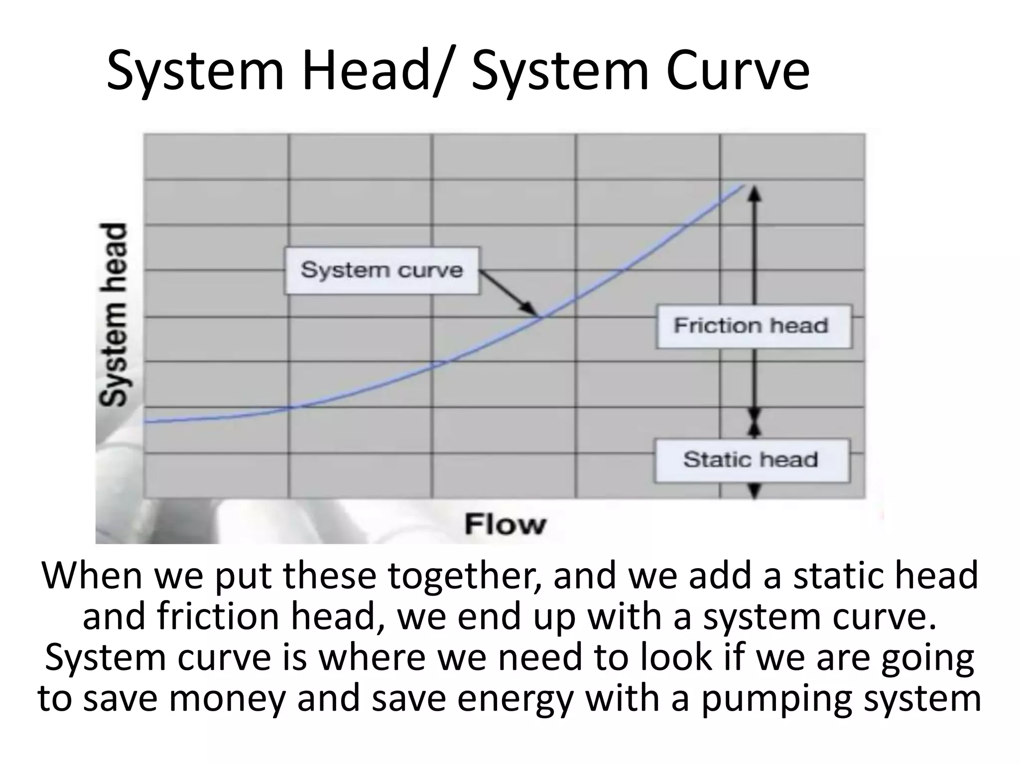
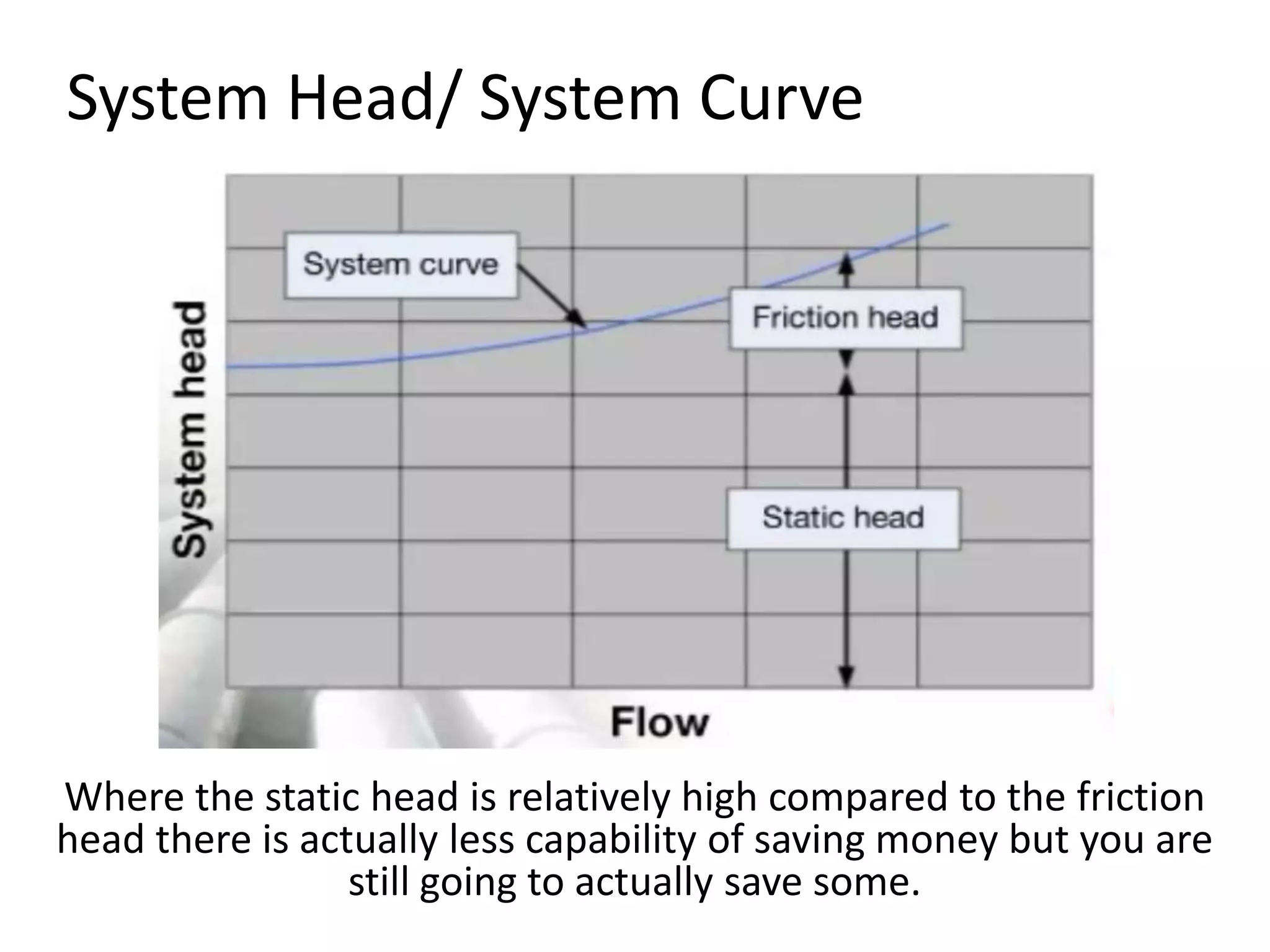
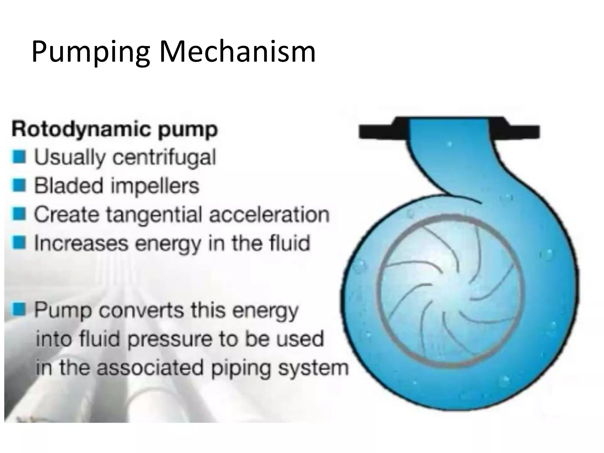
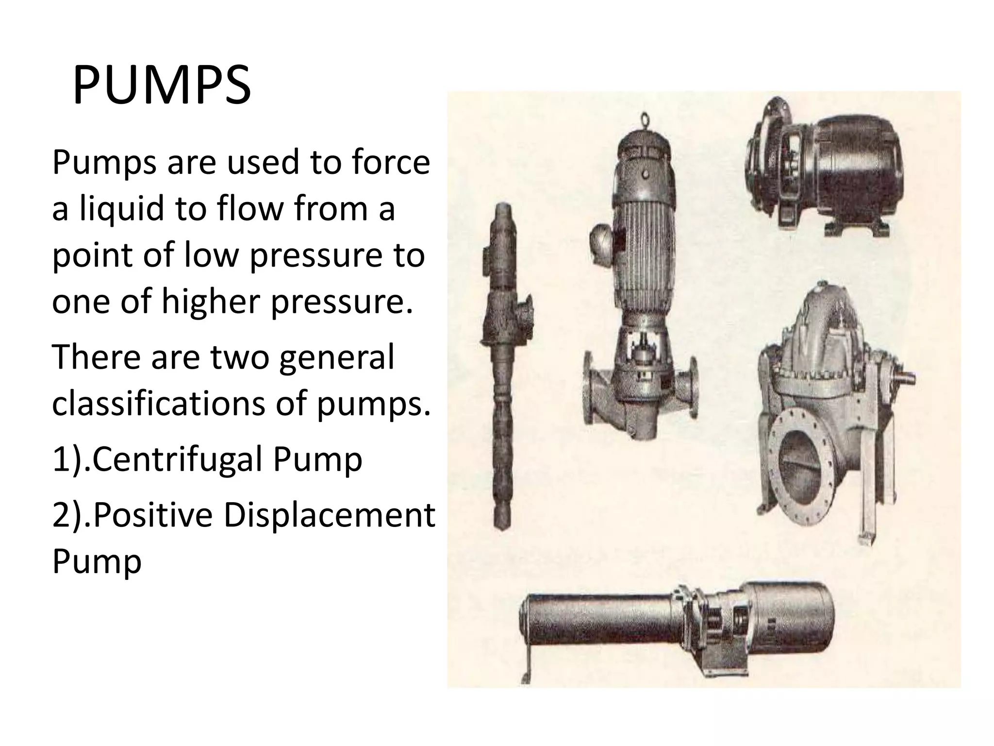
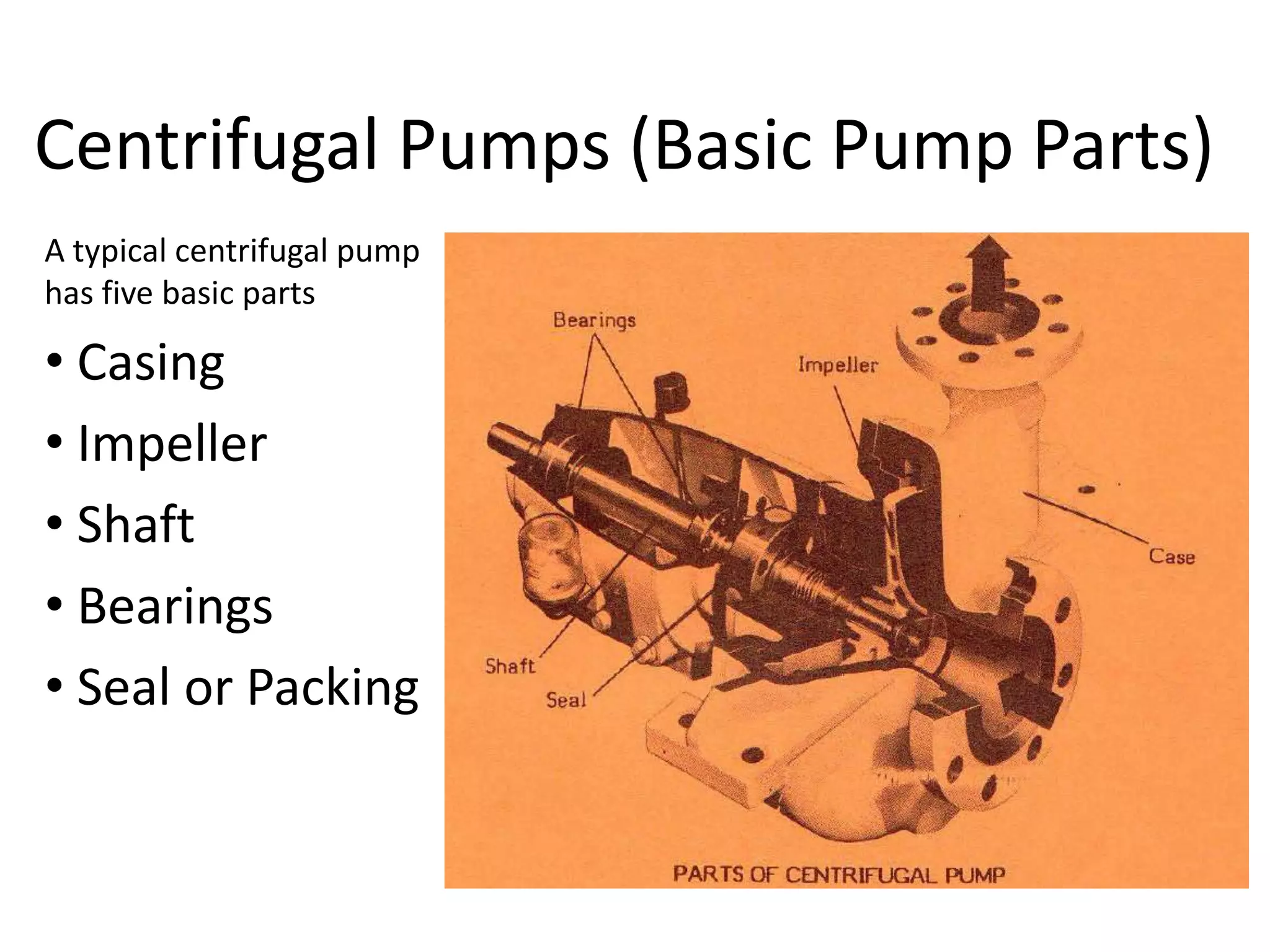
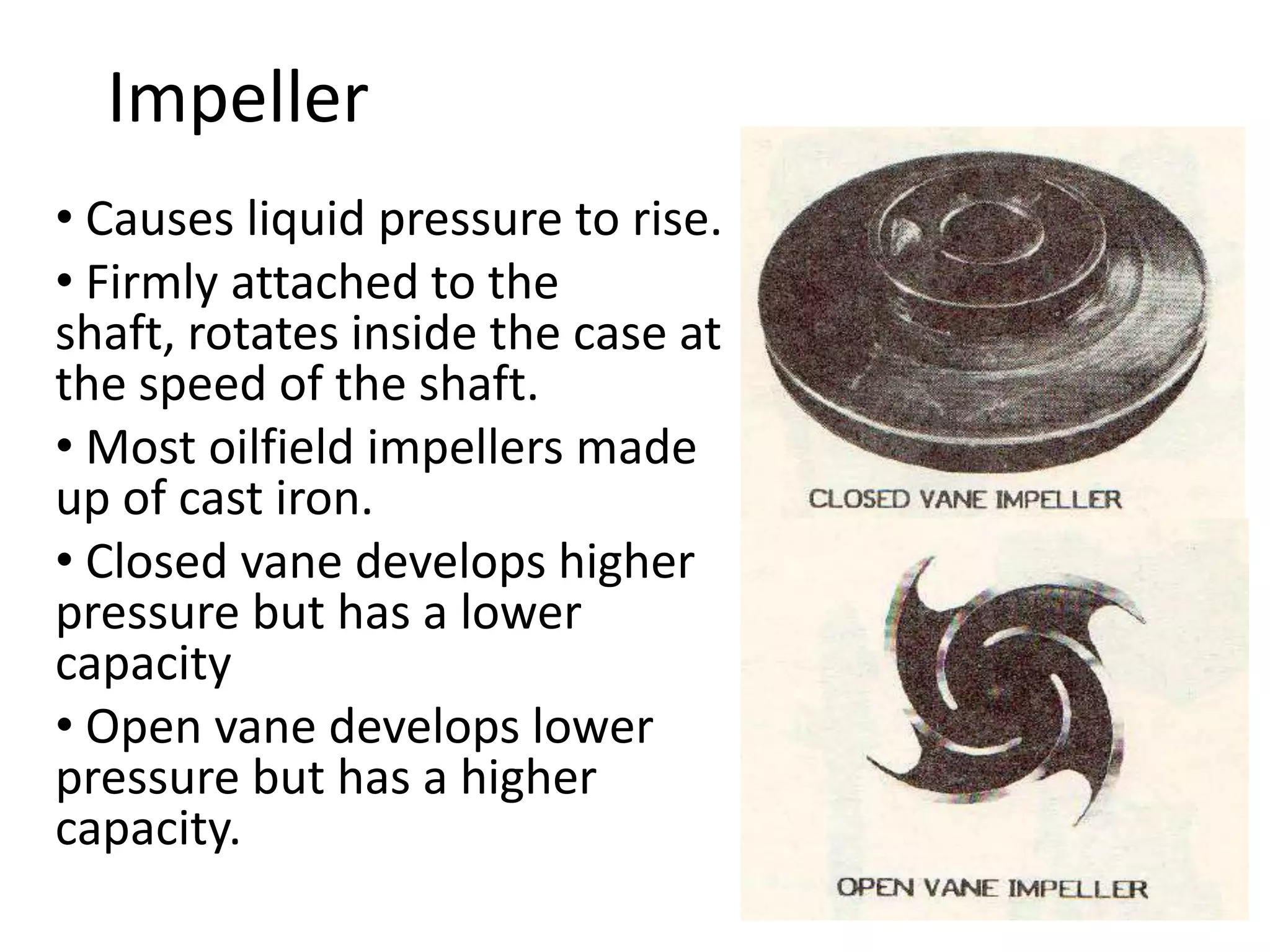
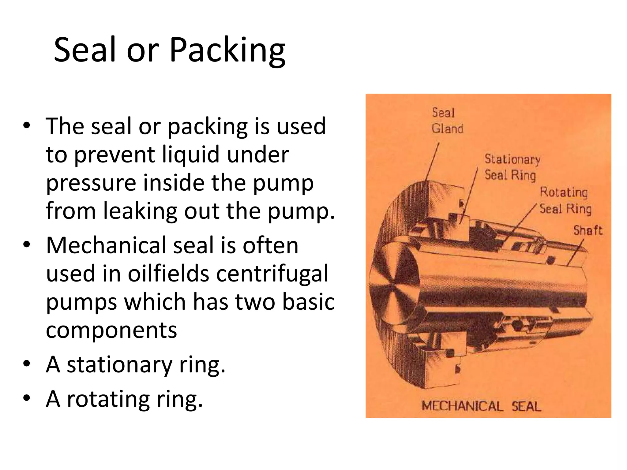
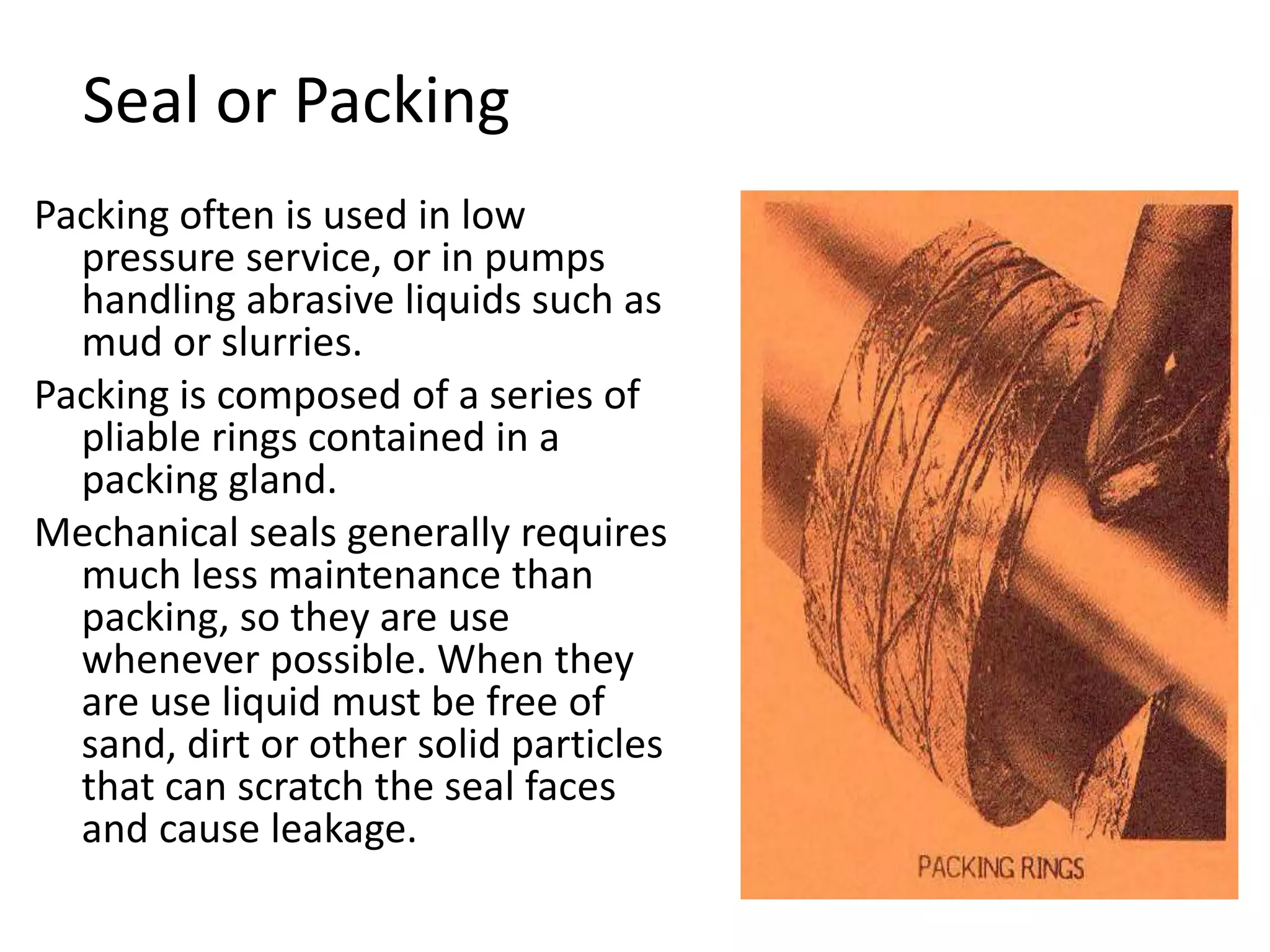
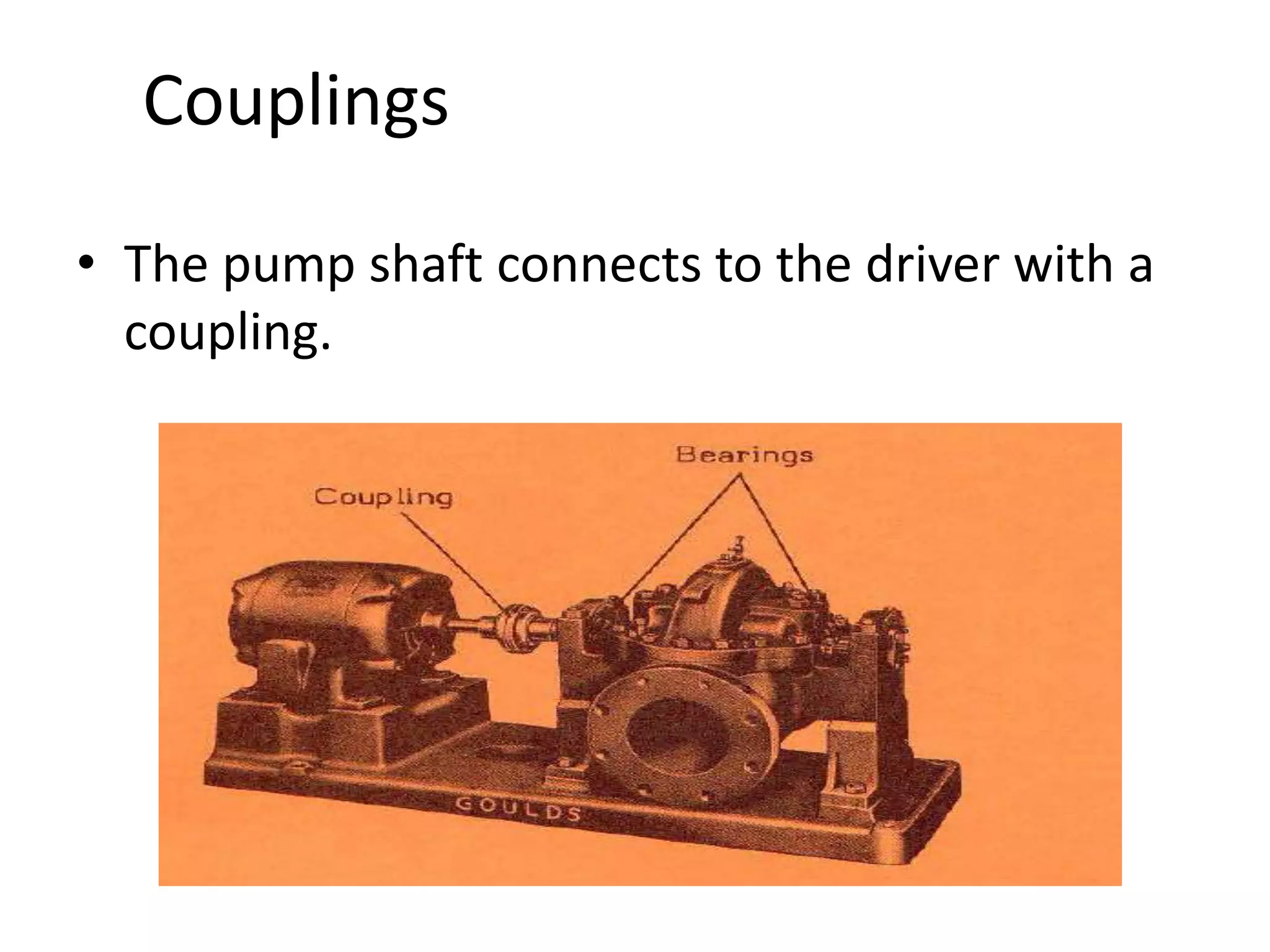
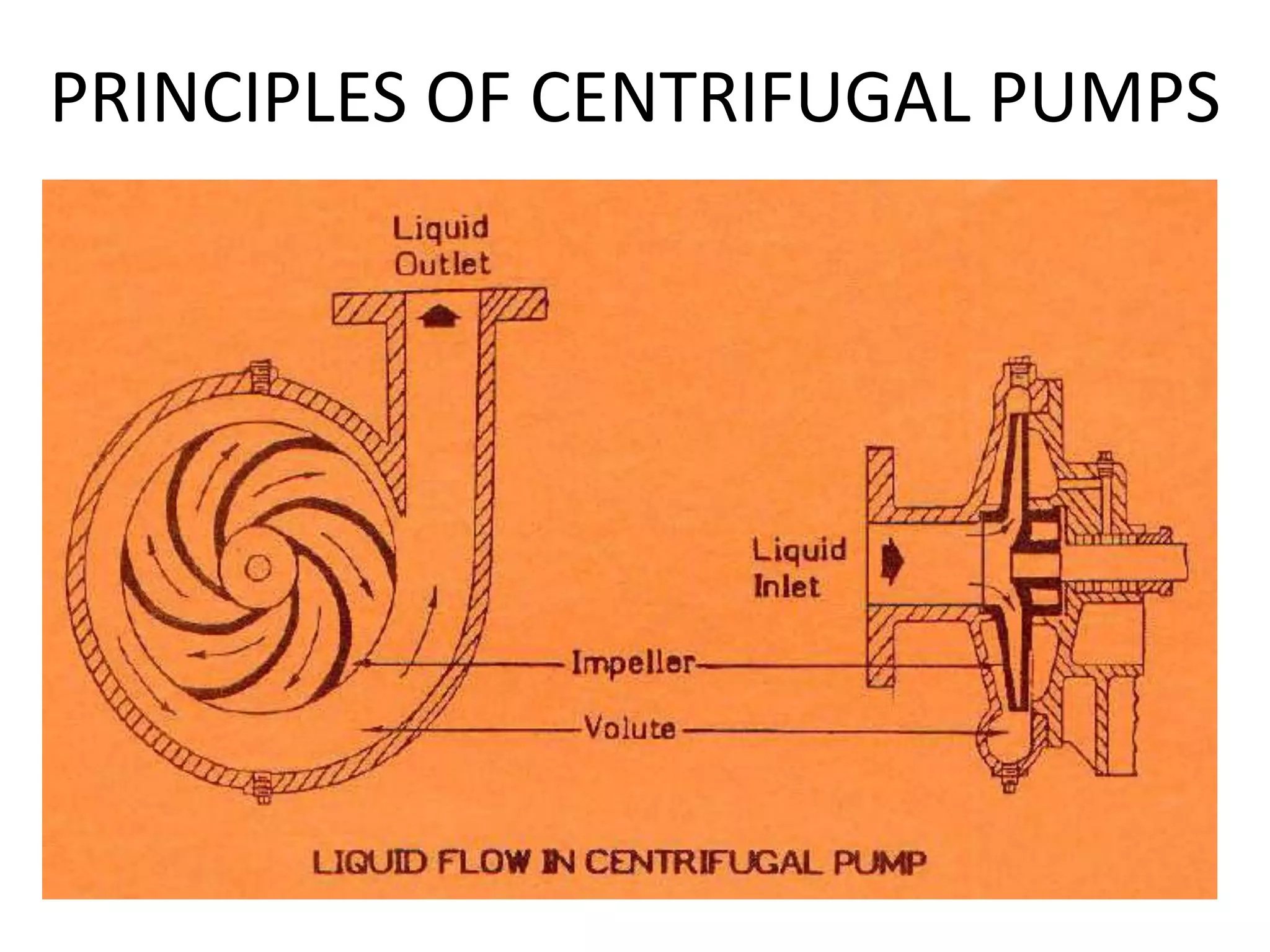
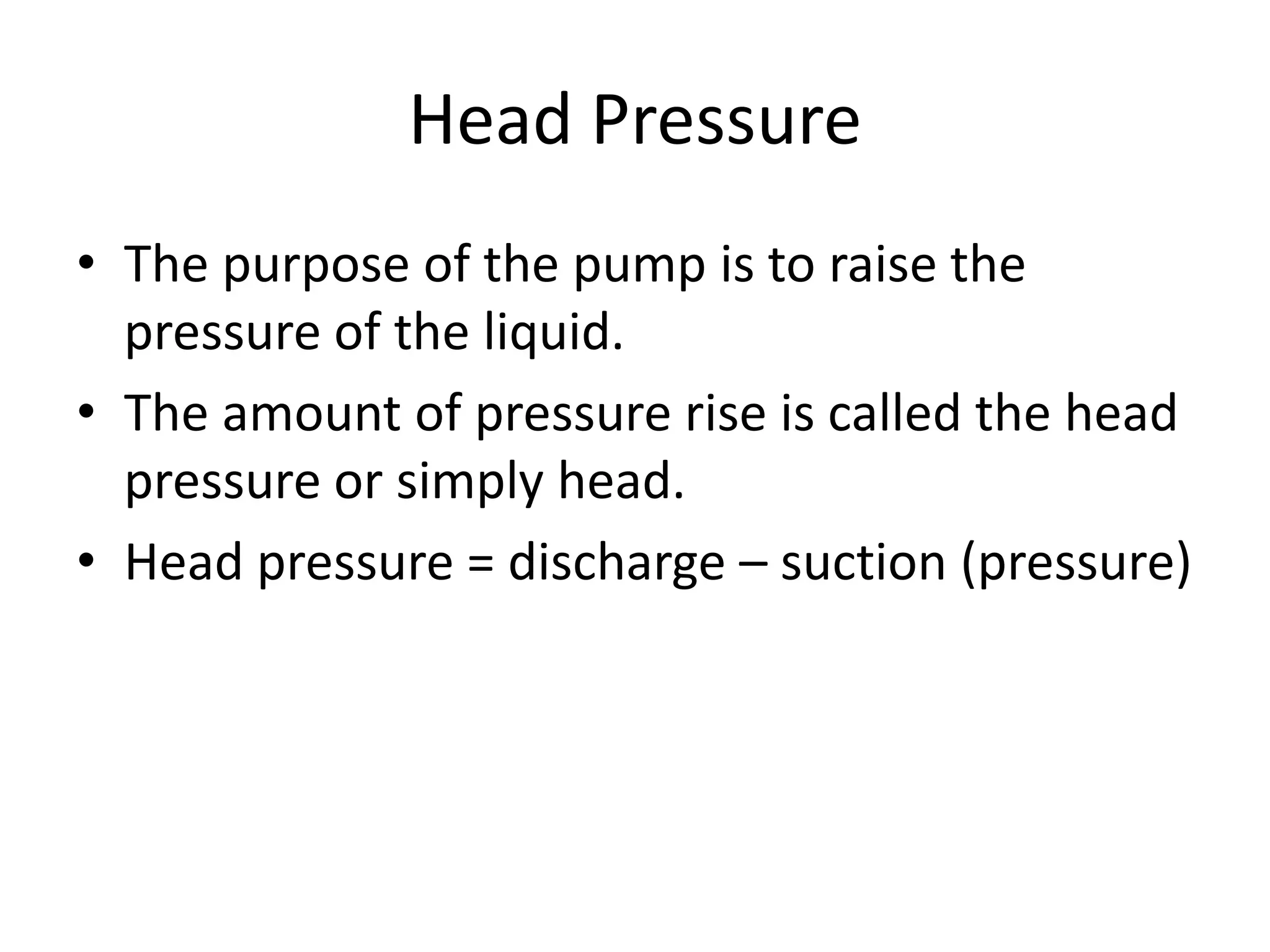
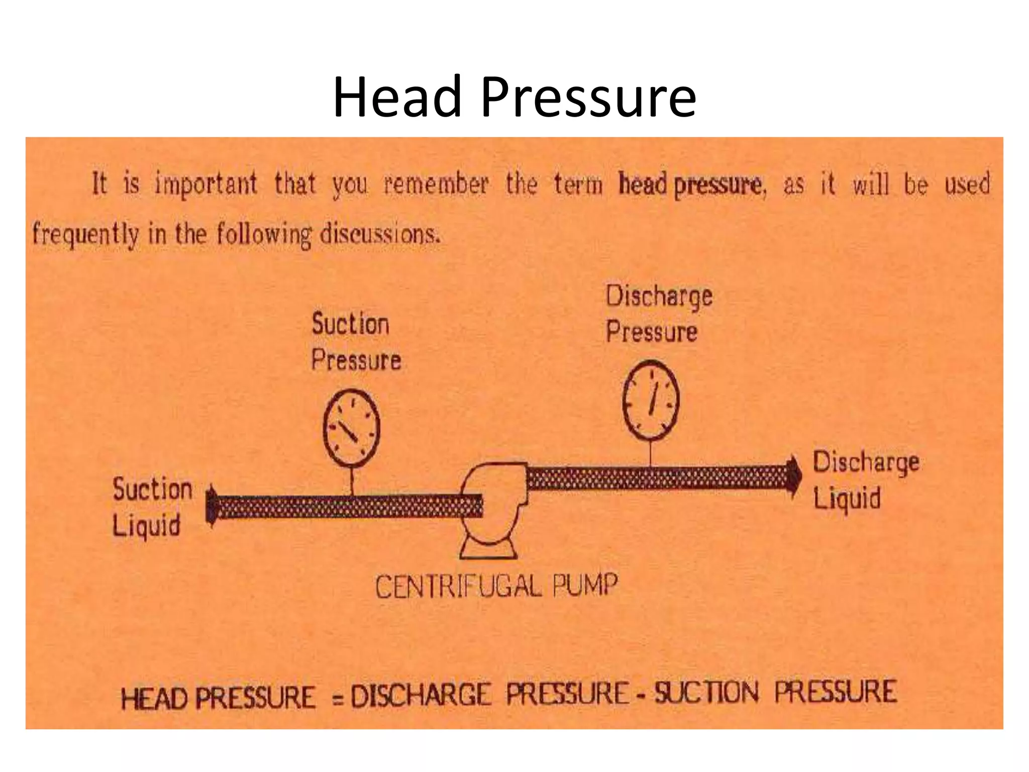
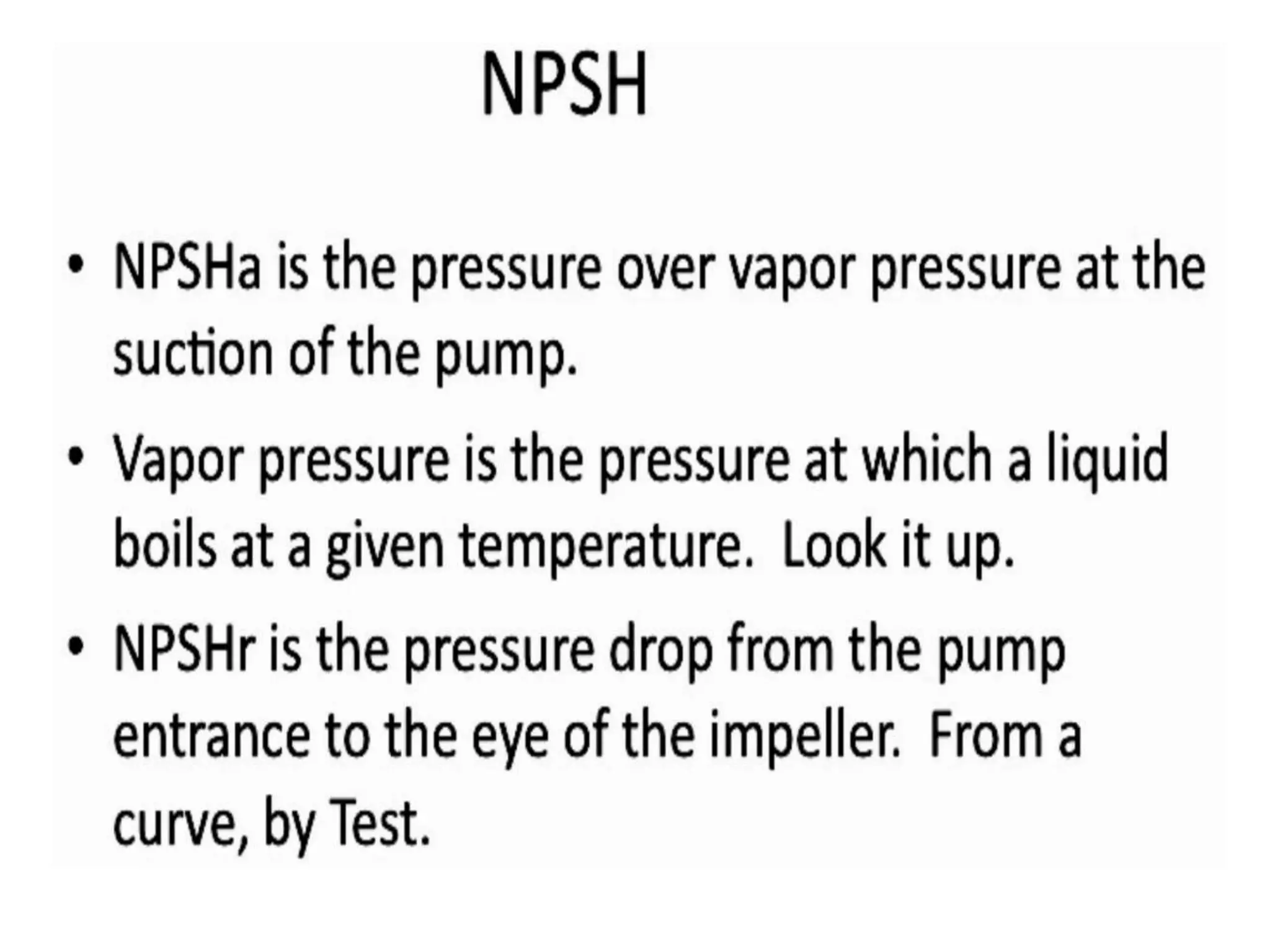
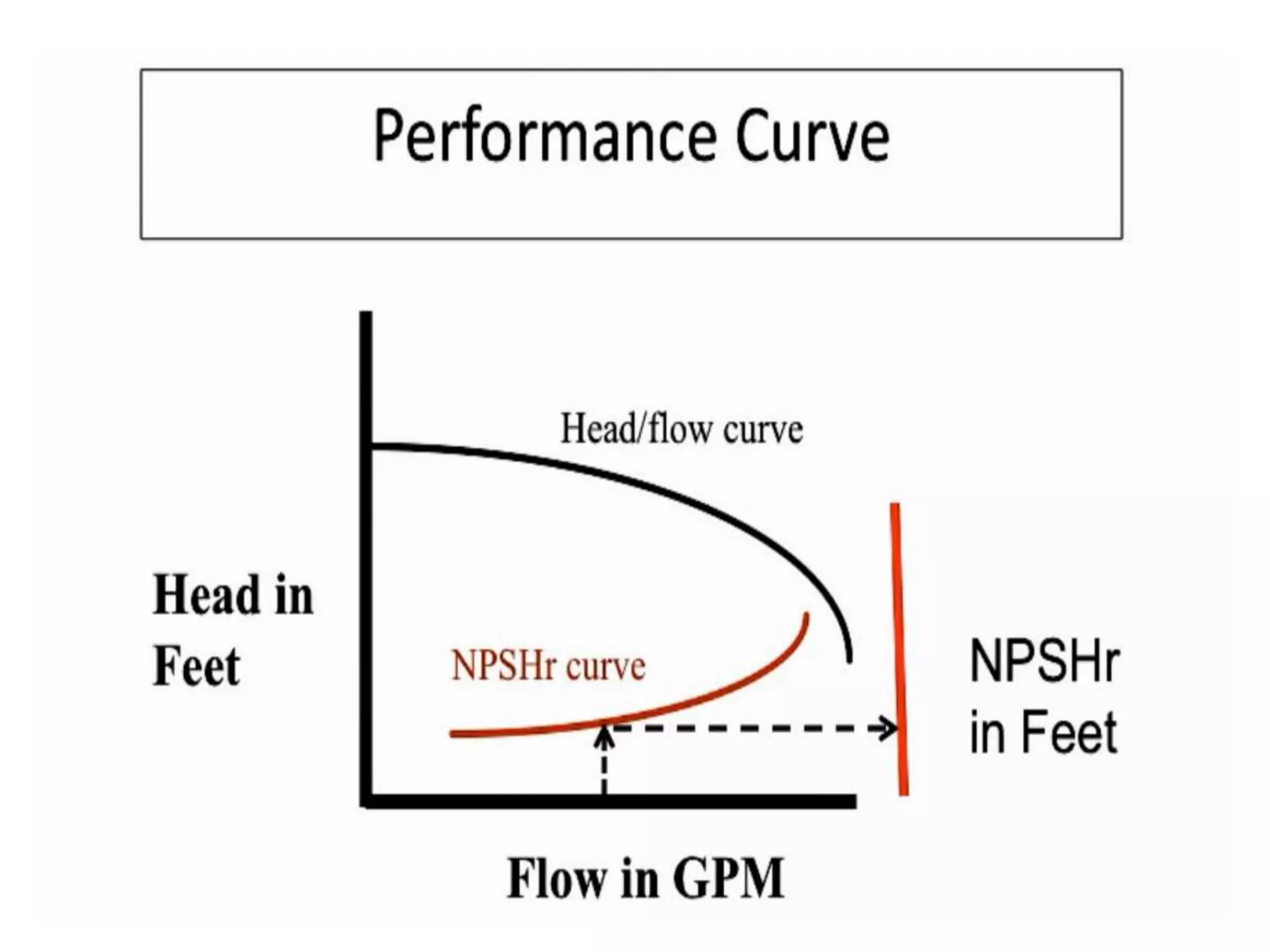
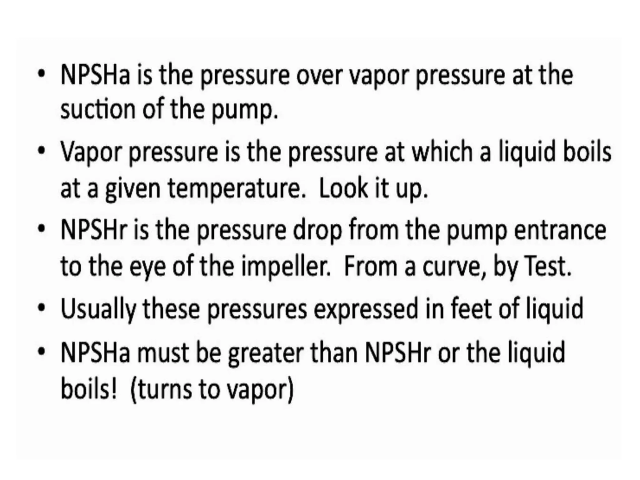
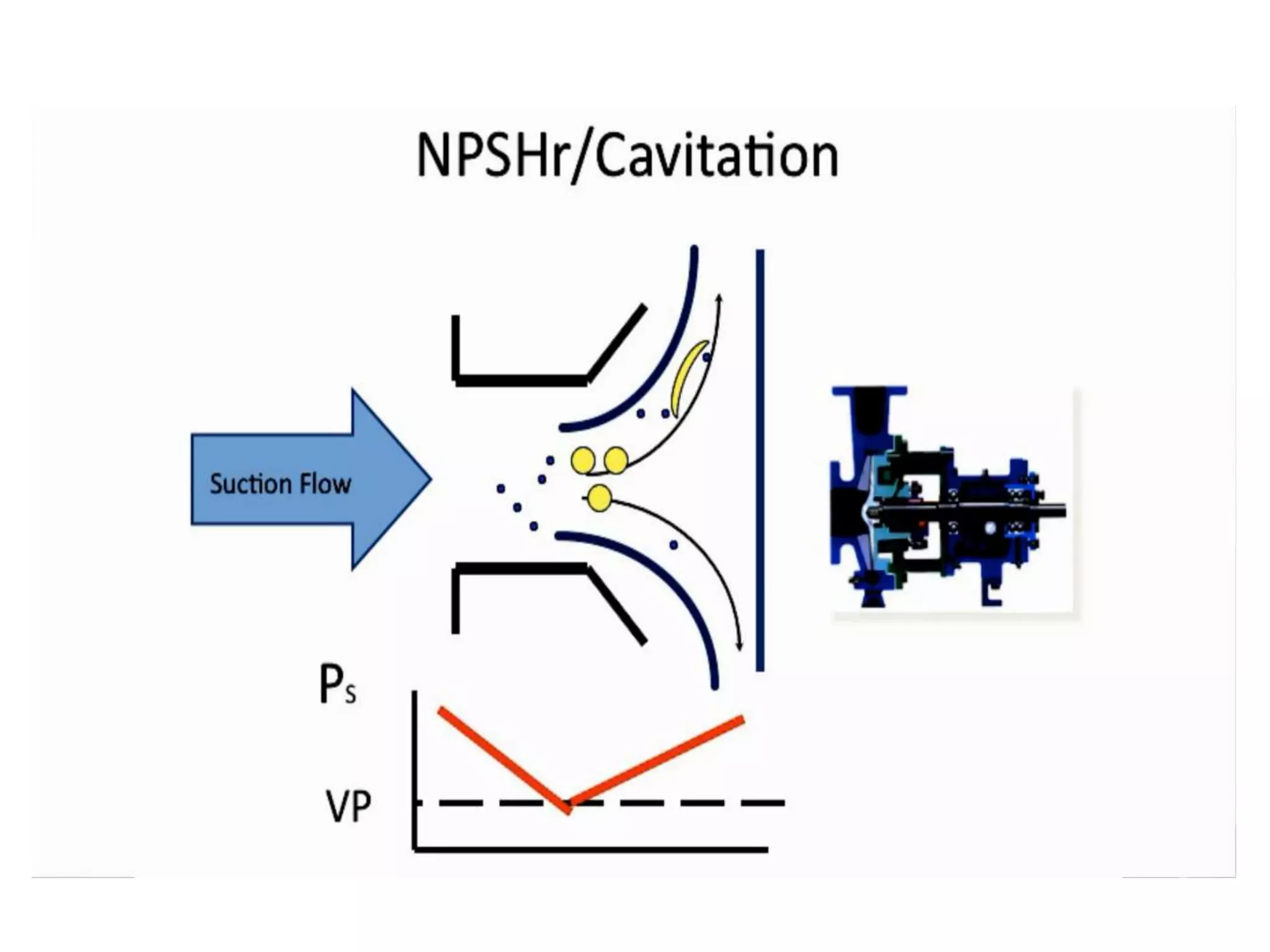
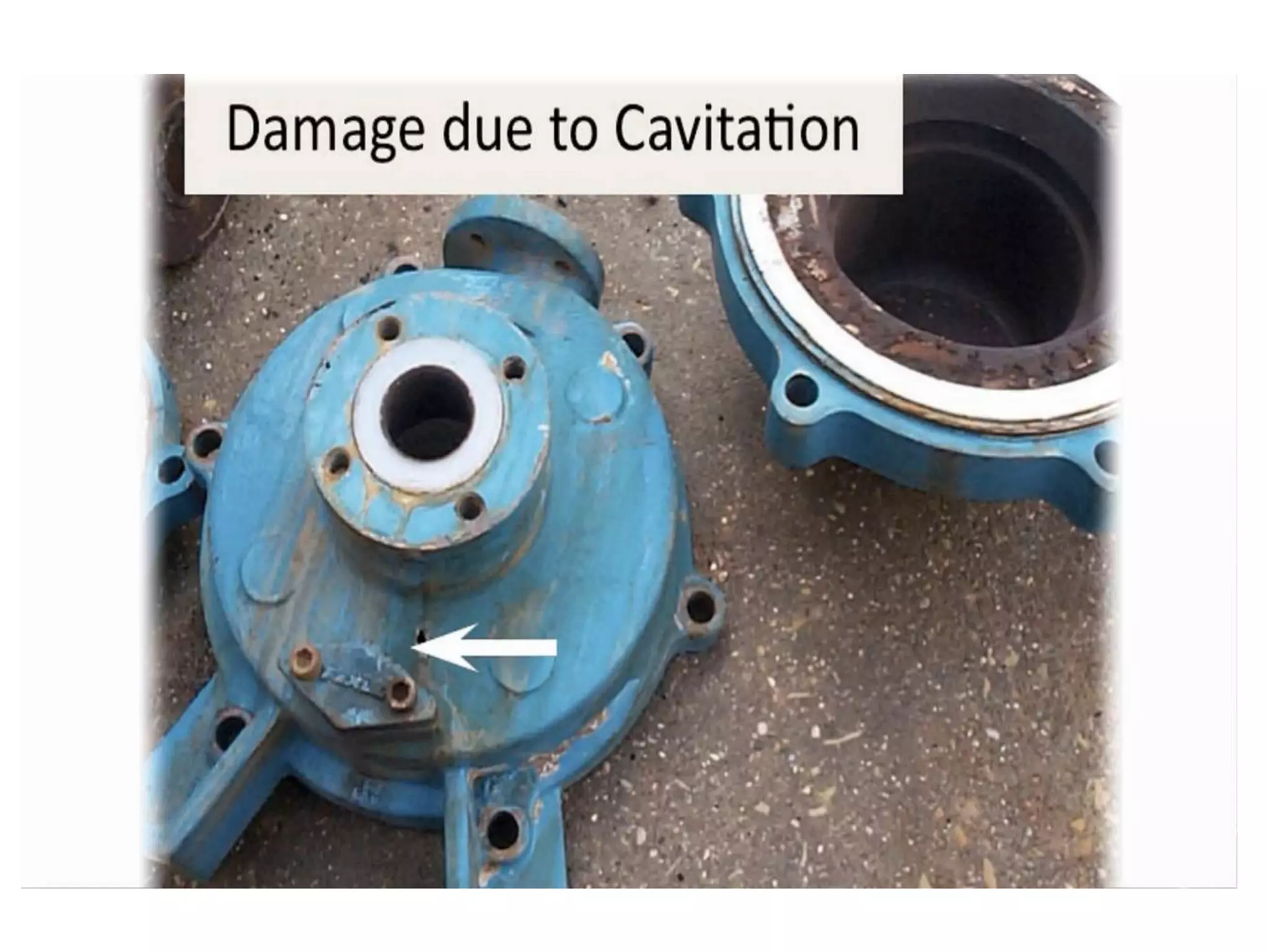
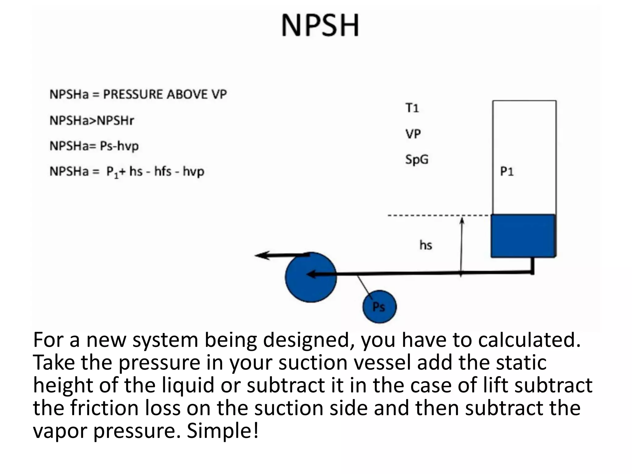
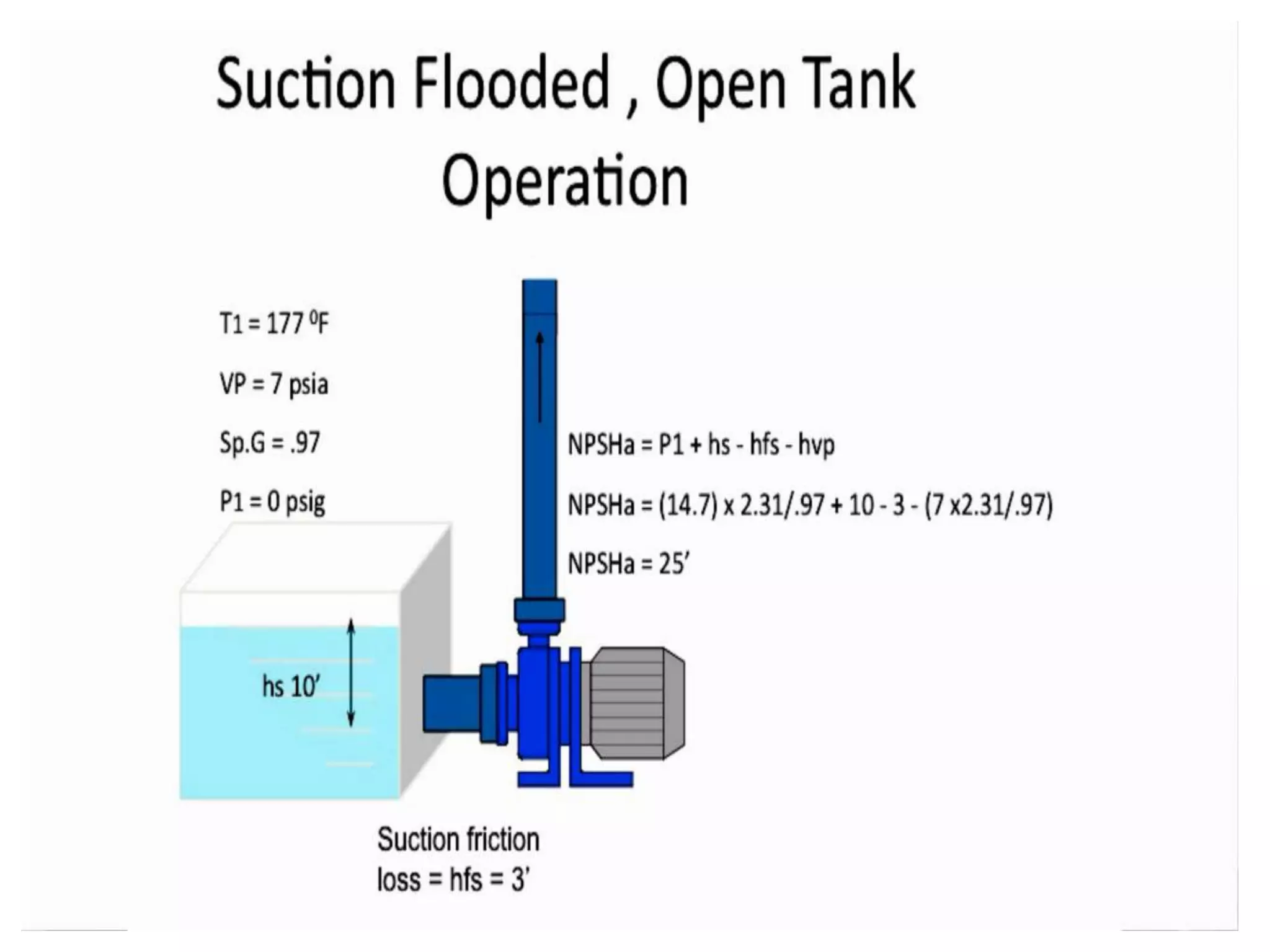
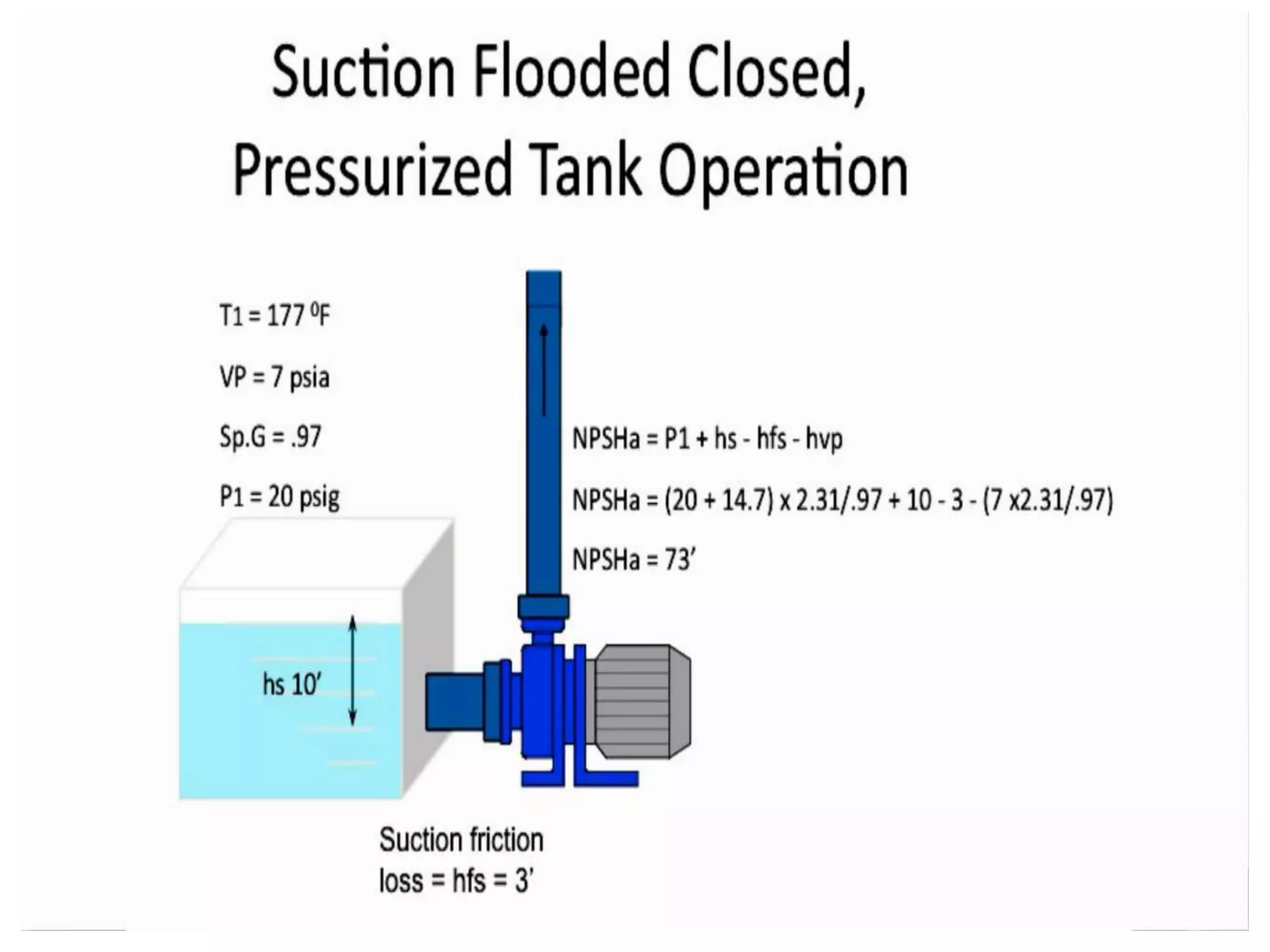
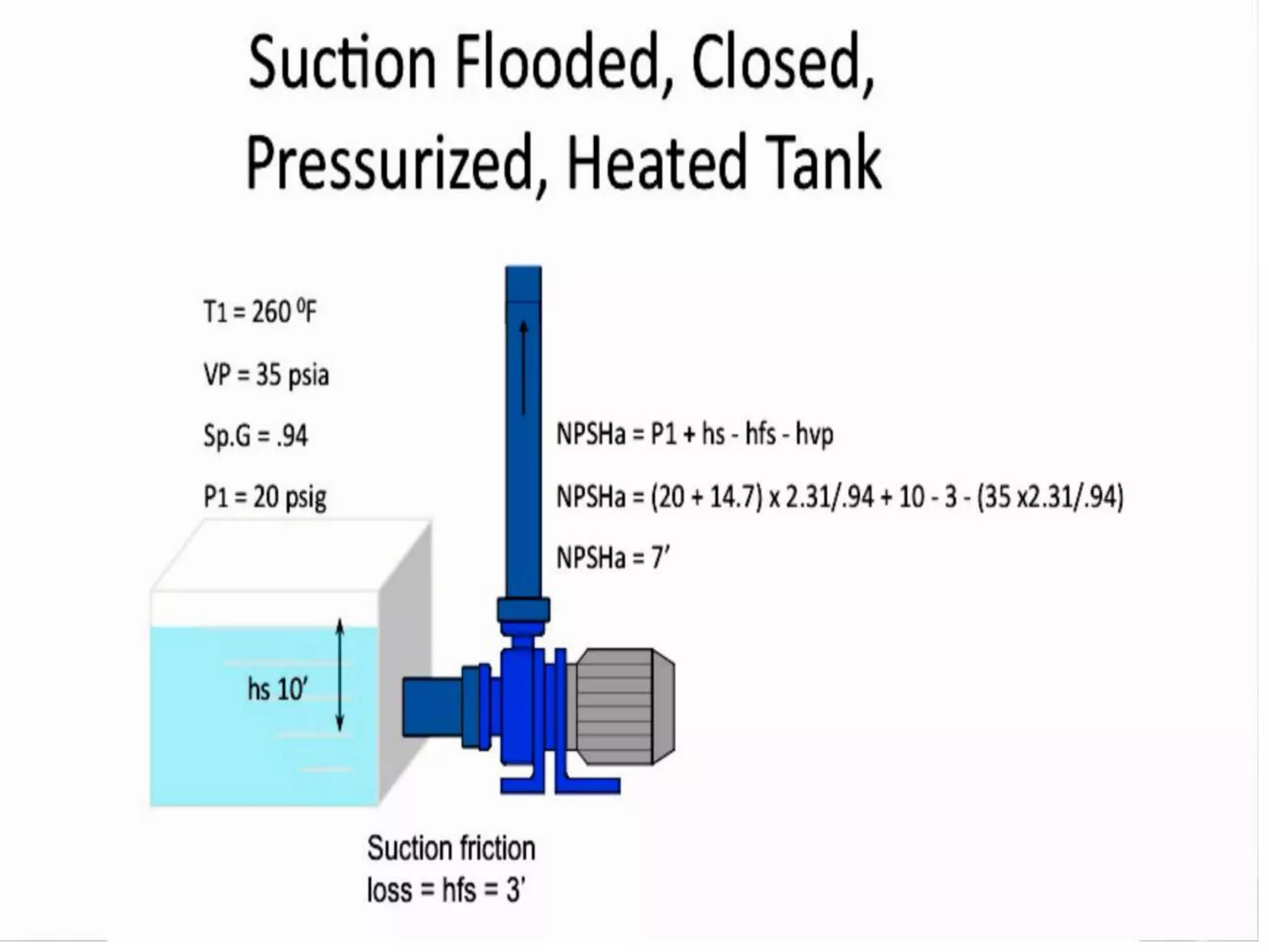
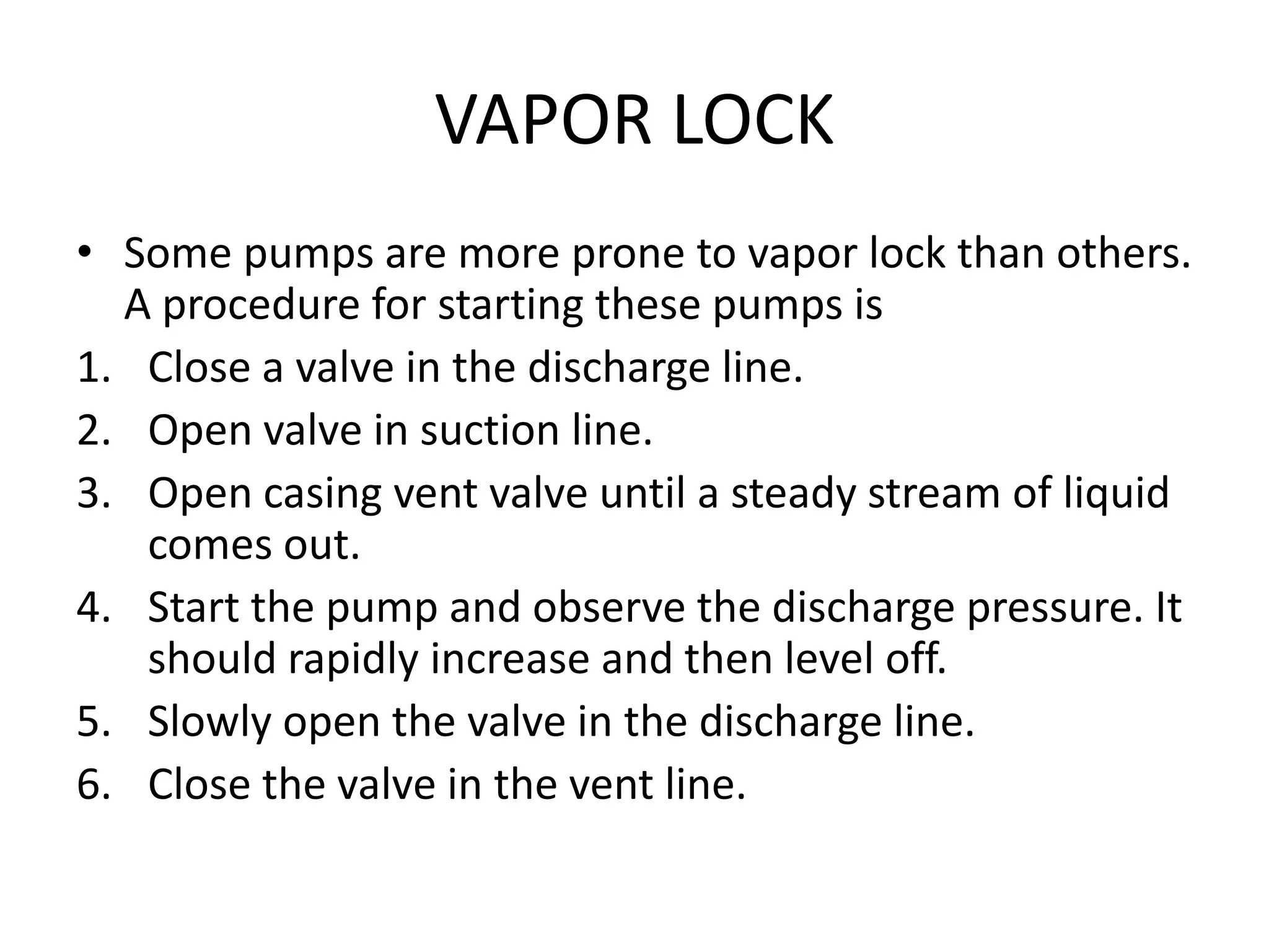
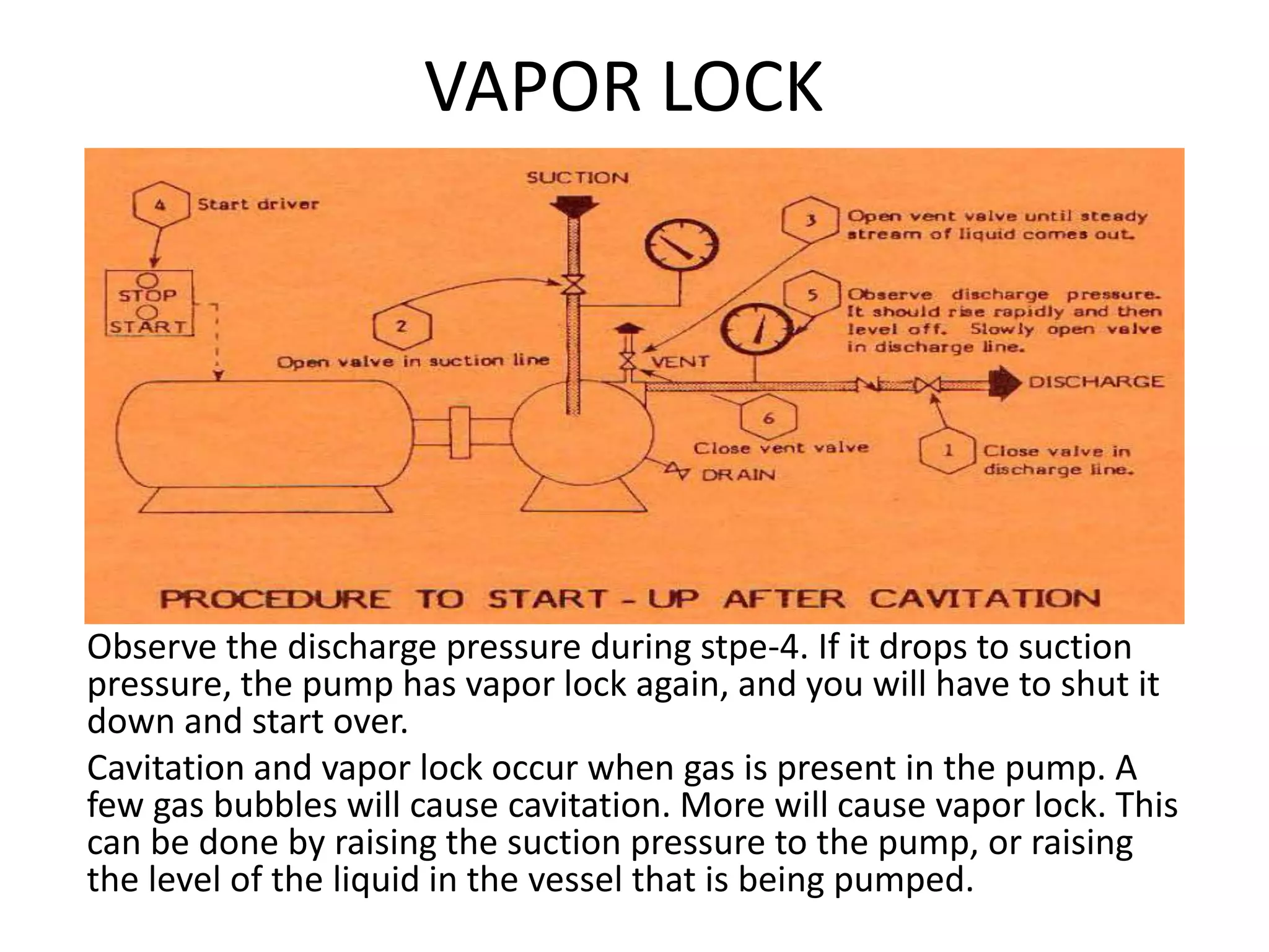


The document provides an overview of fluid mechanics and pumping systems relevant to chemical engineering, focusing on various components and principles of pumps, particularly centrifugal pumps. It describes the functions of key parts like impellers, shafts, and seals, and explains concepts such as head pressure, static head, and friction head, along with issues like cavitation and vapor lock. Lastly, it outlines the methods to handle vapor lock conditions in pumps to ensure effective operation.


![2938 [autosaved]](https://cdn.slidesharecdn.com/ss_thumbnails/2938autosaved-141224115226-conversion-gate02-thumbnail.jpg?width=640&height=640&fit=bounds)


![SHS_Core_CAE_Q3_LE1 FOR THIRD [FINAL].pdf](https://cdn.slidesharecdn.com/ss_thumbnails/shscorecaeq3le1final-251116055110-e3081055-thumbnail.jpg?width=640&height=640&fit=bounds)


