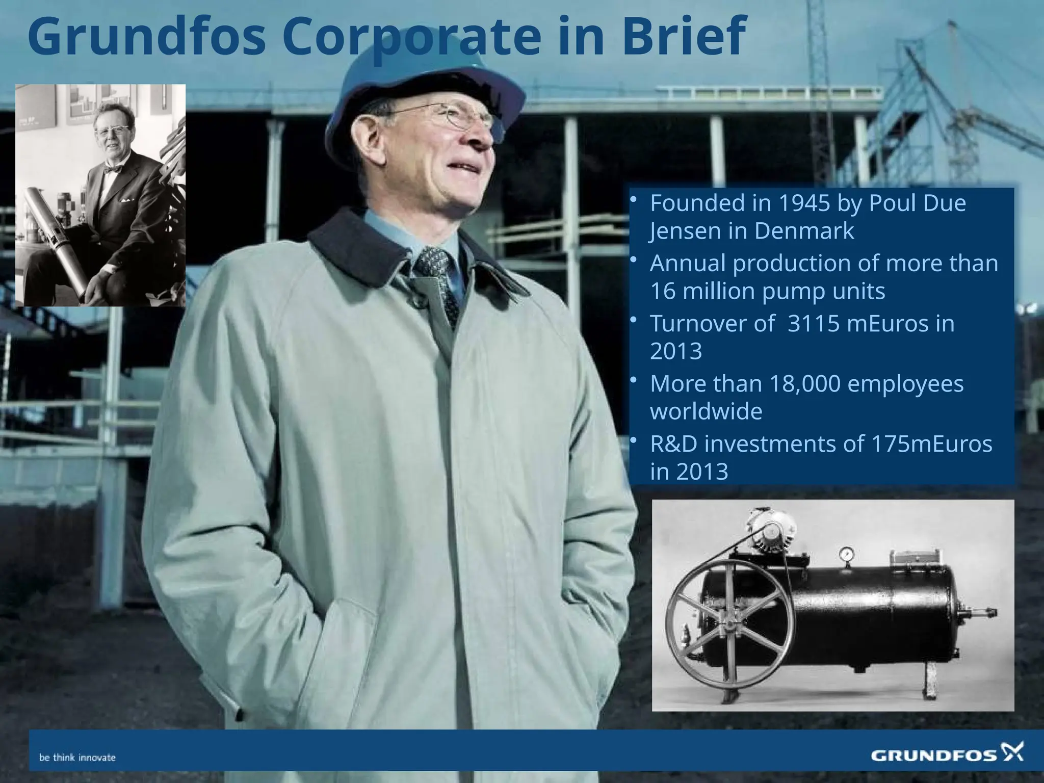
Grundfos Corporate inBrief
• Founded in 1945 by Poul Due
Jensen in Denmark
• Annual production of more than
16 million pump units
• Turnover of 3115 mEuros in
2013
• More than 18,000 employees
worldwide
• R&D investments of 175mEuros
in 2013
3.
Grundfos Production GloballyHungary
France
TaiwanUnited Kingdom
Germany
Fresno, California USA
Denmark
Mexico
Russia
Finland
China
220,000 sq m 20,000 sq m
61,000 sq m
40,000 sq m 9,000 sq m
20,000 sq m
10,000 sq m
15,000 sq m
10,000 sq m
18,000 sq m
41,000 sq m
Serbia
26,000 sq
m
Indianapolis, USA Brookshire, Texas
USA
Singapore
Wuxi, China
Yeomans, Illinois USA
6,000 sq m
44,000 sq m 2,000 sq m
10,000 sq m
7,000 sq m
4.
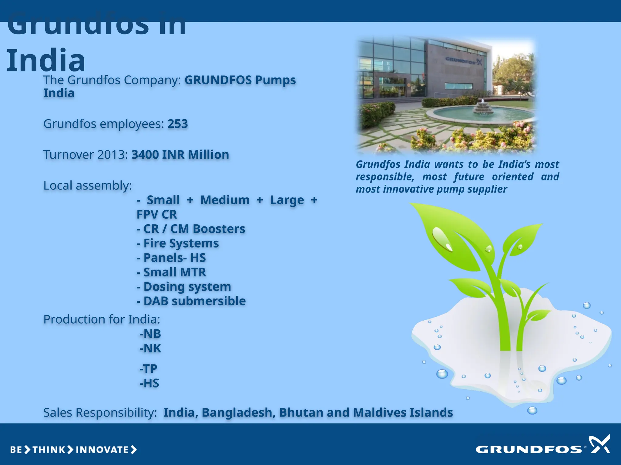
The Grundfos Company:GRUNDFOS Pumps
India
Grundfos employees: 253
Turnover 2013: 3400 INR Million
Sales Responsibility: India, Bangladesh, Bhutan and Maldives Islands
Grundfos India wants to be India’s most
responsible, most future oriented and
most innovative pump supplier
Production for India:
-NB
-NK
-TP
-HS
Local assembly:
- Small + Medium + Large +
FPV CR
- CR / CM Boosters
- Fire Systems
- Panels- HS
- Small MTR
- Dosing system
- DAB submersible
Grundfos in
India
5.
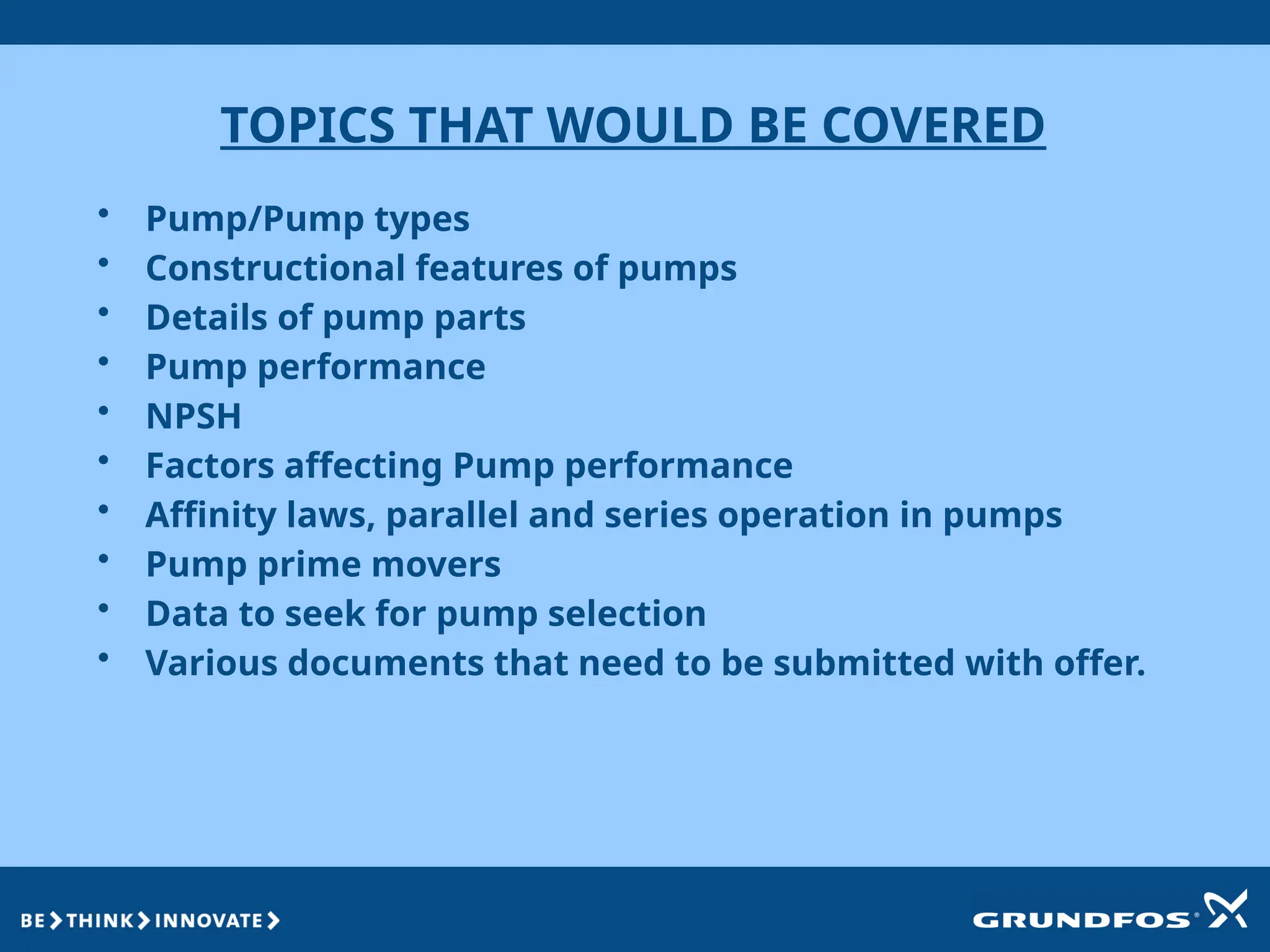
TOPICS THAT WOULDBE COVERED
• Pump/Pump types
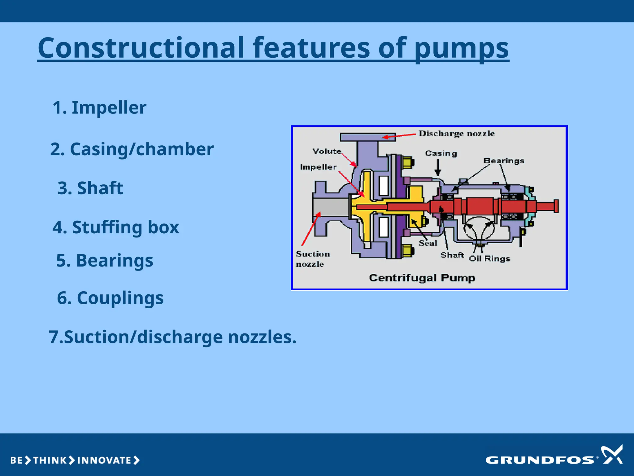
• Constructional features of pumps
• Details of pump parts
• Pump performance
• NPSH
• Factors affecting Pump performance
• Affinity laws, parallel and series operation in pumps
• Pump prime movers
• Data to seek for pump selection
• Various documents that need to be submitted with offer.
6.
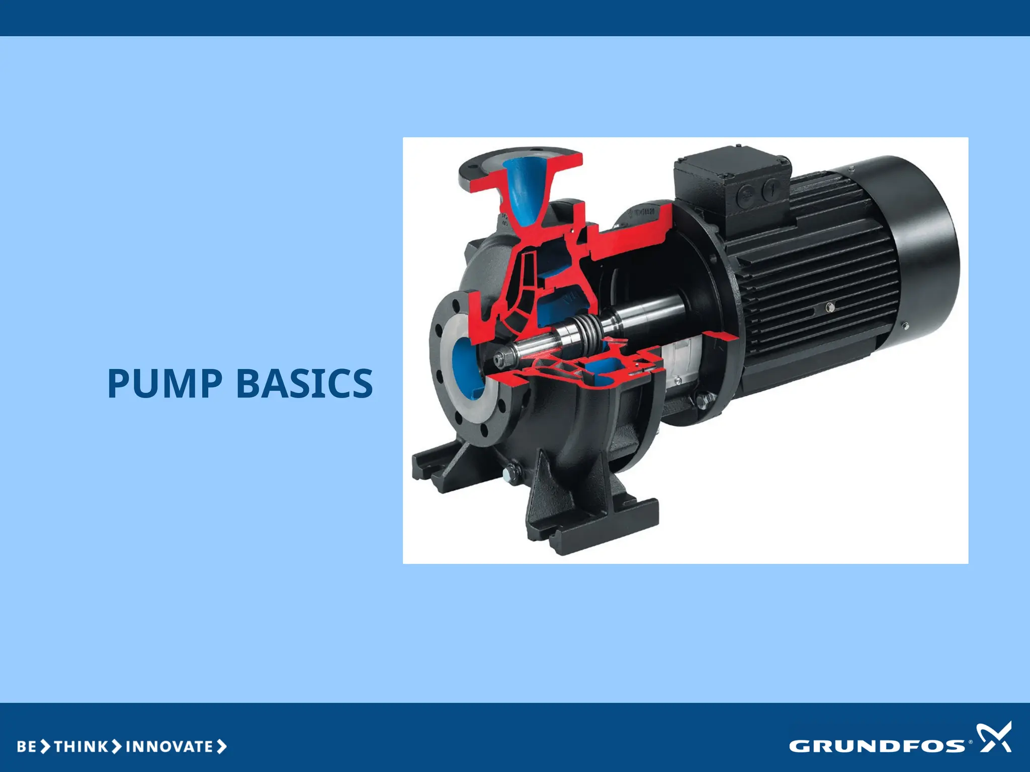
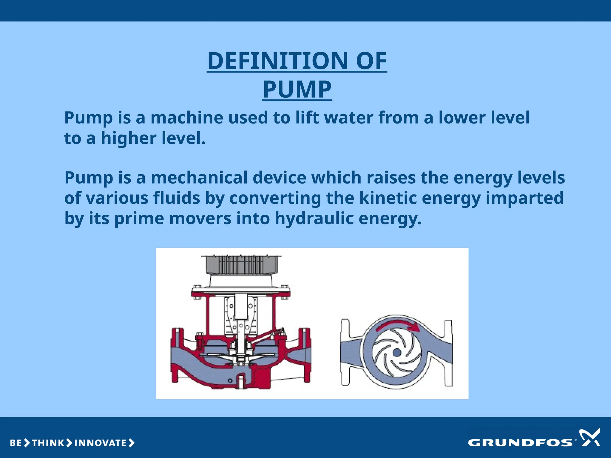
DEFINITION OF
PUMP
Pump isa mechanical device which raises the energy levels
of various fluids by converting the kinetic energy imparted
by its prime movers into hydraulic energy.
Pump is a machine used to lift water from a lower level
to a higher level.
7.
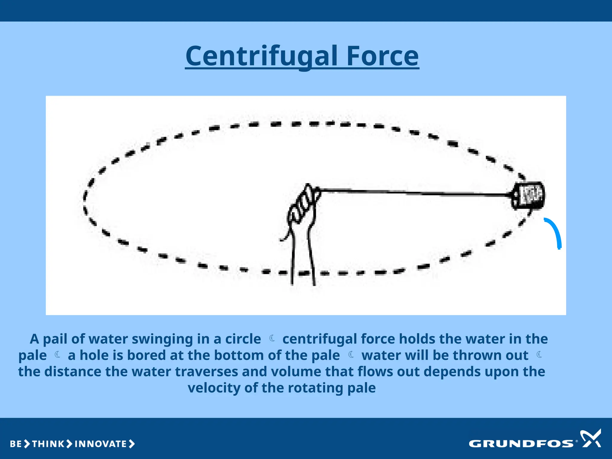
Centrifugal Force
A pailof water swinging in a circle centrifugal force holds the water in the
pale a hole is bored at the bottom of the pale water will be thrown out
the distance the water traverses and volume that flows out depends upon the
velocity of the rotating pale
8.
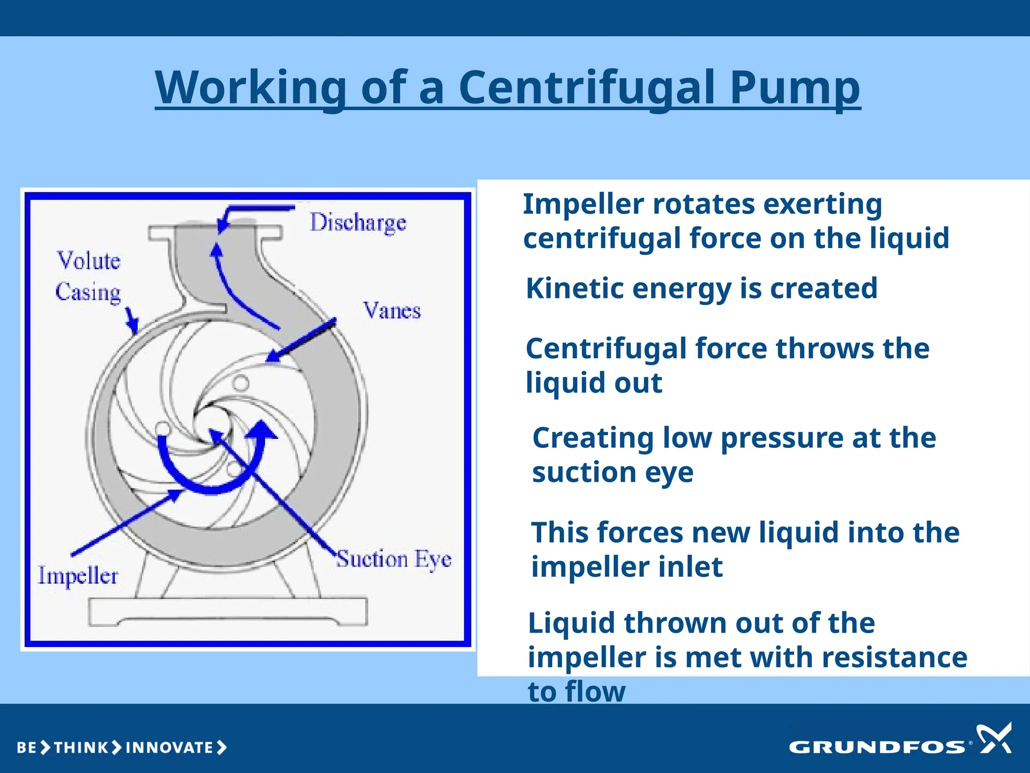
Working of aCentrifugal Pump
Impeller rotates exerting
centrifugal force on the liquid
Kinetic energy is created
Centrifugal force throws the
liquid out
Creating low pressure at the
suction eye
This forces new liquid into the
impeller inlet
Liquid thrown out of the
impeller is met with resistance
to flow
9.
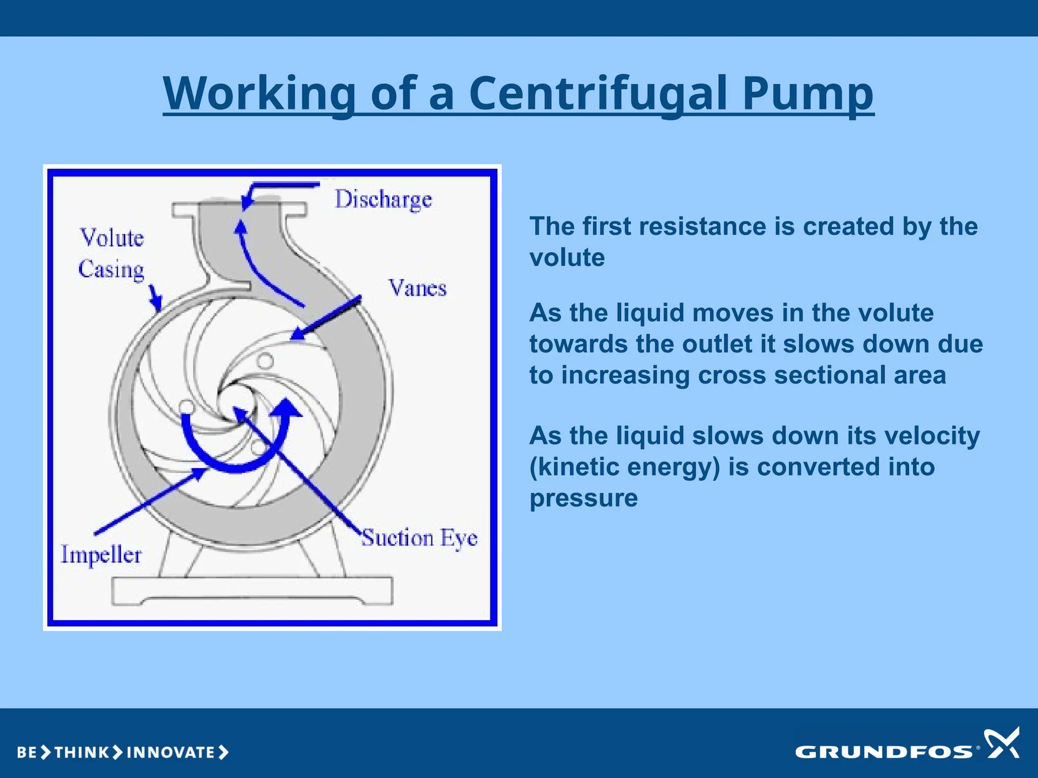
Working of aCentrifugal Pump
The first resistance is created by the
volute
As the liquid moves in the volute
towards the outlet it slows down due
to increasing cross sectional area
As the liquid slows down its velocity
(kinetic energy) is converted into
pressure
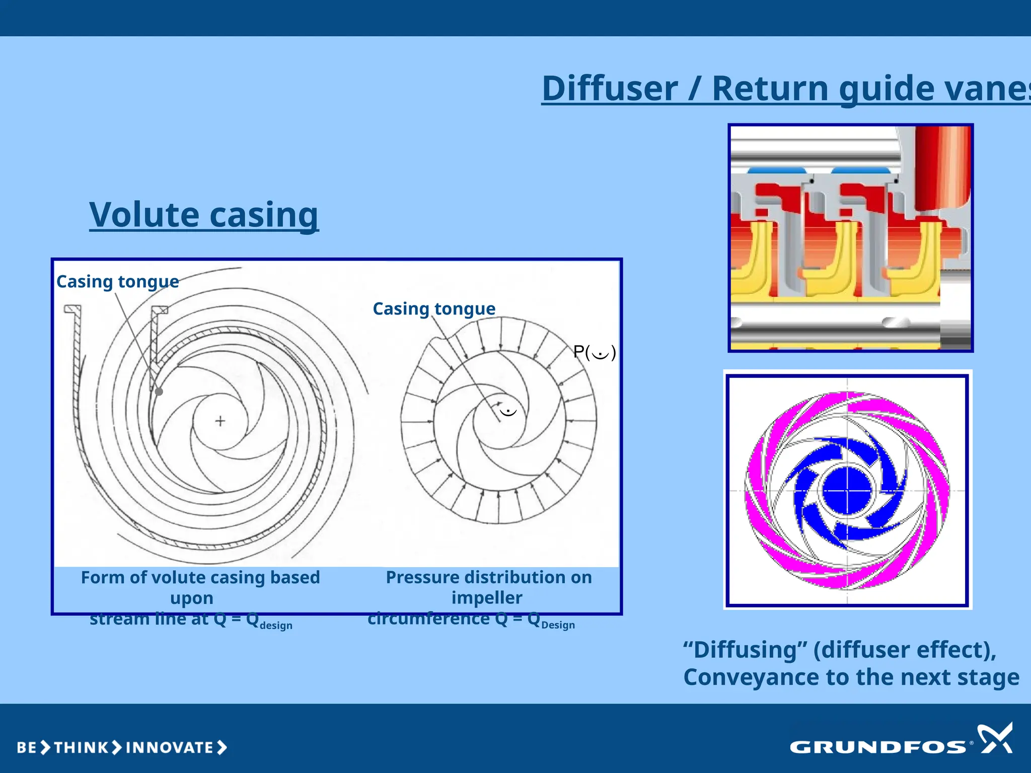
Volute casing
Pressure distributionon
impeller
circumference Q = QDesign
Diffuser / Return guide vanes
“Diffusing” (diffuser effect),
Conveyance to the next stage
Casing tongue
Casing tongue
P()
Form of volute casing based
upon
stream line at Q = Qdesign
12.
Shaft
Shaft is acomponent that carries all the rotating parts and also provides
power to the impeller.
The shaft has to withstand the rotating torque, axial and radial thrust.
Shaft material is selected considering the following:
1. Critical speed.
2. Endurance limit.
3. Corrosion resistance.
13.
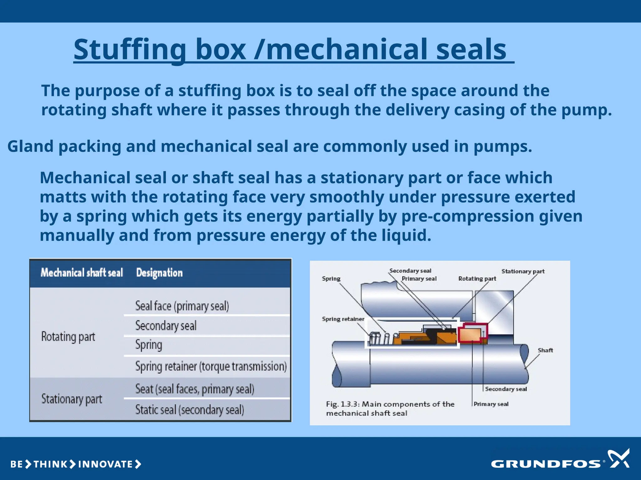
Stuffing box /mechanicalseals
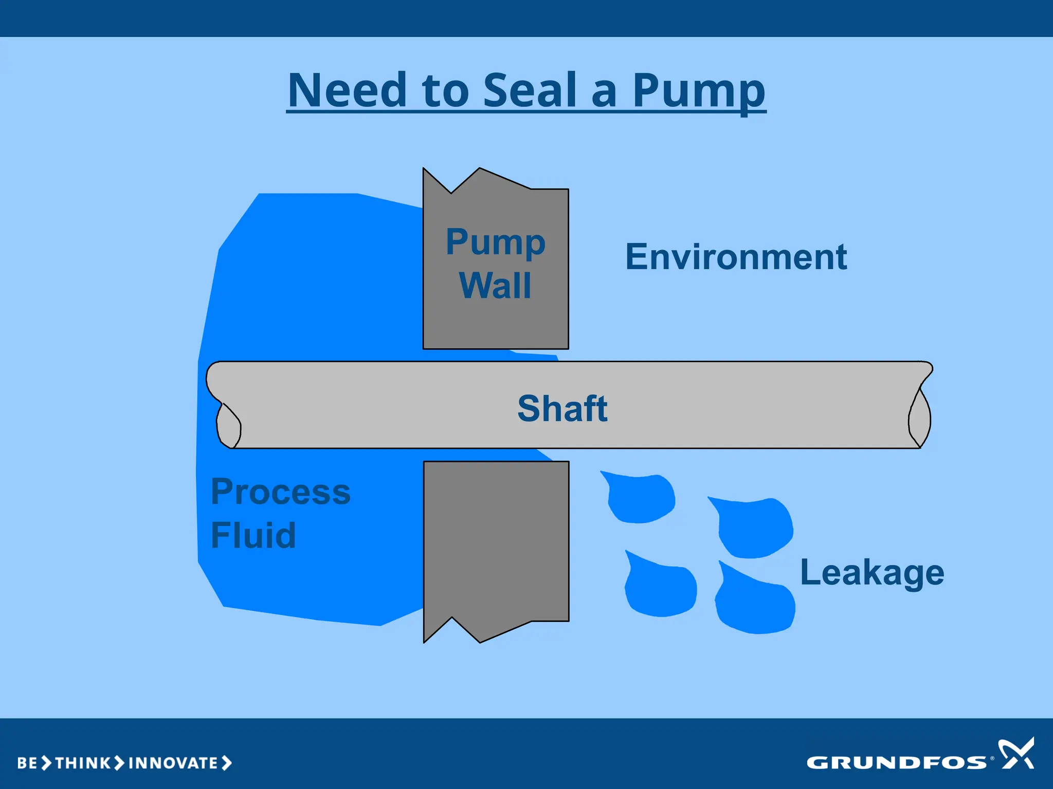
The purpose of a stuffing box is to seal off the space around the
rotating shaft where it passes through the delivery casing of the pump.
Gland packing and mechanical seal are commonly used in pumps.
Mechanical seal or shaft seal has a stationary part or face which
matts with the rotating face very smoothly under pressure exerted
by a spring which gets its energy partially by pre-compression given
manually and from pressure energy of the liquid.
14.
Need to Seala Pump
Shaft
Process
Fluid
Leakage
Environment
Pump
Wall
15.
Mechanical seal typesused in Grundfos
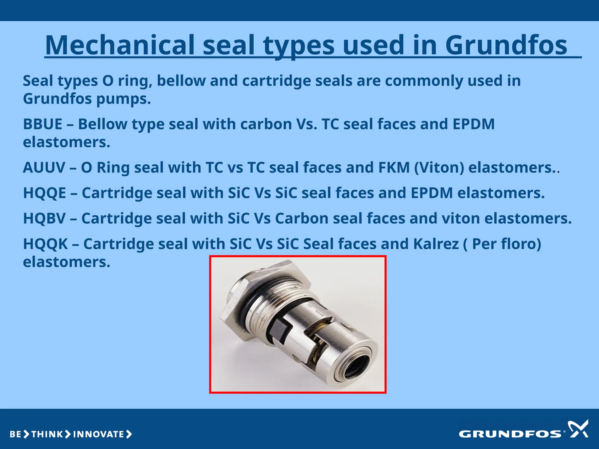
Seal types O ring, bellow and cartridge seals are commonly used in
Grundfos pumps.
BBUE – Bellow type seal with carbon Vs. TC seal faces and EPDM
elastomers.
AUUV – O Ring seal with TC vs TC seal faces and FKM (Viton) elastomers..
HQQE – Cartridge seal with SiC Vs SiC seal faces and EPDM elastomers.
HQBV – Cartridge seal with SiC Vs Carbon seal faces and viton elastomers.
HQQK – Cartridge seal with SiC Vs SiC Seal faces and Kalrez ( Per floro)
elastomers.
16.
Bearings
Bearings are themediums which keep the shaft or rotor in correct
alignment with its stationary parts under the action of axial and
radial thrusts.
Bearings which are designed to take radial thrust only are called
line bearings and those designed for axial thrust are called thrust
bearings.
Types of bearings
1. Bush bearings
2. Antifriction bearings
WE USE ANTIFRICTIONAL BEARINGS IN OUR NB/NK PUMPS. IN THE
CR ,THESE BEARING COME IN THE MOTOR
ANTIFRICTIONAL BEARINGS – BALL OR ROLLER TYPES.
17.
COUPLINGS
COUPLINGS ARE DEVICESUSED FOR CONNECTING PUMP WITH
THE PRIME MOVER. ITS MECHANICAL EQUIVALENT OF A FUSE
A COUPLING THAT CONNECTS TWO SHAFTS SOLIDLY FOR POWER
TRANSMISSION IS A RIGID COUPLING. EX: SLEEVE AND CLAMP
COUPLINGS
COUPLINGS ARE OF 2 TYPES
1. RIGID
2. FLEXIBLE
A FLEXIBLE COUPLING ALLOWS FOR EASY ASSEMBLY AND DISMANTLING ,
WITHOUT DISTURBING THE SHAFTS . THEY ARE USED FOR POWER
TRANSMISSION BY MEANS OF MECHANICAL JOINT WITHOUT SLIP IN
MOTION.
Ex: PIN AND BUSH TYPE, LOVEJOY , DISC TYPE COUPLINGS
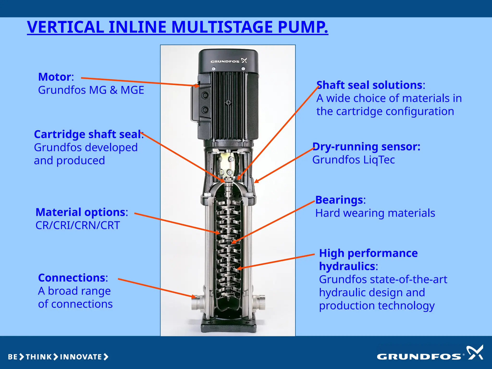
VERTICAL INLINE MULTISTAGEPUMP.
Motor:
Grundfos MG & MGE
Cartridge shaft seal:
Grundfos developed
and produced
Material options:
CR/CRI/CRN/CRT
Connections:
A broad range
of connections
Bearings:
Hard wearing materials
Dry-running sensor:
Grundfos LiqTec
High performance
hydraulics:
Grundfos state-of-the-art
hydraulic design and
production technology
Shaft seal solutions:
A wide choice of materials in
the cartridge configuration
22.
True or False.
•In centrifugal pump the pressure increases with increase in
rotational speed of impeller.
• Diffuser casing is used in single stage pumps.
• You can tighten the gland packing to avoid leakage at site.
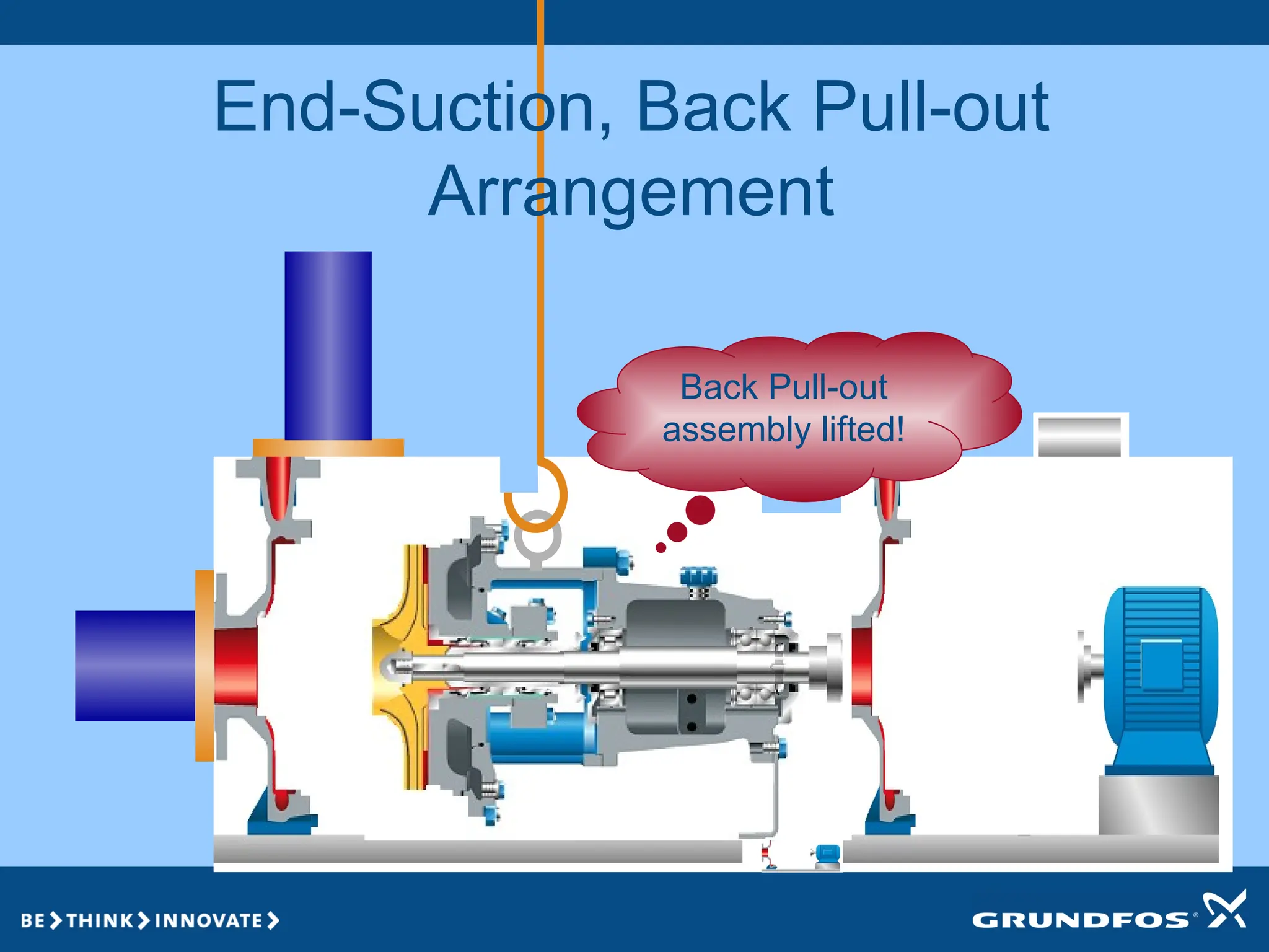
• Vertical Split Case, Back Pull Out & End Suction are same in
construction.
• Mechanical seals are always recommended for smooth &
clean operation of pumps.
• In back pull out type pump the pump maintenance can be
done without disturbing piping at site.
23.
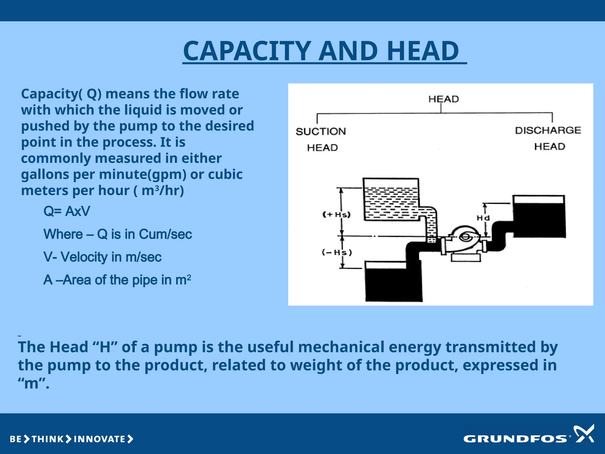
CAPACITY AND HEAD
Q=AxV
Where – Q is in Cum/sec
V- Velocity in m/sec
A –Area of the pipe in m2
Capacity( Q) means the flow rate
with which the liquid is moved or
pushed by the pump to the desired
point in the process. It is
commonly measured in either
gallons per minute(gpm) or cubic
meters per hour ( m3
/hr)
The Head “H” of a pump is the useful mechanical energy transmitted by
the pump to the product, related to weight of the product, expressed in
“m”.
24.
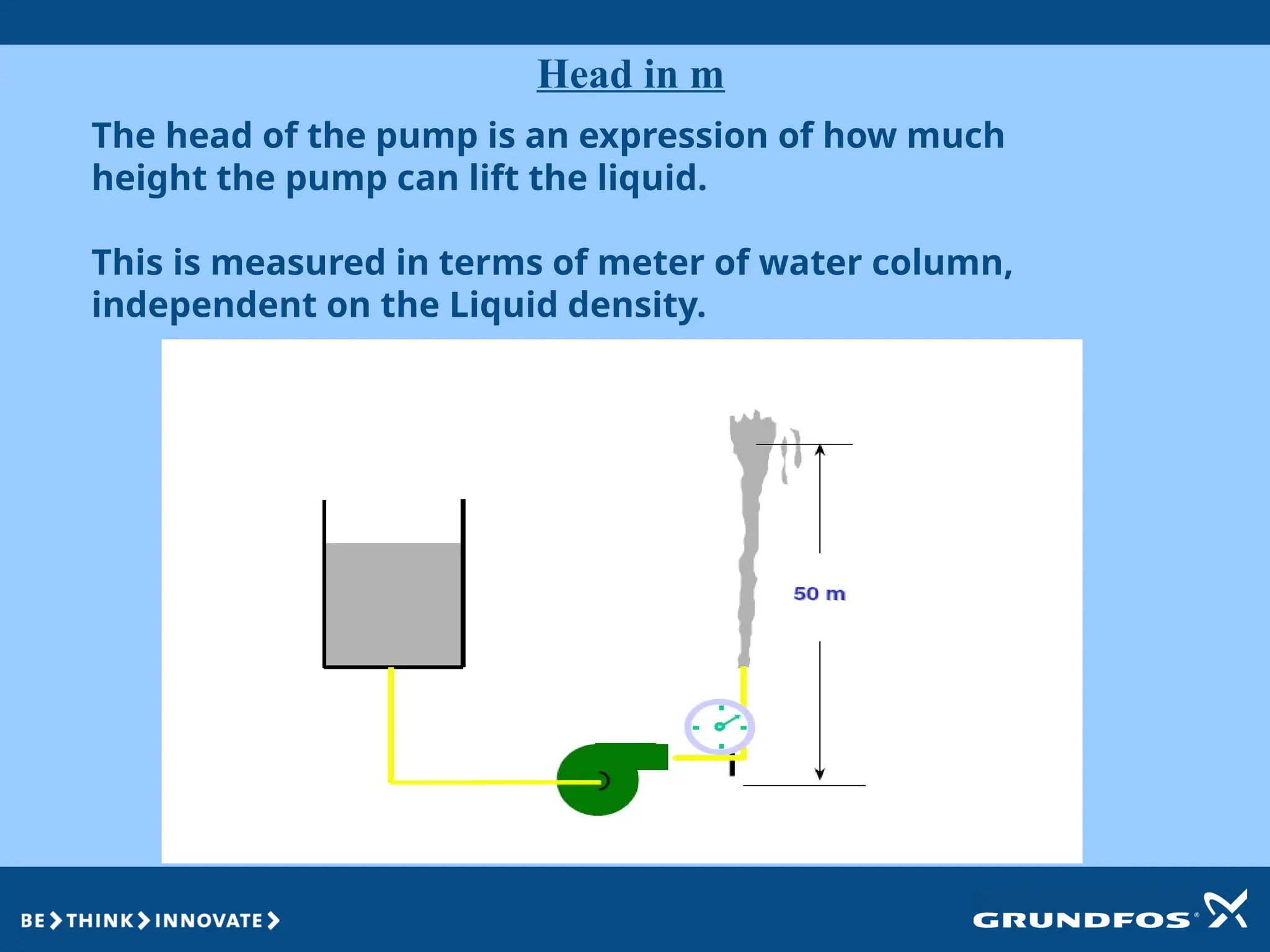
Head in m
Thehead of the pump is an expression of how much
height the pump can lift the liquid.
This is measured in terms of meter of water column,
independent on the Liquid density.
25.
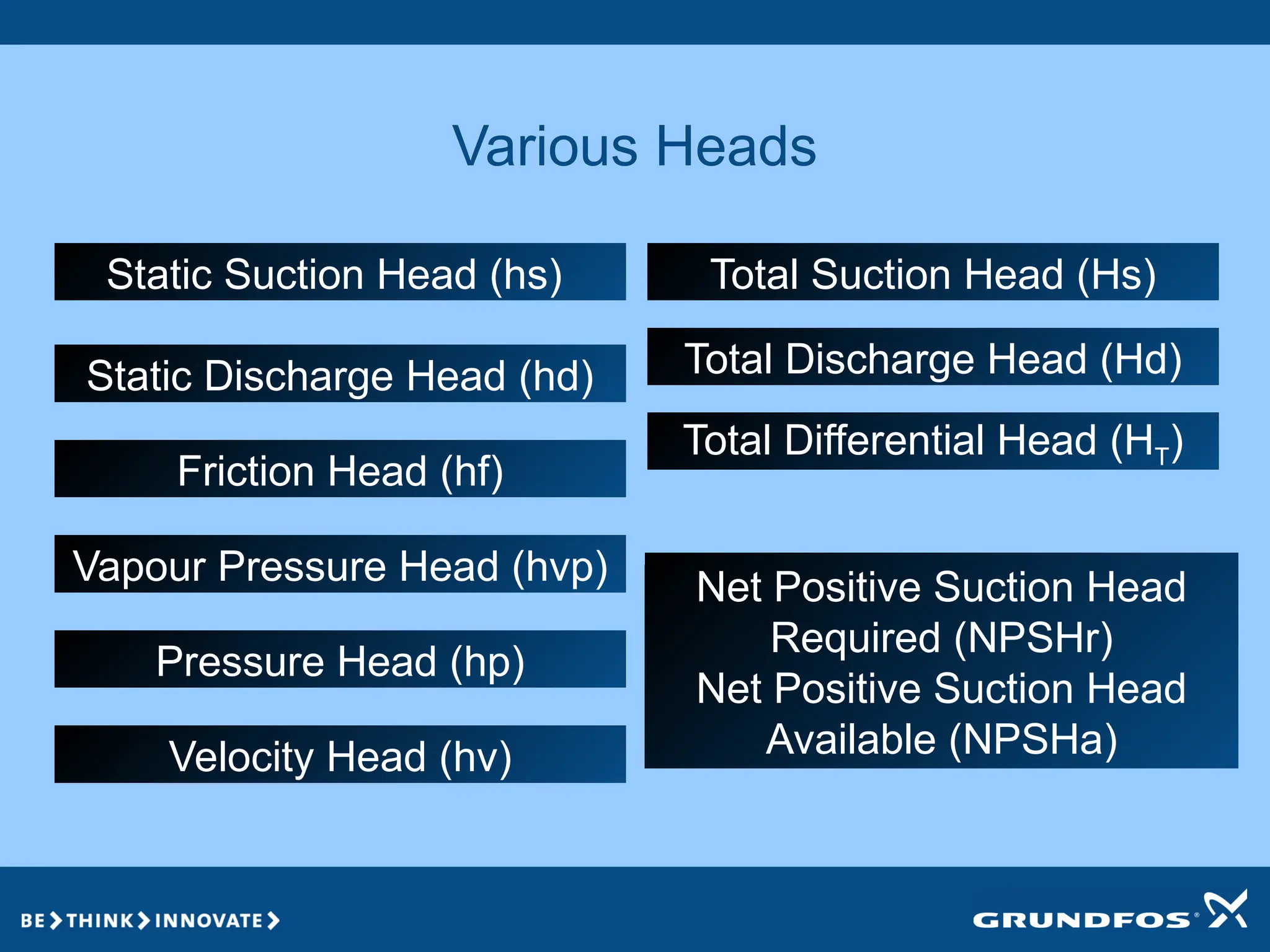
Various Heads
Friction Head(hf)
Total Differential Head (HT)
Velocity Head (hv)
Static Discharge Head (hd) Total Discharge Head (Hd)
Static Suction Head (hs) Total Suction Head (Hs)
Pressure Head (hp)
Vapour Pressure Head (hvp) Net Positive Suction Head
Required (NPSHr)
Net Positive Suction Head
Available (NPSHa)
26.
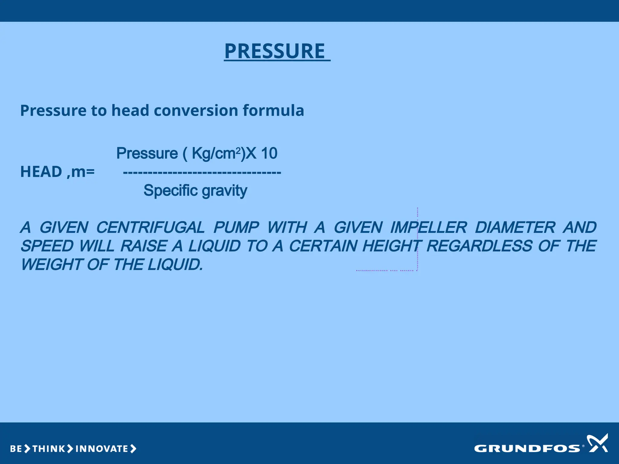
PRESSURE
Pressure to headconversion formula
Pressure ( Kg/cm2
)X 10
HEAD ,m= --------------------------------
Specific gravity
A GIVEN CENTRIFUGAL PUMP WITH A GIVEN IMPELLER DIAMETER AND
SPEED WILL RAISE A LIQUID TO A CERTAIN HEIGHT REGARDLESS OF THE
WEIGHT OF THE LIQUID.
27.
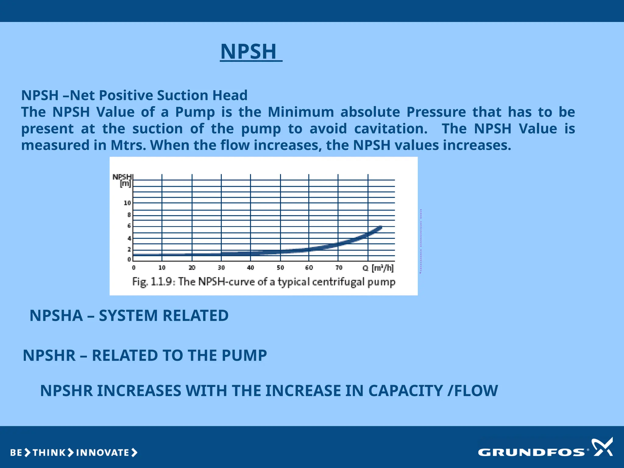
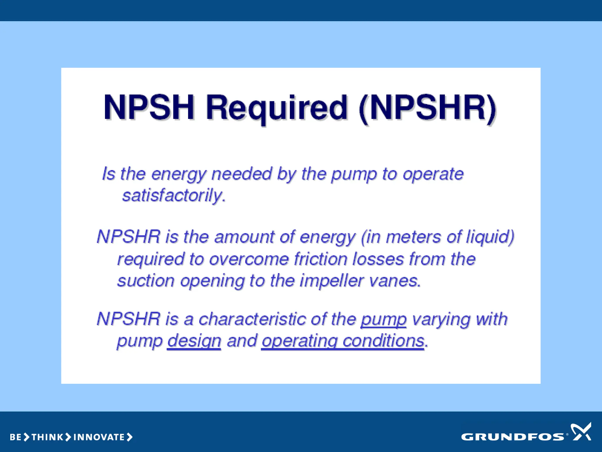
NPSH
NPSH –Net PositiveSuction Head
The NPSH Value of a Pump is the Minimum absolute Pressure that has to be
present at the suction of the pump to avoid cavitation. The NPSH Value is
measured in Mtrs. When the flow increases, the NPSH values increases.
NPSHA – SYSTEM RELATED
NPSHR – RELATED TO THE PUMP
NPSHR INCREASES WITH THE INCREASE IN CAPACITY /FLOW
28.
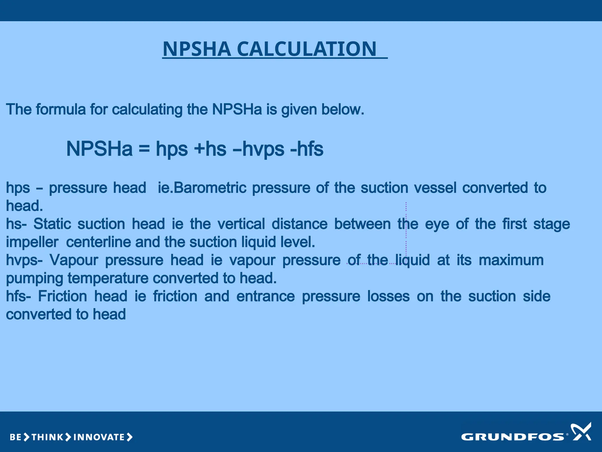
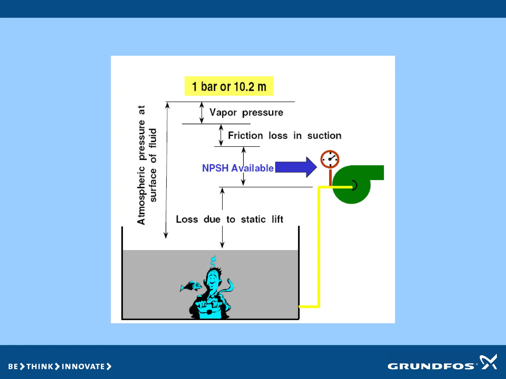
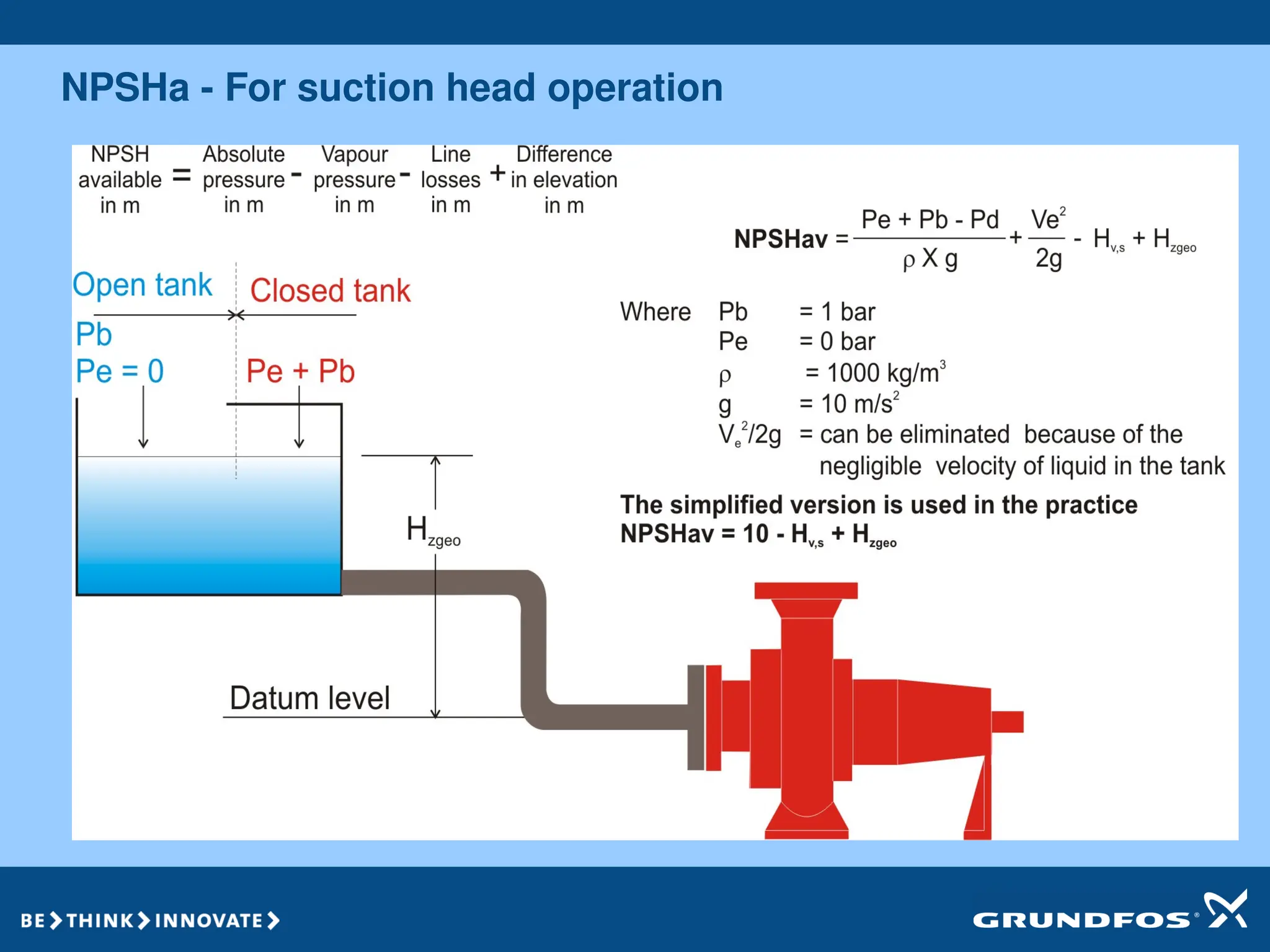
NPSHA CALCULATION
The formulafor calculating the NPSHa is given below.
NPSHa = hps +hs –hvps -hfs
hps – pressure head ie.Barometric pressure of the suction vessel converted to
head.
hs- Static suction head ie the vertical distance between the eye of the first stage
impeller centerline and the suction liquid level.
hvps- Vapour pressure head ie vapour pressure of the liquid at its maximum
pumping temperature converted to head.
hfs- Friction head ie friction and entrance pressure losses on the suction side
converted to head
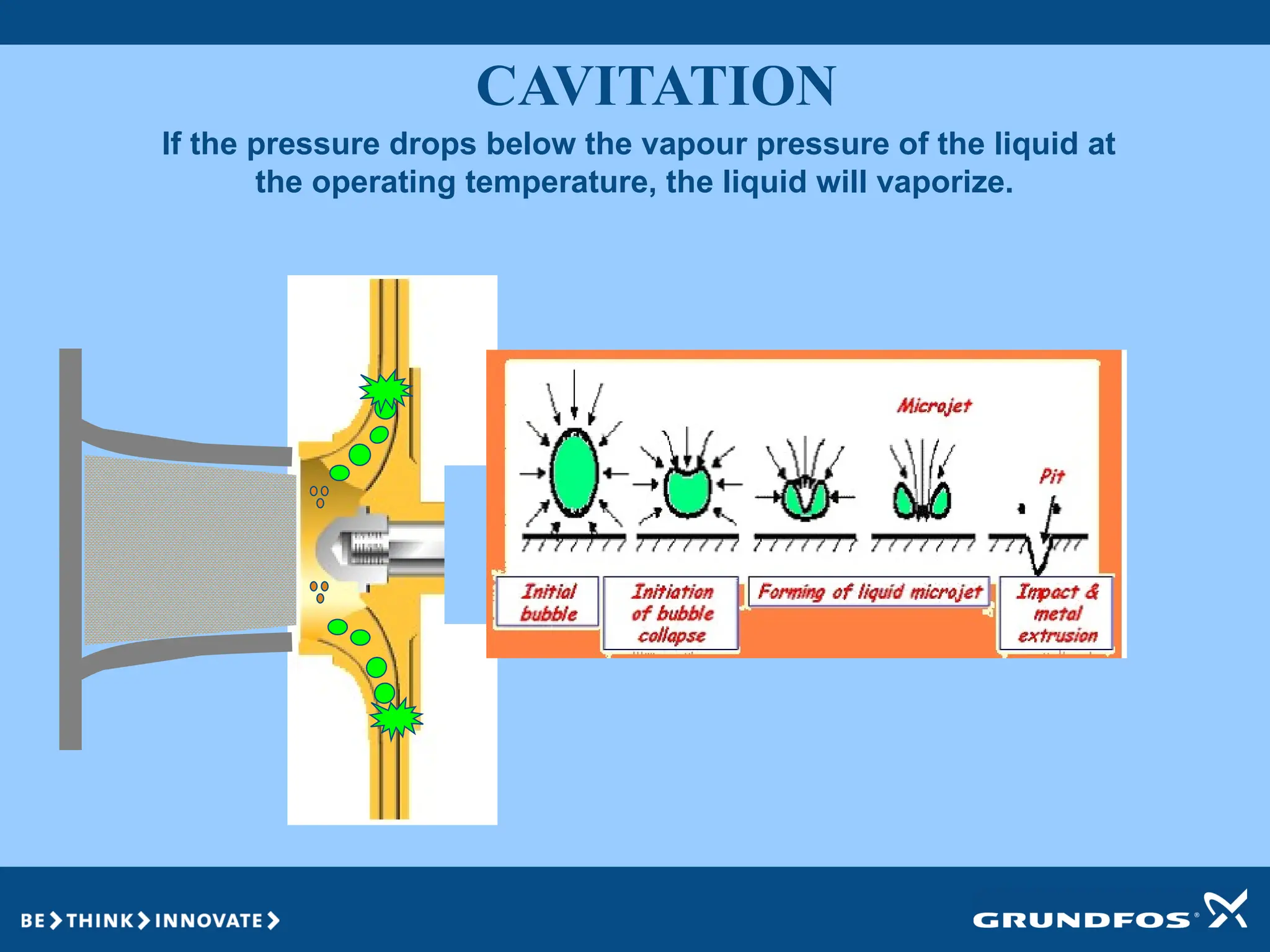
If the pressuredrops below the vapour pressure of the liquid at
the operating temperature, the liquid will vaporize.
CAVITATION
34.
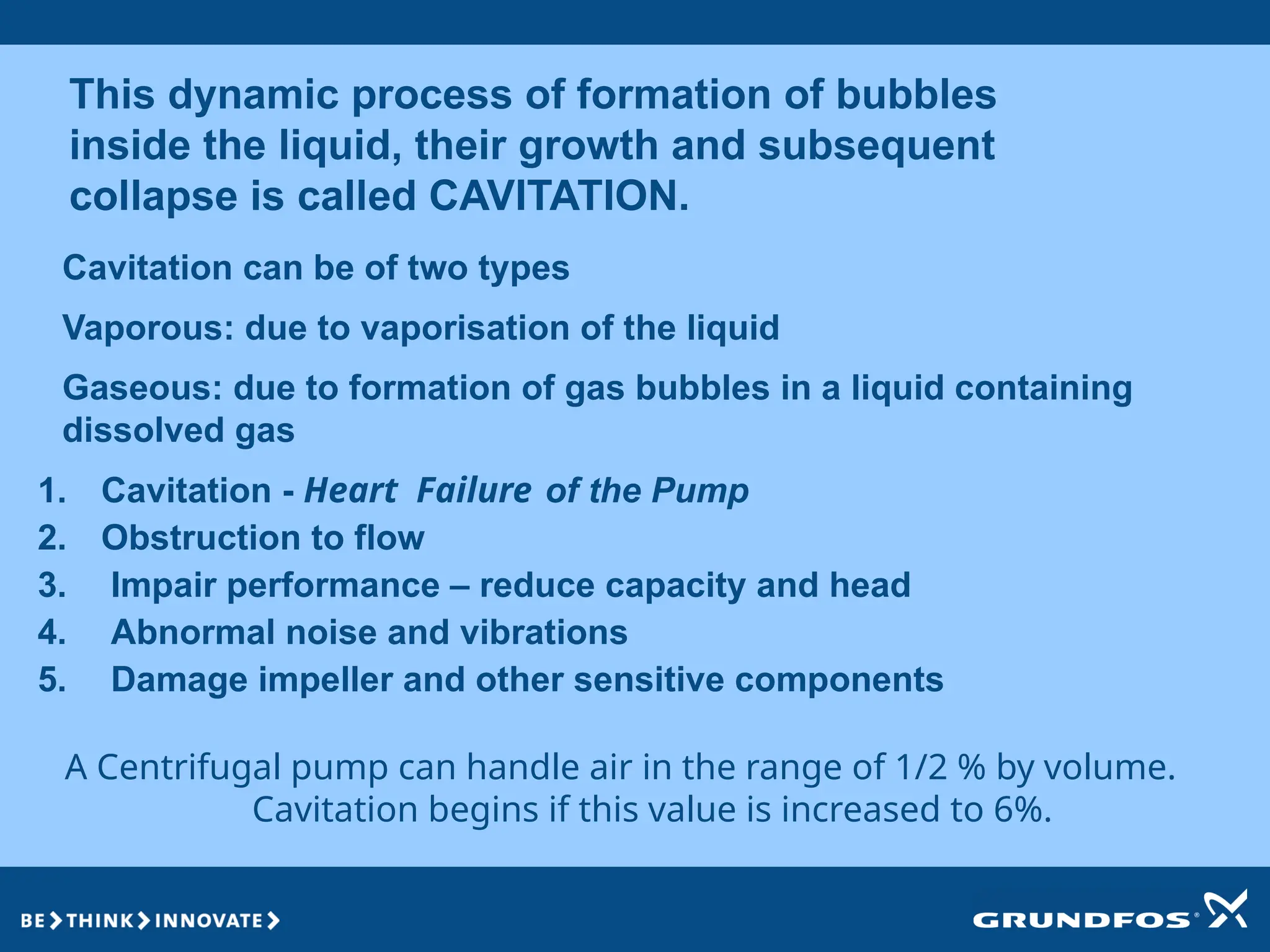
This dynamic processof formation of bubbles
inside the liquid, their growth and subsequent
collapse is called CAVITATION.
Cavitation can be of two types
Vaporous: due to vaporisation of the liquid
Gaseous: due to formation of gas bubbles in a liquid containing
dissolved gas
A Centrifugal pump can handle air in the range of 1/2 % by volume.
Cavitation begins if this value is increased to 6%.
1. Cavitation - Heart Failure of the Pump
2. Obstruction to flow
3. Impair performance – reduce capacity and head
4. Abnormal noise and vibrations
5. Damage impeller and other sensitive components
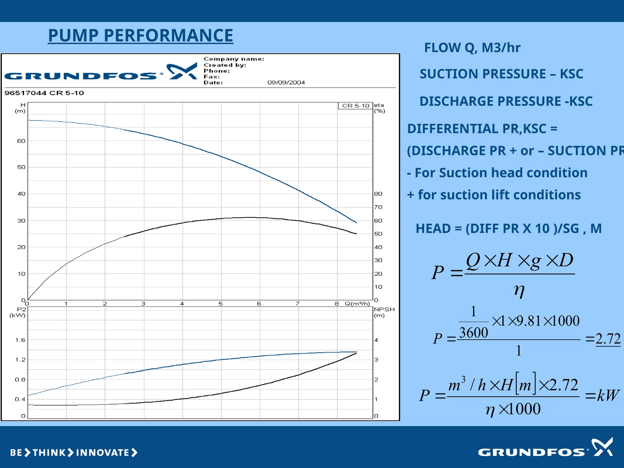
PUMP PERFORMANCE
FLOW Q,M3/hr
SUCTION PRESSURE – KSC
DISCHARGE PRESSURE -KSC
DIFFERENTIAL PR,KSC =
(DISCHARGE PR + or – SUCTION PR
- For Suction head condition
+ for suction lift conditions
HEAD = (DIFF PR X 10 )/SG , M
kW
m
H
h
m
P
1000
72
.
2
/
3
D
g
H
Q
P
72
.
2
1
1000
81
.
9
1
3600
1
P
38.
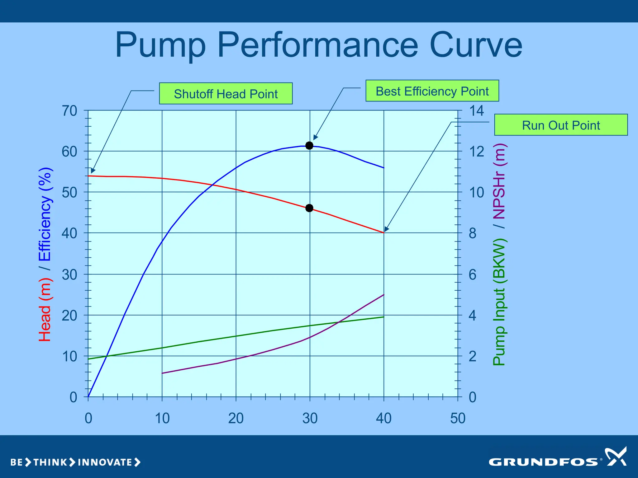
Pump Performance Curve
0
10
20
30
40
50
60
70
010 20 30 40 50
Capacity(m3/hr)
Head
(m)
/
Efficiency
(%)
0
2
4
6
8
10
12
14
Pump
Input
(BKW)
/
NPSHr
(m)
Best Efficiency Point
Shutoff Head Point
Run Out Point
39.
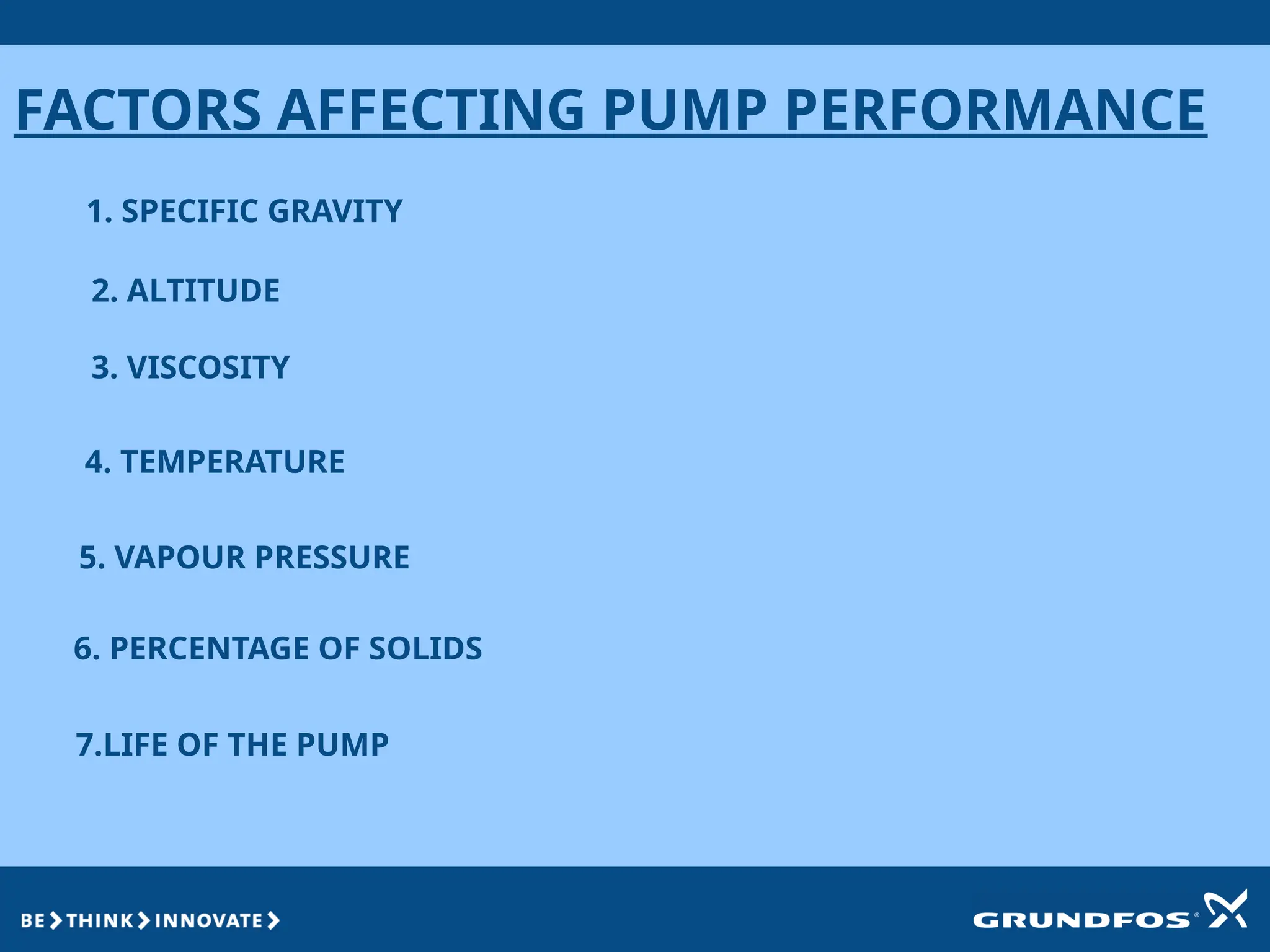
FACTORS AFFECTING PUMPPERFORMANCE
1. SPECIFIC GRAVITY
2. ALTITUDE
3. VISCOSITY
4. TEMPERATURE
5. VAPOUR PRESSURE
6. PERCENTAGE OF SOLIDS
7.LIFE OF THE PUMP
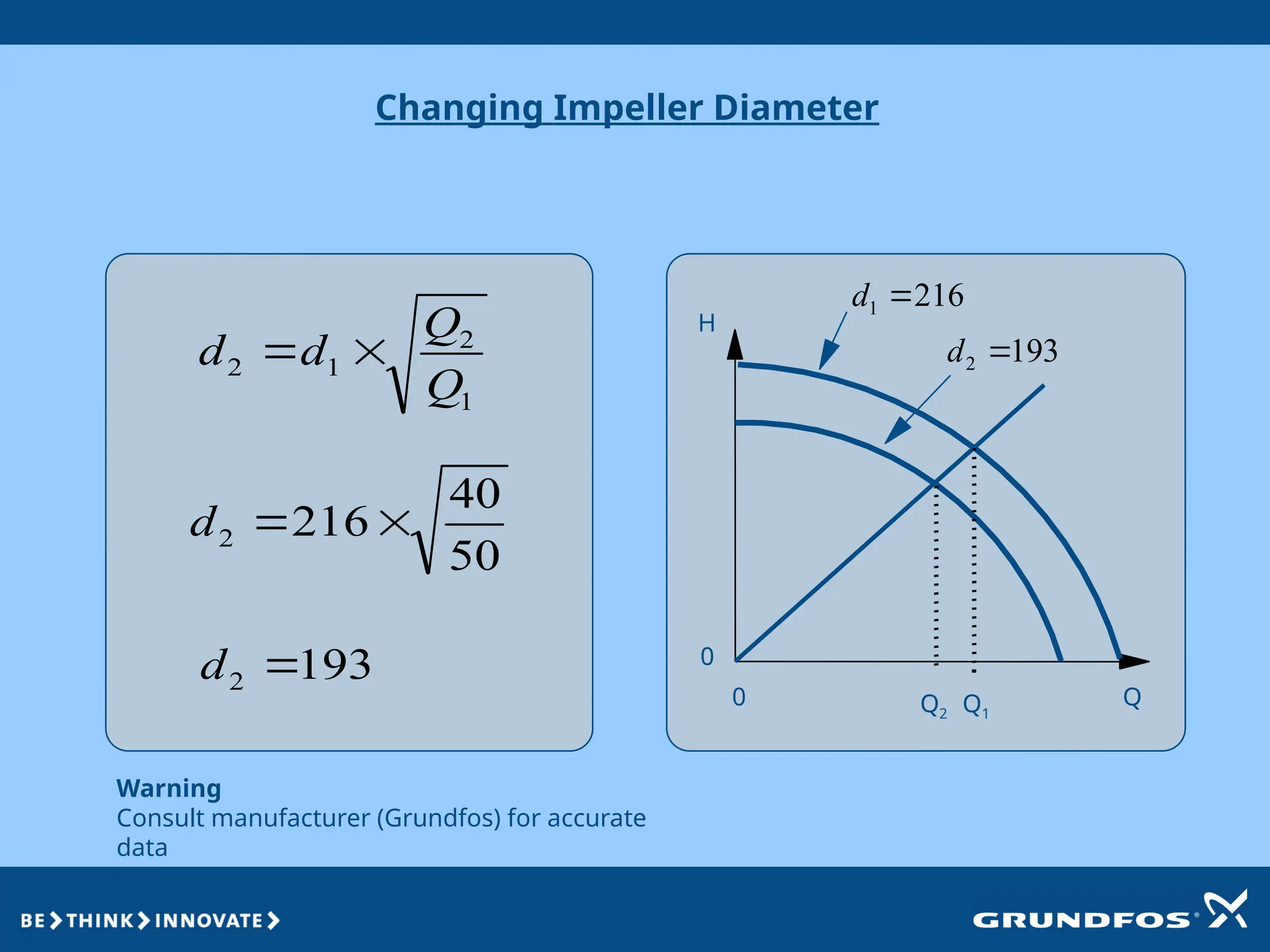
Warning
Consult manufacturer (Grundfos)for accurate
data
Q2
H
Q
0
0
Changing Impeller Diameter
1
2
1
2
Q
Q
d
d
50
40
216
2
d
193
2
d
Q1
216
1
d
193
2
d
43.
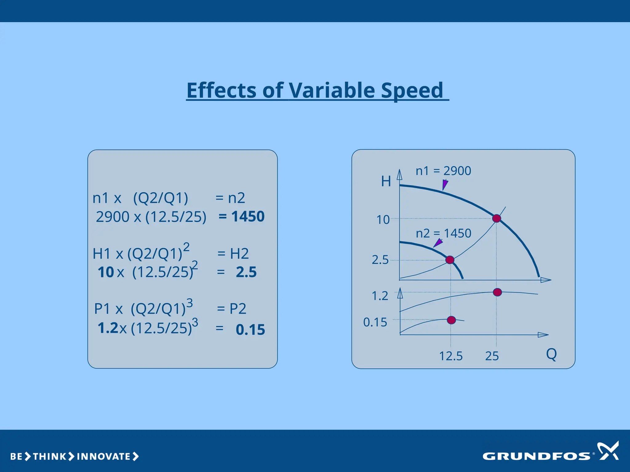
Effects of VariableSpeed
2
3
H
Q
n1 = 2900
n1 x (Q2/Q1) = n2
2900 x (12.5/25) = 1450
H1 x (Q2/Q1) = H2
10 x (12.5/25) = 2.5
P1 x (Q2/Q1) = P2
1.2x (12.5/25) = 0.15
2
3
12.5 25
10
2.5
1.2
0.15
n2 = 1450
44.
Parallel Operation ofSimilar Pumps
Theoretic:
Double flow [2 x Q]
Same head [1 x H]
H
Q
PRIME MOVERS OFA PUMP
PRIME MOVERS ARE POWER TRANSMISSION DEVICES TO IMPEL /PROPEL THE PUMP
TYPES OF PRIME MOVERS USED IN PUMP APPLICATIONS
1. ELECTRIC MOTORS – INDUCTION MOTORS
2. DIESEL ENGINES
3. STEAM /GAS OR HYDRAULIC TURBINES
4. STEAM ENGINES
47.
True or False.
•Pump capacity is inversely proportional to pump head.
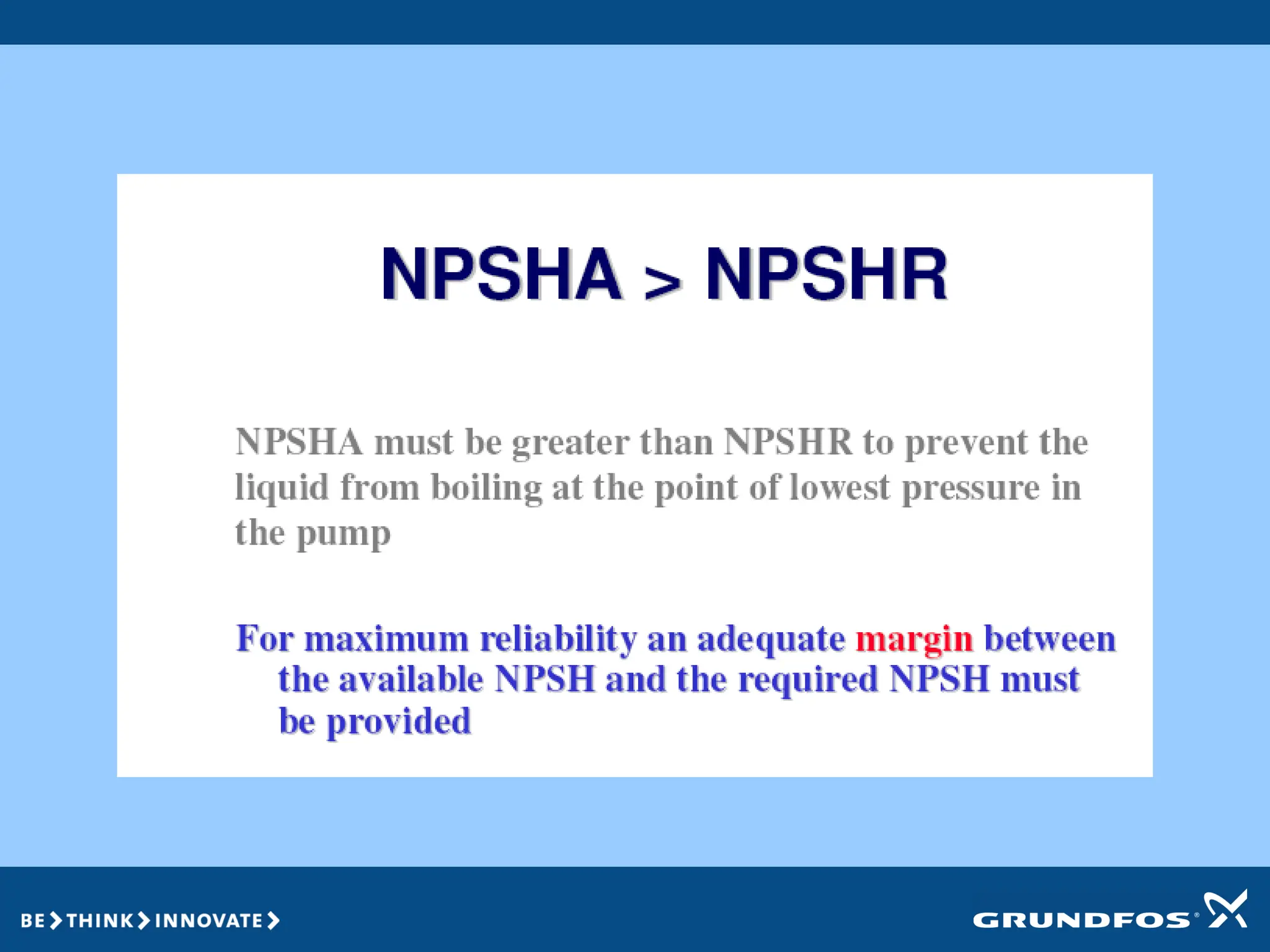
• If NPSHa is less than NPSHr then pump cavitates.
• Pump sucks the liquid & then sends it to discharge line.
• In series operation the capacity gets added up & in parallel
head gets added up.
• As per law of affinity the power changes to the cube of
speed.
• With the closing of valves the pressure also gets reduced.
48.
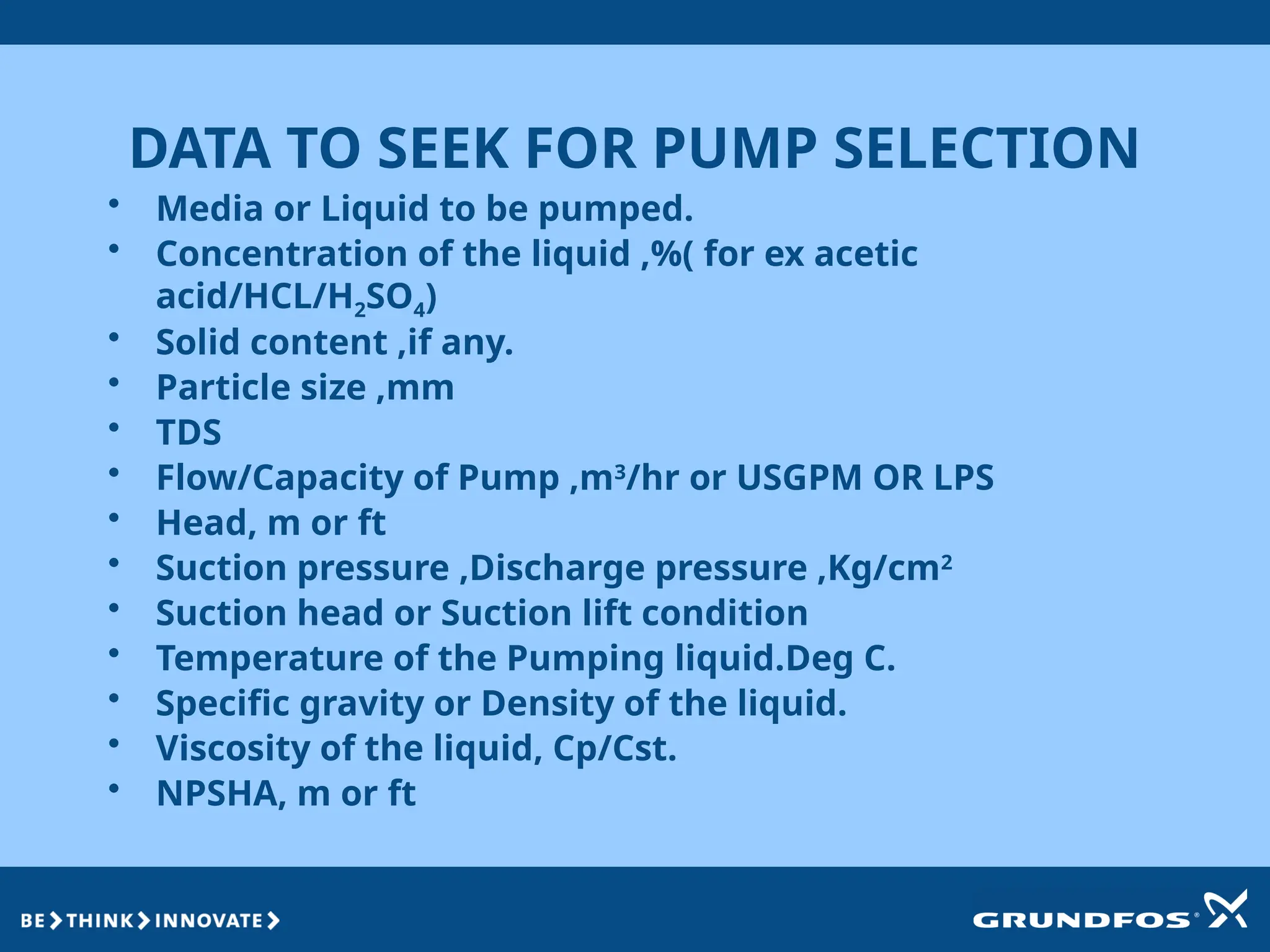
DATA TO SEEKFOR PUMP SELECTION
• Media or Liquid to be pumped.
• Concentration of the liquid ,%( for ex acetic
acid/HCL/H2SO4)
• Solid content ,if any.
• Particle size ,mm
• TDS
• Flow/Capacity of Pump ,m3
/hr or USGPM OR LPS
• Head, m or ft
• Suction pressure ,Discharge pressure ,Kg/cm2
• Suction head or Suction lift condition
• Temperature of the Pumping liquid.Deg C.
• Specific gravity or Density of the liquid.
• Viscosity of the liquid, Cp/Cst.
• NPSHA, m or ft
49.
DOCUMENTS TO BESUBMITTED ALONGWITH OFFER
1. DATA SHEET
2. PUMP PERFORMANCE CURVE
3. GA DRAWING

![Parallel Operation of Similar Pumps
Theoretic:
Double flow [2 x Q]
Same head [1 x H]
H
Q](https://image.slidesharecdn.com/presentationonpumpbasics-250918070233-a7f67067/75/Presentation-on-pump-basics-explains-the-basics-of-operation-of-pumps-44-2048.jpg)
![Theoretic:
Double head [2 x H]
Same flow [1 x Q]
Q
H
Series Operation of Pumps](https://image.slidesharecdn.com/presentationonpumpbasics-250918070233-a7f67067/75/Presentation-on-pump-basics-explains-the-basics-of-operation-of-pumps-45-2048.jpg)


![Parallel Operation of Similar Pumps
Theoretic:
Double flow [2 x Q]
Same head [1 x H]
H
Q](https://crownmelresort.com/image.slidesharecdn.com/presentationonpumpbasics-250918070233-a7f67067/75/Presentation-on-pump-basics-explains-the-basics-of-operation-of-pumps-44-2048.jpg)
![Theoretic:
Double head [2 x H]
Same flow [1 x Q]
Q
H
Series Operation of Pumps](https://crownmelresort.com/image.slidesharecdn.com/presentationonpumpbasics-250918070233-a7f67067/75/Presentation-on-pump-basics-explains-the-basics-of-operation-of-pumps-45-2048.jpg)


