VTU IOT LAB MANUAL (BCS701) Computer science and Engineering
1.
ALVA’S INSTITUTE OFENGINEERING & TECHNOLOGY
(A Unit of Alva’s Education Foundation, Moodabidri)
Autonomous Institute, Affiliated to VTU, Belagavi, Approved by AICTE, New Delhi
Accredited by NAAC with A+ Grade & NBA (CSE & ECE)
DEPARTMENT OF COMPUTER SCIENCE AND ENGINEERING
INTERNET OF THINGS
Lab Manual
Subject Code: BCS701
[Asper VTU 2022 Scheme]
SEMESTER – VII
PREPARED BY,
Mr. Rizawan N Shaikh (Sr. Asst. Professor)
APPROVEDBY,
Dr. Manjunath Kotari (Professor and Head of CSE)
2.
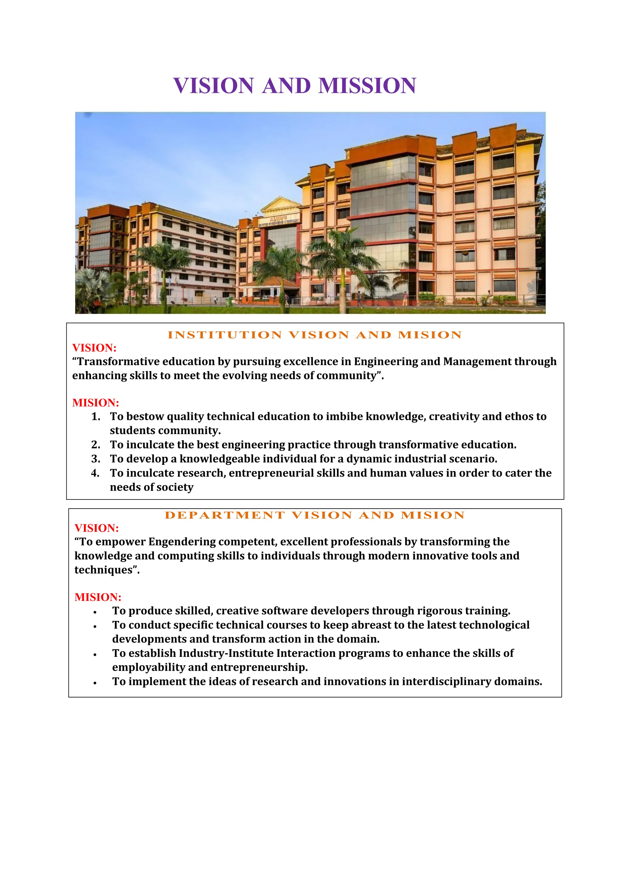
VISION AND MISSION
INSTITUTIONVISION AND MISION
VISION:
“Transformative education by pursuing excellence in Engineering and Management through
enhancing skills to meet the evolving needs of community”.
MISION:
1. To bestow quality technical education to imbibe knowledge, creativity and ethos to
students community.
2. To inculcate the best engineering practice through transformative education.
3. To develop a knowledgeable individual for a dynamic industrial scenario.
4. To inculcate research, entrepreneurial skills and human values in order to cater the
needs of society
DEPARTMENT VISION AND MISION
VISION:
“To empower Engendering competent, excellent professionals by transforming the
knowledge and computing skills to individuals through modern innovative tools and
techniques”.
MISION:
To produce skilled, creative software developers through rigorous training.
To conduct specific technical courses to keep abreast to the latest technological
developments and transform action in the domain.
To establish Industry-Institute Interaction programs to enhance the skills of
employability and entrepreneurship.
To implement the ideas of research and innovations in interdisciplinary domains.
3.
OUTCOMES (PO’s)
1. Engineeringknowledge: Apply the knowledge of mathematics, science,
engineering fundamentals, and an engineering specialization to the solution of
complex engineering problems.
2. Problem analysis: Identify, formulate, review research literature, and analyze
complex engineering problems reaching substantiated conclusions using first
principles of mathematics, natural sciences, and engineering sciences.
3. Design/development of solutions: Design solutions for complex engineering
problems and design system components or processes that meet the specified
needs with appropriate consideration forthe public health and safety, and the
cultural, societal, and environmental considerations.
4. Conduct investigations of complex problems: Use research-based knowledge and
research methods including design of experiments, analysis and interpretation
of data, and synthesis of the information to provide valid conclusions.
5. Modern tool usage: Create, select, and apply appropriate techniques, resources,
and modern engineering and IT tools including prediction and modeling to
complex engineering activities with an understanding of the limitations.
6. The engineer and society: Apply reasoning informed by the contextual
knowledge to assess societal, health, safety, legal and cultural issues and the
consequent responsibilities relevant to the professional engineering practice.
7. Environment and sustainability: Understand the impact of the professional
engineering solutions in societal and environmental contexts, and demonstrate
the knowledge of, and need for sustainable development.
8. Ethics: Apply ethical principles and commit to professional ethics,
responsibilities, and norms of the engineering practice.
9. Individual and teamwork: Function effectively as an individual, and as a member
or leader in diverse teams, and in multidisciplinary settings.
10. Communication: Communicate effectively on complex engineering activities
with the engineering community and with society, such as, being able to
comprehend and write effective reports and design documentation, make
effective presentations, and give and receive clear instructions.
11. Project management and finance: Demonstrate knowledge and understanding of
the engineering and management principles and apply these to one’s own work,
as a member and leader in a team, to manage projects and in multidisciplinary
environments.
12. Life-long learning: Recognize the need for, and have the preparation and ability
to engage in independent and life-long learning in the broadest context of
technological change
4.
PROGRAM SPECIFIC OUTCOMES(PSO’s)
A graduate of the Computer Science and Engineering Program will exhibit:
PSO1: Professional Skills: The ability to understand & implement the
computer programs in the areas of Computer Architecture, System
Software, Database Management Systems, Web Design, Multimedia and
Computer Networking.
PSO2: Problem-Solving Skills: The ability to solve real-world problems by suitable
mathematical model with strong technological concepts in rapidly growing arena
of computer technology.
PSO3: Successful Career and Entrepreneurship: Knowledge in diverse areas of
Software Engineering and Management &Entrepreneurship for IT Industry,
conducive in cultivating skills for successful career development.
PROGRAM EDUCATION OBJECTIVES
PEO1: Exhibit fundamental strength in core courses of Computer Engineering
to solve the problems of computing world.
PEO2: Adapt and contribute the emerging technological changes.
PEO3: Employed in computing profession or engaged in learning to
pursue higher studies.
5.
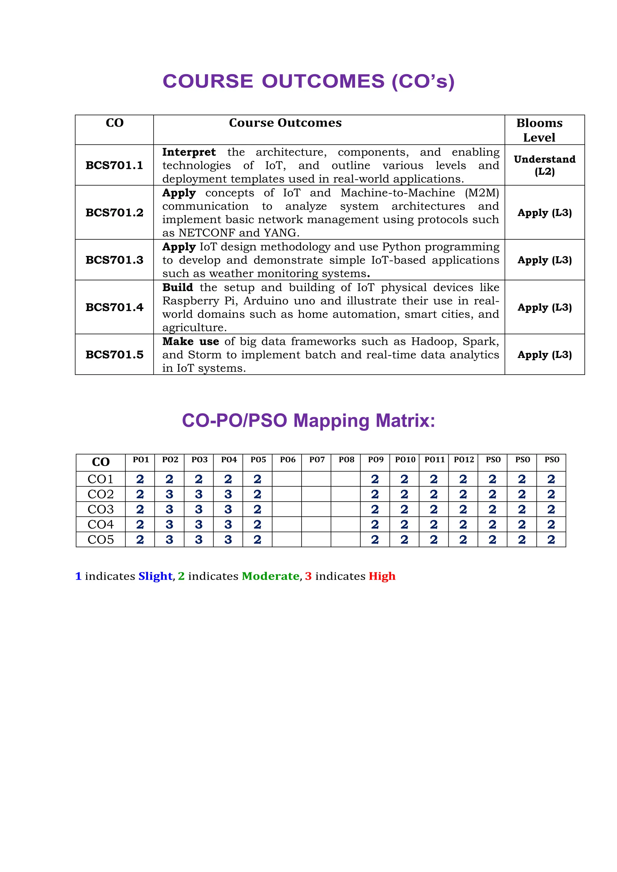
COURSE OUTCOMES (CO’s)
COCourse Outcomes Blooms
Level
BCS701.1
Interpret the architecture, components, and enabling
technologies of IoT, and outline various levels and
deployment templates used in real-world applications.
Understand
(L2)
BCS701.2
Apply concepts of IoT and Machine-to-Machine (M2M)
communication to analyze system architectures and
implement basic network management using protocols such
as NETCONF and YANG.
Apply (L3)
BCS701.3
Apply IoT design methodology and use Python programming
to develop and demonstrate simple IoT-based applications
such as weather monitoring systems.
Apply (L3)
BCS701.4
Build the setup and building of IoT physical devices like
Raspberry Pi, Arduino uno and illustrate their use in real-
world domains such as home automation, smart cities, and
agriculture.
Apply (L3)
BCS701.5
Make use of big data frameworks such as Hadoop, Spark,
and Storm to implement batch and real-time data analytics
in IoT systems.
Apply (L3)
CO-PO/PSO Mapping Matrix:
CO PO1 PO2 PO3 PO4 PO5 PO6 PO7 PO8 PO9 PO10 PO11 PO12 PSO PSO PSO
CO1 2 2 2 2 2 2 2 2 2 2 2 2
CO2 2 3 3 3 2 2 2 2 2 2 2 2
CO3 2 3 3 3 2 2 2 2 2 2 2 2
CO4 2 3 3 3 2 2 2 2 2 2 2 2
CO5 2 3 3 3 2 2 2 2 2 2 2 2
1 indicates Slight, 2 indicates Moderate, 3 indicates High
6.
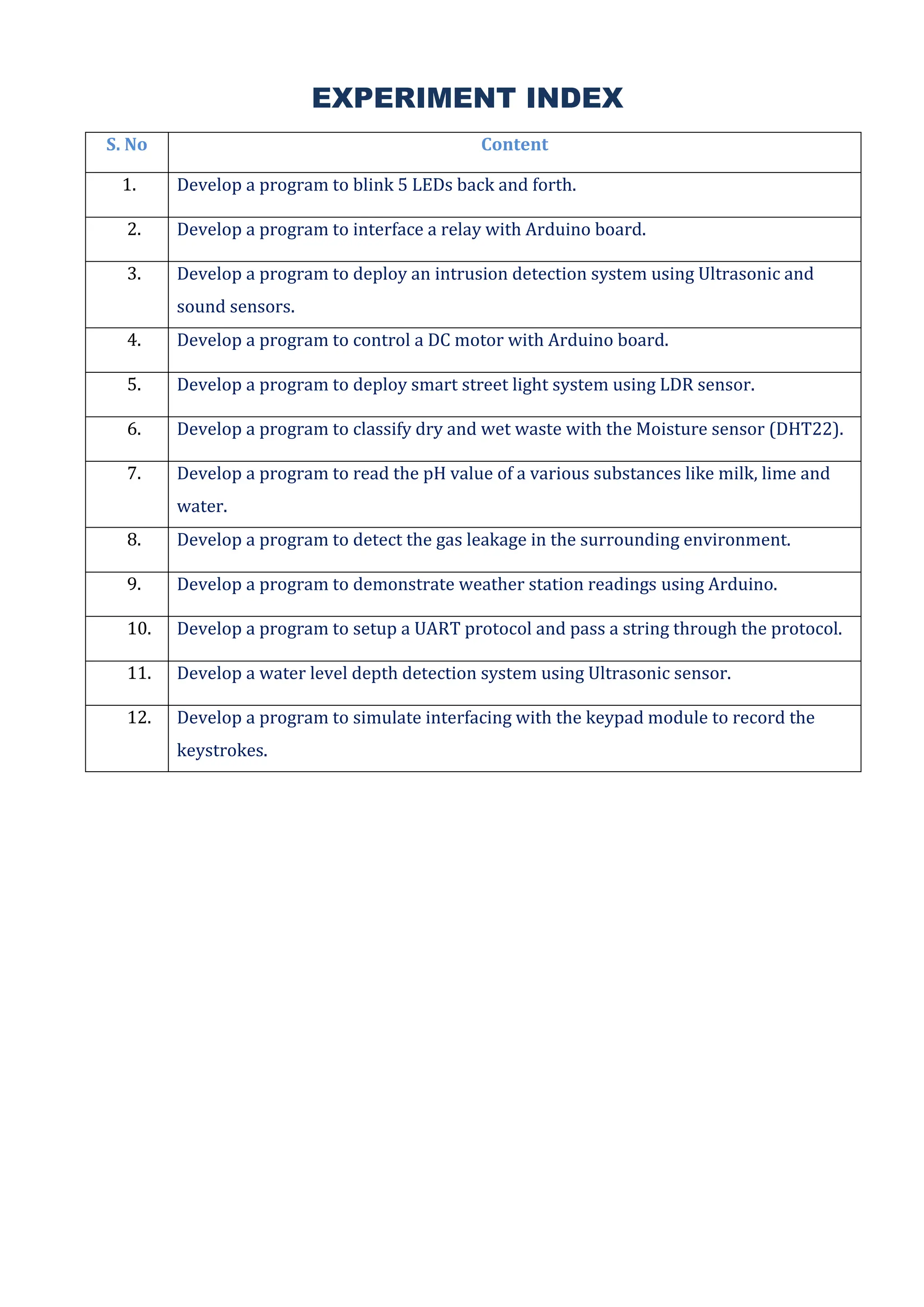
EXPERIMENT INDEX
S. NoContent
1. Develop a program to blink 5 LEDs back and forth.
2. Develop a program to interface a relay with Arduino board.
3. Develop a program to deploy an intrusion detection system using Ultrasonic and
sound sensors.
4. Develop a program to control a DC motor with Arduino board.
5. Develop a program to deploy smart street light system using LDR sensor.
6. Develop a program to classify dry and wet waste with the Moisture sensor (DHT22).
7. Develop a program to read the pH value of a various substances like milk, lime and
water.
8. Develop a program to detect the gas leakage in the surrounding environment.
9. Develop a program to demonstrate weather station readings using Arduino.
10. Develop a program to setup a UART protocol and pass a string through the protocol.
11. Develop a water level depth detection system using Ultrasonic sensor.
12. Develop a program to simulate interfacing with the keypad module to record the
keystrokes.
7.
BCS701
Dept. of CSE,AIET, Mangalore Page 2
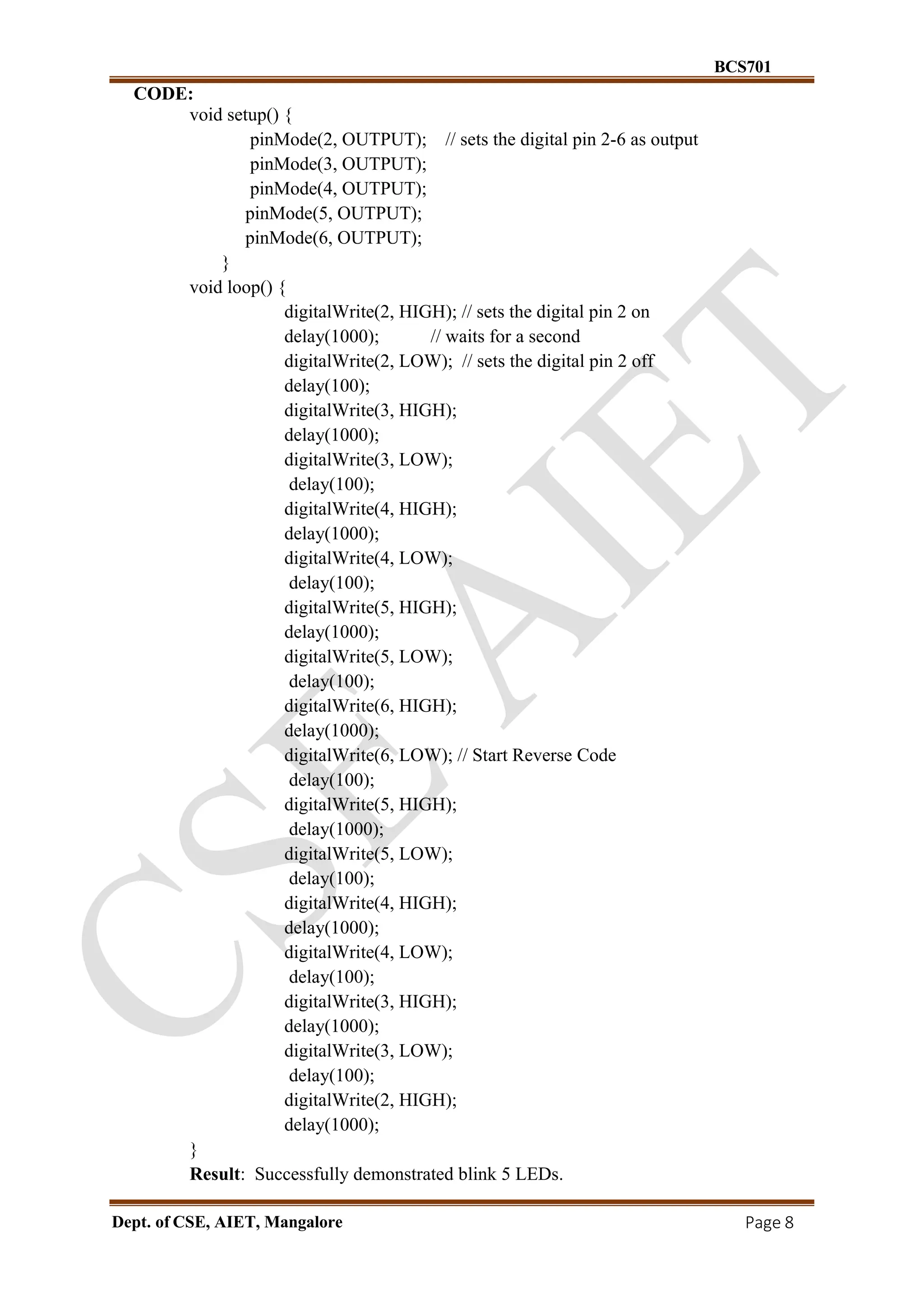
Exp. No. 1
Develop a program to blink 5 LEDs back and forth.
AIM: Develop a program to blink 5 LEDs back and forth.
COMPONENT:
S.NO. Name Quantity
1. Ardiuno Uno 1
2. Jumper Cable 6
3. Bread Board 1
4. LED 5
5. Resistance (800 Ω) 5
CIRCUIT DIAGRAM:
SET UP:
a) Connect the circuit as per circuit.
b) Make sure VCC and Ground pins connected properly to avoid any damage to Arduino board.
c) Open Arduino IDE then goto tools and select appropriate Arduino board.
d) Select tool then select the port select the com port to which board is connected.
e) Type sketch (Program) and upload to board.
8.
BCS701
Dept. of CSE,AIET, Mangalore Page 8
CODE:
void setup() {
pinMode(2, OUTPUT); // sets the digital pin 2-6 as output
pinMode(3, OUTPUT);
pinMode(4, OUTPUT);
pinMode(5, OUTPUT);
pinMode(6, OUTPUT);
}
void loop() {
digitalWrite(2, HIGH); // sets the digital pin 2 on
delay(1000); // waits for a second
digitalWrite(2, LOW); // sets the digital pin 2 off
delay(100);
digitalWrite(3, HIGH);
delay(1000);
digitalWrite(3, LOW);
delay(100);
digitalWrite(4, HIGH);
delay(1000);
digitalWrite(4, LOW);
delay(100);
digitalWrite(5, HIGH);
delay(1000);
digitalWrite(5, LOW);
delay(100);
digitalWrite(6, HIGH);
delay(1000);
digitalWrite(6, LOW); // Start Reverse Code
delay(100);
digitalWrite(5, HIGH);
delay(1000);
digitalWrite(5, LOW);
delay(100);
digitalWrite(4, HIGH);
delay(1000);
digitalWrite(4, LOW);
delay(100);
digitalWrite(3, HIGH);
delay(1000);
digitalWrite(3, LOW);
delay(100);
digitalWrite(2, HIGH);
delay(1000);
}
Result: Successfully demonstrated blink 5 LEDs.
9.
BCS701
Dept. of CSE,AIET, Mangalore Page 9
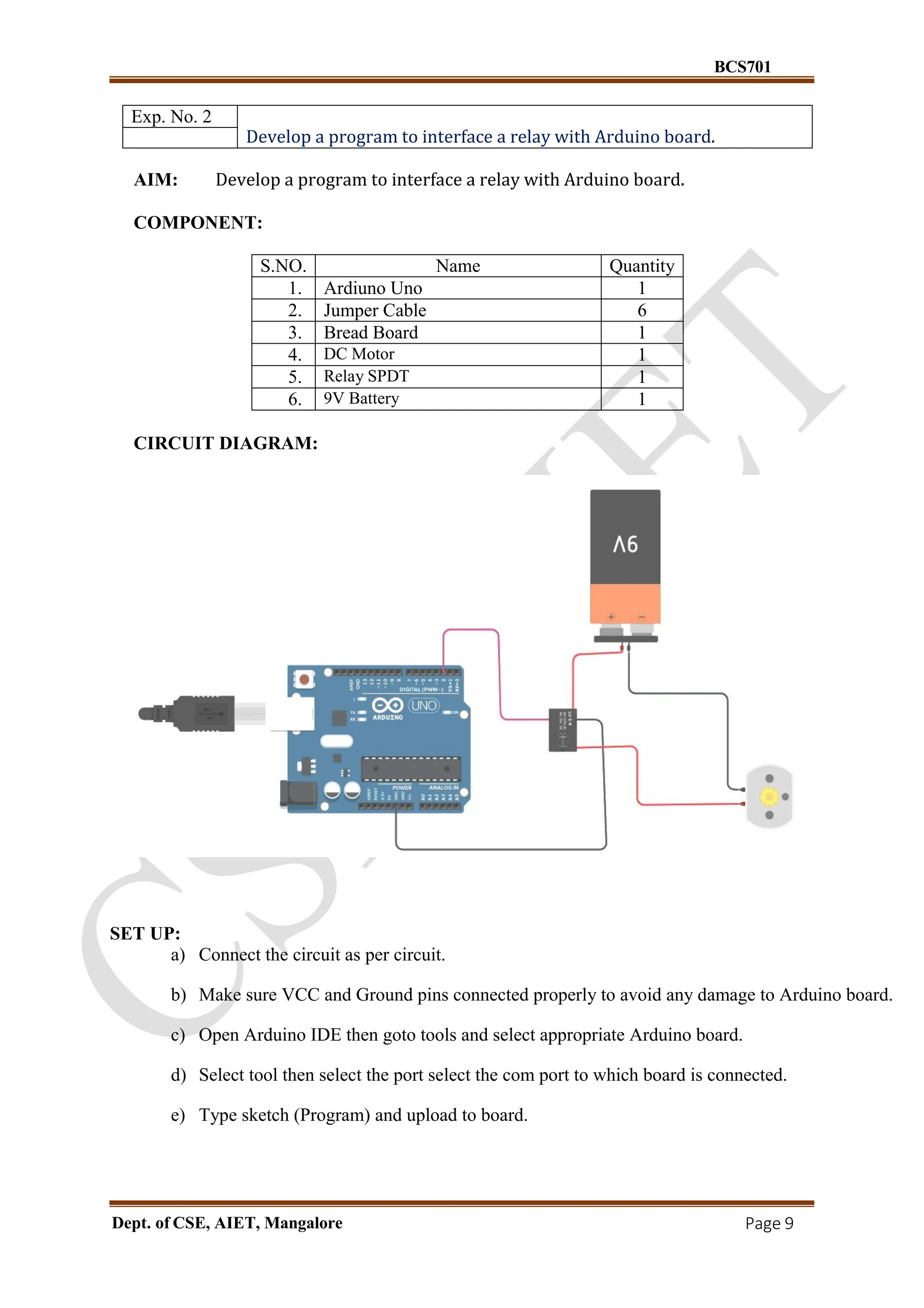
Exp. No. 2
Develop a program to interface a relay with Arduino board.
AIM: Develop a program to interface a relay with Arduino board.
COMPONENT:
S.NO. Name Quantity
1. Ardiuno Uno 1
2. Jumper Cable 6
3. Bread Board 1
4. DC Motor 1
5. Relay SPDT 1
6. 9V Battery 1
CIRCUIT DIAGRAM:
SET UP:
a) Connect the circuit as per circuit.
b) Make sure VCC and Ground pins connected properly to avoid any damage to Arduino board.
c) Open Arduino IDE then goto tools and select appropriate Arduino board.
d) Select tool then select the port select the com port to which board is connected.
e) Type sketch (Program) and upload to board.
10.
BCS701
Dept. of CSE,AIET, Mangalore Page 10
CODE:
void setup()
{
pinMode(2, OUTPUT);
}
void loop()
{
digitalWrite(2, HIGH);
delay(10000); // Wait for 1000 millisecond(s)
digitalWrite(2, LOW);
delay(5000); // Wait for 1000 millisecond(s)
}
Result: Successfully demonstrated interface a relay with Arduino board
11.
BCS701
Dept. of CSE,AIET, Mangalore Page 11
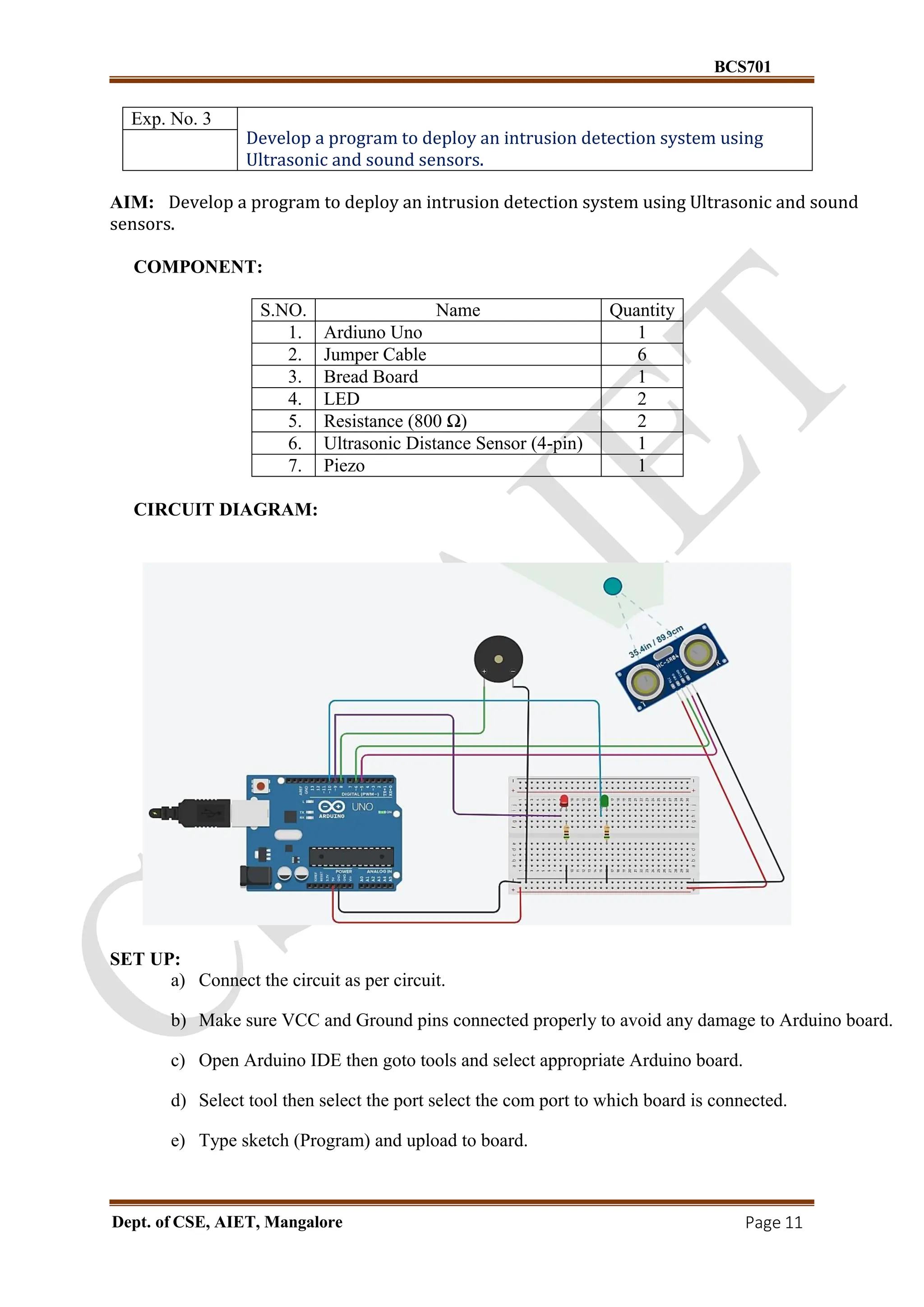
Exp. No. 3
Develop a program to deploy an intrusion detection system using
Ultrasonic and sound sensors.
AIM: Develop a program to deploy an intrusion detection system using Ultrasonic and sound
sensors.
COMPONENT:
S.NO. Name Quantity
1. Ardiuno Uno 1
2. Jumper Cable 6
3. Bread Board 1
4. LED 2
5. Resistance (800 Ω) 2
6. Ultrasonic Distance Sensor (4-pin) 1
7. Piezo 1
CIRCUIT DIAGRAM:
SET UP:
a) Connect the circuit as per circuit.
b) Make sure VCC and Ground pins connected properly to avoid any damage to Arduino board.
c) Open Arduino IDE then goto tools and select appropriate Arduino board.
d) Select tool then select the port select the com port to which board is connected.
e) Type sketch (Program) and upload to board.
12.
BCS701
Dept. of CSE,AIET, Mangalore Page 12
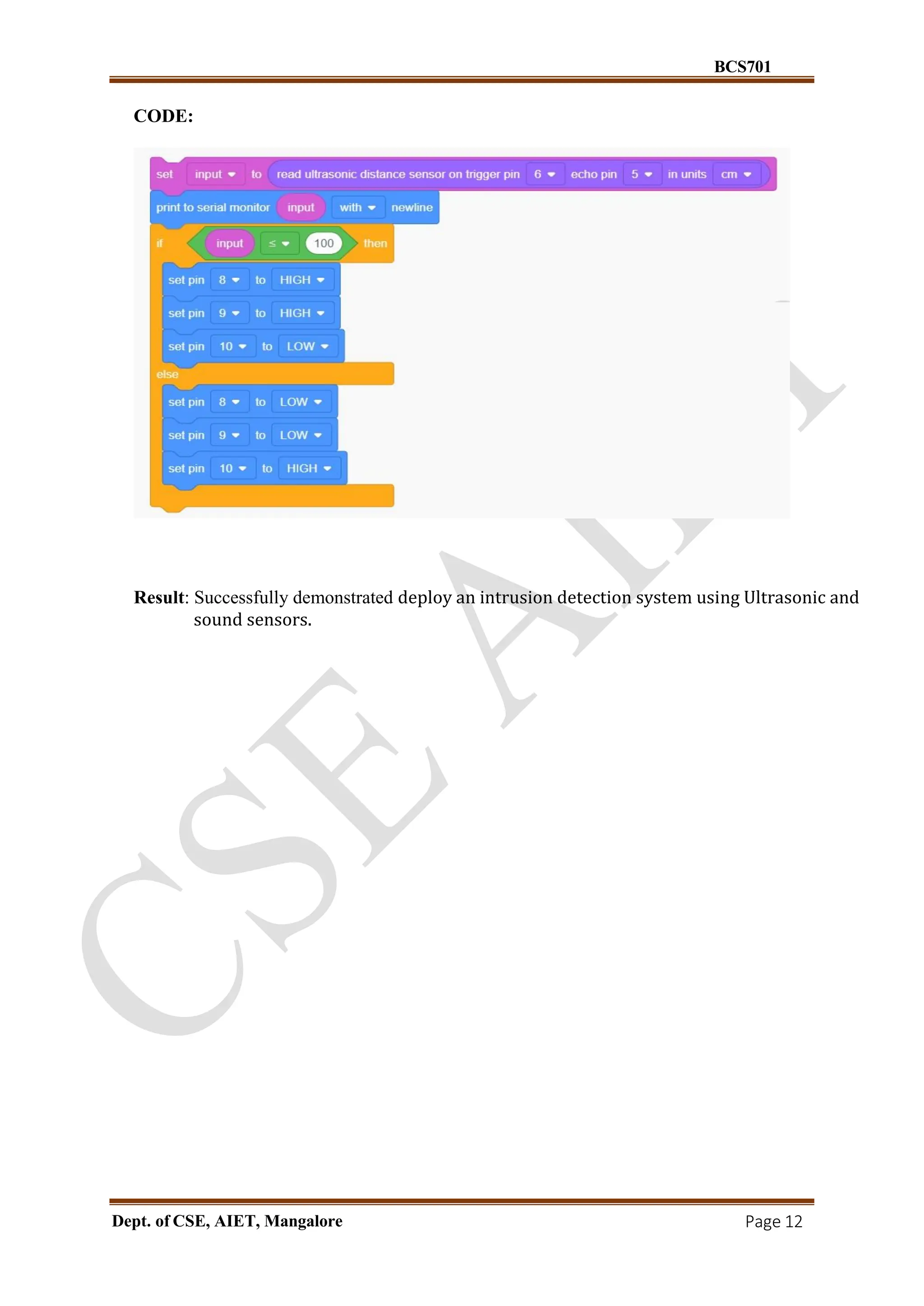
CODE:
Result: Successfully demonstrated deploy an intrusion detection system using Ultrasonic and
sound sensors.
13.
BCS701
Dept. of CSE,AIET, Mangalore Page 13
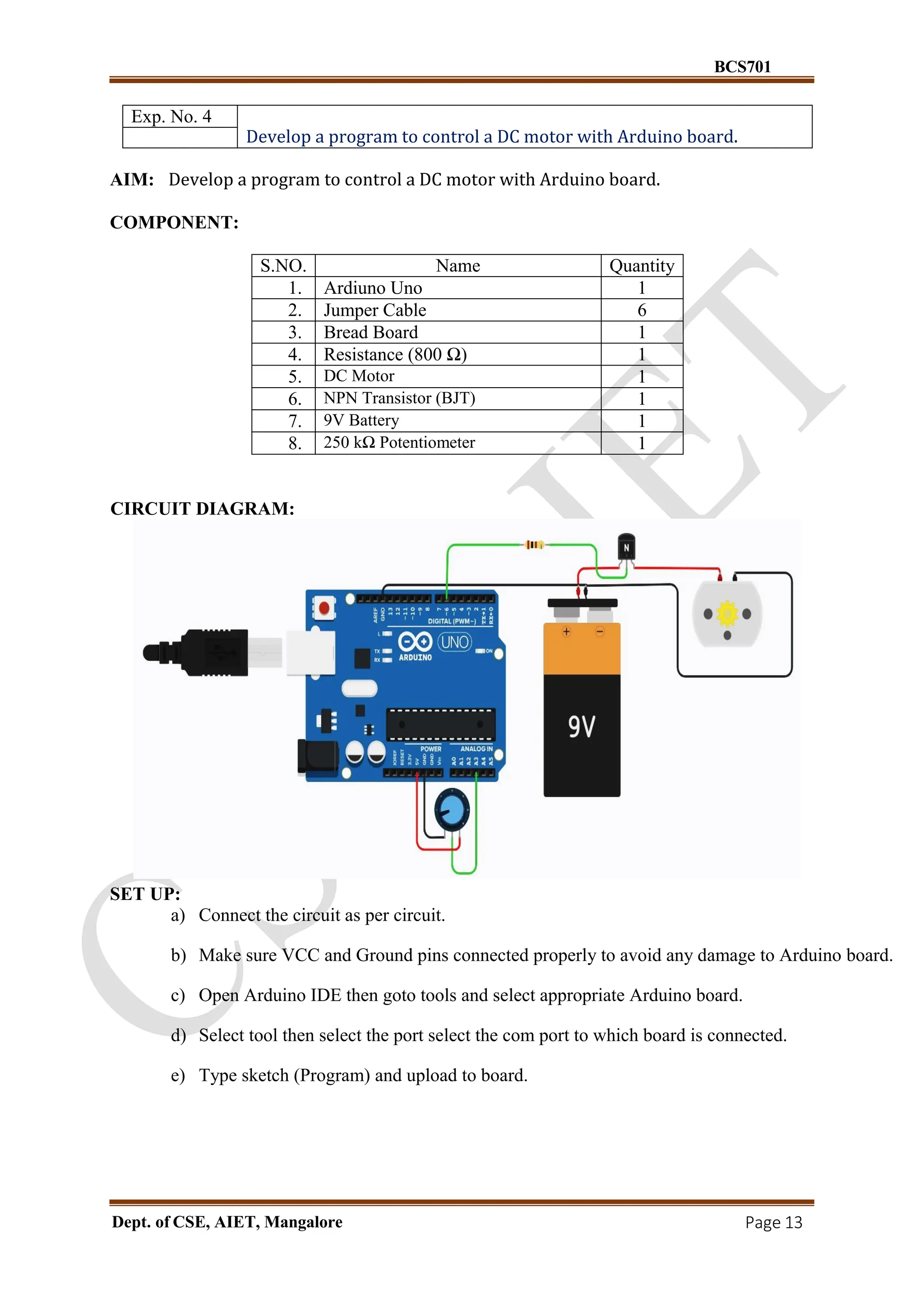
Exp. No. 4
Develop a program to control a DC motor with Arduino board.
AIM: Develop a program to control a DC motor with Arduino board.
COMPONENT:
S.NO. Name Quantity
1. Ardiuno Uno 1
2. Jumper Cable 6
3. Bread Board 1
4. Resistance (800 Ω) 1
5. DC Motor 1
6. NPN Transistor (BJT) 1
7. 9V Battery 1
8. 250 kΩ Potentiometer 1
CIRCUIT DIAGRAM:
SET UP:
a) Connect the circuit as per circuit.
b) Make sure VCC and Ground pins connected properly to avoid any damage to Arduino board.
c) Open Arduino IDE then goto tools and select appropriate Arduino board.
d) Select tool then select the port select the com port to which board is connected.
e) Type sketch (Program) and upload to board.
14.
BCS701
Dept. of CSE,AIET, Mangalore Page 14
CODE:
const int poten = A3;
int var;
void setup()
{
pinMode(6, OUTPUT);
}
void loop()
{
var = analogRead(poten);
analogWrite(6,var);
}
Result: Successfully demonstrated control a DC motor with Arduino board
15.
BCS701
Dept. of CSE,AIET, Mangalore Page 15
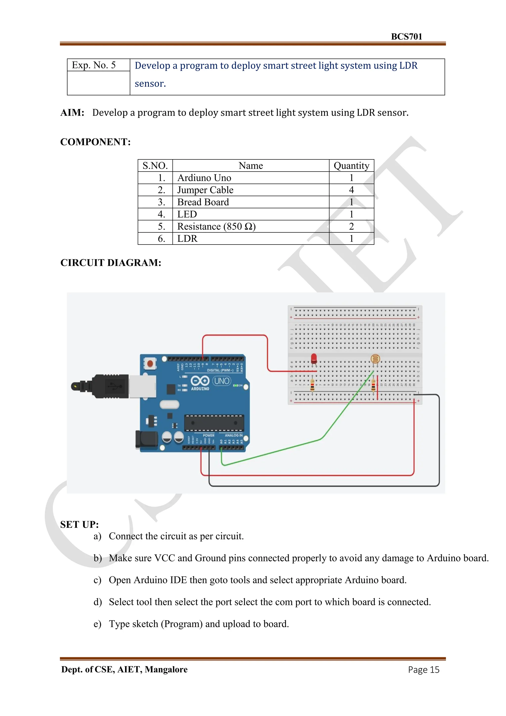
Exp. No. 5 Develop a program to deploy smart street light system using LDR
sensor.
AIM: Develop a program to deploy smart street light system using LDR sensor.
COMPONENT:
S.NO. Name Quantity
1. Ardiuno Uno 1
2. Jumper Cable 4
3. Bread Board 1
4. LED 1
5. Resistance (850 Ω) 2
6. LDR 1
CIRCUIT DIAGRAM:
SET UP:
a) Connect the circuit as per circuit.
b) Make sure VCC and Ground pins connected properly to avoid any damage to Arduino board.
c) Open Arduino IDE then goto tools and select appropriate Arduino board.
d) Select tool then select the port select the com port to which board is connected.
e) Type sketch (Program) and upload to board.
16.
BCS701
Dept. of CSE,AIET, Mangalore Page 16
CODE:
int sensorPin = A0;
int sensorValue = 0;
int led = 9;
void setup() {
pinMode(led, OUTPUT);
Serial.begin(9600);
}
void loop(){
sensorValue = analogRead(sensorPin);
Serial.println(sensorValue);
if(sensorValue < 100){
Serial.println("LED light on");
digitalWrite(led,HIGH);
delay(1000);
}
digitalWrite(led,LOW);
delay(sensorValue);
}
Result: Successfully demonstrated deploy smart street light system using LDR sensor
17.
BCS701
Dept. of CSE,AIET, Mangalore Page 17
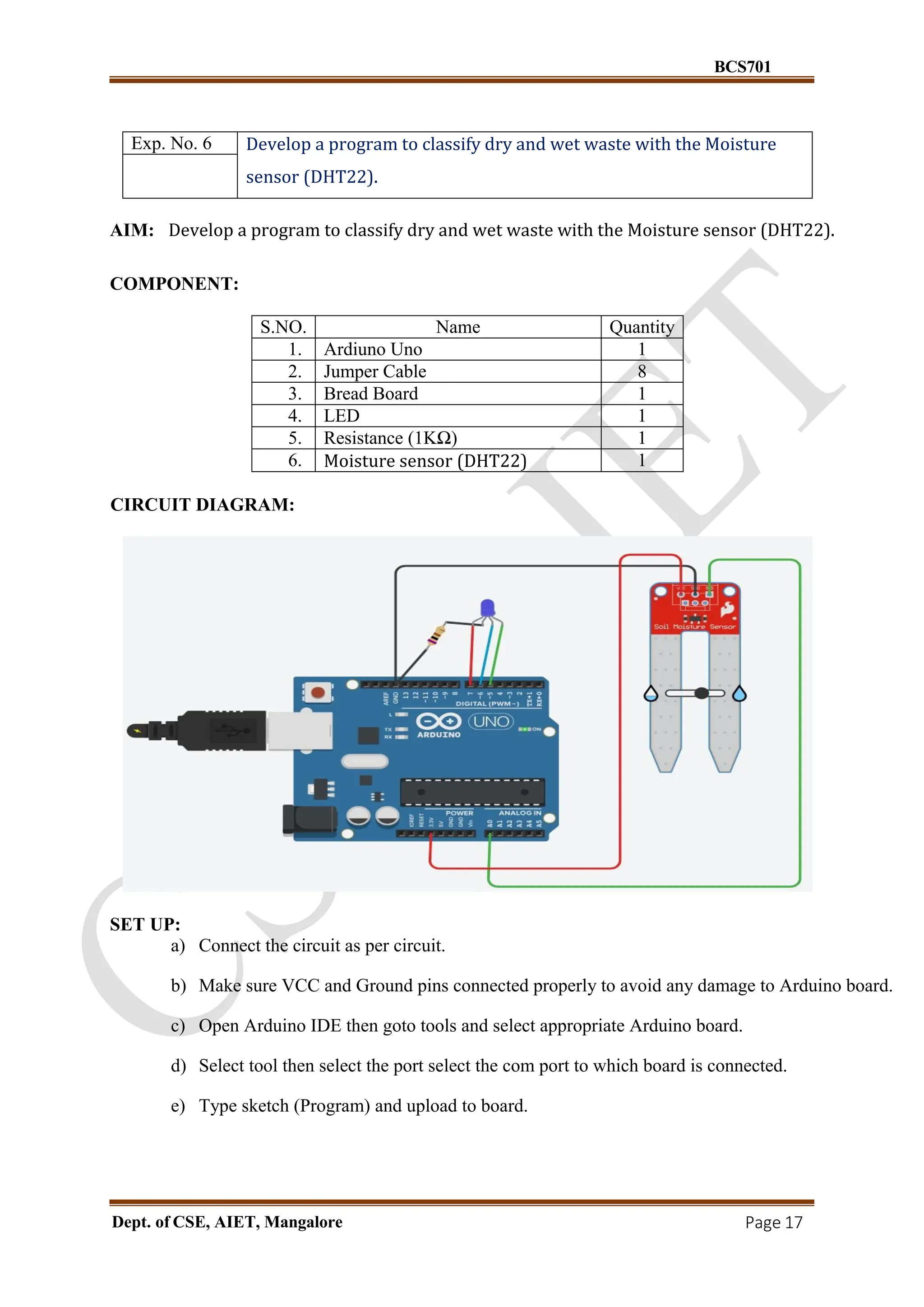
Exp. No. 6 Develop a program to classify dry and wet waste with the Moisture
sensor (DHT22).
AIM: Develop a program to classify dry and wet waste with the Moisture sensor (DHT22).
COMPONENT:
S.NO. Name Quantity
1. Ardiuno Uno 1
2. Jumper Cable 8
3. Bread Board 1
4. LED 1
5. Resistance (1KΩ) 1
6. Moisture sensor (DHT22) 1
CIRCUIT DIAGRAM:
SET UP:
a) Connect the circuit as per circuit.
b) Make sure VCC and Ground pins connected properly to avoid any damage to Arduino board.
c) Open Arduino IDE then goto tools and select appropriate Arduino board.
d) Select tool then select the port select the com port to which board is connected.
e) Type sketch (Program) and upload to board.
18.
BCS701
Dept. of CSE,AIET, Mangalore Page 18
CODE:
int moistureValue;
float moisture_percentage;
void setup()
{
pinMode(7, OUTPUT);
pinMode(6, OUTPUT);
pinMode(5, OUTPUT);
Serial.begin(9600);
}
void loop()
{
moistureValue = analogRead(A0);
moisture_percentage = ((moistureValue/539.00)*100);
if ( moisture_percentage>0 && moisture_percentage<25 )
{ digitalWrite(7,HIGH);
digitalWrite(6,LOW);
digitalWrite(5,LOW);
}
if ( moisture_percentage>25 && moisture_percentage<80 )
{ digitalWrite(7,LOW);
digitalWrite(6,HIGH);
digitalWrite(5,LOW);
}
if ( moisture_percentage>80 && moisture_percentage<100 )
{ digitalWrite(7,LOW);
digitalWrite(6,LOW);
digitalWrite(5,HIGH);
}
Serial.print("nMoisture Value : ");
Serial.print(moisture_percentage);
Serial.print("%");
delay(1000);
}
Result: Successfully demonstrated dry and wet waste with the Moisture sensor (DHT22)
19.
BCS701
Dept. of CSE,AIET, Mangalore Page 19
Exp. No. 7 Develop a program to read the pH value of a various substances like
milk, lime and water.
AIM: Develop a program to read the pH value of a various substances like milk, lime and water.
COMPONENT:
S.NO. Name Quantity
1. Ardiuno Uno 1
2. Jumper Cable 12
3. Bread Board 1
4. Resistance (220 Ω) 1
5. LCD 16 x 2 1
6. 10 MΩ Potentiometer 1
7. 5V Regulator [LM7805] 1
8. 0.22 uF Capacitor 1
9. 0.1 uF Capacitor 1
CIRCUIT DIAGRAM:
SET UP:
a) Connect the circuit as per circuit.
b) Make sure VCC and Ground pins connected properly to avoid any damage to Arduino board.
c) Open Arduino IDE then goto tools and select appropriate Arduino board.
d) Select tool then select the port select the com port to which board is connected.
e) Type sketch (Program) and upload to board.
20.
BCS701
Dept. of CSE,AIET, Mangalore Page 20
CODE:
#include<LiquidCrystal.h>
const int rs =13,en = 12,d4 =11,d5 =10,d6 =9,d7 =8;
LiquidCrystal lcd(rs,en, d4,d5,d6,d7);
int Contrast = 0;
void setup()
{
Serial.begin(9600);
analogWrite (6,Contrast);
lcd.begin(16,2);
lcd.setCursor(4,0);
lcd.print("pH Value:");
}
void loop()
{
int sensorValue = analogRead(A0);
float ph = sensorValue * (14.0/1023.0);
Serial.println(ph);
lcd.setCursor(6,1);
if (ph>0.0 && ph<5.0)
{
lcd.print (ph);
lcd.print (" ACID");
}
if (ph>5.0 &&ph<7.0)
{
lcd.print (ph);
lcd.print (" Normal");
}
if (ph>7.0 && ph<14.0)
lcd.print (ph);
{
lcd.print (" Base");
}
}
Result: Successfully demonstrated read the pH value of a various substances like milk, lime
and water
21.
BCS701
Dept. of CSE,AIET, Mangalore Page 21
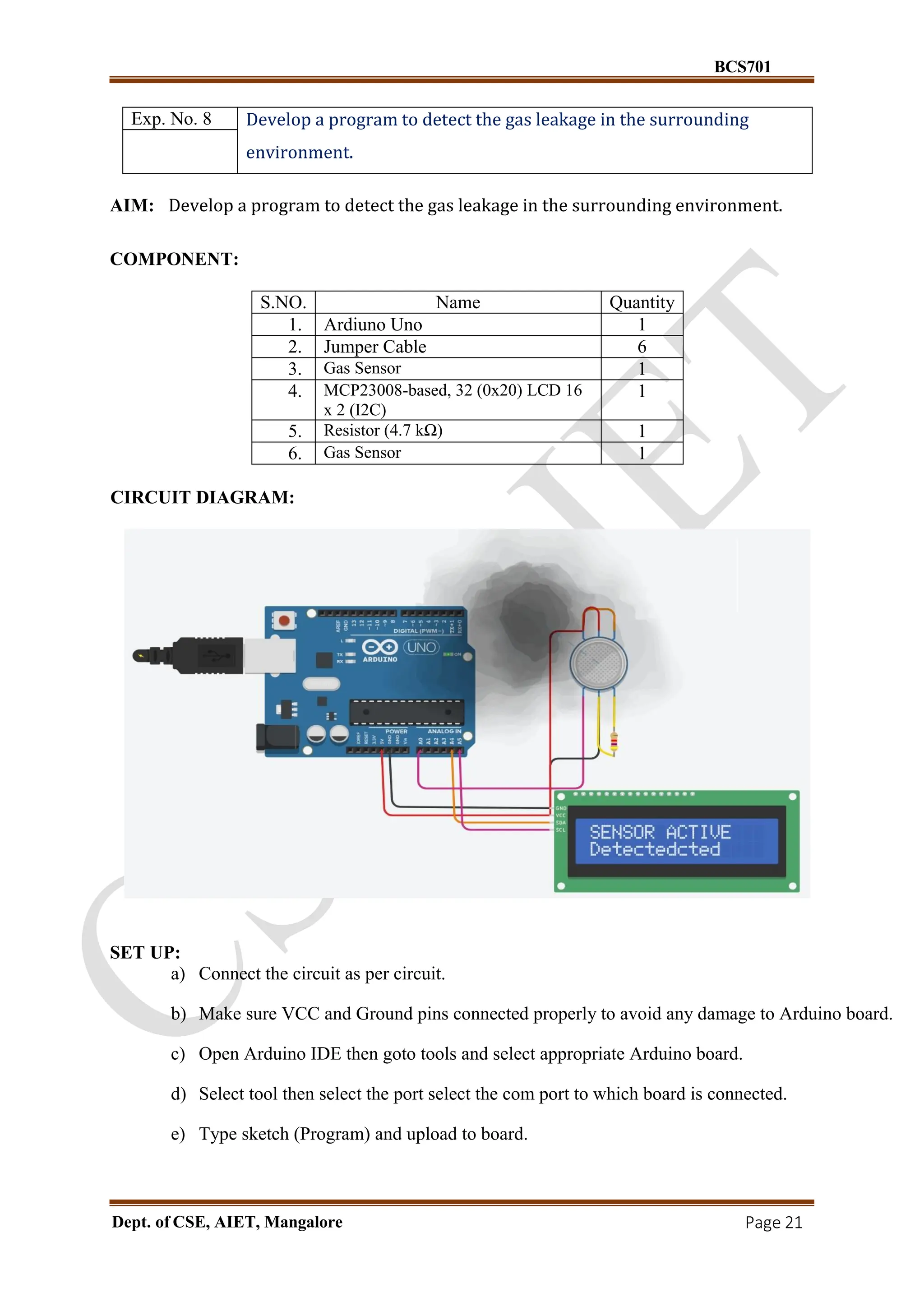
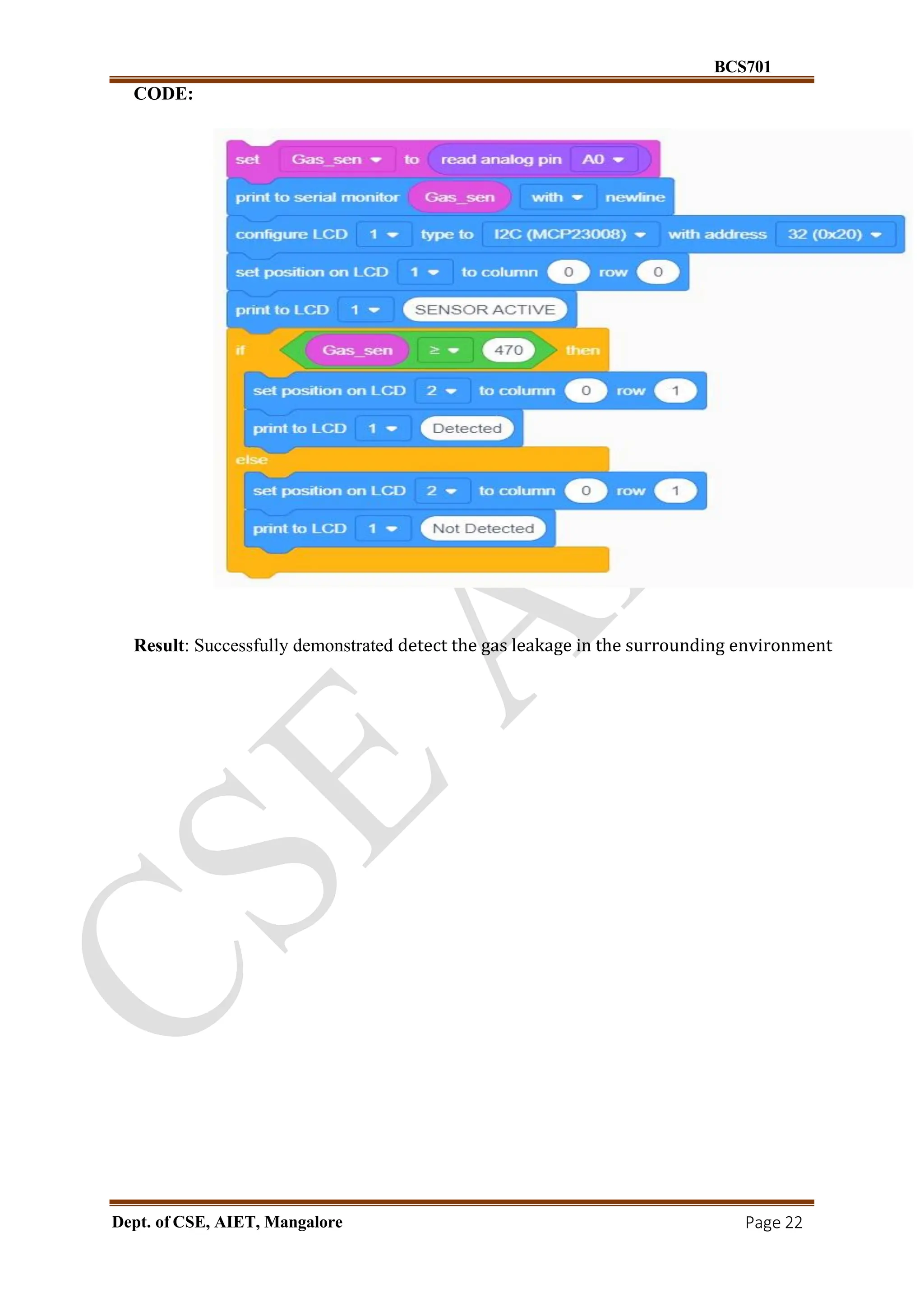
Exp. No. 8 Develop a program to detect the gas leakage in the surrounding
environment.
AIM: Develop a program to detect the gas leakage in the surrounding environment.
COMPONENT:
S.NO. Name Quantity
1. Ardiuno Uno 1
2. Jumper Cable 6
3. Gas Sensor 1
4. MCP23008-based, 32 (0x20) LCD 16
x 2 (I2C)
1
5. Resistor (4.7 kΩ) 1
6. Gas Sensor 1
CIRCUIT DIAGRAM:
SET UP:
a) Connect the circuit as per circuit.
b) Make sure VCC and Ground pins connected properly to avoid any damage to Arduino board.
c) Open Arduino IDE then goto tools and select appropriate Arduino board.
d) Select tool then select the port select the com port to which board is connected.
e) Type sketch (Program) and upload to board.
22.
BCS701
Dept. of CSE,AIET, Mangalore Page 22
CODE:
Result: Successfully demonstrated detect the gas leakage in the surrounding environment
23.
BCS701
Dept. of CSE,AIET, Mangalore Page 23
Exp. No. 9 Develop a program to demonstrate weather station readings using
Arduino.
AIM: Develop a program to demonstrate weather station readings using Arduino.
COMPONENT:
S.NO. Name Quantity
1. Ardiuno Uno 1
2. Jumper Cable 10
3. Bread Board 1
4. LED 2
5. Resistance (1KΩ) 7
6. LCD 16 x 2 (I2C) 1
7. Potentiometer (250 kΩ) 1
8. Temperature Sensor [TMP36] 1
9. Soil Moisture Sensor 1
10. Push Button 5
CIRCUIT DIAGRAM:
SET UP:
a) Connect the circuit as per circuit.
b) Make sure VCC and Ground pins connected properly to avoid any damage to Arduino board.
c) Open Arduino IDE then goto tools and select appropriate Arduino board.
d) Select tool then select the port select the com port to which board is connected.
e) Type sketch (Program) and upload to board.
BCS701
Dept. of CSE,AIET, Mangalore Page 28
currentScreen = i;
updateDisplay();
delay(300);
}
}
}
void setup() {
lcd.begin(16, 2);
lcd.setBacklight(1);
Serial.begin(9600);
for (int i = 0; i < 4; i++) pinMode(buttonPins[i], INPUT_PULLUP);
for (int i = 0; i < 2; i++) pinMode(ledPins[i], OUTPUT);
lcd.setCursor(0, 0);
lcd.print("Weather Station");
delay(2000);
lcd.clear();
}
void loop() {
readSensors();
checkAlerts();
updateDisplay();
handleButtonPress();
calculateWeatherForecast();
delay(2000);
}
Result: Successfully demonstrated weather station readings using Arduino
29.
BCS701
Dept. of CSE,AIET, Mangalore Page 29
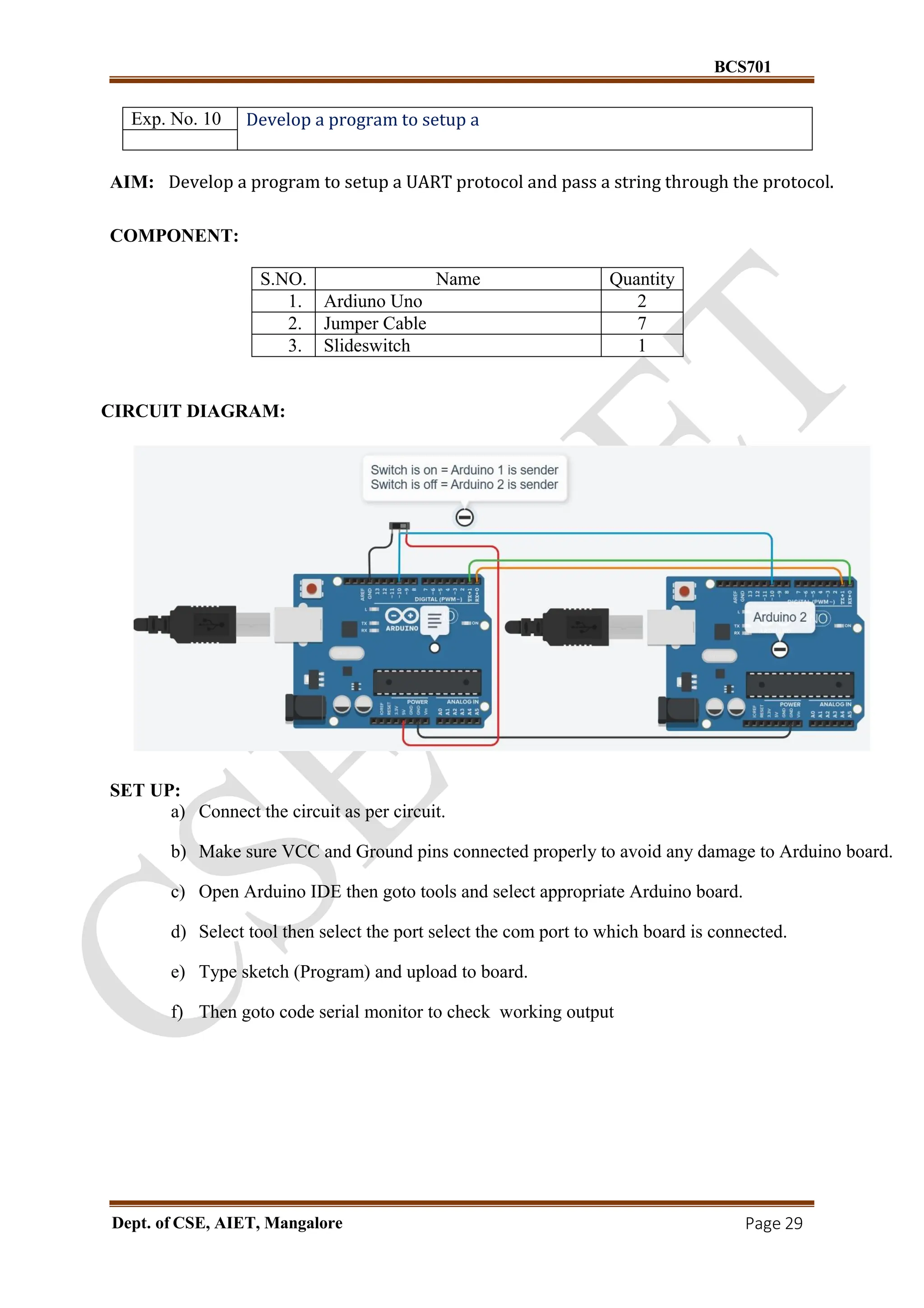
Exp. No. 10 Develop a program to setup a
AIM: Develop a program to setup a UART protocol and pass a string through the protocol.
COMPONENT:
S.NO. Name Quantity
1. Ardiuno Uno 2
2. Jumper Cable 7
3. Slideswitch 1
CIRCUIT DIAGRAM:
SET UP:
a) Connect the circuit as per circuit.
b) Make sure VCC and Ground pins connected properly to avoid any damage to Arduino board.
c) Open Arduino IDE then goto tools and select appropriate Arduino board.
d) Select tool then select the port select the com port to which board is connected.
e) Type sketch (Program) and upload to board.
f) Then goto code serial monitor to check working output
30.
BCS701
Dept. of CSE,AIET, Mangalore Page 30
CODE:
const int MAX_LEN =30;
char sendMsg[MAX_LEN] = "Hello i'm Arduino-2n";
char receiveMsg[MAX_LEN];
int switchState = 1; // Active HIGH input
int switch_pin = 10;
void setup() {
Serial.begin(9600);
pinMode(switch_pin, INPUT);
}
void loop() {
switchState = digitalRead(switch_pin);
if (switchState == HIGH) {
// Receive if switch is off
if (Serial.available() > 0) {
int len = Serial.parseInt(); // Read the length as number
Serial.read(); // Consume the newline after the number
int n = Serial.readBytes(receiveMsg, len);
receiveMsg[n] = '0'; // Null-terminate the received string
Serial.print("Message = ");
Serial.println(receiveMsg);
}
} else {
// Send if switch is on
int len = strlen(sendMsg);
Serial.write(receiveMsg, len); // send raw message
delay(1000);
}
}
Result: Successfully demonstrated UART using two Arduino
31.
BCS701
Dept. of CSE,AIET, Mangalore Page 31
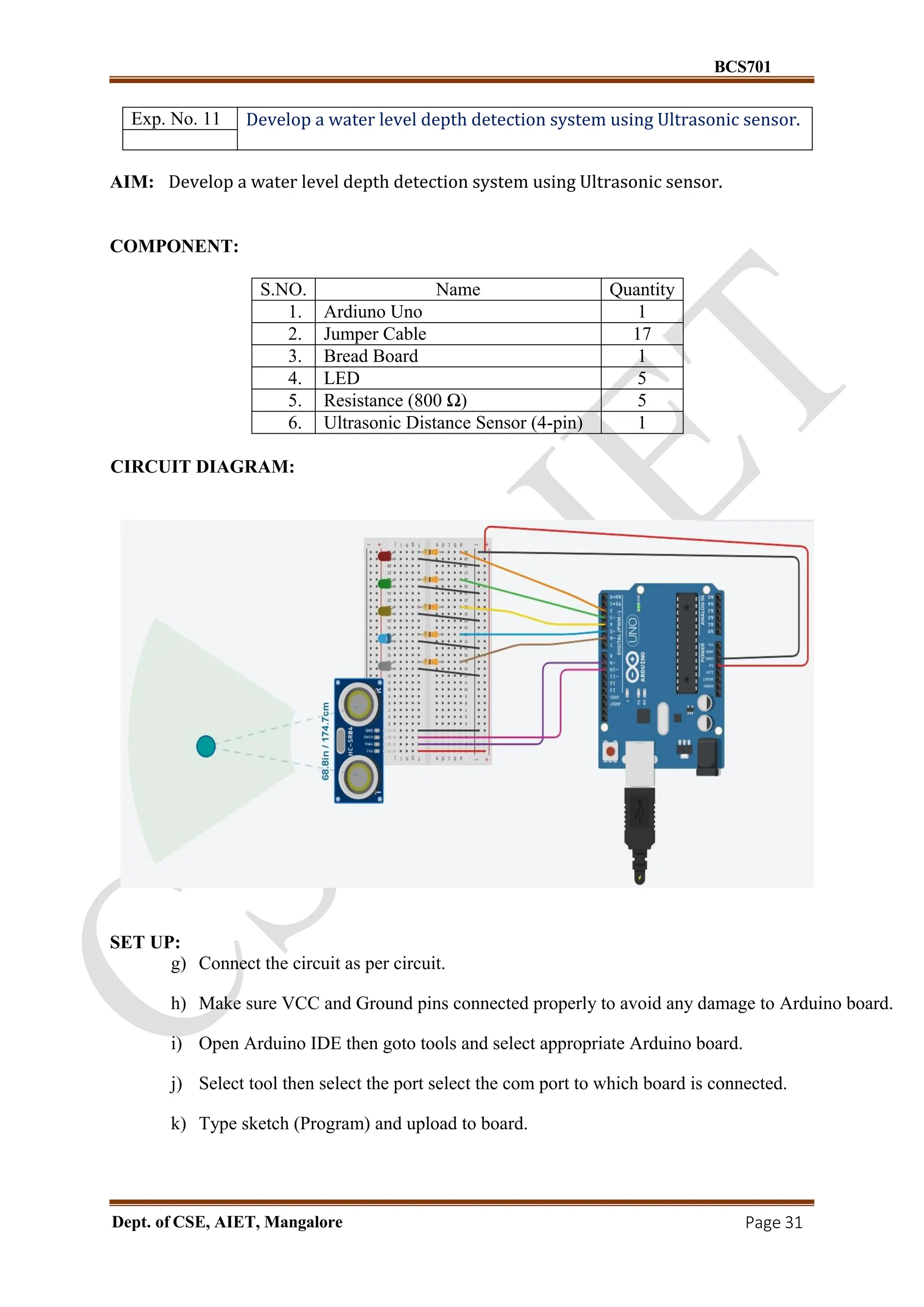
Exp. No. 11 Develop a water level depth detection system using Ultrasonic sensor.
AIM: Develop a water level depth detection system using Ultrasonic sensor.
COMPONENT:
S.NO. Name Quantity
1. Ardiuno Uno 1
2. Jumper Cable 17
3. Bread Board 1
4. LED 5
5. Resistance (800 Ω) 5
6. Ultrasonic Distance Sensor (4-pin) 1
CIRCUIT DIAGRAM:
SET UP:
g) Connect the circuit as per circuit.
h) Make sure VCC and Ground pins connected properly to avoid any damage to Arduino board.
i) Open Arduino IDE then goto tools and select appropriate Arduino board.
j) Select tool then select the port select the com port to which board is connected.
k) Type sketch (Program) and upload to board.
BCS701
Dept. of CSE,AIET, Mangalore Page 34
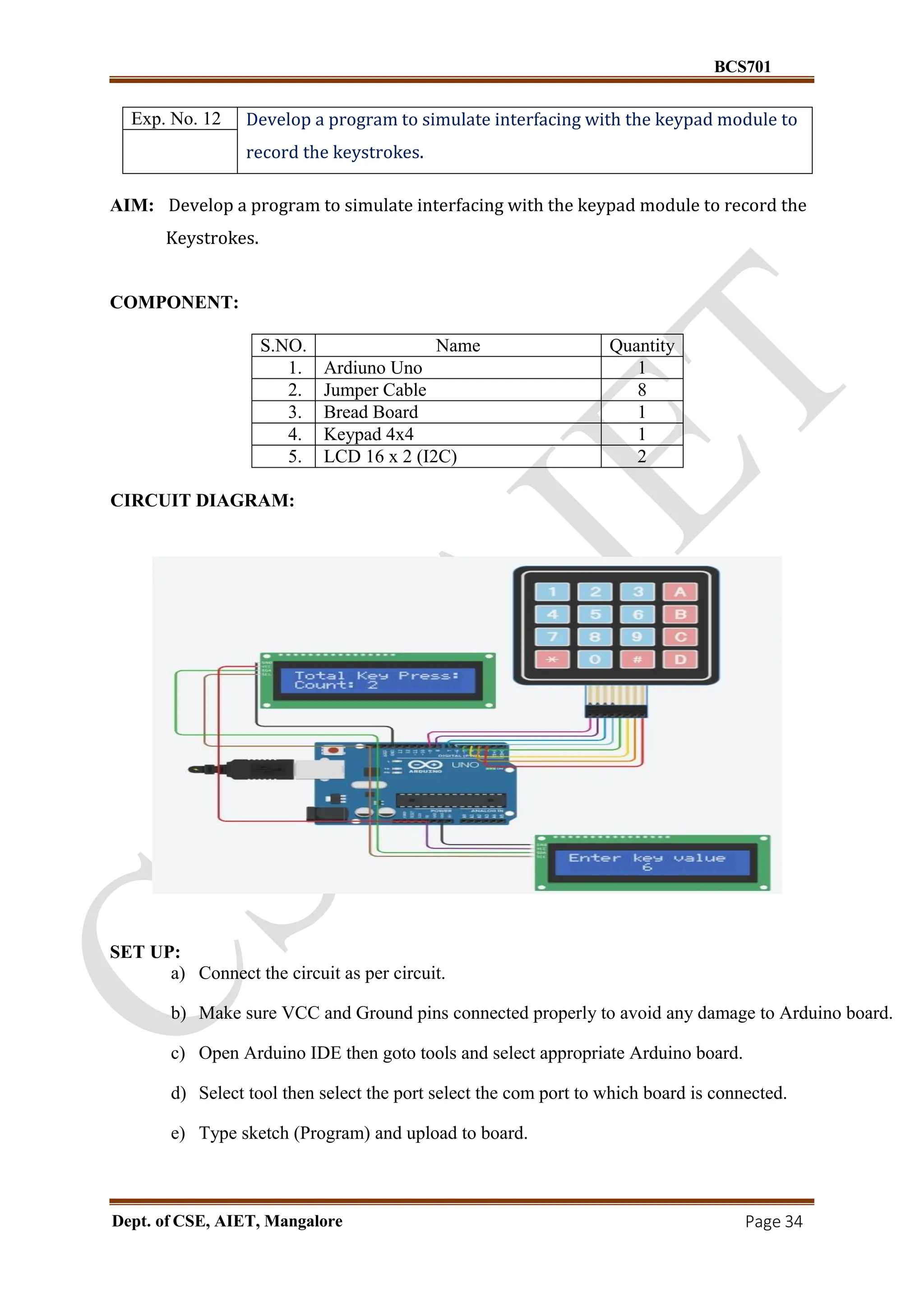
Exp. No. 12 Develop a program to simulate interfacing with the keypad module to
record the keystrokes.
AIM: Develop a program to simulate interfacing with the keypad module to record the
Keystrokes.
COMPONENT:
S.NO. Name Quantity
1. Ardiuno Uno 1
2. Jumper Cable 8
3. Bread Board 1
4. Keypad 4x4 1
5. LCD 16 x 2 (I2C) 2
CIRCUIT DIAGRAM:
SET UP:
a) Connect the circuit as per circuit.
b) Make sure VCC and Ground pins connected properly to avoid any damage to Arduino board.
c) Open Arduino IDE then goto tools and select appropriate Arduino board.
d) Select tool then select the port select the com port to which board is connected.
e) Type sketch (Program) and upload to board.
![ALVA’S INSTITUTE OF ENGINEERING & TECHNOLOGY
(A Unit of Alva’s Education Foundation, Moodabidri)
Autonomous Institute, Affiliated to VTU, Belagavi, Approved by AICTE, New Delhi
Accredited by NAAC with A+ Grade & NBA (CSE & ECE)
DEPARTMENT OF COMPUTER SCIENCE AND ENGINEERING
INTERNET OF THINGS
Lab Manual
Subject Code: BCS701
[Asper VTU 2022 Scheme]
SEMESTER – VII
PREPARED BY,
Mr. Rizawan N Shaikh (Sr. Asst. Professor)
APPROVEDBY,
Dr. Manjunath Kotari (Professor and Head of CSE)](https://image.slidesharecdn.com/iotlabmanualbcs701-250825110659-f7ee2558/75/VTU-IOT-LAB-MANUAL-BCS701-Computer-science-and-Engineering-1-2048.jpg)


![BCS701
Dept. of CSE, AIET, Mangalore Page 19
Exp. No. 7 Develop a program to read the pH value of a various substances like
milk, lime and water.
AIM: Develop a program to read the pH value of a various substances like milk, lime and water.
COMPONENT:
S.NO. Name Quantity
1. Ardiuno Uno 1
2. Jumper Cable 12
3. Bread Board 1
4. Resistance (220 Ω) 1
5. LCD 16 x 2 1
6. 10 MΩ Potentiometer 1
7. 5V Regulator [LM7805] 1
8. 0.22 uF Capacitor 1
9. 0.1 uF Capacitor 1
CIRCUIT DIAGRAM:
SET UP:
a) Connect the circuit as per circuit.
b) Make sure VCC and Ground pins connected properly to avoid any damage to Arduino board.
c) Open Arduino IDE then goto tools and select appropriate Arduino board.
d) Select tool then select the port select the com port to which board is connected.
e) Type sketch (Program) and upload to board.](https://image.slidesharecdn.com/iotlabmanualbcs701-250825110659-f7ee2558/75/VTU-IOT-LAB-MANUAL-BCS701-Computer-science-and-Engineering-19-2048.jpg)
![BCS701
Dept. of CSE, AIET, Mangalore Page 23
Exp. No. 9 Develop a program to demonstrate weather station readings using
Arduino.
AIM: Develop a program to demonstrate weather station readings using Arduino.
COMPONENT:
S.NO. Name Quantity
1. Ardiuno Uno 1
2. Jumper Cable 10
3. Bread Board 1
4. LED 2
5. Resistance (1KΩ) 7
6. LCD 16 x 2 (I2C) 1
7. Potentiometer (250 kΩ) 1
8. Temperature Sensor [TMP36] 1
9. Soil Moisture Sensor 1
10. Push Button 5
CIRCUIT DIAGRAM:
SET UP:
a) Connect the circuit as per circuit.
b) Make sure VCC and Ground pins connected properly to avoid any damage to Arduino board.
c) Open Arduino IDE then goto tools and select appropriate Arduino board.
d) Select tool then select the port select the com port to which board is connected.
e) Type sketch (Program) and upload to board.](https://image.slidesharecdn.com/iotlabmanualbcs701-250825110659-f7ee2558/75/VTU-IOT-LAB-MANUAL-BCS701-Computer-science-and-Engineering-23-2048.jpg)
![BCS701
Dept. of CSE, AIET, Mangalore Page 24
CODE:
#include <Adafruit_LiquidCrystal.h>
#include <EEPROM.h>
Adafruit_LiquidCrystal lcd(0);
const int tempPin = A0;
const int humPin = A2;
const int baroPin = A1;
const int buttonPins[] = {3, 4, 5, 6,9};
const int ledPins[] = {7, 8};
float temperature, humidity, pressure, dewPoint;
float minTemp = 100, maxTemp = -100;
float minHumidity = 100, maxHumidity = 0;
float minPressure = 1000, maxPressure = 0;
float tempAlertThreshold = 30.0;
float humAlertThreshold = 80.0;
float tempHistory[10] = {0};
float humHistory[10] = {0};
float pressHistory[10] = {0};
int historyIndex = 0;
int currentScreen = 0;
const int eepromStartAddr = 0;
int eepromIndex = 0;
float calculateDewPoint(float temp, float hum) {
float a = 17.27;
float b = 237.7;
float alpha = ((a * temp) / (b + temp)) + log(hum / 100.0);
return (b * alpha) / (a - alpha);
}
void logDataToEEPROM(float temp, float hum, float pres) {
int addr = eepromStartAddr + eepromIndex * 12;
if (addr + 12 > EEPROM.length()) eepromIndex = 0;
EEPROM.put(addr, temp);
EEPROM.put(addr + 4, hum);](https://image.slidesharecdn.com/iotlabmanualbcs701-250825110659-f7ee2558/75/VTU-IOT-LAB-MANUAL-BCS701-Computer-science-and-Engineering-24-2048.jpg)
![BCS701
Dept. of CSE, AIET, Mangalore Page 25
EEPROM.put(addr + 8, pres);
eepromIndex++;
}
void readSensors() {
temperature = analogRead(tempPin) * 5.0 / 1024.0 * 100.0;
humidity = map(analogRead(humPin), 0, 1023, 0, 100);
pressure = analogRead(baroPin) / 10.0;
dewPoint = calculateDewPoint(temperature, humidity);
if (temperature < minTemp) minTemp = temperature;
if (temperature > maxTemp) maxTemp = temperature;
if (humidity < minHumidity) minHumidity = humidity;
if (humidity > maxHumidity) maxHumidity = humidity;
if (pressure < minPressure) minPressure = pressure;
if (pressure > maxPressure) maxPressure = pressure;
tempHistory[historyIndex] = temperature;
humHistory[historyIndex] = humidity;
pressHistory[historyIndex] = pressure;
historyIndex = (historyIndex + 1) % 10;
logDataToEEPROM(temperature, humidity, pressure);
}
void checkAlerts() {
if (temperature > tempAlertThreshold) {
digitalWrite(ledPins[0], HIGH);
} else {
digitalWrite(ledPins[0], LOW);
}
if (humidity > humAlertThreshold) {
digitalWrite(ledPins[1], HIGH);
} else {
digitalWrite(ledPins[1], LOW);
}
}
void exportData() {
Serial.println("Exporting data:");
for (int i = 0; i < eepromIndex; i++) {
int addr = eepromStartAddr + i * 12;
float temp, hum, pres;
EEPROM.get(addr, temp);](https://image.slidesharecdn.com/iotlabmanualbcs701-250825110659-f7ee2558/75/VTU-IOT-LAB-MANUAL-BCS701-Computer-science-and-Engineering-25-2048.jpg)
![BCS701
Dept. of CSE, AIET, Mangalore Page 26
EEPROM.get(addr + 4, hum);
EEPROM.get(addr + 8, pres);
Serial.print("T:");
Serial.print(temp);
Serial.print(" H:");
Serial.print(hum);
Serial.print(" P:");
Serial.println(pres);
}
}
void displayGraph() {
lcd.clear();
lcd.setCursor(0, 0);
lcd.print("T:");
for (int i = 0; i < 10; i++) {
lcd.print(tempHistory[i] > tempAlertThreshold ? "*" : ".");
}
lcd.setCursor(0, 1);
lcd.print("H:");
for (int i = 0; i < 10; i++) {
lcd.print(humHistory[i] > humAlertThreshold ? "*" : ".");
}
}
String forecast = "N/A";
void calculateWeatherForecast() {
float pressureChange = pressHistory[9] - pressHistory[6];
float humidity = humHistory[9];
float temperature = tempHistory[9];
if (pressureChange < -2.0 && humidity > 70) {
forecast = "Rain expected";
} else if (pressureChange > 2.0 && humidity < 50) {
forecast = "Clear skies";
} else if (temperature > 30.0) {
forecast = "Hot weather";
} else if (temperature < 5.0) {
forecast = "Cold, frost";
} else {
forecast = "Stable";
}
}
void displayForecast() {
lcd.clear();](https://image.slidesharecdn.com/iotlabmanualbcs701-250825110659-f7ee2558/75/VTU-IOT-LAB-MANUAL-BCS701-Computer-science-and-Engineering-26-2048.jpg)
![BCS701
Dept. of CSE, AIET, Mangalore Page 27
lcd.setCursor(0, 0);
lcd.print("Forecast:");
lcd.setCursor(0, 1);
lcd.print(forecast);
}
void updateDisplay() {
lcd.clear();
if (currentScreen == 0) {
lcd.setCursor(0, 0);
lcd.print("T:");
lcd.print(temperature);
lcd.print("C H:");
lcd.print(humidity);
lcd.setCursor(0, 1);
lcd.print("P:");
lcd.print(pressure);
lcd.print(" DP:");
lcd.print(dewPoint);
} else if (currentScreen == 1) {
// Экстремумы
lcd.setCursor(0, 0);
lcd.print("Tmin:");
lcd.print(minTemp);
lcd.print(" Tmax:");
lcd.print(maxTemp);
lcd.setCursor(0, 1);
lcd.print("Hmin:");
lcd.print(minHumidity);
lcd.print(" Hmax:");
lcd.print(maxHumidity);
} else if (currentScreen == 2) {
displayGraph();
} else if (currentScreen == 3) {
exportData();
lcd.setCursor(0, 0);
lcd.print("Export Complete");
}
else if (currentScreen == 4) {
displayForecast();
}
}
void handleButtonPress() {
for (int i = 0; i < 5; i++) {
if (digitalRead(buttonPins[i]) == HIGH) {](https://image.slidesharecdn.com/iotlabmanualbcs701-250825110659-f7ee2558/75/VTU-IOT-LAB-MANUAL-BCS701-Computer-science-and-Engineering-27-2048.jpg)
![BCS701
Dept. of CSE, AIET, Mangalore Page 28
currentScreen = i;
updateDisplay();
delay(300);
}
}
}
void setup() {
lcd.begin(16, 2);
lcd.setBacklight(1);
Serial.begin(9600);
for (int i = 0; i < 4; i++) pinMode(buttonPins[i], INPUT_PULLUP);
for (int i = 0; i < 2; i++) pinMode(ledPins[i], OUTPUT);
lcd.setCursor(0, 0);
lcd.print("Weather Station");
delay(2000);
lcd.clear();
}
void loop() {
readSensors();
checkAlerts();
updateDisplay();
handleButtonPress();
calculateWeatherForecast();
delay(2000);
}
Result: Successfully demonstrated weather station readings using Arduino](https://image.slidesharecdn.com/iotlabmanualbcs701-250825110659-f7ee2558/75/VTU-IOT-LAB-MANUAL-BCS701-Computer-science-and-Engineering-28-2048.jpg)
![BCS701
Dept. of CSE, AIET, Mangalore Page 30
CODE:
const int MAX_LEN =30;
char sendMsg[MAX_LEN] = "Hello i'm Arduino-2n";
char receiveMsg[MAX_LEN];
int switchState = 1; // Active HIGH input
int switch_pin = 10;
void setup() {
Serial.begin(9600);
pinMode(switch_pin, INPUT);
}
void loop() {
switchState = digitalRead(switch_pin);
if (switchState == HIGH) {
// Receive if switch is off
if (Serial.available() > 0) {
int len = Serial.parseInt(); // Read the length as number
Serial.read(); // Consume the newline after the number
int n = Serial.readBytes(receiveMsg, len);
receiveMsg[n] = '0'; // Null-terminate the received string
Serial.print("Message = ");
Serial.println(receiveMsg);
}
} else {
// Send if switch is on
int len = strlen(sendMsg);
Serial.write(receiveMsg, len); // send raw message
delay(1000);
}
}
Result: Successfully demonstrated UART using two Arduino](https://image.slidesharecdn.com/iotlabmanualbcs701-250825110659-f7ee2558/75/VTU-IOT-LAB-MANUAL-BCS701-Computer-science-and-Engineering-30-2048.jpg)
![BCS701
Dept. of CSE, AIET, Mangalore Page 35
CODE:
#include <Adafruit_LiquidCrystal.h>
#include <Keypad.h>
// LCD 1 – Shows key pressed
Adafruit_LiquidCrystal lcd_1(0x20);
// LCD 2 – Shows total key count
Adafruit_LiquidCrystal lcd_2(0x21);
const byte ROWS = 4;
const byte COLS = 4;
char hexaKeys[ROWS][COLS] = {
{'1','2','3','A'},
{'4','5','6','B'},
{'7','8','9','C'},
{'*','0','#','D'},
};
byte rowPins[ROWS] = {9, 8, 7, 6};
byte colPins[COLS] = {5, 4, 3, 2};
Keypad customKeypad = Keypad(makeKeymap(hexaKeys), rowPins,
colPins, ROWS, COLS);
int keyPressCount = 0;
void setup() {
Serial.begin(9600);
// Initialize both LCDs
lcd_1.begin(16, 2);
lcd_1.setBacklight(1);
lcd_1.print("Enter key value");
lcd_1.setCursor(0, 1);
lcd_2.begin(16, 2);
lcd_2.setBacklight(1);
lcd_2.print("Total Key Press:");
lcd_2.setCursor(0, 1);
lcd_2.print("Count: 0");
}](https://image.slidesharecdn.com/iotlabmanualbcs701-250825110659-f7ee2558/75/VTU-IOT-LAB-MANUAL-BCS701-Computer-science-and-Engineering-35-2048.jpg)
![ALVA’S INSTITUTE OF ENGINEERING & TECHNOLOGY
(A Unit of Alva’s Education Foundation, Moodabidri)
Autonomous Institute, Affiliated to VTU, Belagavi, Approved by AICTE, New Delhi
Accredited by NAAC with A+ Grade & NBA (CSE & ECE)
DEPARTMENT OF COMPUTER SCIENCE AND ENGINEERING
INTERNET OF THINGS
Lab Manual
Subject Code: BCS701
[Asper VTU 2022 Scheme]
SEMESTER – VII
PREPARED BY,
Mr. Rizawan N Shaikh (Sr. Asst. Professor)
APPROVEDBY,
Dr. Manjunath Kotari (Professor and Head of CSE)](https://crownmelresort.com/image.slidesharecdn.com/iotlabmanualbcs701-250825110659-f7ee2558/75/VTU-IOT-LAB-MANUAL-BCS701-Computer-science-and-Engineering-1-2048.jpg)


![BCS701
Dept. of CSE, AIET, Mangalore Page 19
Exp. No. 7 Develop a program to read the pH value of a various substances like
milk, lime and water.
AIM: Develop a program to read the pH value of a various substances like milk, lime and water.
COMPONENT:
S.NO. Name Quantity
1. Ardiuno Uno 1
2. Jumper Cable 12
3. Bread Board 1
4. Resistance (220 Ω) 1
5. LCD 16 x 2 1
6. 10 MΩ Potentiometer 1
7. 5V Regulator [LM7805] 1
8. 0.22 uF Capacitor 1
9. 0.1 uF Capacitor 1
CIRCUIT DIAGRAM:
SET UP:
a) Connect the circuit as per circuit.
b) Make sure VCC and Ground pins connected properly to avoid any damage to Arduino board.
c) Open Arduino IDE then goto tools and select appropriate Arduino board.
d) Select tool then select the port select the com port to which board is connected.
e) Type sketch (Program) and upload to board.](https://crownmelresort.com/image.slidesharecdn.com/iotlabmanualbcs701-250825110659-f7ee2558/75/VTU-IOT-LAB-MANUAL-BCS701-Computer-science-and-Engineering-19-2048.jpg)


![BCS701
Dept. of CSE, AIET, Mangalore Page 23
Exp. No. 9 Develop a program to demonstrate weather station readings using
Arduino.
AIM: Develop a program to demonstrate weather station readings using Arduino.
COMPONENT:
S.NO. Name Quantity
1. Ardiuno Uno 1
2. Jumper Cable 10
3. Bread Board 1
4. LED 2
5. Resistance (1KΩ) 7
6. LCD 16 x 2 (I2C) 1
7. Potentiometer (250 kΩ) 1
8. Temperature Sensor [TMP36] 1
9. Soil Moisture Sensor 1
10. Push Button 5
CIRCUIT DIAGRAM:
SET UP:
a) Connect the circuit as per circuit.
b) Make sure VCC and Ground pins connected properly to avoid any damage to Arduino board.
c) Open Arduino IDE then goto tools and select appropriate Arduino board.
d) Select tool then select the port select the com port to which board is connected.
e) Type sketch (Program) and upload to board.](https://crownmelresort.com/image.slidesharecdn.com/iotlabmanualbcs701-250825110659-f7ee2558/75/VTU-IOT-LAB-MANUAL-BCS701-Computer-science-and-Engineering-23-2048.jpg)
![BCS701
Dept. of CSE, AIET, Mangalore Page 24
CODE:
#include <Adafruit_LiquidCrystal.h>
#include <EEPROM.h>
Adafruit_LiquidCrystal lcd(0);
const int tempPin = A0;
const int humPin = A2;
const int baroPin = A1;
const int buttonPins[] = {3, 4, 5, 6,9};
const int ledPins[] = {7, 8};
float temperature, humidity, pressure, dewPoint;
float minTemp = 100, maxTemp = -100;
float minHumidity = 100, maxHumidity = 0;
float minPressure = 1000, maxPressure = 0;
float tempAlertThreshold = 30.0;
float humAlertThreshold = 80.0;
float tempHistory[10] = {0};
float humHistory[10] = {0};
float pressHistory[10] = {0};
int historyIndex = 0;
int currentScreen = 0;
const int eepromStartAddr = 0;
int eepromIndex = 0;
float calculateDewPoint(float temp, float hum) {
float a = 17.27;
float b = 237.7;
float alpha = ((a * temp) / (b + temp)) + log(hum / 100.0);
return (b * alpha) / (a - alpha);
}
void logDataToEEPROM(float temp, float hum, float pres) {
int addr = eepromStartAddr + eepromIndex * 12;
if (addr + 12 > EEPROM.length()) eepromIndex = 0;
EEPROM.put(addr, temp);
EEPROM.put(addr + 4, hum);](https://crownmelresort.com/image.slidesharecdn.com/iotlabmanualbcs701-250825110659-f7ee2558/75/VTU-IOT-LAB-MANUAL-BCS701-Computer-science-and-Engineering-24-2048.jpg)
![BCS701
Dept. of CSE, AIET, Mangalore Page 25
EEPROM.put(addr + 8, pres);
eepromIndex++;
}
void readSensors() {
temperature = analogRead(tempPin) * 5.0 / 1024.0 * 100.0;
humidity = map(analogRead(humPin), 0, 1023, 0, 100);
pressure = analogRead(baroPin) / 10.0;
dewPoint = calculateDewPoint(temperature, humidity);
if (temperature < minTemp) minTemp = temperature;
if (temperature > maxTemp) maxTemp = temperature;
if (humidity < minHumidity) minHumidity = humidity;
if (humidity > maxHumidity) maxHumidity = humidity;
if (pressure < minPressure) minPressure = pressure;
if (pressure > maxPressure) maxPressure = pressure;
tempHistory[historyIndex] = temperature;
humHistory[historyIndex] = humidity;
pressHistory[historyIndex] = pressure;
historyIndex = (historyIndex + 1) % 10;
logDataToEEPROM(temperature, humidity, pressure);
}
void checkAlerts() {
if (temperature > tempAlertThreshold) {
digitalWrite(ledPins[0], HIGH);
} else {
digitalWrite(ledPins[0], LOW);
}
if (humidity > humAlertThreshold) {
digitalWrite(ledPins[1], HIGH);
} else {
digitalWrite(ledPins[1], LOW);
}
}
void exportData() {
Serial.println("Exporting data:");
for (int i = 0; i < eepromIndex; i++) {
int addr = eepromStartAddr + i * 12;
float temp, hum, pres;
EEPROM.get(addr, temp);](https://crownmelresort.com/image.slidesharecdn.com/iotlabmanualbcs701-250825110659-f7ee2558/75/VTU-IOT-LAB-MANUAL-BCS701-Computer-science-and-Engineering-25-2048.jpg)
![BCS701
Dept. of CSE, AIET, Mangalore Page 26
EEPROM.get(addr + 4, hum);
EEPROM.get(addr + 8, pres);
Serial.print("T:");
Serial.print(temp);
Serial.print(" H:");
Serial.print(hum);
Serial.print(" P:");
Serial.println(pres);
}
}
void displayGraph() {
lcd.clear();
lcd.setCursor(0, 0);
lcd.print("T:");
for (int i = 0; i < 10; i++) {
lcd.print(tempHistory[i] > tempAlertThreshold ? "*" : ".");
}
lcd.setCursor(0, 1);
lcd.print("H:");
for (int i = 0; i < 10; i++) {
lcd.print(humHistory[i] > humAlertThreshold ? "*" : ".");
}
}
String forecast = "N/A";
void calculateWeatherForecast() {
float pressureChange = pressHistory[9] - pressHistory[6];
float humidity = humHistory[9];
float temperature = tempHistory[9];
if (pressureChange < -2.0 && humidity > 70) {
forecast = "Rain expected";
} else if (pressureChange > 2.0 && humidity < 50) {
forecast = "Clear skies";
} else if (temperature > 30.0) {
forecast = "Hot weather";
} else if (temperature < 5.0) {
forecast = "Cold, frost";
} else {
forecast = "Stable";
}
}
void displayForecast() {
lcd.clear();](https://crownmelresort.com/image.slidesharecdn.com/iotlabmanualbcs701-250825110659-f7ee2558/75/VTU-IOT-LAB-MANUAL-BCS701-Computer-science-and-Engineering-26-2048.jpg)
![BCS701
Dept. of CSE, AIET, Mangalore Page 27
lcd.setCursor(0, 0);
lcd.print("Forecast:");
lcd.setCursor(0, 1);
lcd.print(forecast);
}
void updateDisplay() {
lcd.clear();
if (currentScreen == 0) {
lcd.setCursor(0, 0);
lcd.print("T:");
lcd.print(temperature);
lcd.print("C H:");
lcd.print(humidity);
lcd.setCursor(0, 1);
lcd.print("P:");
lcd.print(pressure);
lcd.print(" DP:");
lcd.print(dewPoint);
} else if (currentScreen == 1) {
// Экстремумы
lcd.setCursor(0, 0);
lcd.print("Tmin:");
lcd.print(minTemp);
lcd.print(" Tmax:");
lcd.print(maxTemp);
lcd.setCursor(0, 1);
lcd.print("Hmin:");
lcd.print(minHumidity);
lcd.print(" Hmax:");
lcd.print(maxHumidity);
} else if (currentScreen == 2) {
displayGraph();
} else if (currentScreen == 3) {
exportData();
lcd.setCursor(0, 0);
lcd.print("Export Complete");
}
else if (currentScreen == 4) {
displayForecast();
}
}
void handleButtonPress() {
for (int i = 0; i < 5; i++) {
if (digitalRead(buttonPins[i]) == HIGH) {](https://crownmelresort.com/image.slidesharecdn.com/iotlabmanualbcs701-250825110659-f7ee2558/75/VTU-IOT-LAB-MANUAL-BCS701-Computer-science-and-Engineering-27-2048.jpg)
![BCS701
Dept. of CSE, AIET, Mangalore Page 28
currentScreen = i;
updateDisplay();
delay(300);
}
}
}
void setup() {
lcd.begin(16, 2);
lcd.setBacklight(1);
Serial.begin(9600);
for (int i = 0; i < 4; i++) pinMode(buttonPins[i], INPUT_PULLUP);
for (int i = 0; i < 2; i++) pinMode(ledPins[i], OUTPUT);
lcd.setCursor(0, 0);
lcd.print("Weather Station");
delay(2000);
lcd.clear();
}
void loop() {
readSensors();
checkAlerts();
updateDisplay();
handleButtonPress();
calculateWeatherForecast();
delay(2000);
}
Result: Successfully demonstrated weather station readings using Arduino](https://crownmelresort.com/image.slidesharecdn.com/iotlabmanualbcs701-250825110659-f7ee2558/75/VTU-IOT-LAB-MANUAL-BCS701-Computer-science-and-Engineering-28-2048.jpg)

![BCS701
Dept. of CSE, AIET, Mangalore Page 30
CODE:
const int MAX_LEN =30;
char sendMsg[MAX_LEN] = "Hello i'm Arduino-2n";
char receiveMsg[MAX_LEN];
int switchState = 1; // Active HIGH input
int switch_pin = 10;
void setup() {
Serial.begin(9600);
pinMode(switch_pin, INPUT);
}
void loop() {
switchState = digitalRead(switch_pin);
if (switchState == HIGH) {
// Receive if switch is off
if (Serial.available() > 0) {
int len = Serial.parseInt(); // Read the length as number
Serial.read(); // Consume the newline after the number
int n = Serial.readBytes(receiveMsg, len);
receiveMsg[n] = '0'; // Null-terminate the received string
Serial.print("Message = ");
Serial.println(receiveMsg);
}
} else {
// Send if switch is on
int len = strlen(sendMsg);
Serial.write(receiveMsg, len); // send raw message
delay(1000);
}
}
Result: Successfully demonstrated UART using two Arduino](https://crownmelresort.com/image.slidesharecdn.com/iotlabmanualbcs701-250825110659-f7ee2558/75/VTU-IOT-LAB-MANUAL-BCS701-Computer-science-and-Engineering-30-2048.jpg)


![BCS701
Dept. of CSE, AIET, Mangalore Page 35
CODE:
#include <Adafruit_LiquidCrystal.h>
#include <Keypad.h>
// LCD 1 – Shows key pressed
Adafruit_LiquidCrystal lcd_1(0x20);
// LCD 2 – Shows total key count
Adafruit_LiquidCrystal lcd_2(0x21);
const byte ROWS = 4;
const byte COLS = 4;
char hexaKeys[ROWS][COLS] = {
{'1','2','3','A'},
{'4','5','6','B'},
{'7','8','9','C'},
{'*','0','#','D'},
};
byte rowPins[ROWS] = {9, 8, 7, 6};
byte colPins[COLS] = {5, 4, 3, 2};
Keypad customKeypad = Keypad(makeKeymap(hexaKeys), rowPins,
colPins, ROWS, COLS);
int keyPressCount = 0;
void setup() {
Serial.begin(9600);
// Initialize both LCDs
lcd_1.begin(16, 2);
lcd_1.setBacklight(1);
lcd_1.print("Enter key value");
lcd_1.setCursor(0, 1);
lcd_2.begin(16, 2);
lcd_2.setBacklight(1);
lcd_2.print("Total Key Press:");
lcd_2.setCursor(0, 1);
lcd_2.print("Count: 0");
}](https://crownmelresort.com/image.slidesharecdn.com/iotlabmanualbcs701-250825110659-f7ee2558/75/VTU-IOT-LAB-MANUAL-BCS701-Computer-science-and-Engineering-35-2048.jpg)


![[PPT] _ Unit 2 _ 9.0 _ Domain Specific IoT _Home Automation.pdf](https://cdn.slidesharecdn.com/ss_thumbnails/pptunit29-220516115946-098632b6-thumbnail.jpg?width=640&height=640&fit=bounds)