The document discusses hardware programming concepts for Arduino and NodeMCU boards. It covers:
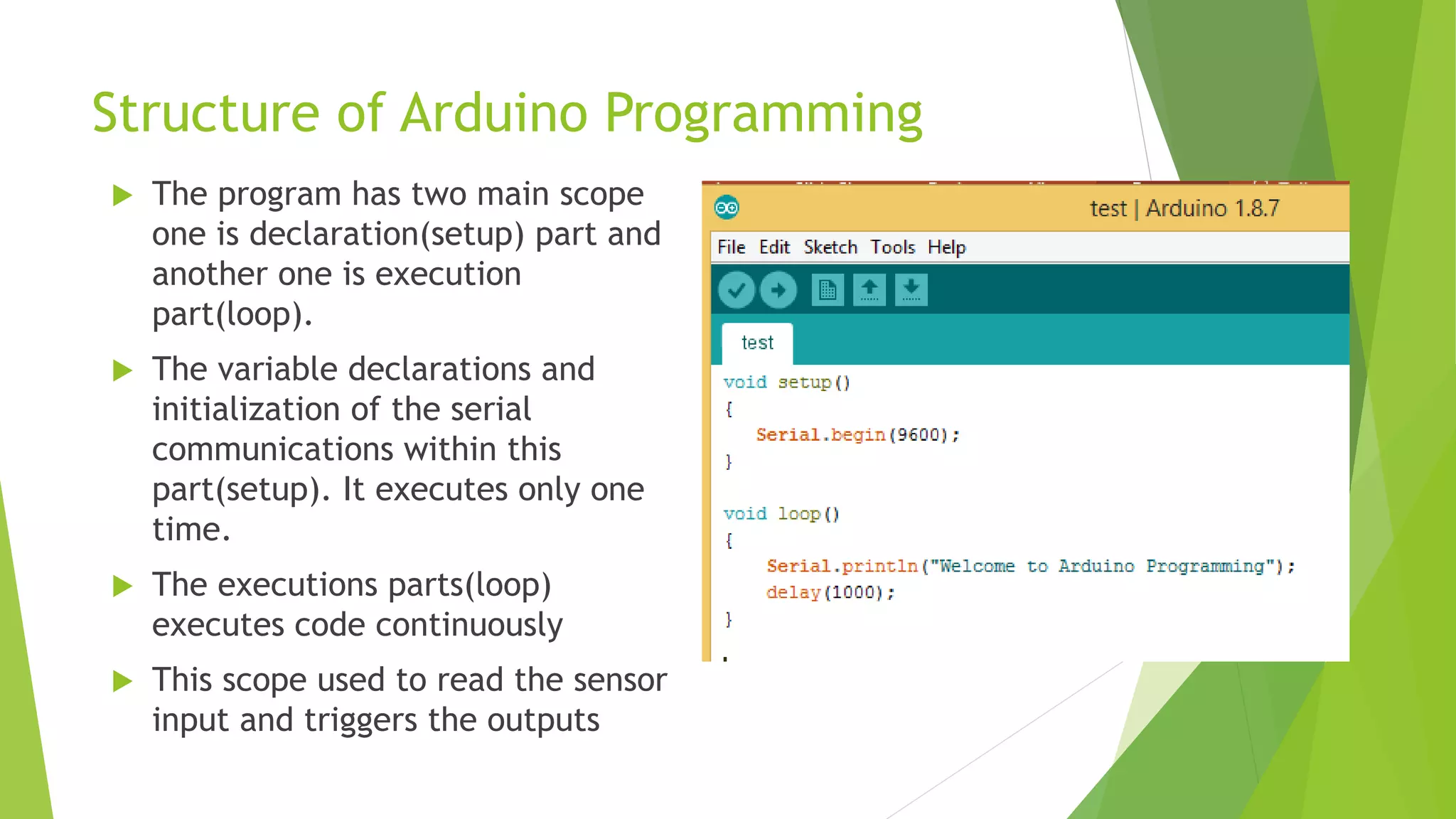
- The structure of Arduino programs with setup and loop functions. Setup runs once and loop runs continuously.
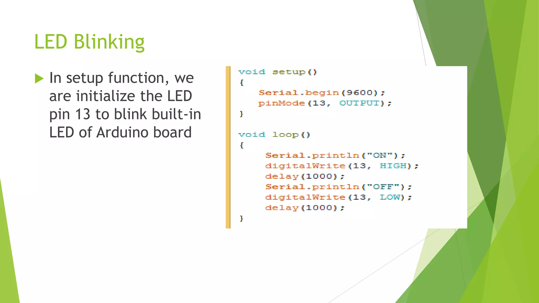
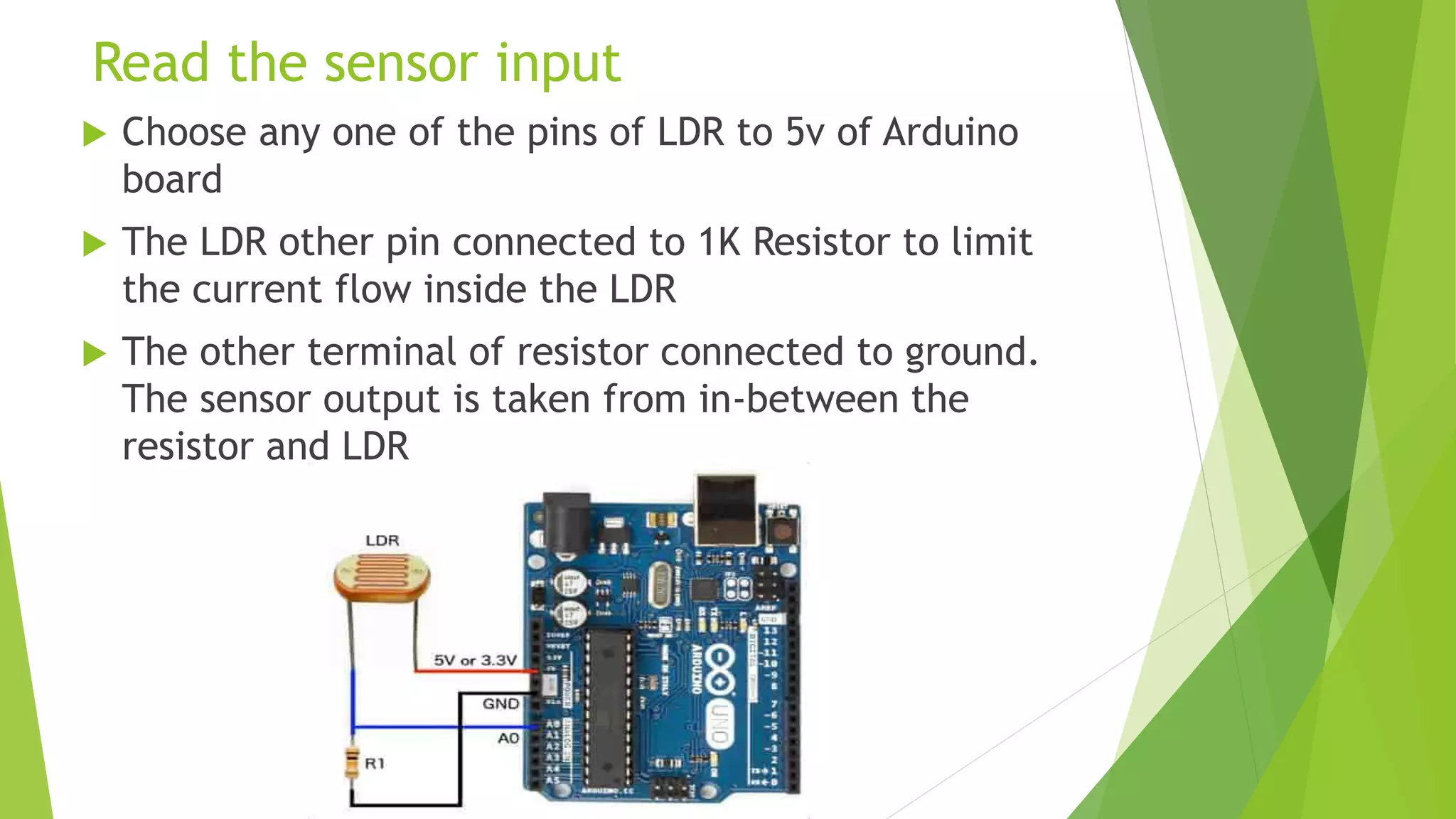
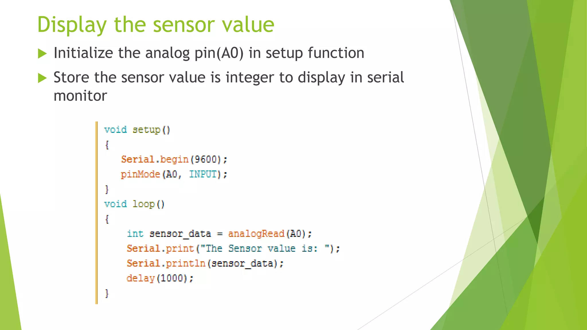
- Examples of blinking an LED on Arduino and reading light sensor input to display values.
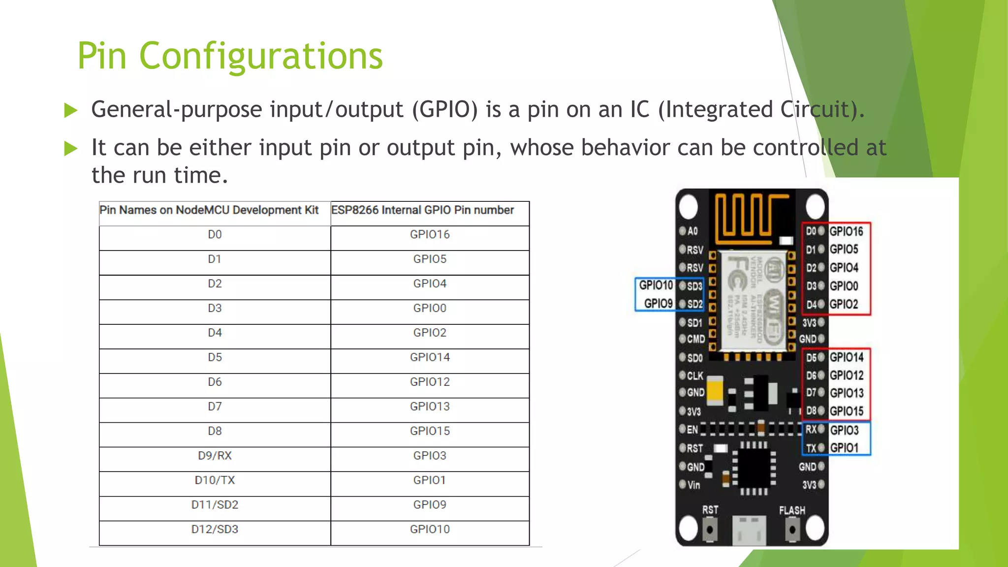
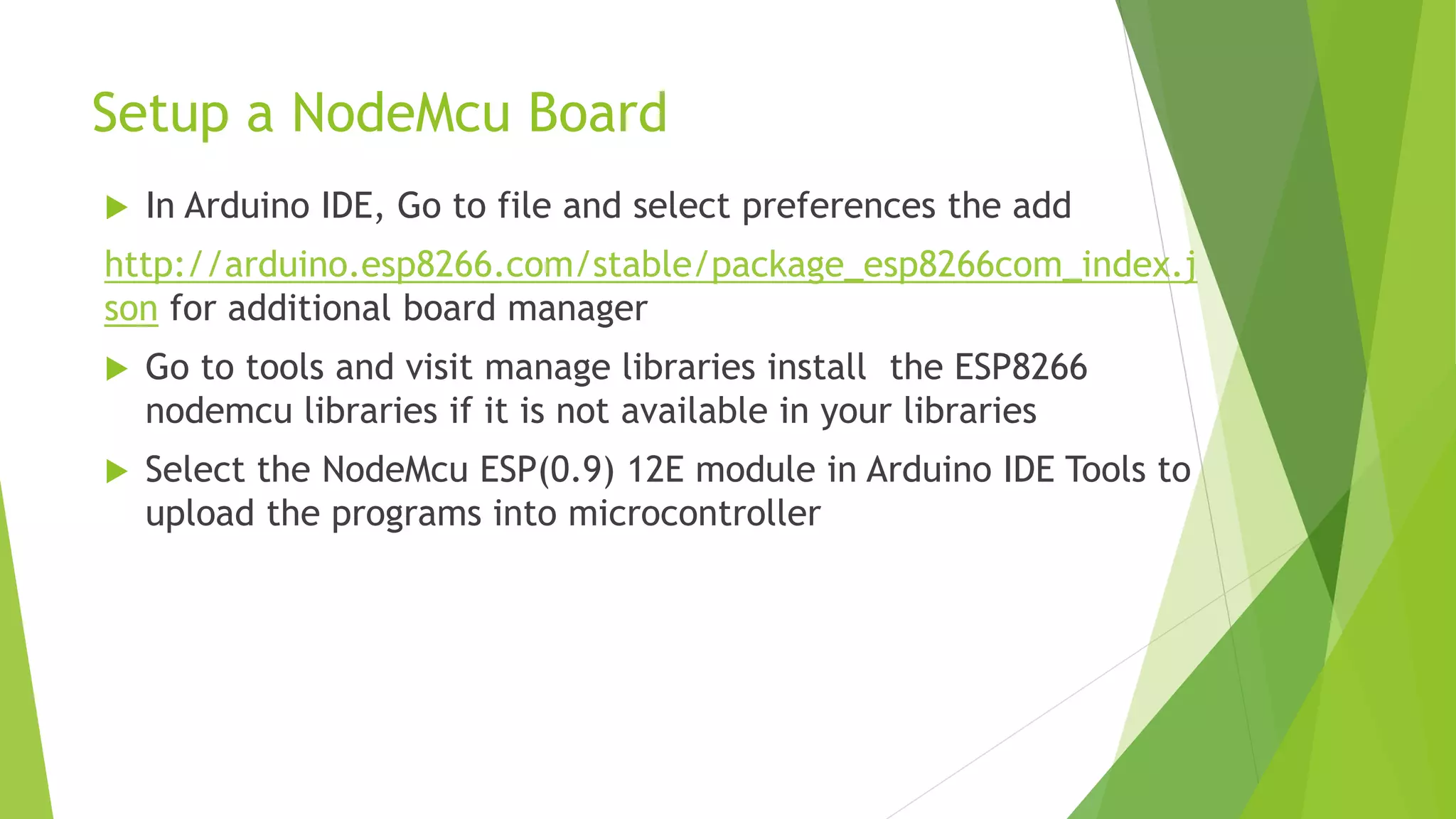
- Pin configurations on NodeMCU and setting it up in Arduino IDE.
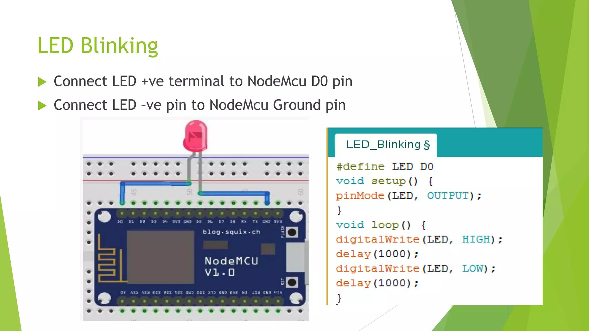
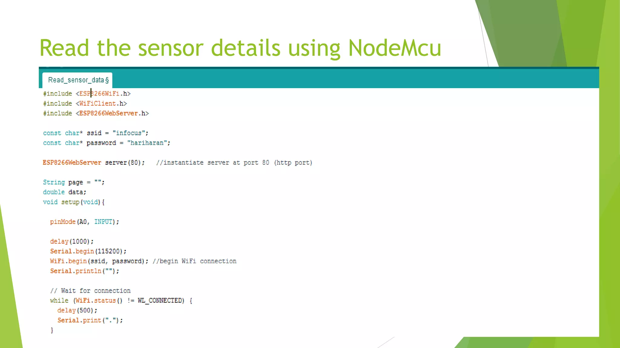
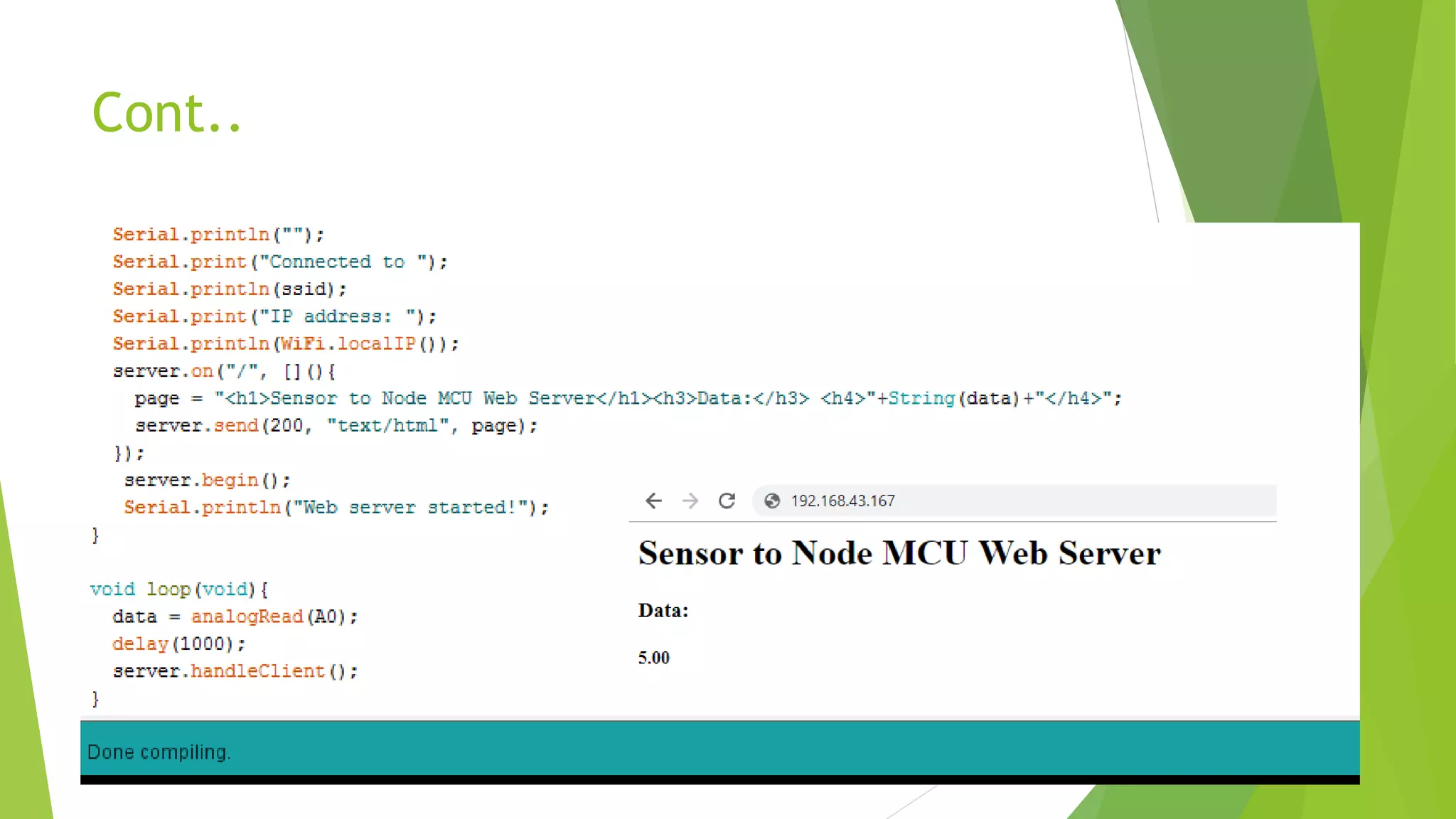
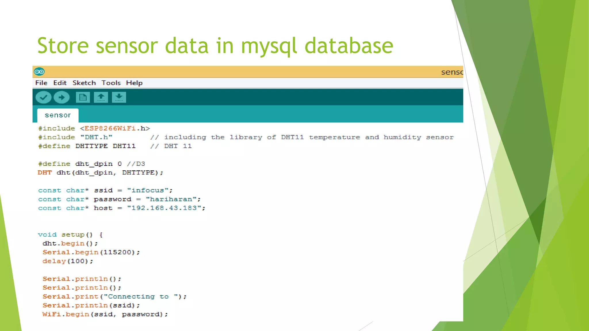
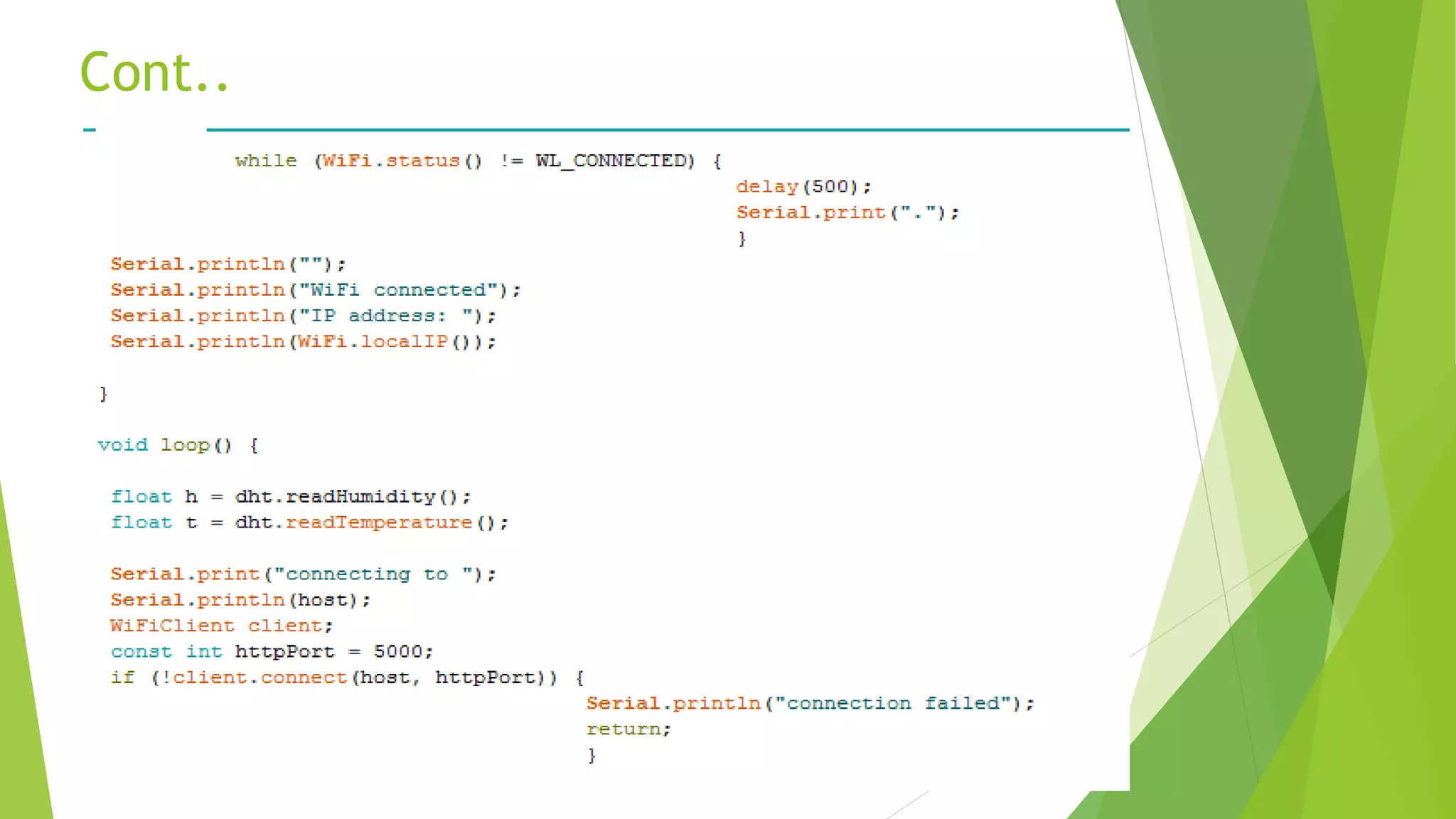
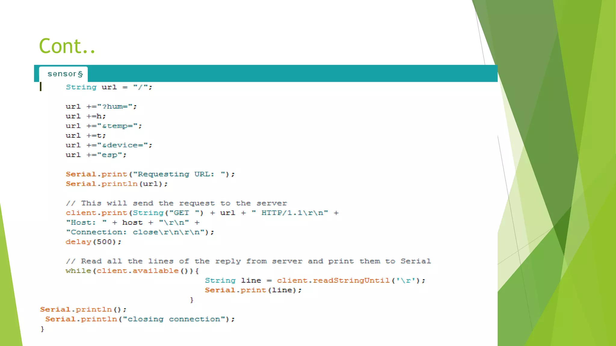
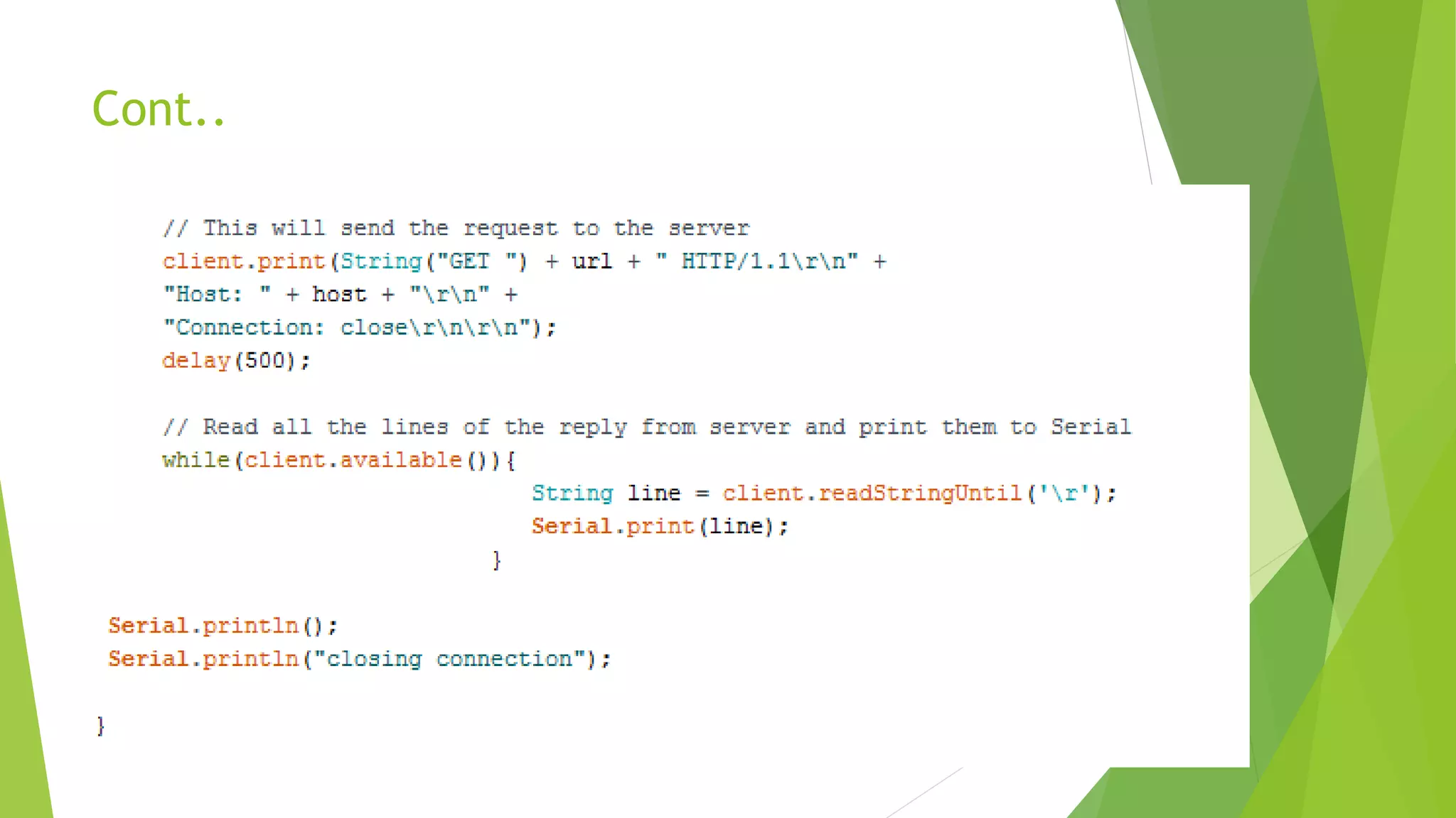
- Examples of blinking an LED and reading a sensor with NodeMCU and storing the sensor data in a MySQL database.
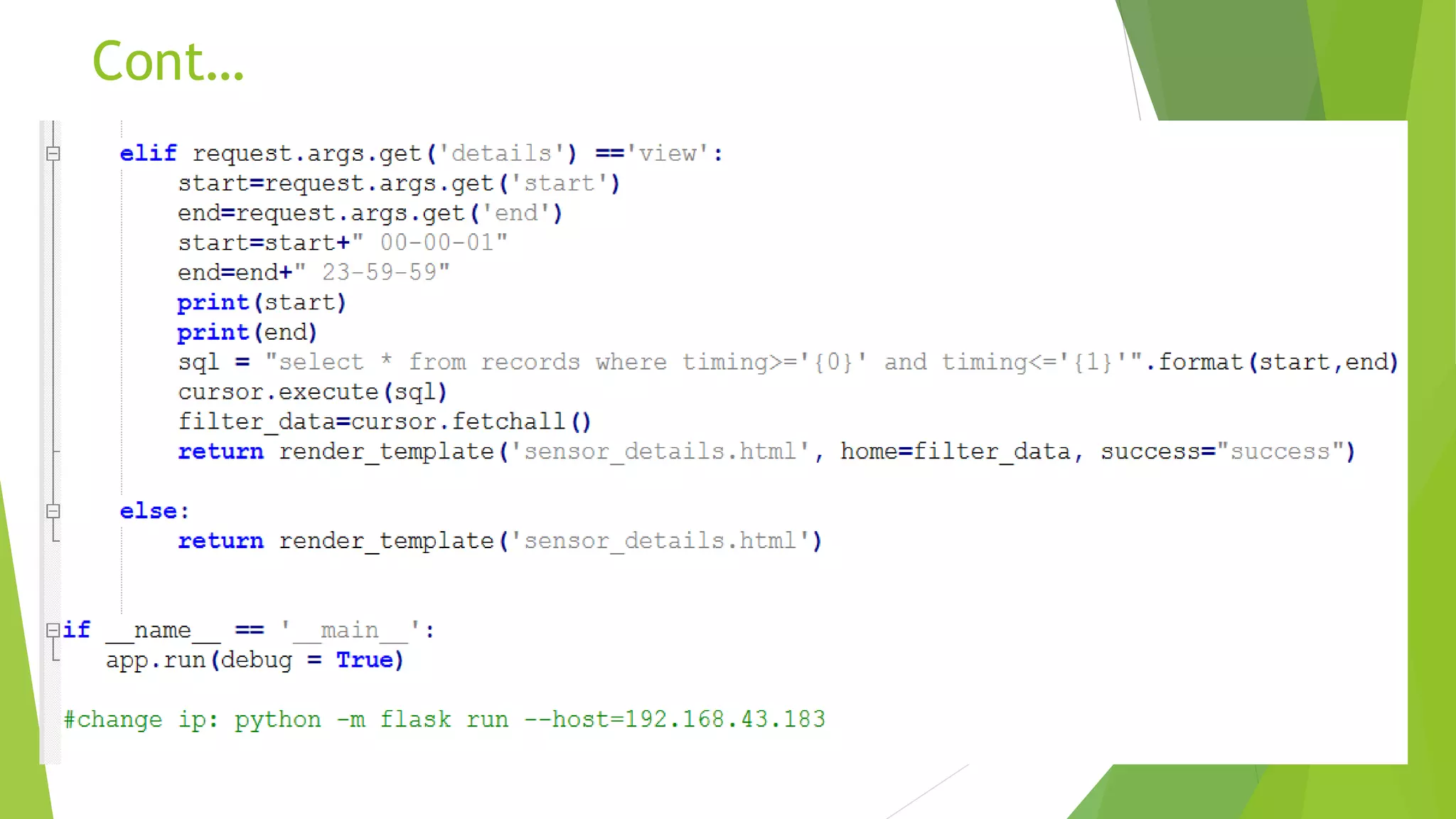
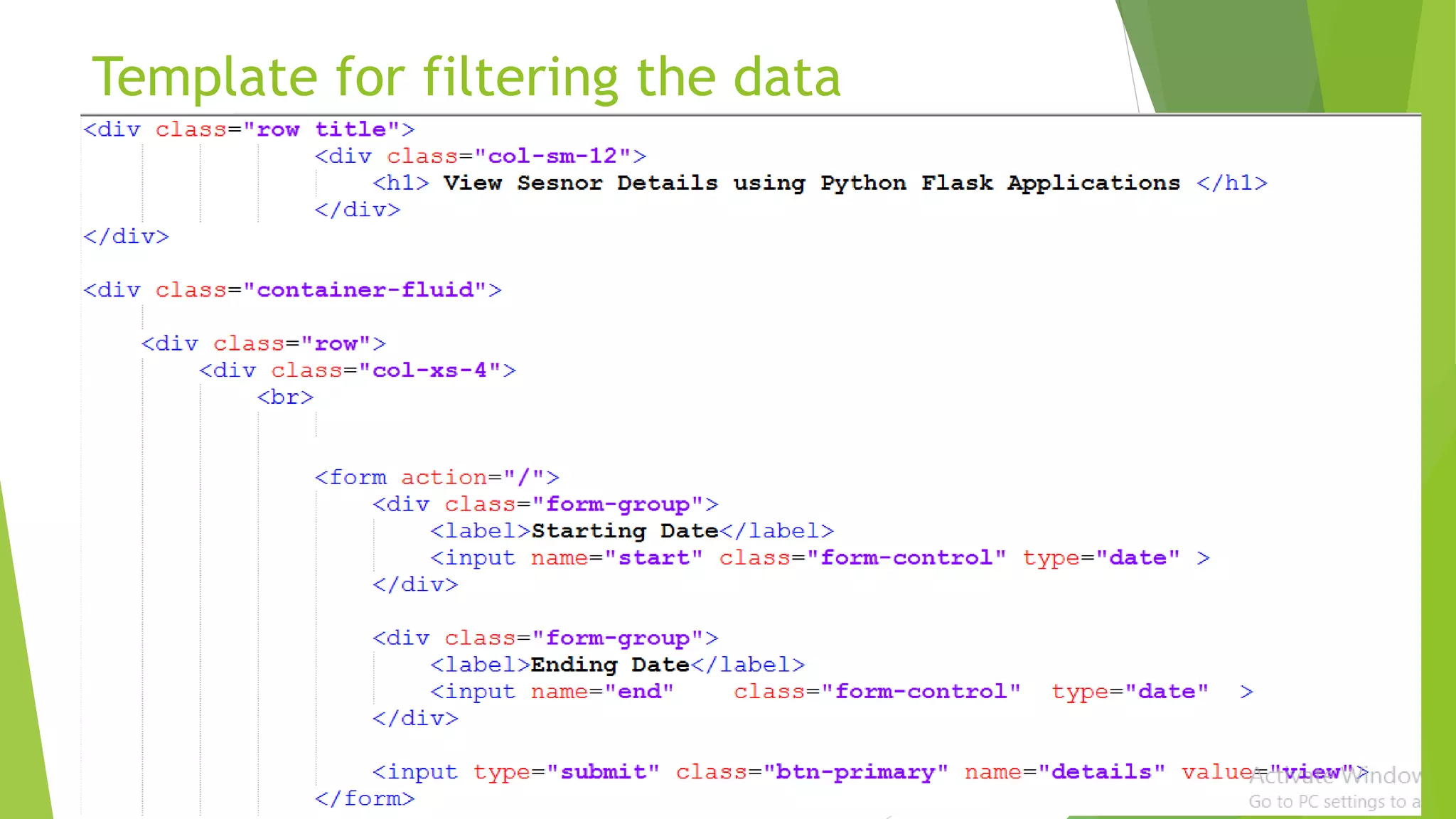
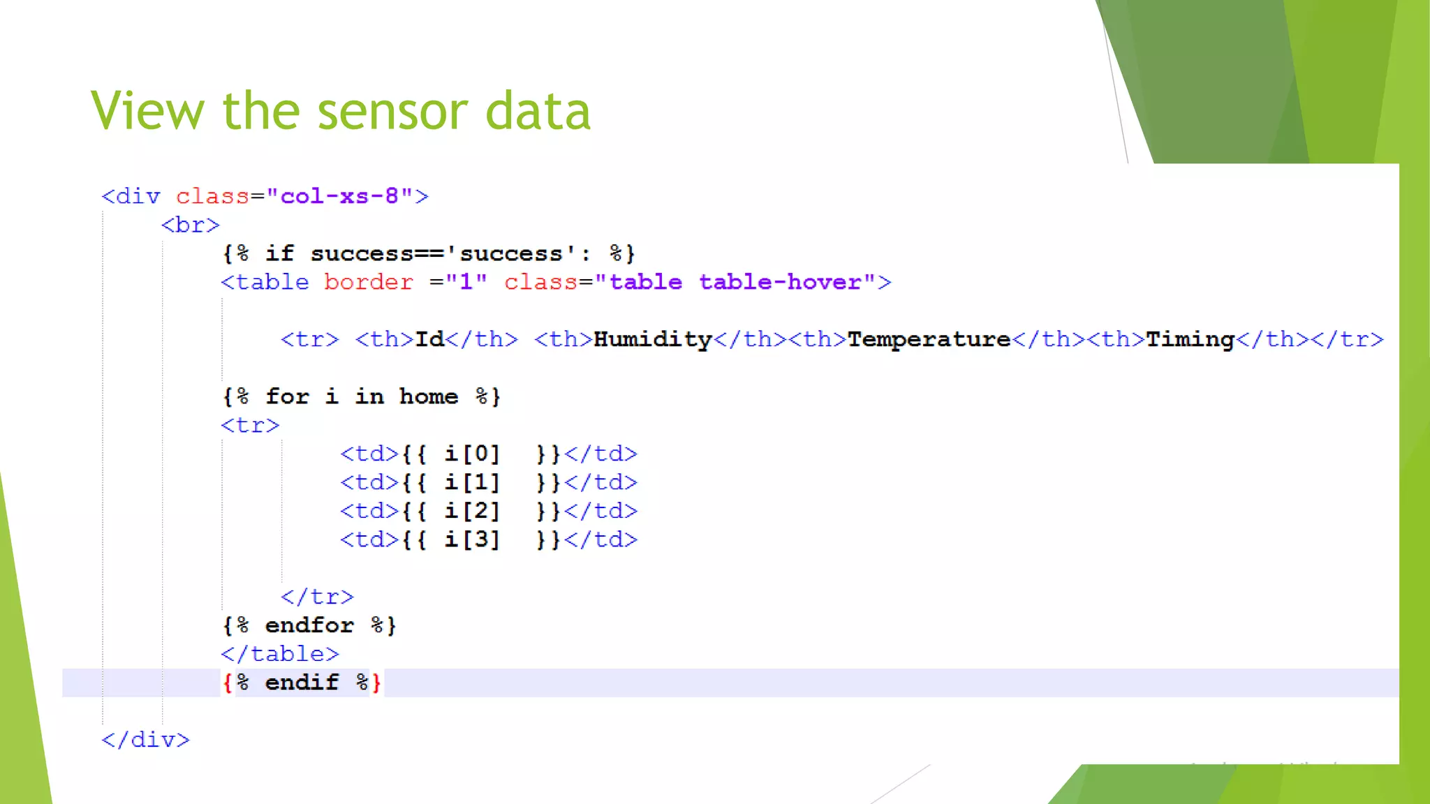
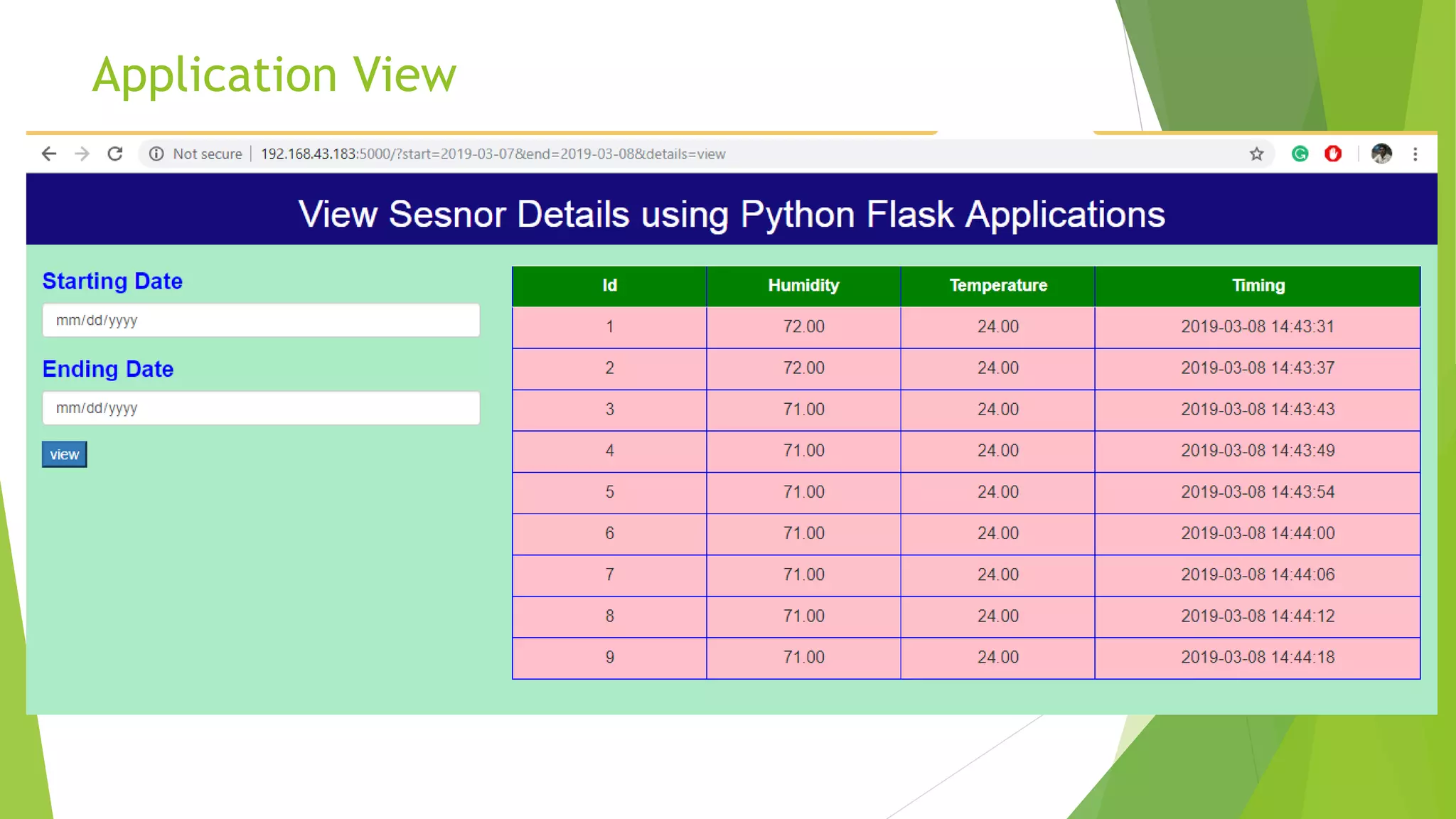
- Creating a Flask application to interface with the database and view the sensor data through templates.


![Introduction to ESP32 Programming [Road to RIoT 2017]](https://cdn.slidesharecdn.com/ss_thumbnails/roadtoriotsurabayagettingstartedesp32-170726155154-thumbnail.jpg?width=640&height=640&fit=bounds)