Download as PDF, PPTX

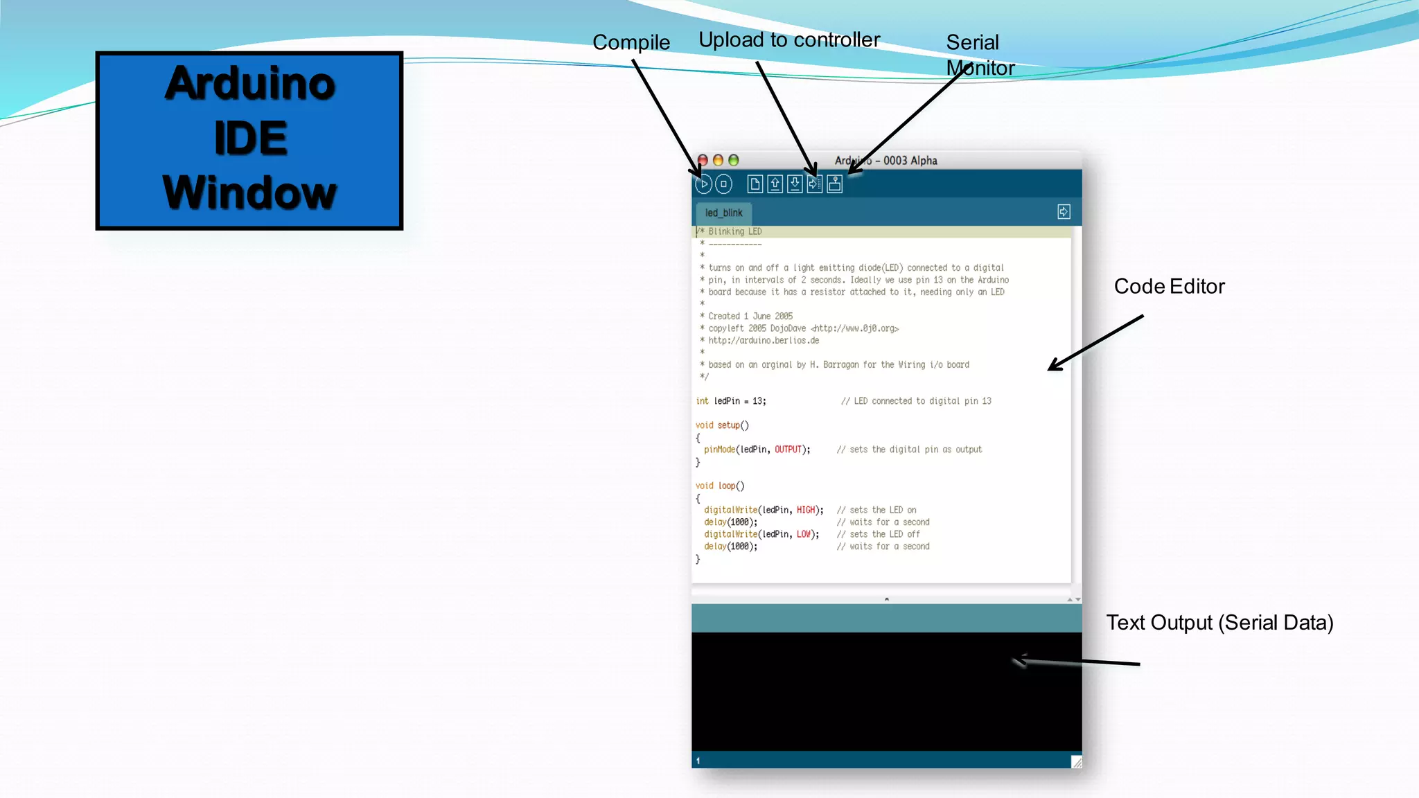
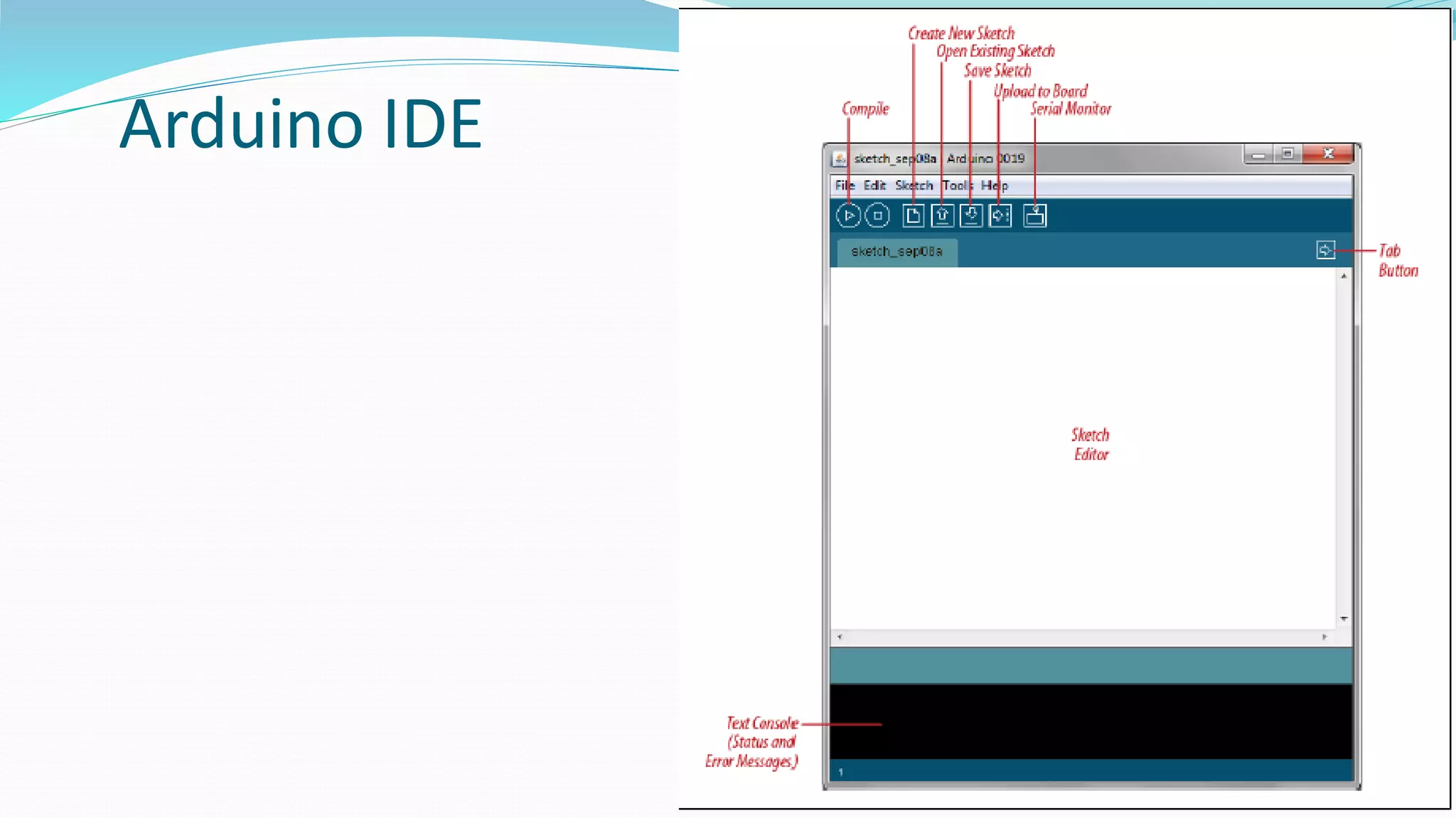

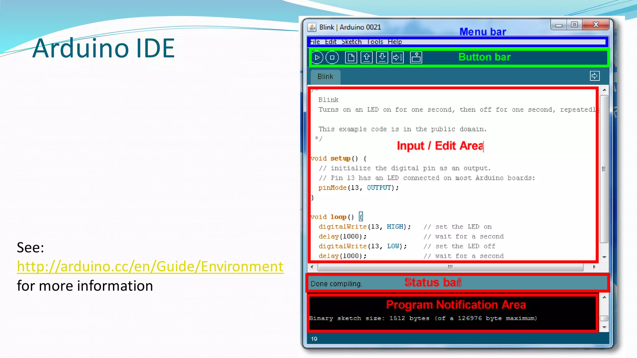
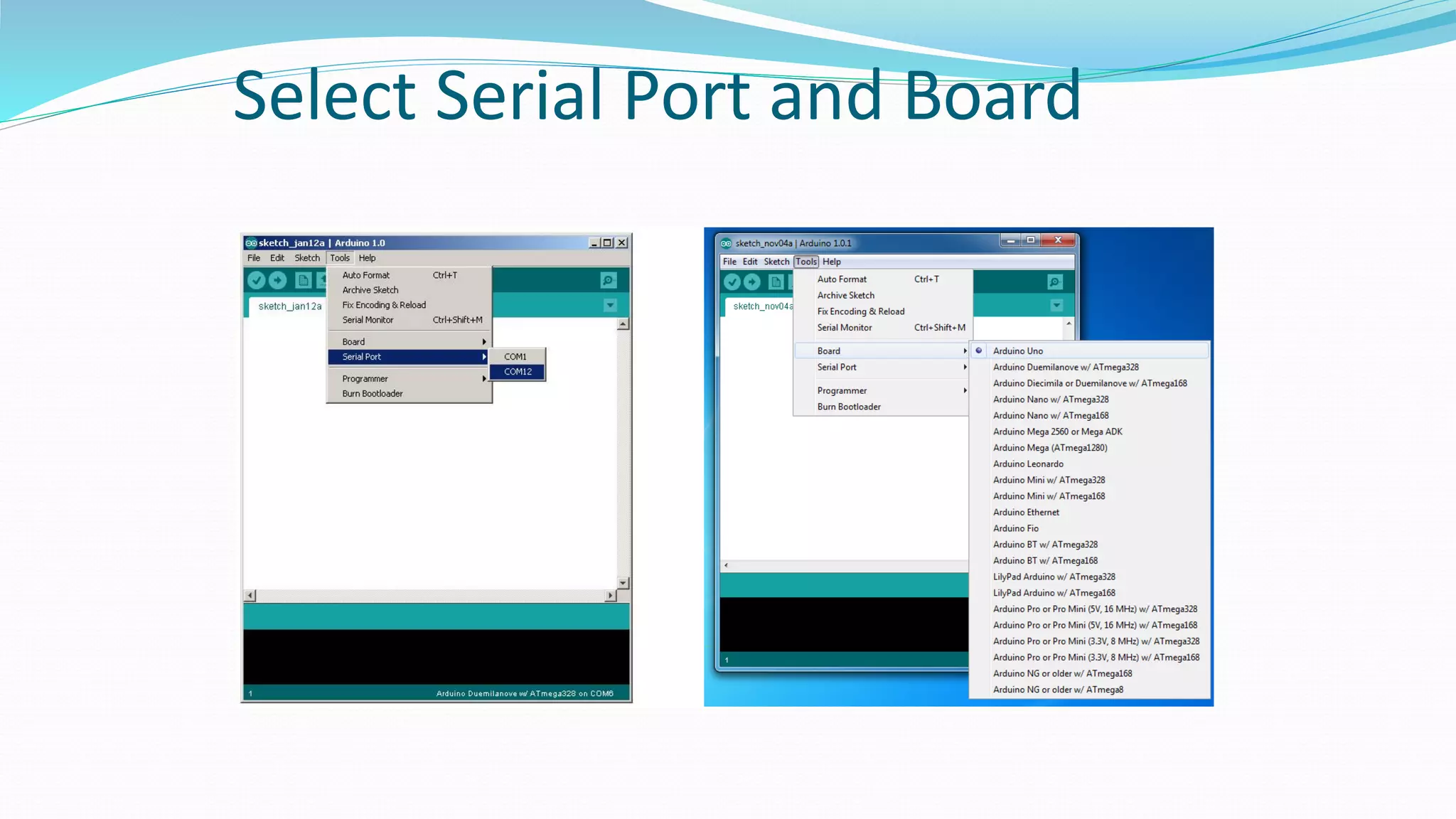
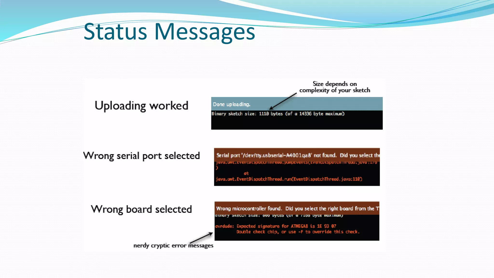
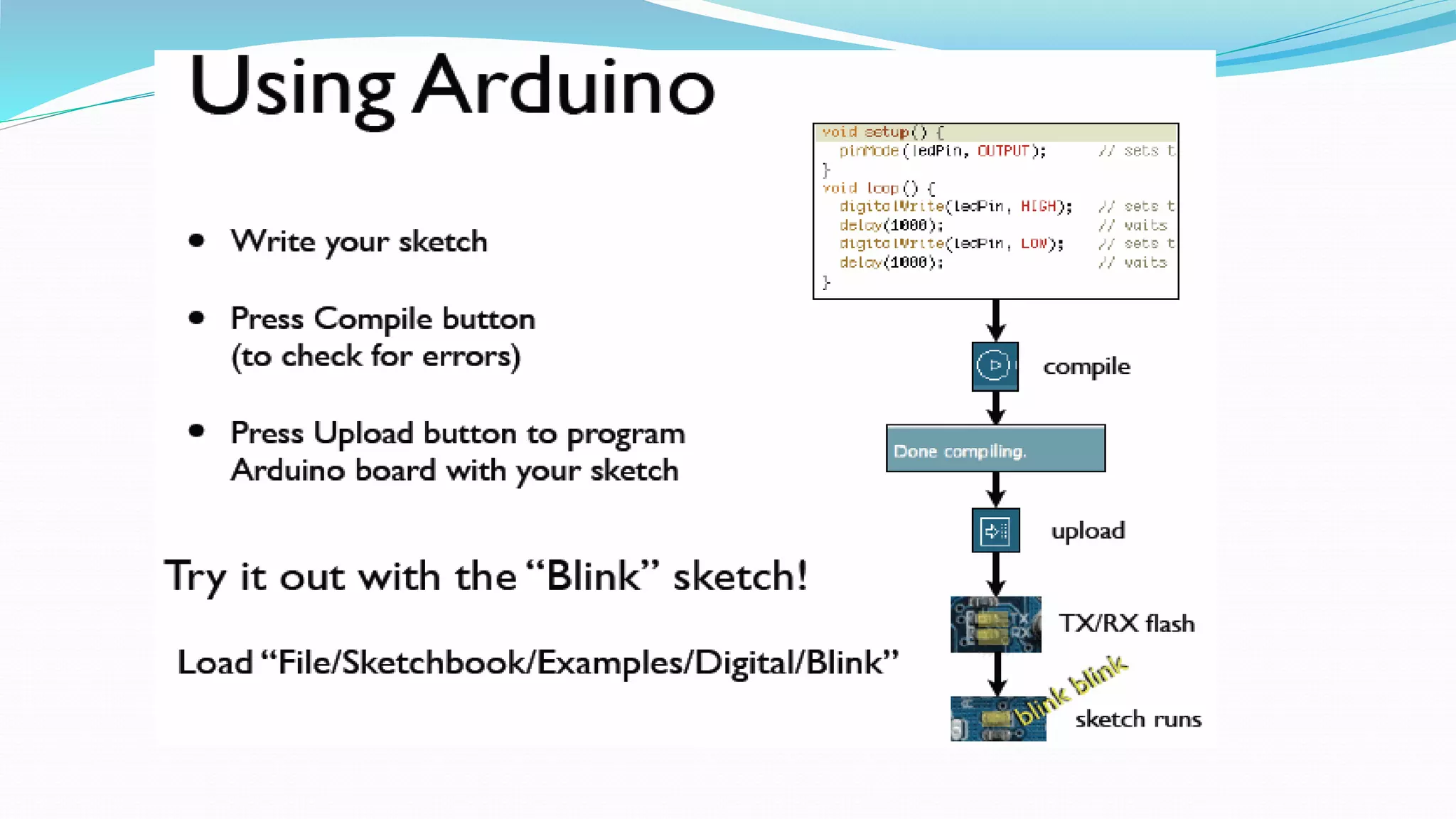

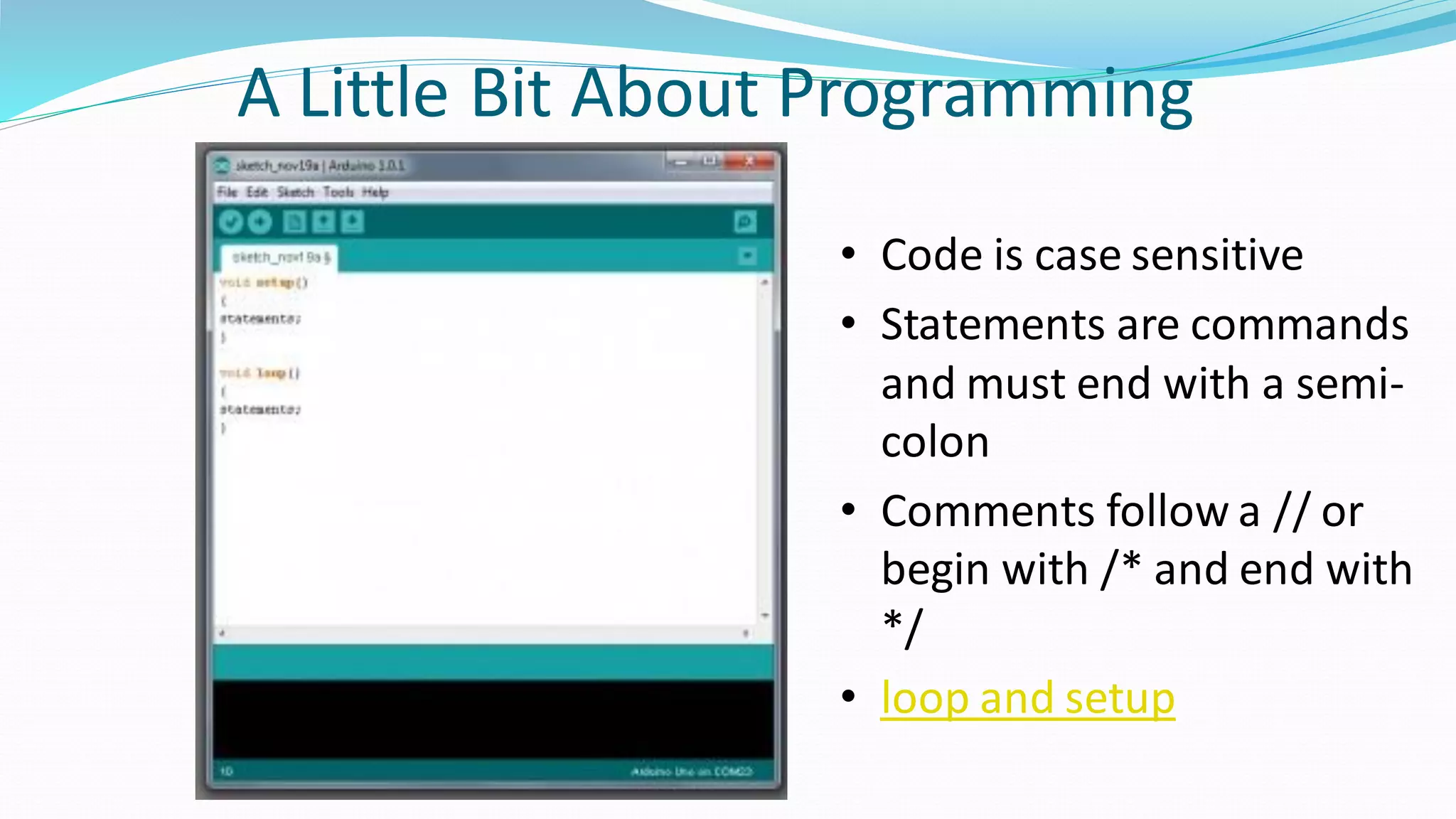
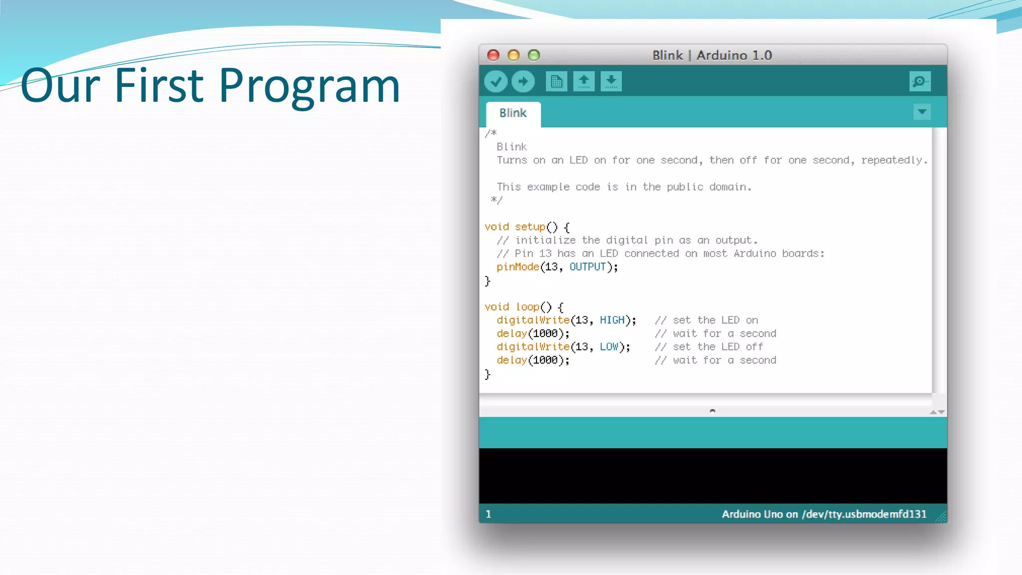


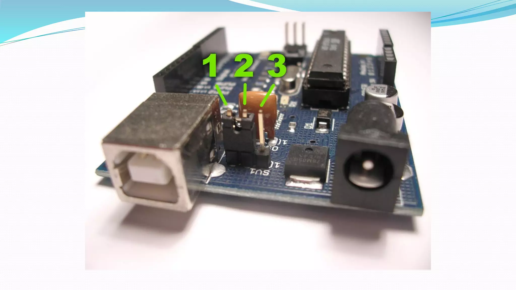
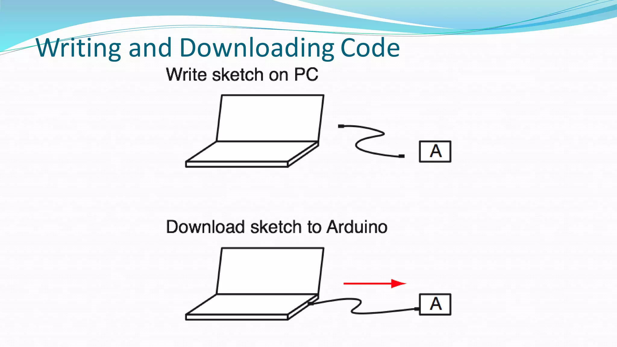
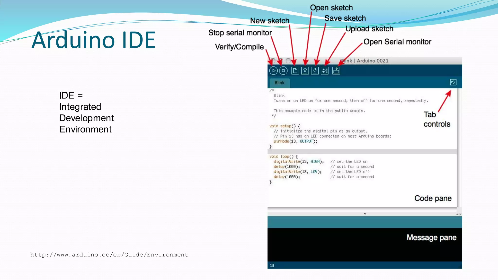

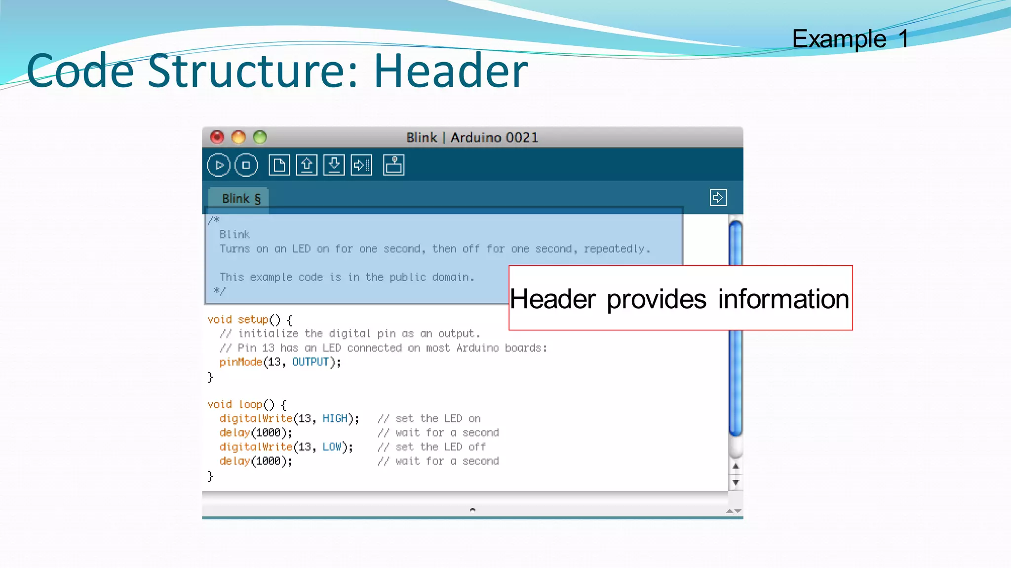
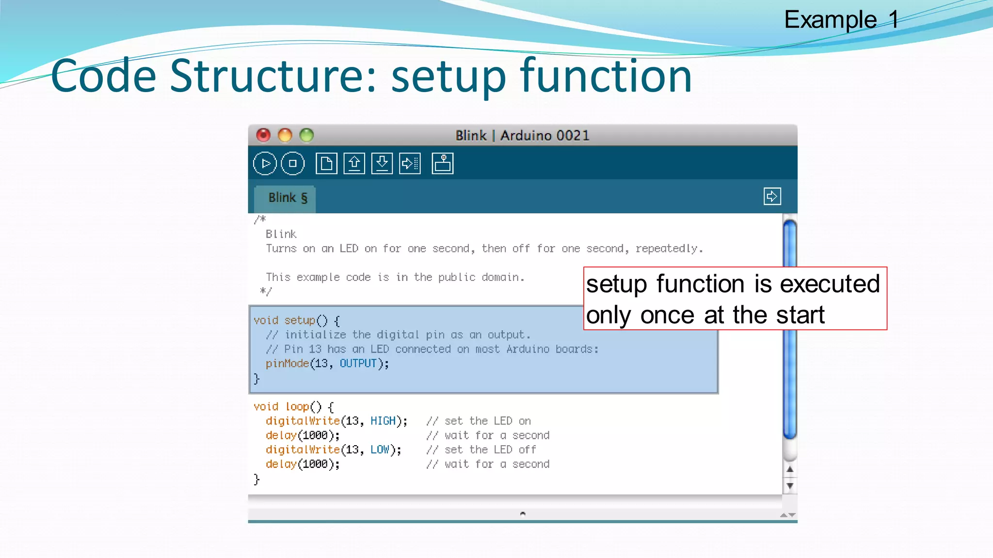
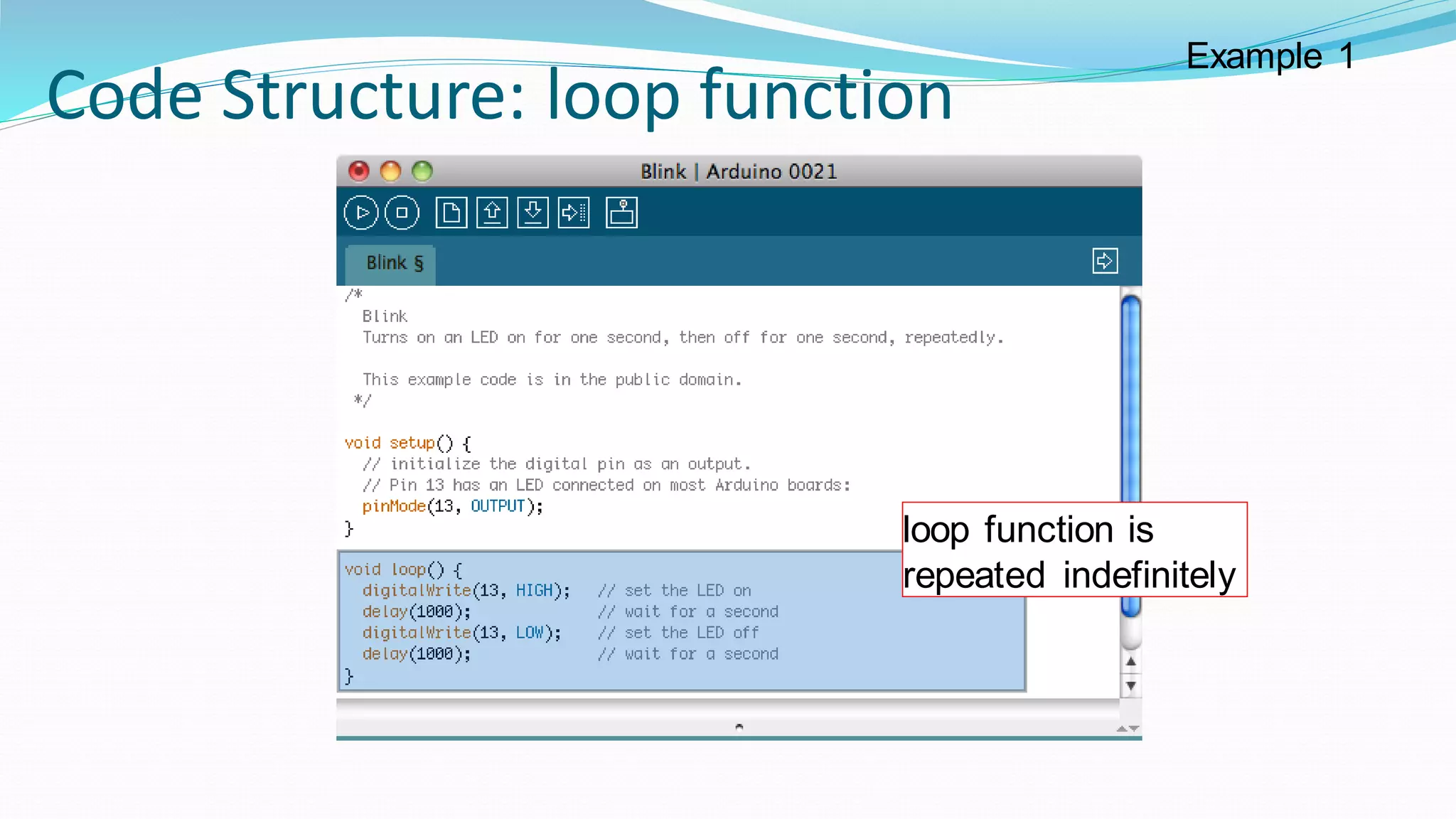
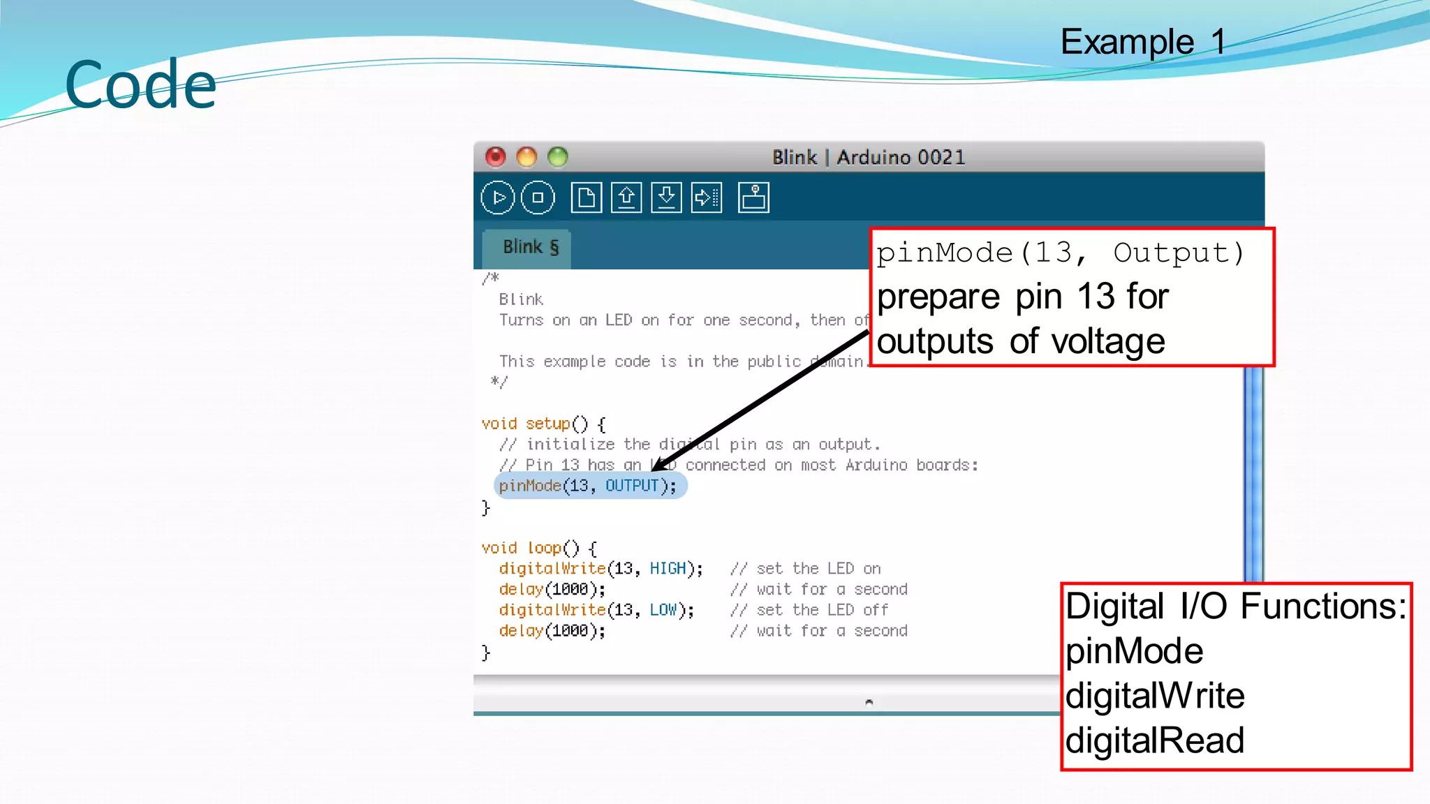
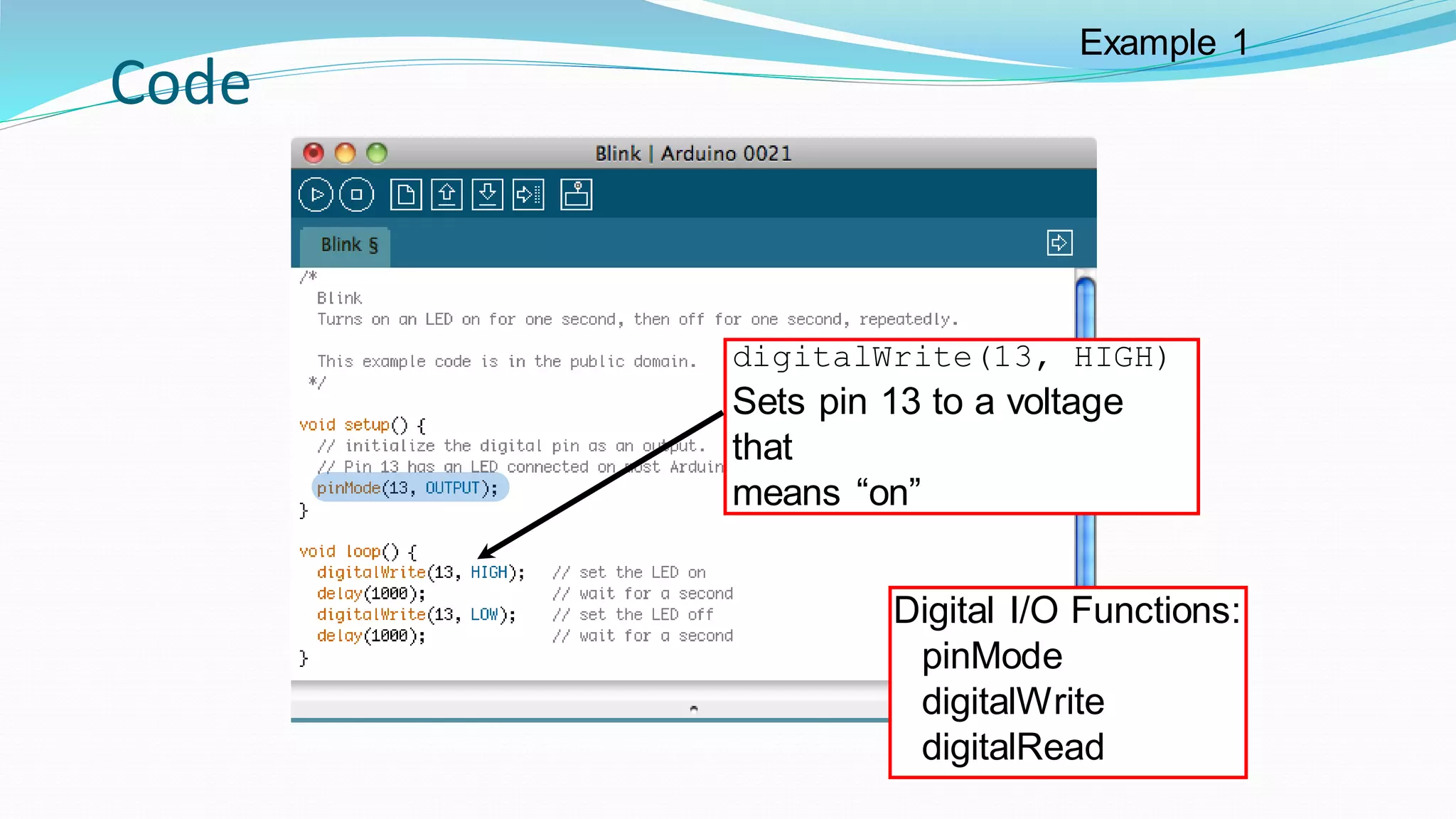
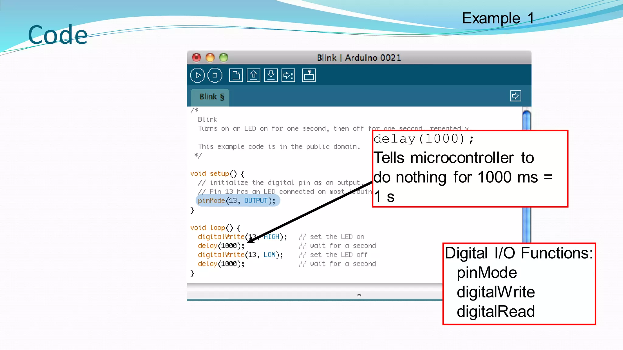
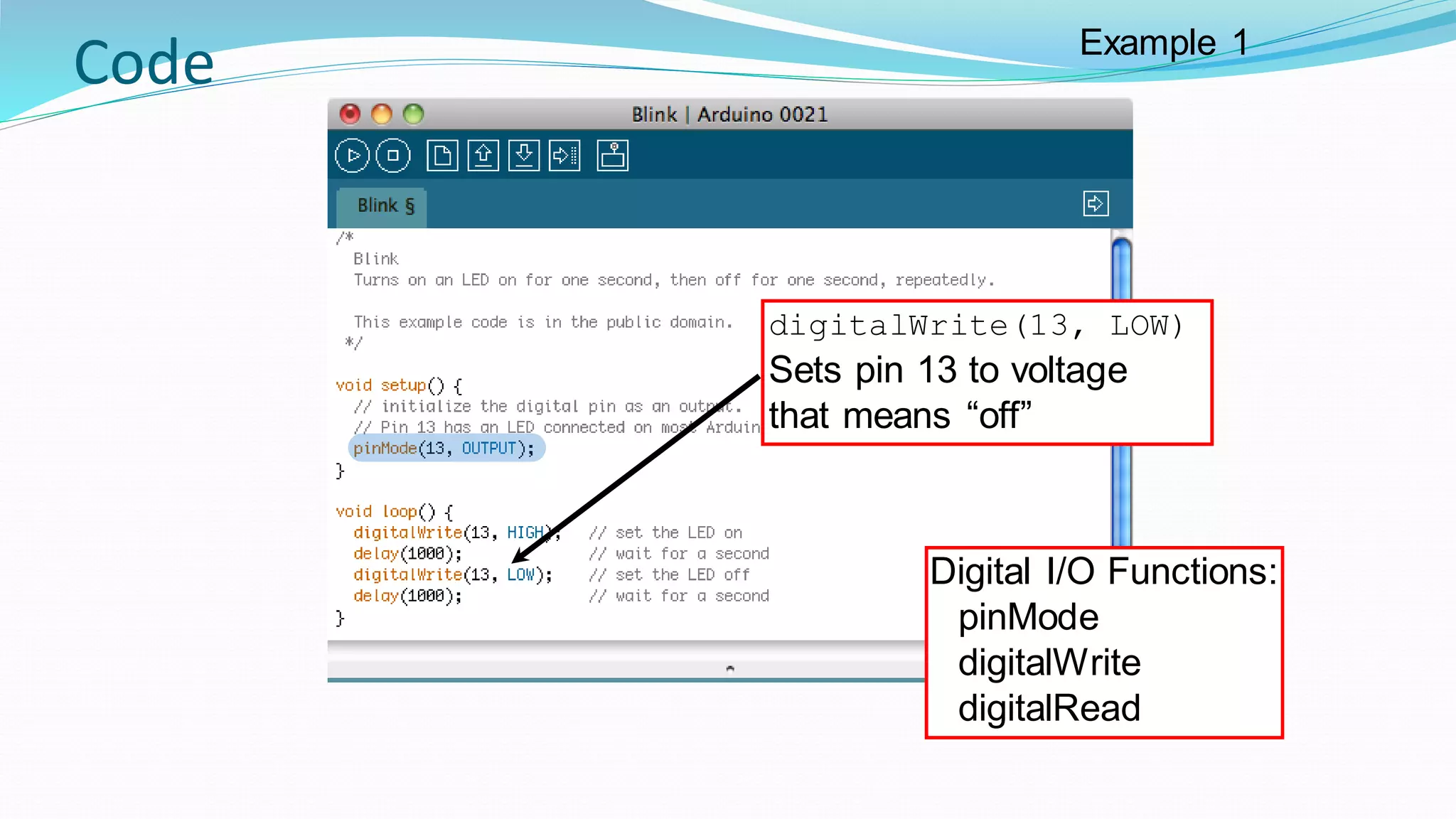


The document provides an overview of using the Arduino IDE to program an Arduino board. It discusses connecting an Arduino board to the computer, selecting the correct serial port and board settings in the IDE, and uploading a basic "Blink" program to flash an LED. The basics of Arduino code structure and common functions like pinMode, digitalWrite, and delay are also explained at a high level.