The document provides an introduction and overview of Arduino boards and programming. It discusses:
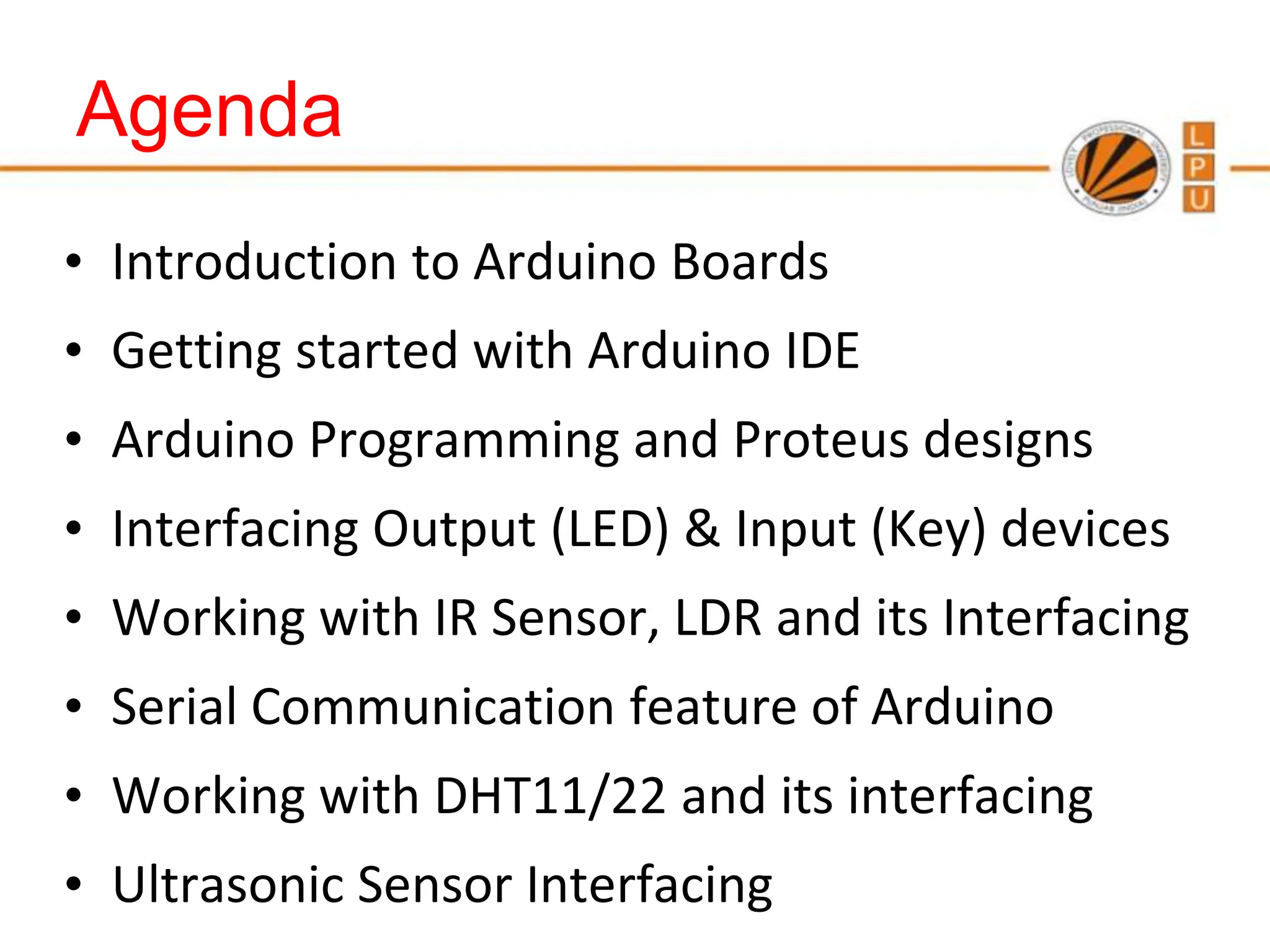
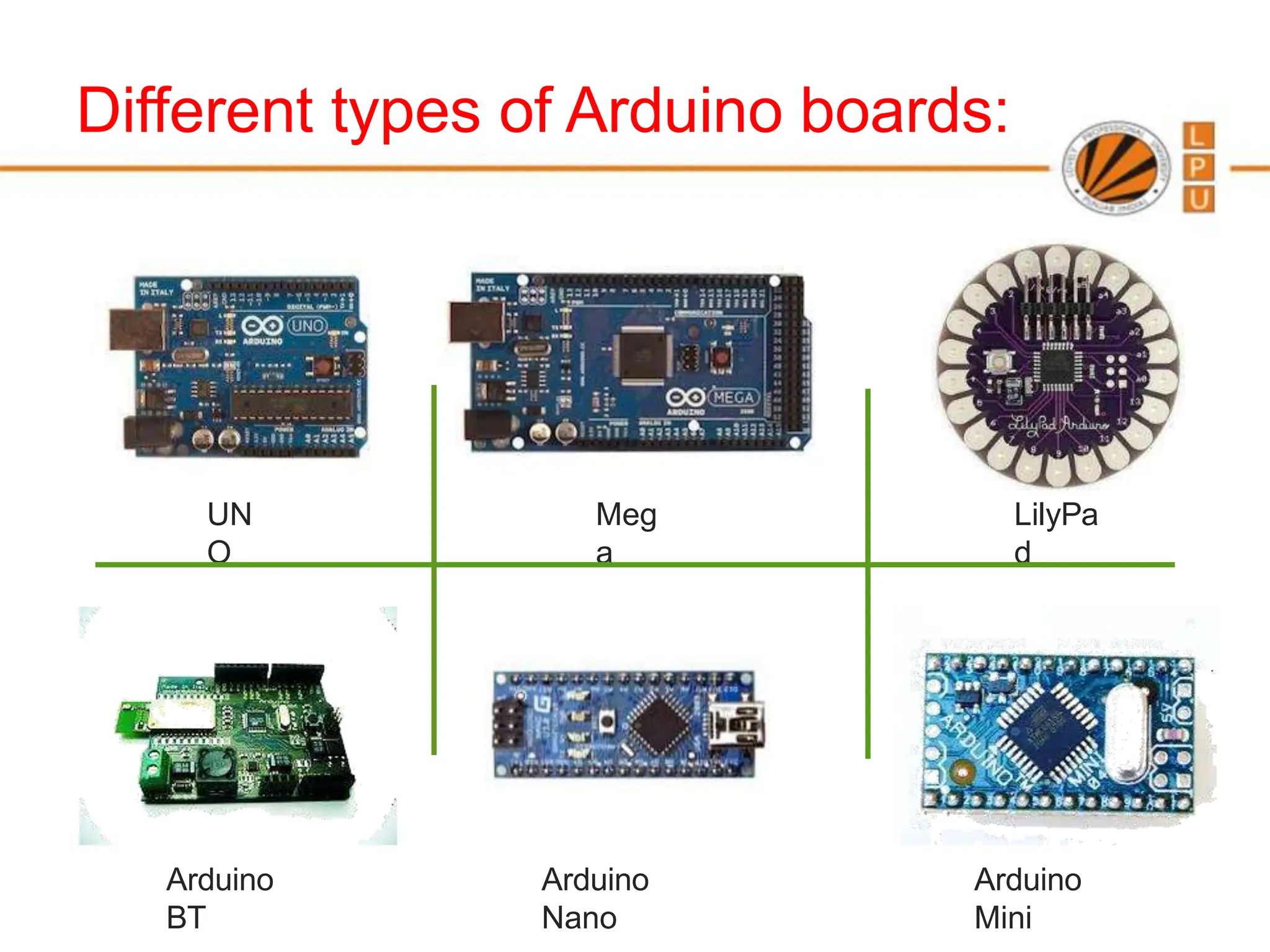
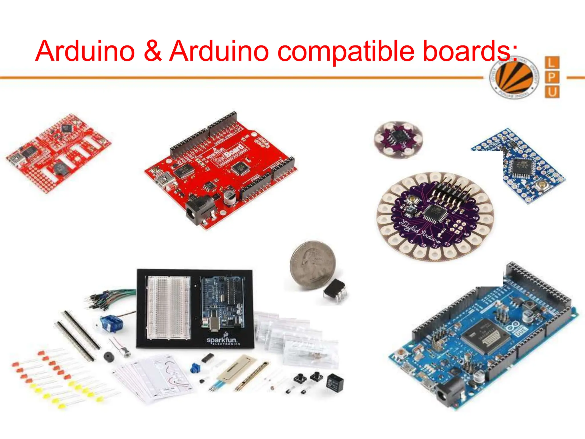
- The different types of Arduino boards available.
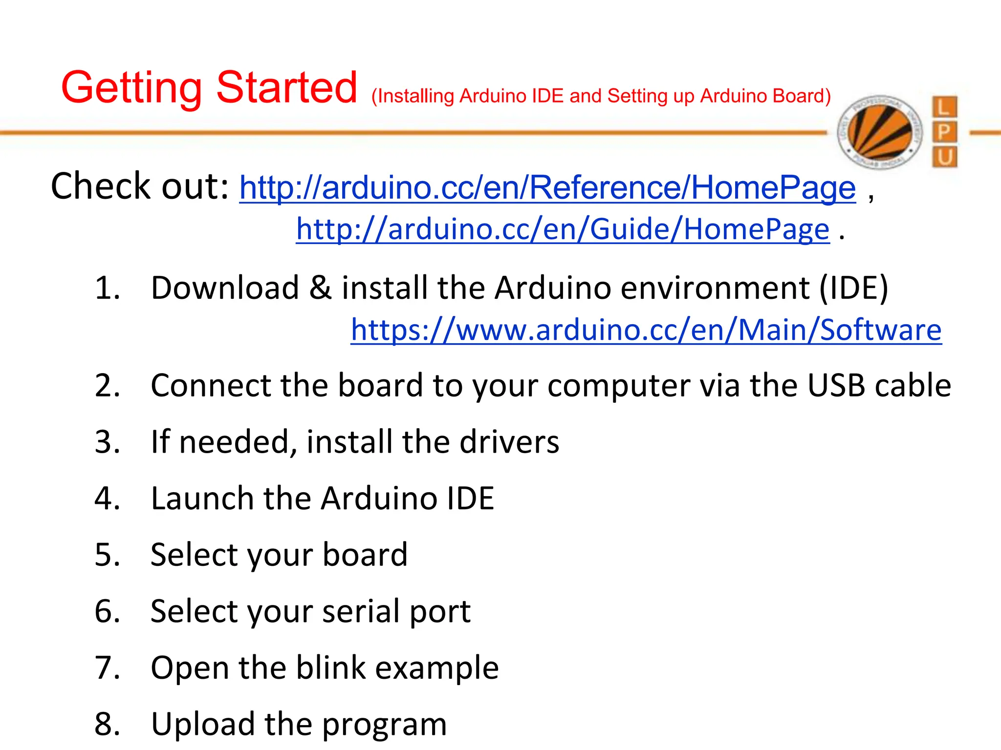
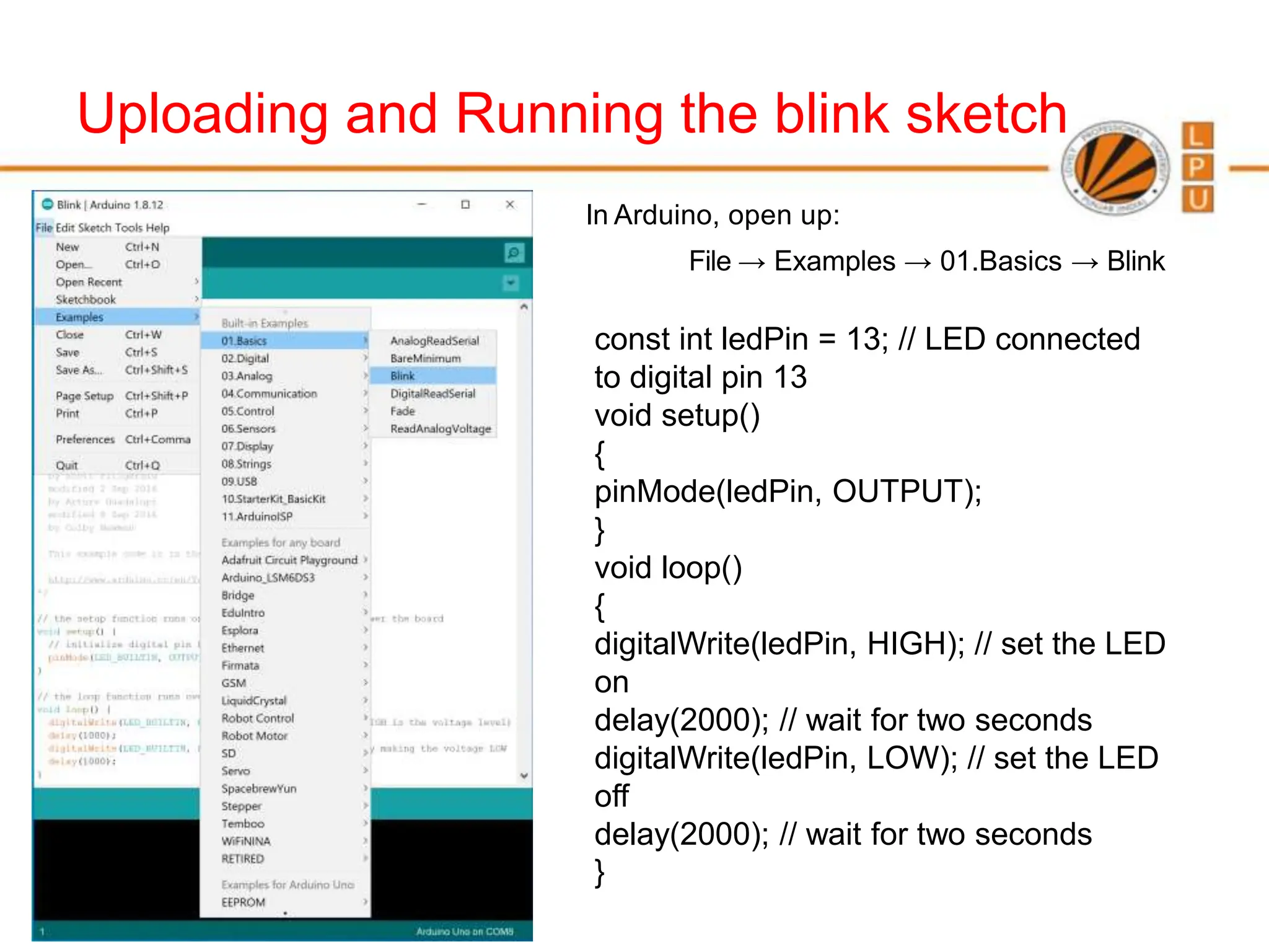
- How to get started with the Arduino IDE and programming Arduino boards.
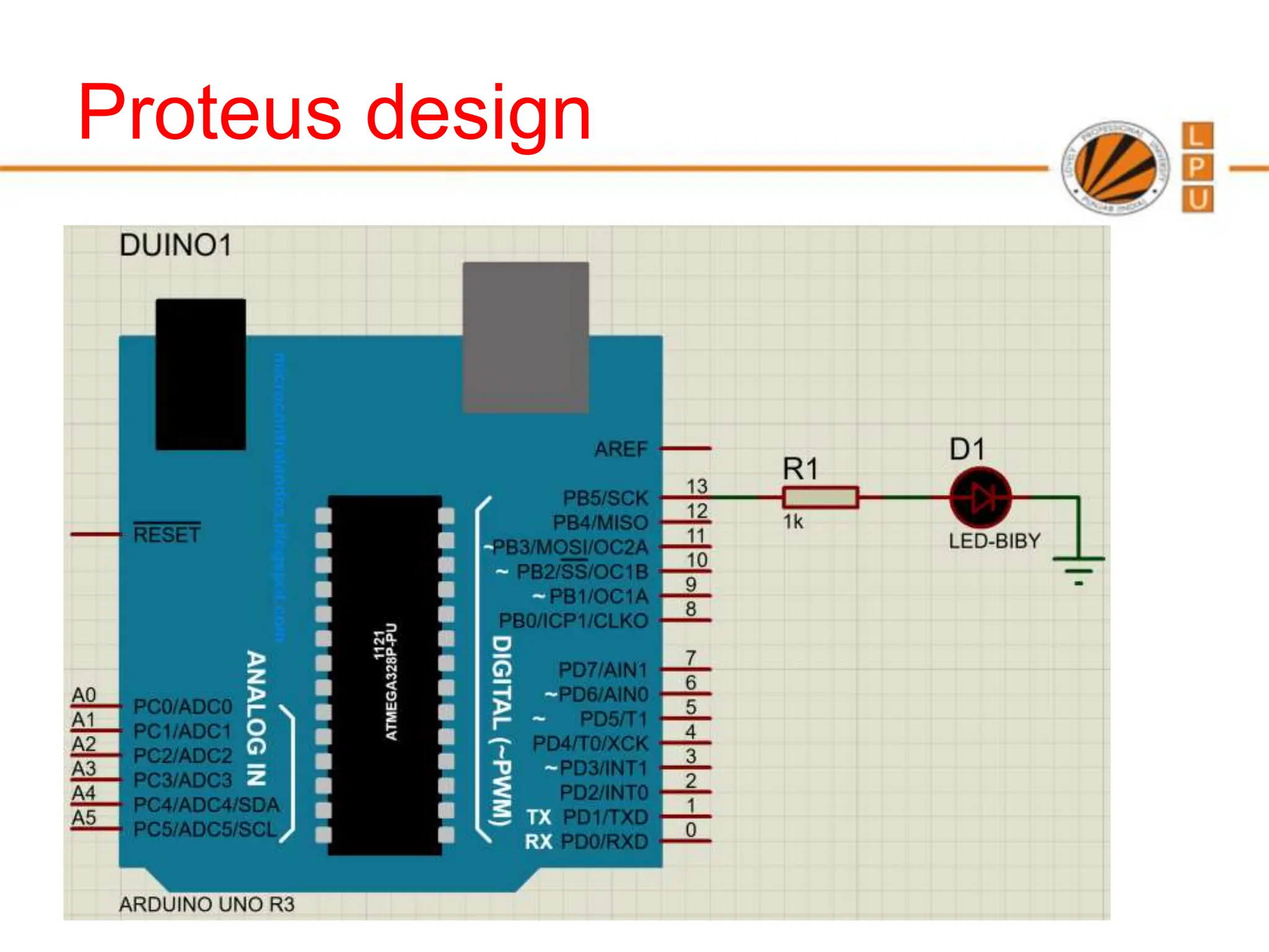
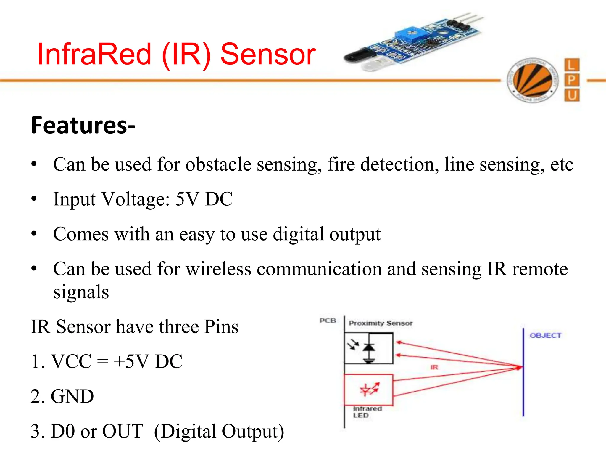
- Examples of common sensors and actuators that can be connected to Arduino boards like LEDs, buttons, temperature sensors.
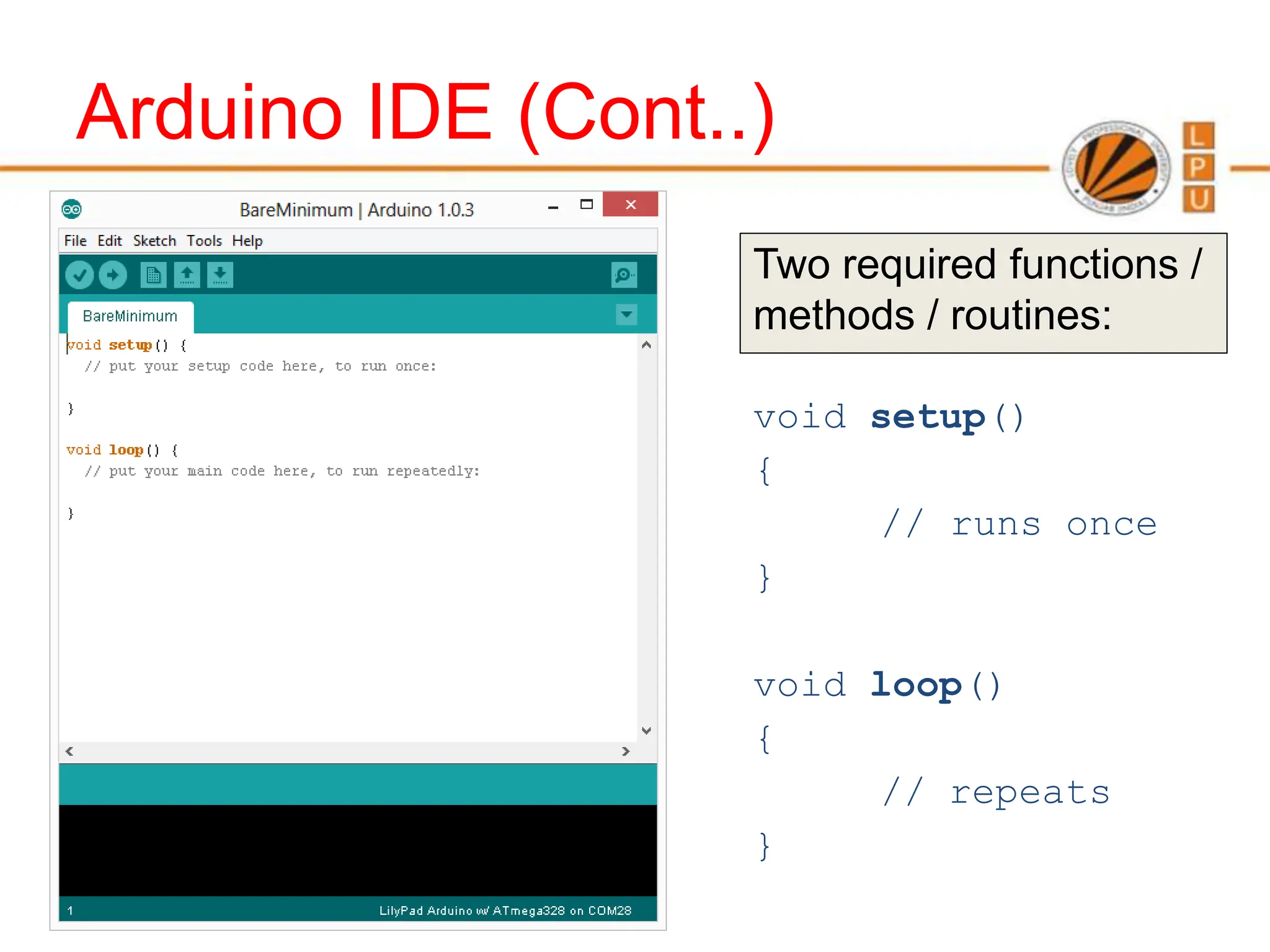
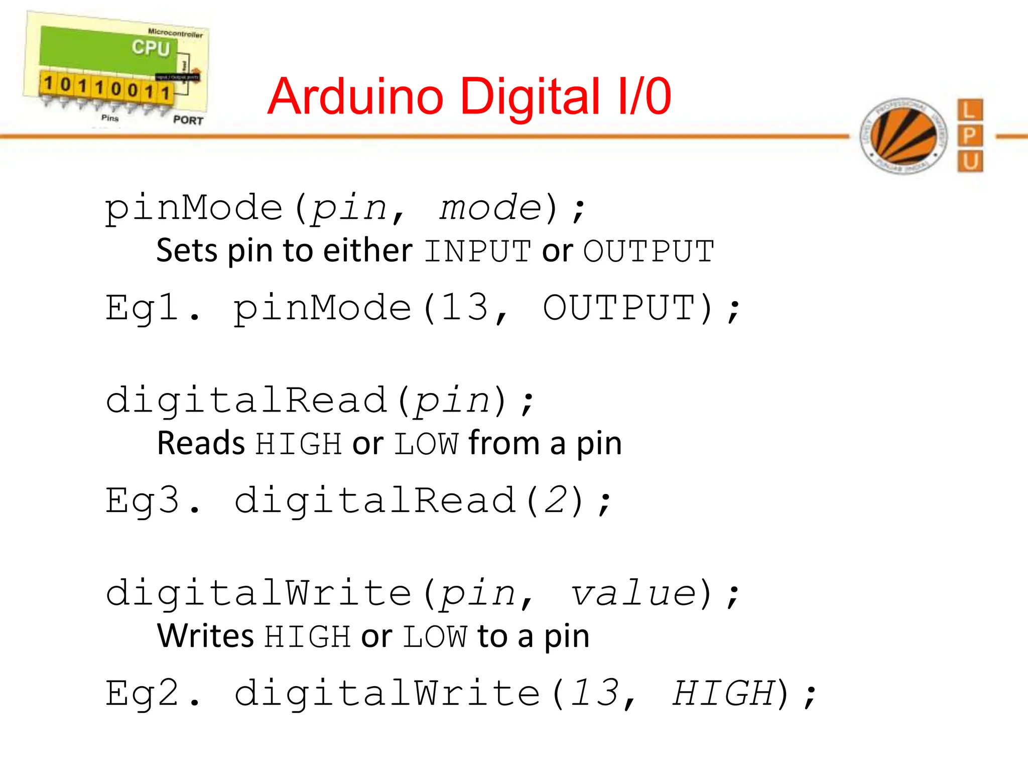
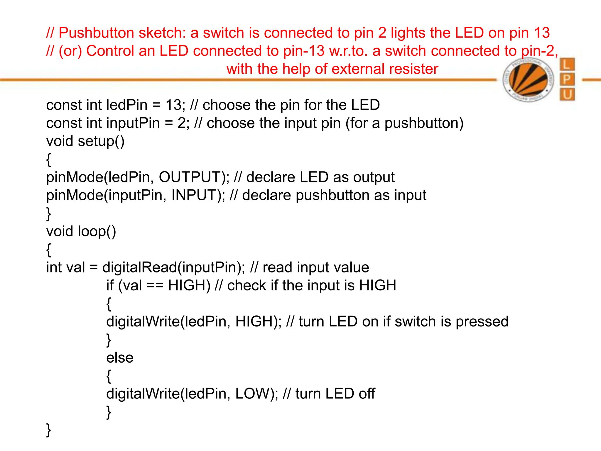
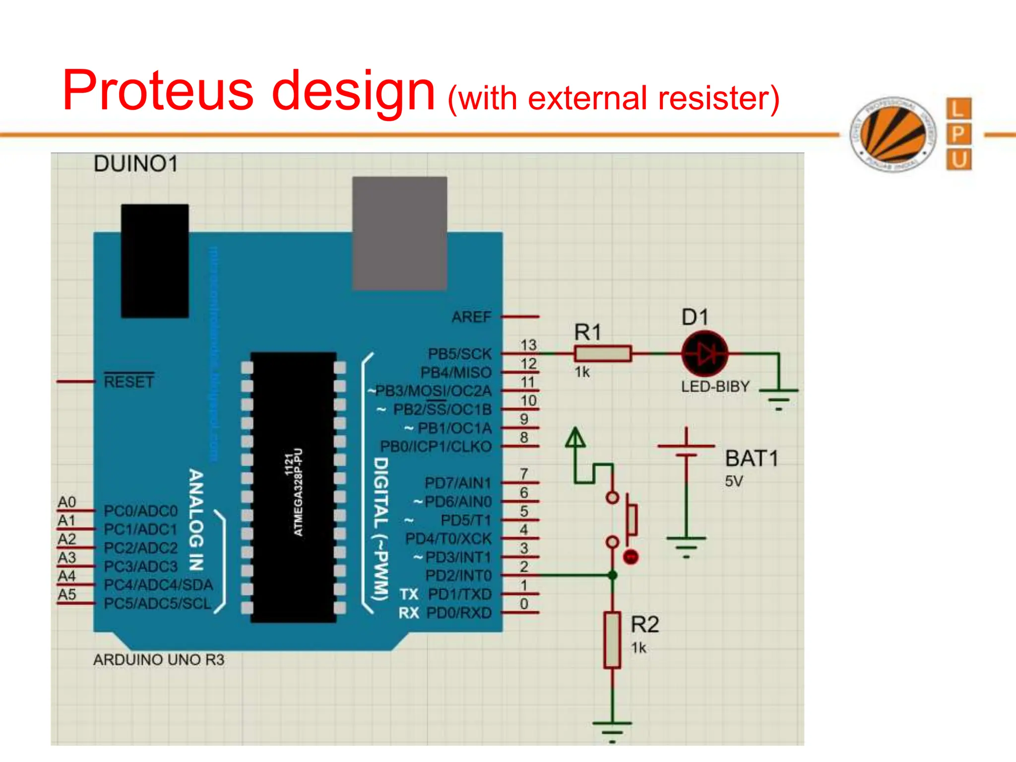
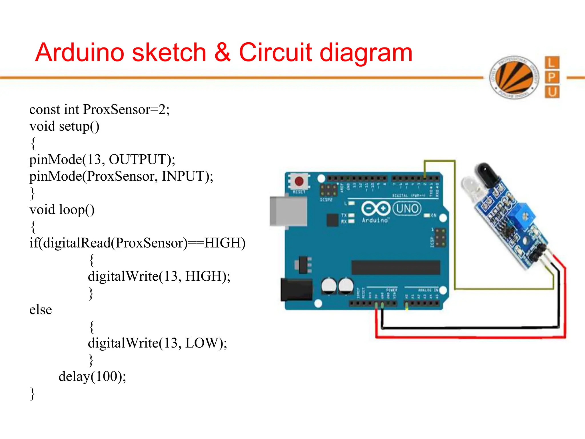
- The basic structure of Arduino programs including setup(), loop(), and common functions like digitalRead(), digitalWrite(), and pinMode().


![Statements and operators:
Statement represents a command, it ends with ;
Eg: int x; x=13;
Operators are symbols that used to
indicate a specific function:
Math operators: [+,-,*,/,%,^]
Logic operators: [==, !=, &&, ||]
Comparison/Boolean operators: [==, >, <, !=, <=, >=]
Syntax:
; Semicolon, {} curly braces,
// single line comment,
/*Multi-line comments*/
Compound Operators:
++ (increment)
-- (decrement)
+= (compound addition)
-= (compound subtraction)
*= (compound
multiplication)
Boolean Operators:
== (is equal?)
!= (is not equal?)
> (greater than)
>= (greater than or equal)
< (less than)
<= (less than or equal)](https://image.slidesharecdn.com/arduinocse-240418015930-b89b6a27/75/Arduino_CSE-ece-ppt-for-working-and-principal-of-arduino-ppt-35-2048.jpg)


![Statements and operators:
Statement represents a command, it ends with ;
Eg: int x; x=13;
Operators are symbols that used to
indicate a specific function:
Math operators: [+,-,*,/,%,^]
Logic operators: [==, !=, &&, ||]
Comparison/Boolean operators: [==, >, <, !=, <=, >=]
Syntax:
; Semicolon, {} curly braces,
// single line comment,
/*Multi-line comments*/
Compound Operators:
++ (increment)
-- (decrement)
+= (compound addition)
-= (compound subtraction)
*= (compound
multiplication)
Boolean Operators:
== (is equal?)
!= (is not equal?)
> (greater than)
>= (greater than or equal)
< (less than)
<= (less than or equal)](https://crownmelresort.com/image.slidesharecdn.com/arduinocse-240418015930-b89b6a27/75/Arduino_CSE-ece-ppt-for-working-and-principal-of-arduino-ppt-35-2048.jpg)