To study the factors on which the self-inductance of the coil depends by observing the effect of this coil, when put in series with a resistor (bulb) in a circuit fed up by an AC source of adjustable frequency
Class 12 physics project on the topic "To study the factors on which the self-inductance of the coil depends by observing the effect of this coil, when put in series with a resistor (bulb) in a circuit fed up by an AC source of adjustable frequency"
Similar to To study the factors on which the self-inductance of the coil depends by observing the effect of this coil, when put in series with a resistor (bulb) in a circuit fed up by an AC source of adjustable frequency
To study the factors on which the self-inductance of the coil depends by observing the effect of this coil, when put in series with a resistor (bulb) in a circuit fed up by an AC source of adjustable frequency
1.
TOPIC: To studythe factors on which the self-inductance of the coil
depends by observing the effect of this coil, when put in series with a resistor
(bulb) in a circuit fed up by an AC source of adjustable frequency
1
INTRODUCTION
What is Inductance?
Inductanceis the tendency of an electrical conductor to oppose a change in the
electric current flowing through it. L is used to represent the inductance, and Henry
is the SI Unit.
An electric current flowing through a conductor creates a magnetic field around it.
The strength of the field depends upon the magnitude of the current.
One Henry is defined as the inductance of a coil when a change in current of one
ampere per second induces an EMF of one volt in the coil.
INDUCTOR
An inductor is an electronic component that is usually made up of an insulated
wire wound up into a coil. This is a component that adds inductance to the circuit
The ratio of magnetic flux to current is defined as inductance. It can be used to
determine the amount of magnetic energy that can be stored in an
inductor.component designed to add inductance to a circuit is an inductor.
Types of Inductance
Inductance is classified into two types as:
Self Inductance
Mutual Inductance
4.
2
What Is SelfInductance?
Self-inductance is the property of the current-carrying coil that resists or
opposes the change of current flowing through it. This occurs mainly due to
the self-induced emf produced in the coil itself. In simple terms, we can say
that self-inductance is a phenomenon where there is the induction of a
voltage in a current-carrying wire.
The self-induced emf present in the coil will resist the rise of current when
Current increases, and it also resists the fall of current if the current
decreases. In essence, the direction of the induced emf is opposite to the
applied voltage if the current is increasing, and the direction of the induced
emf is in the same direction as the applied voltage if the current is falling.
The above property of the coil exists only for the changing current, which is
the alternating current and not for the direct or steady current. Self-
inductance is always opposing the changing current and is measured in
Henry (SI unit).Induced current always opposes the change in current in the
circuit, whether the change in the current is an increase or a decrease one.
Self-inductance is a type of electromagnetic induction.
5.
3
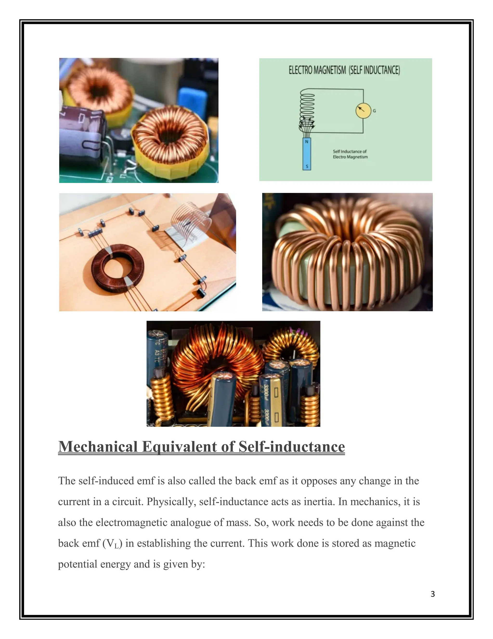
Mechanical Equivalent ofSelf-inductance
The self-induced emf is also called the back emf as it opposes any change in the
current in a circuit. Physically, self-inductance acts as inertia. In mechanics, it is
also the electromagnetic analogue of mass. So, work needs to be done against the
back emf (VL) in establishing the current. This work done is stored as magnetic
potential energy and is given by:
6.
4
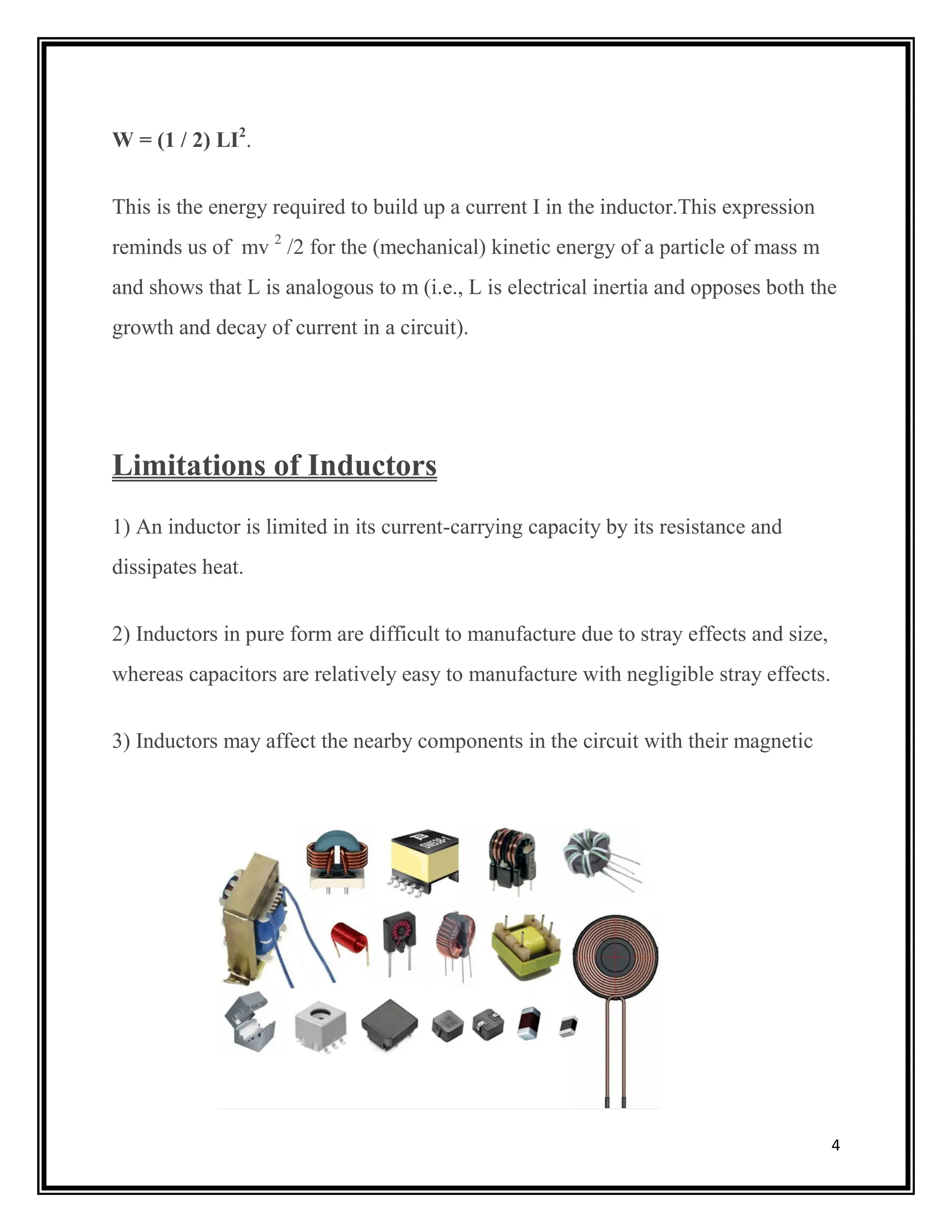
W = (1/ 2) LI2
.
This is the energy required to build up a current I in the inductor.This expression
reminds us of mv 2
/2 for the (mechanical) kinetic energy of a particle of mass m
and shows that L is analogous to m (i.e., L is electrical inertia and opposes both the
growth and decay of current in a circuit).
Limitations of Inductors
1) An inductor is limited in its current-carrying capacity by its resistance and
dissipates heat.
2) Inductors in pure form are difficult to manufacture due to stray effects and size,
whereas capacitors are relatively easy to manufacture with negligible stray effects.
3) Inductors may affect the nearby components in the circuit with their magnetic
field.
7.
5
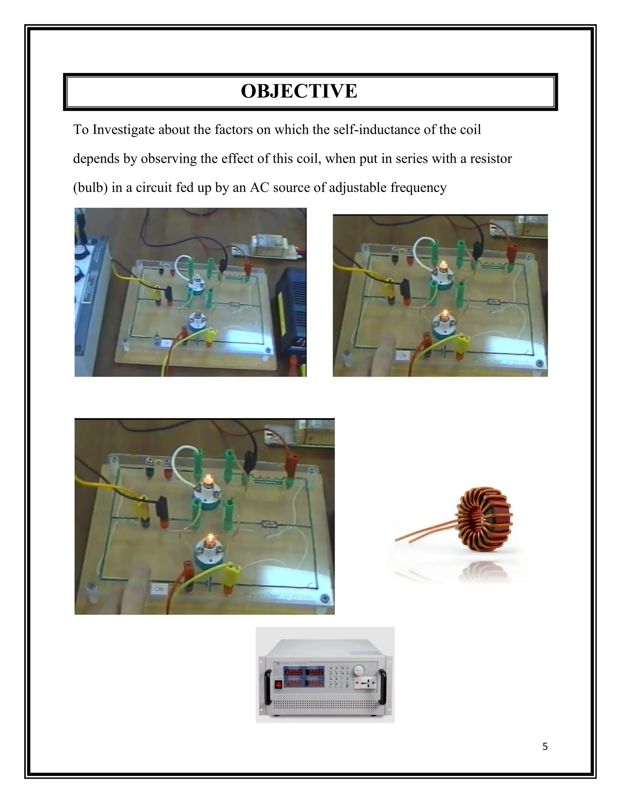
OBJECTIVE
To Investigate aboutthe factors on which the self-inductance of the coil
depends by observing the effect of this coil, when put in series with a resistor
(bulb) in a circuit fed up by an AC source of adjustable frequency
8.
6
THEORY
Self-inductance of aSolenoid
We will understand the concept with the help of an example. We will take a
solenoid having N turns; let its length be ‘l’, and the area of the cross-section be
‘A’, where current I is flowing through it. There will be a magnetic field ‘B’ at any
given point in the solenoid. Therefore, the magnetic flux per turn will be equal to B
× area of each turn.
However, B = (μ0NI)/l
Therefore, magnetic flux per turn = (μ0NIA)/l
Now, the total magnetic flux (φ) that is connected with the solenoid will be given
by the product of flux present through every turn and the total number of turns.
Φ = (μ0NIA) x N /l
That is, Φ = (μ0N2
IA) /l ….(eq 1)
If L is the self-inductance of the solenoid, then
Φ = LI …..(eq 2)
Combining the equations (1) and (2) from above, we get
L = (μ0N2
A) /l
9.
7
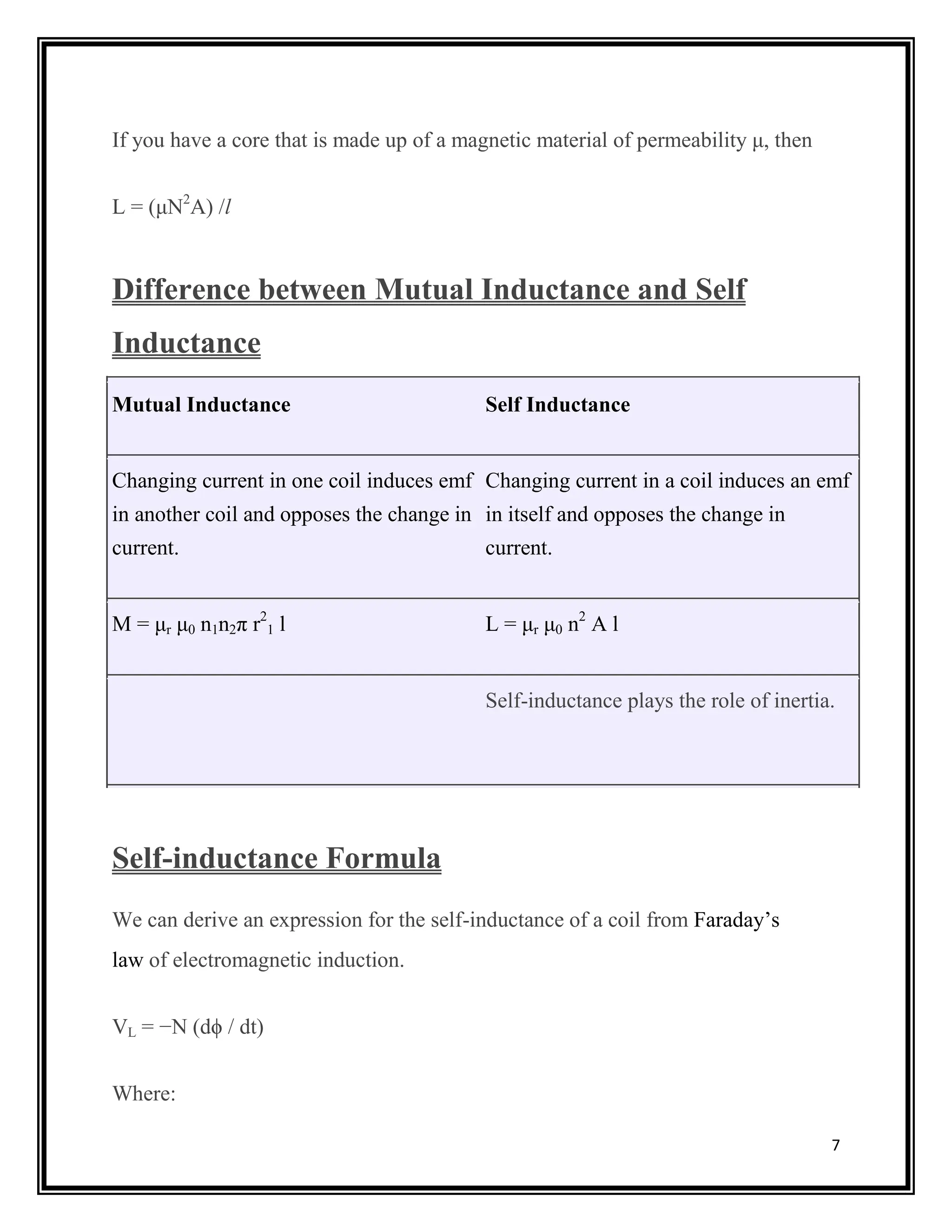
If you havea core that is made up of a magnetic material of permeability μ, then
L = (μN2
A) /l
Difference between Mutual Inductance and Self
Inductance
Mutual Inductance Self Inductance
Changing current in one coil induces emf
in another coil and opposes the change in
current.
Changing current in a coil induces an emf
in itself and opposes the change in
current.
M = μr μ0 n1n2π r2
1 l L = μr μ0 n2
A l
Self-inductance plays the role of inertia.
Self-inductance Formula
We can derive an expression for the self-inductance of a coil from Faraday’s
law of electromagnetic induction.
VL = −N (dϕ / dt)
Where:
10.
8
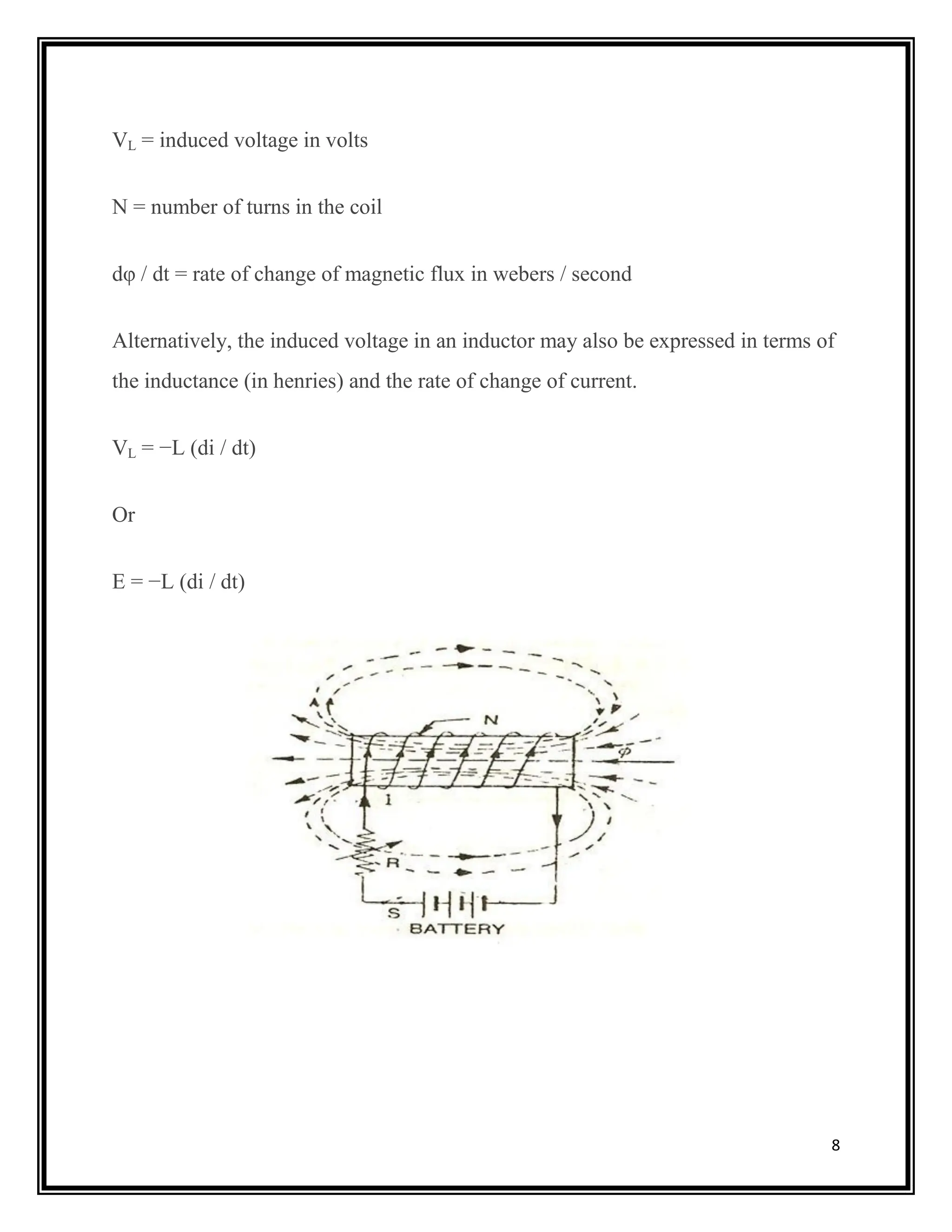
VL = inducedvoltage in volts
N = number of turns in the coil
dφ / dt = rate of change of magnetic flux in webers / second
Alternatively, the induced voltage in an inductor may also be expressed in terms of
the inductance (in henries) and the rate of change of current.
VL = −L (di / dt)
Or
E = −L (di / dt)
11.
9
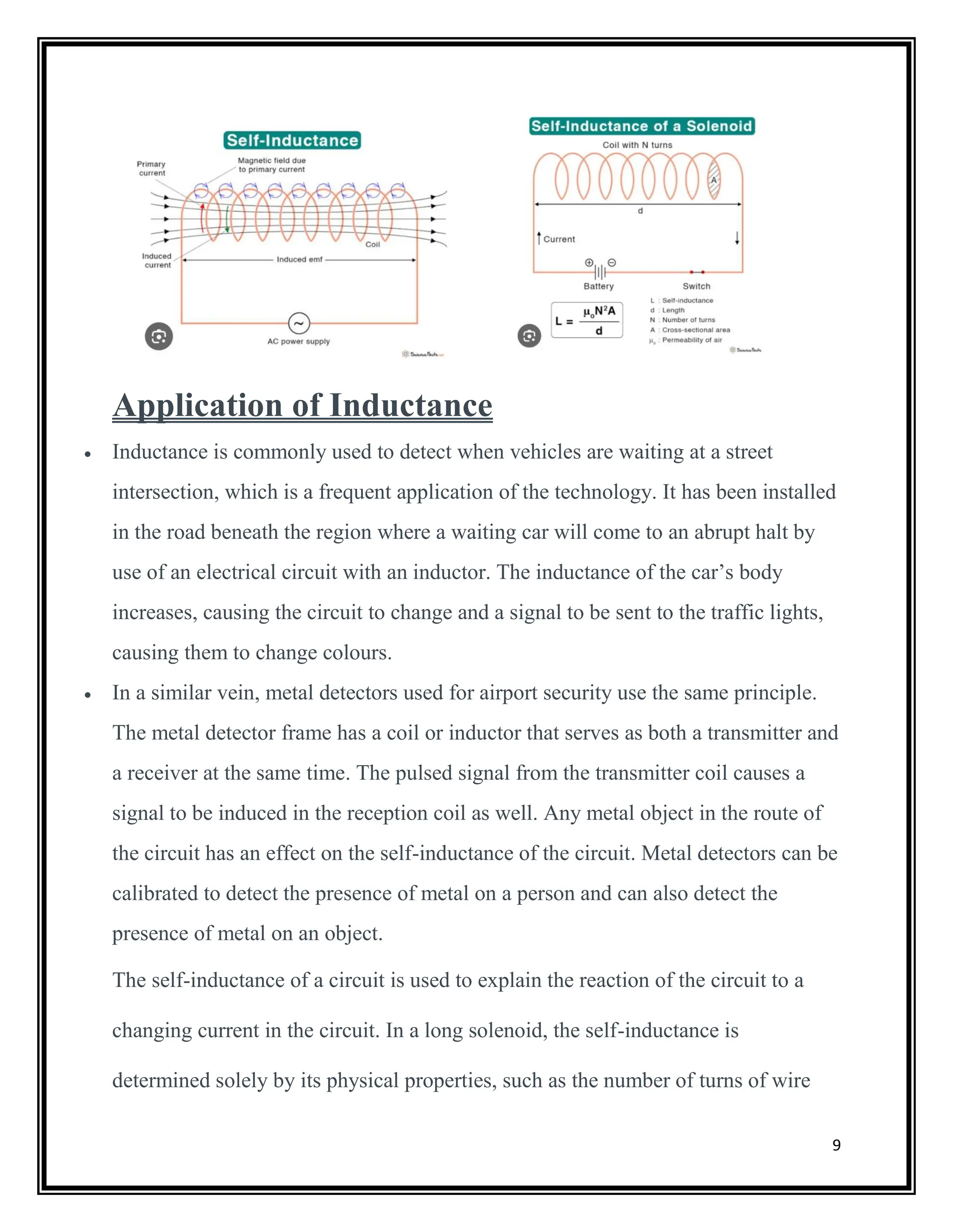
Application of Inductance
Inductance is commonly used to detect when vehicles are waiting at a street
intersection, which is a frequent application of the technology. It has been installed
in the road beneath the region where a waiting car will come to an abrupt halt by
use of an electrical circuit with an inductor. The inductance of the car’s body
increases, causing the circuit to change and a signal to be sent to the traffic lights,
causing them to change colours.
In a similar vein, metal detectors used for airport security use the same principle.
The metal detector frame has a coil or inductor that serves as both a transmitter and
a receiver at the same time. The pulsed signal from the transmitter coil causes a
signal to be induced in the reception coil as well. Any metal object in the route of
the circuit has an effect on the self-inductance of the circuit. Metal detectors can be
calibrated to detect the presence of metal on a person and can also detect the
presence of metal on an object.
The self-inductance of a circuit is used to explain the reaction of the circuit to a
changing current in the circuit. In a long solenoid, the self-inductance is
determined solely by its physical properties, such as the number of turns of wire
12.
10
per unit lengthand the volume of the solenoid, and is not affected by the magnetic
field or the current.
Self-Induction L of a coil depends upon-
1. The size and shape of the coil.
2. The number of turns N.
3. The magnetic property of the medium within the coil in which the flux is
present.
Note: Self-induction L does not depend on the current I.
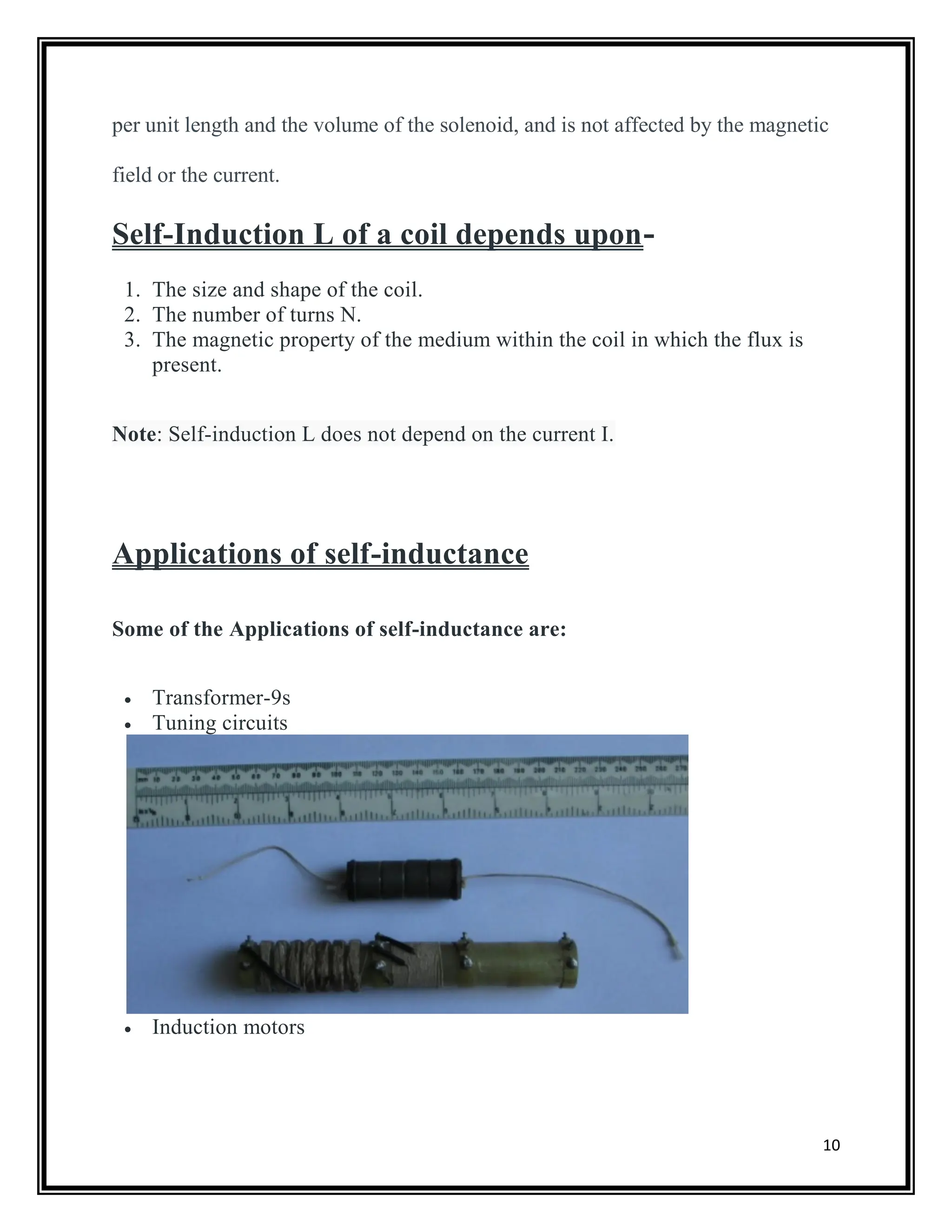
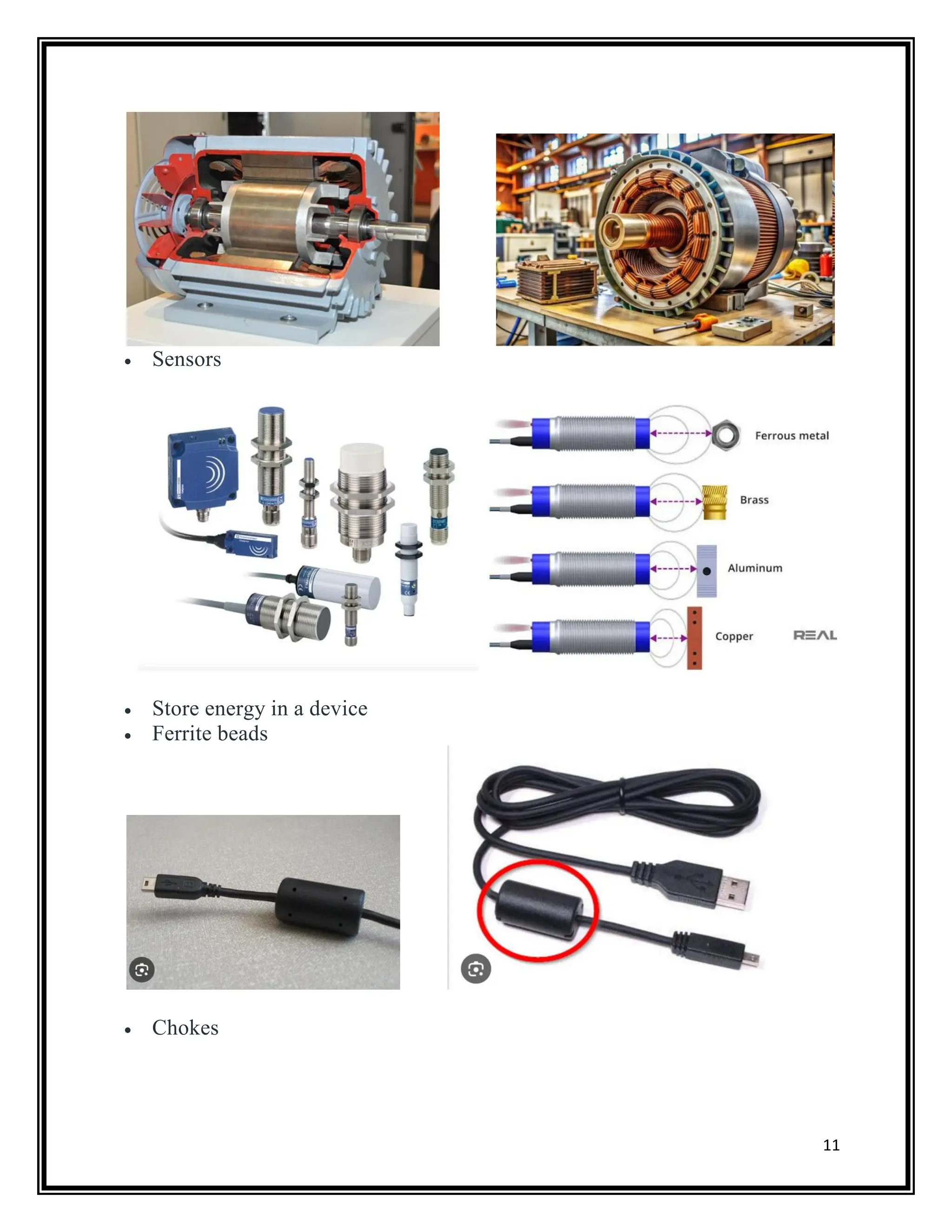
Applications of self-inductance
Some of the Applications of self-inductance are:
Transformer-9s
Tuning circuits
Induction motors
12
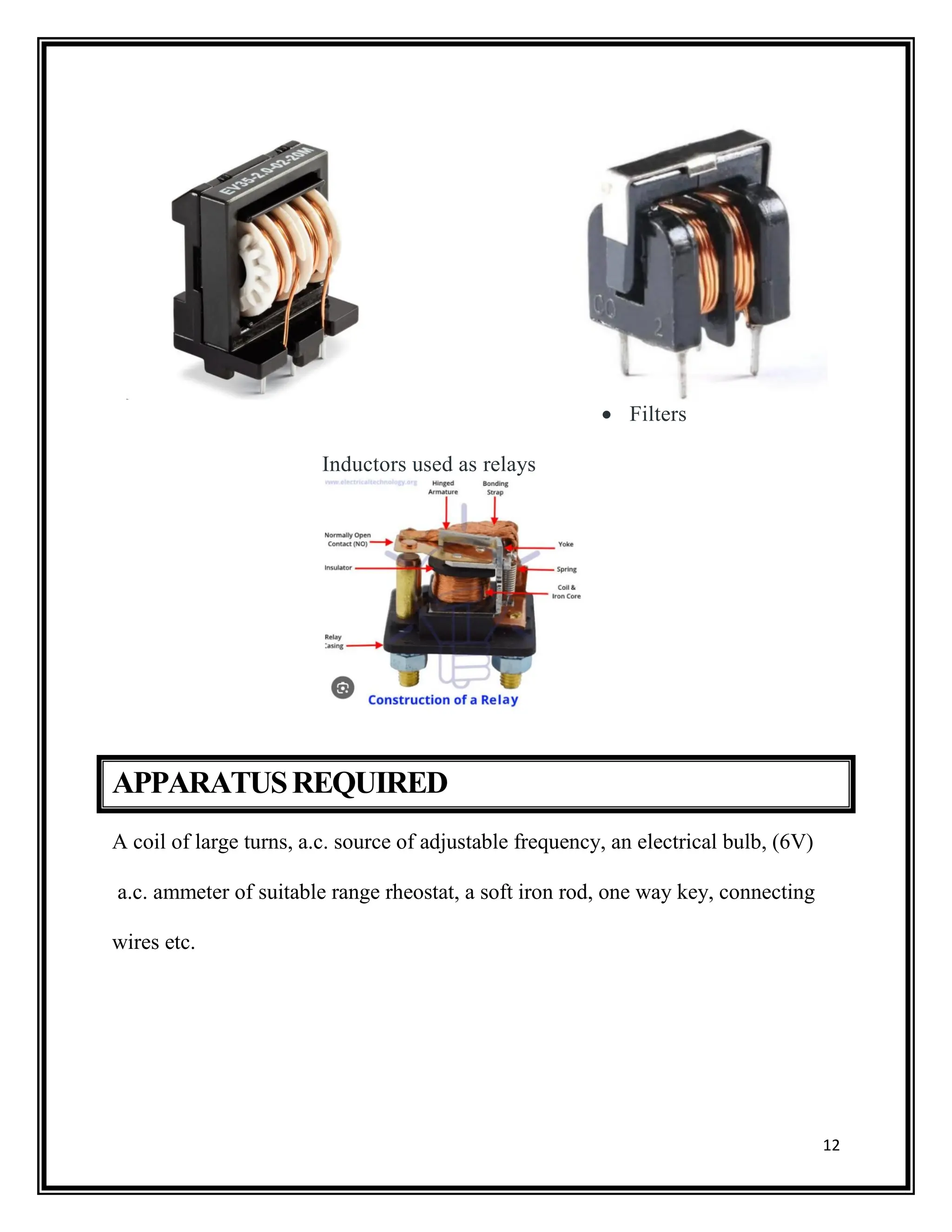
Filters
Inductors usedas relays
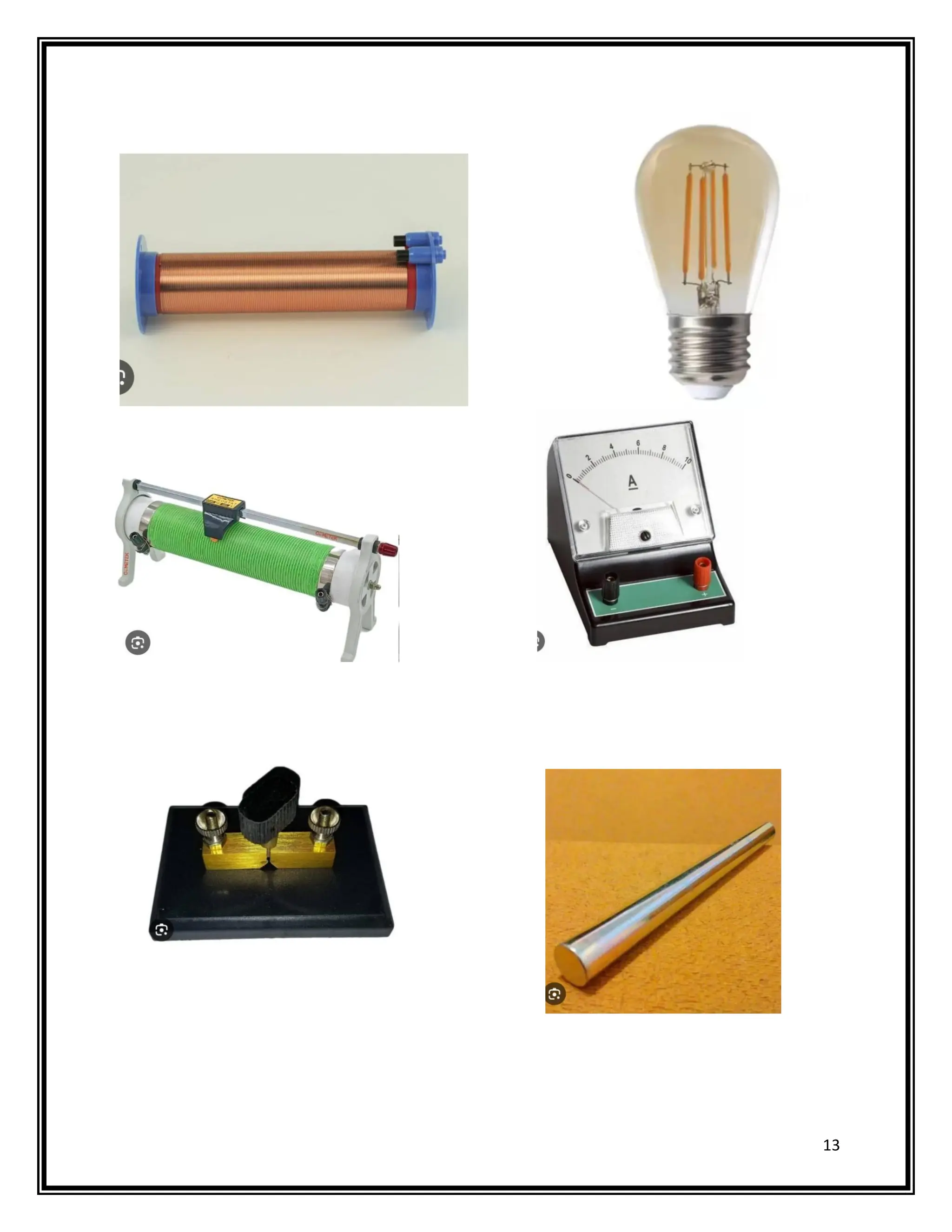
APPARATUSREQUIRED
A coil of large turns, a.c. source of adjustable frequency, an electrical bulb, (6V)
a.c. ammeter of suitable range rheostat, a soft iron rod, one way key, connecting
wires etc.
14
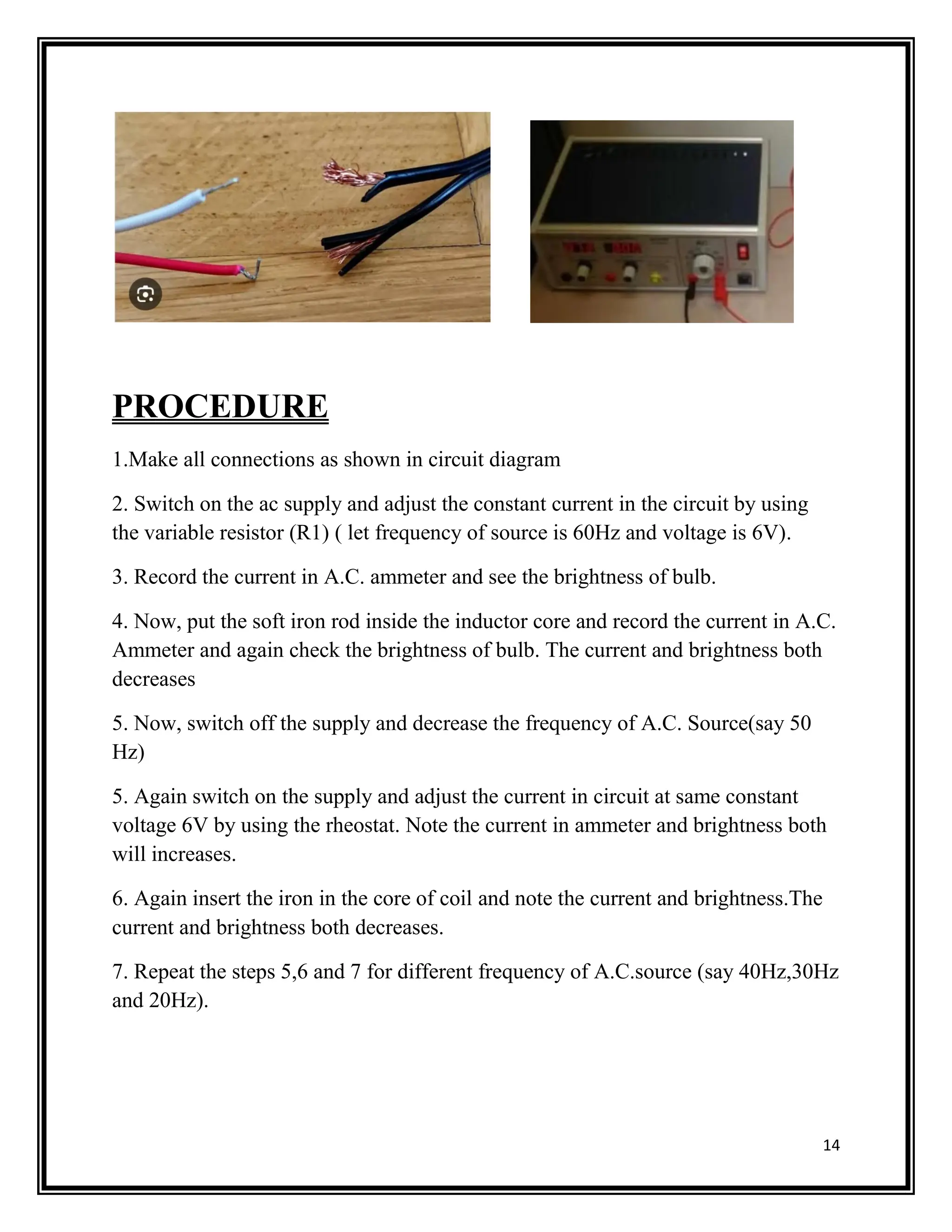
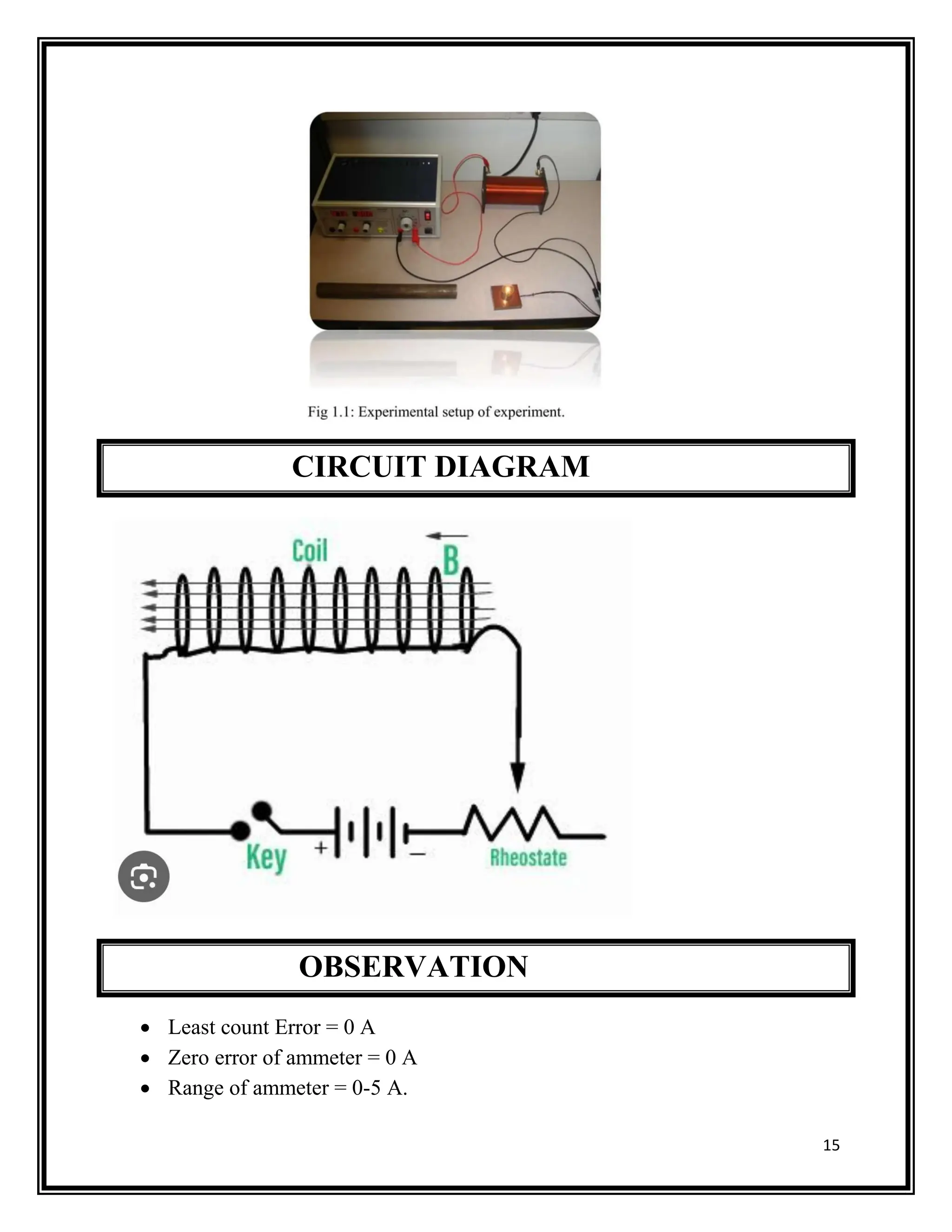
PROCEDURE
1.Make all connectionsas shown in circuit diagram
2. Switch on the ac supply and adjust the constant current in the circuit by using
the variable resistor (R1) ( let frequency of source is 60Hz and voltage is 6V).
3. Record the current in A.C. ammeter and see the brightness of bulb.
4. Now, put the soft iron rod inside the inductor core and record the current in A.C.
Ammeter and again check the brightness of bulb. The current and brightness both
decreases
5. Now, switch off the supply and decrease the frequency of A.C. Source(say 50
Hz)
5. Again switch on the supply and adjust the current in circuit at same constant
voltage 6V by using the rheostat. Note the current in ammeter and brightness both
will increases.
6. Again insert the iron in the core of coil and note the current and brightness.The
current and brightness both decreases.
7. Repeat the steps 5,6 and 7 for different frequency of A.C.source (say 40Hz,30Hz
and 20Hz).
16
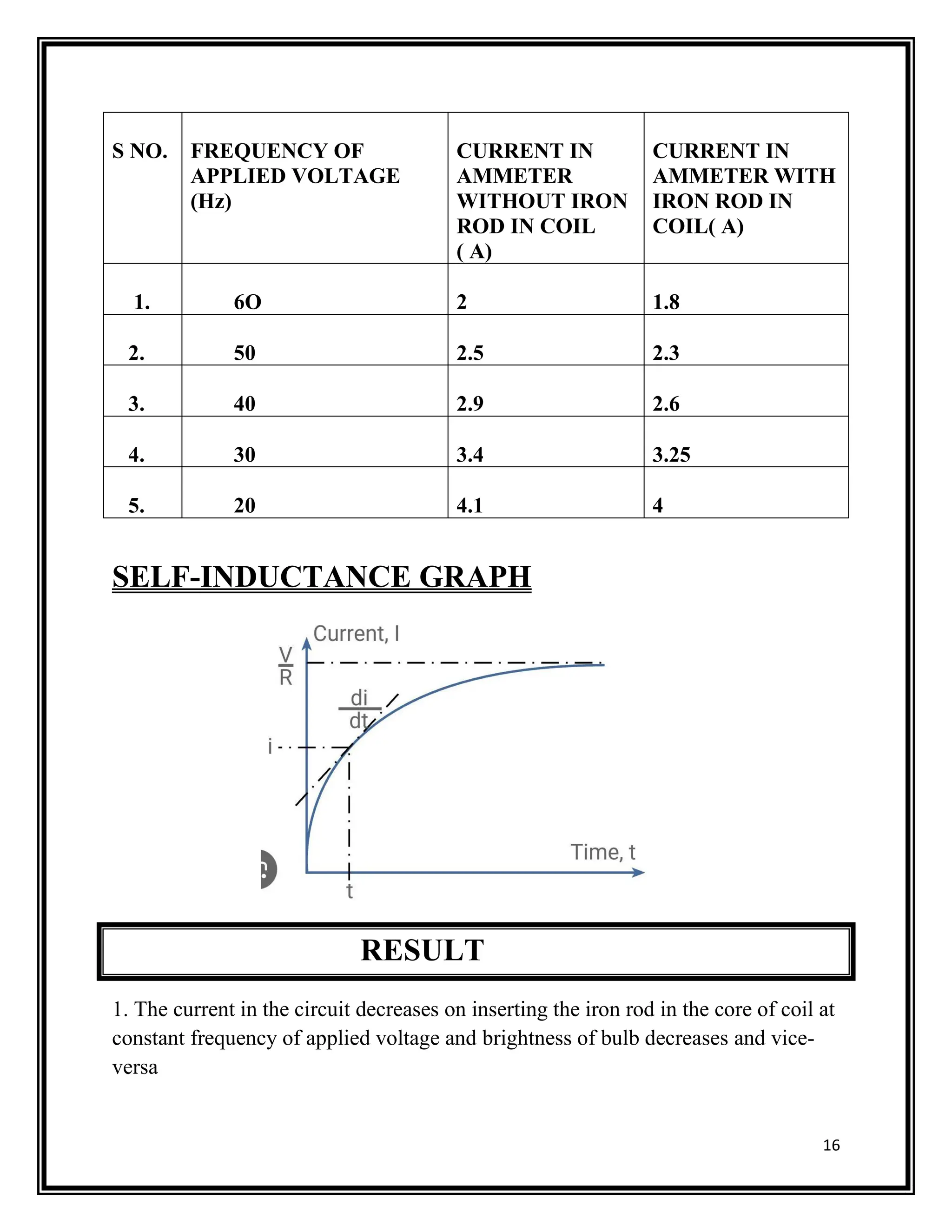
S NO. FREQUENCYOF
APPLIED VOLTAGE
(Hz)
CURRENT IN
AMMETER
WITHOUT IRON
ROD IN COIL
( A)
CURRENT IN
AMMETER WITH
IRON ROD IN
COIL( A)
1. 6O 2 1.8
2. 50 2.5 2.3
3. 40 2.9 2.6
4. 30 3.4 3.25
5. 20 4.1 4
SELF-INDUCTANCE GRAPH
RESULT
1. The current in the circuit decreases on inserting the iron rod in the core of coil at
constant frequency of applied voltage and brightness of bulb decreases and vice-
versa
19.
17
2. The currentin the circuit increases on decreasing the frequency of applied
voltage and vice-versa. Therefore, the brightness of bulb increases.
PRECAUTIONS
1. The coil should have large number of turns.
2. Current should be passed for a small time to avoid the heating effect.
3. There should not be parallax in taking the reading of ammeter.
SOURCE OF ERROR
1. The resistance of circuit may increases slightly due to heating effect of current.
2. There may be eddy current.
CONCLUSION
THE FACTORS ARE
NUMBER OF WIRE WRAPS, OR “TURNS” IN THE COIL.
COIL AREA.
COIL LENGTH.
CORE MATERIAL.