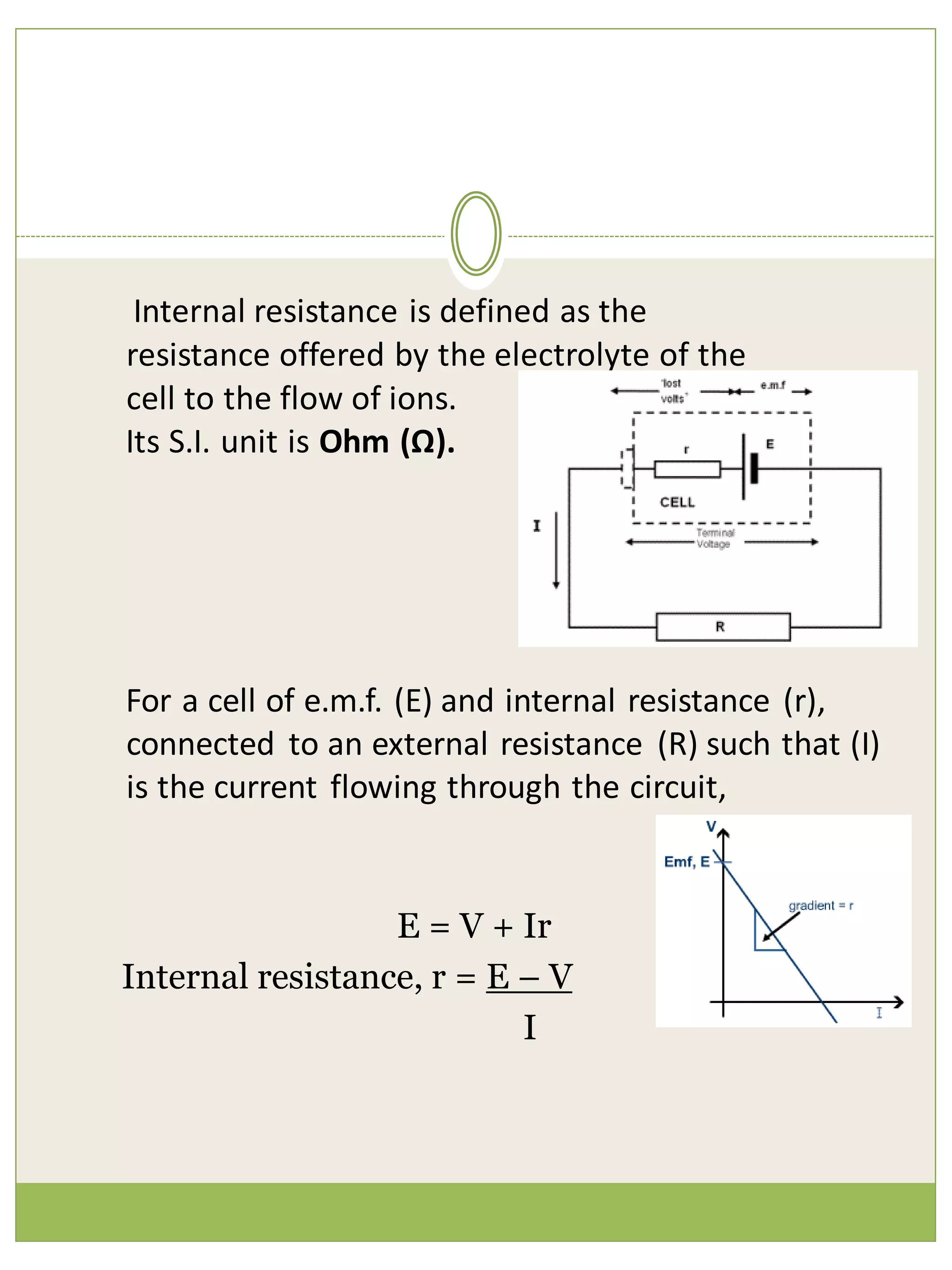
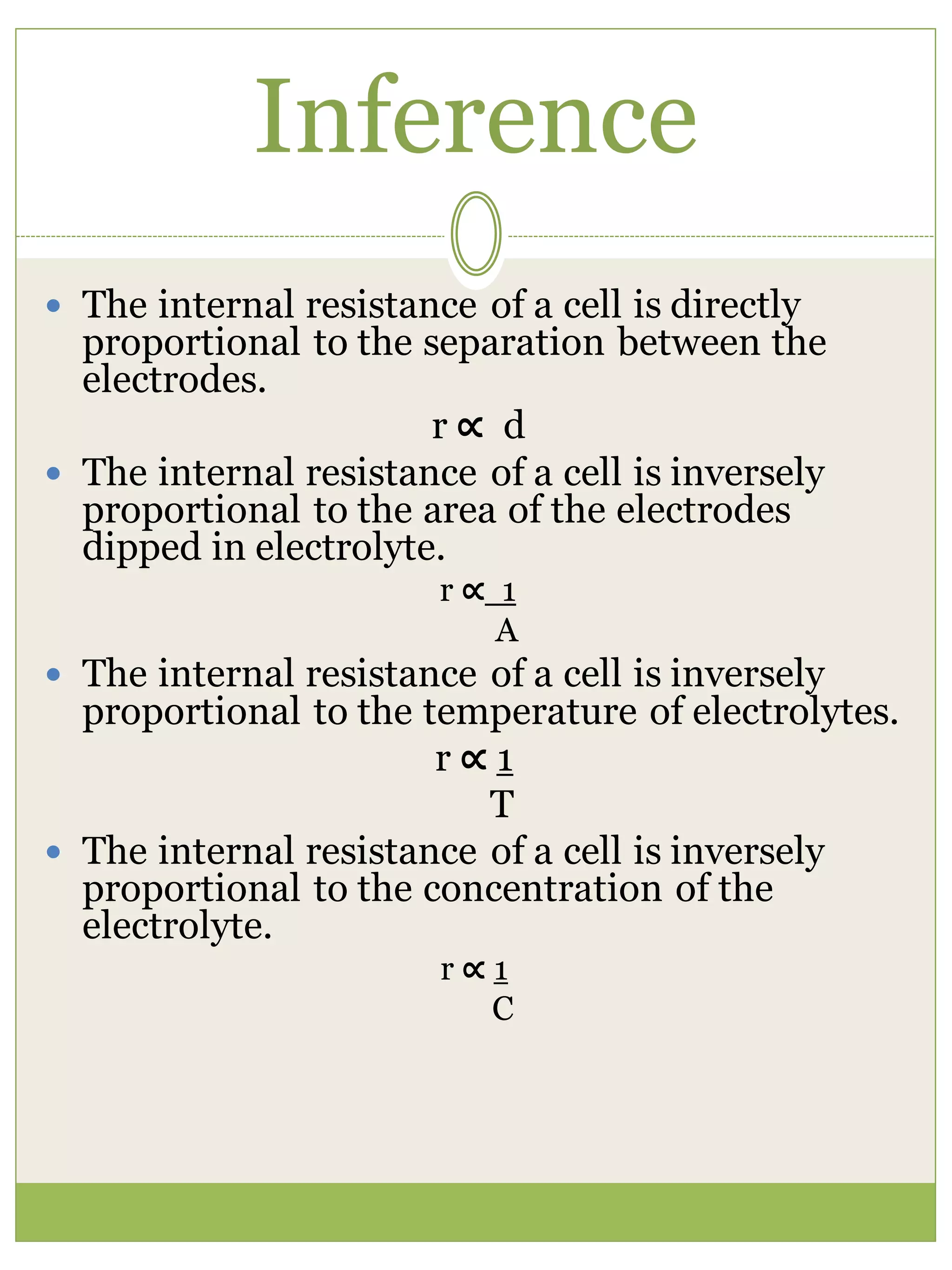
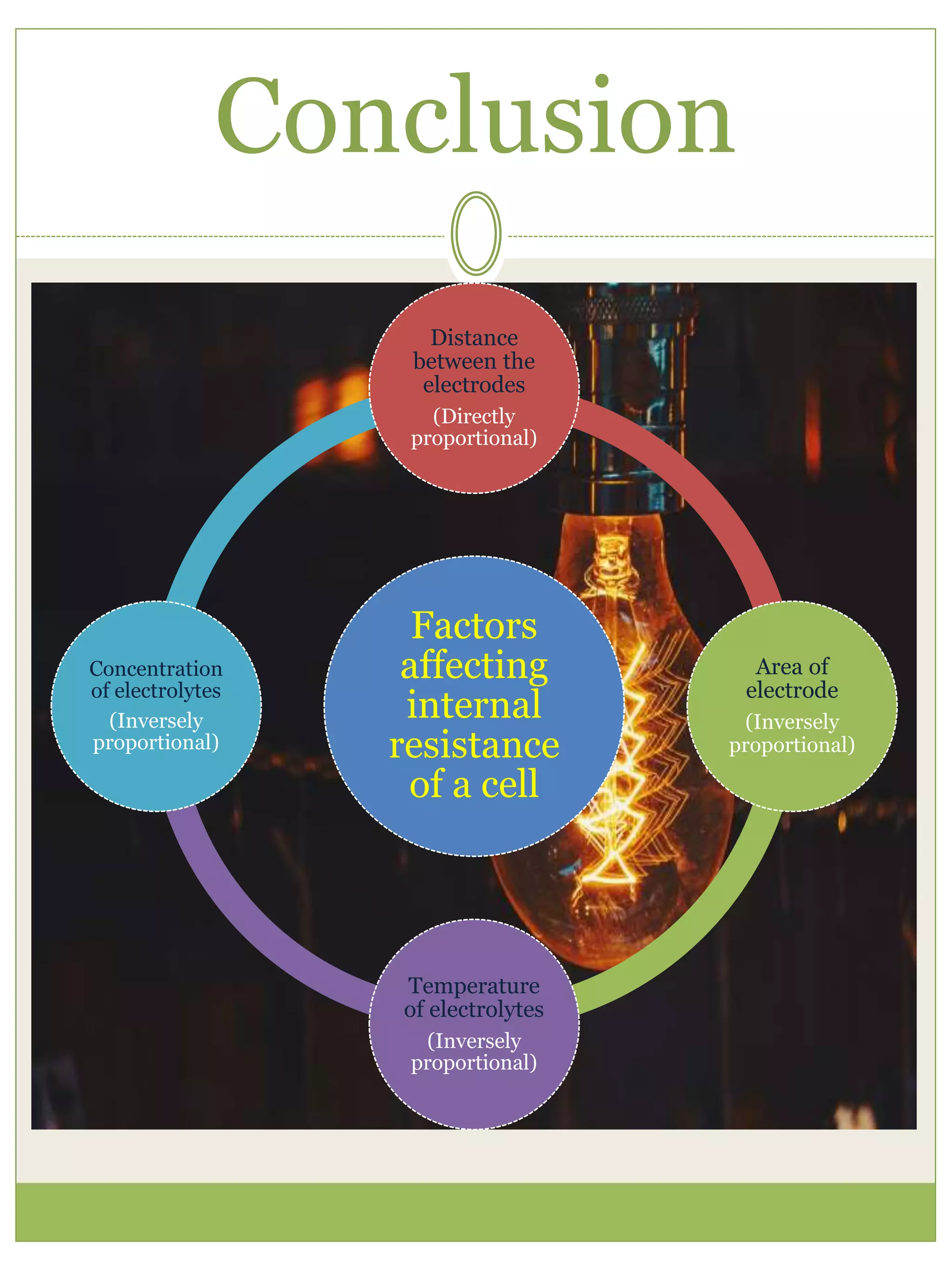
PHYSICS INVESTIGATORY
PROJECT
Kendriya Vidyalaya
No.1 Sagar
OJASWI MISHRA
XII ‘B’
Index
S.No. Heading
1. Certification
2. Acknowledgement
3. Aim
4. Introduction
5. Apparatus
6. Theory
7. Procedure
8. Observations
9. Result
10. Inference
11. Precaution
12. Sources of error
13. Conclusion
14. Bibliography
Certification
This is to certify that Ojaswi Mishra, a
student of class XII-B, has completed
research successfully on the project title
“Factors on which internal resistance of
cell depends” under the guidance of ,
Mr. R.G. Goswami (subject teacher)
during the year 2020-21 in partial
fulfillment of chemistry practical
examination conducted by AISSCE, New
Delhi.
Signature of examiner
Signature of Signature of
chemistry teacher Principal
Acknowledgement
I would like to take this opportunity
to thank my teacher, Mr. R.G.
Goswami whose support, guidance
and encouragement have enable me
to complete this project.
Aim
“Factors on
which internal
resistance of
cell depends”
Introduction
There is a great need of batteries in our daily use
electronic appliances and the use is increasing
every day. Thus, the batteries need to be made
more powerful so that their potential can be
increased greatly. This project report is based on
practical analysis for the factors affecting the
internal resistance of a cell.
When the internal resistance of the cell is decreased
we can increase the potential difference across it, and
hence make it more reliable.
Internal Resistance
The resistance within a battery, or other
voltage source, that causes a drop in the
source voltage when there is a current.
Internal resistance is defined as the
resistance offered by the electrolyte of the
cell to the flow of ions.
Its S.I. unit is Ohm (Ω).
For a cell of e.m.f. (E) and internal resistance (r),
connected to an external resistance (R) such that (I)
is the current flowing through the circuit,
E = V + Ir
Internal resistance, r = E – V
I
Apparatus
A potentiometer, a battery (or battery eliminator),
two one way keys, a rheostat, a galvanometer, a
resistance box, an ammeter, a cell (Leclanche cell),
a jockey, a setsquare, connecting wires and sand
paper.
Theory
The internal resistance of a cell is the resistance
offered by its electrolyte to the flow of ions. The
internal resistance of a cell
 Is directly proportional to the distance between the
electrodes. Let x be the distance between the
electrodes, then,
r ∝ x
 Is inversely proportional to facing surface area of
the electrodes in electrolyte. Let A be the surface
area of the electrodes, then,
r ∝ 1/A
 Decreases with increase in temperature of
electrolyte.
 Is inversely proportional to concentration of
electrolyte.
 The internal resistance of a cell is given by:
r = E – V
I
Circuit diagram
The above circuit includes:
 A power supply
 Two one way keys
 A galvanometer
 A Resistance Box
 A Leclanche cell
 A shunt resistance
Procedure
 Clean the ends of the connecting wires with sand paper
and make tight connections according to the circuit
diagram.
 Tighten the plugs of the resistance box.
 Check the e.m.f. of the battery and of the cell and make
sure that e.m.f. of the battery is more than that of the cell,
otherwise null or balance point will not be obtained.
To study variation of internal resistance with distance of
Separation
 Keep both the electrodes at a distance of 16 cm.
 Take maximum current from the battery,
making rheostat resistance small.
 Without inserting a plug in key K2, adjust the rheostat so
that a null point is obtained on the last wire of the
potentiometer.
 Determine the position of the null point accurately
using a set square and measure the balancing length
(l1) between the null point and the end P.
 Next introduce plugs in both keys K1 and K2. At the same
time, take out a small resistance (1 – 5W)
from the shunt resistance box connected in
parallel with the cell.
 Slide the jockey along a potentiometer wire and
obtain the null point.
 Measure the balancing length (l2) from end P.
Record these observations.
 Now keep the electrodes 12 cm apart.
 Then remove the plugs of keys K1 and K2. Wait
for some time and repeat steps 7 to 10.
 Next, keep the electrodes 9 cm apart to obtain
another set of observations.
To study variation of internal resistance with area
of electrodes
 Keeping all other factors constant, increase the
area of electrodes in the electrolyte by dipping
them into the electrolyte at different depths for
each observation.
 Obtain three such observations by repeating
steps 7 to 10. Record your readings.
To study variation of internal resistance with
concentration of electrolyte.
 Keeping all other factors constant, decrease the
concentration of electrolyte by adding distilled water for
different observations.
 Obtain three such observations by repeating step 7 to
10. Record your readings.
Observations
S.No. Ammeter
reading
Position of null
point
(cm)
Shunt
Resistance
(R)
Internal
Resistance
(r)
With R
(l1)
Without
R (l2)
1. 0.3 660.5 35.5 1 0.94
2. 0.3 660.5 77.2 2 1.77
3. 0.3 660.5 108.3 3 2.51
Table for effect of separation between electrodes:
S.No Separation
between
l1(cm) and
d(cm)
Balancing
point
l2(cm)
Balancing
point
r(Ω)
Internal
Resistance
(r)
r
d
electrodes
1. 1.2 326.6 276.9 0.456 0.38
2. 2.5 320.7 219.1 0.45 0.38
3. 3.7 660.5 350.9 1.406 0.38
Table for effect of temperature:
S.No Temperature
T(°C)
l1
(cm)
l2
(cm)
Resistance
R(Ω)
Internal
Resistance
r (Ω)
Tr
(ΩK)
1. 1.2 326.6 276.9 0.456 0.38 301.44
2. 2.5 320.7 219.1 0.950 0.38 219.96
3. 3.7 660.5 350.9 1.406 0.38 283.87
Result
The Electromotive Force of the
cell is constant and is equal to
E = 0.98 Volt.
Inference
 The internal resistance of a cell is directly
proportional to the separation between the
electrodes.
r ∝ d
 The internal resistance of a cell is inversely
proportional to the area of the electrodes
dipped in electrolyte.
r ∝ 1
A
 The internal resistance of a cell is inversely
proportional to the temperature of electrolytes.
r ∝ 1
T
 The internal resistance of a cell is inversely
proportional to the concentration of the
electrolyte.
r ∝ 1
C
Precaution
 The connections should be neat, clean
and tight.
 The plugs should be introduced in the
keys only when the observations are to
be taken.
 The positive polls of the battery E and
cells E1 and E2 should all be connected
to the terminal at the zero of the wires.
 The jockey key should not be rubbed
along the wire. It should touch the wire
gently.
 The ammeter reading should remain
constant for a particular set of
observation. If necessary, adjust the
rheostat for this purpose.
Sources of error
 The auxiliary battery may not be
fully charged.
 The potentiometer wire may not be
of uniform cross-section and
material density throughout its
length.
 End resistances may not be zero.
Conclusion
Factors
affecting
internal
resistance
of a cell
Distance
between the
electrodes
(Directly
proportional)
Area of
electrode
(Inversely
proportional)
Temperature
of electrolytes
(Inversely
proportional)
Concentration
of electrolytes
(Inversely
proportional)
Bibliography
•Help with
teacher.
•Help with
parents
and elders.
•Help from
library.
•Help from
internet.

Physics investigatory project on different emf of cell

  • 1.
  • 2.
    Index S.No. Heading 1. Certification 2.Acknowledgement 3. Aim 4. Introduction 5. Apparatus 6. Theory 7. Procedure 8. Observations 9. Result 10. Inference 11. Precaution 12. Sources of error 13. Conclusion 14. Bibliography
  • 3.
    Certification This is tocertify that Ojaswi Mishra, a student of class XII-B, has completed research successfully on the project title “Factors on which internal resistance of cell depends” under the guidance of , Mr. R.G. Goswami (subject teacher) during the year 2020-21 in partial fulfillment of chemistry practical examination conducted by AISSCE, New Delhi. Signature of examiner Signature of Signature of chemistry teacher Principal
  • 4.
    Acknowledgement I would liketo take this opportunity to thank my teacher, Mr. R.G. Goswami whose support, guidance and encouragement have enable me to complete this project.
  • 5.
  • 6.
    Introduction There is agreat need of batteries in our daily use electronic appliances and the use is increasing every day. Thus, the batteries need to be made more powerful so that their potential can be increased greatly. This project report is based on practical analysis for the factors affecting the internal resistance of a cell. When the internal resistance of the cell is decreased we can increase the potential difference across it, and hence make it more reliable. Internal Resistance The resistance within a battery, or other voltage source, that causes a drop in the source voltage when there is a current.
  • 7.
    Internal resistance isdefined as the resistance offered by the electrolyte of the cell to the flow of ions. Its S.I. unit is Ohm (Ω). For a cell of e.m.f. (E) and internal resistance (r), connected to an external resistance (R) such that (I) is the current flowing through the circuit, E = V + Ir Internal resistance, r = E – V I
  • 9.
    Apparatus A potentiometer, abattery (or battery eliminator), two one way keys, a rheostat, a galvanometer, a resistance box, an ammeter, a cell (Leclanche cell), a jockey, a setsquare, connecting wires and sand paper.
  • 10.
    Theory The internal resistanceof a cell is the resistance offered by its electrolyte to the flow of ions. The internal resistance of a cell  Is directly proportional to the distance between the electrodes. Let x be the distance between the electrodes, then, r ∝ x  Is inversely proportional to facing surface area of the electrodes in electrolyte. Let A be the surface area of the electrodes, then, r ∝ 1/A  Decreases with increase in temperature of electrolyte.  Is inversely proportional to concentration of electrolyte.  The internal resistance of a cell is given by: r = E – V I
  • 11.
    Circuit diagram The abovecircuit includes:  A power supply  Two one way keys  A galvanometer  A Resistance Box  A Leclanche cell  A shunt resistance
  • 12.
    Procedure  Clean theends of the connecting wires with sand paper and make tight connections according to the circuit diagram.  Tighten the plugs of the resistance box.  Check the e.m.f. of the battery and of the cell and make sure that e.m.f. of the battery is more than that of the cell, otherwise null or balance point will not be obtained. To study variation of internal resistance with distance of Separation  Keep both the electrodes at a distance of 16 cm.  Take maximum current from the battery, making rheostat resistance small.  Without inserting a plug in key K2, adjust the rheostat so that a null point is obtained on the last wire of the potentiometer.  Determine the position of the null point accurately using a set square and measure the balancing length (l1) between the null point and the end P.  Next introduce plugs in both keys K1 and K2. At the same time, take out a small resistance (1 – 5W)
  • 13.
    from the shuntresistance box connected in parallel with the cell.  Slide the jockey along a potentiometer wire and obtain the null point.  Measure the balancing length (l2) from end P. Record these observations.  Now keep the electrodes 12 cm apart.  Then remove the plugs of keys K1 and K2. Wait for some time and repeat steps 7 to 10.  Next, keep the electrodes 9 cm apart to obtain another set of observations. To study variation of internal resistance with area of electrodes  Keeping all other factors constant, increase the area of electrodes in the electrolyte by dipping them into the electrolyte at different depths for each observation.  Obtain three such observations by repeating steps 7 to 10. Record your readings.
  • 14.
    To study variationof internal resistance with concentration of electrolyte.  Keeping all other factors constant, decrease the concentration of electrolyte by adding distilled water for different observations.  Obtain three such observations by repeating step 7 to 10. Record your readings.
  • 16.
    Observations S.No. Ammeter reading Position ofnull point (cm) Shunt Resistance (R) Internal Resistance (r) With R (l1) Without R (l2) 1. 0.3 660.5 35.5 1 0.94 2. 0.3 660.5 77.2 2 1.77 3. 0.3 660.5 108.3 3 2.51 Table for effect of separation between electrodes: S.No Separation between l1(cm) and d(cm) Balancing point l2(cm) Balancing point r(Ω) Internal Resistance (r) r d electrodes 1. 1.2 326.6 276.9 0.456 0.38 2. 2.5 320.7 219.1 0.45 0.38 3. 3.7 660.5 350.9 1.406 0.38
  • 17.
    Table for effectof temperature: S.No Temperature T(°C) l1 (cm) l2 (cm) Resistance R(Ω) Internal Resistance r (Ω) Tr (ΩK) 1. 1.2 326.6 276.9 0.456 0.38 301.44 2. 2.5 320.7 219.1 0.950 0.38 219.96 3. 3.7 660.5 350.9 1.406 0.38 283.87
  • 18.
    Result The Electromotive Forceof the cell is constant and is equal to E = 0.98 Volt.
  • 19.
    Inference  The internalresistance of a cell is directly proportional to the separation between the electrodes. r ∝ d  The internal resistance of a cell is inversely proportional to the area of the electrodes dipped in electrolyte. r ∝ 1 A  The internal resistance of a cell is inversely proportional to the temperature of electrolytes. r ∝ 1 T  The internal resistance of a cell is inversely proportional to the concentration of the electrolyte. r ∝ 1 C
  • 21.
    Precaution  The connectionsshould be neat, clean and tight.  The plugs should be introduced in the keys only when the observations are to be taken.  The positive polls of the battery E and cells E1 and E2 should all be connected to the terminal at the zero of the wires.  The jockey key should not be rubbed along the wire. It should touch the wire gently.  The ammeter reading should remain constant for a particular set of observation. If necessary, adjust the rheostat for this purpose.
  • 22.
    Sources of error The auxiliary battery may not be fully charged.  The potentiometer wire may not be of uniform cross-section and material density throughout its length.  End resistances may not be zero.
  • 23.
    Conclusion Factors affecting internal resistance of a cell Distance betweenthe electrodes (Directly proportional) Area of electrode (Inversely proportional) Temperature of electrolytes (Inversely proportional) Concentration of electrolytes (Inversely proportional)
  • 24.
    Bibliography •Help with teacher. •Help with parents andelders. •Help from library. •Help from internet.