Who AM I- cat /dev/falcnix
# reading my identity at 115200 baud
● Co-Founder of IoTSRG (IoT Security Research Group)
○ Its where we come out with the coolest research
● Core Team member of CYSINFO
● Professionally I Lead the Payments Hardware Security Evaluation Lab at
SISA Information Security
3.
Agenda
● Why UARTin 2025/2026?
● Why not JTAG/SWD here?
● UART 101
● Data Transmission
● Step 0 : Opening the device & visual ID of candidate pins
● Step 2 : Identification of baud rate
● Step 3 : Identification of Rx (target)
● Step 4 : UART Brute force
● Jtagulator
● Why our tool
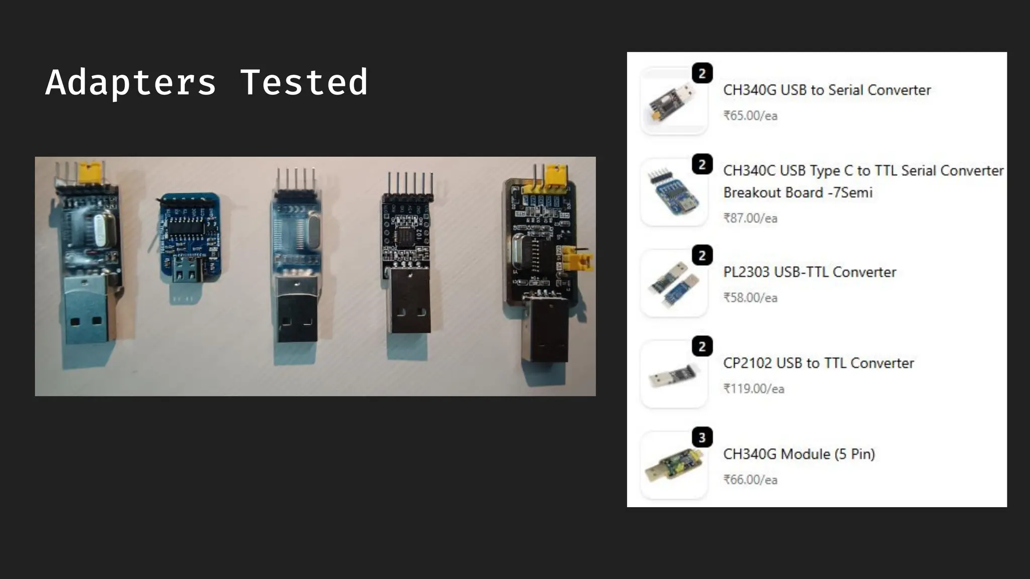
● Adapters Tested
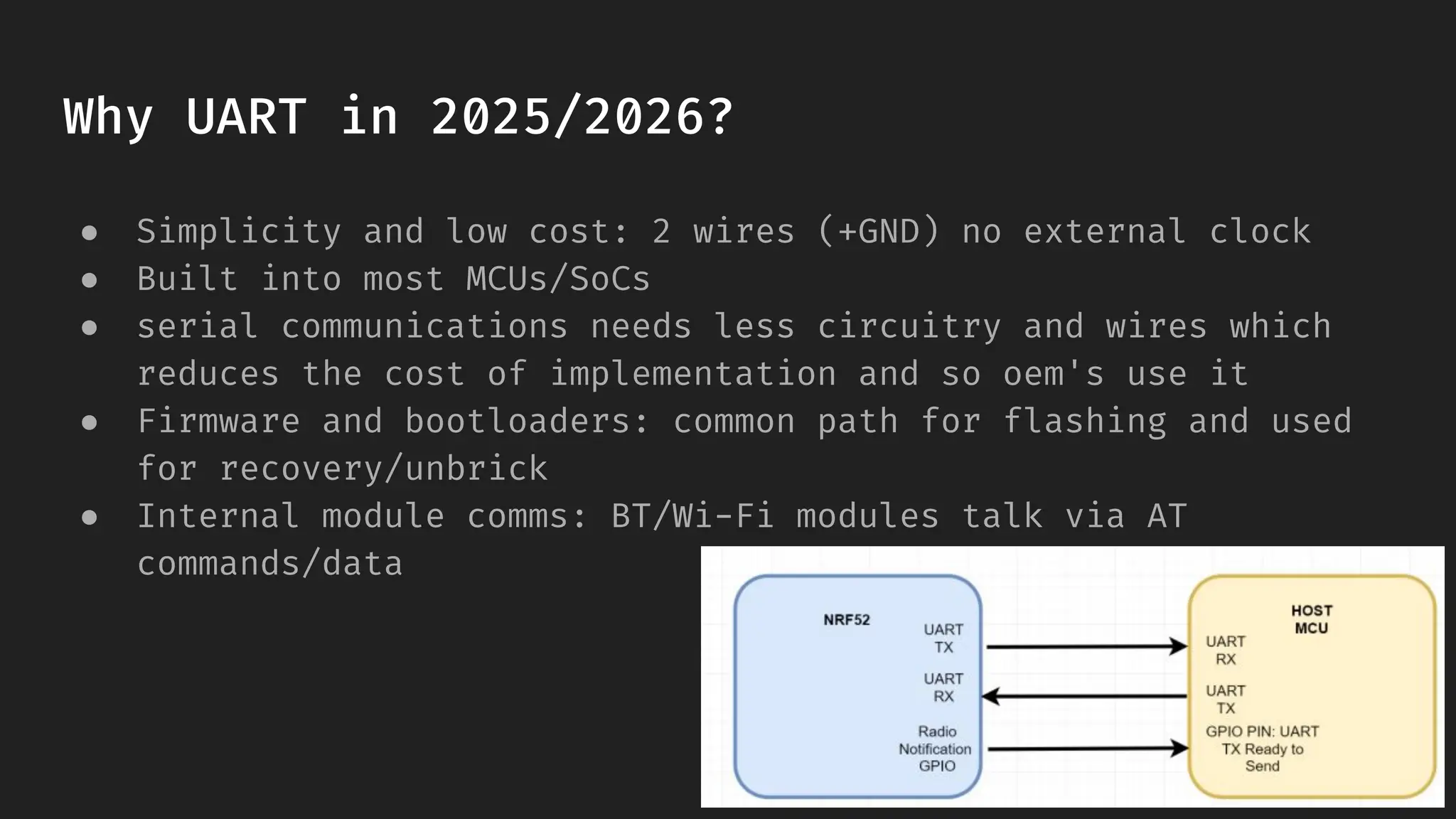
Why UART in2025/2026?
● Simplicity and low cost: 2 wires (+GND) no external clock
● Built into most MCUs/SoCs
● serial communications needs less circuitry and wires which
reduces the cost of implementation and so oem's use it
● Firmware and bootloaders: common path for flashing and used
for recovery/unbrick
● Internal module comms: BT/Wi-Fi modules talk via AT
commands/data
6.
Why not JTAG/SWDhere?
● We are adding multiple supporting features in future releases
● SWD
● JTAG
● I2C
● etc
7.
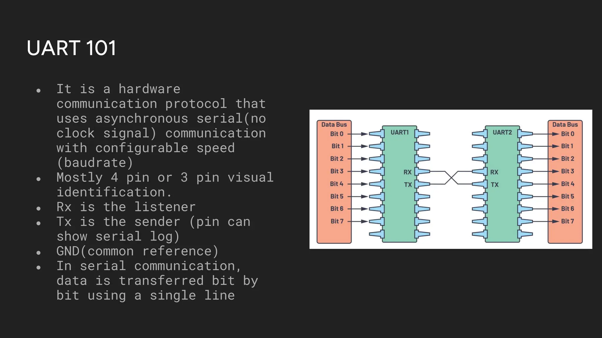
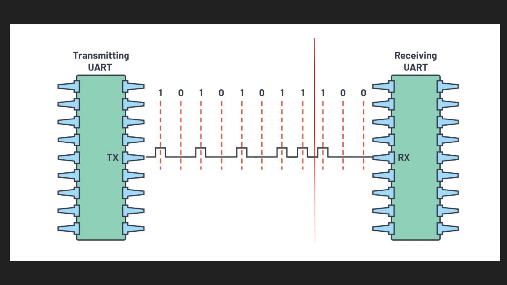
UART 101
● Itis a hardware
communication protocol that
uses asynchronous serial(no
clock signal) communication
with configurable speed
(baudrate)
● Mostly 4 pin or 3 pin visual
identification.
● Rx is the listener
● Tx is the sender (pin can
show serial log)
● GND(common reference)
● In serial communication,
data is transferred bit by
bit using a single line
8.
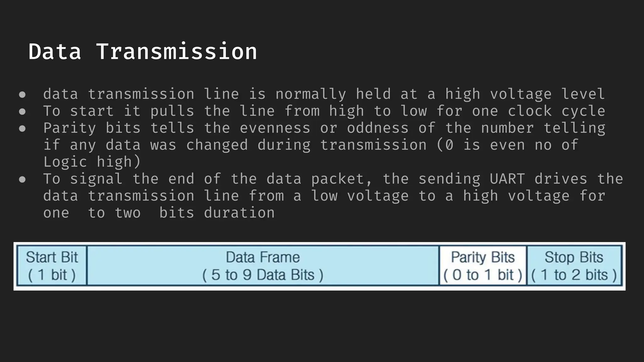
Data Transmission
● datatransmission line is normally held at a high voltage level
● To start it pulls the line from high to low for one clock cycle
● Parity bits tells the evenness or oddness of the number telling
if any data was changed during transmission (0 is even no of
Logic high)
● To signal the end of the data packet, the sending UART drives the
data transmission line from a low voltage to a high voltage for
one to two bits duration
10.
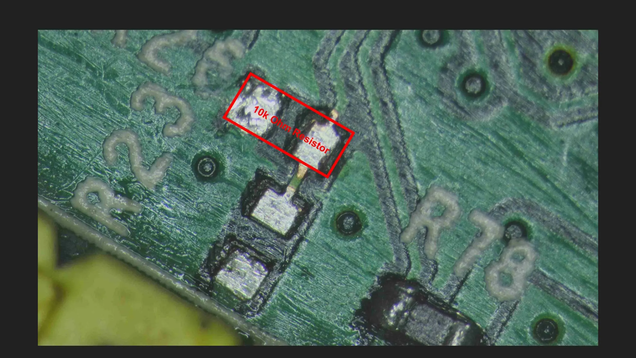
Step 0 :Opening the device &
visual ID of candidate pins
11.
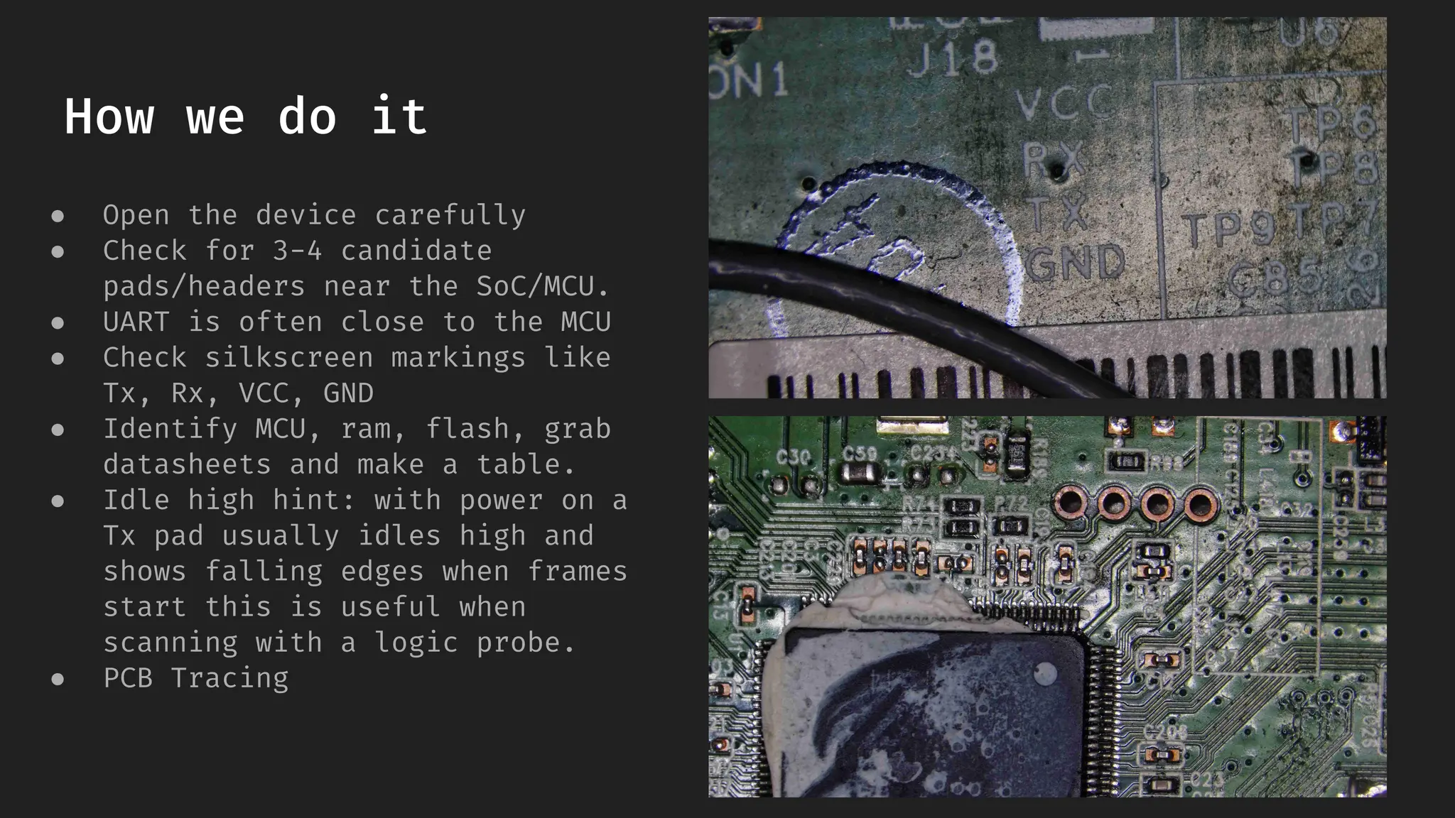
How we doit
● Open the device carefully
● Check for 3-4 candidate
pads/headers near the SoC/MCU.
● UART is often close to the MCU
● Check silkscreen markings like
Tx, Rx, VCC, GND
● Identify MCU, ram, flash, grab
datasheets and make a table.
● Idle high hint: with power on a
Tx pad usually idles high and
shows falling edges when frames
start this is useful when
scanning with a logic probe.
● PCB Tracing
12.
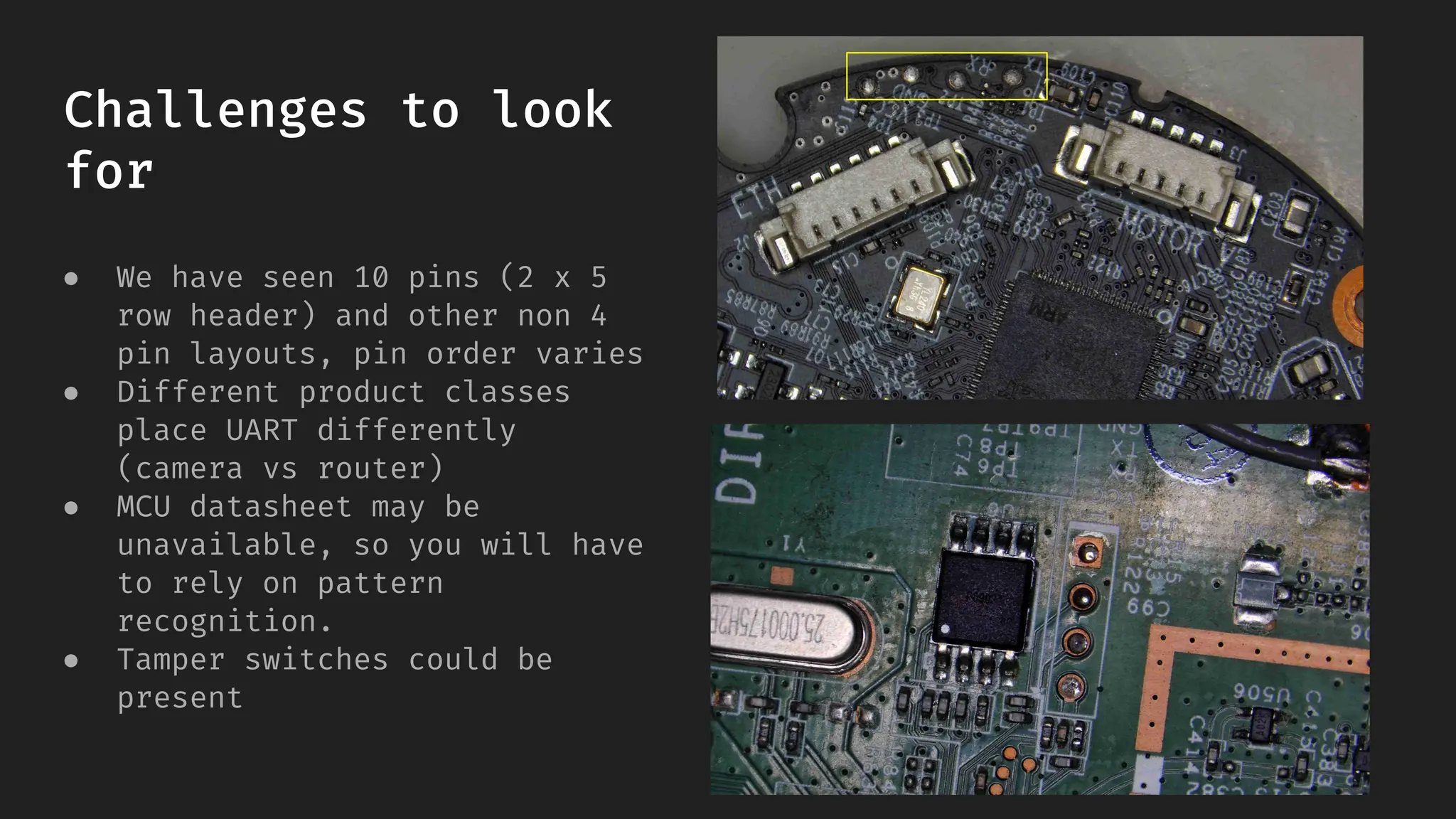
Challenges to look
for
●We have seen 10 pins (2 x 5
row header) and other non 4
pin layouts, pin order varies
● Different product classes
place UART differently
(camera vs router)
● MCU datasheet may be
unavailable, so you will have
to rely on pattern
recognition.
● Tamper switches could be
present
13.
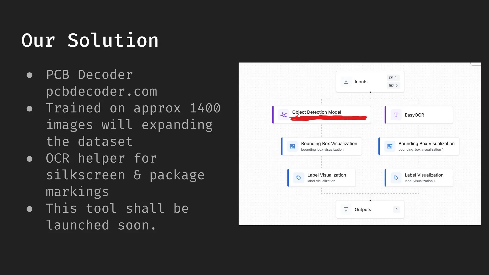
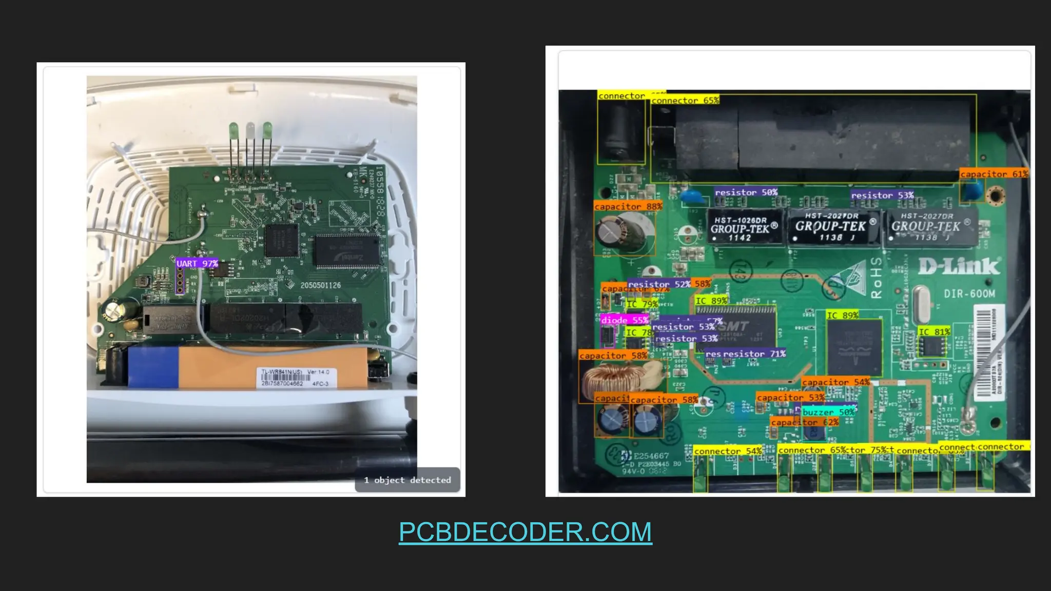
Our Solution
● PCBDecoder
pcbdecoder.com
● Trained on approx 1400
images will expanding
the dataset
● OCR helper for
silkscreen & package
markings
● This tool shall be
launched soon.
How we doit
● Use a multimeter for GND identification (continuity to
chassis/large ground pours)
● If you can find VCC note it but do not connect
● Voltage fluctuating hints at Tx but is not definitive
● Power cycle and observe candidate pins
● Prefer a logic analyzer/scope and enable a UART/Async
Serial decoder.
● UART idles high, it shows a steady high with low pulses
on frames
18.
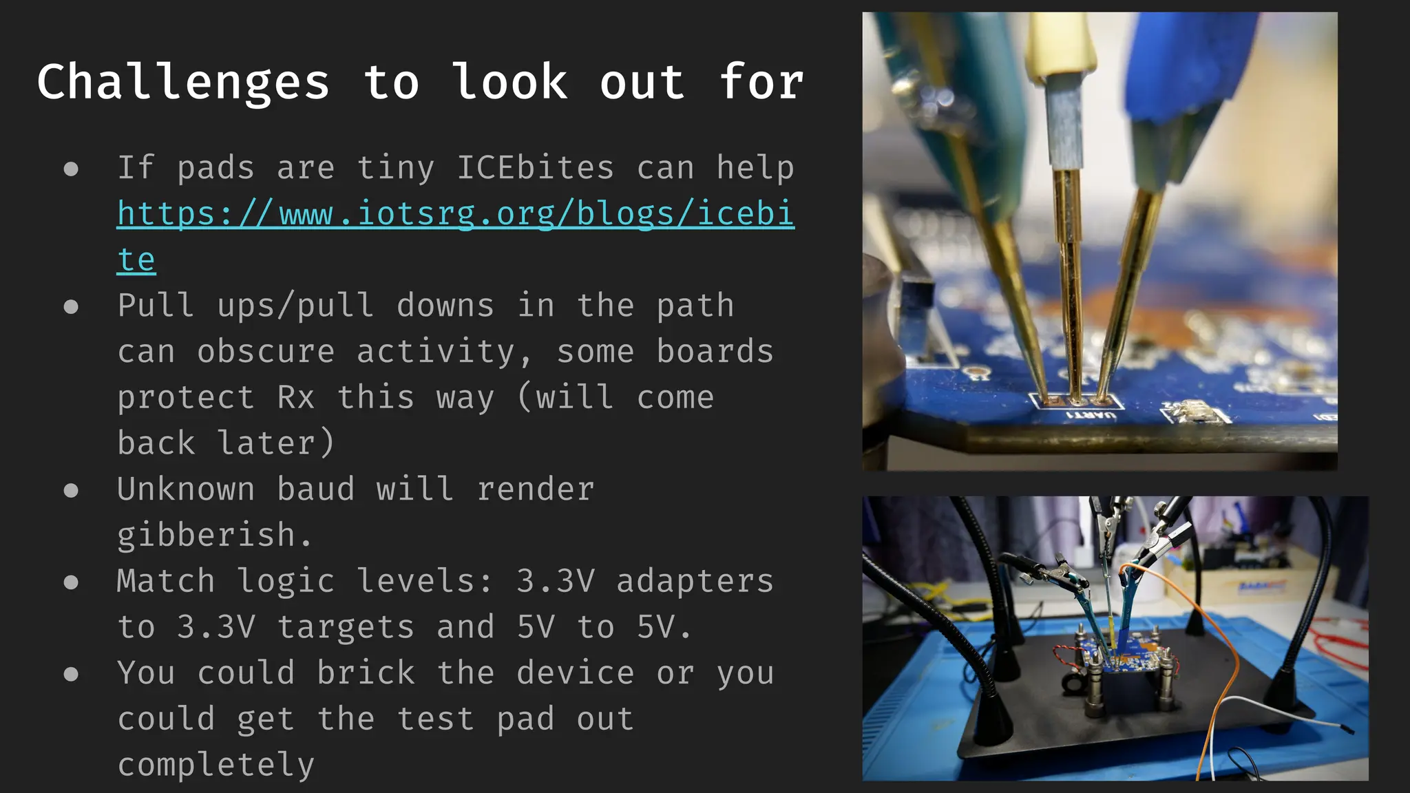
Challenges to lookout for
● If pads are tiny ICEbites can help
https://www.iotsrg.org/blogs/icebi
te
● Pull ups/pull downs in the path
can obscure activity, some boards
protect Rx this way (will come
back later)
● Unknown baud will render
gibberish.
● Match logic levels: 3.3V adapters
to 3.3V targets and 5V to 5V.
● You could brick the device or you
could get the test pad out
completely
19.
Our Solution
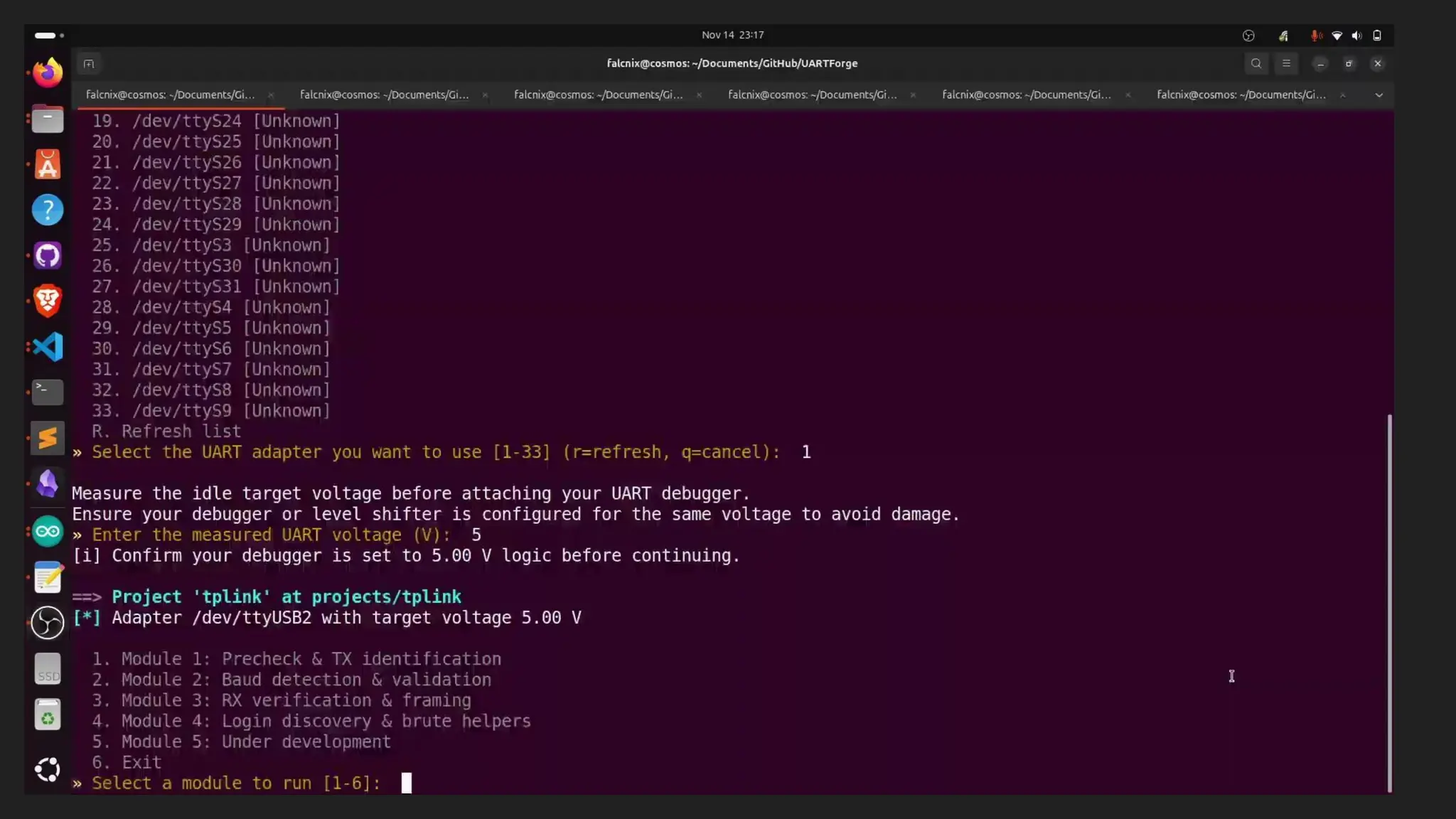
● Thetool passively listens at a configurable baud sweep, looking for UART
activity (printable characters)
● For each baud we counts bytes, printable ratios and produces an ASCII
preview
● We save this into a session file
How we doit
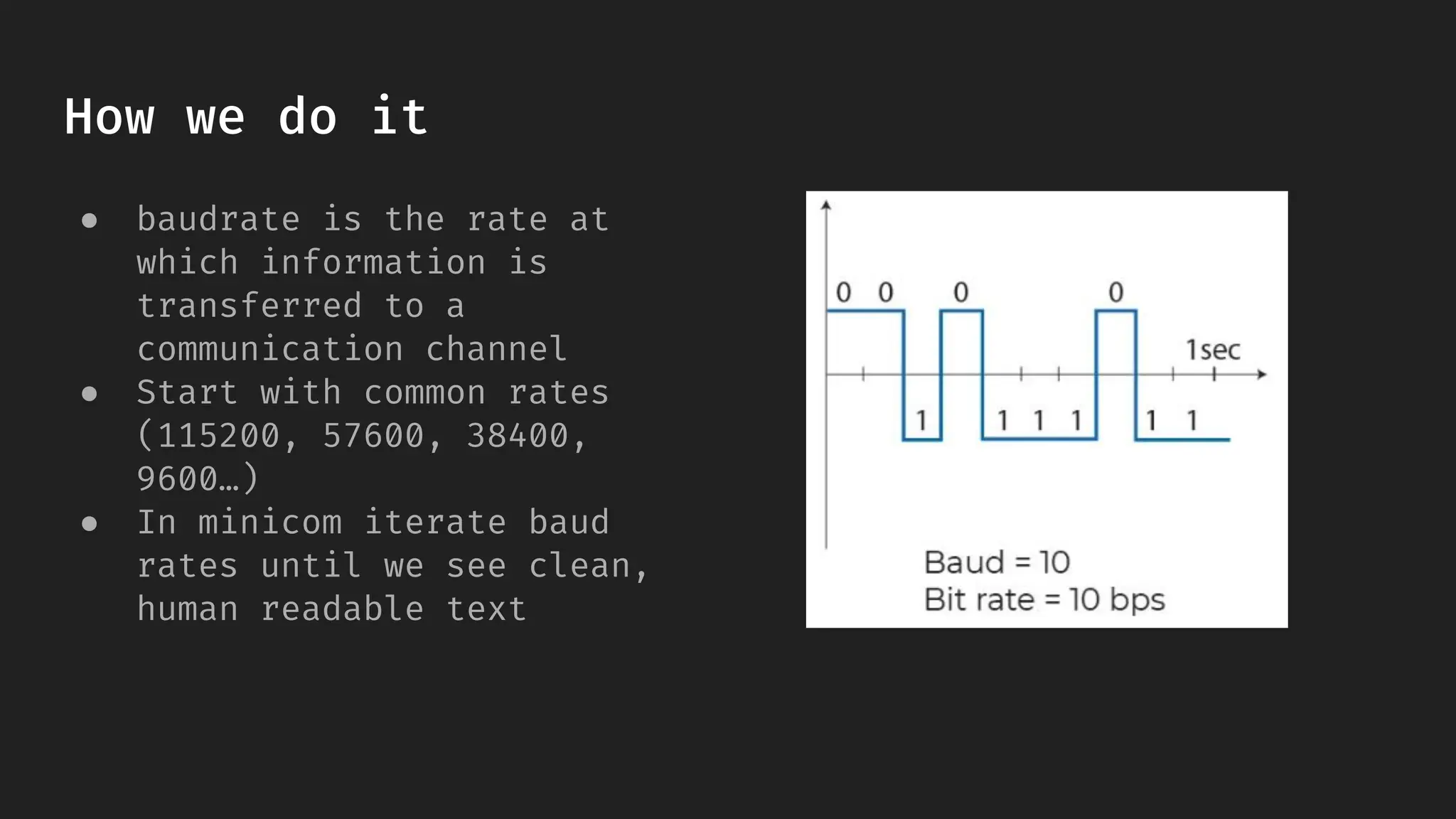
● baudrate is the rate at
which information is
transferred to a
communication channel
● Start with common rates
(115200, 57600, 38400,
9600…)
● In minicom iterate baud
rates until we see clean,
human readable text
23.
Challenges to lookout for
● OEMs sometimes change defaults so dont assume
115200/9600.
● Inverted lines or non-8N1 framing can mimic noise
24.
Our Solution
● Withidentified RX it tries a set of baud rate
● Two modes full and turbo
● For every baudrate it counts total bytes and how many look like printable
ASCII
● Printable ratio is calculated by dividing printable bytes by total bytes received
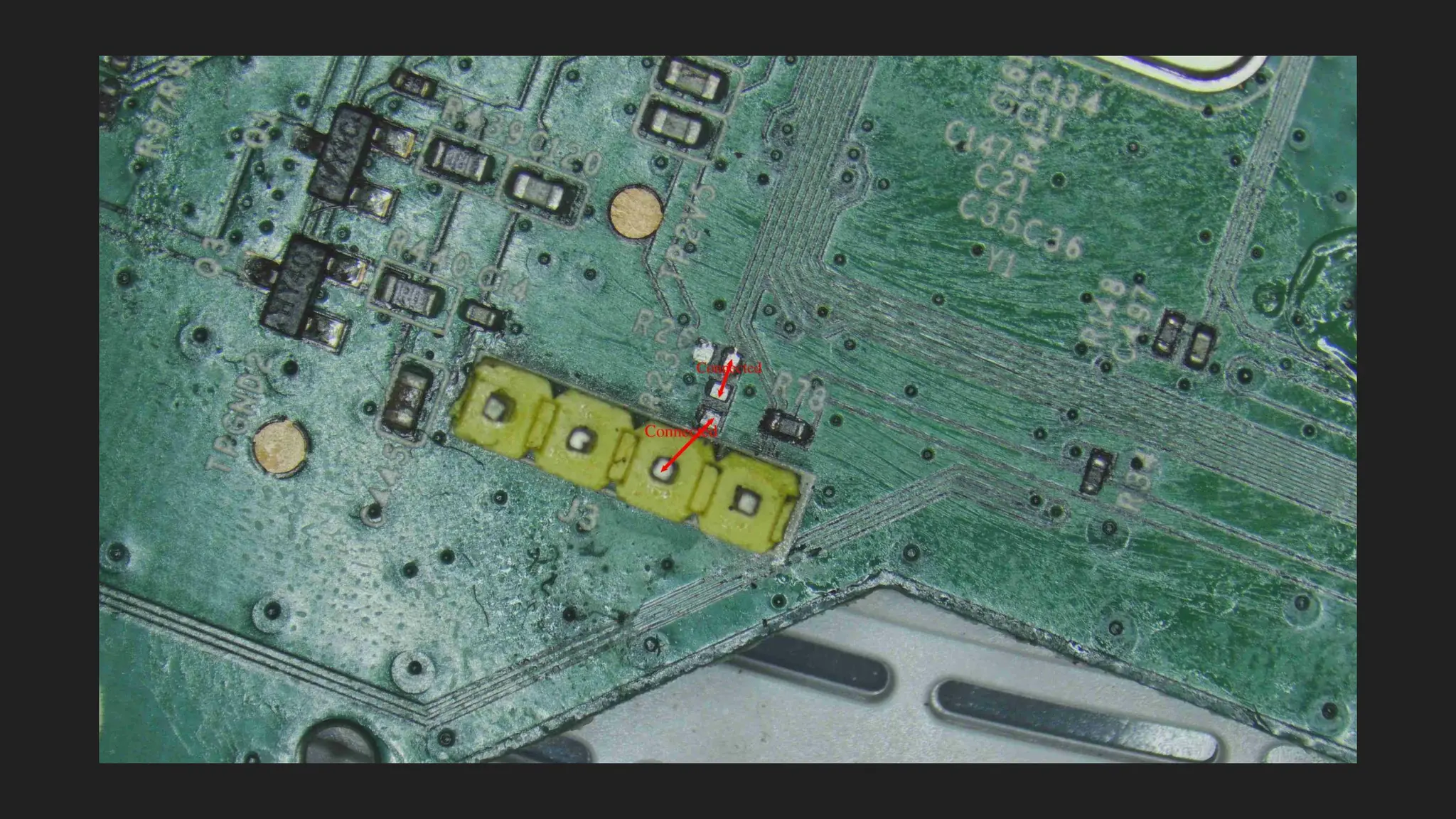
How we doit
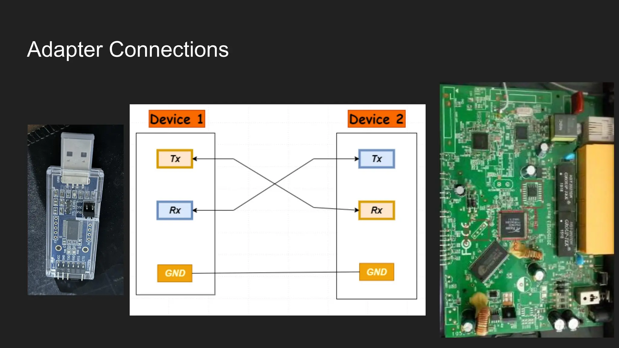
● By now we have got Tx and baudrate
● Connect Tx (adapter) to Rx (target) to test input
● Ensure terminal framing matches (e.g. 8N1) or parsing
will be wrong
● 8N1 = 8 data bits , no parity bit 1 and one stop bit
28.
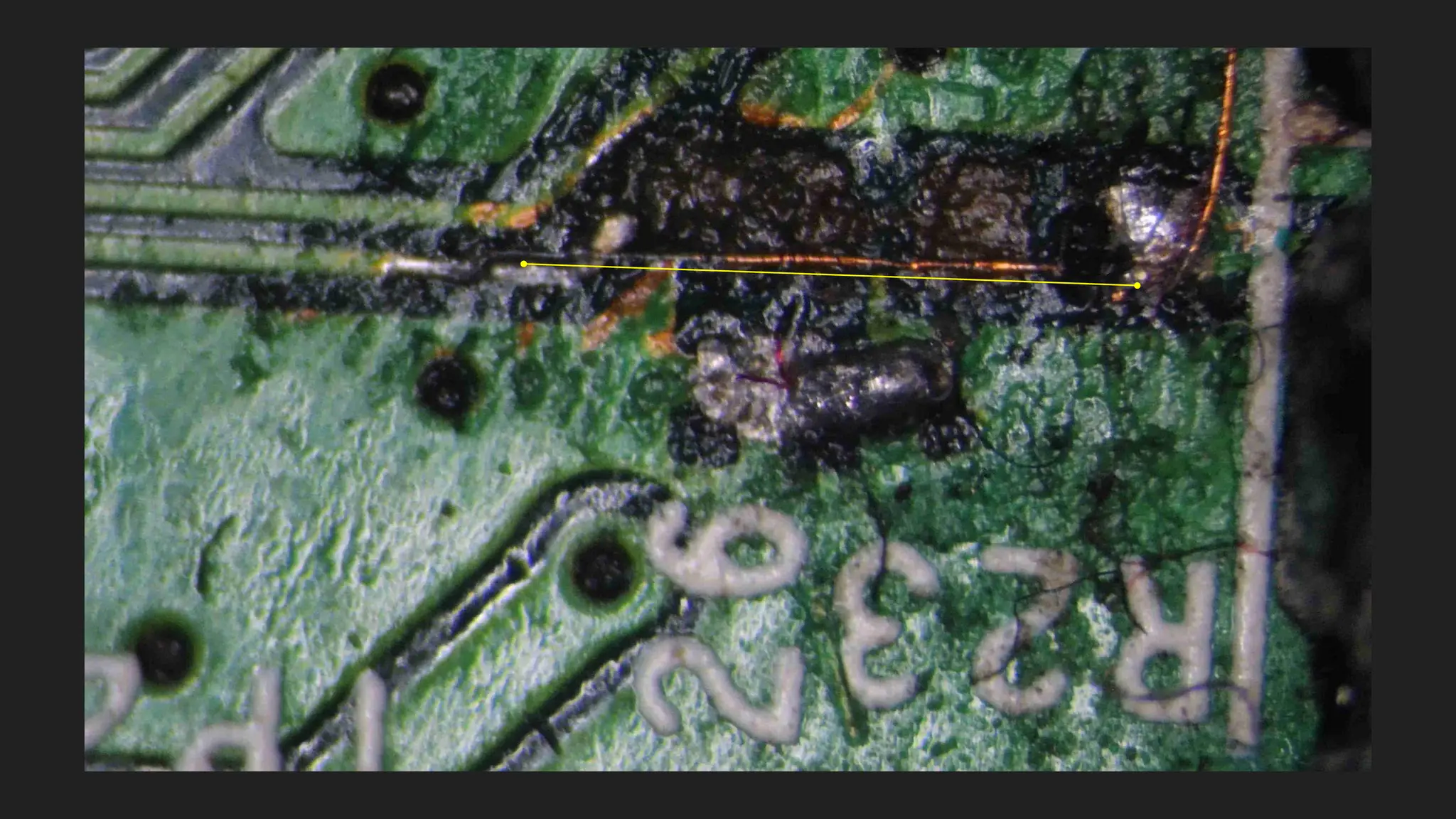
Challenges to lookout for
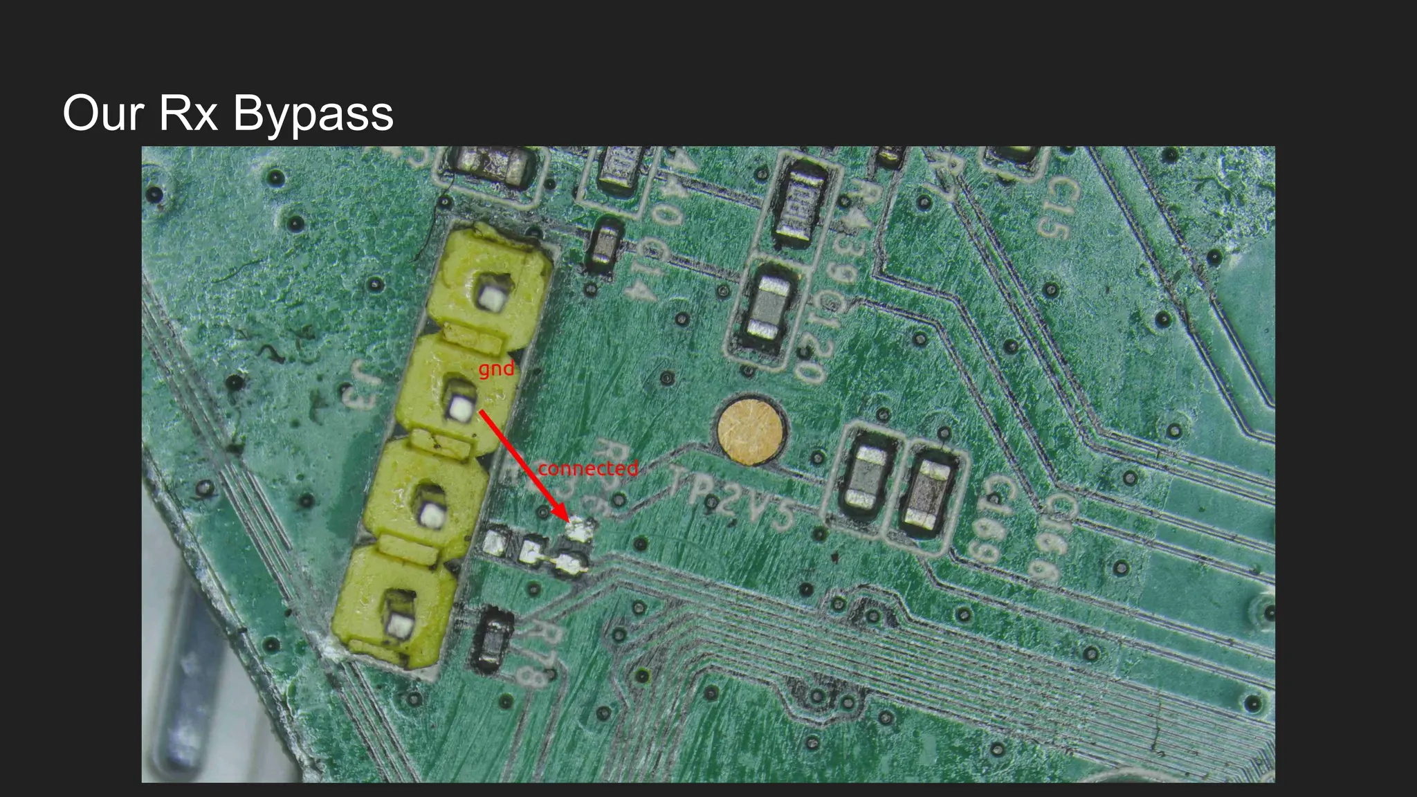
● You may not be able to send data (series resistors/pull networks in path);
micro rework/jumpers may be required
● Might need expensive tools like microscope, fine tip iron, thin
jumpers(0.007mm)
● Unknown baud/parity/stop could noisy captures
Our Solution
● Withknown baud rate and from module 2 and Tx(target device) from module
1
● We deliberately send small test messages over UART to provoke a response
from the target
● It sends a fixed sequence of test tokens: r, n, rn, U, ., helprn.
● It captures all bytes that come back during each stimulus window and
correlates the output from the input given.
How we doit
● Try documented service accounts or vendor-provided
recovery creds first.
● If a login prompt appears, observe behavior (lockouts,
banners) and record responsibly.
36.
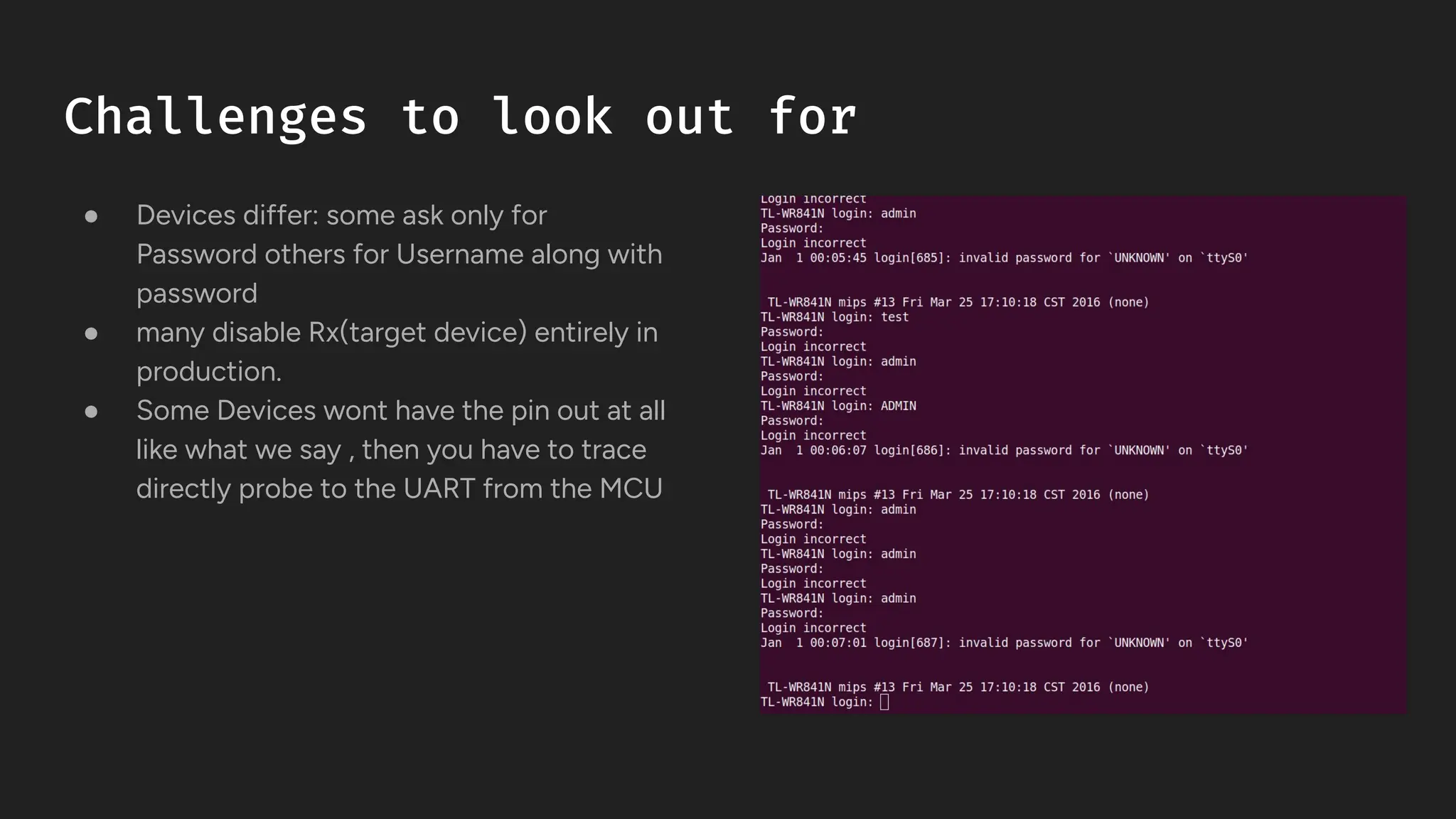
Challenges to lookout for
● Devices differ: some ask only for
Password others for Username along with
password
● many disable Rx(target device) entirely in
production.
● Some Devices wont have the pin out at all
like what we say , then you have to trace
directly probe to the UART from the MCU
37.
Our Solution
● Withrunning Modules 1-3 we have Rx, Tx and Baudrate and with this we spin
the minicom shell
● Identify the parameters to fuzz
● We have certain success and failed attempt regex
● We have wake sequences this mimic you pressing enter and space button as
sometime only when you press this is where you get the login enquiry
● Multi parameter fuzz still needs to be worked on
41.
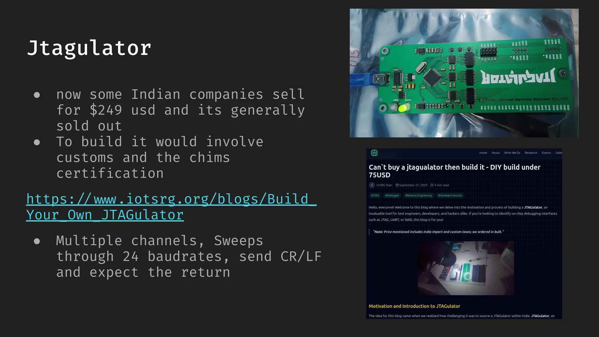
Jtagulator
● now someIndian companies sell
for $249 usd and its generally
sold out
● To build it would involve
customs and the chims
certification
https://www.iotsrg.org/blogs/Build_
Your_Own_JTAGulator
● Multiple channels, Sweeps
through 24 baudrates, send CR/LF
and expect the return
42.
Our Tool
● Hardwareindependent , any adapter can be used
● Entire logic is on the host
● We focus on the Printable Ratio
● It’s quite Cheap
- Baulowl (ourown tool)
- baudrate.py - legend tool by -
https://github.com/devttys0
- Jtagulator by Joe Grand
Credits to other projects that we took
inspiration from