What is UART?
•Point to point serial interface on many
‑ ‑
MCUs/SoCs
• Asynchronous: no separate clock; both ends
agree on timing (baud rate)
• Typical uses
– debug console, GPS, Bluetooth modules (HC 05),
‑
sensors, modems
• Full duplex on two wires: TX and RX (+ GND)
3.
Signal Levels
• TTL/CMOSlogic
– 0–3.3 V or 0–5 V (MCU pins), idle HIGH
• RS 232
‑
– ±3…±12 V, inverted logic, needs level shifter
(MAX3232)
• RS 485/422
‑
– Differential pair for long distance / multi drop
‑
4.
Frame Format
• Startbit (LOW)
• 5–9 data bits (LSB first)
• Optional parity: None/Even/Odd
• 1–2 stop bits (HIGH)
• Common shorthand: 8 N 1, 7 E 1, etc.
‑ ‑ ‑ ‑
5.
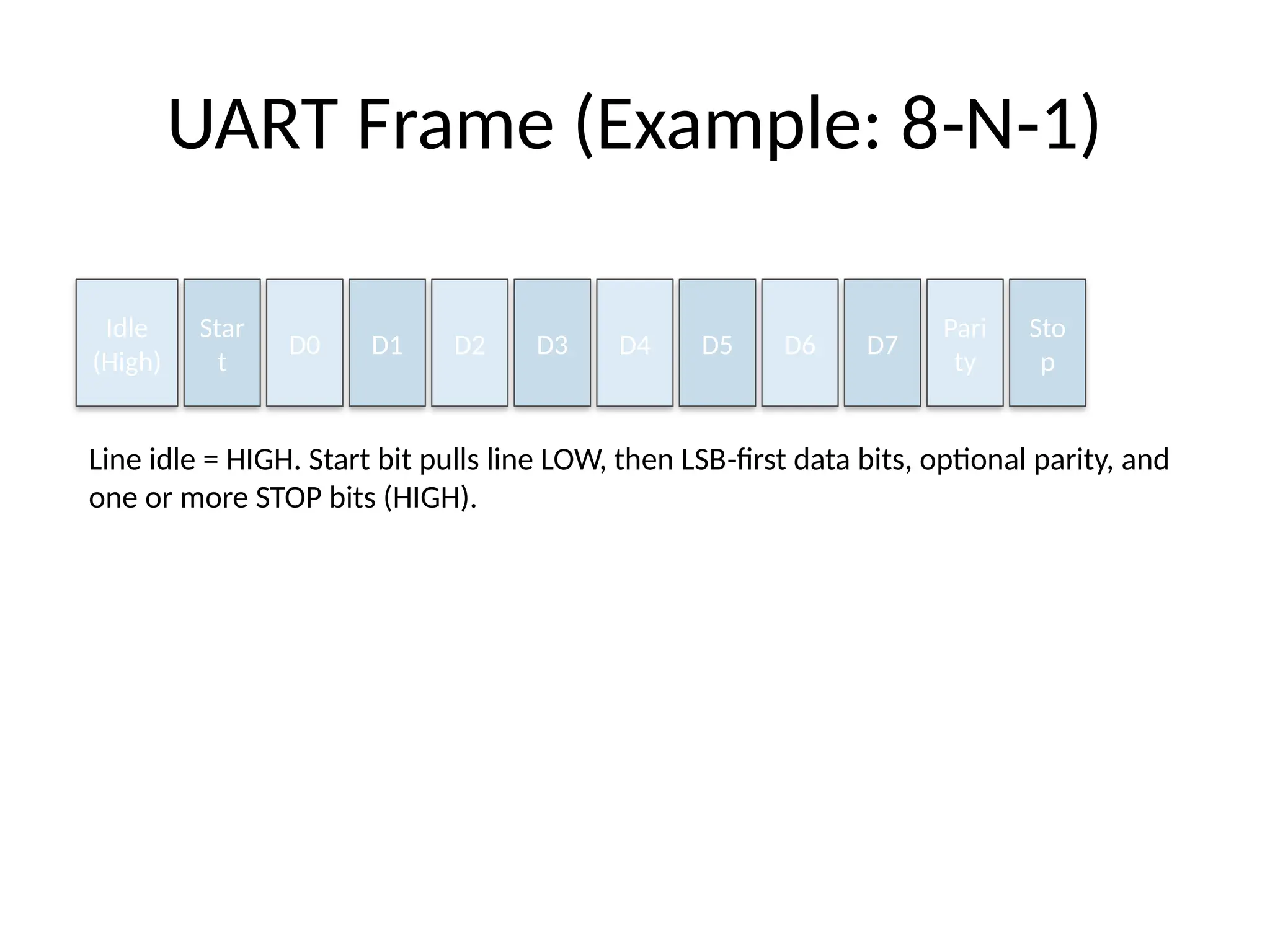
UART Frame (Example:8 N 1)
‑ ‑
Idle
(High)
Star
t
D0 D1 D2 D3 D4 D5 D6 D7
Pari
ty
Sto
p
Line idle = HIGH. Start bit pulls line LOW, then LSB first data bits, optional parity, and
‑
one or more STOP bits (HIGH).
6.
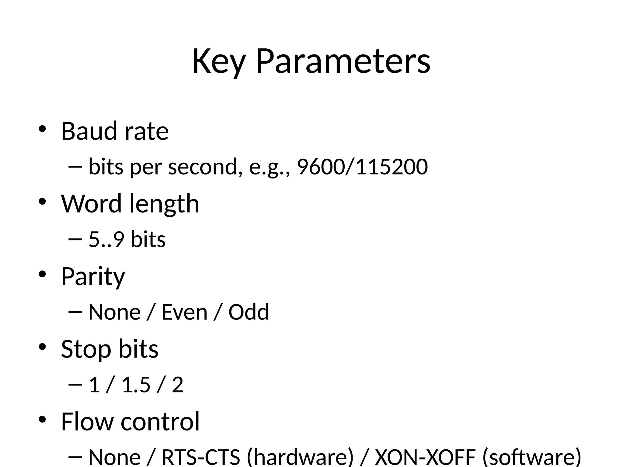
Key Parameters
• Baudrate
– bits per second, e.g., 9600/115200
• Word length
– 5..9 bits
• Parity
– None / Even / Odd
• Stop bits
– 1 / 1.5 / 2
• Flow control
– None / RTS CTS (hardware) / XON XOFF (software)
‑ ‑
7.
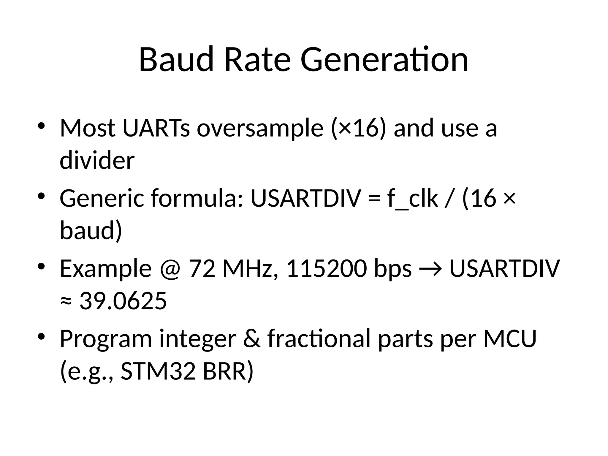
Baud Rate Generation
•Most UARTs oversample (×16) and use a
divider
• Generic formula: USARTDIV = f_clk / (16 ×
baud)
• Example @ 72 MHz, 115200 bps → USARTDIV
≈ 39.0625
• Program integer & fractional parts per MCU
(e.g., STM32 BRR)
8.
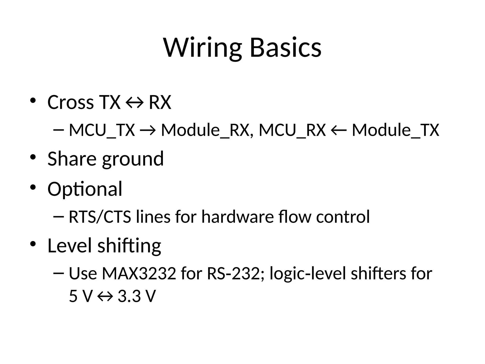
Wiring Basics
• CrossTX↔RX
– MCU_TX → Module_RX, MCU_RX ← Module_TX
• Share ground
• Optional
– RTS/CTS lines for hardware flow control
• Level shifting
– Use MAX3232 for RS 232; logic level shifters for
‑ ‑
5 V↔3.3 V
9.
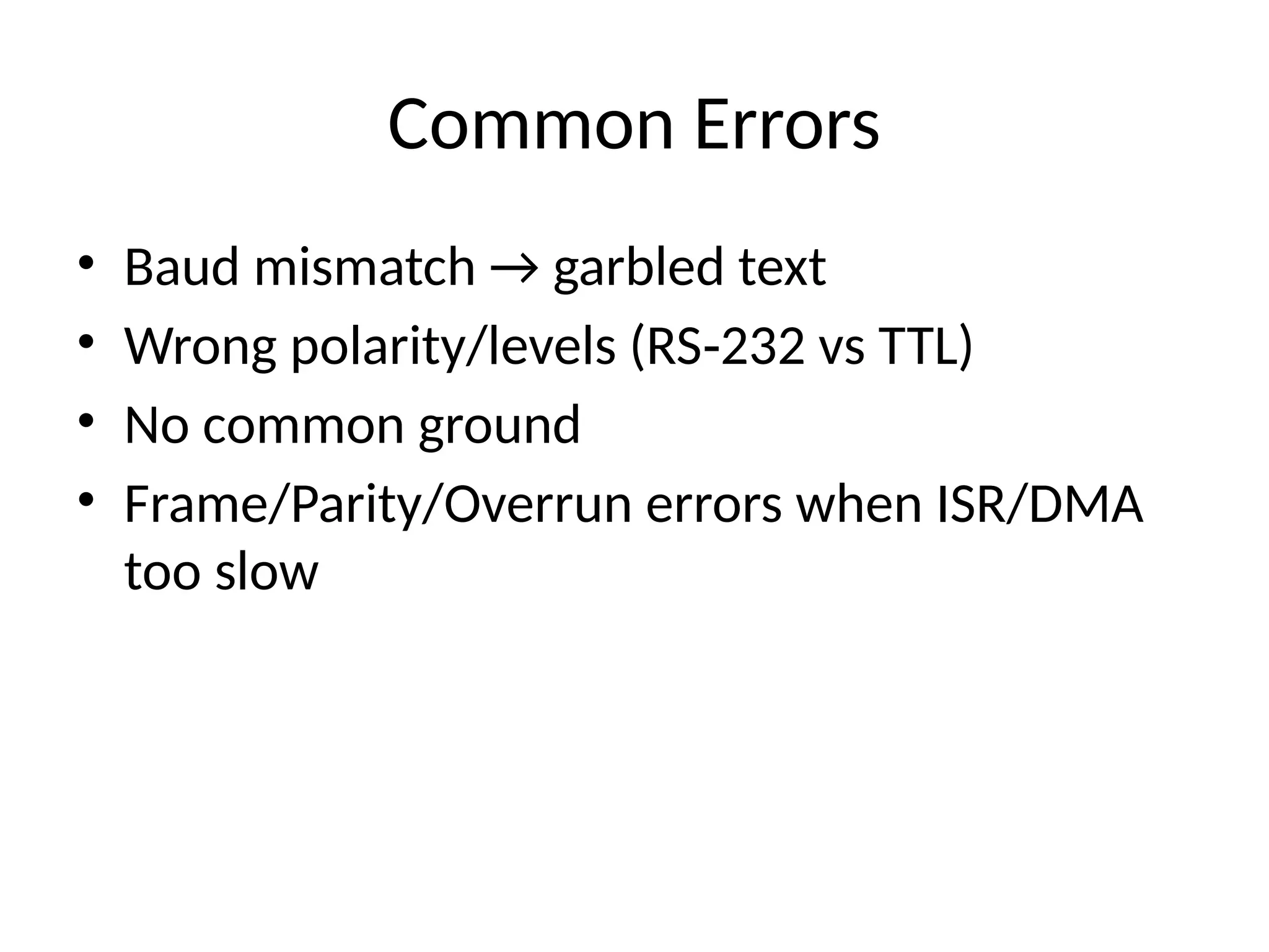
Common Errors
• Baudmismatch → garbled text
• Wrong polarity/levels (RS 232 vs TTL)
‑
• No common ground
• Frame/Parity/Overrun errors when ISR/DMA
too slow
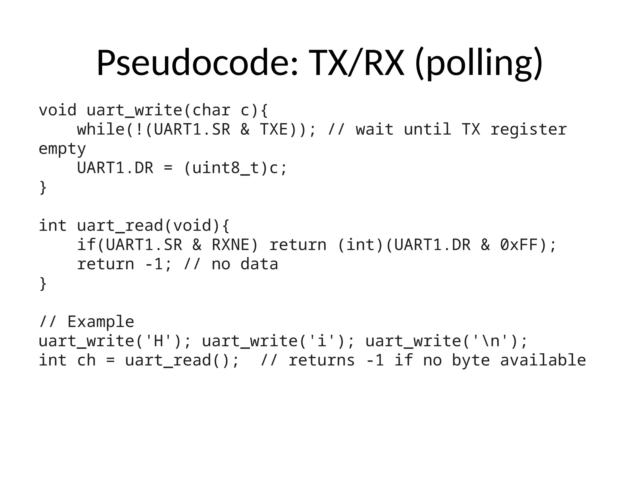
Pseudocode: TX/RX (polling)
voiduart_write(char c){
while(!(UART1.SR & TXE)); // wait until TX register
empty
UART1.DR = (uint8_t)c;
}
int uart_read(void){
if(UART1.SR & RXNE) return (int)(UART1.DR & 0xFF);
return -1; // no data
}
// Example
uart_write('H'); uart_write('i'); uart_write('n');
int ch = uart_read(); // returns -1 if no byte available
13.
Interrupt/DMA
• RX interruptfor low latency byte capture
‑
• DMA for high throughput with ring buffers
• Use timeouts or delimiters to frame packets
14.
Simple Packet Design
•Add header (e.g., 0x55), length, payload,
checksum/CRC
• Escape special bytes or use SLIP/COBS framing
• Validate checksum before processing
15.
RS 485 Notes(Multi drop)
‑ ‑
• Half duplex on differential pair A/B
‑
• Transceiver DE/RE pin to switch TX/RX
• 120 Ω termination at both ends; bias resistors
to define idle state
• Use addressing in your packet format
16.
Debugging Tips
• Startat 9600 8 N 1; echo characters to verify
‑ ‑
link
• Use a USB UART dongle + terminal
‑
(PuTTY/minicom)
• Check with logic analyzer/oscilloscope
• Print status flags when things go wrong
17.
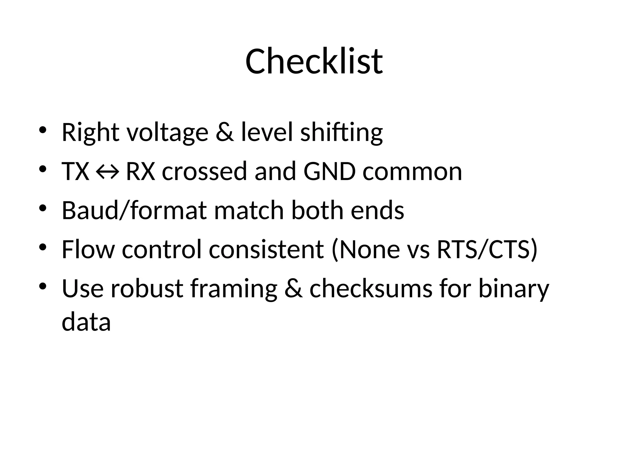
Checklist
• Right voltage& level shifting
• TX↔RX crossed and GND common
• Baud/format match both ends
• Flow control consistent (None vs RTS/CTS)
• Use robust framing & checksums for binary
data
Editor's Notes
#3 Match voltage domains; never connect RS‑232 directly to MCU pins.
#11 Use your MCU reference manual for exact register names.