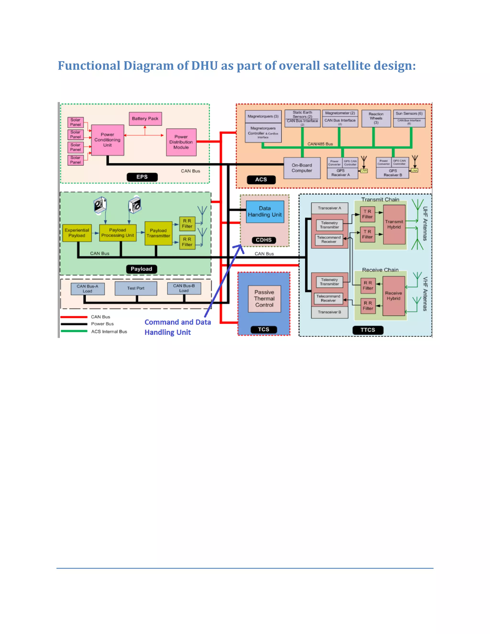
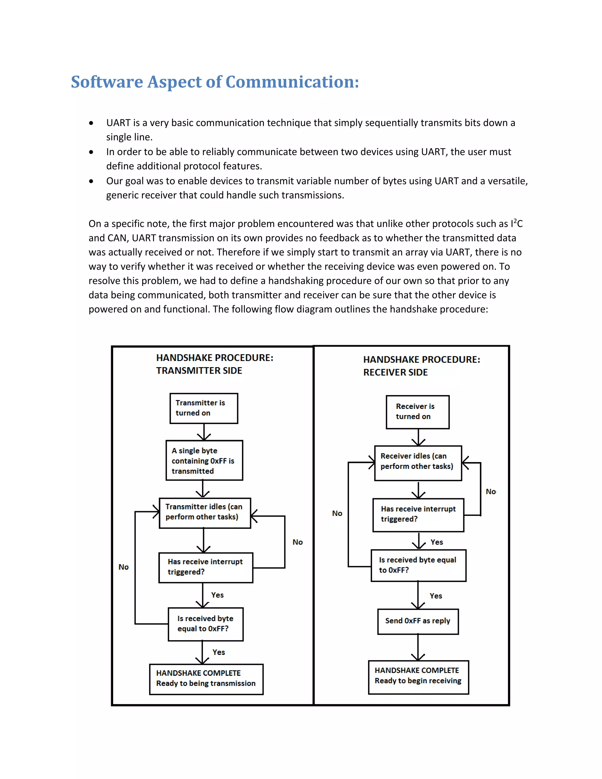
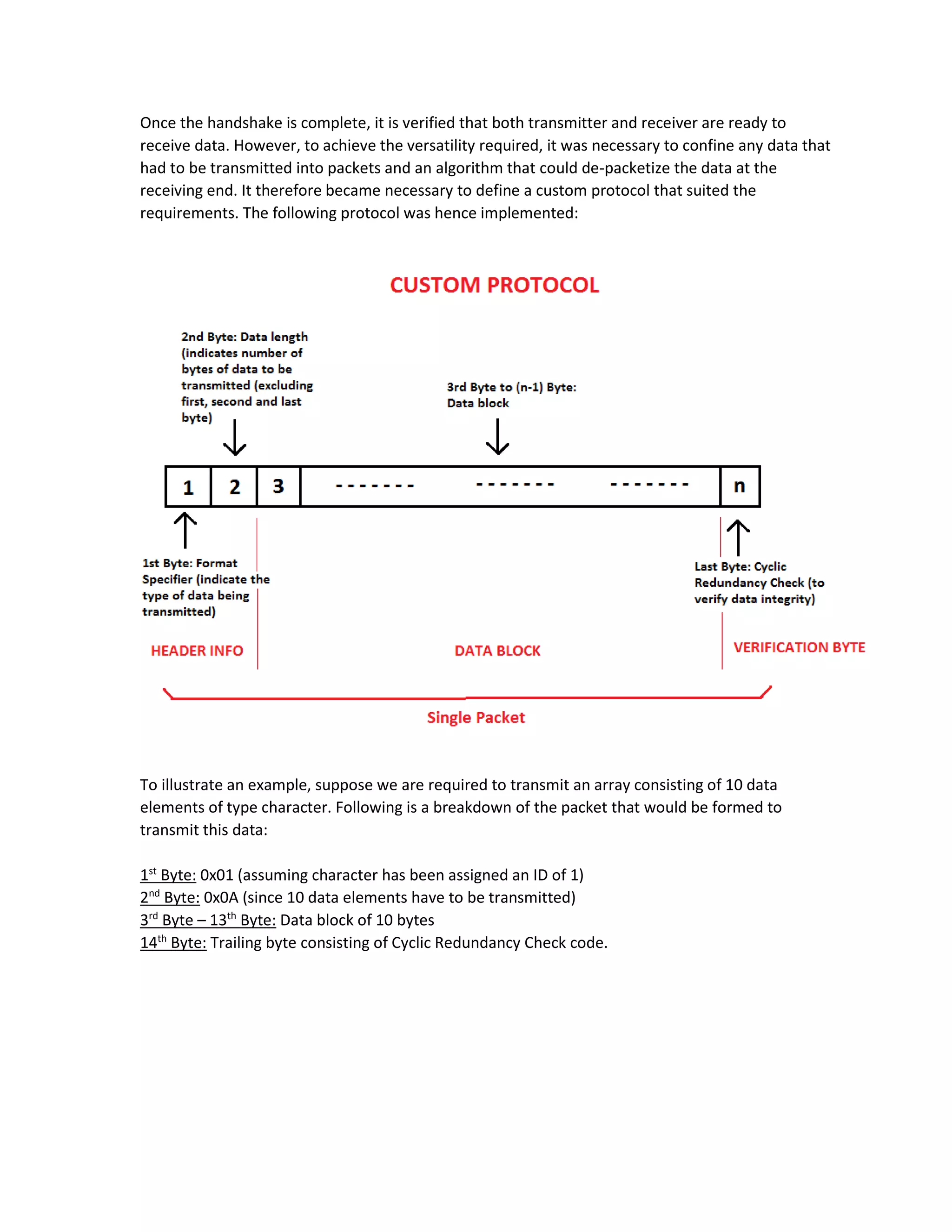
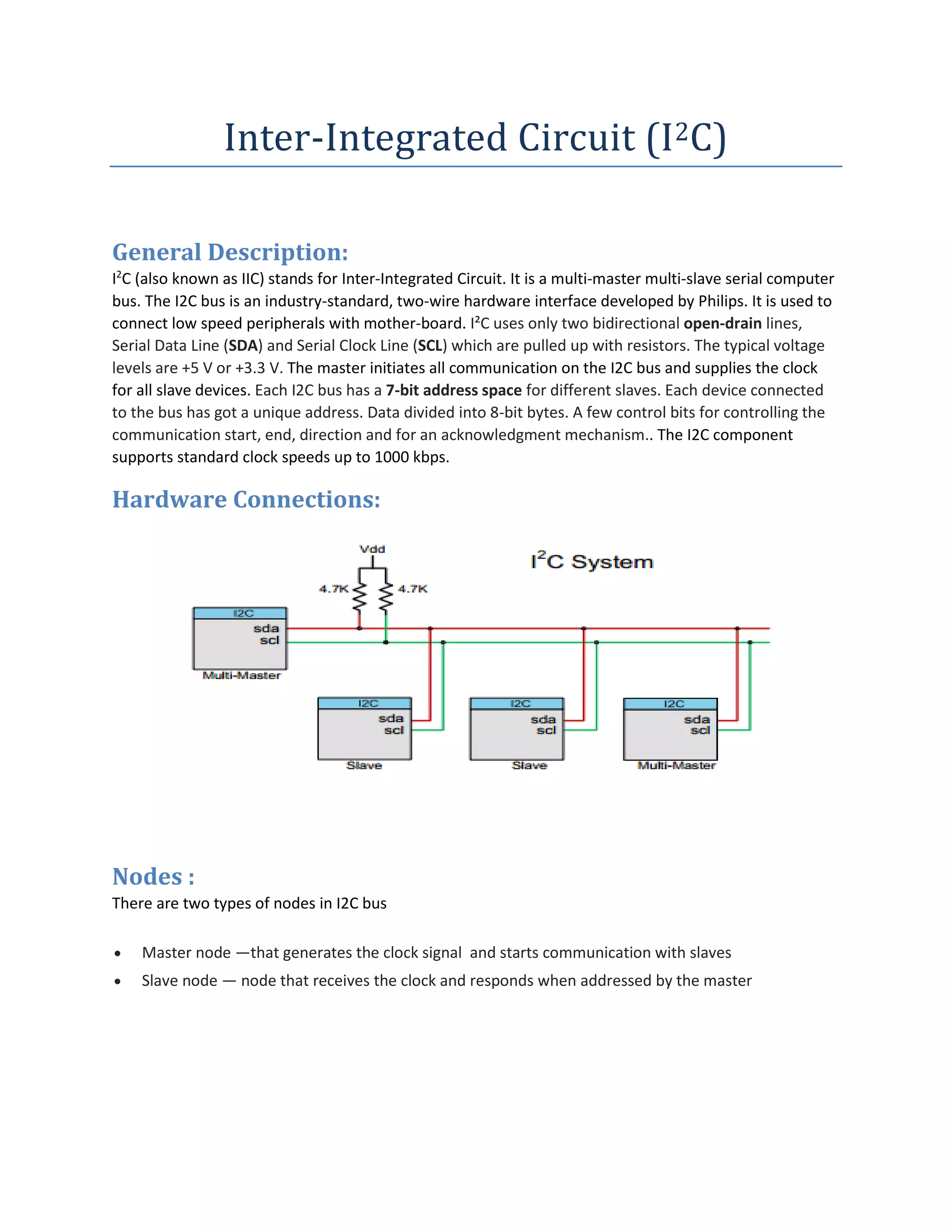
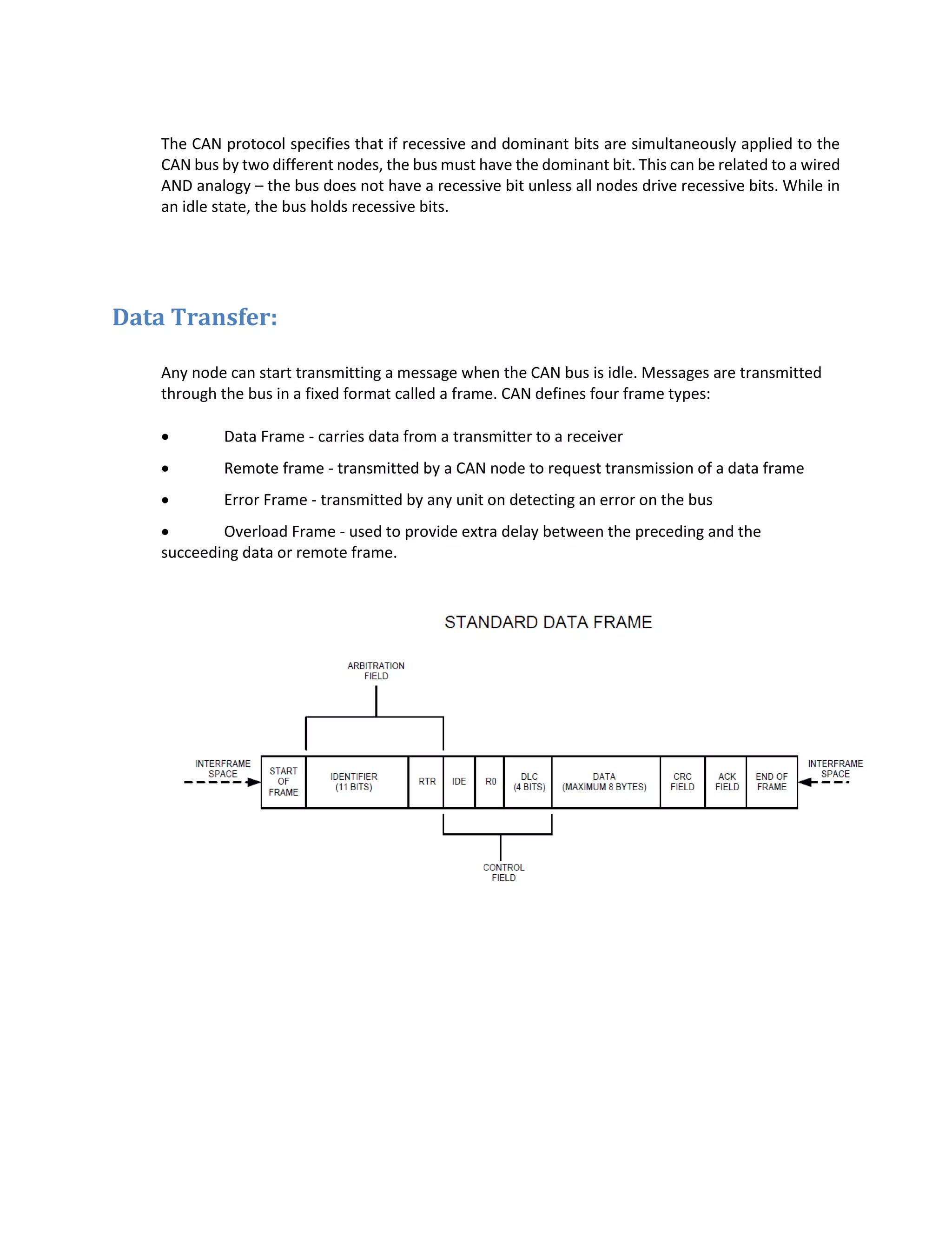
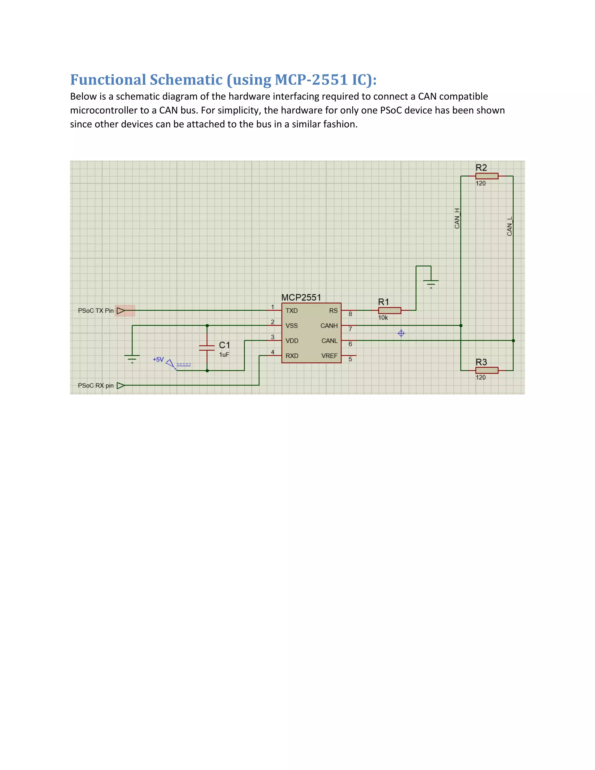
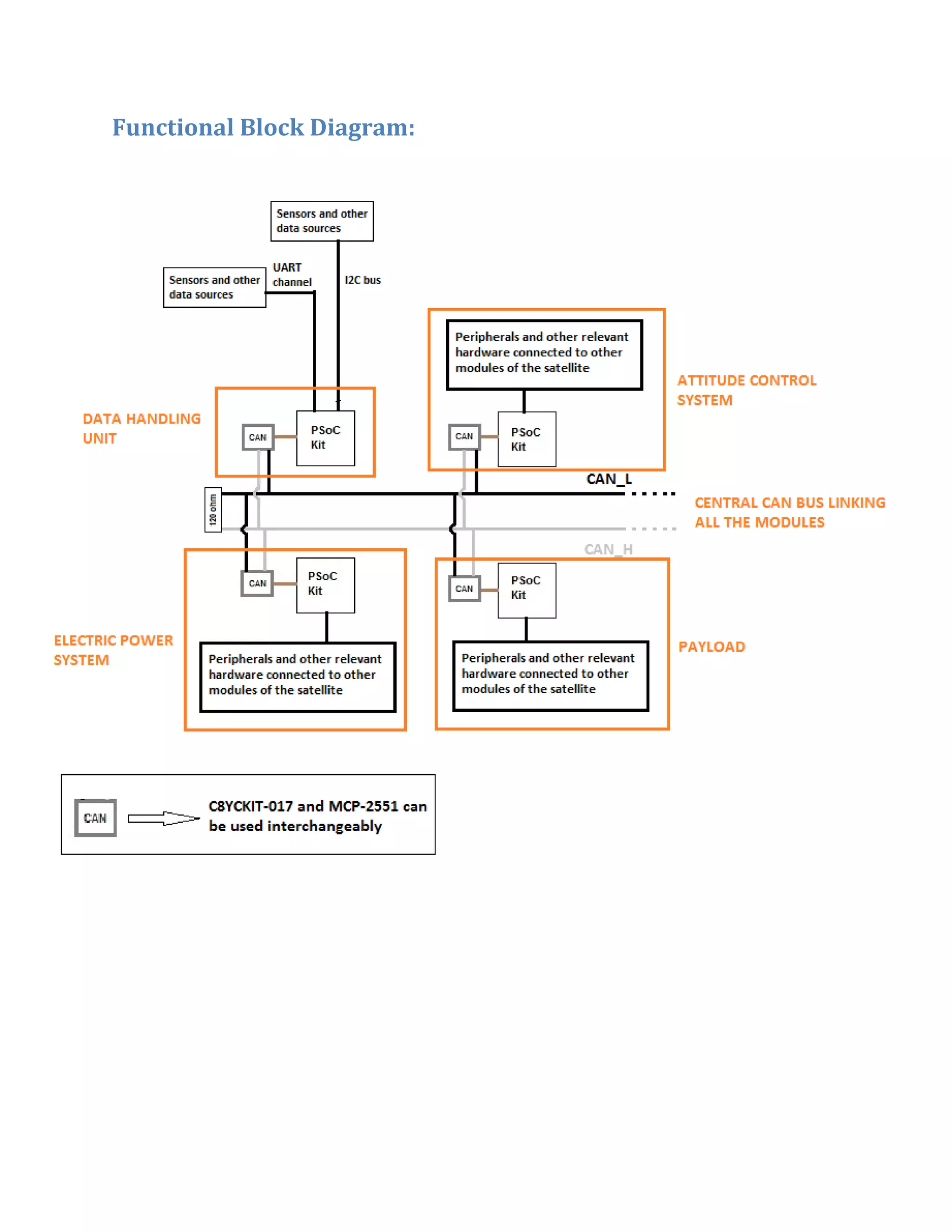
The document describes a Data Handling Unit (DHU) for a satellite. The DHU controls information flow between satellite modules and the ground station. It receives and distributes commands, acquires and processes telemetry from subsystems, and performs health monitoring. The DHU uses CCSDS packetization for telemetry and depacketization of commands. It also generates timing signals and performs bus management autonomously. The document includes a functional diagram of the DHU and describes its use of UART communication between modules using a custom protocol that includes handshaking and CRC error checking. Code examples in C show the implementation of the UART receiver and transmitter on a PSoC microcontroller.

![uint8 _CRCbyte = 0;
uint8 dataBlock[10];
uint8 CRC;
code unsigned char crc8_table[] = {
0x00, 0x3e, 0x7c, 0x42, 0xf8, 0xc6, 0x84, 0xba, 0x95, 0xab, 0xe9,
0xd7,
0x6d, 0x53, 0x11, 0x2f, 0x4f, 0x71, 0x33, 0x0d, 0xb7, 0x89, 0xcb,
0xf5,
0xda, 0xe4, 0xa6, 0x98, 0x22, 0x1c, 0x5e, 0x60, 0x9e, 0xa0, 0xe2,
0xdc,
0x66, 0x58, 0x1a, 0x24, 0x0b, 0x35, 0x77, 0x49, 0xf3, 0xcd, 0x8f,
0xb1,
0xd1, 0xef, 0xad, 0x93, 0x29, 0x17, 0x55, 0x6b, 0x44, 0x7a, 0x38,
0x06,
0xbc, 0x82, 0xc0, 0xfe, 0x59, 0x67, 0x25, 0x1b, 0xa1, 0x9f, 0xdd,
0xe3,
0xcc, 0xf2, 0xb0, 0x8e, 0x34, 0x0a, 0x48, 0x76, 0x16, 0x28, 0x6a,
0x54,
0xee, 0xd0, 0x92, 0xac, 0x83, 0xbd, 0xff, 0xc1, 0x7b, 0x45, 0x07,
0x39,
0xc7, 0xf9, 0xbb, 0x85, 0x3f, 0x01, 0x43, 0x7d, 0x52, 0x6c, 0x2e,
0x10,
0xaa, 0x94, 0xd6, 0xe8, 0x88, 0xb6, 0xf4, 0xca, 0x70, 0x4e, 0x0c,
0x32,
0x1d, 0x23, 0x61, 0x5f, 0xe5, 0xdb, 0x99, 0xa7, 0xb2, 0x8c, 0xce,
0xf0,
0x4a, 0x74, 0x36, 0x08, 0x27, 0x19, 0x5b, 0x65, 0xdf, 0xe1, 0xa3,
0x9d,
0xfd, 0xc3, 0x81, 0xbf, 0x05, 0x3b, 0x79, 0x47, 0x68, 0x56, 0x14,
0x2a,
0x90, 0xae, 0xec, 0xd2, 0x2c, 0x12, 0x50, 0x6e, 0xd4, 0xea, 0xa8,
0x96,
0xb9, 0x87, 0xc5, 0xfb, 0x41, 0x7f, 0x3d, 0x03, 0x63, 0x5d, 0x1f,
0x21,
0x9b, 0xa5, 0xe7, 0xd9, 0xf6, 0xc8, 0x8a, 0xb4, 0x0e, 0x30, 0x72,
0x4c,](https://image.slidesharecdn.com/9b3bbdc5-1ab0-49f4-a71a-e0bef009c45e-160421173910/75/Final-Report-9-2048.jpg)
![crc = crc & 1 ? (crc >> 1) ^ POLY : crc >> 1;
crc = crc & 1 ? (crc >> 1) ^ POLY : crc >> 1;
crc = crc & 1 ? (crc >> 1) ^ POLY : crc >> 1;
crc = crc & 1 ? (crc >> 1) ^ POLY : crc >> 1;
crc = crc & 1 ? (crc >> 1) ^ POLY : crc >> 1;
crc = crc & 1 ? (crc >> 1) ^ POLY : crc >> 1;
} while (dataBlock < end);
return crc ^ 0xff;
}
void printArray()
{
LCD_Char_1_Position(0u, 0u);
LCD_Char_1_PrintHexUint8(dataBlock[0]);
LCD_Char_1_PrintHexUint8(dataBlock[1]);
LCD_Char_1_PrintHexUint8(CRC);
LCD_Char_1_Position(1u, 0u);
for(i=2; i<dataBlock[1]+2; i++)
{
LCD_Char_1_PrintHexUint8(dataBlock[i]);
}
}
int main()
{
UART_1_Start();
LCD_Char_1_Start();
initHandshake();
for(;;)
{
}](https://image.slidesharecdn.com/9b3bbdc5-1ab0-49f4-a71a-e0bef009c45e-160421173910/75/Final-Report-11-2048.jpg)
![}
void TX_ISR()
{
return;
}
void RX_ISR()
{
if (!isHSDone)
{
handshake_byte = UART_1_GetByte();
if (handshake_byte == HANDSHAKE_VAR)
UART_1_PutChar(HANDSHAKE_VAR);
isHSDone = 1;
_formatSpecifier = 1;
return;
}
else if (_formatSpecifier)
{
dataBlock[i] = UART_1_GetChar();
i++;
_formatSpecifier = 0;
_packetSize = 1;
}
else if (_packetSize)
{
dataBlock[i] = UART_1_GetChar();
i++;
_packetSize = 0;
_blockData = 1;
}](https://image.slidesharecdn.com/9b3bbdc5-1ab0-49f4-a71a-e0bef009c45e-160421173910/75/Final-Report-12-2048.jpg)
![else if (_blockData)
{
dataBlock[i] = UART_1_GetChar();
i++;
if (i == dataBlock[1]+2)
{
_blockData = 0;
_CRCbyte = 1;
}
}
else if (_CRCbyte)
{
CRC = UART_1_GetChar();
if (CRC == crc8_slow(0, dataBlock, dataBlock[1]+2))
{
CYGlobalIntDisable;
printArray();
}
else
{
CYGlobalIntDisable;
LCD_Char_1_Position(1u, 8u);
LCD_Char_1_PrintString("CRC err");
printArray();
}
_CRCbyte = 0;
}
}](https://image.slidesharecdn.com/9b3bbdc5-1ab0-49f4-a71a-e0bef009c45e-160421173910/75/Final-Report-13-2048.jpg)
![TRANSMITTER:
#define HANDSHAKE_VAR 255
#define POLY 0xB2
#define packetSize 5
uint8 isHSDone = 0;
uint8 handshake_byte = 0;
uint8 TxByte=0;
code unsigned char crc8_table[] = {
0x00, 0x3e, 0x7c, 0x42, 0xf8, 0xc6, 0x84, 0xba, 0x95, 0xab, 0xe9,
0xd7,
0x6d, 0x53, 0x11, 0x2f, 0x4f, 0x71, 0x33, 0x0d, 0xb7, 0x89, 0xcb,
0xf5,
0xda, 0xe4, 0xa6, 0x98, 0x22, 0x1c, 0x5e, 0x60, 0x9e, 0xa0, 0xe2,
0xdc,
0x66, 0x58, 0x1a, 0x24, 0x0b, 0x35, 0x77, 0x49, 0xf3, 0xcd, 0x8f,
0xb1,
0xd1, 0xef, 0xad, 0x93, 0x29, 0x17, 0x55, 0x6b, 0x44, 0x7a, 0x38,
0x06,
0xbc, 0x82, 0xc0, 0xfe, 0x59, 0x67, 0x25, 0x1b, 0xa1, 0x9f, 0xdd,
0xe3,
0xcc, 0xf2, 0xb0, 0x8e, 0x34, 0x0a, 0x48, 0x76, 0x16, 0x28, 0x6a,
0x54,
0xee, 0xd0, 0x92, 0xac, 0x83, 0xbd, 0xff, 0xc1, 0x7b, 0x45, 0x07,
0x39,
0xc7, 0xf9, 0xbb, 0x85, 0x3f, 0x01, 0x43, 0x7d, 0x52, 0x6c, 0x2e,
0x10,
0xaa, 0x94, 0xd6, 0xe8, 0x88, 0xb6, 0xf4, 0xca, 0x70, 0x4e, 0x0c,
0x32,
0x1d, 0x23, 0x61, 0x5f, 0xe5, 0xdb, 0x99, 0xa7, 0xb2, 0x8c, 0xce,
0xf0,
0x4a, 0x74, 0x36, 0x08, 0x27, 0x19, 0x5b, 0x65, 0xdf, 0xe1, 0xa3,
0x9d,
0xfd, 0xc3, 0x81, 0xbf, 0x05, 0x3b, 0x79, 0x47, 0x68, 0x56, 0x14,
0x2a,](https://image.slidesharecdn.com/9b3bbdc5-1ab0-49f4-a71a-e0bef009c45e-160421173910/75/Final-Report-14-2048.jpg)
![0x90, 0xae, 0xec, 0xd2, 0x2c, 0x12, 0x50, 0x6e, 0xd4, 0xea, 0xa8,
0x96,
0xb9, 0x87, 0xc5, 0xfb, 0x41, 0x7f, 0x3d, 0x03, 0x63, 0x5d, 0x1f,
0x21,
0x9b, 0xa5, 0xe7, 0xd9, 0xf6, 0xc8, 0x8a, 0xb4, 0x0e, 0x30, 0x72,
0x4c,
0xeb, 0xd5, 0x97, 0xa9, 0x13, 0x2d, 0x6f, 0x51, 0x7e, 0x40, 0x02,
0x3c,
0x86, 0xb8, 0xfa, 0xc4, 0xa4, 0x9a, 0xd8, 0xe6, 0x5c, 0x62, 0x20,
0x1e,
0x31, 0x0f, 0x4d, 0x73, 0xc9, 0xf7, 0xb5, 0x8b, 0x75, 0x4b, 0x09,
0x37,
0x8d, 0xb3, 0xf1, 0xcf, 0xe0, 0xde, 0x9c, 0xa2, 0x18, 0x26, 0x64,
0x5a,
0x3a, 0x04, 0x46, 0x78, 0xc2, 0xfc, 0xbe, 0x80, 0xaf, 0x91, 0xd3,
0xed,
0x57, 0x69, 0x2b, 0x15 };
uint8 array[7] = {1, 5, 10, 11, 12, 13, 14};
void initHandshake()
{
UART_1_PutChar(HANDSHAKE_VAR);
RX_ISR_Start();
RX_ISR_SetVector(RX_ISR_Interrupt);
while (handshake_byte != HANDSHAKE_VAR);
isHSDone = 1;
LCD_Char_1_Position(0u, 5u);
LCD_Char_1_PrintString("Sync Done");
}
unsigned crc8_slow(unsigned crc, unsigned char *dataBlock, uint8 len)
{
unsigned char *end;](https://image.slidesharecdn.com/9b3bbdc5-1ab0-49f4-a71a-e0bef009c45e-160421173910/75/Final-Report-15-2048.jpg)
![CRC = crc8_slow(0, array, packetSize+2);
for(i=0; i<7; i++)
{
UART_1_PutChar(array[i]);
}
UART_1_PutChar(CRC);
while(1)
{
LCD_Char_1_Position(0u, 0u);
LCD_Char_1_PrintString("HS/Array Out");
LCD_Char_1_Position(1u, 0u);
LCD_Char_1_PrintHexUint8(CRC);
}
}
void TX_ISR()
{
return;
}
void RX_ISR()
{
if (!isHSDone)
{
handshake_byte = UART_1_GetByte();
}
else
{
}
}](https://image.slidesharecdn.com/9b3bbdc5-1ab0-49f4-a71a-e0bef009c45e-160421173910/75/Final-Report-17-2048.jpg)
![Modes of operation:
There are four possible modes of operation for a given bus device:
master transmit — master is sending data to a slave
master receive — master is receiving data from a slave
slave transmit — slave is sending data to the master
slave receive — slave is receiving data from the master
I2C and PSOC development kit:
Supports Slave, Master, Multi-Master and Multi-Master-Slave operation
Only two pins (SDA and SCL) required to interface to I2C bus
Standard data rates of 100/400/1000 kbps supported
High level APIs require minimal user programming
Data Rate
This parameter is used to set the I2C data rate value up to 1000 kbps; the actual speed may differ based
on available clock speed and divider range. The standard speeds are 50, 100 (default), 400, and 1000
kbps.
Pin Connections:
SCL P12[0]
SDA P12[1]
Master Operation:
When the master wants to transmit something it starts it by sending a start bit followed by the 7-bit
address of the slave it wishes to communicate with, which is finally followed by a single bit representing
whether it wishes to write(0) to or read(1) from the slave.](https://image.slidesharecdn.com/9b3bbdc5-1ab0-49f4-a71a-e0bef009c45e-160421173910/75/Final-Report-19-2048.jpg)
![else /* Write completed without error */
{
res = 1;
}
LCD_Char_ClearDisplay();
return res;
}
int main()
{
uint8 x, i, j, k, a;
uint8 array[4][4] = { 1, 2, 3, 4,
5, 6, 7, 8,
9, 10, 11, 12,
13, 14, 15, 16 };
uint8 segment[4];
initI2C();
for(;;)
{
int z = 0;
for (x = 0; x < 3; x += 2)
{
for (i = 0; i < 3; i += 2)
{
for (j = 0; j < 2; j++)
{
for (k = 0; k < 2; k++)
{
segment[z] = array[x + j][i + k];
z++;
}
}
Master_send_I2CData(segment, 4, 8);
a=0;
for(j=0;j<2;j++)
{
for (k=0; k<2; k++)
{
LCD_Char_Position(j, k*3);
LCD_Char_PrintHexUint8(segment[a]);
a++;
}
}
z = 0;
CyDelay(2000);
}
}
}](https://image.slidesharecdn.com/9b3bbdc5-1ab0-49f4-a71a-e0bef009c45e-160421173910/75/Final-Report-22-2048.jpg)
![}
/* [] END OF FILE */
RECEIVER (Slave):
#include <project.h>
#define WR_BUFFER_SIZE (4u)
void recI2CData(uint8* buffer, uint8 buffer_size)
{
uint8 i = 0u;
uint8 j, k;
uint8 byteCount = 0u;
/* Check if the slave buffer has been read */
if(I2CS_SlaveStatus() & I2CS_SSTAT_WR_CMPLT)
{
byteCount = I2CS_SlaveGetWriteBufSize();
I2CS_SlaveClearWriteStatus();
I2CS_SlaveClearWriteBuf();
/* If both bytes of the read buffer have been read */
if(byteCount == buffer_size)
{
/* Display data that was placed in the buffer on the
LCD and verify
* this is same as that received by master */
LCD_Char_Position(0,0);
for(j=0;j<2;j++)
{
for (k=0; k<2; k++)
{
LCD_Char_Position(j, k*3);
LCD_Char_PrintHexUint8(buffer[i]);
i++;
}
}
}
else /* Wrong number of bytes read */
{
LCD_Char_ClearDisplay();
LCD_Char_PrintString("I2C Slave Error!");
}](https://image.slidesharecdn.com/9b3bbdc5-1ab0-49f4-a71a-e0bef009c45e-160421173910/75/Final-Report-23-2048.jpg)
![}
}
int main()
{
uint8 i = 0u;
uint8 byteCount = 0u;
uint8 sample_segment[WR_BUFFER_SIZE];
/* Set up slave read data buffer */
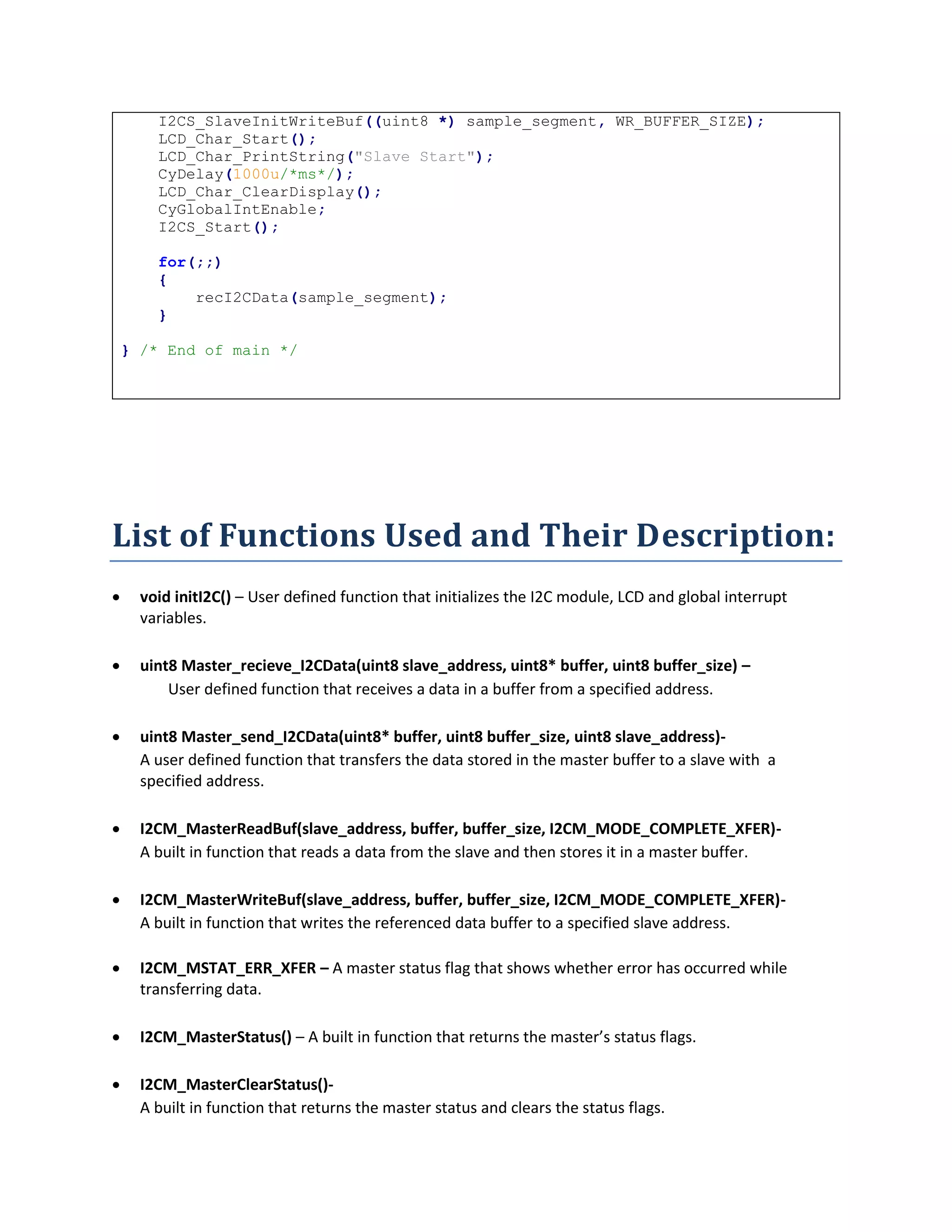
I2CS_SlaveInitWriteBuf((uint8 *) sample_segment, WR_BUFFER_SIZE);
LCD_Char_Start();
LCD_Char_PrintString("Slave Start");
CyDelay(1000u/*ms*/);
LCD_Char_ClearDisplay();
CyGlobalIntEnable;
I2CS_Start();
for(;;)
{
recI2CData(sample_segment,WR_BUFFER_SIZE);
}
} /* End of main */
/* [] END OF FILE */
Bidirectional Data Transfer:
Master receives an array from one slave device with a specified address and then sends the data
to another slave having another slave address (indirect slave-to-slave communication).
MASTER (Transmitter/Receiver):
#include <project.h>
#include <stdio.h>
#define I2C_SLAVE_ADDRESS (0x10u)
#define I2C_SLAVE_ADDRESS1 (0x08u)
#define WR_BUFFER_SIZE1 (0x05u)
#define WR_BUFFER_SIZE2 (0x05u)](https://image.slidesharecdn.com/9b3bbdc5-1ab0-49f4-a71a-e0bef009c45e-160421173910/75/Final-Report-24-2048.jpg)
![void initI2C()
{
LCD_Char_Start();
LCD_Char_PrintString("Master Start");
CyDelay(1000u);
LCD_Char_ClearDisplay();
CyGlobalIntEnable;
I2CM_Start();
}
uint8 Master_recieve_I2CData(uint8 slave_address, uint8* buffer, uint8
buffer_size)
{
uint8 i = 0u;
uint8 temp;
uint8 res;
do
{
/* The syntax below automatically writes a buffer of data to a
slave
* device from start to stop.
*/
temp = I2CM_MasterReadBuf(slave_address, buffer, buffer_size,
I2CM_MODE_COMPLETE_XFER);
}
while (temp != I2CM_MSTR_NO_ERROR);
/* Wait for the data transfer to complete */
while(I2CM_MasterStatus() & I2CM_MSTAT_XFER_INP);
temp = I2CM_MasterClearStatus();
/* If there is an error while transferring data */
if (temp & I2CM_MSTAT_ERR_XFER)
{
/* Indicate the error */
res = 0;
LCD_Char_PrintString("I2C Error! ");
CyDelay(2000u/*ms*/);
LCD_Char_ClearDisplay();
}
else /* Write completed without error */
{
/* For verification purposes, display the Reading on the LCD */
res = 1;
LCD_Char_Position(0,0);
for(i=0;i<buffer_size;i++)
{
LCD_Char_PutChar(buffer[i]);
//CyDelay(100u/*ms*/);
}
}](https://image.slidesharecdn.com/9b3bbdc5-1ab0-49f4-a71a-e0bef009c45e-160421173910/75/Final-Report-25-2048.jpg)
![/* Delay introduced for ease of reading LCD */
CyDelay(1000u/*ms*/);
LCD_Char_ClearDisplay();
CyDelay(1000u/*ms*/);
return res;
}
uint8 Master_send_I2CData(uint8* buffer, uint8 buffer_size, uint8
slave_address)
{
uint8 i = 0u;
uint8 temp;
uint8 res;
/* Attempt to initiate communication with the slave until the function
* completes without error.
*/
do
{
/* The syntax below automatically writes a buffer of data to a
slave
* device from start to stop.
*/
temp = I2CM_MasterWriteBuf(slave_address, buffer, buffer_size,
I2CM_MODE_COMPLETE_XFER);
}
while (temp != I2CM_MSTR_NO_ERROR);
/* Wait for the data transfer to complete */
while(I2CM_MasterStatus() & I2CM_MSTAT_XFER_INP);
temp = I2CM_MasterClearStatus();
/* If there is an error while transferring data */
if(temp & I2CM_MSTAT_ERR_XFER)
{
/* Indicate the error */
LCD_Char_PrintString("I2C Error! ");
CyDelay(2000u/*ms*/);
LCD_Char_ClearDisplay();
res = 0;
}
else /* Write completed without error */
{
/* For verification purposes, display the Reading on the LCD */
LCD_Char_Position(0,0);
for(i=0;i<buffer_size;i++)
{
LCD_Char_PutChar(buffer[i]);
}
res = 1;
}
CyDelay(1000u/*ms*/);
LCD_Char_ClearDisplay();](https://image.slidesharecdn.com/9b3bbdc5-1ab0-49f4-a71a-e0bef009c45e-160421173910/75/Final-Report-26-2048.jpg)
![CyDelay(1000u/*ms*/);
return res;
}
int main()
{
uint8 sample_segment1[WR_BUFFER_SIZE1] ;
initI2C();
for(;;)
{
Master_recieve_I2CData(I2C_SLAVE_ADDRESS, sample_segment1,
WR_BUFFER_SIZE1);
Master_send_I2CData(sample_segment1,
WR_BUFFER_SIZE1,I2C_SLAVE_ADDRESS1);
}
}
/* [] END OF FILE */
SLAVE (Receiver):
#include <project.h>
#define WR_BUFFER_SIZE (5u)
void recI2CData(uint8* buffer, uint8 buffer_size)
{
uint8 i = 0u;
uint8 byteCount = 0u;
/* Check if the slave buffer has been read */
if(I2CS_SlaveStatus() & I2CS_SSTAT_WR_CMPLT)
{
byteCount = I2CS_SlaveGetWriteBufSize();
I2CS_SlaveClearWriteStatus();
I2CS_SlaveClearWriteBuf();
/* If both bytes of the read buffer have been read */
if(byteCount == buffer_size)
{
/* Display data that was placed in the buffer on the
LCD and verify
* this is same as that received by master */
LCD_Char_Position(0,0);
for(i=0;i<buffer_size;i++)](https://image.slidesharecdn.com/9b3bbdc5-1ab0-49f4-a71a-e0bef009c45e-160421173910/75/Final-Report-27-2048.jpg)
![{
LCD_Char_PutChar(buffer[i]);
}
}
else /* Wrong number of bytes read */
{
LCD_Char_ClearDisplay();
LCD_Char_PrintString("I2C Slave Error!");
}
}
CyDelay(1000u/*ms*/);
LCD_Char_ClearDisplay();
}
int main()
{
uint8 i = 0u;
uint8 byteCount = 0u;
uint8 sample_segment[WR_BUFFER_SIZE];
/* Set up slave read data buffer */
I2CS_SlaveInitWriteBuf((uint8 *) sample_segment, WR_BUFFER_SIZE);
LCD_Char_Start();
LCD_Char_PrintString("Slave Start");
CyDelay(1000u/*ms*/);
LCD_Char_ClearDisplay();
CyGlobalIntEnable;
I2CS_Start();
for(;;)
{
recI2CData(sample_segment,WR_BUFFER_SIZE);
}
} /* End of main */
SLAVE (Transmitter):
#include <device.h>
#define WR_BUFFER_SIZE (0x05u)
void recI2CData(uint8* buffer, uint8 buffer_size)
{
uint8 i = 0u;
uint8 byteCount = 0u;
if(I2CS_SlaveStatus() & I2CS_SSTAT_RD_CMPLT)
{](https://image.slidesharecdn.com/9b3bbdc5-1ab0-49f4-a71a-e0bef009c45e-160421173910/75/Final-Report-28-2048.jpg)
![byteCount = I2CS_SlaveGetReadBufSize();
I2CS_SlaveClearReadStatus();
I2CS_SlaveClearReadBuf();
/* If both bytes of the read buffer have been read */
if(byteCount == buffer_size)
{
/* Display data that was placed in the buffer on the LCD and
verify
* this is same as that received by master */
LCD_Char_Position(0,0);
for(i=0;i<buffer_size;i++)
{
LCD_Char_PutChar(buffer[i]);
}
}
else /* Wrong number of bytes read */
{
LCD_Char_ClearDisplay();
LCD_Char_PrintString("I2C Slave Error!");
}
}
CyDelay(1000u/*ms*/);
LCD_Char_ClearDisplay();
CyDelay(1000u/*ms*/);
}
int main()
{
uint8 i = 0u;
uint8 byteCount = 0u;
uint8 sample_segment[WR_BUFFER_SIZE] = "12345";
/* Set up slave read data buffer */
LCD_Char_Start();
LCD_Char_PrintString("Slave Start");
CyDelay(1000u/*ms*/);
LCD_Char_ClearDisplay();
I2CS_SlaveInitReadBuf((uint8 *) sample_segment, WR_BUFFER_SIZE);
CyGlobalIntEnable;
I2CS_Start();
for(;;)
{
recI2CData(sample_segment, WR_BUFFER_SIZE);
}
} /* End of main */](https://image.slidesharecdn.com/9b3bbdc5-1ab0-49f4-a71a-e0bef009c45e-160421173910/75/Final-Report-29-2048.jpg)
![}
else /* Write completed without error */
{
/* For verification purposes, display the Reading on the LCD */
LCD_Char_Position(0,0);
for(i=2;i<buffer_size;i++)
{
LCD_Char_PutChar(buffer[i]);
}
res = 1;
}
CyDelay(1000u/*ms*/);
LCD_Char_ClearDisplay();
CyDelay(1000u/*ms*/);
return res;
}
int main()
{
uint8 sample_segment[7] = "00Mutee";
uint8 sample_segment2[5] = "00Ali";
sample_segment[0] = 1;
sample_segment[1] = 5;
sample_segment2[0] = 1;
sample_segment2[1] = 3;
LCD_Char_Start();
LCD_Char_PrintString("Master Start");
CyDelay(1000u/*ms*/);
LCD_Char_ClearDisplay();
CyGlobalIntEnable;
I2CM_Start();
for(;;)
{
sendI2CData(sample_segment, 7, 16u);
sendI2CData(sample_segment2, 5, 8u);
}
}
/* [] END OF FILE */](https://image.slidesharecdn.com/9b3bbdc5-1ab0-49f4-a71a-e0bef009c45e-160421173910/75/Final-Report-31-2048.jpg)
![RECEIVER (Slave):
#include <project.h>
#define WR_BUFFER_SIZE (10u)
void recI2CData(uint8* buffer)
{
uint8 i = 0u;
uint8 byteCount = 0u;
/* Check if the slave buffer has been read */
if(I2CS_SlaveStatus() & I2CS_SSTAT_WR_CMPLT)
{
byteCount = I2CS_SlaveGetWriteBufSize();
I2CS_SlaveClearWriteStatus();
I2CS_SlaveClearWriteBuf();
/* If both bytes of the read buffer have been read */
if(buffer[0] >= 1)
{
/* Display data that was placed in the buffer on the
LCD and verify
* this is same as that received by master */
LCD_Char_Position(0,0);
for(i=2;i<buffer[1]+2;i++)
{
LCD_Char_PutChar(buffer[i]);
}
}
else /* Wrong number of bytes read */
{
LCD_Char_ClearDisplay();
LCD_Char_PrintString("I2C Slave Error!");
}
}
CyDelay(1000u/*ms*/);
LCD_Char_ClearDisplay();
//CyDelay(1000u/*ms*/);
}
int main()
{
uint8 i = 0u;
uint8 byteCount = 0u;
uint8 sample_segment[WR_BUFFER_SIZE];
/* Set up slave read data buffer */](https://image.slidesharecdn.com/9b3bbdc5-1ab0-49f4-a71a-e0bef009c45e-160421173910/75/Final-Report-32-2048.jpg)


![uint8 _CRCbyte = 0;
uint8 dataBlock[10];
uint8 CRC;
code unsigned char crc8_table[] = {
0x00, 0x3e, 0x7c, 0x42, 0xf8, 0xc6, 0x84, 0xba, 0x95, 0xab, 0xe9,
0xd7,
0x6d, 0x53, 0x11, 0x2f, 0x4f, 0x71, 0x33, 0x0d, 0xb7, 0x89, 0xcb,
0xf5,
0xda, 0xe4, 0xa6, 0x98, 0x22, 0x1c, 0x5e, 0x60, 0x9e, 0xa0, 0xe2,
0xdc,
0x66, 0x58, 0x1a, 0x24, 0x0b, 0x35, 0x77, 0x49, 0xf3, 0xcd, 0x8f,
0xb1,
0xd1, 0xef, 0xad, 0x93, 0x29, 0x17, 0x55, 0x6b, 0x44, 0x7a, 0x38,
0x06,
0xbc, 0x82, 0xc0, 0xfe, 0x59, 0x67, 0x25, 0x1b, 0xa1, 0x9f, 0xdd,
0xe3,
0xcc, 0xf2, 0xb0, 0x8e, 0x34, 0x0a, 0x48, 0x76, 0x16, 0x28, 0x6a,
0x54,
0xee, 0xd0, 0x92, 0xac, 0x83, 0xbd, 0xff, 0xc1, 0x7b, 0x45, 0x07,
0x39,
0xc7, 0xf9, 0xbb, 0x85, 0x3f, 0x01, 0x43, 0x7d, 0x52, 0x6c, 0x2e,
0x10,
0xaa, 0x94, 0xd6, 0xe8, 0x88, 0xb6, 0xf4, 0xca, 0x70, 0x4e, 0x0c,
0x32,
0x1d, 0x23, 0x61, 0x5f, 0xe5, 0xdb, 0x99, 0xa7, 0xb2, 0x8c, 0xce,
0xf0,
0x4a, 0x74, 0x36, 0x08, 0x27, 0x19, 0x5b, 0x65, 0xdf, 0xe1, 0xa3,
0x9d,
0xfd, 0xc3, 0x81, 0xbf, 0x05, 0x3b, 0x79, 0x47, 0x68, 0x56, 0x14,
0x2a,
0x90, 0xae, 0xec, 0xd2, 0x2c, 0x12, 0x50, 0x6e, 0xd4, 0xea, 0xa8,
0x96,
0xb9, 0x87, 0xc5, 0xfb, 0x41, 0x7f, 0x3d, 0x03, 0x63, 0x5d, 0x1f,
0x21,
0x9b, 0xa5, 0xe7, 0xd9, 0xf6, 0xc8, 0x8a, 0xb4, 0x0e, 0x30, 0x72,
0x4c,](https://crownmelresort.com/image.slidesharecdn.com/9b3bbdc5-1ab0-49f4-a71a-e0bef009c45e-160421173910/75/Final-Report-9-2048.jpg)

![crc = crc & 1 ? (crc >> 1) ^ POLY : crc >> 1;
crc = crc & 1 ? (crc >> 1) ^ POLY : crc >> 1;
crc = crc & 1 ? (crc >> 1) ^ POLY : crc >> 1;
crc = crc & 1 ? (crc >> 1) ^ POLY : crc >> 1;
crc = crc & 1 ? (crc >> 1) ^ POLY : crc >> 1;
crc = crc & 1 ? (crc >> 1) ^ POLY : crc >> 1;
} while (dataBlock < end);
return crc ^ 0xff;
}
void printArray()
{
LCD_Char_1_Position(0u, 0u);
LCD_Char_1_PrintHexUint8(dataBlock[0]);
LCD_Char_1_PrintHexUint8(dataBlock[1]);
LCD_Char_1_PrintHexUint8(CRC);
LCD_Char_1_Position(1u, 0u);
for(i=2; i<dataBlock[1]+2; i++)
{
LCD_Char_1_PrintHexUint8(dataBlock[i]);
}
}
int main()
{
UART_1_Start();
LCD_Char_1_Start();
initHandshake();
for(;;)
{
}](https://crownmelresort.com/image.slidesharecdn.com/9b3bbdc5-1ab0-49f4-a71a-e0bef009c45e-160421173910/75/Final-Report-11-2048.jpg)
![}
void TX_ISR()
{
return;
}
void RX_ISR()
{
if (!isHSDone)
{
handshake_byte = UART_1_GetByte();
if (handshake_byte == HANDSHAKE_VAR)
UART_1_PutChar(HANDSHAKE_VAR);
isHSDone = 1;
_formatSpecifier = 1;
return;
}
else if (_formatSpecifier)
{
dataBlock[i] = UART_1_GetChar();
i++;
_formatSpecifier = 0;
_packetSize = 1;
}
else if (_packetSize)
{
dataBlock[i] = UART_1_GetChar();
i++;
_packetSize = 0;
_blockData = 1;
}](https://crownmelresort.com/image.slidesharecdn.com/9b3bbdc5-1ab0-49f4-a71a-e0bef009c45e-160421173910/75/Final-Report-12-2048.jpg)
![else if (_blockData)
{
dataBlock[i] = UART_1_GetChar();
i++;
if (i == dataBlock[1]+2)
{
_blockData = 0;
_CRCbyte = 1;
}
}
else if (_CRCbyte)
{
CRC = UART_1_GetChar();
if (CRC == crc8_slow(0, dataBlock, dataBlock[1]+2))
{
CYGlobalIntDisable;
printArray();
}
else
{
CYGlobalIntDisable;
LCD_Char_1_Position(1u, 8u);
LCD_Char_1_PrintString("CRC err");
printArray();
}
_CRCbyte = 0;
}
}](https://crownmelresort.com/image.slidesharecdn.com/9b3bbdc5-1ab0-49f4-a71a-e0bef009c45e-160421173910/75/Final-Report-13-2048.jpg)
![TRANSMITTER:
#define HANDSHAKE_VAR 255
#define POLY 0xB2
#define packetSize 5
uint8 isHSDone = 0;
uint8 handshake_byte = 0;
uint8 TxByte=0;
code unsigned char crc8_table[] = {
0x00, 0x3e, 0x7c, 0x42, 0xf8, 0xc6, 0x84, 0xba, 0x95, 0xab, 0xe9,
0xd7,
0x6d, 0x53, 0x11, 0x2f, 0x4f, 0x71, 0x33, 0x0d, 0xb7, 0x89, 0xcb,
0xf5,
0xda, 0xe4, 0xa6, 0x98, 0x22, 0x1c, 0x5e, 0x60, 0x9e, 0xa0, 0xe2,
0xdc,
0x66, 0x58, 0x1a, 0x24, 0x0b, 0x35, 0x77, 0x49, 0xf3, 0xcd, 0x8f,
0xb1,
0xd1, 0xef, 0xad, 0x93, 0x29, 0x17, 0x55, 0x6b, 0x44, 0x7a, 0x38,
0x06,
0xbc, 0x82, 0xc0, 0xfe, 0x59, 0x67, 0x25, 0x1b, 0xa1, 0x9f, 0xdd,
0xe3,
0xcc, 0xf2, 0xb0, 0x8e, 0x34, 0x0a, 0x48, 0x76, 0x16, 0x28, 0x6a,
0x54,
0xee, 0xd0, 0x92, 0xac, 0x83, 0xbd, 0xff, 0xc1, 0x7b, 0x45, 0x07,
0x39,
0xc7, 0xf9, 0xbb, 0x85, 0x3f, 0x01, 0x43, 0x7d, 0x52, 0x6c, 0x2e,
0x10,
0xaa, 0x94, 0xd6, 0xe8, 0x88, 0xb6, 0xf4, 0xca, 0x70, 0x4e, 0x0c,
0x32,
0x1d, 0x23, 0x61, 0x5f, 0xe5, 0xdb, 0x99, 0xa7, 0xb2, 0x8c, 0xce,
0xf0,
0x4a, 0x74, 0x36, 0x08, 0x27, 0x19, 0x5b, 0x65, 0xdf, 0xe1, 0xa3,
0x9d,
0xfd, 0xc3, 0x81, 0xbf, 0x05, 0x3b, 0x79, 0x47, 0x68, 0x56, 0x14,
0x2a,](https://crownmelresort.com/image.slidesharecdn.com/9b3bbdc5-1ab0-49f4-a71a-e0bef009c45e-160421173910/75/Final-Report-14-2048.jpg)
![0x90, 0xae, 0xec, 0xd2, 0x2c, 0x12, 0x50, 0x6e, 0xd4, 0xea, 0xa8,
0x96,
0xb9, 0x87, 0xc5, 0xfb, 0x41, 0x7f, 0x3d, 0x03, 0x63, 0x5d, 0x1f,
0x21,
0x9b, 0xa5, 0xe7, 0xd9, 0xf6, 0xc8, 0x8a, 0xb4, 0x0e, 0x30, 0x72,
0x4c,
0xeb, 0xd5, 0x97, 0xa9, 0x13, 0x2d, 0x6f, 0x51, 0x7e, 0x40, 0x02,
0x3c,
0x86, 0xb8, 0xfa, 0xc4, 0xa4, 0x9a, 0xd8, 0xe6, 0x5c, 0x62, 0x20,
0x1e,
0x31, 0x0f, 0x4d, 0x73, 0xc9, 0xf7, 0xb5, 0x8b, 0x75, 0x4b, 0x09,
0x37,
0x8d, 0xb3, 0xf1, 0xcf, 0xe0, 0xde, 0x9c, 0xa2, 0x18, 0x26, 0x64,
0x5a,
0x3a, 0x04, 0x46, 0x78, 0xc2, 0xfc, 0xbe, 0x80, 0xaf, 0x91, 0xd3,
0xed,
0x57, 0x69, 0x2b, 0x15 };
uint8 array[7] = {1, 5, 10, 11, 12, 13, 14};
void initHandshake()
{
UART_1_PutChar(HANDSHAKE_VAR);
RX_ISR_Start();
RX_ISR_SetVector(RX_ISR_Interrupt);
while (handshake_byte != HANDSHAKE_VAR);
isHSDone = 1;
LCD_Char_1_Position(0u, 5u);
LCD_Char_1_PrintString("Sync Done");
}
unsigned crc8_slow(unsigned crc, unsigned char *dataBlock, uint8 len)
{
unsigned char *end;](https://crownmelresort.com/image.slidesharecdn.com/9b3bbdc5-1ab0-49f4-a71a-e0bef009c45e-160421173910/75/Final-Report-15-2048.jpg)

![CRC = crc8_slow(0, array, packetSize+2);
for(i=0; i<7; i++)
{
UART_1_PutChar(array[i]);
}
UART_1_PutChar(CRC);
while(1)
{
LCD_Char_1_Position(0u, 0u);
LCD_Char_1_PrintString("HS/Array Out");
LCD_Char_1_Position(1u, 0u);
LCD_Char_1_PrintHexUint8(CRC);
}
}
void TX_ISR()
{
return;
}
void RX_ISR()
{
if (!isHSDone)
{
handshake_byte = UART_1_GetByte();
}
else
{
}
}](https://crownmelresort.com/image.slidesharecdn.com/9b3bbdc5-1ab0-49f4-a71a-e0bef009c45e-160421173910/75/Final-Report-17-2048.jpg)

![Modes of operation:
There are four possible modes of operation for a given bus device:
master transmit — master is sending data to a slave
master receive — master is receiving data from a slave
slave transmit — slave is sending data to the master
slave receive — slave is receiving data from the master
I2C and PSOC development kit:
Supports Slave, Master, Multi-Master and Multi-Master-Slave operation
Only two pins (SDA and SCL) required to interface to I2C bus
Standard data rates of 100/400/1000 kbps supported
High level APIs require minimal user programming
Data Rate
This parameter is used to set the I2C data rate value up to 1000 kbps; the actual speed may differ based
on available clock speed and divider range. The standard speeds are 50, 100 (default), 400, and 1000
kbps.
Pin Connections:
SCL P12[0]
SDA P12[1]
Master Operation:
When the master wants to transmit something it starts it by sending a start bit followed by the 7-bit
address of the slave it wishes to communicate with, which is finally followed by a single bit representing
whether it wishes to write(0) to or read(1) from the slave.](https://crownmelresort.com/image.slidesharecdn.com/9b3bbdc5-1ab0-49f4-a71a-e0bef009c45e-160421173910/75/Final-Report-19-2048.jpg)


![else /* Write completed without error */
{
res = 1;
}
LCD_Char_ClearDisplay();
return res;
}
int main()
{
uint8 x, i, j, k, a;
uint8 array[4][4] = { 1, 2, 3, 4,
5, 6, 7, 8,
9, 10, 11, 12,
13, 14, 15, 16 };
uint8 segment[4];
initI2C();
for(;;)
{
int z = 0;
for (x = 0; x < 3; x += 2)
{
for (i = 0; i < 3; i += 2)
{
for (j = 0; j < 2; j++)
{
for (k = 0; k < 2; k++)
{
segment[z] = array[x + j][i + k];
z++;
}
}
Master_send_I2CData(segment, 4, 8);
a=0;
for(j=0;j<2;j++)
{
for (k=0; k<2; k++)
{
LCD_Char_Position(j, k*3);
LCD_Char_PrintHexUint8(segment[a]);
a++;
}
}
z = 0;
CyDelay(2000);
}
}
}](https://crownmelresort.com/image.slidesharecdn.com/9b3bbdc5-1ab0-49f4-a71a-e0bef009c45e-160421173910/75/Final-Report-22-2048.jpg)
![}
/* [] END OF FILE */
RECEIVER (Slave):
#include <project.h>
#define WR_BUFFER_SIZE (4u)
void recI2CData(uint8* buffer, uint8 buffer_size)
{
uint8 i = 0u;
uint8 j, k;
uint8 byteCount = 0u;
/* Check if the slave buffer has been read */
if(I2CS_SlaveStatus() & I2CS_SSTAT_WR_CMPLT)
{
byteCount = I2CS_SlaveGetWriteBufSize();
I2CS_SlaveClearWriteStatus();
I2CS_SlaveClearWriteBuf();
/* If both bytes of the read buffer have been read */
if(byteCount == buffer_size)
{
/* Display data that was placed in the buffer on the
LCD and verify
* this is same as that received by master */
LCD_Char_Position(0,0);
for(j=0;j<2;j++)
{
for (k=0; k<2; k++)
{
LCD_Char_Position(j, k*3);
LCD_Char_PrintHexUint8(buffer[i]);
i++;
}
}
}
else /* Wrong number of bytes read */
{
LCD_Char_ClearDisplay();
LCD_Char_PrintString("I2C Slave Error!");
}](https://crownmelresort.com/image.slidesharecdn.com/9b3bbdc5-1ab0-49f4-a71a-e0bef009c45e-160421173910/75/Final-Report-23-2048.jpg)
![}
}
int main()
{
uint8 i = 0u;
uint8 byteCount = 0u;
uint8 sample_segment[WR_BUFFER_SIZE];
/* Set up slave read data buffer */
I2CS_SlaveInitWriteBuf((uint8 *) sample_segment, WR_BUFFER_SIZE);
LCD_Char_Start();
LCD_Char_PrintString("Slave Start");
CyDelay(1000u/*ms*/);
LCD_Char_ClearDisplay();
CyGlobalIntEnable;
I2CS_Start();
for(;;)
{
recI2CData(sample_segment,WR_BUFFER_SIZE);
}
} /* End of main */
/* [] END OF FILE */
Bidirectional Data Transfer:
Master receives an array from one slave device with a specified address and then sends the data
to another slave having another slave address (indirect slave-to-slave communication).
MASTER (Transmitter/Receiver):
#include <project.h>
#include <stdio.h>
#define I2C_SLAVE_ADDRESS (0x10u)
#define I2C_SLAVE_ADDRESS1 (0x08u)
#define WR_BUFFER_SIZE1 (0x05u)
#define WR_BUFFER_SIZE2 (0x05u)](https://crownmelresort.com/image.slidesharecdn.com/9b3bbdc5-1ab0-49f4-a71a-e0bef009c45e-160421173910/75/Final-Report-24-2048.jpg)
![void initI2C()
{
LCD_Char_Start();
LCD_Char_PrintString("Master Start");
CyDelay(1000u);
LCD_Char_ClearDisplay();
CyGlobalIntEnable;
I2CM_Start();
}
uint8 Master_recieve_I2CData(uint8 slave_address, uint8* buffer, uint8
buffer_size)
{
uint8 i = 0u;
uint8 temp;
uint8 res;
do
{
/* The syntax below automatically writes a buffer of data to a
slave
* device from start to stop.
*/
temp = I2CM_MasterReadBuf(slave_address, buffer, buffer_size,
I2CM_MODE_COMPLETE_XFER);
}
while (temp != I2CM_MSTR_NO_ERROR);
/* Wait for the data transfer to complete */
while(I2CM_MasterStatus() & I2CM_MSTAT_XFER_INP);
temp = I2CM_MasterClearStatus();
/* If there is an error while transferring data */
if (temp & I2CM_MSTAT_ERR_XFER)
{
/* Indicate the error */
res = 0;
LCD_Char_PrintString("I2C Error! ");
CyDelay(2000u/*ms*/);
LCD_Char_ClearDisplay();
}
else /* Write completed without error */
{
/* For verification purposes, display the Reading on the LCD */
res = 1;
LCD_Char_Position(0,0);
for(i=0;i<buffer_size;i++)
{
LCD_Char_PutChar(buffer[i]);
//CyDelay(100u/*ms*/);
}
}](https://crownmelresort.com/image.slidesharecdn.com/9b3bbdc5-1ab0-49f4-a71a-e0bef009c45e-160421173910/75/Final-Report-25-2048.jpg)
![/* Delay introduced for ease of reading LCD */
CyDelay(1000u/*ms*/);
LCD_Char_ClearDisplay();
CyDelay(1000u/*ms*/);
return res;
}
uint8 Master_send_I2CData(uint8* buffer, uint8 buffer_size, uint8
slave_address)
{
uint8 i = 0u;
uint8 temp;
uint8 res;
/* Attempt to initiate communication with the slave until the function
* completes without error.
*/
do
{
/* The syntax below automatically writes a buffer of data to a
slave
* device from start to stop.
*/
temp = I2CM_MasterWriteBuf(slave_address, buffer, buffer_size,
I2CM_MODE_COMPLETE_XFER);
}
while (temp != I2CM_MSTR_NO_ERROR);
/* Wait for the data transfer to complete */
while(I2CM_MasterStatus() & I2CM_MSTAT_XFER_INP);
temp = I2CM_MasterClearStatus();
/* If there is an error while transferring data */
if(temp & I2CM_MSTAT_ERR_XFER)
{
/* Indicate the error */
LCD_Char_PrintString("I2C Error! ");
CyDelay(2000u/*ms*/);
LCD_Char_ClearDisplay();
res = 0;
}
else /* Write completed without error */
{
/* For verification purposes, display the Reading on the LCD */
LCD_Char_Position(0,0);
for(i=0;i<buffer_size;i++)
{
LCD_Char_PutChar(buffer[i]);
}
res = 1;
}
CyDelay(1000u/*ms*/);
LCD_Char_ClearDisplay();](https://crownmelresort.com/image.slidesharecdn.com/9b3bbdc5-1ab0-49f4-a71a-e0bef009c45e-160421173910/75/Final-Report-26-2048.jpg)
![CyDelay(1000u/*ms*/);
return res;
}
int main()
{
uint8 sample_segment1[WR_BUFFER_SIZE1] ;
initI2C();
for(;;)
{
Master_recieve_I2CData(I2C_SLAVE_ADDRESS, sample_segment1,
WR_BUFFER_SIZE1);
Master_send_I2CData(sample_segment1,
WR_BUFFER_SIZE1,I2C_SLAVE_ADDRESS1);
}
}
/* [] END OF FILE */
SLAVE (Receiver):
#include <project.h>
#define WR_BUFFER_SIZE (5u)
void recI2CData(uint8* buffer, uint8 buffer_size)
{
uint8 i = 0u;
uint8 byteCount = 0u;
/* Check if the slave buffer has been read */
if(I2CS_SlaveStatus() & I2CS_SSTAT_WR_CMPLT)
{
byteCount = I2CS_SlaveGetWriteBufSize();
I2CS_SlaveClearWriteStatus();
I2CS_SlaveClearWriteBuf();
/* If both bytes of the read buffer have been read */
if(byteCount == buffer_size)
{
/* Display data that was placed in the buffer on the
LCD and verify
* this is same as that received by master */
LCD_Char_Position(0,0);
for(i=0;i<buffer_size;i++)](https://crownmelresort.com/image.slidesharecdn.com/9b3bbdc5-1ab0-49f4-a71a-e0bef009c45e-160421173910/75/Final-Report-27-2048.jpg)
![{
LCD_Char_PutChar(buffer[i]);
}
}
else /* Wrong number of bytes read */
{
LCD_Char_ClearDisplay();
LCD_Char_PrintString("I2C Slave Error!");
}
}
CyDelay(1000u/*ms*/);
LCD_Char_ClearDisplay();
}
int main()
{
uint8 i = 0u;
uint8 byteCount = 0u;
uint8 sample_segment[WR_BUFFER_SIZE];
/* Set up slave read data buffer */
I2CS_SlaveInitWriteBuf((uint8 *) sample_segment, WR_BUFFER_SIZE);
LCD_Char_Start();
LCD_Char_PrintString("Slave Start");
CyDelay(1000u/*ms*/);
LCD_Char_ClearDisplay();
CyGlobalIntEnable;
I2CS_Start();
for(;;)
{
recI2CData(sample_segment,WR_BUFFER_SIZE);
}
} /* End of main */
SLAVE (Transmitter):
#include <device.h>
#define WR_BUFFER_SIZE (0x05u)
void recI2CData(uint8* buffer, uint8 buffer_size)
{
uint8 i = 0u;
uint8 byteCount = 0u;
if(I2CS_SlaveStatus() & I2CS_SSTAT_RD_CMPLT)
{](https://crownmelresort.com/image.slidesharecdn.com/9b3bbdc5-1ab0-49f4-a71a-e0bef009c45e-160421173910/75/Final-Report-28-2048.jpg)
![byteCount = I2CS_SlaveGetReadBufSize();
I2CS_SlaveClearReadStatus();
I2CS_SlaveClearReadBuf();
/* If both bytes of the read buffer have been read */
if(byteCount == buffer_size)
{
/* Display data that was placed in the buffer on the LCD and
verify
* this is same as that received by master */
LCD_Char_Position(0,0);
for(i=0;i<buffer_size;i++)
{
LCD_Char_PutChar(buffer[i]);
}
}
else /* Wrong number of bytes read */
{
LCD_Char_ClearDisplay();
LCD_Char_PrintString("I2C Slave Error!");
}
}
CyDelay(1000u/*ms*/);
LCD_Char_ClearDisplay();
CyDelay(1000u/*ms*/);
}
int main()
{
uint8 i = 0u;
uint8 byteCount = 0u;
uint8 sample_segment[WR_BUFFER_SIZE] = "12345";
/* Set up slave read data buffer */
LCD_Char_Start();
LCD_Char_PrintString("Slave Start");
CyDelay(1000u/*ms*/);
LCD_Char_ClearDisplay();
I2CS_SlaveInitReadBuf((uint8 *) sample_segment, WR_BUFFER_SIZE);
CyGlobalIntEnable;
I2CS_Start();
for(;;)
{
recI2CData(sample_segment, WR_BUFFER_SIZE);
}
} /* End of main */](https://crownmelresort.com/image.slidesharecdn.com/9b3bbdc5-1ab0-49f4-a71a-e0bef009c45e-160421173910/75/Final-Report-29-2048.jpg)

![}
else /* Write completed without error */
{
/* For verification purposes, display the Reading on the LCD */
LCD_Char_Position(0,0);
for(i=2;i<buffer_size;i++)
{
LCD_Char_PutChar(buffer[i]);
}
res = 1;
}
CyDelay(1000u/*ms*/);
LCD_Char_ClearDisplay();
CyDelay(1000u/*ms*/);
return res;
}
int main()
{
uint8 sample_segment[7] = "00Mutee";
uint8 sample_segment2[5] = "00Ali";
sample_segment[0] = 1;
sample_segment[1] = 5;
sample_segment2[0] = 1;
sample_segment2[1] = 3;
LCD_Char_Start();
LCD_Char_PrintString("Master Start");
CyDelay(1000u/*ms*/);
LCD_Char_ClearDisplay();
CyGlobalIntEnable;
I2CM_Start();
for(;;)
{
sendI2CData(sample_segment, 7, 16u);
sendI2CData(sample_segment2, 5, 8u);
}
}
/* [] END OF FILE */](https://crownmelresort.com/image.slidesharecdn.com/9b3bbdc5-1ab0-49f4-a71a-e0bef009c45e-160421173910/75/Final-Report-31-2048.jpg)
![RECEIVER (Slave):
#include <project.h>
#define WR_BUFFER_SIZE (10u)
void recI2CData(uint8* buffer)
{
uint8 i = 0u;
uint8 byteCount = 0u;
/* Check if the slave buffer has been read */
if(I2CS_SlaveStatus() & I2CS_SSTAT_WR_CMPLT)
{
byteCount = I2CS_SlaveGetWriteBufSize();
I2CS_SlaveClearWriteStatus();
I2CS_SlaveClearWriteBuf();
/* If both bytes of the read buffer have been read */
if(buffer[0] >= 1)
{
/* Display data that was placed in the buffer on the
LCD and verify
* this is same as that received by master */
LCD_Char_Position(0,0);
for(i=2;i<buffer[1]+2;i++)
{
LCD_Char_PutChar(buffer[i]);
}
}
else /* Wrong number of bytes read */
{
LCD_Char_ClearDisplay();
LCD_Char_PrintString("I2C Slave Error!");
}
}
CyDelay(1000u/*ms*/);
LCD_Char_ClearDisplay();
//CyDelay(1000u/*ms*/);
}
int main()
{
uint8 i = 0u;
uint8 byteCount = 0u;
uint8 sample_segment[WR_BUFFER_SIZE];
/* Set up slave read data buffer */](https://crownmelresort.com/image.slidesharecdn.com/9b3bbdc5-1ab0-49f4-a71a-e0bef009c45e-160421173910/75/Final-Report-32-2048.jpg)