Downloaded 253 times
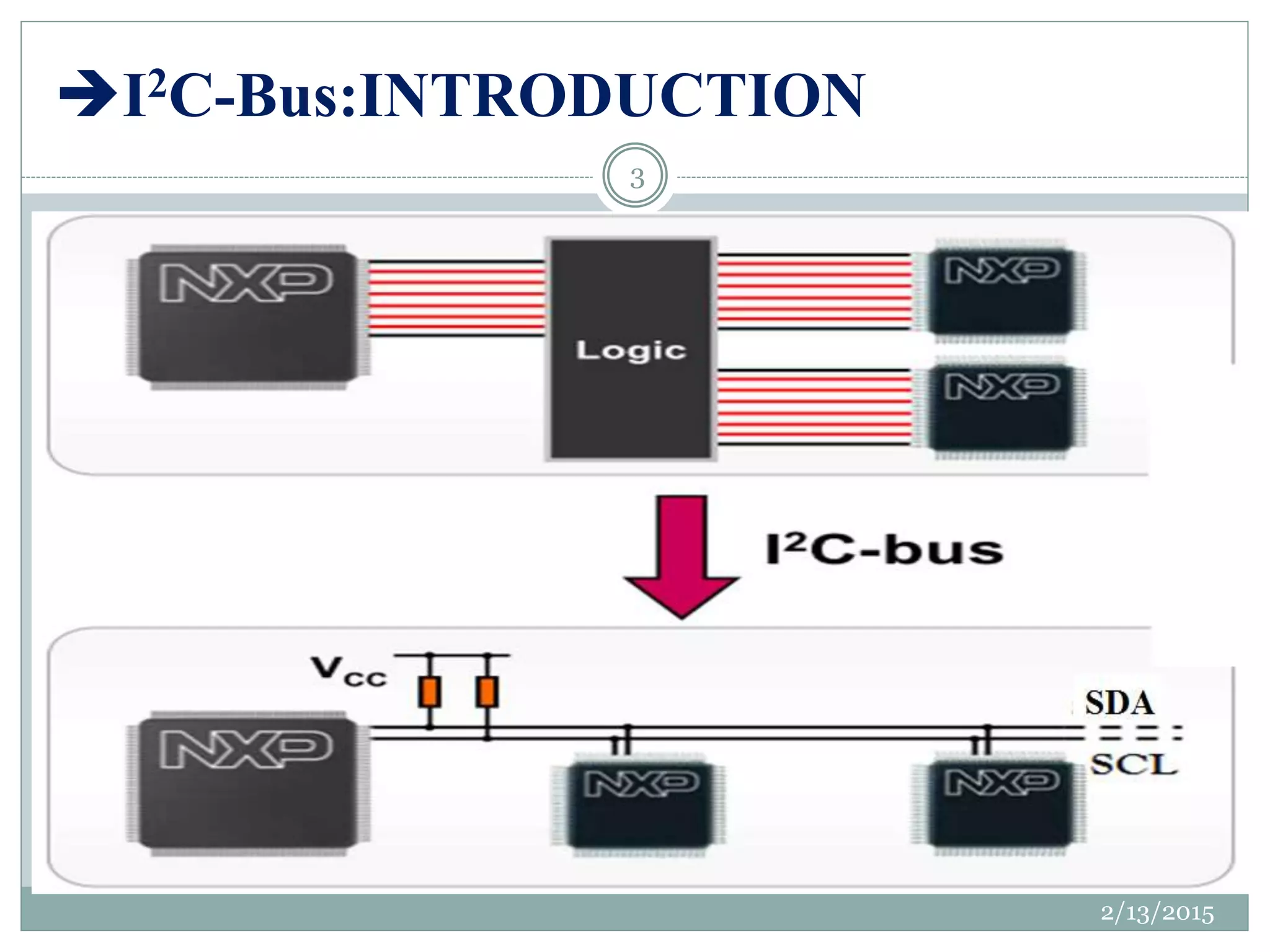

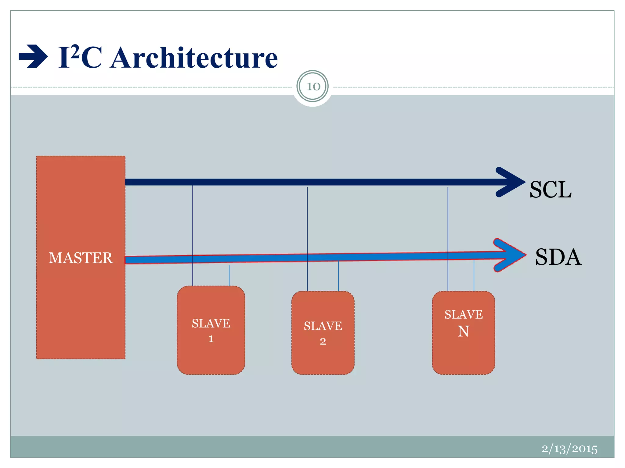

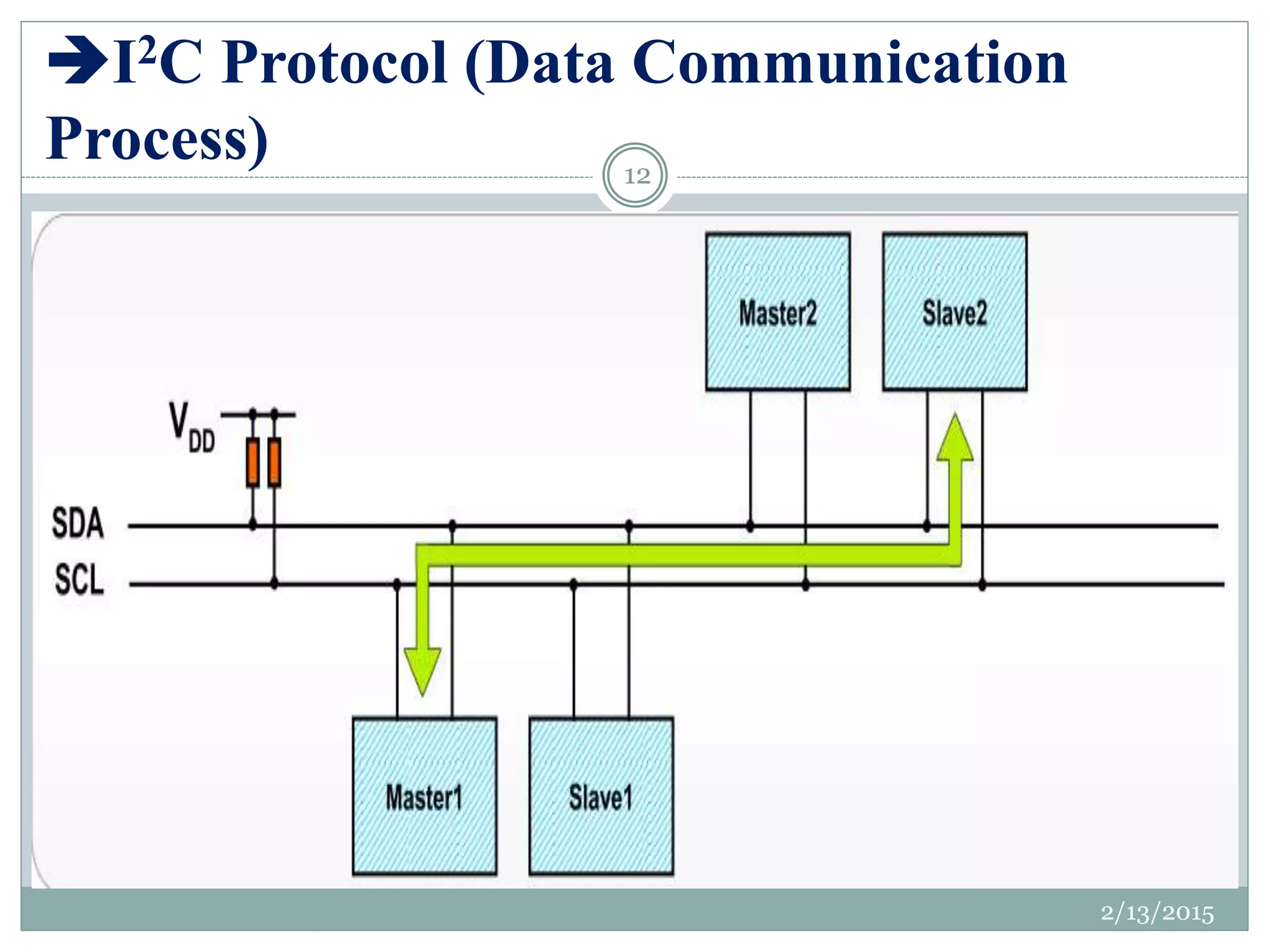
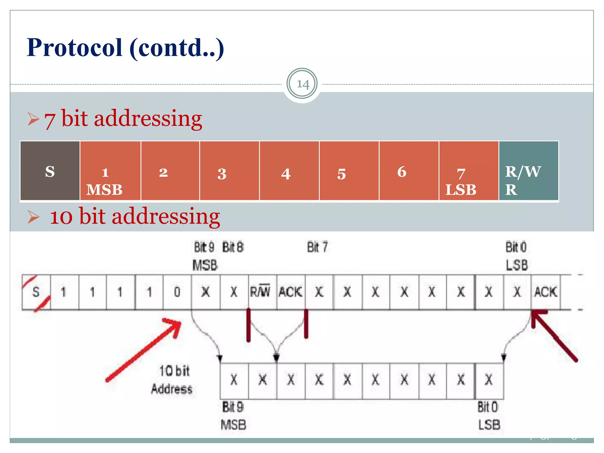
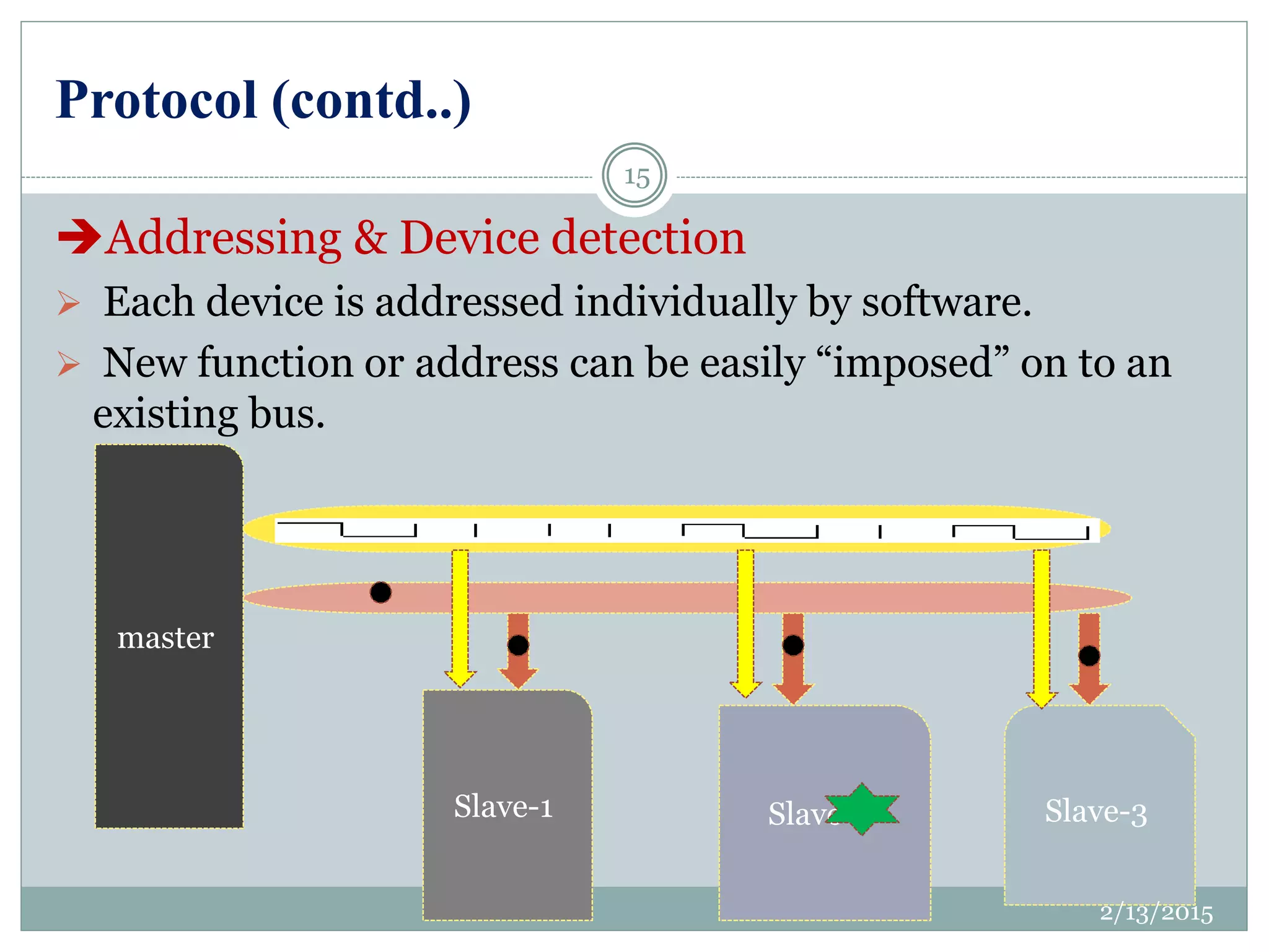
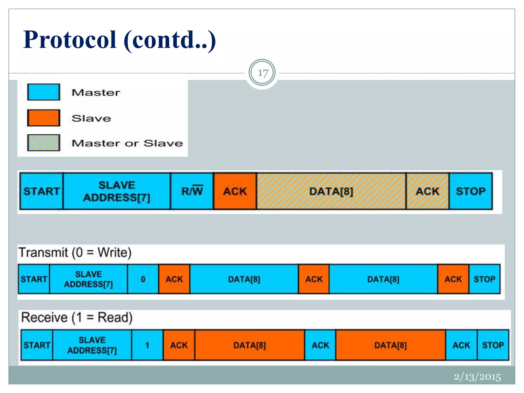
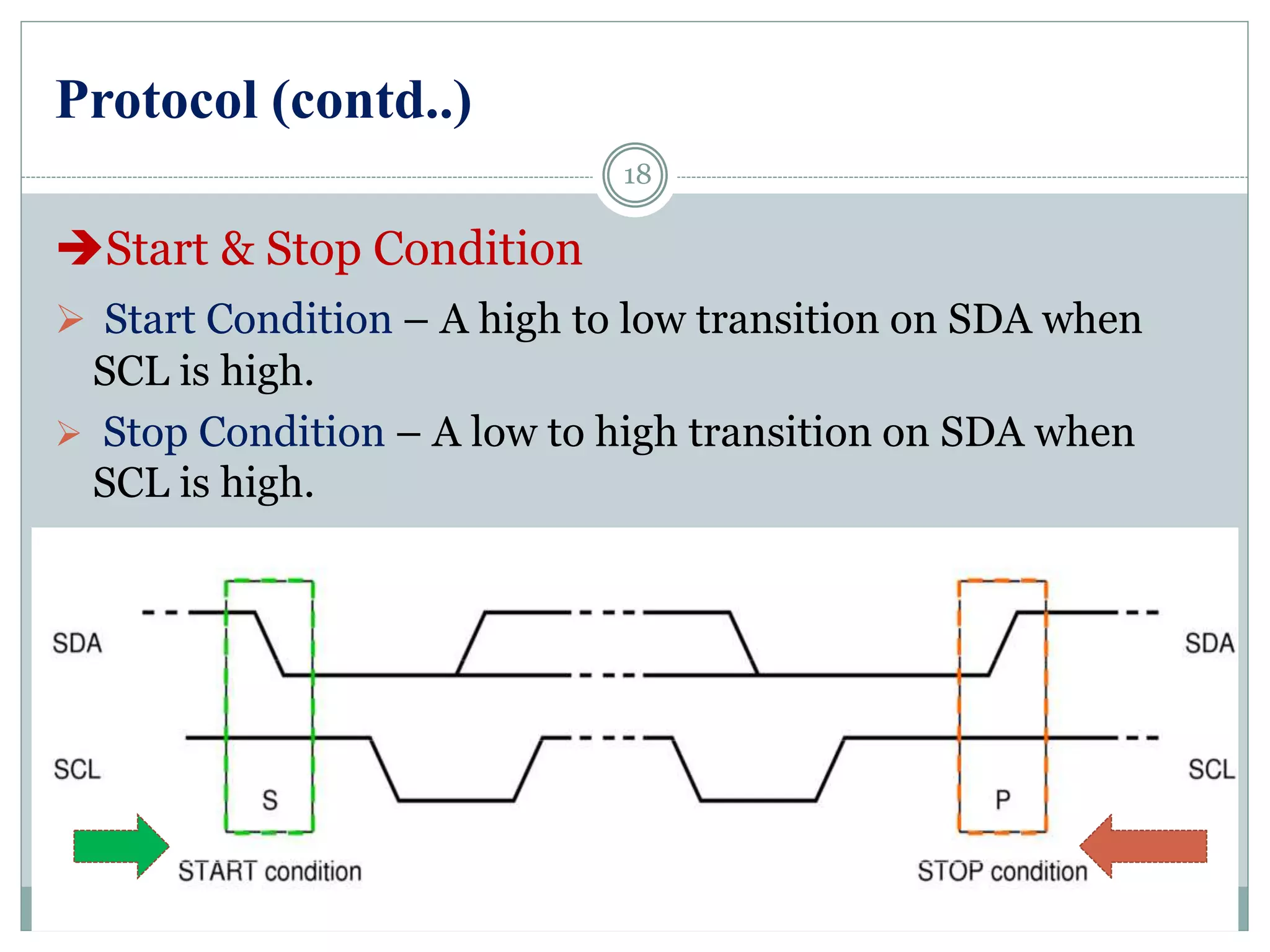
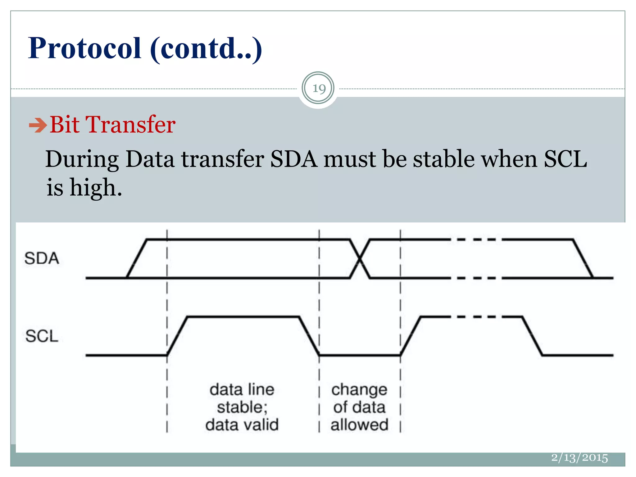
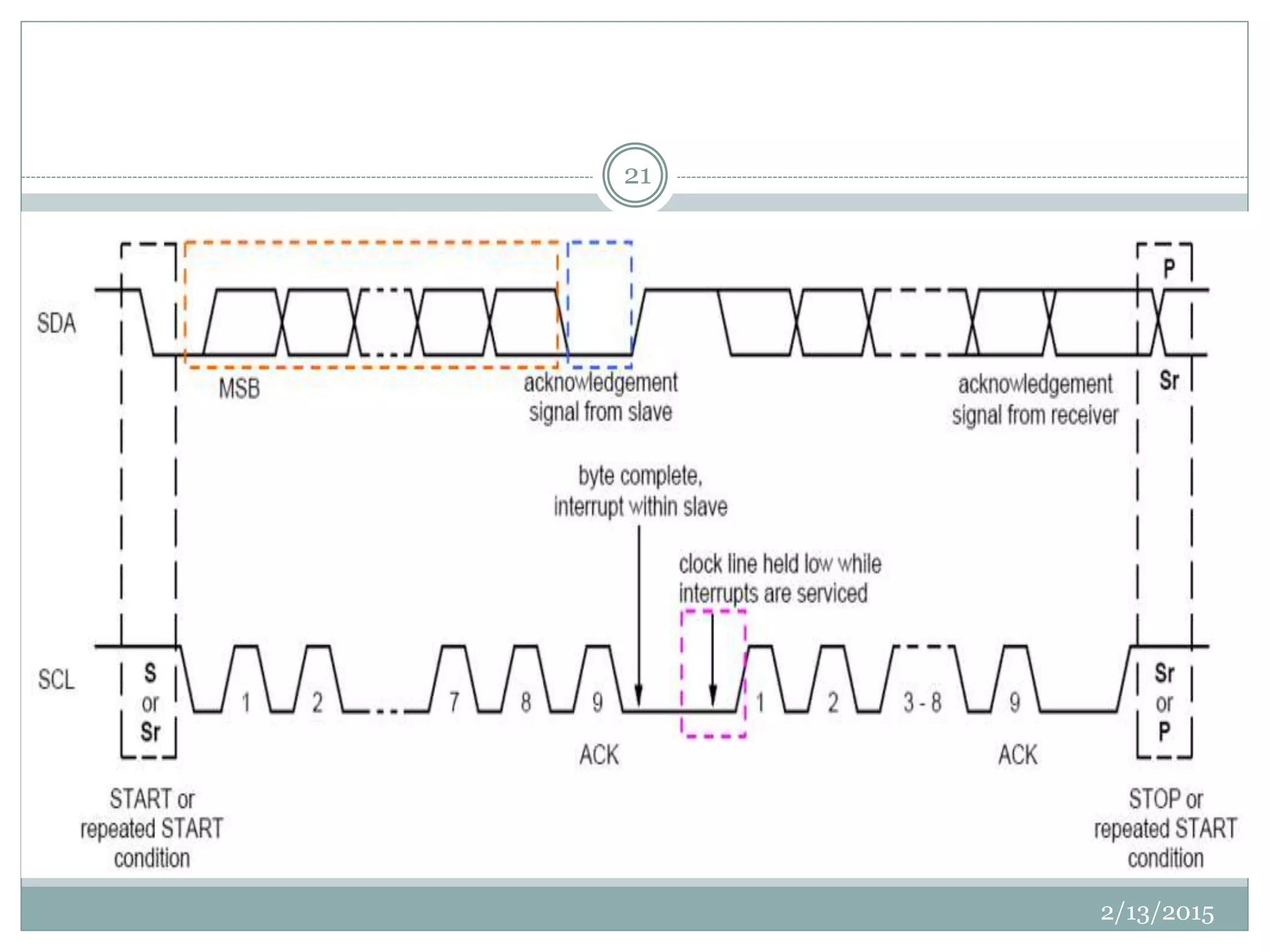
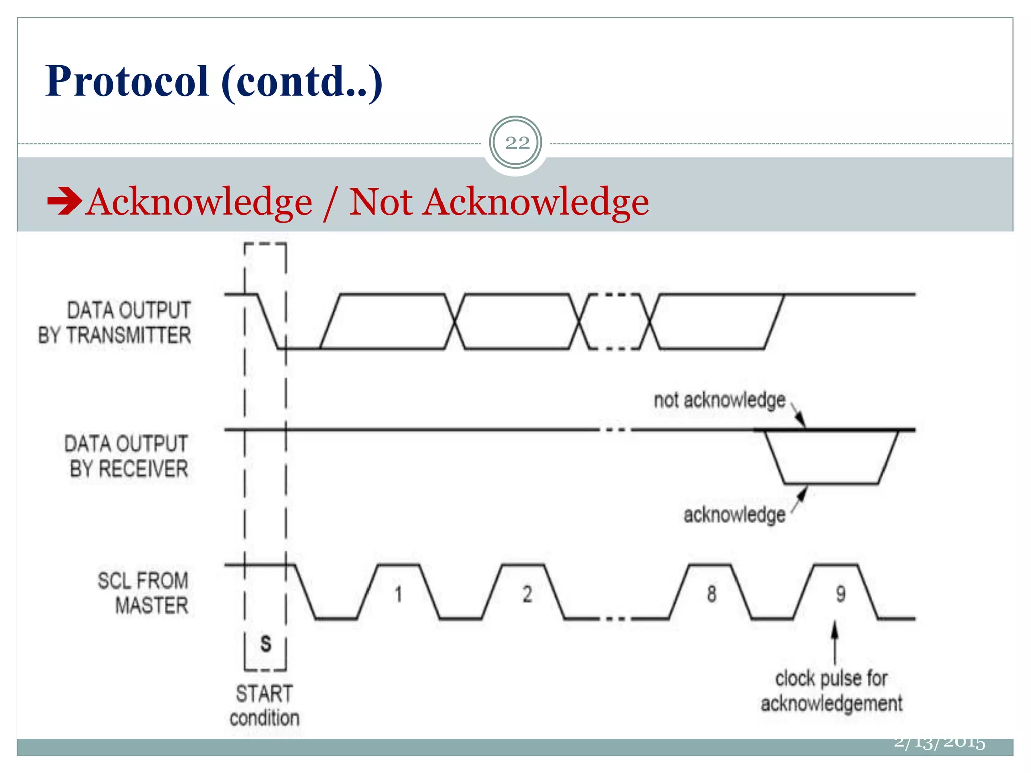
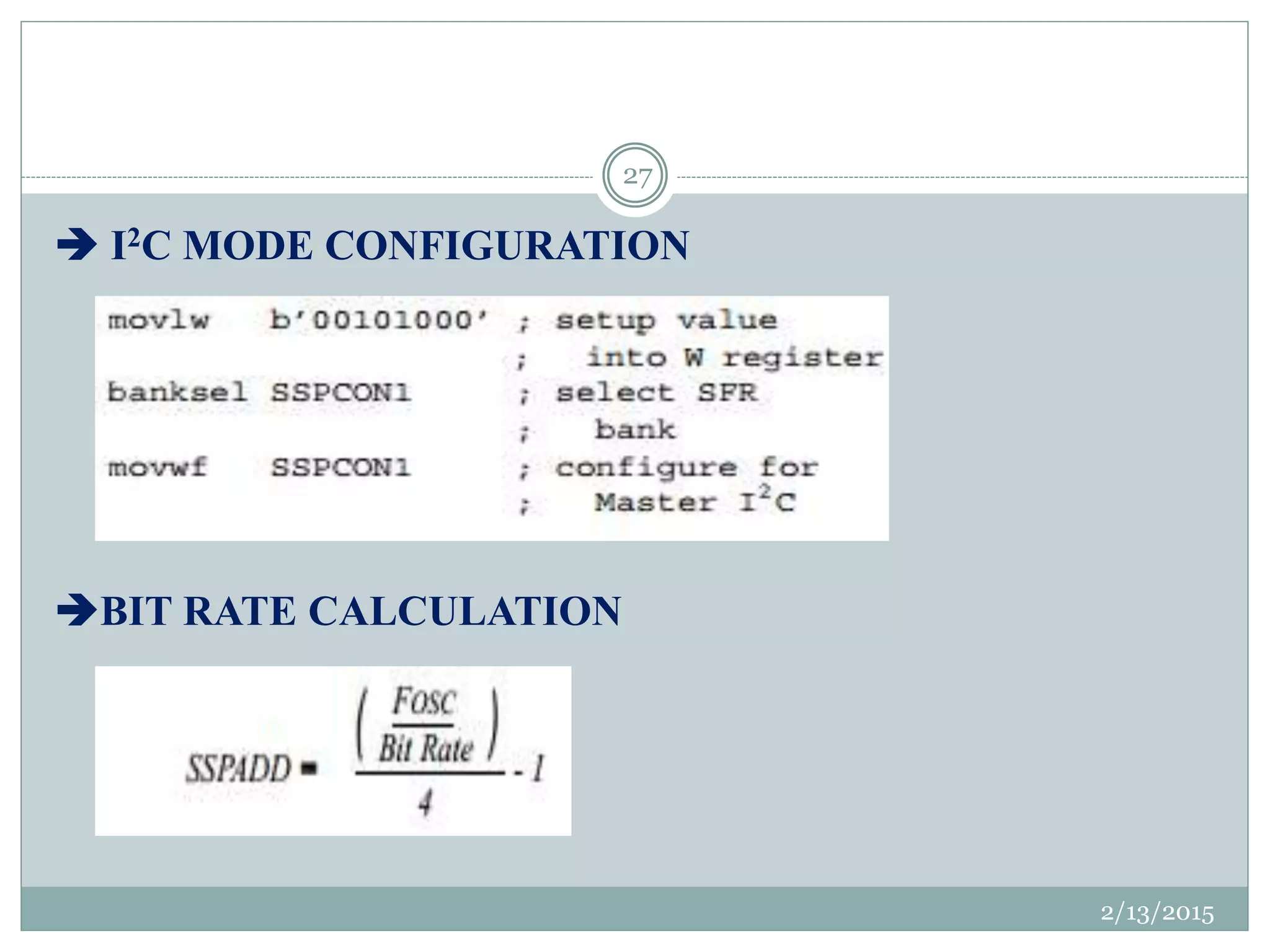
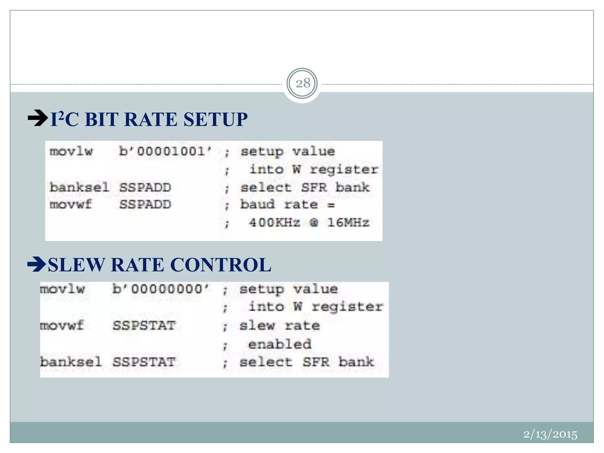
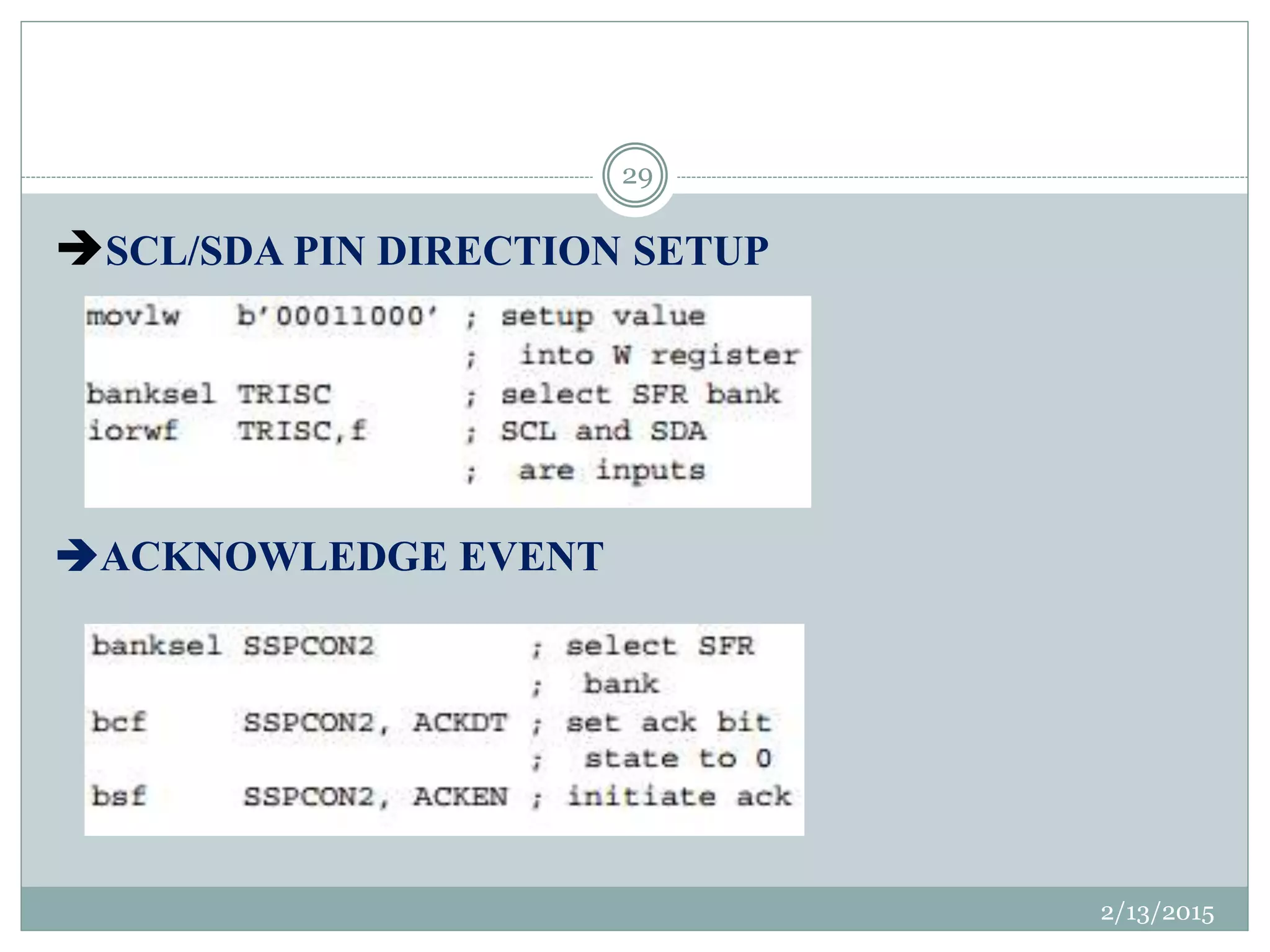
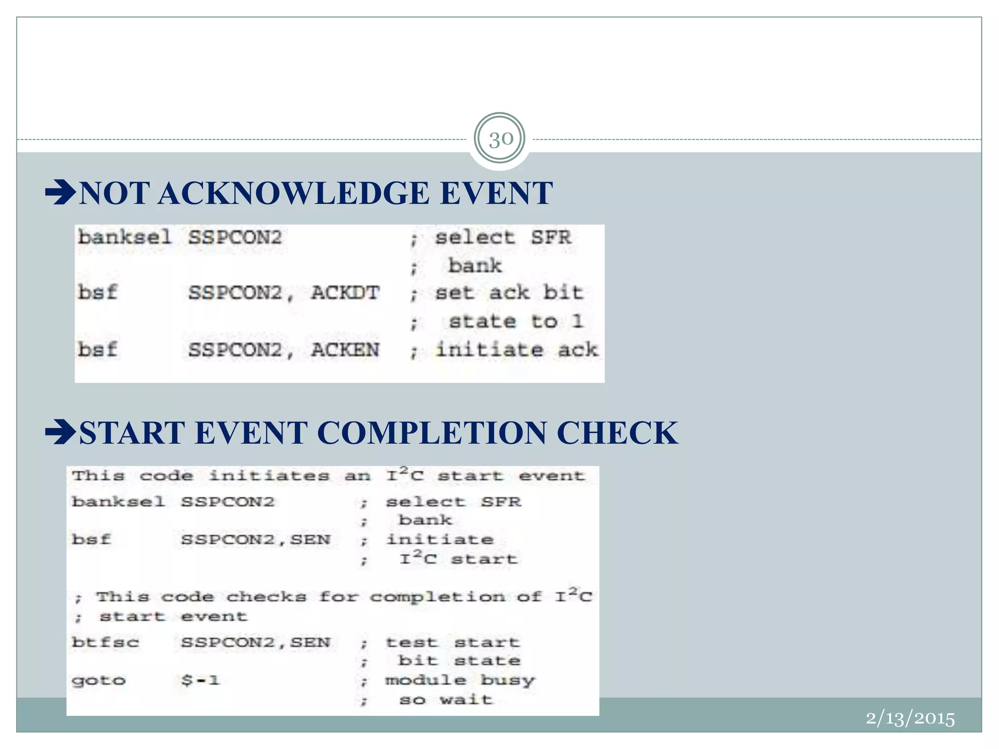
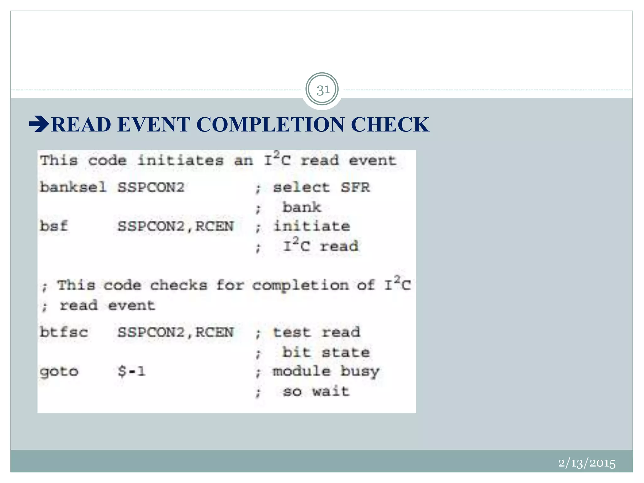
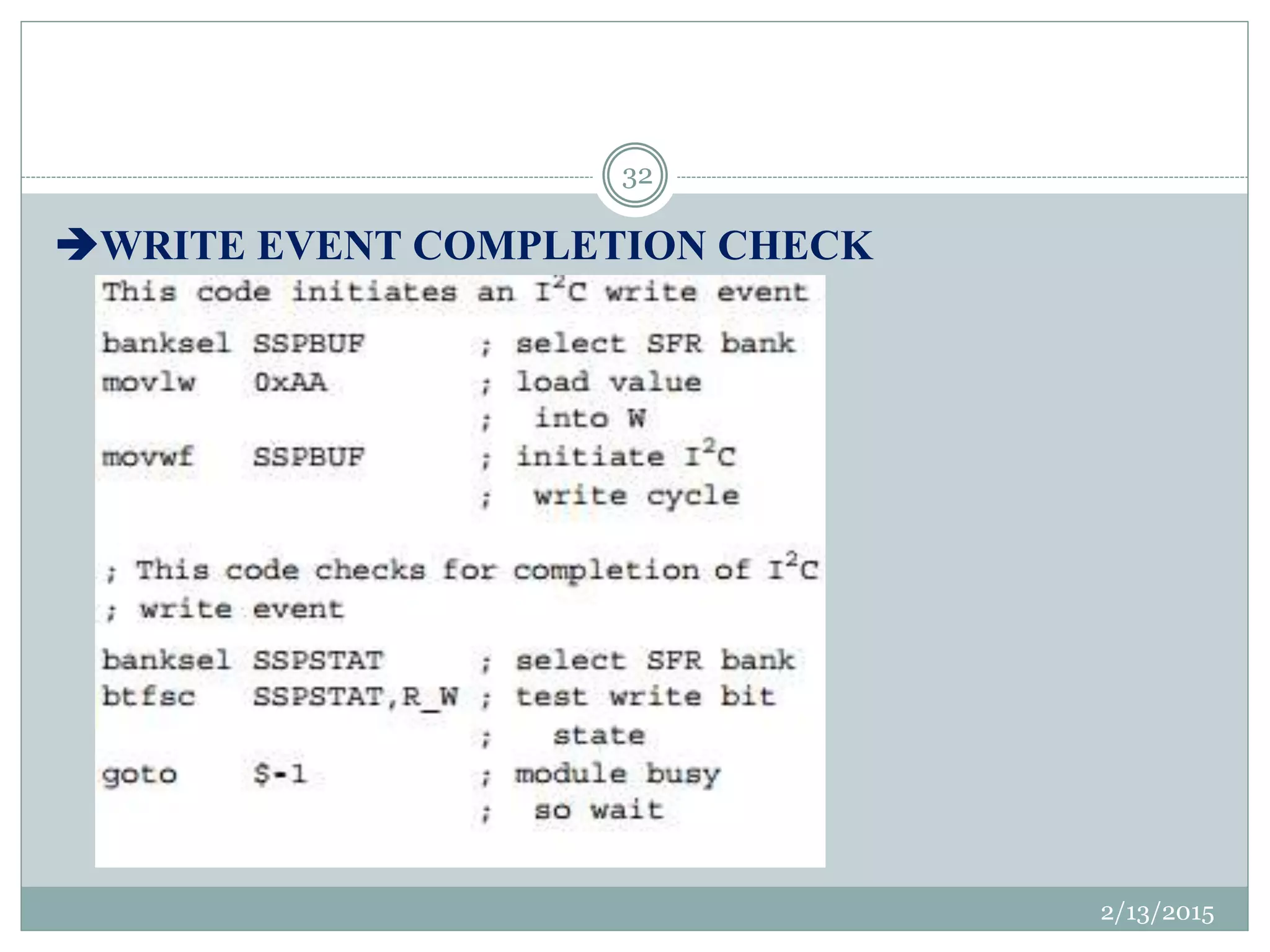
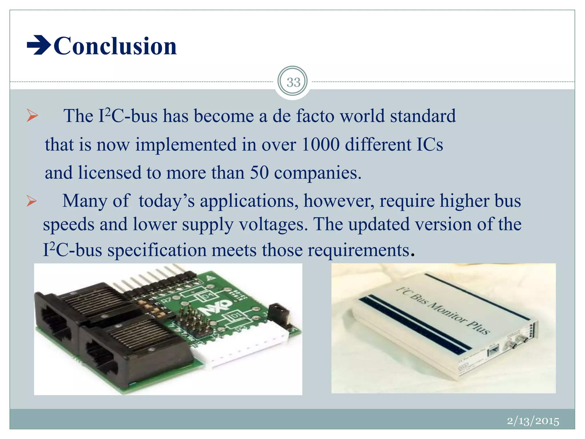


This document provides an overview of the Inter-Integrated Circuit (I2C) bus. It describes the key features and evolution of I2C buses, including their simplicity, flexibility, addressing schemes, and ability to support multiple masters. The document also details the I2C bus architecture, protocol for data communication including start/stop conditions and bit transfers, and how the Microchip Master Synchronous Serial Port module is used to implement I2C functionality.


![ANPARA THERMAL POWER STATION[1] sangam.pdf](https://cdn.slidesharecdn.com/ss_thumbnails/anparathermalpowerstation1sangam-251121115219-9261cde4-thumbnail.jpg?width=640&height=640&fit=bounds)


