Serial Peripheral Interface BUS
PRESENTED BY
ADITYA
INTRODUCTION
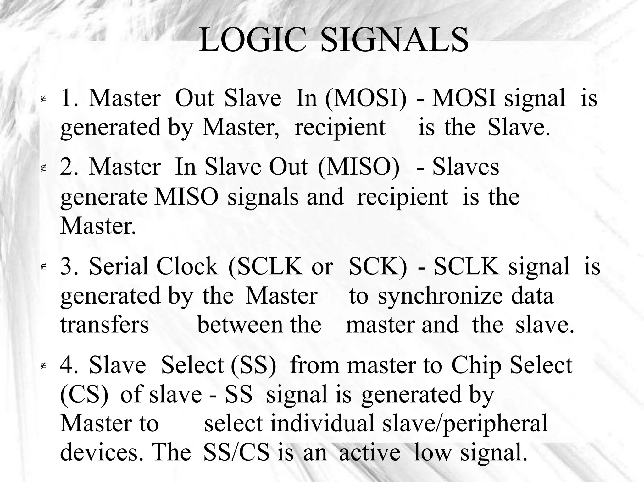
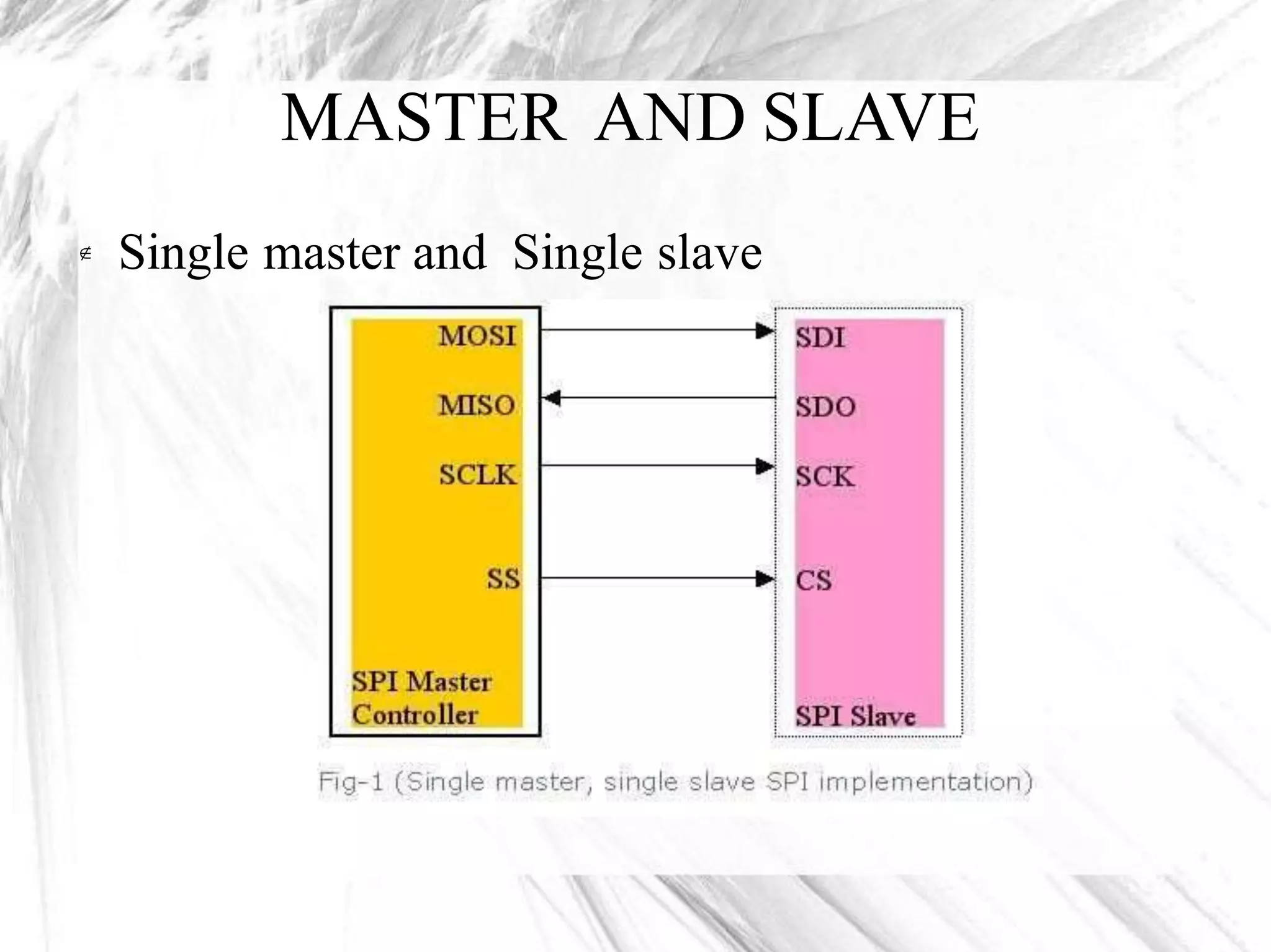
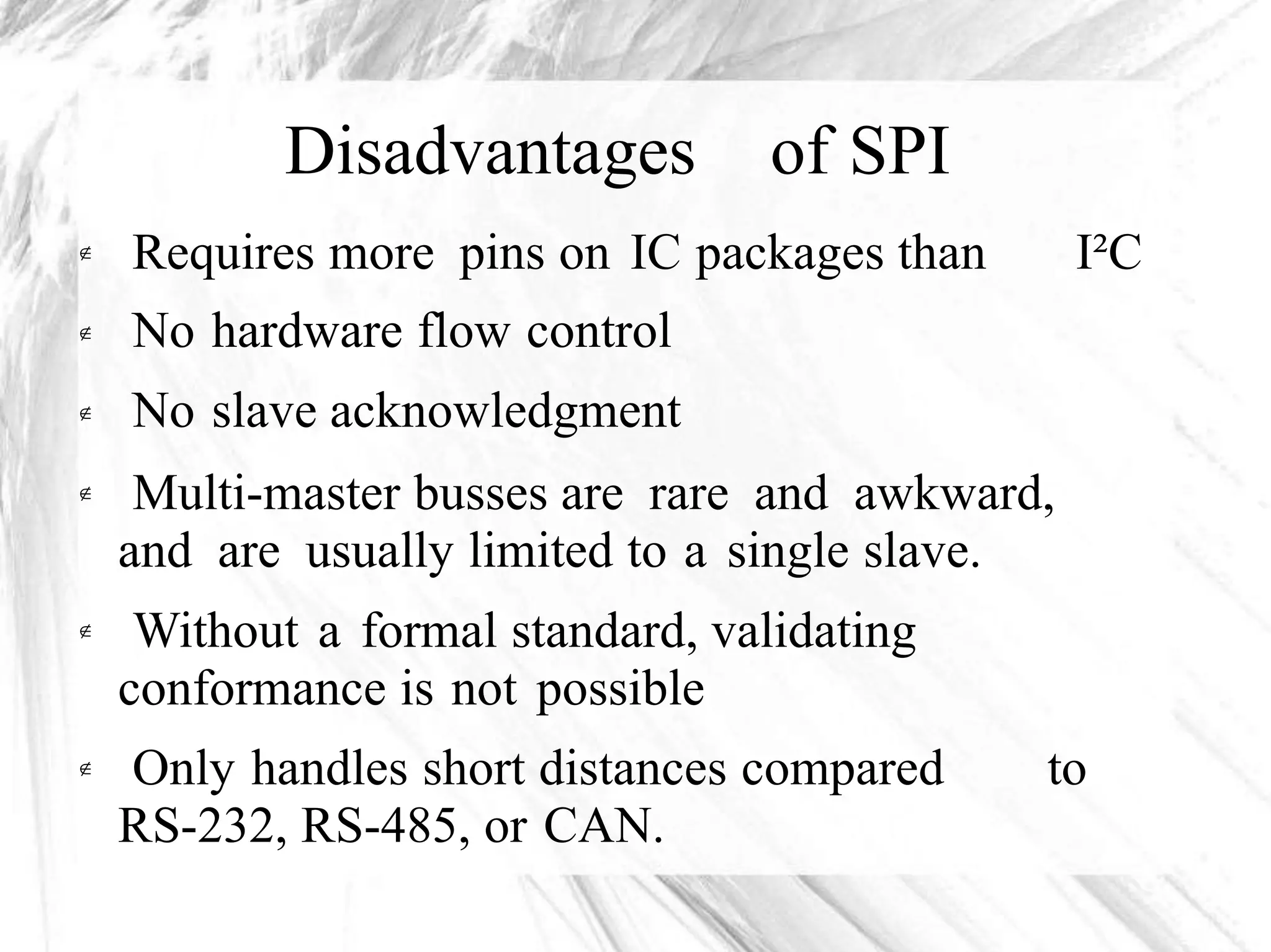
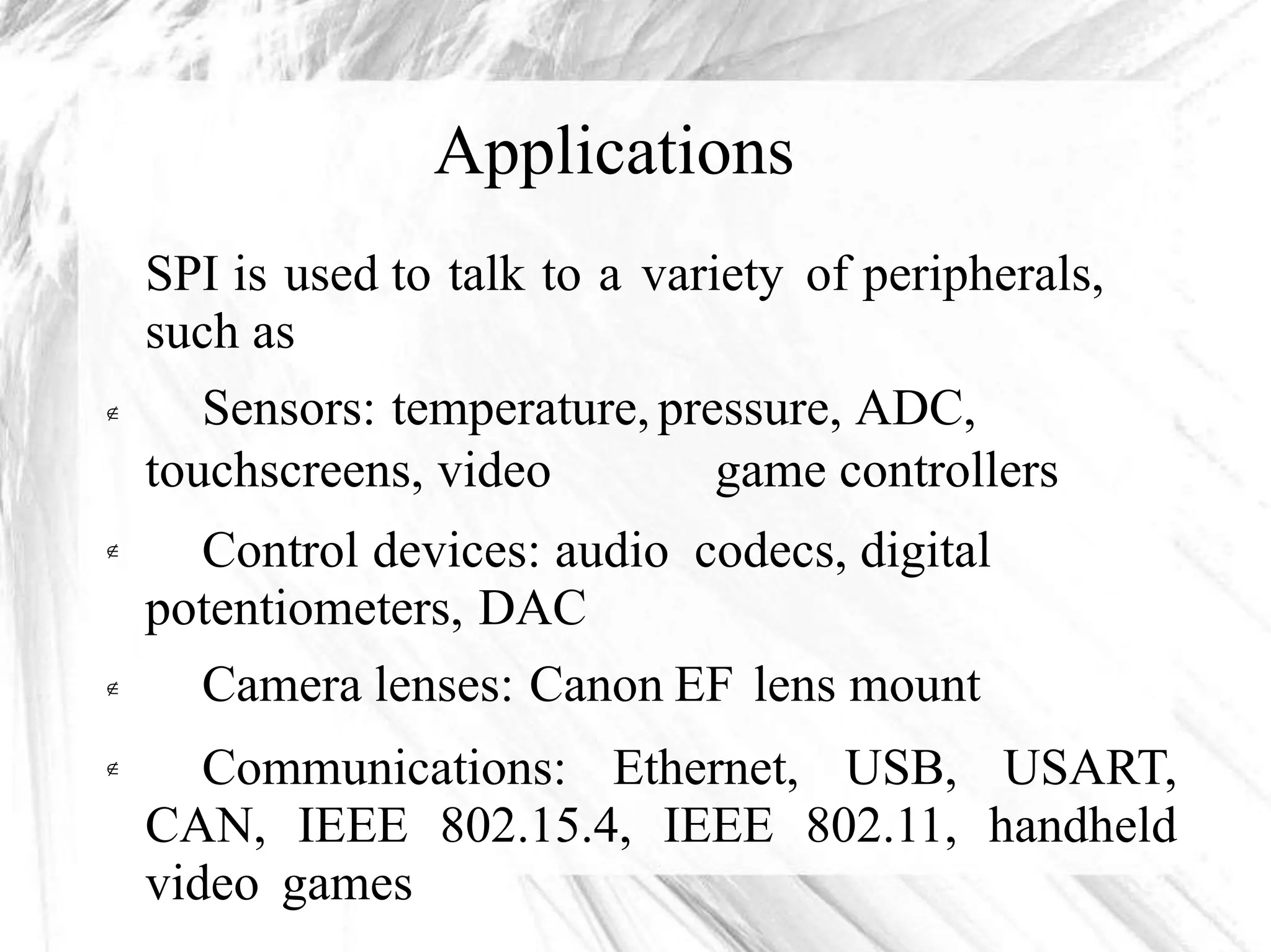
The Serial Peripheral Interface (SPI) bus is a
synchronous serial communication interface
specification used for short distance
communication, primarily in embedded systems.
The Serial Peripheral Interface or SPI-bus is a
simple 4-wire serial communications interface
used by many microprocessor/microcontroller
peripheral chips that enables the controllers and
peripheral devices to communicate each other.
Serial to Peripheral Interface (SPI) is a
hardware/firmware communications protocol



The SPI bus, operates at full duplex (means,
signals carrying data can go in both directions
simultaneously).
The SPI Bus is usuallyused only on the PCB.
The SPI Bus was designed to transfer data
between various IC chips, at very high speeds.
Typical applications include Secure Digital
cards and liquid crystal displays.





LOGIC SIGNALS
1. Master Out Slave In (MOSI)
generated by Master, recipient
2. Master In Slave Out (MISO)
- MOSI signal
is the Slave.
- Slaves
is

generate MISO signals and recipient is the
Master.
3. Serial Clock (SCLK or
generated by the Master
SCK) - SCLK signal
to synchronize data
is
transfers between the master and the slave.
4. Slave Select (SS) from master to Chip Select
(CS) of slave - SS signal is generated by

Master to select individual slave/peripheral
devices. The SS/CS is an active low signal.
MASTER AND SLAVE
Single master and Single slave
DATATRANSMISSION
Among these four logic signals, two of them
MOSI & MISO can be grouped as data lines
and other two SS & SCLK as control lines.

In SPI-bus communication there can be
master with multiple slaves.
Master selects only one slave at a time. If
device is not selected,it goes to high
impedance state (disconnected).
one


How do they communicate:
The communication is initiated by the master all the time.
The master first configures the clock, using a frequency, which is
less than or equal to the maximum frequency that the slave device
supports.
The master then select the desired slave for communication by
pulling the chip select (SS) line of that particular slave- peripheral
to "low" state.



A full duplex data transmission can occur during
cycle
That means the master sends a bit on the MOSI
reads it from that same line and the slave sends
each clock
line; the slave
a bit on the

MISO line; the master reads it from that same line.
DATA TRANSMISSION
Transmissions normally involve two shift
registers of some given word size, such as
eight bits.
Data is usually shifted out with the most-
significant bit first, while shifting a new less-
significant bit into the same register.
Data from the counterpart is shifted into the
least-significant bit register.
If more data needs to be exchanged, the shift
registers are reloaded and the process repeats.




Clock polarity and phase
In addition to setting the clock frequency, the
master must also configure the clock polarity
and phase with respect to the data.
Since the clock serves as synchronizationof the
data communication, there are four possible
modes that can be used in an SPI protocol,
based on this CPOL and CPHA.
At CPOL=0 the base value of the clock is



zero,i.e. the active state is 1 and idle state
0.
For CPHA=0, data are captured on the
is

At CPOL=1 the base value of the clock is one
(inversion of CPOL=0), i.e. the active state is 0
and idle state is 1.

For
falling
For
CPHA=0,
edge and
CPHA=1,
data
data
data
are captured on clock's
is output on a rising edge.
are captured on clock's


rising edge and data is output on a falling edge.

Types of configurations:
Suppose a master-microcontroller needs to talk
to multiple SPI Peripherals. There are 2 ways to
set thingsup:
1. Cascaded slaves or daisy-chained slaves
2. Independent slaves or parallel configuration



Daisy-chained slave configuration:
Daisy-chained slave configuration
In cascaded slave configuration, all the clock
lines (SCLK) are connected together.
all the chip select (CS) pins are connected
together.
The data output of the preceding slave-device is
tied to the data input of the next, thus forming a
wider shift register.
So the cascaded slave-devices are evidently
looked at as one larger device and receive
therefore the same chip select signal.





Independent slave configuration:
This is the typical SPI-bus configuration with
one SPI-master and multiple
slaves/peripherals. In this independent or
parallel slave configuration,

1. All the
together.
2. All the
together.
3. All the
together.
clock lines (SCLK) are connected
MISO data lines are connected
MOSI data lines are connected
4. But the Chip Select (CS) pin from each
Advantages of SPI
1.
2.
3.
Full duplex communication
Higher throughput
Not limited to 8-bit
than I²C protocol
words in the case

of bit-
transferring
4. Arbitrary choice of
and purpose
message size, contents,
5. Simple hardware interfacing
6. Typically lower power requirements than I²C
due to less circuitry.


7. No associated failure modes.
Disadvantages of SPI
Requires more pins on IC packages than
No hardware flow control
No slave acknowledgment
I²C


Multi-master busses are rare and awkward,
and are usually limited to a single slave.
Without a formal standard, validating
conformance is not possible


Only handles short distances compared
RS-232, RS-485, or CAN.
to
Applications
SPI is used to talk to a variety of peripherals,
such as
Sensors: temperature, pressure, ADC,
touchscreens, video game controllers
Control devices: audio codecs, digital
potentiometers, DAC
Camera lenses: Canon EF lens mount
Communications: Ethernet, USB, USART,
CAN, IEEE 802.15.4, IEEE 802.11, handheld
video games



Serial peripheral Interface - Embedded System Protocol

Serial peripheral Interface - Embedded System Protocol

  • 1.
    Serial Peripheral InterfaceBUS PRESENTED BY ADITYA
  • 2.
    INTRODUCTION The Serial PeripheralInterface (SPI) bus is a synchronous serial communication interface specification used for short distance communication, primarily in embedded systems. The Serial Peripheral Interface or SPI-bus is a simple 4-wire serial communications interface used by many microprocessor/microcontroller peripheral chips that enables the controllers and peripheral devices to communicate each other. Serial to Peripheral Interface (SPI) is a hardware/firmware communications protocol   
  • 3.
    The SPI bus,operates at full duplex (means, signals carrying data can go in both directions simultaneously). The SPI Bus is usuallyused only on the PCB. The SPI Bus was designed to transfer data between various IC chips, at very high speeds. Typical applications include Secure Digital cards and liquid crystal displays.     
  • 4.
    LOGIC SIGNALS 1. MasterOut Slave In (MOSI) generated by Master, recipient 2. Master In Slave Out (MISO) - MOSI signal is the Slave. - Slaves is  generate MISO signals and recipient is the Master. 3. Serial Clock (SCLK or generated by the Master SCK) - SCLK signal to synchronize data is transfers between the master and the slave. 4. Slave Select (SS) from master to Chip Select (CS) of slave - SS signal is generated by  Master to select individual slave/peripheral devices. The SS/CS is an active low signal.
  • 5.
    MASTER AND SLAVE Singlemaster and Single slave
  • 6.
    DATATRANSMISSION Among these fourlogic signals, two of them MOSI & MISO can be grouped as data lines and other two SS & SCLK as control lines.  In SPI-bus communication there can be master with multiple slaves. Master selects only one slave at a time. If device is not selected,it goes to high impedance state (disconnected). one  
  • 7.
    How do theycommunicate: The communication is initiated by the master all the time. The master first configures the clock, using a frequency, which is less than or equal to the maximum frequency that the slave device supports. The master then select the desired slave for communication by pulling the chip select (SS) line of that particular slave- peripheral to "low" state.    A full duplex data transmission can occur during cycle That means the master sends a bit on the MOSI reads it from that same line and the slave sends each clock line; the slave a bit on the  MISO line; the master reads it from that same line.
  • 8.
  • 9.
    Transmissions normally involvetwo shift registers of some given word size, such as eight bits. Data is usually shifted out with the most- significant bit first, while shifting a new less- significant bit into the same register. Data from the counterpart is shifted into the least-significant bit register. If more data needs to be exchanged, the shift registers are reloaded and the process repeats.    
  • 10.
    Clock polarity andphase In addition to setting the clock frequency, the master must also configure the clock polarity and phase with respect to the data. Since the clock serves as synchronizationof the data communication, there are four possible modes that can be used in an SPI protocol, based on this CPOL and CPHA. At CPOL=0 the base value of the clock is    zero,i.e. the active state is 1 and idle state 0. For CPHA=0, data are captured on the is 
  • 11.
    At CPOL=1 thebase value of the clock is one (inversion of CPOL=0), i.e. the active state is 0 and idle state is 1.  For falling For CPHA=0, edge and CPHA=1, data data data are captured on clock's is output on a rising edge. are captured on clock's   rising edge and data is output on a falling edge. 
  • 13.
    Types of configurations: Supposea master-microcontroller needs to talk to multiple SPI Peripherals. There are 2 ways to set thingsup: 1. Cascaded slaves or daisy-chained slaves 2. Independent slaves or parallel configuration   
  • 14.
  • 15.
    Daisy-chained slave configuration Incascaded slave configuration, all the clock lines (SCLK) are connected together. all the chip select (CS) pins are connected together. The data output of the preceding slave-device is tied to the data input of the next, thus forming a wider shift register. So the cascaded slave-devices are evidently looked at as one larger device and receive therefore the same chip select signal.     
  • 16.
  • 17.
    Independent slave configuration: Thisis the typical SPI-bus configuration with one SPI-master and multiple slaves/peripherals. In this independent or parallel slave configuration,  1. All the together. 2. All the together. 3. All the together. clock lines (SCLK) are connected MISO data lines are connected MOSI data lines are connected 4. But the Chip Select (CS) pin from each
  • 18.
    Advantages of SPI 1. 2. 3. Fullduplex communication Higher throughput Not limited to 8-bit than I²C protocol words in the case  of bit- transferring 4. Arbitrary choice of and purpose message size, contents, 5. Simple hardware interfacing 6. Typically lower power requirements than I²C due to less circuitry.   7. No associated failure modes.
  • 19.
    Disadvantages of SPI Requiresmore pins on IC packages than No hardware flow control No slave acknowledgment I²C   Multi-master busses are rare and awkward, and are usually limited to a single slave. Without a formal standard, validating conformance is not possible   Only handles short distances compared RS-232, RS-485, or CAN. to
  • 20.
    Applications SPI is usedto talk to a variety of peripherals, such as Sensors: temperature, pressure, ADC, touchscreens, video game controllers Control devices: audio codecs, digital potentiometers, DAC Camera lenses: Canon EF lens mount Communications: Ethernet, USB, USART, CAN, IEEE 802.15.4, IEEE 802.11, handheld video games   