3
SPI clocking: thereis no “standard way”
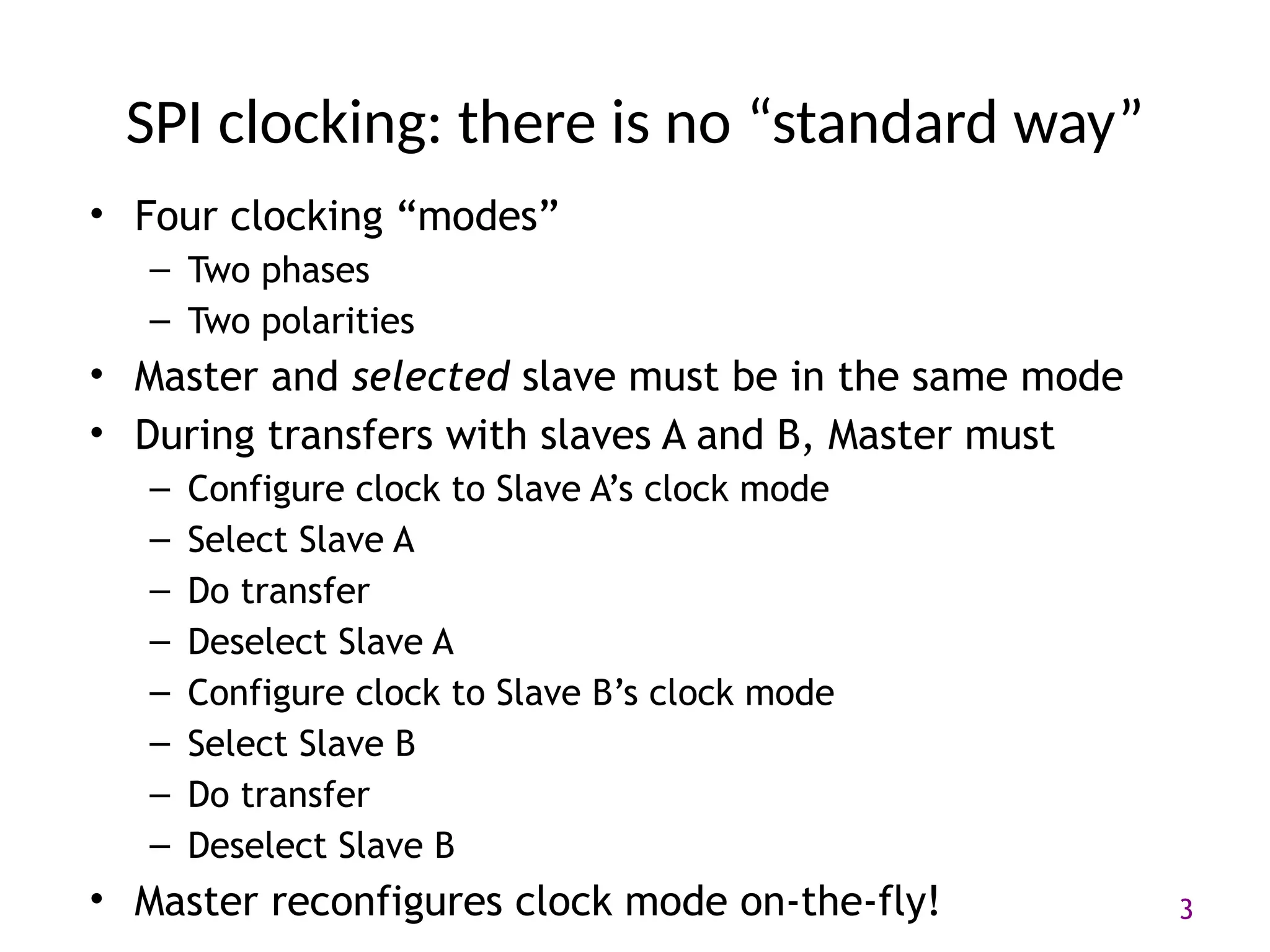
• Four clocking “modes”
– Two phases
– Two polarities
• Master and selected slave must be in the same mode
• During transfers with slaves A and B, Master must
– Configure clock to Slave A’s clock mode
– Select Slave A
– Do transfer
– Deselect Slave A
– Configure clock to Slave B’s clock mode
– Select Slave B
– Do transfer
– Deselect Slave B
• Master reconfigures clock mode on-the-fly!
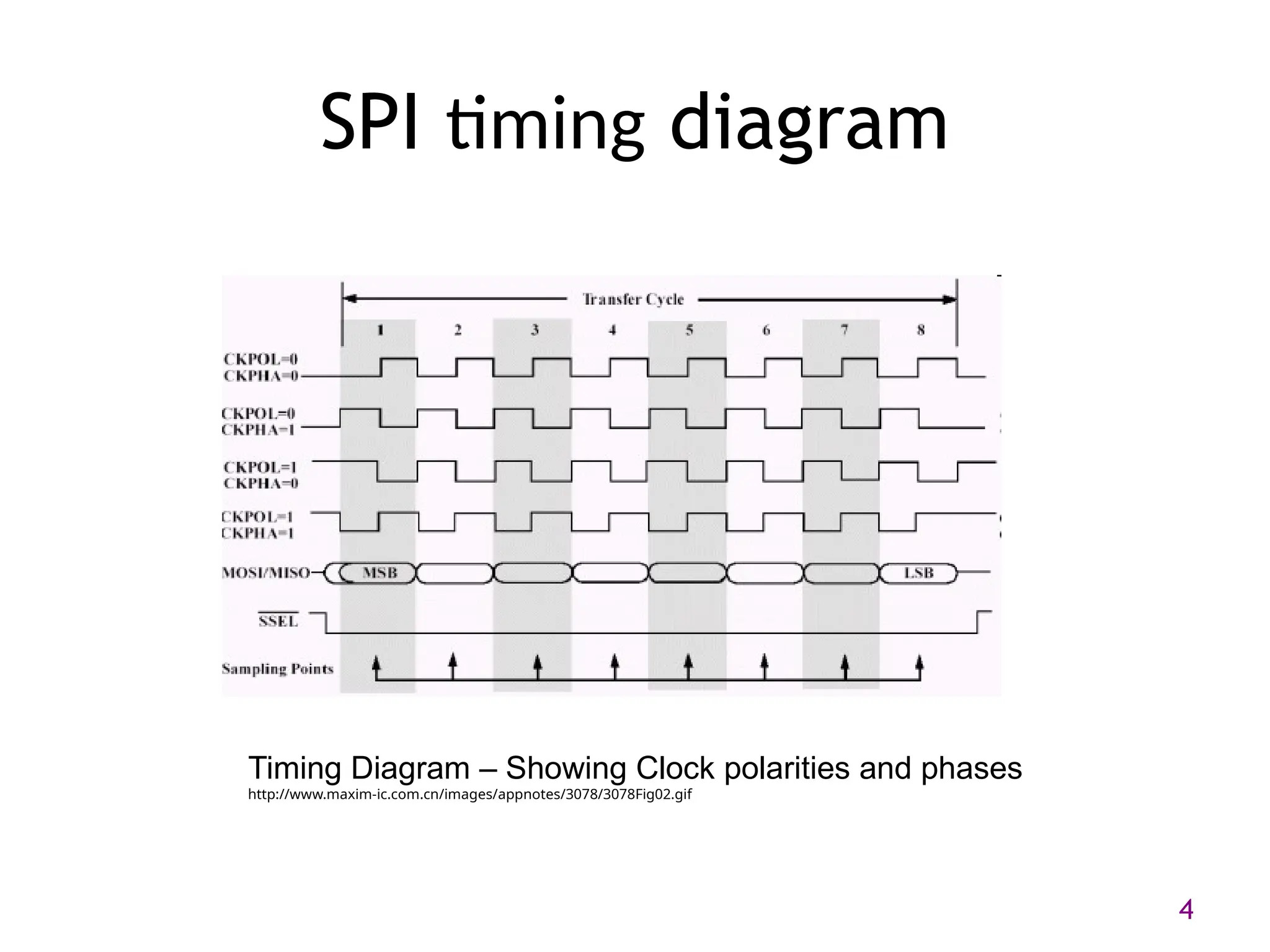
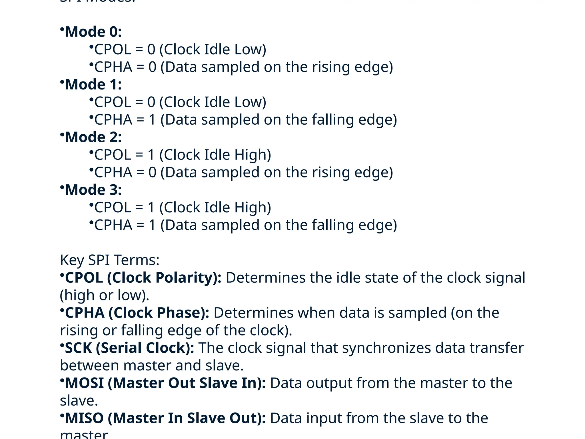
SPI Modes:
•Mode 0:
•CPOL= 0 (Clock Idle Low)
•CPHA = 0 (Data sampled on the rising edge)
•Mode 1:
•CPOL = 0 (Clock Idle Low)
•CPHA = 1 (Data sampled on the falling edge)
•Mode 2:
•CPOL = 1 (Clock Idle High)
•CPHA = 0 (Data sampled on the rising edge)
•Mode 3:
•CPOL = 1 (Clock Idle High)
•CPHA = 1 (Data sampled on the falling edge)
Key SPI Terms:
•CPOL (Clock Polarity): Determines the idle state of the clock signal
(high or low).
•CPHA (Clock Phase): Determines when data is sampled (on the
rising or falling edge of the clock).
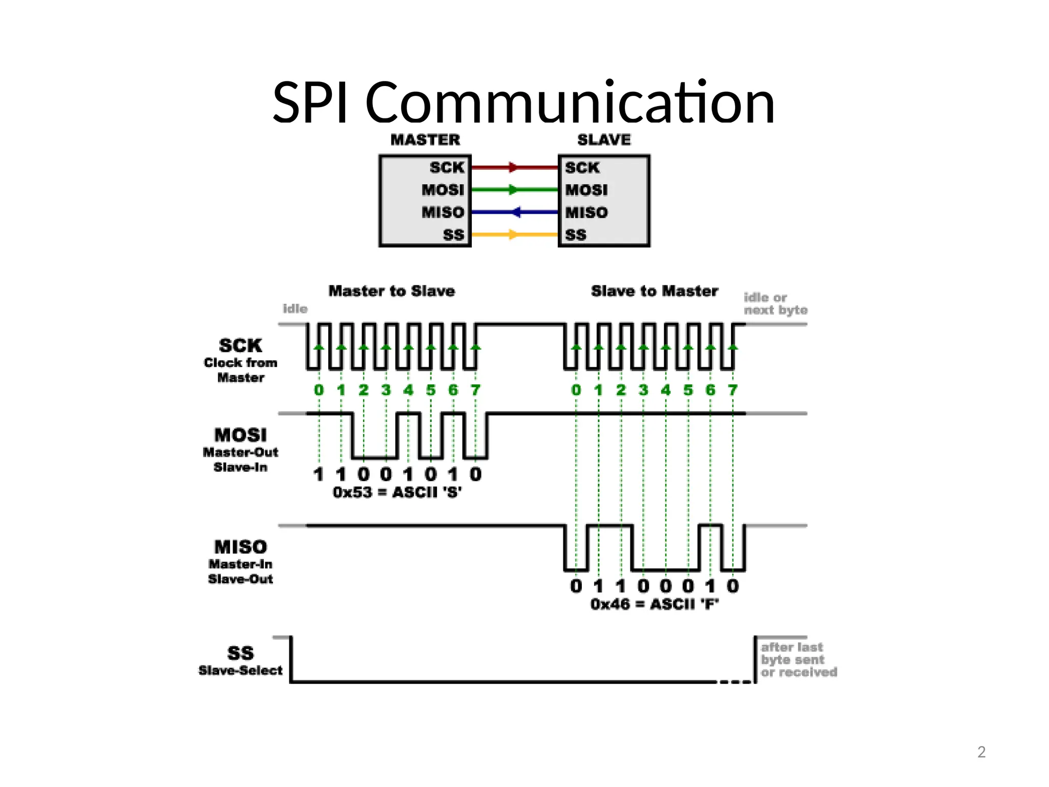
•SCK (Serial Clock): The clock signal that synchronizes data transfer
between master and slave.
•MOSI (Master Out Slave In): Data output from the master to the
slave.
•MISO (Master In Slave Out): Data input from the slave to the
6.
6
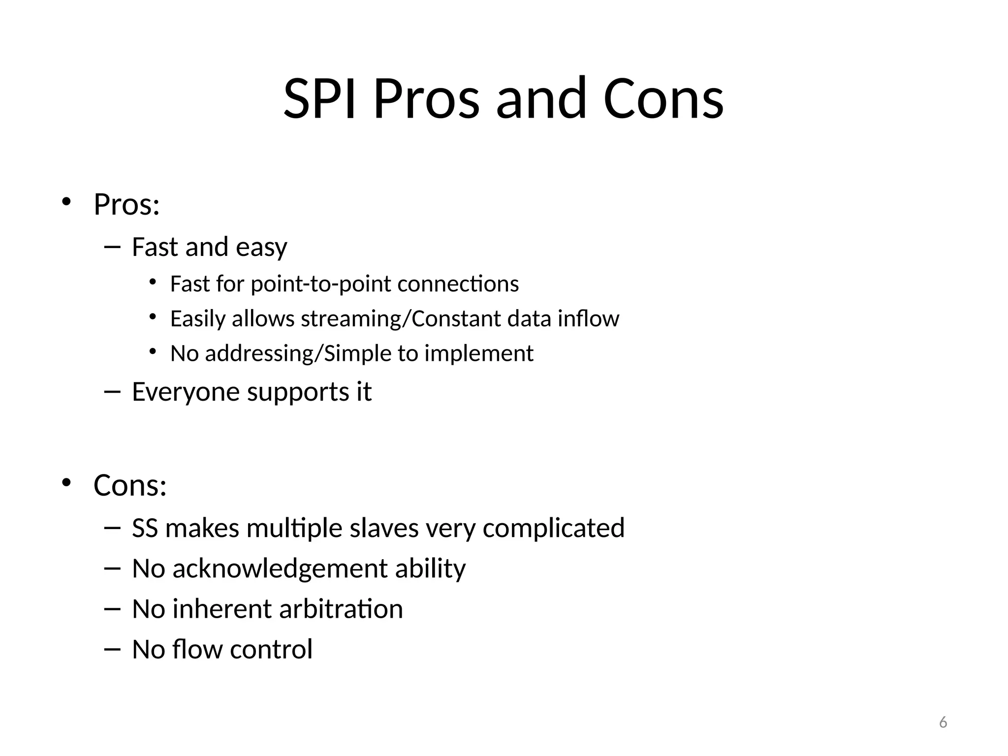
SPI Pros andCons
• Pros:
– Fast and easy
• Fast for point-to-point connections
• Easily allows streaming/Constant data inflow
• No addressing/Simple to implement
– Everyone supports it
• Cons:
– SS makes multiple slaves very complicated
– No acknowledgement ability
– No inherent arbitration
– No flow control
7.
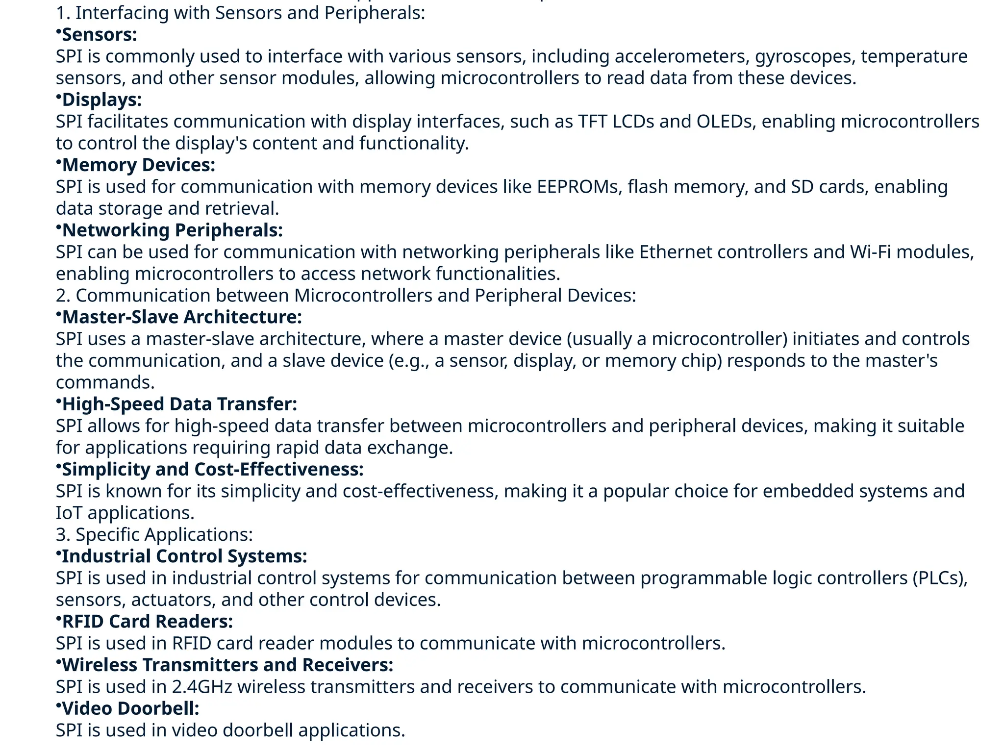
1. Interfacing withSensors and Peripherals:
•Sensors:
SPI is commonly used to interface with various sensors, including accelerometers, gyroscopes, temperature
sensors, and other sensor modules, allowing microcontrollers to read data from these devices.
•Displays:
SPI facilitates communication with display interfaces, such as TFT LCDs and OLEDs, enabling microcontrollers
to control the display's content and functionality.
•Memory Devices:
SPI is used for communication with memory devices like EEPROMs, flash memory, and SD cards, enabling
data storage and retrieval.
•Networking Peripherals:
SPI can be used for communication with networking peripherals like Ethernet controllers and Wi-Fi modules,
enabling microcontrollers to access network functionalities.
2. Communication between Microcontrollers and Peripheral Devices:
•Master-Slave Architecture:
SPI uses a master-slave architecture, where a master device (usually a microcontroller) initiates and controls
the communication, and a slave device (e.g., a sensor, display, or memory chip) responds to the master's
commands.
•High-Speed Data Transfer:
SPI allows for high-speed data transfer between microcontrollers and peripheral devices, making it suitable
for applications requiring rapid data exchange.
•Simplicity and Cost-Effectiveness:
SPI is known for its simplicity and cost-effectiveness, making it a popular choice for embedded systems and
IoT applications.
3. Specific Applications:
•Industrial Control Systems:
SPI is used in industrial control systems for communication between programmable logic controllers (PLCs),
sensors, actuators, and other control devices.
•RFID Card Readers:
SPI is used in RFID card reader modules to communicate with microcontrollers.
•Wireless Transmitters and Receivers:
SPI is used in 2.4GHz wireless transmitters and receivers to communicate with microcontrollers.
•Video Doorbell:
SPI is used in video doorbell applications.
8.
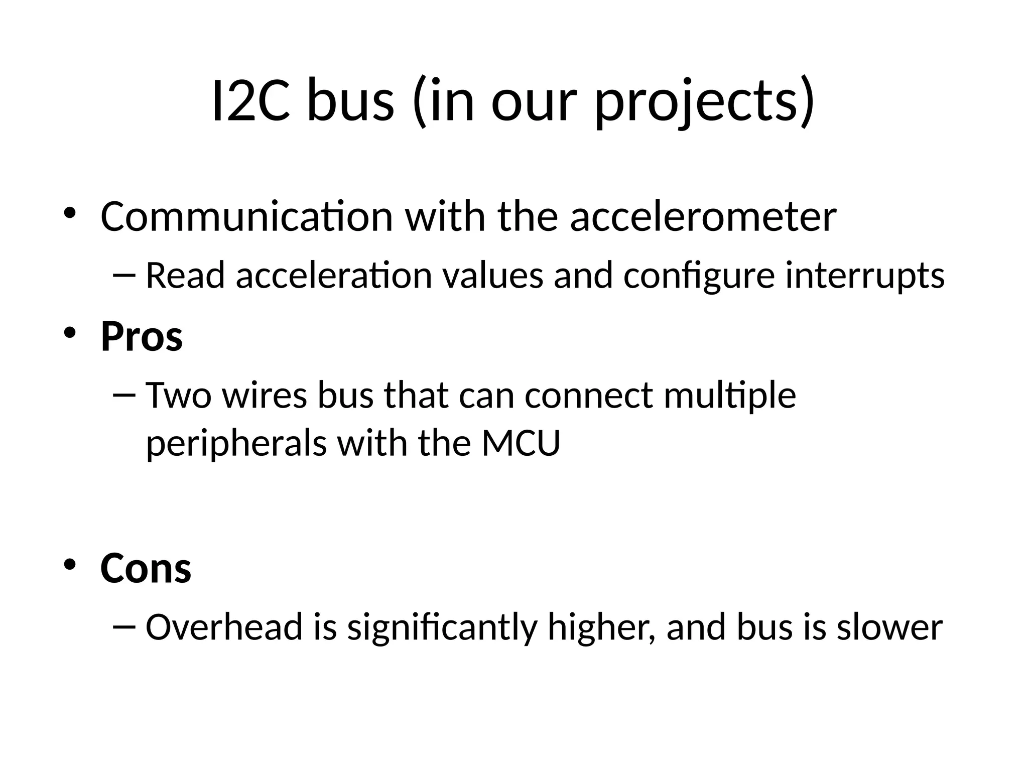
I2C bus (inour projects)
• Communication with the accelerometer
– Read acceleration values and configure interrupts
• Pros
– Two wires bus that can connect multiple
peripherals with the MCU
• Cons
– Overhead is significantly higher, and bus is slower
9.
I2C Details
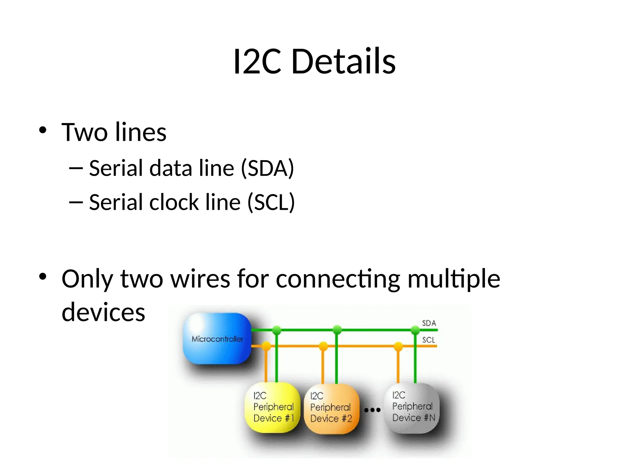
• Twolines
– Serial data line (SDA)
– Serial clock line (SCL)
• Only two wires for connecting multiple
devices
10.
I2C Details
• EachI2C device recognized by a unique address
• Each I2C device can be either a transmitter or receiver
• I2C devices can be masters or slaves for a data transfer
– Master (usually a microcontroller): Initiates a data transfer
on the bus, generates the clock signals to permit that
transfer, and terminates the transfer
– Slave: Any device addressed by the master at that time
11.
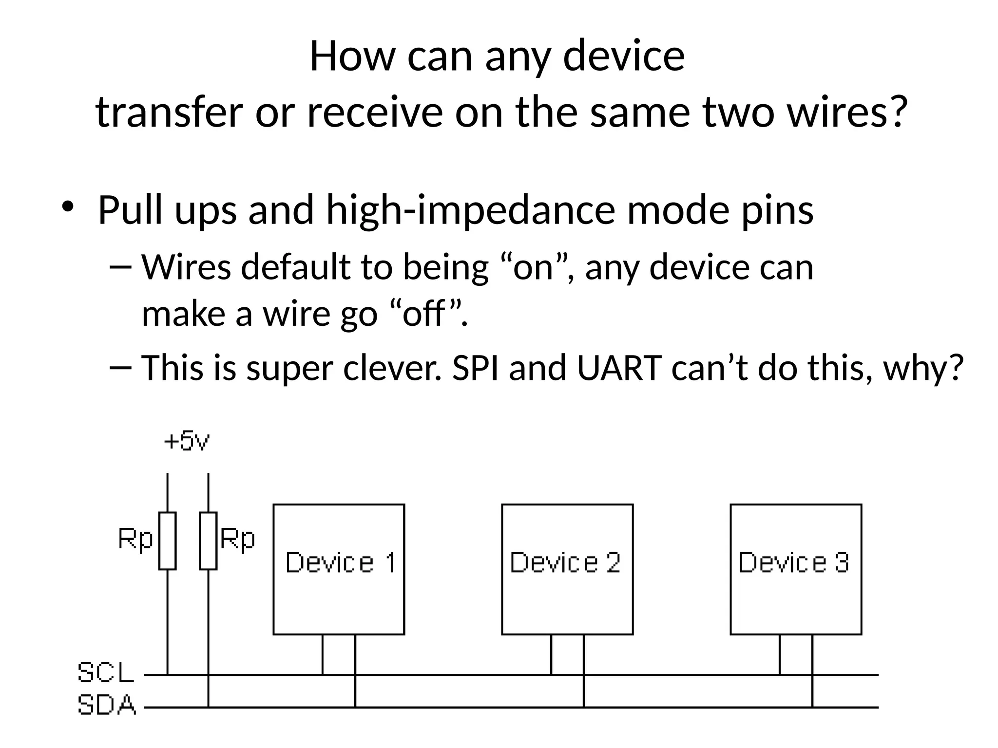
How can anydevice
transfer or receive on the same two wires?
• Pull ups and high-impedance mode pins
– Wires default to being “on”, any device can
make a wire go “off”.
– This is super clever. SPI and UART can’t do this, why?
12.
12 of 40
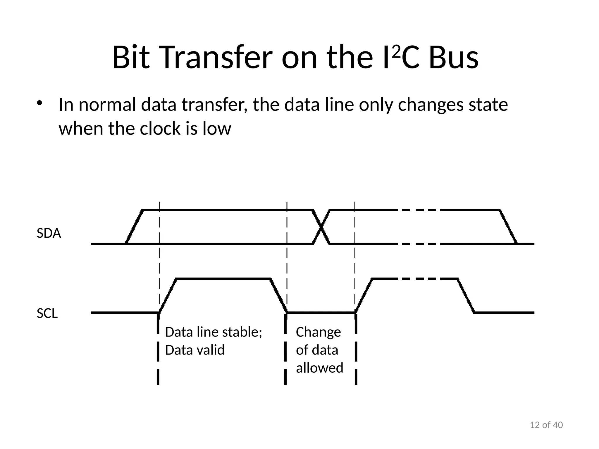
BitTransfer on the I2
C Bus
• In normal data transfer, the data line only changes state
when the clock is low
SDA
SCL
Data line stable;
Data valid
Change
of data
allowed
13.
13 of 40
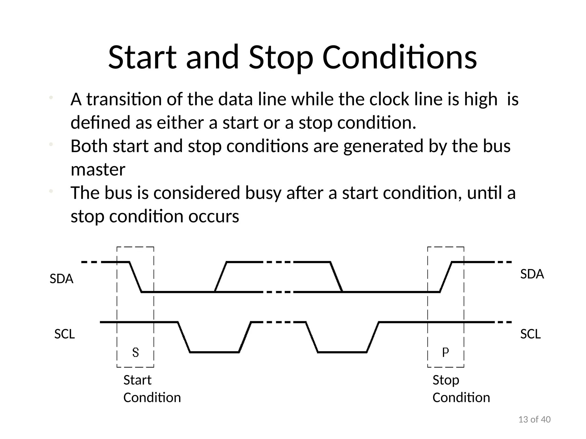
Startand Stop Conditions
• A transition of the data line while the clock line is high is
defined as either a start or a stop condition.
• Both start and stop conditions are generated by the bus
master
• The bus is considered busy after a start condition, until a
stop condition occurs
Start
Condition
Stop
Condition
SCL SCL
SDA
SDA
14.
14 of 40
I2
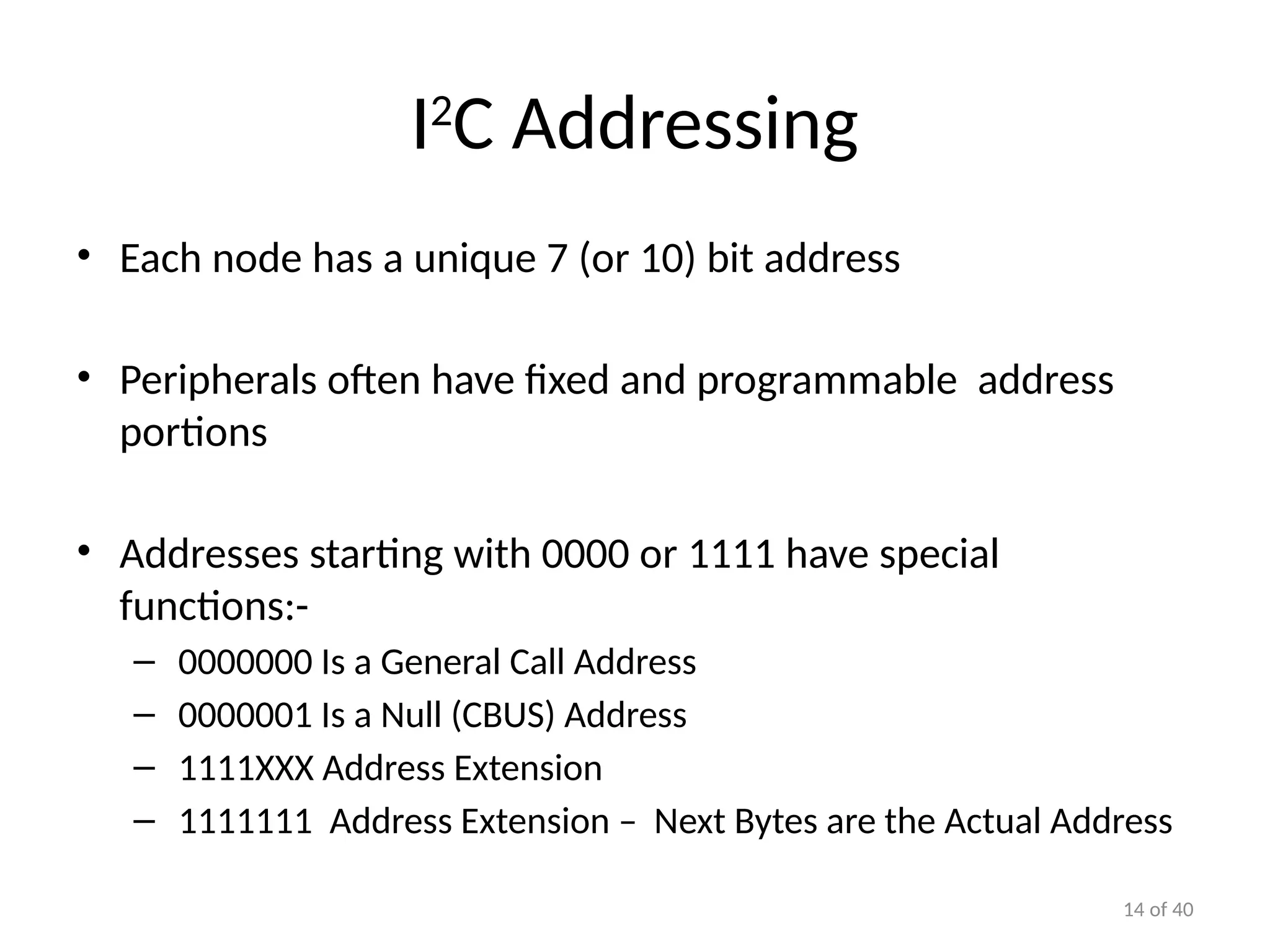
CAddressing
• Each node has a unique 7 (or 10) bit address
• Peripherals often have fixed and programmable address
portions
• Addresses starting with 0000 or 1111 have special
functions:-
– 0000000 Is a General Call Address
– 0000001 Is a Null (CBUS) Address
– 1111XXX Address Extension
– 1111111 Address Extension – Next Bytes are the Actual Address
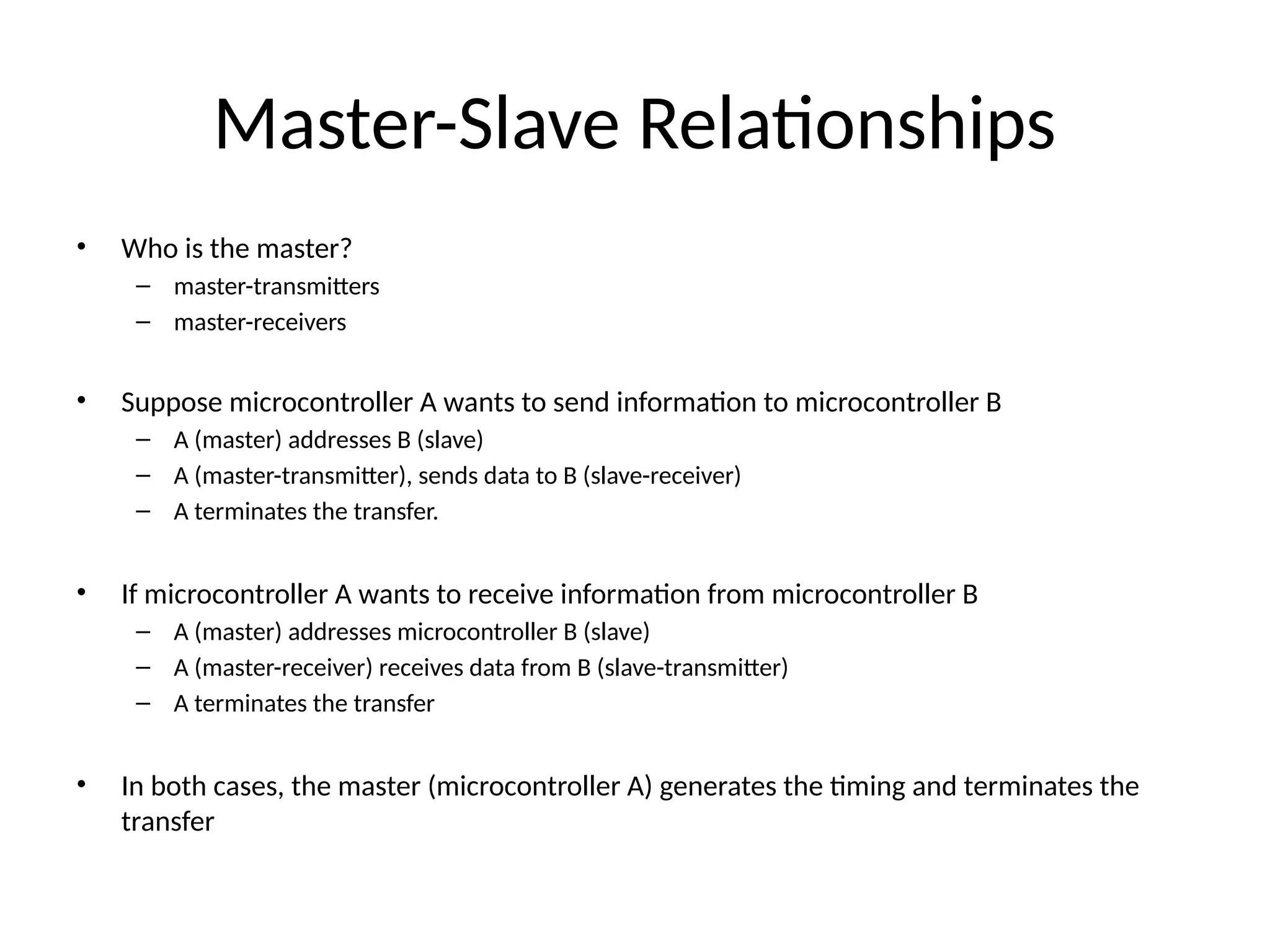
Master-Slave Relationships
• Whois the master?
– master-transmitters
– master-receivers
• Suppose microcontroller A wants to send information to microcontroller B
– A (master) addresses B (slave)
– A (master-transmitter), sends data to B (slave-receiver)
– A terminates the transfer.
• If microcontroller A wants to receive information from microcontroller B
– A (master) addresses microcontroller B (slave)
– A (master-receiver) receives data from B (slave-transmitter)
– A terminates the transfer
• In both cases, the master (microcontroller A) generates the timing and terminates the
transfer
17.
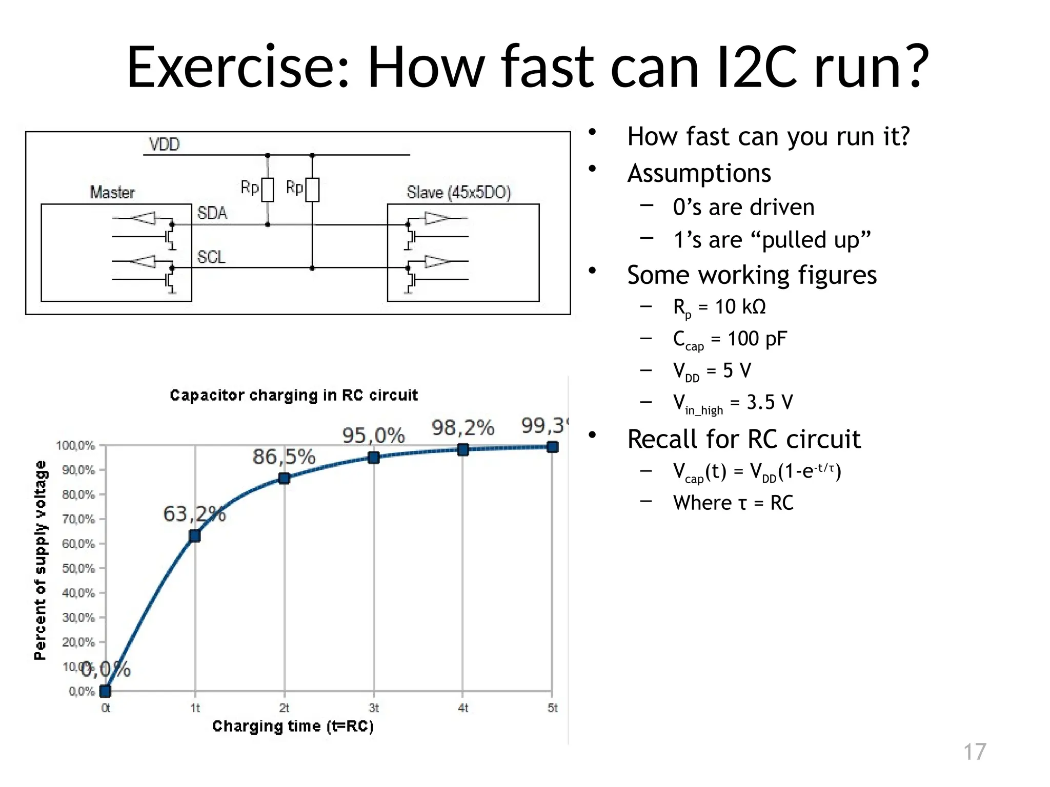
Exercise: How fastcan I2C run?
17
• How fast can you run it?
• Assumptions
– 0’s are driven
– 1’s are “pulled up”
• Some working figures
– Rp = 10 kΩ
– Ccap = 100 pF
– VDD = 5 V
– Vin_high = 3.5 V
• Recall for RC circuit
– Vcap(t) = VDD(1-e-t/τ
)
– Where τ = RC
18.
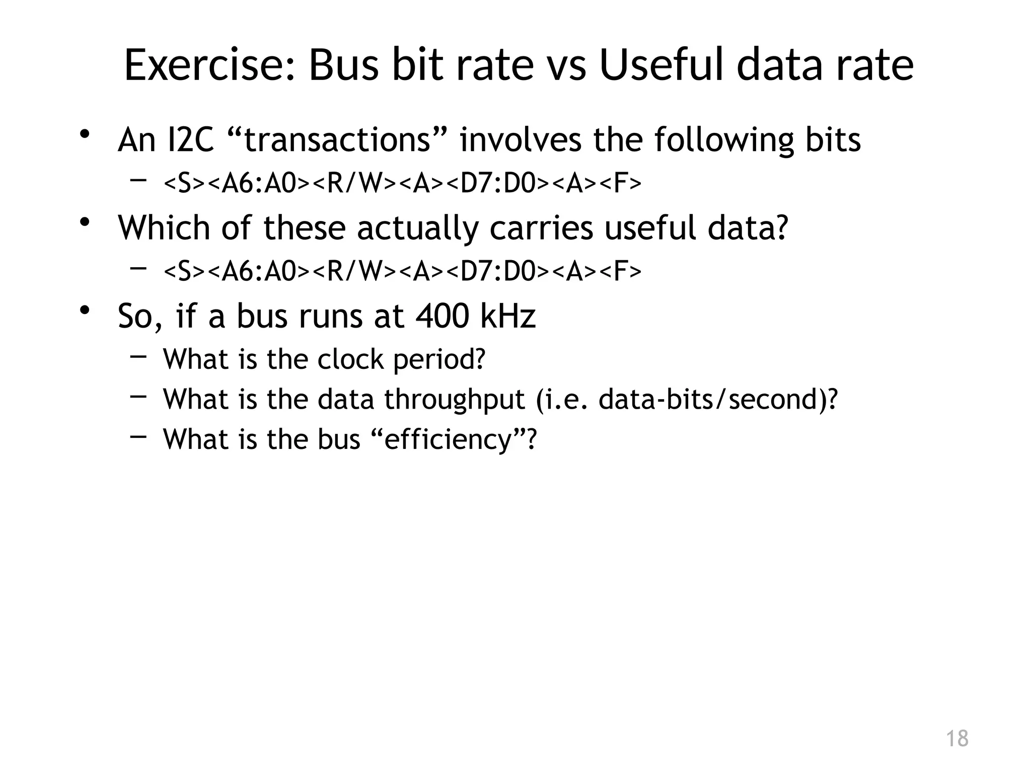
Exercise: Bus bitrate vs Useful data rate
18
• An I2C “transactions” involves the following bits
– <S><A6:A0><R/W><A><D7:D0><A><F>
• Which of these actually carries useful data?
– <S><A6:A0><R/W><A><D7:D0><A><F>
• So, if a bus runs at 400 kHz
– What is the clock period?
– What is the data throughput (i.e. data-bits/second)?
– What is the bus “efficiency”?
19.
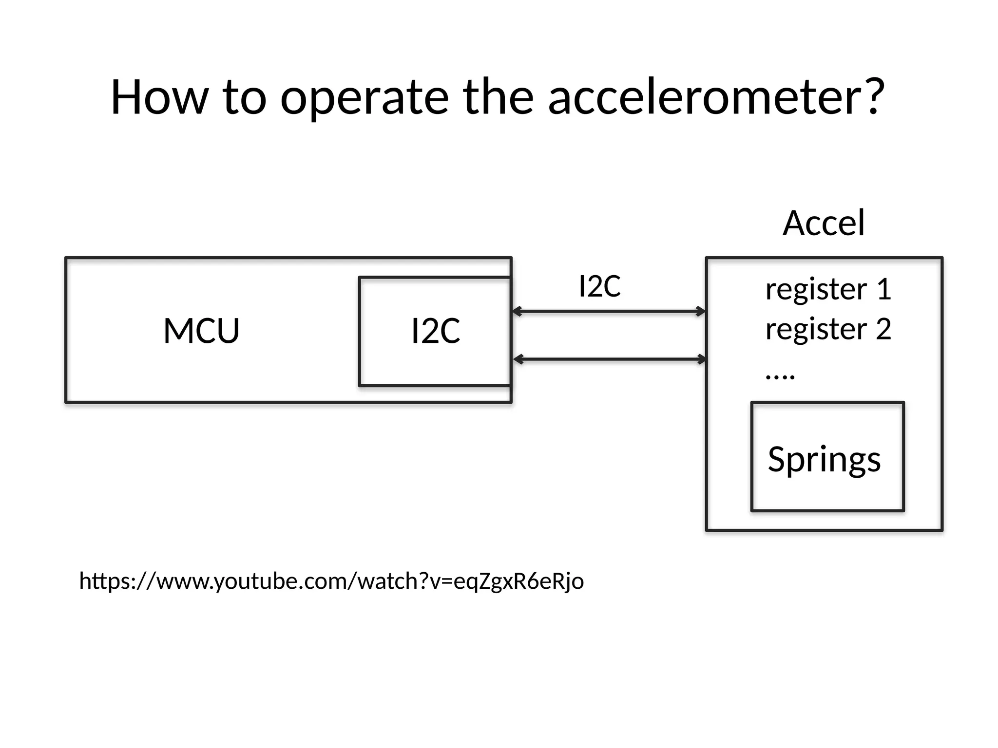
How to operatethe accelerometer?
MCU
Accel
I2C
I2C
register 1
register 2
….
Springs
https://www.youtube.com/watch?v=eqZgxR6eRjo


![Communication_Protocols[2][1].pptx on protocoals](https://cdn.slidesharecdn.com/ss_thumbnails/communicationprotocols21-250429164707-38355411-thumbnail.jpg?width=640&height=640&fit=bounds)


