The document provides an overview of various communication interfaces used in embedded systems, focusing on protocols like I2C, SPI, and UART. It details the functionalities, advantages, and disadvantages of these communication methods, including how they manage data transmission, device communication, and error checking. Additionally, it compares the characteristics of I2C and SPI and discusses the UART's role in asynchronous serial communication.
![1.INTER INTEGRATED CIRCUIT BUS[I2C bus] - contents
I2C bus
Introduction
BUS Lines
I2C Protocols
I2C related terms
Repeated Start Condition
Clock Stretching
Acknowledge (ACK) and Not Acknowledge (NACK)
10-bit Addresses
Advantages of I2C
Disadvantages of I2C
Applications of I2C](https://image.slidesharecdn.com/embeddedsystemonboardcommunication-240923105523-165d9ac6/75/embedded-system-on-board-communication-pptx-4-2048.jpg)
![1.INTER INTEGRATED CIRCUIT BUS[I2C bus]
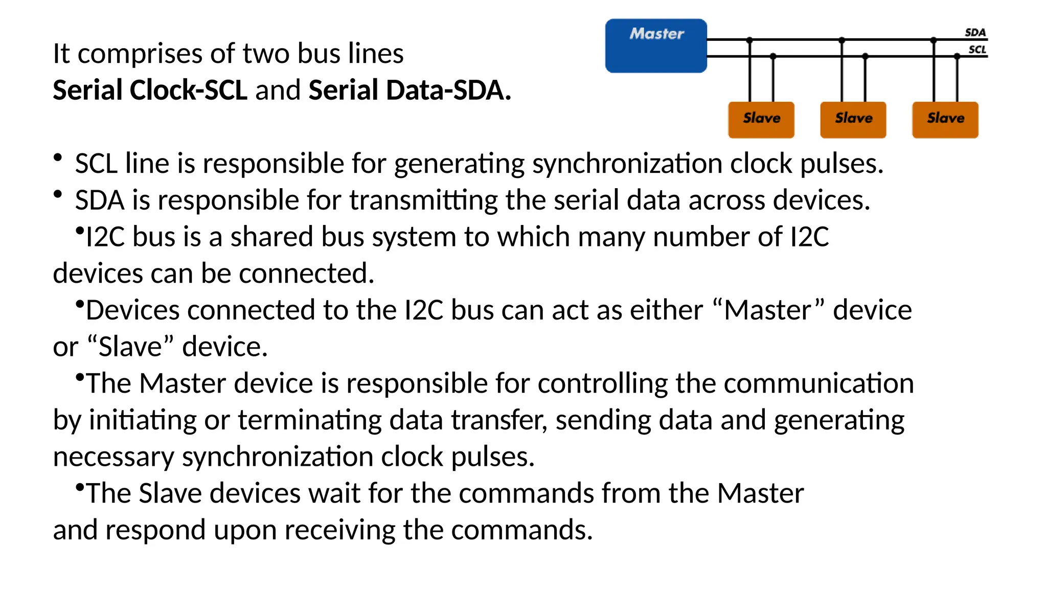
It is a synchronous bi-directional half duplex two –
wire serial bus which provides communication link
between integrated circuits.
It was designed by Philips Semiconductors in
1980s.
It was developed to provide an easy way of
connection between a microprocessor /
microcontroller system and low speed peripheral
chips/Ic](https://image.slidesharecdn.com/embeddedsystemonboardcommunication-240923105523-165d9ac6/75/embedded-system-on-board-communication-pptx-5-2048.jpg)


![1.INTER INTEGRATED CIRCUIT BUS[I2C bus] - contents
I2C bus
Introduction
BUS Lines
I2C Protocols
I2C related terms
Repeated Start Condition
Clock Stretching
Acknowledge (ACK) and Not Acknowledge (NACK)
10-bit Addresses
Advantages of I2C
Disadvantages of I2C
Applications of I2C](https://crownmelresort.com/image.slidesharecdn.com/embeddedsystemonboardcommunication-240923105523-165d9ac6/75/embedded-system-on-board-communication-pptx-4-2048.jpg)
![1.INTER INTEGRATED CIRCUIT BUS[I2C bus]
It is a synchronous bi-directional half duplex two –
wire serial bus which provides communication link
between integrated circuits.
It was designed by Philips Semiconductors in
1980s.
It was developed to provide an easy way of
connection between a microprocessor /
microcontroller system and low speed peripheral
chips/Ic](https://crownmelresort.com/image.slidesharecdn.com/embeddedsystemonboardcommunication-240923105523-165d9ac6/75/embedded-system-on-board-communication-pptx-5-2048.jpg)