Downloaded 27 times
![Disclosure to Promote the Right To Information
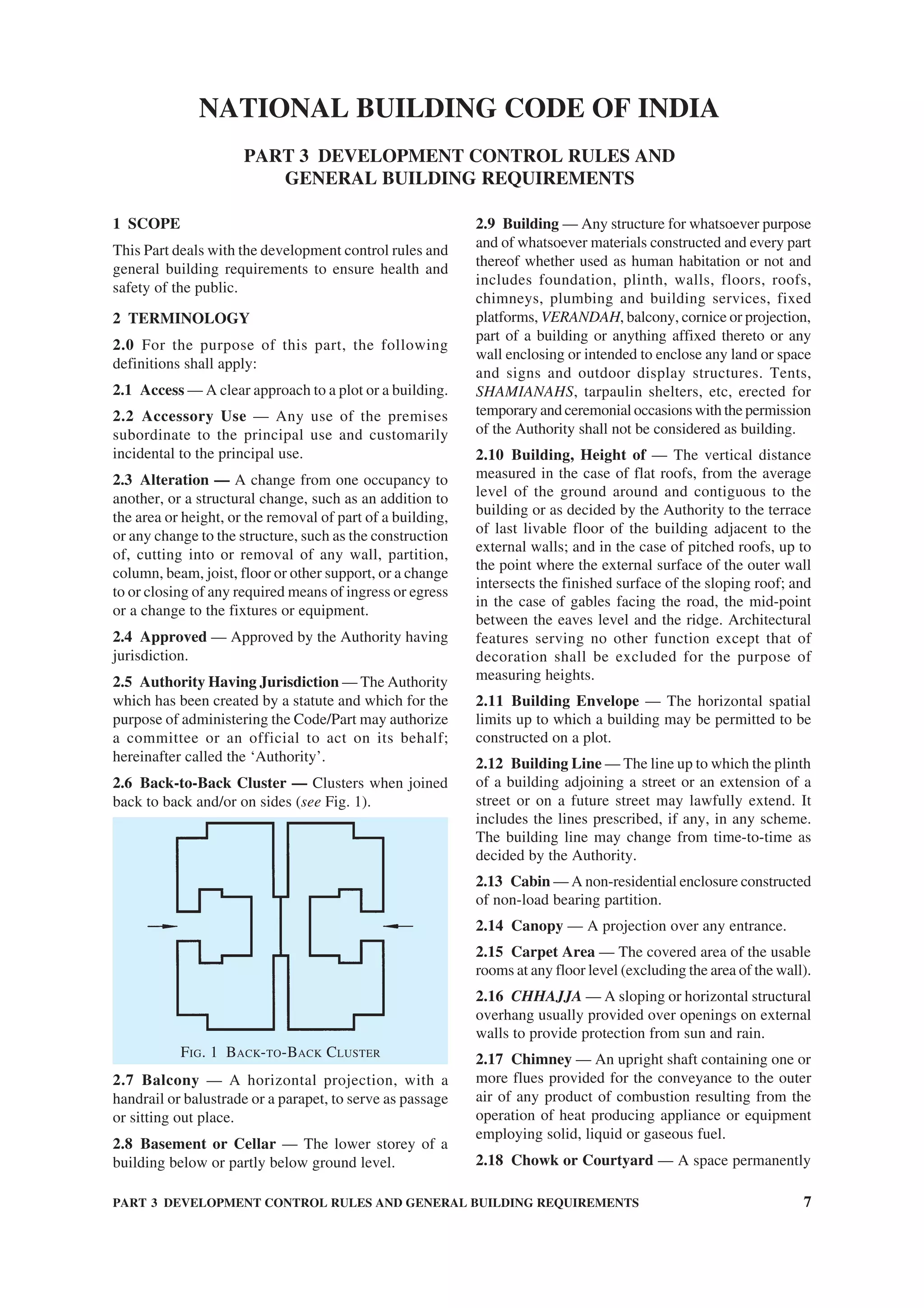
Whereas the Parliament of India has set out to provide a practical regime of right to
information for citizens to secure access to information under the control of public authorities,
in order to promote transparency and accountability in the working of every public authority,
and whereas the attached publication of the Bureau of Indian Standards is of particular interest
to the public, particularly disadvantaged communities and those engaged in the pursuit of
education and knowledge, the attached public safety standard is made available to promote the
timely dissemination of this information in an accurate manner to the public.
इंटरनेट मानक
“!ान $ एक न' भारत का +नम-ण”
Satyanarayan Gangaram Pitroda
“Invent a New India Using Knowledge”
“प0रा1 को छोड न' 5 तरफ”
Jawaharlal Nehru
“Step Out From the Old to the New”
“जान1 का अ+धकार, जी1 का अ+धकार”
Mazdoor Kisan Shakti Sangathan
“The Right to Information, The Right to Live”
“!ान एक ऐसा खजाना > जो कभी च0राया नहB जा सकता है”
Bhartṛhari—Nītiśatakam
“Knowledge is such a treasure which cannot be stolen”
“Invent a New India Using Knowledge”
है”ह”ह
SP 7 : Group 1 (2005): NATIONAL BUILDING CODE OF INDIA 2005
GROUP 1 [CED 46: National Building Code]](https://image.slidesharecdn.com/is-200203030013/75/NATIONAL-BUILDING-CODE-SP7-1-2048.jpg)


![( ix )
Organization Representative(s)
Indian Institute of Technology (Centre for Energy Studies), PROF N. K. BANSAL
New Delhi
Indian Roads Congress, New Delhi CHIEF ENGINEER (DESIGN), CPWD
SUPERINTENDING ENGINEER (DESIGN), CPWD (Alternate)
Institute of Town Planners, India, New Delhi DR S. K. KULSHRESTHA
Institution of Fire Engineers (India), New Delhi PRESIDENT
GENERAL SECRETARY (Alternate)
Ministry of Home Affairs, New Delhi FIRE ADVISOR
Ministry of Home Affairs (Disaster Management Division), SHRI M. P. SAJNANI
New Delhi SHRI S. K. SWAMI (Alternate)
Ministry of Non-Conventional Energy Sources, New Delhi DR T. C. TRIPATHI
Ministry of Road Transport and Highways, New Delhi SHRI S. B. BASU
SHRI P. HALDER (Alternate)
Municipal Corporation of Greater Mumbai, Mumbai DIRECTOR (ENGG SERVICES & PROJECTS)
CITY ENGINEER (Alternate)
National Buildings Construction Corporation, New Delhi SHRI B. PRASAD
SHRI N. P. AGARWAL (Alternate)
National Council for Cement and Building Materials, Ballabgarh SHRI SHIBAN RAINA
DR ANIL KUMAR (Alternate)
National Design and Research Forum, The Institution of Engineers PROF R. NARAYANA IYENGAR
(India), Bangalore SHRI B. SURESH (Alternate)
National Environmental Engineering Research Institute (CSIR), DR ARINDAM GHOSH
Nagpur DR V. P. DESHPANDE (Alternate)
North Eastern Council, Shillong SHRI P. K. DEB
Public Works Department (Roads and Buildings), Gandhinagar SHRI V. P. JAMDAR
SHRI M. S. JALLUNDHWALA (Alternate)
Research, Designs and Standards Organization (Ministry of Railways), SHRI R. K. GUPTA
Lucknow SHRI J. P. DAS (Alternate)
School of Planning and Architecture, New Delhi DIRECTOR
Structural Engineering Research Centre (CSIR), Chennai SHRI C. V. VAIDYANATHAN
SHRI K. MANI (Alternate)
Suri and Suri Consulting Acoustical Engineers, New Delhi SHRI GAUTAM SURI
The Energy and Resources Institute, New Delhi MS MILI MAJUMDAR
MS VIDISHA SALUNKE-PALSULE (Alternate)
The Indian Institute of Architects, New Delhi SHRI BALBIR VERMA
SHRI ABHIJIT RAY (Alternate)
The Institution of Engineers (India), Kolkata PROF G. P. LAL
SHRI O. P. GOEL (Alternate)
The Institution of Surveyors, New Delhi SHRI K. S. KHARB
SHRI R. K. BHALLA (Alternate)
Town and Country Planning Organization, New Delhi SHRI K. T. GURUMUKHI
SHRI J. B. KSHIRSAGAR (Alternate)
U.P. Housing and Development Board, Lucknow SHRI HARI GOPAL
Unitech Ltd, Gurgaon SHRI SUSHIL SHARMA
SHRI SHAHID MAHMOOD (Alternate)
In personal capacity (5, Sunder Nagar, New Delhi 110 003) DR J. R. BHALLA
BIS Directorate General SHRI S. K. JAIN, Director & Head (Civil Engineering)
[Representing Director General (Ex-officio Member)]
Member Secretary
SHRI SANJAY PANT
Joint Director (Civil Engineering), BIS](https://image.slidesharecdn.com/is-200203030013/75/NATIONAL-BUILDING-CODE-SP7-11-2048.jpg)

![( xiii )
Important Explanatory Note for Users of Code
In this Code, where reference is made to ‘accepted standards’ in relation to material
specification, testing or other related information or where reference is made to ‘good practice’
in relation to design, constructional procedures or other related information, the Indian
Standards listed at the end of the concerned Parts/Sections may be used to the interpretation
of these terms.
At the time of publication, the editions indicated in the above Indian Standards were valid.
All standards are subject to revision and parties to agreements based on the Parts/Sections
are encouraged to investigate the possibility of applying the most recent editions of the
standards.
In the list of standards given at the end of each Part/Section, the number appearing in the
first column indicates the number of the reference in that Part/Section. For example:
a) accepted standard [3(1)] refers to the standard given at serial number 1 of the list of
standards given at the end of Part 3, that is IS 8888 (Part 1) : 1993 ‘Guide for
requirements of low income housing: Part 1 Urban area (first revision)’.
b) good practice [4(3)] refers to the standard given at serial number 3 of the list of standards
given at the end of Part 4, that is IS 15394 : 2003 ‘Code of practice for fire safety in
petroleum refinery and fertilizer plants’.
c) accepted standard [4(11)] refers to the standard given at serial number 11 of the list of
standards given at the end of Part 4, that is IS 11360 : 1985 ‘Specification for smoke
detectors for use in automatic electrical fire alarm system’.
d) good practice [4(28)] refers to the standard given at serial number 28 of the list of
standards given at the end of Part 4, that is IS 12456 : 1988 ‘Code of practice for fire
protection of electronic data processing installations’.
e) good practice [10-2(3)] refers to the standard given at serial number 3 of the list of
standards given at the end of Section 2 of Part 10, that is IS 401 : 2001 ‘Code of
practice for preservation of timber (fourth revision)’.](https://image.slidesharecdn.com/is-200203030013/75/NATIONAL-BUILDING-CODE-SP7-15-2048.jpg)

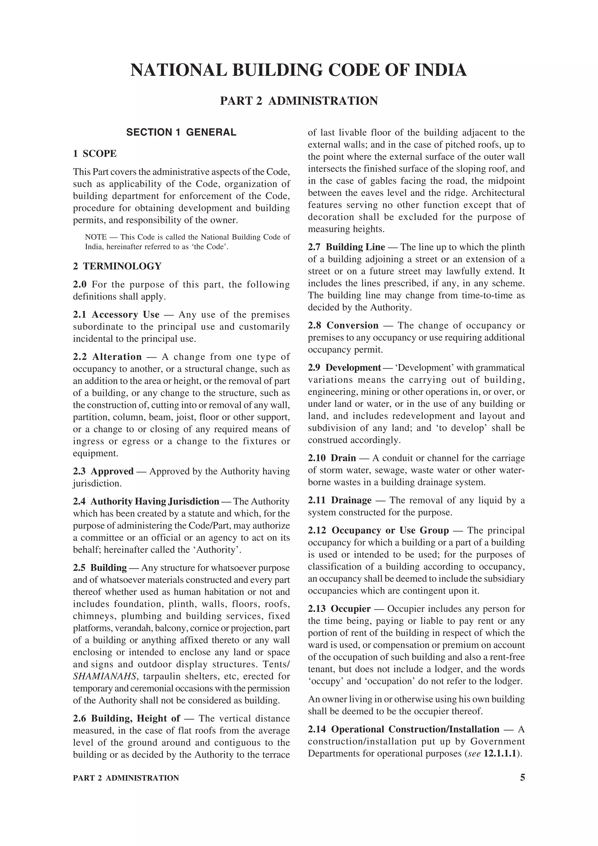
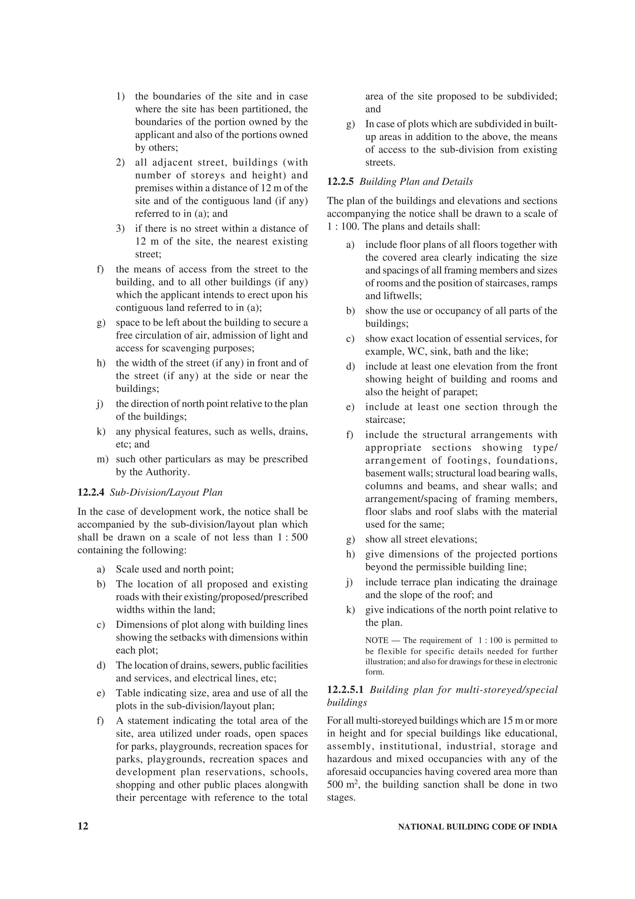
![PART 2 ADMINISTRATION 15
objections are raised when they are resubmitted after
compliance of earlier objections.
12.10.4 Once the plan has been scrutinized and
objections have been pointed out, the owner giving
notice shall modify the plan to comply with the
objections raised and re-submit it. The Authority shall
scrutinize the re-submitted plan and if there be further
objections, the plan shall be rejected.
13 RESPONSIBILITIES AND DUTIES OF THE
OWNER
13.1 Neither the granting of the permit nor the approval
of the drawings and specifications, nor inspections
made by the Authority during erection of the building
shall in any way relieve the owner of such building
from full responsibility for carrying out the work in
accordance with the requirements of the Code (see 9).
13.2 Every owner shall:
a) permit the Authority to enter the building or
premises for which the permit has been
granted at any reasonable time for the purpose
of enforcing the Code;
b) submit a document of ownership of the site;
c) obtain, where applicable, from the Authority,
permits relating to building, zoning, grades,
sewers, water mains, plumbing, signs,
blasting, street occupancy, electricity,
highways, and all other permits required in
connection with the proposed work;
d) give notice to the Authority of the intention
to start work on the building site (see
Annex F);
e) give written notice to the Authority intimating
completion of work up to plinth level;
f) submit the certificate for execution of work
as per structural safety requirements (see
Annex G); and give written notice to the
Authority regarding completion of work
described in the permit (see Annex H);
g) give written notice to the Authority in case of
termination of services of a professional
engaged by him; and
h) obtain an occupancy permit (see Annex J)
from the Authority prior to any:
1) occupancy of the building or part thereof
after construction or alteration of that
building or part, or
2) change in the class of occupancy of any
building or part thereof.
13.2.1 Temporary Occupancy
Upon the request of the holder of the permit, the
Authority may issue a temporary certificate of
occupancy for a building or part thereof, before the
entire work covered by permit shall have been
completed, provided such portion or portions may be
occupied safely prior to full completion of building
without endangering life or public welfare.
13.3 Documents at Site
13.3.1 Where tests of any materials are made to ensure
conformity with the requirements of the Code, records
of the test data shall be kept available for inspection
during the construction of the building and for such a
period thereafter as required by the Authority.
13.3.2 The person to whom a permit is issued shall
during construction keep pasted in a conspicuous place
on the property in respect of which the permit was
issued:
a) a copy of the building permit; and
b) a copy of the approved drawings and
specifications referred in 12.
14 INSPECTION, OCCUPANCY PERMIT AND
POST-OCCUPANCY INSPECTION
14.1 Generally all construction or work for which a
permit is required shall be subject to inspection by the
Authority and certain types of construction involving
unusual hazards or requiring constant inspection shall
have continuous inspection by special inspectors
appointed by the Authority.
14.2 Inspection, where required, shall be made within
7 days following the receipt of notification, after
which period the owner will be free to continue the
construction according to the sanctioned plan. At the
first inspection, the Authority shall determine to the
best of its ability that the building has been located
in accordance with the approved site plans. The final
inspection of the completion of the work shall be
made within 21 days following the receipt of
notification [see 13.2(f)] for the grant of occupancy
certificate.
14.2.1 The owner/concerned registered architect/
engineer/structural engineer/town planner will serve
a notice/completion certificate to the Authority that
the building has been completed in all respects as per
the approved plans. The deviations shall also be
brought to the notice of the Authority (with relevant
documents). The team of building officials or its duly
authorized representative shall then visit the site and
occupancy certificate shall be given in one instance.
14.2.2 The occupancy certificate should clearly state
the use/type of occupancy of the building. However,
the applicant can apply for change of use/occupancy
permitted within the purview of the Master Plan/Zonal
Plan/Building Byelaws, where so required.](https://image.slidesharecdn.com/is-200203030013/75/NATIONAL-BUILDING-CODE-SP7-42-2048.jpg)
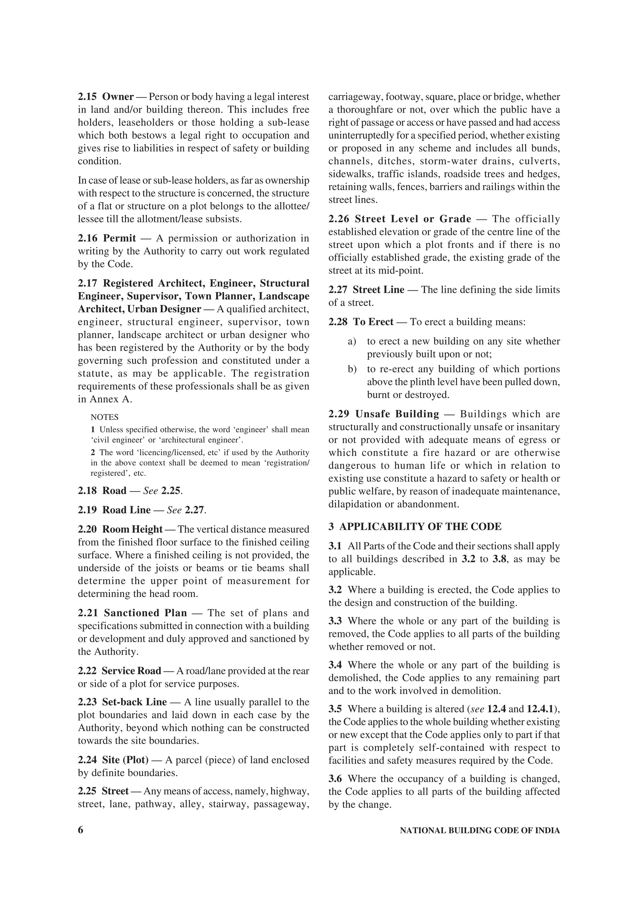
![22 NATIONAL BUILDING CODE OF INDIA
ANNEX E
(Clause 12.10)
FORM FOR SANCTION OR REFUSAL OF DEVELOPMENT/BUILDING PERMIT
To
...............................................
...............................................
...............................................
Sir,
With reference to your application ........................................dated ........................................for grant of permit
for the development, erection, re-erection or material alteration in the building No. ........................................
or to....................................................on/in Plot No....................................................................in Colony/
Street............................................MOHALLA/BAZAR/Road...........................................City...............................
I have to inform you that the sanction has been granted/refused by the Authority on the following grounds:
1.
2.
3.
4.
5.
6.
Office Stamp ............................................... Signature of the Authority ........................................
Office (Communication) No. ...................... Name, Designation and Address
of the Authority.......................................................
Date: ............................ .......................................................
.......................................................
ANNEX F
[Clause 13.2 (d)]
FORM FOR NOTICE FOR COMMENCEMENT
I hereby certify that the development, erection, re-erection or material alteration in/of building No. ...........................
or the..............................on/in Plot No....................................in Colony/Street.....................................MOHALLA/
BAZAR/Road....................................City ....................................will be commenced on as per your permission,
vide No.....................................dated..............................under the supervision of ....................................Registered
Architect/Engineer/Structural Engineer/Supervisor/Town Planner/Landscape Architect/Urban Designer1)
,
Registration No...............................................................and in accordance with the plans sanctioned, vide
No.....................................dated............................
Signature of Owner ....................................................
Name of Owner ..........................................................
(in block letters)
Address of Owner.......................................................
.......................................................
Date: ............................ .......................................................
1)
Strike out whichever is not applicable.](https://image.slidesharecdn.com/is-200203030013/75/NATIONAL-BUILDING-CODE-SP7-49-2048.jpg)
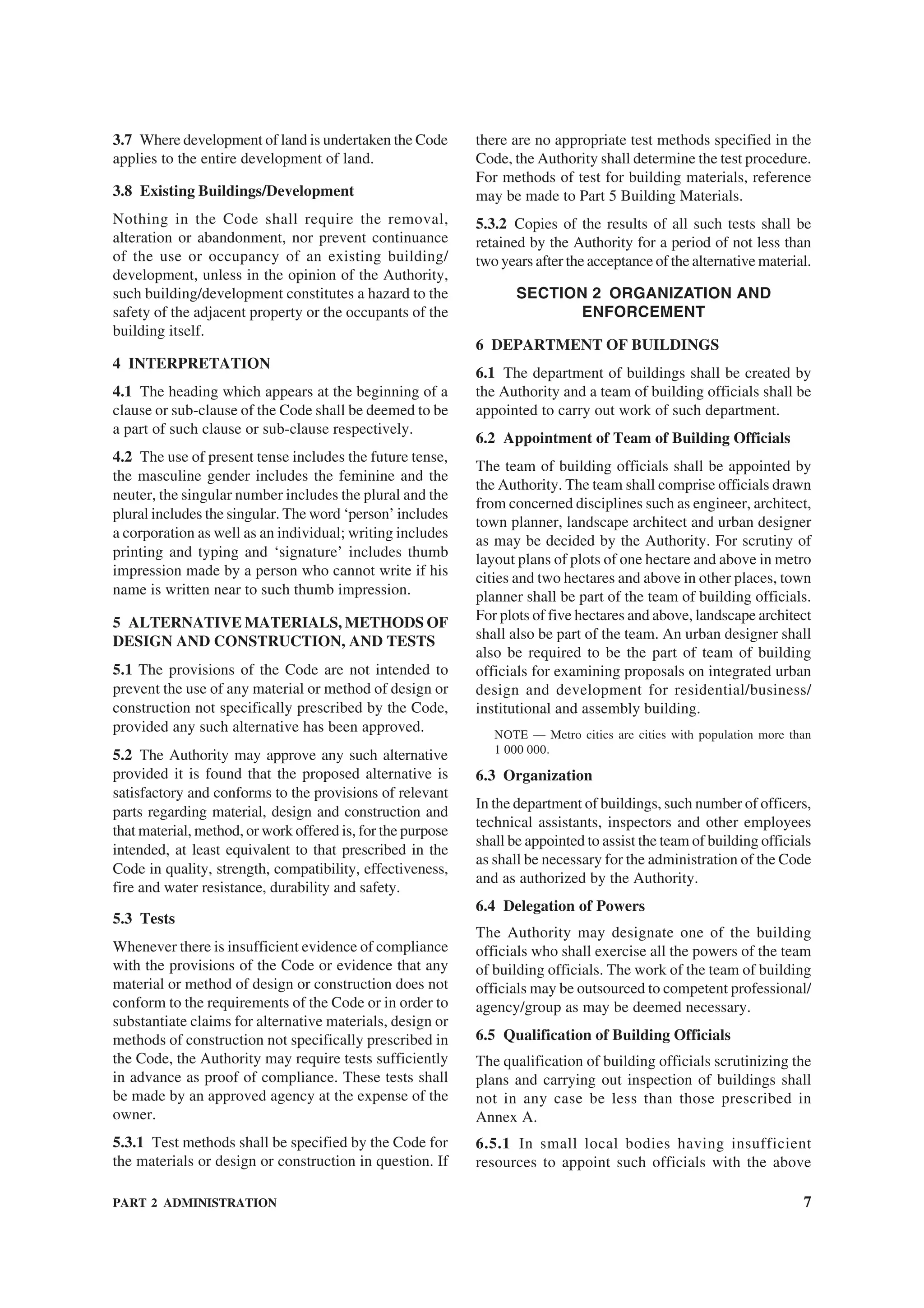
![PART 2 ADMINISTRATION 23
ANNEX G
[Clause 13.2(f)]
FORM FOR CERTIFICATE FOR EXECUTION OF WORK AS PER
STRUCTURAL SAFETY REQUIREMENTS
With respect to the building work of erection, re-erection or for making alteration in the building No..........................
or to ................................on/in Plot No.......................................Colony/Street ...................................MOHALLA/
BAZAR/Road ................................City................................, we certify:
a) that the building has been constructed according to the sanctioned plan and structural design (one set of
drawings as executed enclosed), which incorporates the provisions of structural safety as specified in
Part 6 ‘Structural Design’ of the National Building Code of India and other relevant Codes; and
b) that the construction has been done under our supervision and guidance and adheres to the drawings and
specifications submitted and records of supervision have been maintained.
Any subsequent changes from the completion drawings shall be the responsibility of the owner.
Signature of owner Signature of the
with date Registered Engineer/
Structural Engineer with
date and registration No.
Name: ........................................... ..........................................
Address: ........................................... ..........................................
ANNEX H
[Clause 13.2 (f)]
FORM FOR COMPLETION CERTIFICATE
I hereby certify that the development, erection, re-erection or material alteration in/of building No...........................
or the ........................... on/in Plot No............................ in Colony/Street ........................... MOHALLA/BAZAR/
Road...........................City........................... has been supervised by me and has been completed on ...........................
........................... according to the plans sanctioned, vide No. ........................... dated ...................... The work
has been completed to my best satisfaction, the workmanship and all the materials (type and grade) have been
used strictly in accordance with general and detailed specifications. No provisions of the Code, no requisitions
made, conditions prescribed or orders issued thereunder have been transgressed in the course of the work. The
land is fit for construction for which it has been developed or re-developed or the building is fit for use for which
it has been erected, re-erected or altered, constructed and enlarged.
I hereby also enclose the plan of the building completed in all aspects.
Signature of Architect/Engineer/Structural Engineer/Supervisor/Town Planner/Landscape Architect/Urban
Designer1)
.....................................................................
Name of Architect/Engineer/Structural Engineer/Supervisor/Town Planner/Landscape Architect/Urban
Designer1)
.....................................................................
(in block letters)
Registration No. of Architect/Engineer/Structural Engineer/Supervisor/Town Planner/Landscape Architect/Urban
Designer1)
.....................................................................
Address of Architect/Engineer/Structural Engineer/Supervisor/Town Planner/Landscape Architect/Urban
Designer1)
.....................................................................
Date: ............................. Signature of the Owner
1)
Strike out whichever is not applicable.](https://image.slidesharecdn.com/is-200203030013/75/NATIONAL-BUILDING-CODE-SP7-50-2048.jpg)
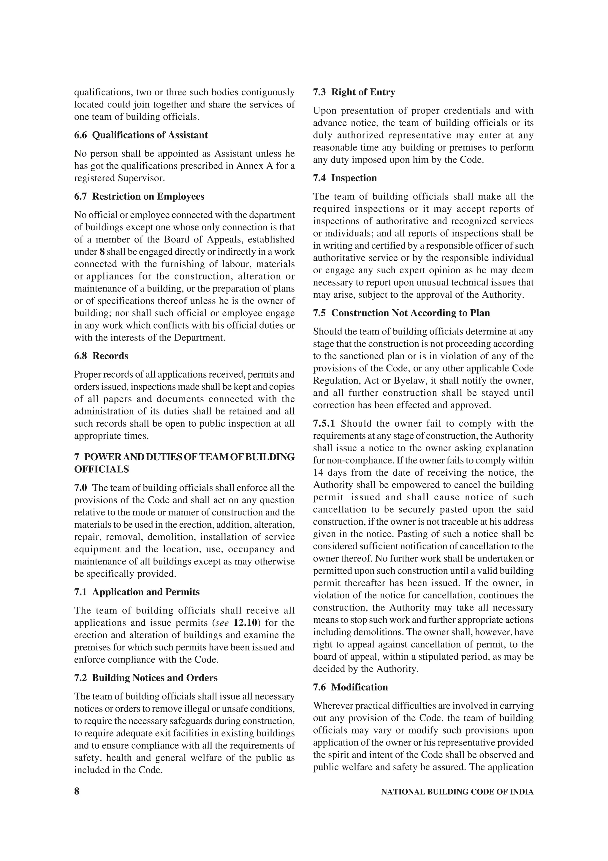
![24 NATIONAL BUILDING CODE OF INDIA
ANNEX J
[Clause 13.2(h)]
FORM FOR OCCUPANCY PERMIT
The work of erection, re-erection or alteration in/of building No.............................or the...............................on/
in Plot No.............................in Colony/Street.......................................MOHALLA/BAZAR/Road.................................
City.............................completed under the supervision of........................................Architect/Engineer/Structural
Engineer/Supervisor, Registration No.............................has been inspected by me. The building can be permitted/
not permitted for occupation for .............................occupancy subjected to the following:
1.
2.
3.
One set of completion plans duly certified is returned herewith.
Signature of the Authority ...................................
Office Stamp
Date: .........................](https://image.slidesharecdn.com/is-200203030013/75/NATIONAL-BUILDING-CODE-SP7-51-2048.jpg)
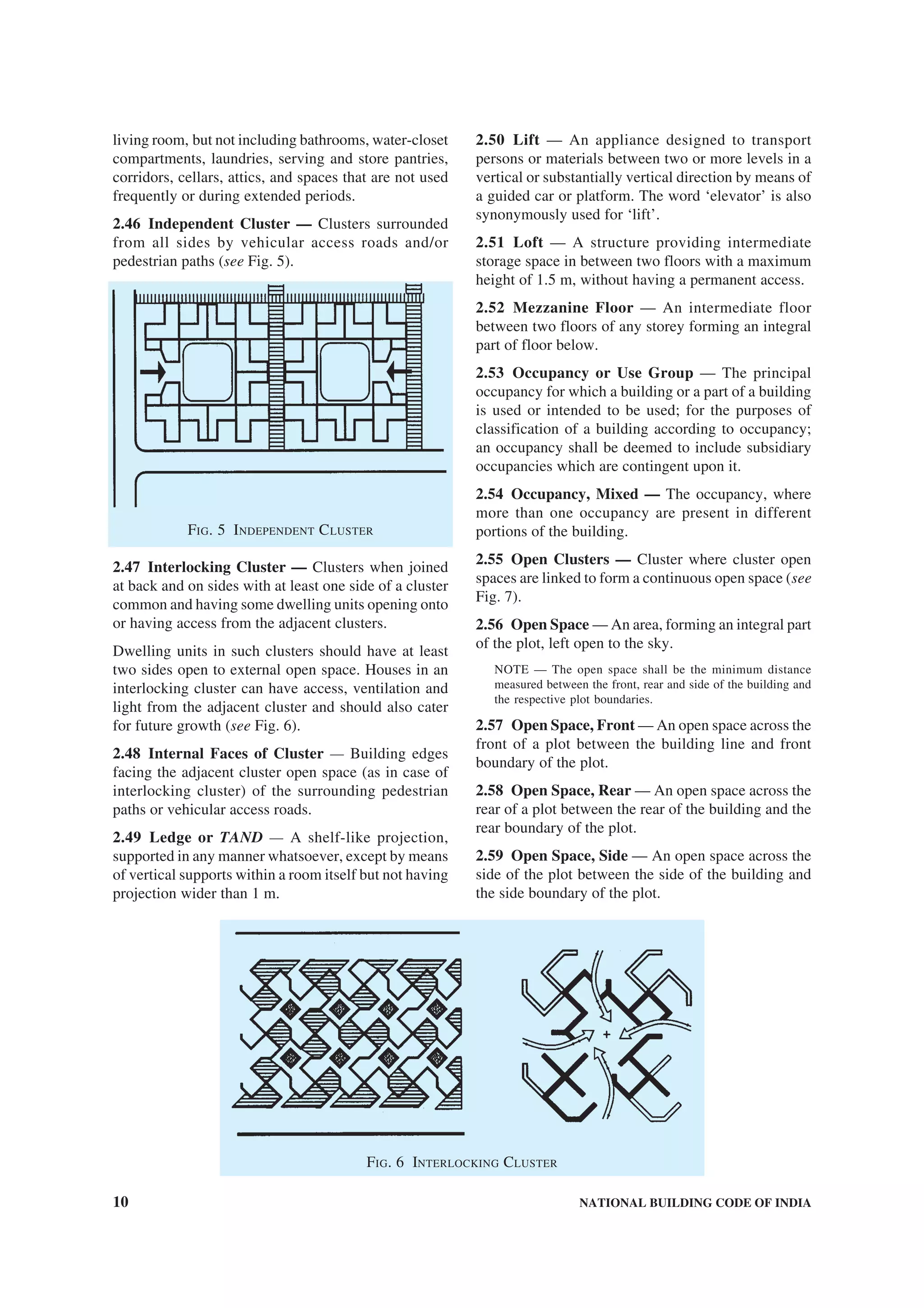
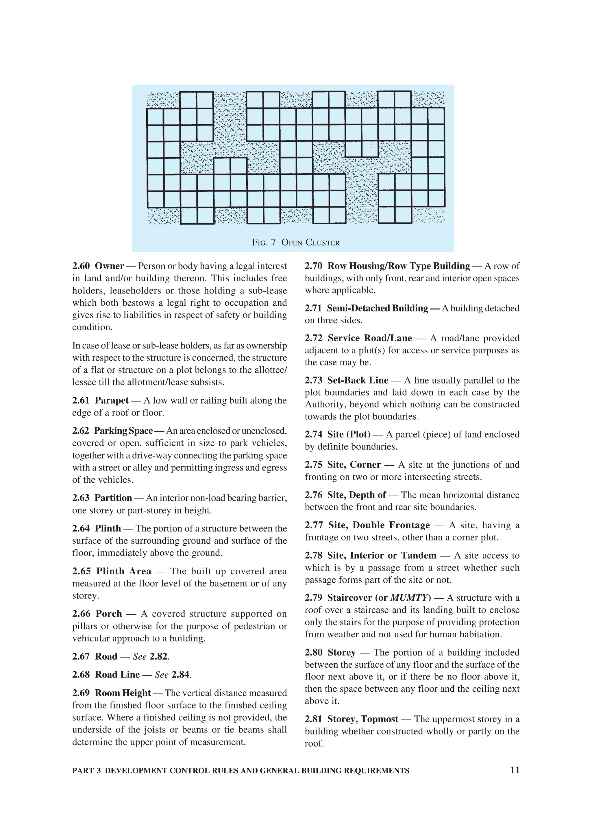
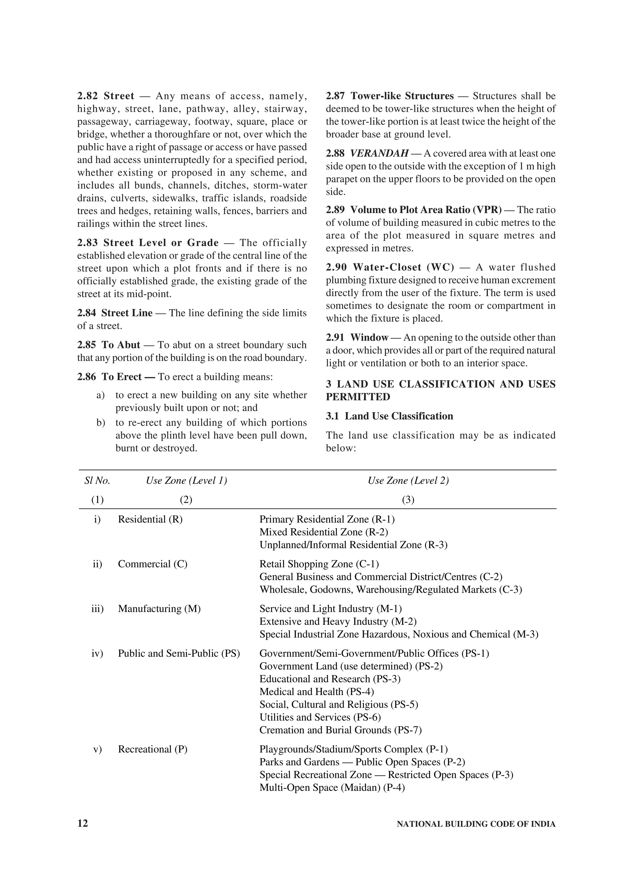

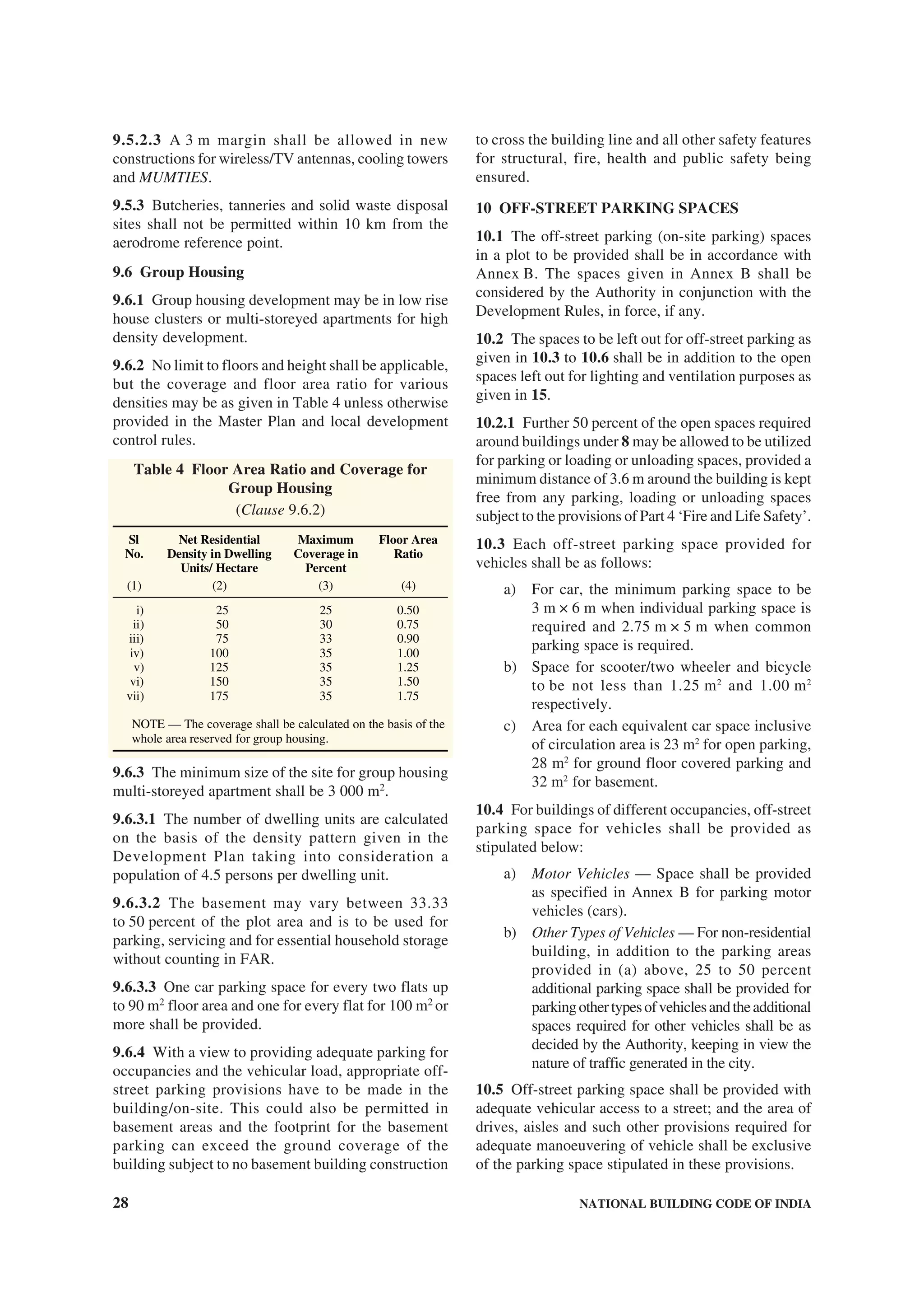
![PART 3 DEVELOPMENT CONTROL RULES AND GENERAL BUILDING REQUIREMENTS 25
c) Outer courtyard — The minimum width of
the outer courtyard (as distinguished from its
depth) shall be not less than 2.4 m. If the width
of the outer courtyard is less than 2.4 m, it
shall be treated as a notch and the provisions
of outer courtyard shall not apply. However,
if the depth of the outer courtyard is more than
the width, the provisions of 8.1.2 shall apply
for the open spaces to be left between the
wings.
8.2.6 Joint Open Air Space
Every such interior or exterior open air space, unless
the latter is a street, shall be maintained for the benefit
of such building exclusively and shall be entirely within
the owner’s own premises.
8.2.6.1 If such interior or exterior open air space is
intended to be used for the benefit of more than one
building belonging to the same owner, the width of
such open air space shall be the one specified for the
tallest building as specified in 8.2.3 abutting on such
open air space.
8.2.6.2 If such interior or exterior open air space is
jointly owned by more than one person, its width shall
also be as specified in 8.2, provided every such person
agrees in writing to allow his portion of such joint open
air space to be used for the benefit of every building
abutting on such joint open air space and provided he
sends such written consent to the Authority for record.
Such common open air space shall thenceforth be
treated as a permanently open air space required for
the purposes of the Code. No boundary wall between
such joint open air space shall be erected or raised to a
height of more than 2.0 m.
8.3 Other Occupancies
8.3.1 Open spaces for other occupancies shall be as
below:
a) Educational buildings — Except for nursery
schools, the open spaces around the building
shall be not less than 6 m.
b) Institutional buildings — The open spaces
around the building shall be not less than 6 m.
c) Assembly buildings — The open space at front
shall be not less than 12 m and the other open
spaces around the building shall be not less
than 6 m.
NOTE — However, if assembly buildings are permitted
in purely residential zones, the open spaces around the
building shall be not less than 12 m.
d) Business, mercantile and storage buildings —
The open spaces around the building shall be
not less than 4.5 m. Where these occur in a
purely residential zone or in a residential with
shops line zone the open spaces may be
relaxed.
e) Industrial buildings — The open spaces
around the building shall be not less than
4.5 m for heights up to 16 m, with an increase
of the open spaces of 0.25 m for every
increase of 1 m or fraction thereof in height
above 16 m.
NOTE — Special rules for narrow industrial plots in
the city, namely plots less than 15 m in width, and with
appropriate set-backs from certain streets and highways,
shall be applicable.
f) Hazardous occupancies — The open spaces
around the building shall be as specified for
industrial buildings [see 8.3.1 (e)].
8.4 Exemption to Open Spaces
8.4.1 Projections into Open Spaces
Every open space provided either interior or exterior
shall be kept free from any erection thereon and shall
be open to the sky, except as below:
a) Cornice, roof or weather shade not more than
0.75 m wide;
b) Sunshades over windows/ventilators or other
openings not more than 0.75 m wide;
c) Canopy not to be used as a sit out with
clearance of 1.5 m between the plot boundary
and the canopy;
d) Projected balcony at higher floors of width
not more than 1.2 m; and
e) Projecting rooms/balconies [see (d)] at
alternate floors such that rooms of the lower
two floors get light and air and the projection
being not more than the height of the storey
immediately below.
However, these projections into open spaces shall not
reduce the minimum required open spaces.
8.4.1.1 Accessory building
The following accessory buildings may be permitted
in the open spaces:
a) In an existing building, sanitary block of
2.4 m in height subject to a maximum of 4 m2
in the rear open space at a distance of 1.5 m
from the rear boundary may be permitted,
where facilities are not adequate.
b) Parking lock up garages not exceeding 2.4 m
in height shall be permitted in the side or
rear open spaces at a distance of 7.5 m from
any road line or the front boundary of the plot;
and
c) Suction tank and pump room each up to
2.5 m2
in area.](https://image.slidesharecdn.com/is-200203030013/75/NATIONAL-BUILDING-CODE-SP7-75-2048.jpg)
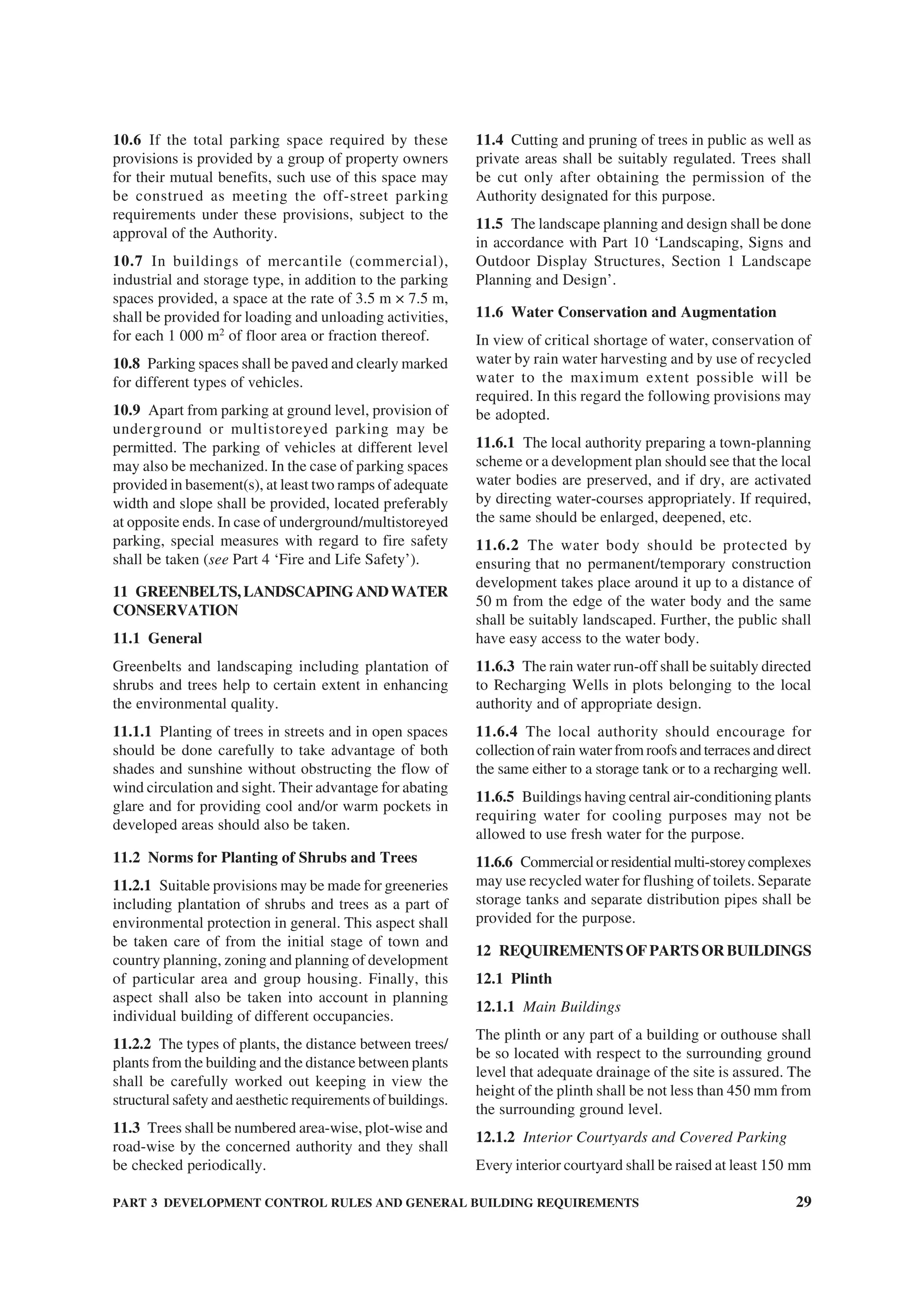
![PART 3 DEVELOPMENT CONTROL RULES AND GENERAL BUILDING REQUIREMENTS 33
12.15 Septic Tanks
Where a septic tank is used for sewage disposal, the
location, design and construction of the septic tank shall
conform to requirements of 12.15.1 and 12.15.2 [see
also Part 9 ‘Plumbing Services, Section 1 Water
Supply, Drainage and Sanitation (Including Solid
Waste Management)’].
12.15.1 Location of the Septic Tanks and Subsurface
Absorption Systems
A sub-soil dispersion system shall not be closer than
18 m from any source of drinking water, such as well,
to mitigate the possibility of bacterial pollution of water
supply. It shall also be as far removed from the nearest
habitable building as economically feasible but not
closer than 6 m, to avoid damage to the structures.
12.15.2 Requirements
a) Dimensions of septic tanks — Septic tanks
shall have a minimum width of 750 mm, a
minimum depth of 1 m below the water level
and a minimum liquid capacity of 1 m3
. The
length of tanks shall be 2 to 4 times the width;
b) Septic tanks may be constructed of brickwork,
stone masonry, concrete or other suitable
materials as approved by the Authority;
c) Under no circumstances shall effluent from a
septic tank be allowed into an open channel
drain or body of water without adequate
treatment;
d) The minimum nominal diameter of the pipe
shall be 100 mm. Further, at junctions of pipes
in manholes, direction of flow from a branch
connection shall not make an angle exceeding
45° with the direction of flow in the main pipe;
e) The gradients of land drains, under-drainage
as well as the bottom of dispersion trenches
and soakways shall be between 1:300 and
1:400;
f) Every septic tank shall be provided with
ventilating pipe of at least 50 mm diameter.
The top of the pipe shall be provided with a
suitable cage of mosquito-proof wire mesh.
The ventilating pipe shall extend to a height
which would cause no smell nuisance to any
building in the area. Generally, the ventilating
pipe may extend to a height of about 2 m,
when the septic tank is at least 15 m away
from the nearest building and to a height of
2 m above the top of the building when it is
located closer than 15 m;
g) When the disposal of septic tank effluent is
to a seepage pit, the seepage pit may be of
any suitable shape with the least cross-
sectional dimension of 0.90 m and not less
than 1.00 m in depth below the invert level of
the inlet pipe. The pit may be lined with stone,
brick or concrete blocks with dry open joints
which should be backed with at least 75 mm
of clean coarse aggregate. The lining above
the inlet level should be finished with mortar.
In the case of pits of large dimensions, the
top portion may be narrowed to reduce the
size of the RCC cover slabs. Where no lining
is used, specially near trees, the entire pit
should be filled with loose stones. A masonry
ring may be constructed at the top of the pit
to prevent damage by flooding of the pit by
surface runoff. The inlet pipe may be taken
down a depth of 0.90 m from the top as an
anti-mosquito measure; and
h) When the disposal of the septic tank effluent
is to a dispersion trench, the dispersion trench
shall be 0.50 m to 1.00 m deep and 0.30 m to
1.00 m wide excavated to a slight gradient
and shall be provided with 150 mm to 250 mm
of washed gravel or crushed stones. Open
jointed pipes placed inside the trench shall
be made of unglazed earthenware clay or
concrete and shall have a minimum internal
diameter of 75 mm to 100 mm. Each
dispersion trench shall not be longer than
30 m and trenches shall not be placed closer
than 1.8 m.
12.16 Office-cum-Letter Box Room
In the case of multi-storeyed multi-family dwelling
apartments constructed by existing and proposed
Cooperative Housing Societies or Apartment Owners
Associations, limited companies and proposed
societies, an office-cum-letter box room of dimension
3.6 m × 3 m shall be provided on the ground floor. In
case the number of flats is more than 20, the maximum
size of the office-cum-letter box room shall be 20 m2
.
12.16.1 Business Buildings
Provision shall be made for letter boxes on the entrance
floor as per the requirements of the postal department.
12.17 Meter Rooms
For all buildings above 15 m in height and in special
occupancies, like educational, assembly, institutional,
industrial, storage, hazardous and mixed occupancies
with any of the aforesaid occupancies having area more
than 500 m2
on each floor, provision shall be made for
an independent and ventilated meter (service) room,
as per requirements of electric (service) supply
undertakings on the ground floor with direct access
from outside for the purpose of termination of electric](https://image.slidesharecdn.com/is-200203030013/75/NATIONAL-BUILDING-CODE-SP7-83-2048.jpg)
![34 NATIONAL BUILDING CODE OF INDIA
supply from the licensee’s service and alternative
supply cables. The door/doors provided for the service
room shall have fire resistance of not less than two
hours.
12.18 Staircase/Exit Requirements
12.18.1 The minimum clear width, minimum tread
width and maximum riser of staircases for buildings
shall be as given in 12.18.1.1 to 12.18.1.3 (see also
Part 4 ‘Fire and Life Safety’).
12.18.1.1 Minimum width — The minimum width of
staircase shall be as follows:
a) Residential buildings (dwellings) 1.0 m
NOTE — For row housing with 2 storeys,
the minimum width shall be 0.75 m.
b) Residential hotel buildings 1.5 m
c) Assembly buildings like 2.0 m
auditoria, theatres and cinemas
d) Educational building 1.5 m
e) Institutional buildings 2.0 m
f) All other buildings 1.5 m
12.18.1.2 Minimum tread
The minimum width of tread without nosing shall be
250 mm for residential buildings. The minimum width
of tread for other buildings shall be 300 mm.
12.18.1.3 Maximum riser
The maximum height of riser shall be 190 mm for
residential buildings and 150 mm for other buildings
and these shall be limited to 12 per flight.
12.18.2 The minimum head-room in a passage under
the landing of a staircase shall be 2.2 m. The minimum
clear head-room in any staircase shall be 2.2 m.
12.18.3 Exit Requirements
All aspects of exit requirements for corridors, doors,
stair cases, ramps, etc in respect of widths, travel
distance shall be as per Part 4 ‘Fire and Life Safety’.
12.19 Roofs
12.19.1 The roof of a building shall be so designed
and constructed as to effectively drain water by means
of sufficient rain-water pipes of adequate size,
wherever required, so arranged, jointed and fixed as
to ensure that the rain-water is carried away from the
building without causing dampness in any part of the
walls, roof or foundations of the building or an adjacent
building.
12.19.2 The Authority may require rain-water pipes
to be connected to a drain or sewer to a covered channel
formed beneath the public footpath to connect the rain-
water pipe to the road gutter or in any other approved
manner.
12.19.3 Rain-water pipes shall be affixed to the
outside of the external walls of the building or in
recesses or chases cut or formed in such external walls
or in such other manner as may be approved by the
Authority.
12.19.4 It is desirable to conserve rain water using
suitable rain water harvesting techniques including by
roof water collection. In this context, reference may
be made to Part 9 ‘Plumbing Services, Section 1 Water
Supply, Drainage and Sanitation (Including Solid
Waste Management)’.
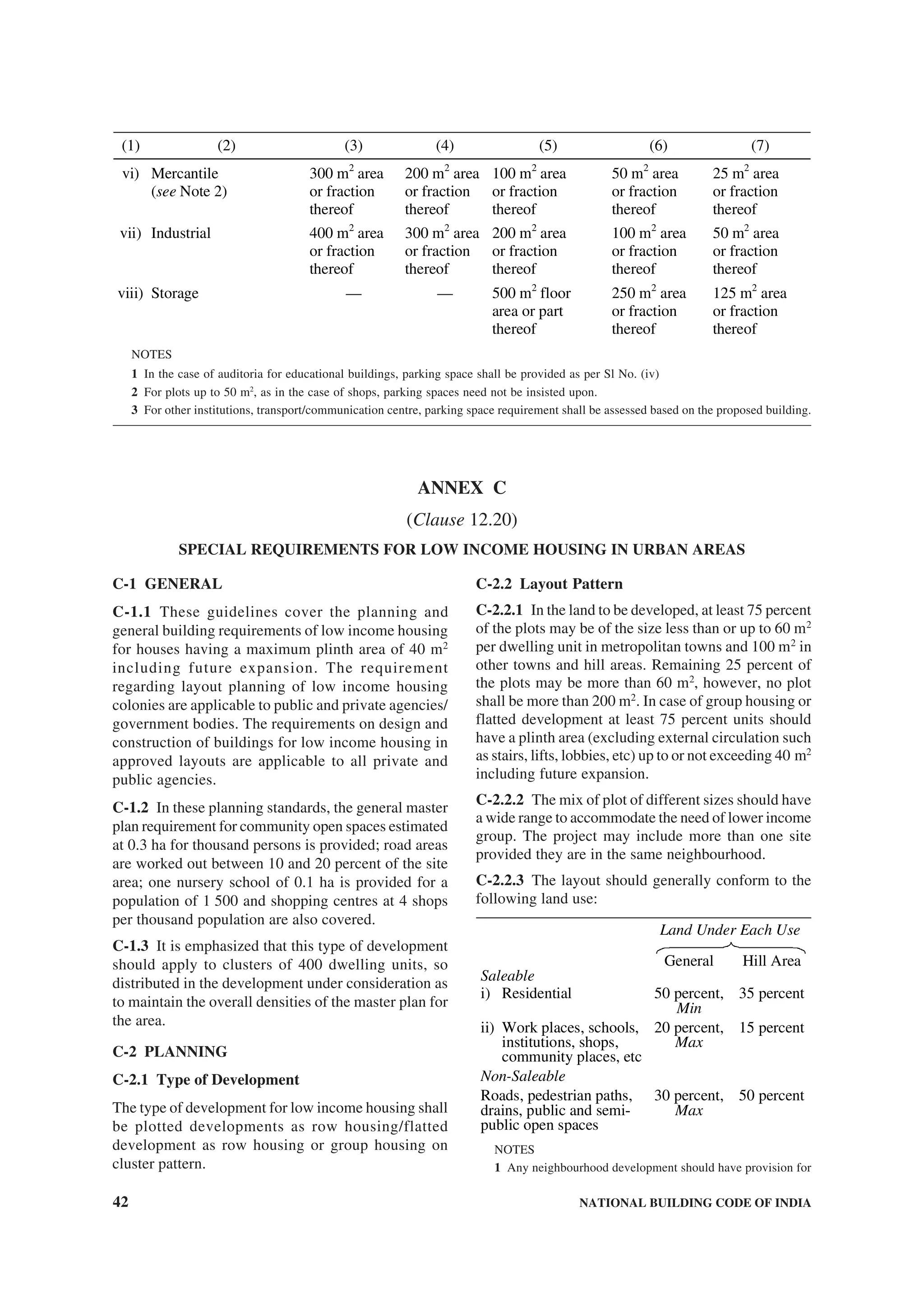
12.20 Special Requirements of Low Income
Housing
Special requirements of low income housing shall be
as given in Annex C. For detailed information in this
regard, reference may be made to the accepted
standards [3(1)].
12.21 SpecialRequirementsforPhysicallyChallenged
Special requirements for planning of buildings and
facilities keeping in view the needs of the physically
challenged, applicable particularly to public buildings
meant for their use, are given in Annex D.
12.22 Special Requirements for Cluster Planning
for Housing
Special requirements for cluster planning for housing
shall be as given in Annex E.
12.23 Special Requirements for Low Income
Habitat Planning in Rural Areas
Special requirements for low income habitat planning
in rural areas shall be as given in Annex F.
12.24 Special Requirements for Development
Planning in Hilly Areas
Special requirements for development planning in hilly
areas is given in Annex G.
13 FIRE AND LIFE SAFETY
For requirements regarding fire and life safety for
different occupancies, reference shall be made to Part 4
‘Fire and Life Safety’.
14 DESIGN AND CONSTRUCTION
For requirements regarding structural design, reference
shall be made to Part 6 ‘Structural Design’ and for
construction (including safety) reference shall be made
to Part 7 ‘Constructional Practices and Safety’.
15 LIGHTING AND VENTILATION
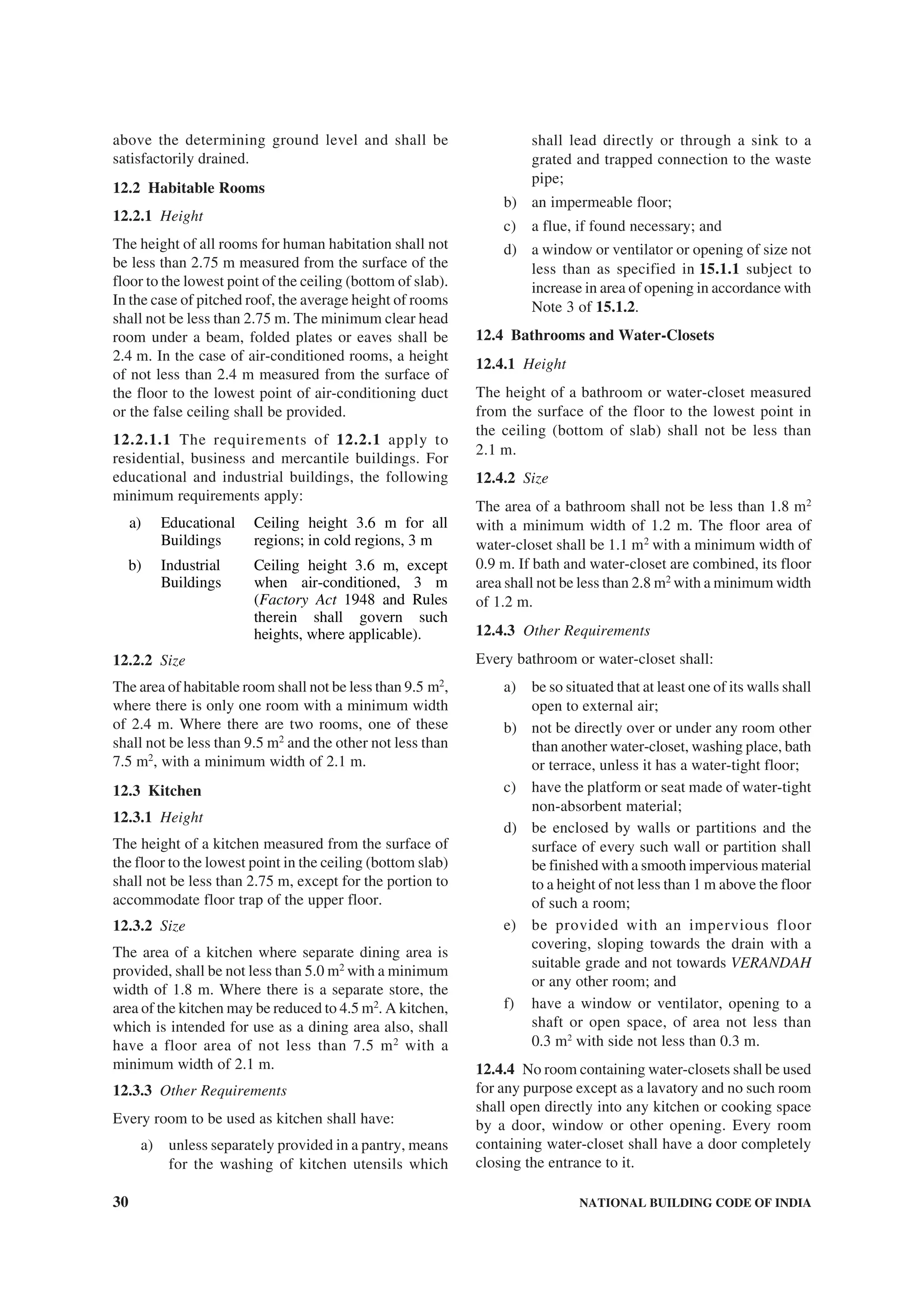
15.1 For requirements regarding lighting and](https://image.slidesharecdn.com/is-200203030013/75/NATIONAL-BUILDING-CODE-SP7-84-2048.jpg)
![PART 3 DEVELOPMENT CONTROL RULES AND GENERAL BUILDING REQUIREMENTS 35
ventilation for different uses and occupancies,
reference shall be made to Part 8 ‘Building Services,
Section 1 Lighting and Ventilation’.
15.1.1 Lighting and Ventilation of Rooms
Rooms shall have, for the admission of light and air,
one or more openings, such as windows and ventilators,
opening directly to the external air or into an open
VERANDAH.
15.1.2 Notwithstanding the area of openings obtained
through 15.1, the minimum aggregate area (see Notes
1 to 3) of such openings, excluding doors inclusive of
frames, shall be not less than:
a) one-tenth of the floor area for dry hot climate;
b) one-sixth of the floor area for wet hot
climate;
c) one-eighth of the floor area for intermediate
climate; and
d) one-twelfth of the floor area for cold climate.
NOTES
1 If a window is partly fixed, the openable area shall
be counted.
2 No portion of a room shall be assumed to be lighted,
if it is more than 7.5 m away from the opening assumed
for lighting that portion.
3 The area of openings as given in (a) to (d) above
shall be increased by 25 percent in the case of a kitchen
[see 12.3.3(d)].
16 ELECTRICALANDALLIEDINSTALLATIONS
(INCLUDING LIGHTNING PROTECTION OF
BUILDINGS)
For requirements regarding electrical installations in
buildings including lightning protection of buildings,
reference shall be made to Part 8 ‘Building Services,
Section 2 Electrical and Allied Installations’.
17 AIR CONDITIONING, HEATING AND
MECHANICAL VENTILATION
For requirements regarding design, construction and
installation of air conditioning, heating and mechanical
ventilation systems, reference shall be made to Part 8
‘Building Services, Section 3 Air Conditioning,
Heating and Mechanical Ventilation’.
18 ACOUSTICS, SOUND INSULATION AND
NOISE CONTROL
For requirements regarding the desired noise levels and
sound insulation in different occupancies, reference
shall be made to Part 8 ‘Building Services, Section 4
Acoustics, Sound Insulation and Noise Control’.
19 HEAT INSULATION
For calculation of solar radiation on buildings and
recommended limits of thermal transmittance of roofs
and walls for different parts of the country and heat
transmission losses due to different constructions,
reference may be made to good practice [3(2)].
20 INSTALLATION OF LIFTS AND
ESCALATORS
Provision for lifts shall be made for buildings 15 m or
more in height. For requirements regarding planning,
designing and installation, etc of lifts and escalators,
reference shall be made to Part 8 ‘Building Services,
Section 5 Installation of Lifts and Escalators’.
21 PLUMBING SERVICES AND SOLID WASTE
MANAGEMENT
For requirements regarding water supply, drainage and
sanitation (including solid waste management) and gas
supply, reference shall be made to Part 9 ‘Plumbing
Services’.](https://image.slidesharecdn.com/is-200203030013/75/NATIONAL-BUILDING-CODE-SP7-85-2048.jpg)
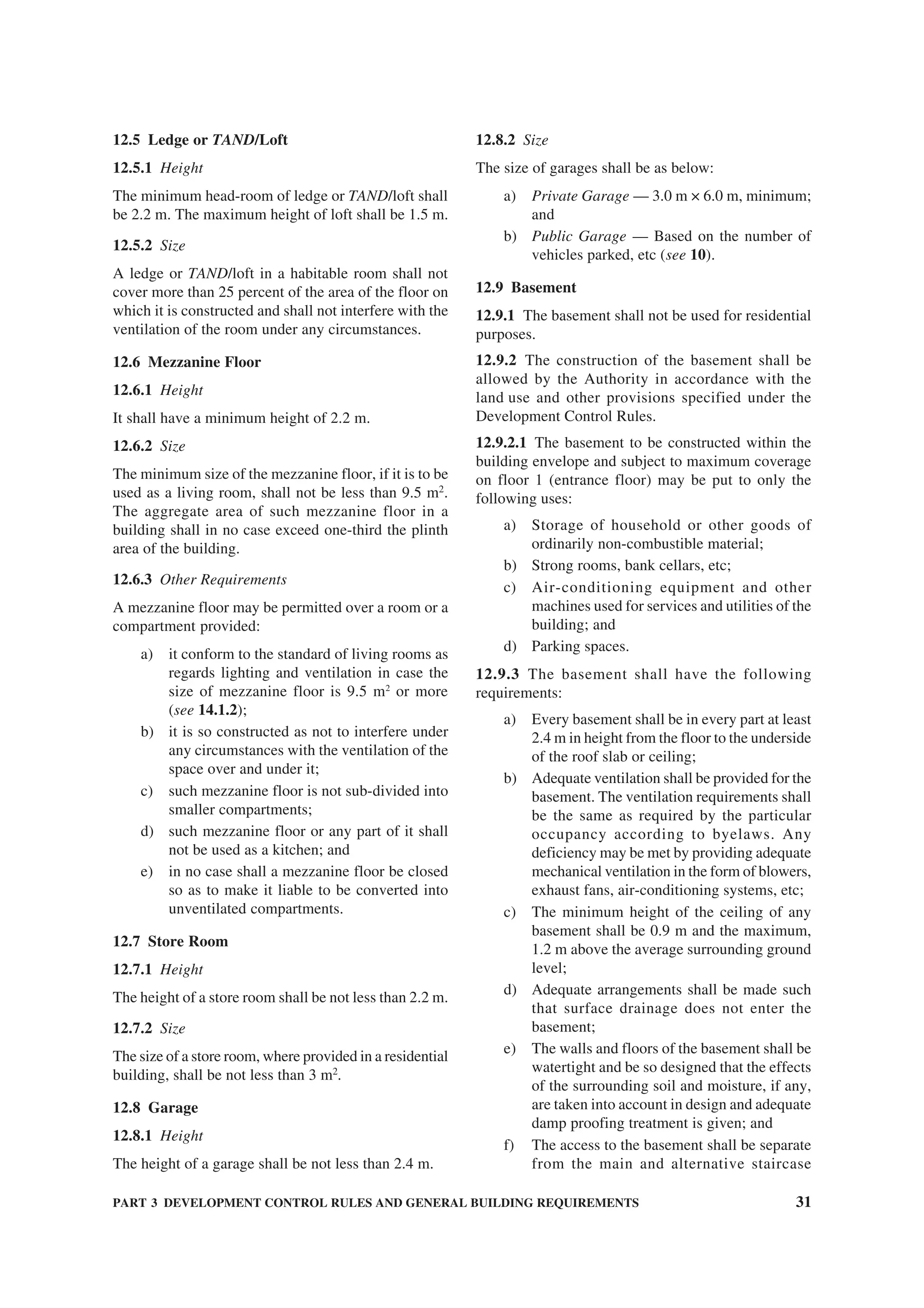
![44 NATIONAL BUILDING CODE OF INDIA
clear height below and above the mezzanine floor
should be 2.4 m and 2.1 m respectively.
As far as possible mezzanine floor should have direct
ventilation from the external face of the building.
Where this is not possible ventilation through main
room may be allowed provided total area of openings
in the main room is provided taking into consideration
area of mezzanine floor.
Such mezzanine floor may be accessible through the
main room by a ladder, whose minimum angle with
vertical plane should be 22½°. Height of the riser
should be less than 250 mm.
C-3.3.2 Water Closet/Bathroom
1) The size of independent water-closet shall be
0.90 m2
with minimum width of 0.9 m;
2) The size of independent bathroom shall be
1.20 m2
with a minimum width of 1.0 m; and
3) The size of combined bathroom and water-
closet shall be 1.80 m2
with minimum width
of 1.0 m.
C-3.3.3 Kitchen
The size of a cooking alcove serving as cooking space
shall not be less than 2.4 m2
with a minimum width of
1.2 m. The size of individual kitchen provided in a
two-roomed house shall not be less than 3.3 m2
with a
minimum width of 1.5 m.
C-3.3.4 Balcony
The minimum width of individual balcony, where
provided, shall be 0.9 m and shall not be more than
1.2 m and it shall not project beyond the plot line and
on roads or pathway.
C-3.4 Basement
No basement floor shall be allowed.
C-3.5 Minimum Height
The minimum height of rooms/spaces shall be as
follows:
a) Habitable room 2.6 m
b) Kitchen 2.6 m
c) Bath/water-closet 2.1 m
d) Corridor 2.1 m
C-3.5.1 In the case of sloping roofs, the average height
of roof for habitable rooms shall be 2.6 m and the
minimum height at eaves shall be 2.0 m.
C-3.6 Lighting and Ventilation
The openings through windows, ventilators and other
openings for lighting and ventilation shall be in
accordance with 15.1.2.
NOTE — The windows and other openings shall abut onto
open spaces either through areas left open within the plot or
the front, side and rear spaces provided in the layouts which
shall be deemed to be sufficient for light and ventilation
purposes. Wherever ventilation/lighting is provided by means
of JALI or grill of any material, total area of openings shall
calculated excluding solid portion of the JALI or grill.
C-3.7 Stairs
The following criteria shall be adopted for internal
individual staircase:
a) Minimum Width
1) 2 storeyed — straight 0.60 m
2) 2 storeyed — winding 0.75 m
3) 3 or more storeyed —
straight
0.75 m
4) 3 or more storeyed —
winding
0.90 m
b) Riser 200 mm, Max
c) Tread
1) 2 storeyed 225 mm, Min
(see Note)
2) 3 storeyed or more 250 mm, Min
d) Head Room — The minimum
clear head room shall be 2.1 m.
NOTE — This could be reduced to 200 mm as the clear tread
between perpends, with possibility of open riser as well as
nosing and inclined riser to have an effective tread of 225 mm.
C-3.8 Circulation Area
The circulation area on any floor including staircase,
shall not exceed 8 m2
/dwelling unit.
C-3.9 Water Seal Latrine
No building plan shall be approved and no building
shall be deemed to have been completed and fit for
human occupation unless provision is made for water
seal latrine. No dry latrine shall be allowed. Water seal
latrines can also be provide on the basis of community
toilets or shared toilets as per the recommendation
given in good practice [3(3)].
Where leaching pits are used, it should be constructed
within the premises of the households as it would be
economical as well as facilitate their cleaning. However,
where, due to space constraint, construction of pits
within the premises may not be possible, pits may be
constructed in places like lanes, streets and roads.
In case the pit is located under the road, street or foot
path, the inverted level of the pipe connecting the
latrine pan with the pit shall be at least 1.1 m below
ground level or below the bottom of the water main
existing within a distance of 3 m from the pits
whichever is more. Construction of such pits may be
in accordance with good practice [3(4)].](https://image.slidesharecdn.com/is-200203030013/75/NATIONAL-BUILDING-CODE-SP7-94-2048.jpg)
![56 NATIONAL BUILDING CODE OF INDIA
D-3.16 Hazards
Every effort shall be exercised to obviate hazards to
individuals with physical disabilities.
D-3.16.1 Access panels or manholes in floors, walks,
and walls may be extremely hazardous, particularly
when in use, and should be avoided.
D-3.16.2 When manholes or access panels are open
and in use, or when an open excavation exists on a
site, particularly when it is in proximity of normal
pedestrian traffic, barricades shall be placed on all open
sides, at least 8.5 m from the hazard, and warning
devices shall be installed in accordance with D-3.14.2.
D-3.16.3 Low-hanging door closers that remain within
the opening of a doorway, when the door is open or
that protrude hazardously into regular corridors or
traffic ways when the door is closed, shall be avoided.
D-3.16.4 Low-hanging signs, ceiling lights, and
similar objects or signs and fixtures that protrude into
regular corridors or traffic way shall be avoided. A
minimum height of 2.1 m measured from the floor is
recommended.
D-3.16.5 Ramps shall be adequately lighted.
D-3.16.6 Exit signs shall be in accordance with good
practices [3(5)].
D-3.16.7 Equipment and materials causing allergic
reactions should as far as possible be avoided in
dwellings and buildings.
D-4 DESIGNING FOR CHILDREN
The dimensions given in this Annex are for adults of
average stature. In designing buildings for use by
children, it may be necessary to alter some dimensions,
such as, height of handrails, in accordance with
accepted standards [3(6)].
D-5 For additional information regarding other
facilities and conveniences required in buildings meant
for use of physically challenged, reference may be
made to accepted standards [3(7)].
ANNEX E
(Clauses 12.22, C-2.3.1 and C-2.6)
SPECIAL REQUIREMENTS OF CLUSTER PLANNING FOR HOUSING
E-1 GENERAL
E-1.1 These guidelines cover planning and building
requirements of housing developed as clusters. These
requirements are applicable to all housing projects
taken up by public, private or co-operative agencies.
E-2 PLANNING
E-2.1 Plot Size
The minimum plot size permissible shall be 15 m2
with
100 percent ground coverage and an FSI of two.
Hundred percent ground coverage and FSI of 2 will
be applicable up to plot size of 25 m2
. For plot sizes
beyond 25 m2
, provision in accordance with good
practice [3(1)] shall be applicable.
E-2.2 Plot/Plinth Area for Slum Resettlement on
Same Site
In case of slum resettlement on the same site, minimum
area may be reduced to 12.5 m2
with potential for adding
another 12.5 m2
on first floor with an internal staircase.
E-2.3 Group Housing
Group housing may be permitted within cluster housing
concept. However, dwelling units with plinth areas up
to 20 m2
should have scope for adding a habitable
room. Group housing in a cluster should not be more
than 15 m in height.
E-2.4 Size of Cluster
In ground and one storeyed structures not more than
20 houses should be grouped in a cluster. Clusters with
more dwelling units may create problems relating to
identity, encroachment and maintenance.
E-2.5 Size of Cluster Open Space
Minimum dimensions of open spaces shall be not less
than 6 m or 3/4th of the height of buildings along the
cluster open space, whichever is higher. The area of
such cluster court shall not be less than 36 m2
. Group
housing around a cluster open space should not be
normally more than 15 m in height. Maximum cluster
courtyard width and breadth shall be 13 m.
E-2.6 Setbacks
No setbacks are needed from the edges of cluster as
pedestrian/vehicular access roads surrounding the
cluster.](https://image.slidesharecdn.com/is-200203030013/75/NATIONAL-BUILDING-CODE-SP7-106-2048.jpg)
![PART 3 DEVELOPMENT CONTROL RULES AND GENERAL BUILDING REQUIREMENTS 57
E-2.7 Right to Build in Sky
Pedestrian paths and vehicular access roads to clusters
separating two adjacent clusters may be bridged to
provide additional dwelling units. While bridging the
pedestrian path way minimum clearance should be one
storey height, length of such bridging should be not more
than two dwelling units. While bridging the vehicular
access roads minimum clearance should be 6 m.
E-2.8 Vehicular Access
A right of way of at least 6 m width should be provided
up to the entrance to the cluster to facilitate emergency
vehicle movement up to cluster.
E-2.9 Pedestrian Paths
Minimum width of pedestrian paths shall be 3 m.
E-2.10 Width of Access Between Two Clusters
Built area of dwelling unit within cluster shall have no
setbacks from the path or road, space. Hence, the height
of the building along the pathway or roads shall be not
less than 60 percent of the height of the adjacent
building subject to minimum of 3 m in case of pathway
and 6 m in case of vehicular access.
E-2.11 Density
Cluster planning methodologies result in higher
densities with low rise structures. With per dwelling
unit covered area of 15 m2
densities of 500 dwelling
units per hectare (net) shall be permissible. Densities
higher than this should not allowed.
E-2.12 Group Toilet
Cluster housing for economically weaker section
families can have group toilets at the rate of one water-
closet, one bath and a washing place for three families.
These shall not be community toilets, as keys to these
toilets shall be only with these three families, making
them solely responsible for the maintenance and
upkeep of these toilets.
E-3 OTHER REQUIREMENTS
E-3.1 Requirements of Building Design
With the exception of clauses mentioned above,
requirements of building will be governed by the
provision of this Code and good practice [3(1)].
E-3.2 Requirements of fire safety, structural design,
building services and plumbing services shall be as
specified in this Code.
F-1 GENERAL
F-1.1 These guidelines cover planning and general
building requirements for low-income houses having
a maximum built-up area of 40 m2
including future
expansion, built on notified (as notified by the State
Governments) rural areas. The provisions on layout
planning of low-income housing colonies in rural areas
are applicable to public and private agencies/
government bodies. The provisions of this Code on
design and construction of buildings for low income
housing in approved layouts are applicable to all private
and public agencies.
F-2 SETTLEMENT AND ENVIRONMENT
PLANNING
F-2.1 While planning for rural settlements the
following factors shall be taken into consideration:
a) Ecosystem and Biodiversity.
b) Topography with its direct effect on climate,
likelihood of natural disasters, natural
drainage, etc.
c) Identity of the place rooted in its culture and
heritage.
d) Nearness and connectivity with nearby urban
centres.
e) Occupation related requirements.
f) Water management.
g) Waste management.
h) Land tenure.
j) Site selected shall be conveniently
approachable and suitably developed and
shall not be subjected to water logging/
flooding.
k) Plot size : 80 m2
, Min
m) Density (Gross) : 60 plots per hectare,
Max
n) Minimum frontage : 6 m
ANNEX F
(Clause 12.23)
SPECIAL REQUIREMENTS FOR LOW INCOME HABITAT PLANNING
IN RURAL AREAS](https://image.slidesharecdn.com/is-200203030013/75/NATIONAL-BUILDING-CODE-SP7-107-2048.jpg)
![PART 3 DEVELOPMENT CONTROL RULES AND GENERAL BUILDING REQUIREMENTS 59
a) Habitable room 2.75 m
b) Kitchen 2.6 m
c) Bath/water-closet 2.2 m
d) Corridor 2.1 m
F-3.4.1 In the case of sloping roofs, the average height
of roof for habitable rooms shall be 2.75 m and the
minimum height at eaves shall be 2.10 m.
F-3.5 Lighting and Ventilation
The openings through windows, ventilators and other
openings for lighting and ventilation shall be as per in
accordance with 15.1.2.
NOTE — The windows and other openings shall abut onto
open spaces either through areas left open within the plot or
the front, side and rear spaces provided in the layouts which
shall be deemed to be sufficient for light and ventilation
purposes. Wherever ventilation/lighting is provided by means
of JALI or grill of any material, total area of openings shall
calculated excluding solid portion of the JALI or grill.
F-3.6 Stairs
The following criteria shall be adopted for internal
individual staircase:
a) Minimum width
1) 2 storeyed-straight 0.60 m
2) 2 storeyed-winding 0.75 m
3) 3 or more storeyed-straight 0.75 m
4) 3 or more storeyed-winding 0.90 m
b) Riser 200 mm, Max
c) Tread
1) 2 storeyed 225 mm, Min
2) 3 storeyed or more 250 mm, Min
NOTE — This could be reduced to 20 cm as the clear tread
between perpends, with possibility of open riser as well as
nosing and inclined riser to have an effective going of
22.5 cm.
F-3.7 Water Seal Latrine
No building plan shall be approved and no building
shall be deemed to have been completed and fit for
human occupation unless provision is made for water
seal latrine. No dry latrine shall be allowed. Water seal
latrines can also be provide on the basis of community
toilets or shared toilets as per the recommendation
given in [3(3)].
Where leaching pits are used, it should be constructed
within the premises of the households as it would be
economical as well as facilitate their cleaning. However,
where, due to space constraint, construction of pits
within the premises may not be possible, pits may be
constructed in places like lanes, streets and roads.
In case the pit is located under the road, street or foot
path, the inverted level of the pipe connecting the
latrine pan with the pit shall be at least 1.1 m below
ground level or below the bottom of the water main
existing within a distance of 3 m from the pits
whichever is more. Construction of such pits may be
in accordance with [3(4)].
The water seal latrine should be properly maintained
and kept in sanitary condition by the owner or the
occupier. The contents of the septic tanks, soak pits,
leach pits, etc, should be periodically emptied.
The leach pits should be cleaned only after 2 years of
their being put out of service after they were full.
Location of sanitary facility either as part of the house
or separately shall be decided on the basis of felt
perceptions.
F-3.8 The house site shall provide space for storage of
food grains and keeping cattle. A manure pit having a
minimum area of 1.0 m2
shall also be catered for. This
will take care of composting of biodegradable waste.
F-4 OTHER REQUIREMENTS
F-4.1 Requirements of fire safety, structural design,
building services and plumbing services shall be as
specified in relevant parts of the Code.
F-4.2 One water tap per dwelling unit may be
provided, where adequate drinking water supply is
available. If supply is inadequate, public hydrants shall
be provided. In the absence of piped water supply, hand
pumps may be used for provision of water supply.
F-4.3 Drainage System
F-4.3.1 Water from drains shall be connected to
village ponds and appropriate eco-friendly methods
like growing of duck weed plants shall be adopted to
treat waste water.
F-4.3.2 This treated water may be used for irrigation
and agriculture.
F-4.4 Appropriate methods (namely conservation,
ground water recharging, rain water harvesting, etc.)
should be employed to ensure effective water
management.
F -4.5 Community Facilities
F-4.5.1 A community hall/BARAAT GHAR shall be
established.
F-4.5.2 Rural Development Centre shall include
PANCHAYAT GHAR, a MAHILA KENDRA that may
also serve as a vocational training centre.
F-4.5.3 School, health centre, post office, police post,
shopping, work sheds for the artisans, telephone
facilities, etc should also be established.
F-4.6 The use (to the extent possible) of locally](https://image.slidesharecdn.com/is-200203030013/75/NATIONAL-BUILDING-CODE-SP7-109-2048.jpg)
![62 NATIONAL BUILDING CODE OF INDIA
Type Population Distance Area Range
(in ha)
(1) (2) (3) (4)
B. Health
Health sub-centre
Primary health centre
(25-50 beds)
Hospital (200-250 beds)
Veterinary centre
3 000
20 000
80 000
1 000
2-4
16-20
16-20
16-20
0.025 to 0.067
0.105 to 0.210
0.840 to 2.100
0.050 to 0.100
C. Other facilities
Community welfare centre 16 000 5-7 0.10 to 0.15
D. Services
Fire station
General post office
Post office
Rural post office
Rural post office
Bank (tribal areas)
Telephone exchange
Electric sub-station (66 kV)
Electric sub-station (11 kV)
LPG godown
50 000
50 000
10 000
2 000
1 000
10 000
50 000
—
—
—
—
10-15
5-7
2-4
1-2
16-20
10-15
—
—
—
0.30 to 0.80
0.20 to 0.40
0.10 to 0.15
0.025 to 0.050
—
0.100 to 0.150
0.20 to 0.40
1.00
0.05
0.15
G-6 GENERAL BUILDING REQUIREMENTS
G-6.1 General
The provisions contained in this Part shall
apply excepting for the specific provisions given
hereunder.
G-6.2 Siting
G-6.2.1 No house shall preferably be located closer
than 1 m to another house.
G-6.2.2 No house shall be located closer than 10 m
to a steep slope.
G-6.2.3 No house shall be built on a landfill or on the
edge of a slope known to have been levelled.
G-6.2.4 Buildings in hills shall be clustered together
to minimise the exposure to cold winds. Open spaces
provided shall allow for maximum South sun.
G-6.2.5 Buildings shall be located on the south slope
of a hill or mountain for better exposure to solar
radiation. At the same time, exposure to cold winds
may be minimized by locating the building on the
leeward side.
G-6.3 Passive Systems for Climatic Control
G-6.3.1 Appropriate solar passive methods, such as
orientation, double-glazing, trombe walls and solar
collectors, shall be adopted to achieve climatic comfort
with little use of conventional energy.
G-6.3.2 Care shall be taken in siting and design of
buildings to provide passive controls to modify the
effect of cold/strong winds.
G-6.4 Flat land is normally not available in hilly
regions. The houses are required to be constructed on
partially sloping land made available by cutting and
filling. It shall be necessary to protect the house by
building retaining walls/breast walls [see 3(8)] to avoid
landslides occurring at time of earthquakes or heavy
rains.
G-6.5 Disaster Resistance
All necessary steps shall be taken in designing and
building in hilly regions to achieve disaster resistance
as per the relevant codes and Part 6 ‘Structural Design’.
All natural disasters likely to affect the locality shall
be taken into consideration, namely earthquakes,
cyclones, avalanches, flash floods, landslides etc.](https://image.slidesharecdn.com/is-200203030013/75/NATIONAL-BUILDING-CODE-SP7-112-2048.jpg)
![PART 4 FIRE AND LIFE SAFETY 7
1 SCOPE
This Part covers the requirements for fire prevention,
life safety in relation to fire and fire protection of
buildings. The Code specifies construction, occupancy
and protection features that are necessary to minimize
danger to life and property from fire.
2 TERMINOLOGY
2.0 For the purpose of this Part, the following
definitions shall apply.
2.1 Automatic Fire Detection and Alarm System
— Fire alarm system comprising components for
automatically detecting a fire, initiating an alarm of
fire and initiating other actions as appropriate.
NOTE — The system may also include manual fire alarm call
points.
2.2 Automatic Sprinkler System —A system of water
pipes fitted with sprinkler heads at suitable intervals and
heights and designed to actuate automatically, control
and extinguish a fire by the discharge of water.
2.3 Building — Any structure for whatsoever purpose
and of whatsoever materials constructed and every part
thereof whether used as human habitation or not and
includes foundation, plinth, walls, floors, roofs,
chimneys, plumbing and building services, fixed
platforms, VERANDAH, balcony, cornice or projection,
part of a building or anything affixed thereto or any wall
enclosing or intended to enclose any land or space
and signs and outdoor display structures. Tents,
SHAMIANAHS, tarpaulin shelters, etc, erected for
temporary and ceremonial occasions with the permission
of the Authority shall not be considered as building.
2.4 Building, Height of — The vertical distance
measured in the case of flat roofs, from the average level
of the ground around and contiguous to the building or
as decided by the Authority to the terrace of the last
livable floor of the building adjacent to the external wall;
and in the case of pitched roofs, up to the point where
the external surface of the outer wall intersects the
finished surface of the sloping roof; and in the case of
gables facing the road, the mid-point between the eaves
level and the ridge. Architectural features serving no
other function except that of decoration, shall be
excluded for the purpose of measuring heights.
2.5 Combustible Material — The material which
either burns itself or adds heat to a fire, when tested
for non-combustibility in accordance with accepted
standard [4(1)].
2.6 Covered Area — Ground area covered by the
building immediately above the plinth level. The area
covered by the following in the open spaces is excluded
from covered area (see Table 19):
a) garden, rockery, well and well structures,
plant nursery, waterpool, swimming pool (if
uncovered), platform round a tree, tank,
fountain, bench, CHABUTARA with open top
and unenclosed on sides by walls and the like;
b) drainage culvert, conduit, catch-pit, gully pit,
chamber, gutter and the like;
c) compound wall, gate, unstoreyed porch and
portico, slide, swing, uncovered staircases,
ramp areas covered by CHHAJJA and the like;
and
d) watchman’s booth, pumphouse, garbage
shaft, electric cabin or sub-stations, and such
other utility structures meant for the services
of the building under consideration.
NOTE — For the purpose of this Part, covered area
equals the plot area minus the area due for open spaces
in the plot.
2.7 Down-comer — An arrangement of fire fighting
within the building by means of down-comer pipe
connected to terrace tank through terrace pump, gate
valve and non-return valve and having mains not less
than 100 mm internal diameter with landing valves on
each floor/landing. It is also fitted with inlet
connections at ground level for charging with water
by pumping from fire service appliances and air release
valve at roof level to release trapped air inside.
2.8 Dry Riser — An arrangement of fire fighting
within the building by means of vertical rising mains
not less than 100 mm internal diameter with landing
valves on each floor/landing which is normally dry
but is capable of being charged with water usually by
pumping from fire service appliances.
2.9 Emergency Lighting — Lighting provided for use
when the supply to the normal lighting fails.
2.10 Emergency Lighting System — A complete but
discrete emergency lighting installation from the
standby power source to the emergency lighting
lamp(s), for example, self-contained emergency
luminaire or a circuit from central battery generator
connected through wiring to several escape luminaries.
2.11 Escape Lighting — That part of emergency
lighting which is provided to ensure that the escape
route is illuminated at all material times, for example,
at all times when persons are on the premises, or at
times the main lighting is not available, either for the
whole building or for the escape routes.
NATIONAL BUILDING CODE OF INDIA
PART 4 FIRE AND LIFE SAFETY](https://image.slidesharecdn.com/is-200203030013/75/NATIONAL-BUILDING-CODE-SP7-119-2048.jpg)
![PART 4 FIRE AND LIFE SAFETY 9
2.36 Ventilation — Supply of outside air into, or the
removal of inside air from an enclosed space.
2.37 Venting Fire — The process of inducing heat
and smoke to leave a building as quickly as possible
by such paths that lateral spread of fire and heat is
checked, fire fighting operations are facilitated and
minimum fire damage is caused.
2.38 Volume to Plot Area Ratio (VPR) — The ratio
of volume of building measured in cubic metres to the
area of the plot measured in square metres and
expressed in metres.
2.39 Wet Riser — An arrangement for fire fighting
within the building by means of vertical rising mains
not less than 100 mm nominal diameter with landing
valves on each floor/landing for fire fighting purposes
and permanently charged with water from a pressurized
supply.
NOTE — For definitions of other terms, reference shall be
made to good practice [4(2)].
3 FIRE PREVENTION
3.1 Classification of Building Based on Occupancy
3.1.1 General Classification
All buildings, whether existing or hereafter erected
shall be classified according to the use or the character
of occupancy in one of the following groups:
Group A Residential
Group B Educational
Group C Institutional
Group D Assembly
Group E Business
Group F Mercantile
Group G Industrial
Group H Storage
Group J Hazardous
3.1.1.1 Minor occupancy incidental to operations in
another type of occupancy shall be considered as part
of the main occupancy and shall be classified under
the relevant group for the main occupancy.
Examples of buildings in each group are given in 3.1.2
to 3.1.10.
3.1.2 Group A Residential Buildings
These shall include any building in which sleeping
accommodation is provided for normal residential
purposes with or without cooking or dining or both
facilities, except any building classified under Group C.
Buildings and structures under Group A shall be further
sub-divided as follows:
Sub-division A-1 Lodging or rooming houses
Sub-division A-2 One or two-family private
dwellings
Sub-division A-3 Dormitories
Sub-division A-4 Apartment houses (flats)
Sub-division A-5 Hotels
Sub-division A-6 Hotels (Starred)
a) Sub-division A-1 Lodging or rooming houses
— These shall include any building or group
of buildings under the same management, in
which separate sleeping accommodation for
a total of not more than 40 persons (beds), on
transient or permanent basis, with or without
dining facilities but without cooking facilities
for individuals is provided. This includes inns,
clubs, motels and guest houses.
A lodging or rooming house shall be classified
as a dwelling in sub-division A-2 if no room
in any of its private dwelling units is rented
to more than three persons.
b) Sub-division A-2 One or two-family private
dwellings — These shall include any private
dwelling which is occupied by members of
one or two families and has a total sleeping
accommodation for not more than 20 persons.
If rooms in a private dwelling are rented to
outsiders, these shall be for accommodating
not more than three persons per room.
If sleeping accommodation for more than 20
persons is provided in any one residential
building, it shall be classified as a building in
sub-division A-1, A-3 or A-4 as the case may
be.
c) Sub-division A-3 Dormitories — These shall
include any building in which group sleeping
accommodation is provided, with or without
dining facilities for persons who are not
members of the same family, in one room or
a series of closely associated rooms under
joint occupancy and single management, for
example, school and college dormitories,
students, and other hostels and military
barracks.
d) Sub-division A-4 Apartment houses (flats) —
These shall include any building or structure
in which living quarters are provided for three
or more families, living independently of each
other and with independent cooking facilities,
for example, apartment houses, mansions and
chawls.
e) Sub-division A-5 Hotels — These shall
include any building or group of buildings
under single management, in which sleeping
accommodation is provided, with or without
dining facilities for hotels classified up to
4 Star Category.](https://image.slidesharecdn.com/is-200203030013/75/NATIONAL-BUILDING-CODE-SP7-121-2048.jpg)
![12 NATIONAL BUILDING CODE OF INDIA
fire, the danger of smoke or gases generated, the danger
of explosion or other occurrences potentially
endangering the lives and safety of the occupants of
the buildings.
Hazard of occupancy shall be determined by the
Authority on the basis of the fire loads of the contents,
and the processes or operations conducted in
the building, provided, however, that where the
combustibility of the material, the flame spread rating
of the interior finish or other features of the building
or structure are such as to involve a hazard greater than
the occupancy hazard, the greater degree of hazard shall
govern the classification.
For determination of fire loads and fire load density
for arriving at the classification of occupancy hazard,
guidance including the calorific values of some
common materials, is given at Annex A.
A broad classification of industrial and non-industrial
occupancies into low, moderate and high hazard classes
is given at Annex B, for guidance. Any occupancy not
covered in Annex B, shall be classified in the most
appropriate class depending on the degree of hazard.
Where different degrees of hazard of occupancy exist
in different parts of a building, the most hazardous of
those shall govern the classification for the purpose of
this Code, except in cases where hazardous areas are
segregated or protected as specified in the Code.
a) Sub-division G-1 — This sub-division shall
include any building in which the contents are
of such comparative low combustibility and the
industrial processes or operations conducted
therein are of such a nature that there are hardly
any possibilities for any self propagating fire to
occur and the only consequent danger to life
and property may arise from panic, fumes or
smoke, or fire from some external source.
b) Sub-division G-2 — This sub-division shall
include any building in which the contents or
industrial processes or operations conducted
therein are liable to give rise to a fire which
will burn with moderate rapidity or result in
other hazardous situation and may give off a
considerable volume of smoke, but from
which neither toxic fumes nor explosions are
to be feared in the event of fire.
c) Sub-division G-3 — This sub-division shall
include any building in which the contents or
industrial processes or operations conducted
therein are liable to give rise to a fire which
will burn with extreme rapidity or result in
other hazardous situation or from which
poisonous fumes or explosions are to be
feared in the event of a fire. For fire safety in
petroleum and fertilizer plant, good practice
[4(3)] may be referred.
3.1.9 Group H Storage Buildings
These shall include any building or part of a building
used primarily for the storage or sheltering (including
servicing, processing or repairs incidental to storage)
of goods, ware or merchandise (except those that
involve highly combustible or explosive products
or materials) vehicles or animals, for example,
warehouses, cold storage, freight depots, transit sheds,
storehouses, truck and marine terminals, garages,
hangers, grain elevators, barns and stables. Storage
properties are characterized by the presence of
relatively small number of persons in proportion to
the area. Any new use which increase the number of
occupants to a figure comparable with other classes of
occupancy shall change the classification of the
building to that of the new use, for example, hangars
used for assembly purposes, warehouses used for office
purposes, garage buildings used for manufacturing.
3.1.10 Group J Hazardous Buildings
These shall include any building or part of a building
which is used for the storage, handling, manufacture
or processing of highly combustible or explosive
materials or products which are liable to burn with
extreme rapidity and or which may produce poisonous
fumes or explosions for storage, handling,
manufacturing or processing which involve highly
corrosive, toxic or noxious alkalis, acids or other liquids
or chemicals producing flame, fumes and explosive,
poisonous, irritant or corrosive gases; and for the
storage, handling or processing of any material
producing explosive mixtures of dust which result in
the division of matter into fine particles subject to
spontaneous ignition. Examples of buildings in this
class are those buildings which are used for:
a) Storage, under pressure of more than
0.1 N/mm2
and in quantities exceeding 70 m3
,
of acetylene, hydrogen, illuminating and
natural gases, ammonia, chlorine, phosgene,
sulphur dioxide, carbon dioxide, methyloxide
and all gases subject to explosion, fume or
toxic hazard, cryogenic gases, etc;
b) Storage and handling of hazardous and highly
flammable liquids, liquefiable gases like LPG,
rocket propellants, etc;
c) Storage and handling of hazardous and highly
flammable or explosive materials (other than
liquids); and
d) Manufacture of artificial flowers, synthetic
leather, ammunition, explosives and fireworks.
NOTE — A list of hazardous substances giving
quantities, for which or exceeding which owners
handling such substances are required to be covered
under the Public Liability Insurance Act, has been
notified under Government of India, Ministry of
Environment and Forests Notification No. G.S.R.
347(E) dated 1 August 1996.](https://image.slidesharecdn.com/is-200203030013/75/NATIONAL-BUILDING-CODE-SP7-124-2048.jpg)
![PART 4 FIRE AND LIFE SAFETY 13
3.1.11 Any building not covered by Annex B or 3.1.8
shall be classified in the group which most nearly
resembles its existing or proposed use.
3.1.12 Where change in the occupancy of any building
places it in a different group or in a different sub-
division of the same group, such building shall be made
to comply with the requirements of the Code for the
new group or its sub-division.
3.1.13 Where the new occupancy of a building is less
hazardous, based on life and fire risk, than its existing
occupancy, it shall not be necessary to conform to the
requirements of the Code for the new group or its sub-
division.
3.1.14 A certificate of occupancy shall be necessary, as
requiredunderPart2‘Administration’,beforeanychange
is effected in the character of occupancy of any building.
3.2 Fire Zones
3.2.1 Demarcation
The city or area under the jurisdiction of the Authority
shall for the purpose of the Code, be demarcated into
distinct zones, based on fire hazard inherent in the
buildings and structures according to occupancy
(see 3.1), which shall be called as ‘Fire Zones’.
3.2.2 Number and Designation of Fire Zones
3.2.2.1 The number of fire zones in a city or area under
the jurisdiction of the Authority depends upon the
existing layout, types of building construction (see 3.3),
classification of existing buildings based on occupancy
(see 3.1) and expected future development of the city
or area. In large cities or areas, three fire zones may be
necessary, while in smaller ones, one or two may be
adequate.
3.2.2.2 The fire zones shall be made use of in land use
development plan and shall be designated as follows:
a) Fire Zone No. 1 — This shall comprise areas
having residential (Group A), educational
(Group B), institutional (Group C), and
assembly (Group D), small business (Sub-
divisions E-1) and retail mercantile (Group F)
buildings,orareaswhichareunderdevelopment
for such occupancies.
b) Fire Zone No. 2 — This shall comprise
business (Sub-divisions E-2 to E-5) and
industrial buildings (Sub-division G-1 and
G-2), except high hazard industrial buildings
(Sub-division G-3) or areas which are under
development for such occupancies.
c) Fire Zone No. 3 — This shall comprise areas
having high hazard industrial buildings (Sub-
division G-3), storage buildings (Group H)
and buildings for hazardous used (Group J)
or areas which are under development for
such occupancies.
3.2.3 Change in the Fire Zone Boundaries
When the boundaries of any fire zone are changed, or
when it is intended to include other areas or types of
occupancies in any fire zone, it shall be done by
following the same procedure as for promulgating new
rules or ordinances or both.
3.2.4 Overlapping Fire Zones
3.2.4.1 When any building is so situated that it extends
to more than one fire zone, it shall be deemed to be in
the fire zone in which the major portion of the building
or structure is situated.
3.2.4.2 When any building is so situated that it extends
equally to more than one fire zone, it shall be deemed
to be in the fire zone having more hazardous occupancy
buildings.
3.2.5 Temporary Buildings or Structures
3.2.5.1 Temporary buildings and structures shall be
permitted only in Fire Zones No. 1 and 2 as the case
may be, according to the purpose for which these are
to be used, by special permit from the Authority for a
limited period and subject to such conditions as may
be imposed in the permit.
3.2.5.2 Such buildings and temporary structures shall
be completely removed on the expiry of the period
specified in the permit.
3.2.5.3 Adequate fire precautionary measures in the
construction of temporary structures and PANDALS
shall be taken in accordance with good practice [4(4)].
3.2.6 Restrictions on the Type of Construction for New
Buildings
3.2.6.1 Buildings erected in Fire Zone No. 1 shall
conform to construction of Type 1, 2, 3 or 4.
3.2.6.2 Buildings erected in Fire Zone No. 2 shall
conform to construction of Type 1, 2 or 3.
3.2.6.3 Buildings erected in Fire Zone No. 3 shall
conform to construction of Type 1 or 2.
3.2.7 Restrictions on Existing Buildings
The existing buildings in any fire zone shall not be
required to comply with the requirement of the Code
unless these are altered, or in the opinion of the
Authority, such building constitutes a hazard to the
safety of the adjacent property or the occupants of the
building itself or is an unsafe building. In the event of
alteration, it shall be necessary to obtain permission
of the Authority for such alteration consistent with fire
hazard (see Part 2 ‘Administration’).
Alterations/modifications/renovations shall be
accomplished so as to ensure conformity with all the](https://image.slidesharecdn.com/is-200203030013/75/NATIONAL-BUILDING-CODE-SP7-125-2048.jpg)
![14 NATIONAL BUILDING CODE OF INDIA
safety requirements of the new buildings. Such
alterations shall not in anyway bring down level of
fire and life safety below that which existed earlier.
Any addition or alterations or construction of cubicles
or partitioning for floor area exceeding 500 m2
for all
high rise buildings shall be with approval of local fire
authority.
3.3 Types of Construction
3.3.1 General
The design of any building and the type of materials
used in its construction are important factors in making
the building resistant to a complete burn-out and in
preventing the rapid spread of fire, smoke or fumes,
which may otherwise contribute to the loss of lives
and property.
The fire resistance of a building or its structural and
non-structural elements is expressed in hours against
a specified fire load which is expressed in kcal/m2, and
against a certain intensity of fire. The fire-resistance
test for structural element shall be done in accordance
with good practice [4(5)]. For the purpose of the Code,
the types of construction according to fire resistance
shall be classified into four categories, namely,
Type 1 Construction, Type 2 Construction, Type 3
Construction and Type 4 ‘Construction’. The fire
resistance ratings for various types of construction for
structural and non-structural members shall be as given
in Table 1.
For buildings 15 m in height or above non-combustible
materials should be used for construction and the
internal walls of staircase enclosures should be of
brick work or reinforced concrete or any other
material of construction with minimum of 2 h rating.
The walls for the chimney shall be of Type 1 and
Type 2 Construction depending on whether the gas
temperature is above 200°C or less.
3.3.2 It is required that an element/component shall
have the requisite fire resistance rating when tested in
acco”rdance with the accepted standard [4(1)].
Tables 2 to 18 provide available data regarding fire
resistance ratings of various building components such
as walls, columns, beams and floors. Fire damage
assessment, post fire structural safety assessment of
various structural elements of the building and
adequacy of the structural repairs can be done by the
fire resistance ratings mentioned in Tables 2 to 18.
Table 1 Fire Resistance Ratings of Structural and Non-Structural Elements (Hours)
(Clause 3.3.1)
Type of ConstructionSl
No.
Structural Element
Type 1 Type 2 Type 3 Type 4
(1) (2) (3) (4) (5) (6)
i) Exterior walls:
a) Fire separation less than 3.7 m a) Bearing
b) Non-bearing
4
2
2
1½
2
1
1
1
b) Fire separation of 3.7 m or more
but less than 9 m
a) Bearing
b) Non-bearing
4
1½
2
1
2
1
1
1
c) Fire separation of 9 m or more a) Bearing
b) Non-bearing
4
1
2
1
2
1
1
1
ii) Fire resisting walls 4 2 2 2
iii) Fire separation assemblies (like fire
check doors)
4 2 2 2
iv) Fire enclosures of exitways, hallways
and stairways
2 2 2 2
v) Shaft other than exitways, elevator
and hoistways
2 2 2 2
vi) Exitway access corridors 1 1 1 1
vii) Vertical separation of tenant spaces 1 1 1 1
viii) 1 1 1 1Dwelling unit separation
Non-load bearing partitions — At least half an hour —
a) Supporting more than one floor 4 2 2 2
b) Supporting one floor only 3 1½ 1 1
ix) Interior bearing walls, bearing
partitions, columns, girders, trusses
(other than roof trusses) and framing c) Supporting a roof only 3 1½ 1 1
x) Structural members support walls 3 1½ 1 1
xi) Floor construction including walls 3 1½ 1 1
xii) Roof construction a) 5 m or less in height to lowest member 2 1½ 1 1
b) More than 5 m but less than 6.7 m in
height to lowest member
1 1 1 1
c) 6.7 m or more in height to lowest
member
0 0 0 0](https://image.slidesharecdn.com/is-200203030013/75/NATIONAL-BUILDING-CODE-SP7-126-2048.jpg)
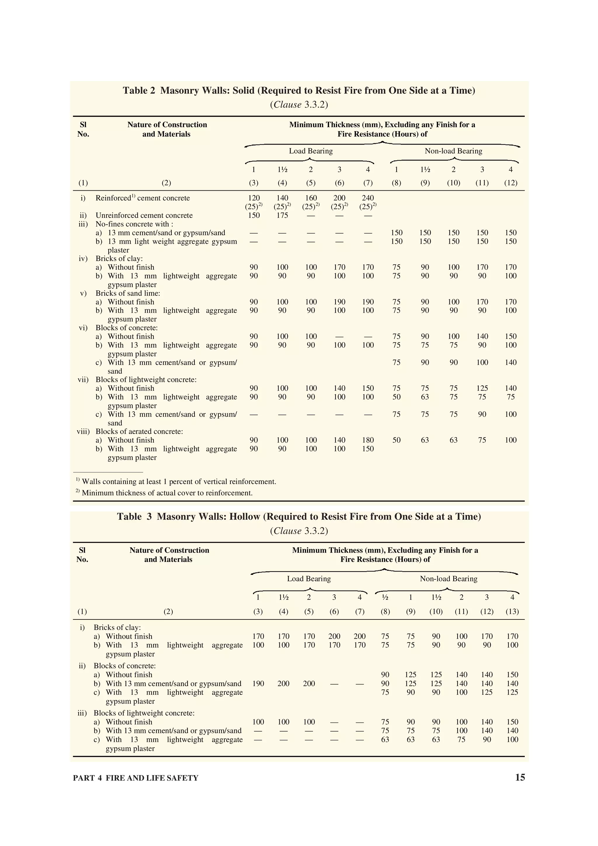
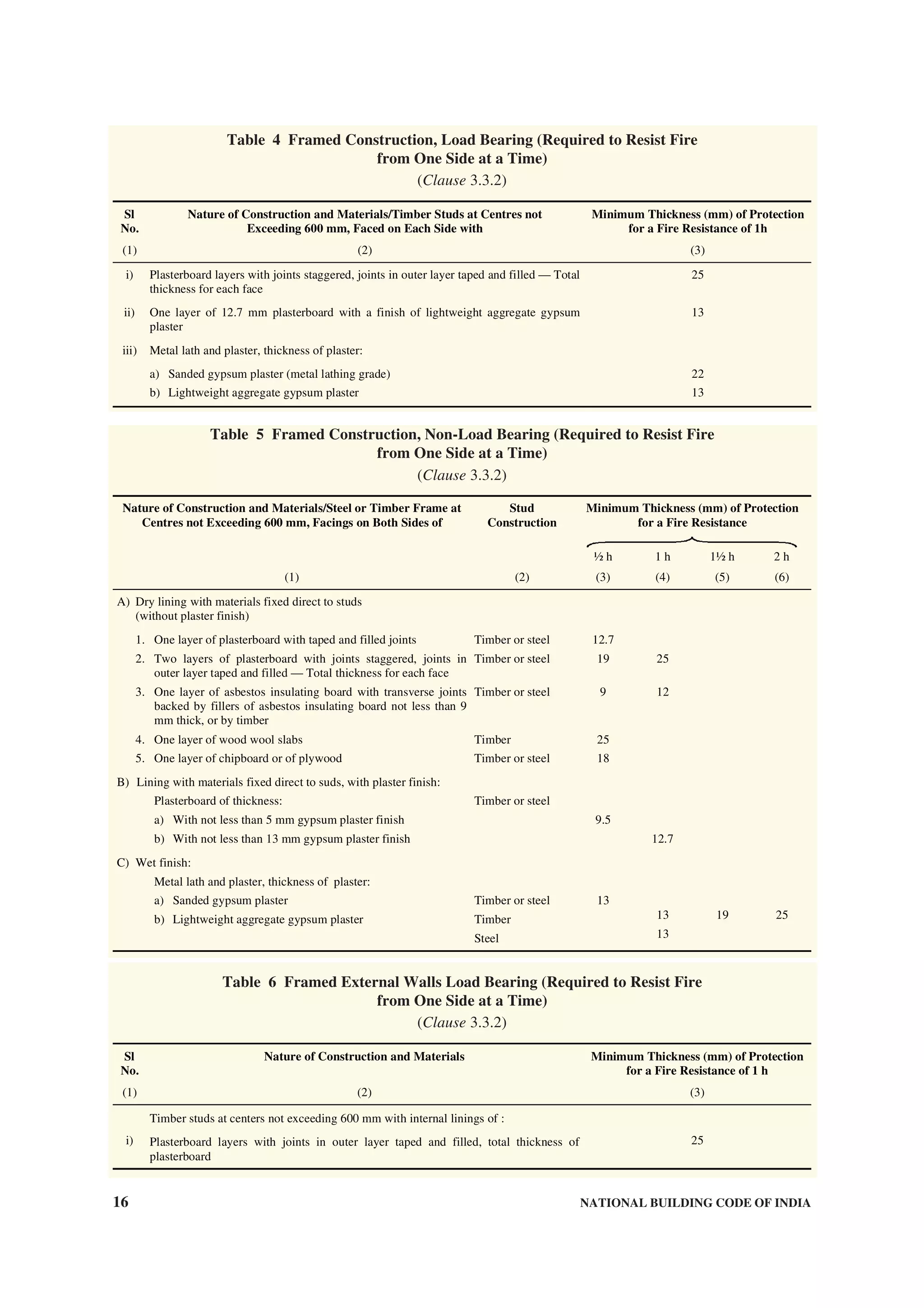
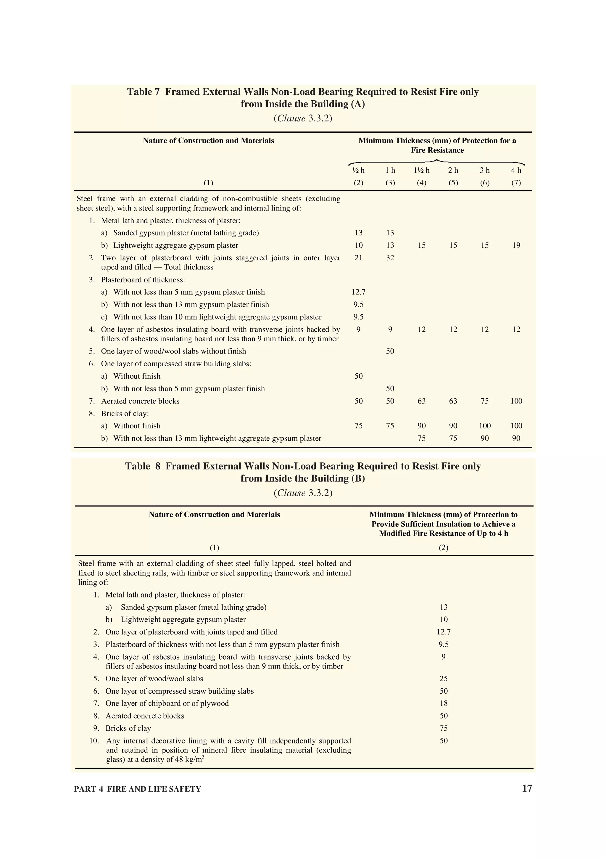
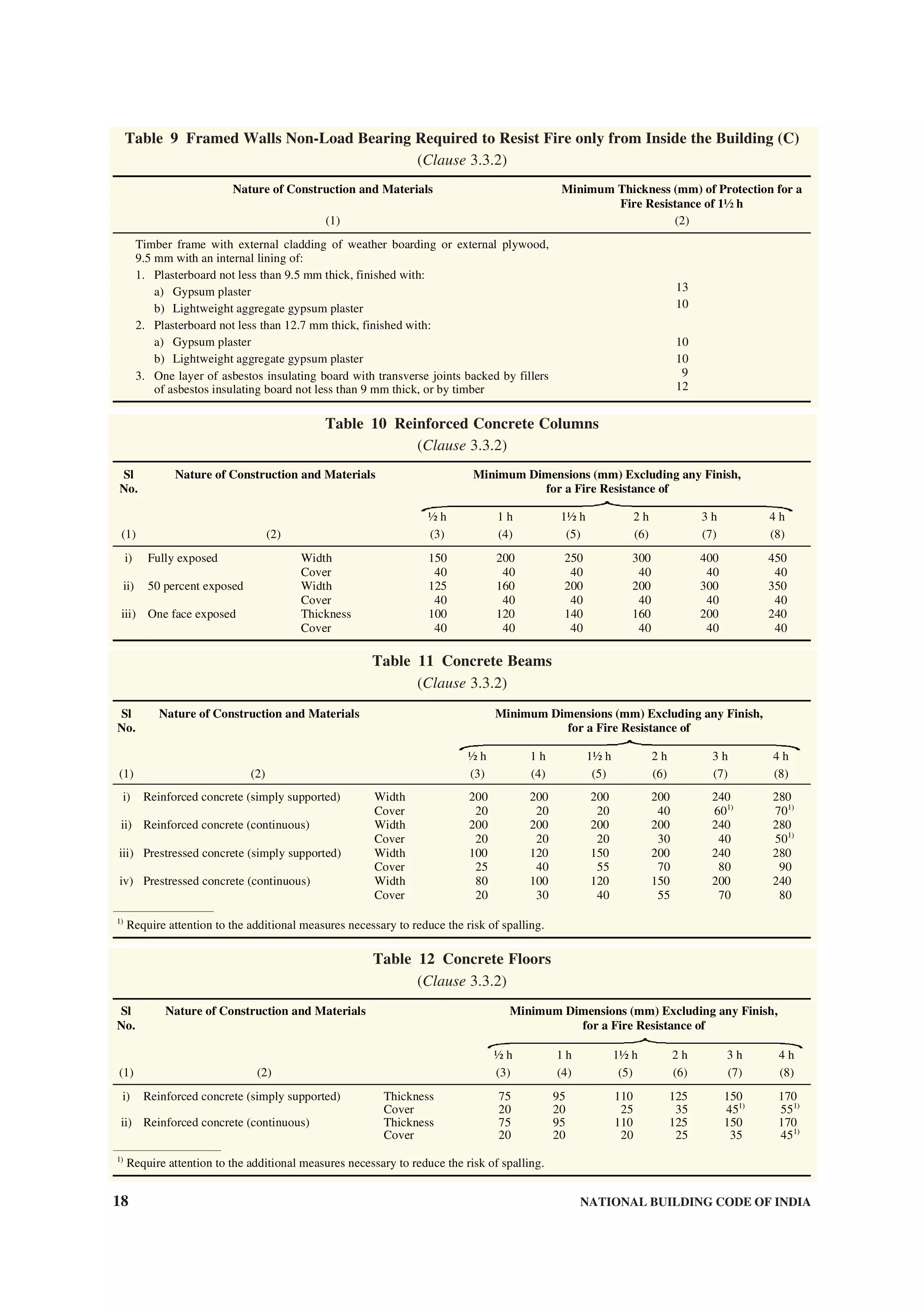
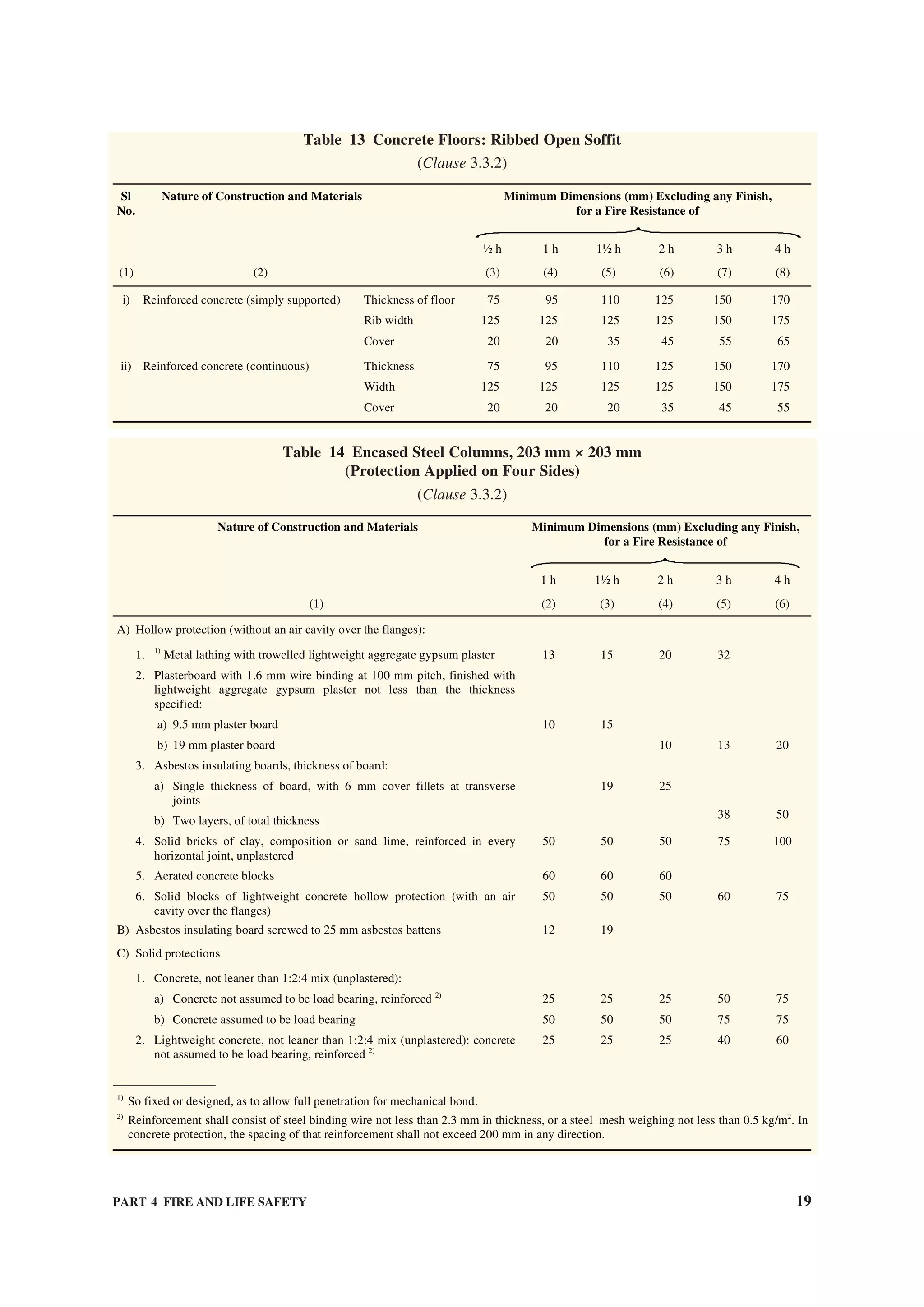

![PART 4 FIRE AND LIFE SAFETY 21
Table 17 Timber Floors — Tongued and Grooved Boarding, or Sheets of Tongued and Grooved
Plywood or Wood Chipboard, of not Less than 15 mm Finished Thickness
(Clause 3.3.2)
Nature of Construction and Materials Minimum Thickness (mm) of Protection for a
Fire Resistance of
1½ h 1 h 2 h
(1) (2) (3) (4)
37 mm (minimum) timber joists with a ceiling of:
1. Timber lathing and plaster, plaster of thickness 15
2. Metal lathing and plaster, thickness of plaster for:
a) Sanded gypsum plaster (metal lathing grade)
b) Lightweight aggregate gypsum plaster
15
13 13 25
3. One layer of plasterboard with taped and filled joints 12.7
4. Two layers of plasterboard with joints staggered, joints in outer layer taped
and filled total thickness
22 31
5. One layer of plasterboard not less than 9.5 mm thick, finish with:
a) Gypsum plaster
b) Sanded gypsum plaster
c) Lightweight aggregate gypsum plaster
5
15
13
6. One layer of plasterboard not less than 12.7 mm thick, finished with:
a) Gypsum plaster
b) Lightweight aggregate gypsum plaster
5
10
7. One layer of asbestos insulating board, with any transverse joints backed by
fillets of asbestos insulating board not less than 9 mm thick, or by timber
9 121)
—————————————
1)
Finished on top with 25 mm minimum thick glass fibre or mineral wool laid between joints.
Table 18 Timber Floors — Any Structurally Suitable Flooring of
Timber or Lignocelluloses Boards
(Clause 3.3.2)
Nature of Construction and Materials Minimum Thickness (mm) of Protection for a
Fire Resistance of
½ h 1 h
(1) (2) (3)
37 mm (minimum) timber joists with a ceiling of:
1. Timber lathing and plaster, plaster of thickness 15
2. Metal lathing and plaster, thickness of plaster for:
a) Sanded gypsum plaster (metal lathing grade)
b) Lightweight aggregate gypsum plaster
15
13 19
3. One layer of plasterboard with joints taped and filled and backed by timber 12.7
4. Two layers of plasterboard with joints staggered, joints in outer layer taped
and filled total thickness
25
5. Two layers of plasterboard, each not less than 9.5 mm thick, joints between
boards staggered and outer layer finished with gypsum plaster
5
6. One layer of plasterboard not less than 9.5 mm thick, finish with:
a) Sanded gypsum plaster
b) Lightweight aggregate gypsum plaster
13
15
7. One layer of plasterboard not less than 12.7 mm thick, finished with:
a) Sanded gypsum plaster
b) Lightweight aggregate gypsum plaster
15
13
8. One layer of asbestos insulating board with any transverse joints backed by
fillets of asbestos insulating board not less than 9 mm thick, or by timber
12
3.3.3 Steel Construction
Load bearing steel beams and columns of buildings
having total covered area of 500 m2
and above shall be
protected against failure/collapse of structure in case
of fire. This could be achieved by use of appropriate
methodology using suitable fire resistance rated
materials alongwith suppression system {see Table 14,
Table 15 and also accepted standard [4(5)]}.](https://image.slidesharecdn.com/is-200203030013/75/NATIONAL-BUILDING-CODE-SP7-133-2048.jpg)
![22 NATIONAL BUILDING CODE OF INDIA
3.4 General Requirements of All Individual
Occupancies
3.4.1 General
All buildings shall satisfy certain requirements which
contribute, individually and collectively, to the safety
of life from fire, smoke, fumes and panic arising from
these or similar causes. There are, however, certain
general principles and common requirements which
are applicable to all or most of the occupancies.
3.4.2 Exceptions and Deviations
Exceptions and deviations to the general provisions of
requirements of individual occupancies are given as
applicable to each type of occupancy in 6.1 to 6.9. In
case of practical difficulty or to avoid unnecessary
hardship, without sacrificing reasonable safety, the
Authority may grant exemptions from the Code.
3.4.3 Occupation of Buildings under Construction
3.4.3.1 A building or portion of the building may be
occupied during construction, repairs, alterations or
additions only if all means of exit and fire protection
measures are in place and continuously maintained for
the occupied part of the building.
3.4.3.2 A high rise building during construction shall
be provided with the following fire protection
measures, which shall be maintained in good working
condition at all the times:
a) Dry riser of minimum 100 mm diameter pipe
with hydrant outlets on the floors constructed
with a fire service inlet to boost the water in the
dry riser and maintenance should be as per the
requirements laid down in good practice [4(6)].
b) Drums filled with water of 2 000 litres capacity
with two fire buckets on each floor; and
c) A water storage tank of minimum 20 000
litres capacity, which may be used for other
construction purposes also.
3.4.4 Maximum Height
Every building shall be restricted in its height above
the ground level and the number of storeys, depending
upon its occupancy and the type of construction. The
height shall be measured as specified in Part 3
‘Development Control Rules and General Building
Requirements’. The maximum permissible height
for any combination of occupancy and types of
construction should necessarily be related to the width
of street fronting the building, or floor area ratios and
the local fire fighting facilities available.
3.4.5 Floor Area Ratio
The comparative floor area ratios for different
occupancies and types of construction are given in
Table 19 (see also Part 3 ‘Development Control Rules
and General Building Requirements’).
Table 19 Comparative Floor Area Ratios for
Occupancies Facing One Public Street
Atleast 9 m Wide
(Clauses 2.6 and 3.4.5)
Type of ConstructionOccupancy
Classification
Type 1 Type 2 Type 3 Type 4
(1) (2) (3) (4) (5)
Residential UL 2.0 1.4 1.0
Educational UL 2.0 1.4 1.0
Institutional UL 1.5 1.0 0.8
Assembly UL 1.0 0.7 0.5
Business UL 2.9 2.3 1.6
Mercantile 8.0 1.8 1.4 1.0
Industrial 7.5 1.9 1.6 1.3
Storage (see Note 5) 6.0 1.5 1.3 1.0
Hazardous (see Note 5) 2.8 1.1 0.9 NP
UL — Unlimited.
NP — Not permitted.
NOTES
1 The FAR values given in this table are subject to overall
restrictions on the heights of buildings in the case of
educational, institutional, assembly, storage and hazardous
occupancies as specified in col 2 of Table 23.
2 This table has been prepared, taking into account the
combustible content in the different occupancies as well as
the fire resistance offered by the type of construction.
3 This table should be modified by the Authority, taking into
account the other aspects as given below:
a) Density in terms of dwelling units per hectare;
b) Traffic considerations;
c) Parking spaces;
d) Local fire fighting facilities; and
e) Water supply, drainage and sanitation requirements.
4 The FAR values specified in this table may be increased
by 20 percent for the following services:
a) A basement or cellar space under a building constructed
on stilts and used as a parking space and air-
conditioning plant room used as accessory to the
principal use;
b) Watchman’s booth, pumphouse, garbage shaft, electric
cabin or sub-station and other utility structures meant
for the services of the building under considerations;
c) Projections and accessory buildings as specifically
exempted under the Code; and
d) Staircase room and lift rooms above the topmost storey;
architectural feature; and chimneys and elevated tanks
of dimensions as permissible under the Code; the area
of the lift shaft shall be taken only on one floor.
5 In so far as single storey storage and hazardous occupancies
are concerned, they would be further governed by volume to
plot area ratio (VPR) to be decided by the Authority.
3.4.5.1 Each portion of a building, which is separated
by one or more continuous fire resisting walls, having
a fire resistance of not less than 2 h, extending from
the foundation to 1 m above the roof at all points, may](https://image.slidesharecdn.com/is-200203030013/75/NATIONAL-BUILDING-CODE-SP7-134-2048.jpg)
![PART 4 FIRE AND LIFE SAFETY 23
be considered to be a separate building for the
calculation of maximum permissible height and floor
area, provided openings, if any, in the separating
wall are also protected by fire assemblies of not less
than 2 h.
3.4.6 Open Spaces
The open spaces around or inside a building shall
conform to the requirements of Part 3 ‘Development
Control Rules and General Building Requirements’.
3.4.6.1 For high rise buildings, the following
additional provisions of means of access to the building
shall be ensured (see Part 3 ‘Development Control
Rules and General Building Requirements’):
a) The width of the main street on which the
building abuts shall not be less than 12 m and
one end of this street shall join another street
not less than 12 m in width;
b) The road shall not terminate in a dead end;
except in the case of residential building, up
to a height of 30 m.
c) The compulsory open spaces around the
building shall not be used for parking; and
d) Adequate passageway and clearances
required for fire fighting vehicles to enter the
premises shall be provided at the main
entrance; the width of such entrance shall be
not less than 4.5 m. If an arch or covered gate
is constructed, it shall have a clear head-room
of not less than 5 m.
3.4.7 Mixed Occupancy
When any building is used for more than one type of
occupancy, then in so far as fire safety is concerned, it
shall conform to the requirements for the occupancies
of higher hazard. Unless the high hazard area is
separated by separating walls of 4 h rating, the
occupancies shall not be treated individually.
3.4.8 Openings in Separating Walls and Floors
At the time of designing openings in separating walls
and floors, particular attention shall be paid to all such
factors as will limit fire spread through these openings
and maintain fire rating of the structural member.
3.4.8.1 For Types 1 to 3 construction, a doorway or
opening in a separating wall on any floor shall be
limited to 5.6 m2
in area with a maximum height/width
of 2.75 m. Every wall opening shall be protected with
fire-resisting doors having the fire rating of not less
than 2 h in accordance with accepted standard [4(7)].
All openings in the floors shall be protected by vertical
enclosures extending above and below such openings,
the walls of such enclosures having a fire resistance of
not less than 2 h and all openings therein being
protected with a fire-resisting assembly as specified
in 3.4.9.
3.4.8.2 For Type 4 construction, openings in the
separating walls or floors shall be fitted with 2 h fire-
resisting assemblies.
3.4.8.3 Openings in walls or floors which are
necessary to be provided to allow passages of all
building services like cables, electrical wirings,
telephone cables, plumbing pipes, etc, shall be
protected by enclosure in the form of ducts/shafts
having a fire resistance not less than 2 h. The inspection
door for electrical shafts/ducts shall be not less than
2 h and for other services shafts/ducts, the same shall
have fire resistance not less than 1 h. Medium and low
voltage wiring running in shafts/ducts, shall either be
armoured type or run through metal conduits. Further,
the space between the conduits pipes and the walls/
slabs shall be filled in by a filler material having fire
resistance rating of not less than 1 h.
NOTE — In the case of buildings where it is necessary to lower
or lift heavy machinery or goods from one floor to the other, it
may be necessary to provide larger openings in the floor. Such
openings shall be provided with removable covers which shall
have the same strength and fire resistance as the floor.
3.4.8.4 Vertical opening
Every vertical opening between the floors of a building
shall be suitably enclosed or protected, as necessary,
to provide the following:
a) Reasonable safety to the occupants while
using the means of egress by preventing
spread of fire, smoke, or fumes through
vertical openings from floor to floor to allow
occupants to complete their use of the means
of egress. Further it shall be ensured to
provide a clear height of 2 100 mm in the
passage/escape path of the occupants.
b) Limitation of damage to the building and its
contents.
3.4.9 Fire Stop or Enclosure of Openings
Where openings are permitted, they shall not exceed
three-fourths the area of the wall in the case of an
external wall and they shall be protected with fire
resisting assemblies or enclosures having a fire
resistance equal to that of the wall or floor in which
these are situated. Such assemblies and enclosures shall
also be capable of preventing the spread of smoke or
fumes through the openings so as to facilitate the safe
evacuation of building in case of a fire {see also
accepted standard [4(8)]}.
3.4.10 Electrical Installations
For requirements regarding electrical installations from
the point of view of fire safety, reference may be made](https://image.slidesharecdn.com/is-200203030013/75/NATIONAL-BUILDING-CODE-SP7-135-2048.jpg)
![24 NATIONAL BUILDING CODE OF INDIA
to good practice [4(9)] (see also Part 8 ‘Building
Services, Section 2 Electrical and Allied Installations’).
3.4.11 Air-conditioning and Ventilation
Air-conditioning and ventilation requirements of
different rooms or areas in any occupancy shall be as
given in Part 8 ‘Building Services, Section 1 Lighting
and Ventilation and Section 3 Air-conditioning,
Heating and Mechanical Ventilation’.
3.4.11.1 Air-conditioning and ventilating systems
shall be so installed and maintained as to minimize the
danger of spread of fire, smoke or fumes from one
floor to other or from outside to any occupied building
or structure (see C-1.17).
3.4.11.2 Air-conditioning and ventilating systems
circulating air to more than one floor or fire area shall be
provided with dampers designed to close automatically
in case of fire and thereby preventing spread of fire or
smoke and shall be in accordance with the accepted
standard [4(10)]. Such a system shall also be provided
with automatic controls to stop fans in case of fire, unless
arrangedtoremovesmokefromafire,inwhichcasethese
shall be designed to remain in operation.
3.4.11.3 Air-conditioning system serving large places
of assembly (over 1 000 persons), large departmental
stores or hotels with over 100 rooms in a single block
shall be provided with effective means for preventing
circulation of smoke through the system in the case of
a fire in air filters or from other sources drawn into the
system, and shall have smoke sensitive devices for
actuation in accordance with the accepted standards
[4(11)].
3.4.11.4 From fire safety point of view, separate air
handling units for the various floors shall be provided
so as to avoid the hazards arising from spread of fire
and smoke through the air-conditioning ducts. The
requirements of air-conditioning ducts shall be in
accordance with good practice [4(12)].
3.4.11.5 For normal operation, air changes schedule
shall be as given in Part 8 ‘Building Services, Section 3
Air-conditioning, Heating and Mechanical Ventilation’.
3.4.12 Smoke Venting
3.4.12.1 Smoke venting facilities for safe use of exits
in windowless buildings, underground structures, large
area factories, hotels and assembly buildings (including
cinema halls) shall be automatic in action with manual
controls in addition.
3.4.12.2 Natural draft smoke venting shall utilize roof
vents or vents in walls at or near the ceiling level; such
vents shall be normally open, or, if closed, shall be
designed for automatic opening in case of fire, by
release of smoke sensitive devices.
3.4.12.3 Where smoke venting facilities are installed
for purposes of exit safety, these shall be adequate to
prevent dangerous accumulation of smoke during the
period of time necessary to evacuate the area served,
using available exit facilities with a margin of safety to
allow for unforeseen contingencies. It is recommended
that smoke exhaust equipment should have a minimum
capacity of 12 air changes per hour. Where mechanical
venting is employed, it shall be firesafe.
3.4.12.4 The discharge apertures of all natural draft
smoke vents shall be so arranged as to be readily
accessible for opening by fire service personnel.
3.4.12.5 Power operated smoke exhausting systems
shall be substituted for natural draft vents only by
specific permission of the Authority.
3.4.13 Heating
Installation of chimney and heating apparatus shall be
in accordance with good practice [4(13)].
3.4.14 Additional Precautions
In addition to the factors covered by 3.4.2 to 3.4.12
there are certain aspects, applicable to particular
occupancies only, which may effect the spread of
fumes and thus the safe evacuation of the building in
case of fire. Some such aspects are:
a) interior finish and decoration;
b) seating, aisles, railings, turnstiles and
revolving doors in places of assembly;
c) service equipment and storage facilities in
buildings other than storage buildings; and
d) hazards on stage, in waiting spaces, projection
booths, etc, in theatres and cinemas.
3.4.15 Surface Interior Finishes
3.4.15.1 The use of combustible surface finishes on
walls (including facade of the building) and ceilings
affects the safety of the occupants of a building. Such
finishes tend to spread the fire and even though the
structural elements may be adequately fire resistant,
serious danger to life may result. It is, therefore,
essential to have adequate precautions to minimize
spread of flame on wall, facade of building and ceiling
surfaces.
The finishing materials used for various surfaces and
décor shall be such that it shall not generate toxic
smoke/fumes.
3.4.15.2 The susceptibility to fire of various types
of wall surfaces is determined in terms of the rate of
spread of flame. Based on the rate of spread of flame,
surfacing material shall be considered as divided into
four classes as follows {see also good practice
[4(14)]}.](https://image.slidesharecdn.com/is-200203030013/75/NATIONAL-BUILDING-CODE-SP7-136-2048.jpg)
![PART 4 FIRE AND LIFE SAFETY 25
Class 1 Surfaces of very low flame spread.
Class 2 Surfaces of low flame spread.
Class 3 Surfaces of medium flame spread.
Class 4 Surfaces of rapid flame spread.
3.4.15.3 The uses for which surface materials falling
into various classes shall be adopted in building
construction are given below:
Class 1 Class 2 Class 3
May be
used in any
situation
May be used in
any situation,
except on walls,
facade of the
building,
staircase and
corridors
May be used only
in living rooms and
bed rooms (but not
in rooms on the
roof) and only as a
lining to solid walls
and partitions; not
on staircases or
corridors or facade
of the building.
NOTE — Panelling (lining) shall be permitted in a limited
area. It shall not be permitted in a vestibule.
3.4.15.4 Materials of Class 4 which include untreated
wood fibreboards may be used with due fire retardant
treatment as ceiling lining, provided the ceiling is at
least, 2.4 m from the top surface of the floor below,
and the wall surfaces conform to requirements of class
[see Note under 3.4.15.3] Class 4 materials shall not
be used in kitchens, corridors and staircases. Some
materials contain bitumen and, in addition to risk from
spread of fire, emit dense smoke on burning; such
materials shall be excluded from use under these
conditions and shall also not be used for construction
of ceiling where the plenum is used for return air in
air-conditioned buildings [see also 5.1.7(m)].
3.4.15.5 When frames, walls, partitions or floors are
lined with combustible materials, the surfaces on both
sides of the materials shall conform to the appropriate
class, because there is considerable danger from fire
starting and rapidly spreading within the concealed
cavity unknown to the occupants whose escape may
be hampered there by. For detailed information on
materials and details of construction with their fire-
resistance rating, reference may be made to good
practice [4(15)].
3.4.16 Glazing
3.4.16.1 Building of Types 1 to 4 construction shall
employ one of the two types of glazing described
in 3.4.16.2 and 3.4.16.3 except that Type 4 construction
may have the alternative of hardwood sashes or frames
or both.
3.4.16.2 Wired glass shall comply with the following
requirements:
a) Wired glass — The wired glass shall be of
minimum half hour fire resistance rating.
b) Sashes and frames — The sashes or frames
or both shall be entirely of iron or other
suitable metal such as stainless steel, securely
bolted or keyed into the wall, except in the
case of panels in internal doors.
c) Setting of glass — The panels of glass shall
be set in rebates or grooves not less than
6.0 mm in width or depth, with due allowance
for expansion, and shall be secured by hard
metal fastenings to the sashes or frames
independently of any cement or putty used
for weather-proofing purposes.
3.4.16.3 Electro-copper glazing shall comply with the
following requirements:
a) Electro-copper glazing — The electro-copper
glazing shall be of minimum half hour fire
resistance rating.
b) Sashes and frames — The sashes or frames
or both shall be entirely of iron or other hard
metal, securely bolted or keyed into the wall,
except when in panels in internal doors.
c) Fixing of sectional lights — The sectional
lights shall be set in rebate or grooves not less
than 6.5 mm in width or depth, with due
allowance for expansion and shall be secured
by hard metal fastenings to the sashes or
frames independently of any lead, cement or
putty used for weather-proofing purposes.
3.4.16.4 Maximum permissible area shall be 5 m2
for
protection by wired glass or electro-copper glazing.
3.4.16.5 Casement
Hard metal casements, not exceeding 0.8 m2
fitted with
wired glass or electro-copper glazing in accordance
with 3.4.16.2 and 3.4.16.3, secured to the frames by
hard metal hinges not more than 600 mm apart and by
fastening at top, centre and bottom shall be permissible.
3.4.17 Skylights
3.4.17.1 Wired glass for skylights or monitor lights
shall comply with the following requirements:
a) Wired glass for skylights or monitor lights —
The wired glass for skylights or monitor lights
shall be of minimum half hour fire resistance
rating.
b) Frames and glazing — The frame shall be
continuous and divided by bars spaced at not
more than 700 mm centres. The frame and
bars shall be of iron or other hard metal, and
supported on a curb either of metal or of wood
covered with sheet metal. The toughened glass](https://image.slidesharecdn.com/is-200203030013/75/NATIONAL-BUILDING-CODE-SP7-137-2048.jpg)
![26 NATIONAL BUILDING CODE OF INDIA
shall be secured by hard metal fastenings to
the frame and bars independently of any lead,
cement or putty used for weather-proofing
purposes.
3.4.18 Louvers
Louvers wherever provided shall be of minimum half
hour fire resistance rating.
3.4.19 Glass of facade for high rise buildings, etc shall
be of minimum 1 h fire resistance rating.
4 LIFE SAFETY
4.1 General
Every building shall be so constructed, equipped,
maintained and operated as to avoid undue danger to
the life and safety of the occupants from fire, smoke,
fumes or panic during the time period necessary for
escape.
4.2 General Exit Requirements
4.2.1 Anexitmaybeadoorway;corridor;passageway(s)
to an internal staircase, or external staircase, or to a
VERANDAH or terrace(s), which have access to the
street, or to the roof of a building or a refuge area. An
exit may also include a horizontal exit leading to an
adjoining building at the same level.
4.2.2 Lifts and escalators shall not be considered as
exits.
4.2.3 Every exit, exit access or exit discharge shall be
continuously maintained free of all obstructions or
impediments to full use in the case of fire or other
emergency.
4.2.4 Every building meant for human occupancy shall
be provided with exits sufficient to permit safe escape
of occupants, in case of fire or other emergency.
4.2.5 In every building or structure, exits shall comply
with the minimum requirements of this part, except
those not accessible for general public use.
4.2.6 No building shall be so altered as to reduce the
number, width or protection of exits to less than that
required.
4.2.7 Exits shall be clearly visible and the route to
reach the exits shall be clearly marked and signs posted
to guide the occupants of the floor concerned. Signs
shall be illuminated and wired to an independent
electrical circuit on an alternative source of supply.
The sizes and colours of the exit signs shall be in
accordance with good practice [4(16)]. The colour of
the exit signs shall be green.
NOTE — This provision shall not apply to A-2 and A-4
occupancies less than 15 m in height.
4.2.8 The floors of areas covered for the means of exit
shall be illuminated to values not less than 1 ft candle
(10 lux) at floor level. In auditoriums, theatres, concert
halls and such other places of assembly, the
illumination of floor exit/access may be reduced during
period of performances to values not less than 1/5 ft
candle (2 lux).
4.2.9 Fire doors with 2 h fire resistance shall be
provided at appropriate places along the escape route
and particularly at the entrance to lift lobby and stair
well where a ‘funnel or flue effect’ may be created,
inducing an upward spread of fire to prevent spread of
fire and smoke.
4.2.10 All exits shall provide continuous means of
egress to the exterior of a building or to an exterior
open space leading to a street.
4.2.11 Exits shall be so arranged that they may be
reached without passing through another occupied
unit.
4.3 Occupant Load
For determining the exits required, the number of
persons within any floor area or the occupant load shall
be based on the actual number of occupants, but in no
case less than that specified in Table 20.
4.3.1 Mezzanine
The occupant load of a mezzanine floor discharging
to a floor below shall be added to that floor occupancy
and the capacity of the exits shall be designed for the
total occupancy load thus established.
4.4 Capacities of Exits
4.4.1 The unit of exit width, used to measure the
capacity of any exit, shall be 500 mm. A clear width
of 250 mm shall be counted as an additional half unit.
Clear widths less than 250 mm shall not be counted
for exit width.
NOTE — The total occupants from a particular floor must
evacuate within 2½ minutes for Type 1 construction,
1½ minutes for Type 2 construction and 1 minute for Type 3
construction. Size of the exit door/exitway shall be calculated
accordingly keeping in view the travel distance as per
Table 22.
4.4.2 Occupants per unit exit width shall be in
accordance with Table 21.
4.4.3 Horizontal Exit Allowance
When horizontal exit is provided in buildings of
mercantile, storage, industrial, business and assembly
occupancies, the capacity per storey per unit width of
exit of stairways in Table 21 may be increased by 50
percent and in buildings of institutional occupancy it
may be increased by 100 percent.](https://image.slidesharecdn.com/is-200203030013/75/NATIONAL-BUILDING-CODE-SP7-138-2048.jpg)
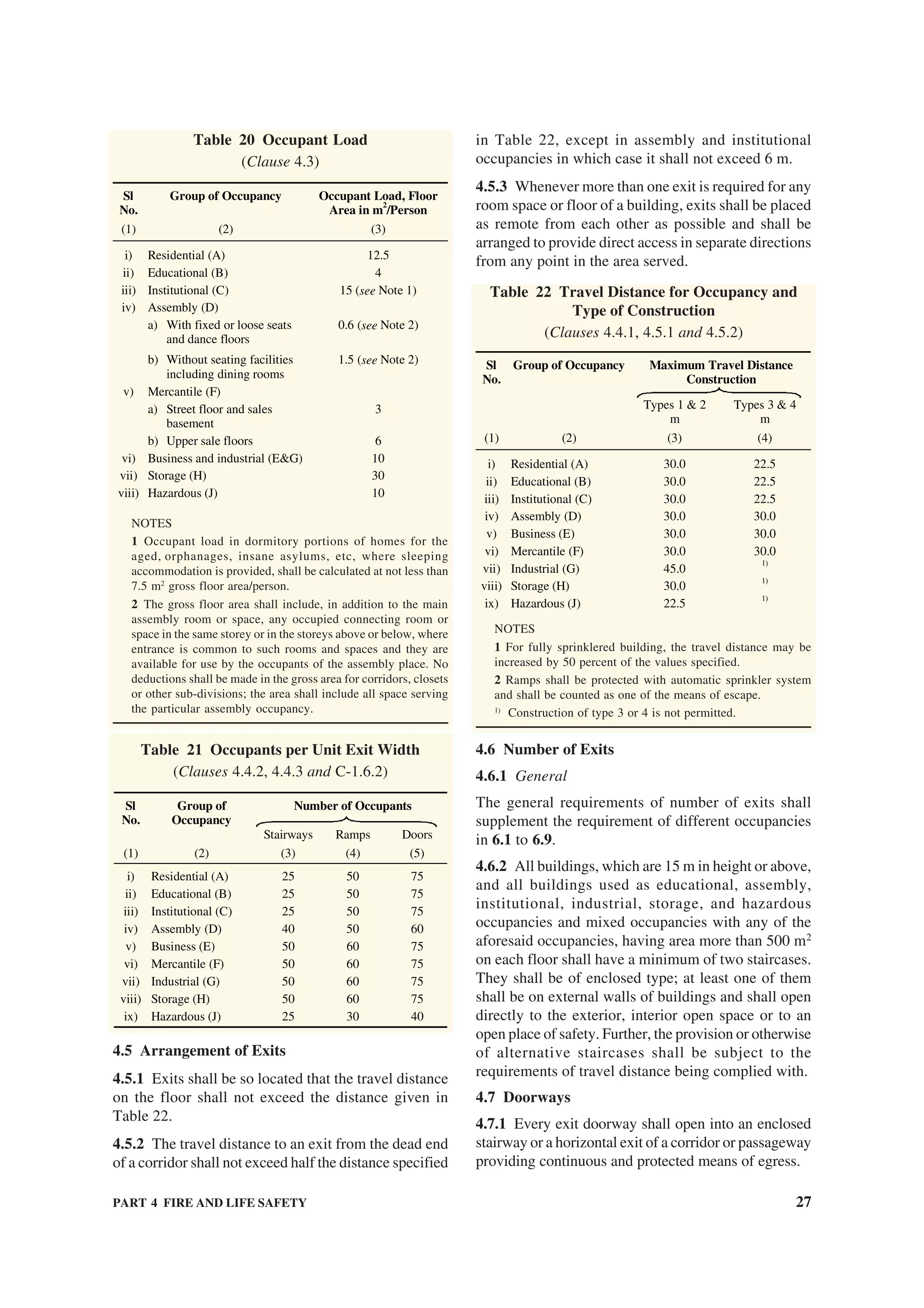
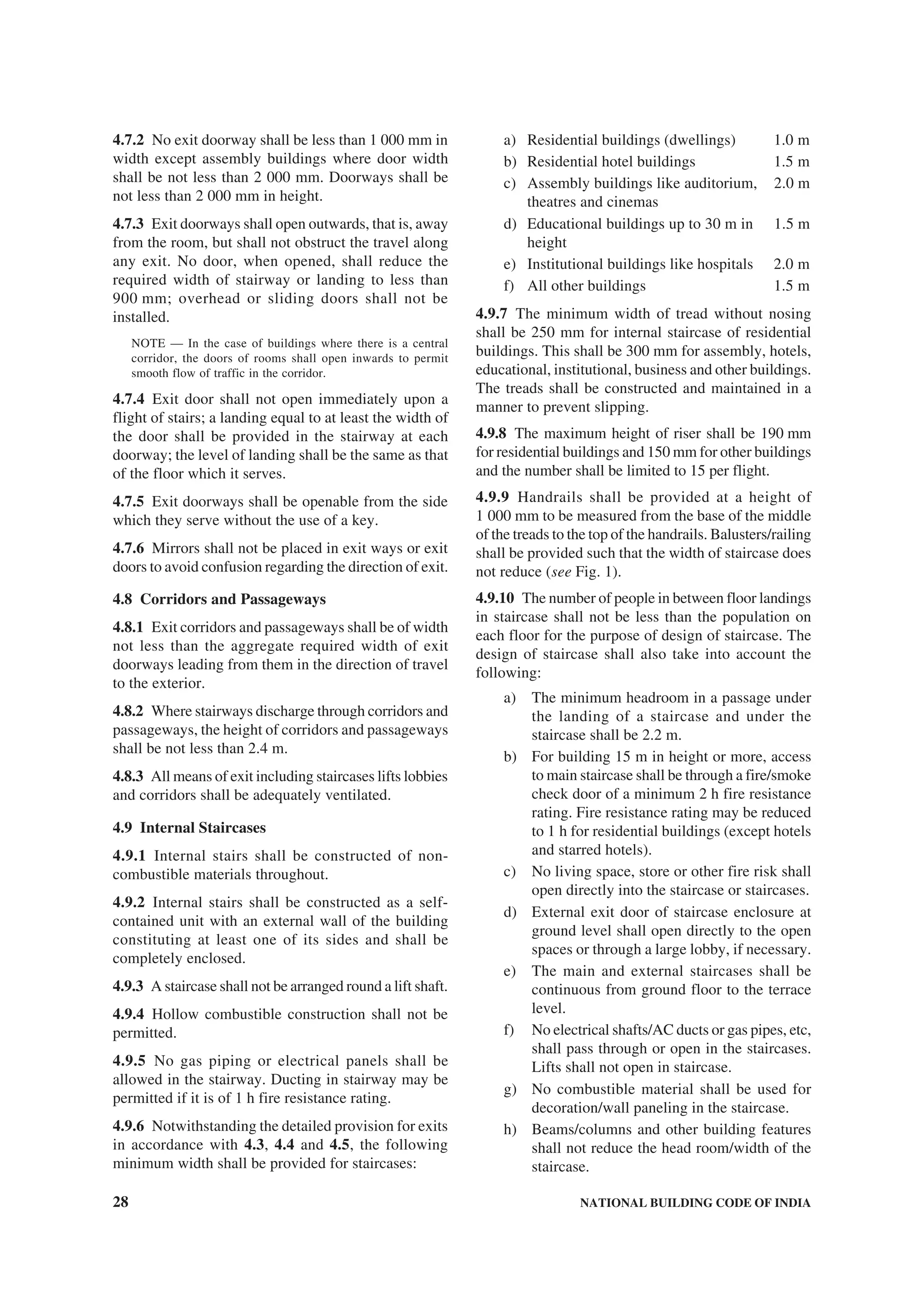
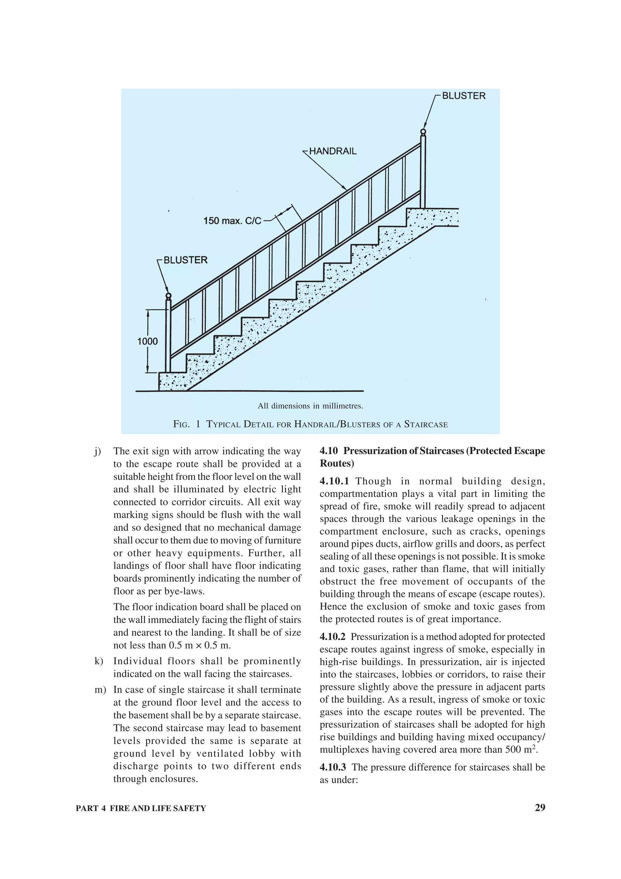
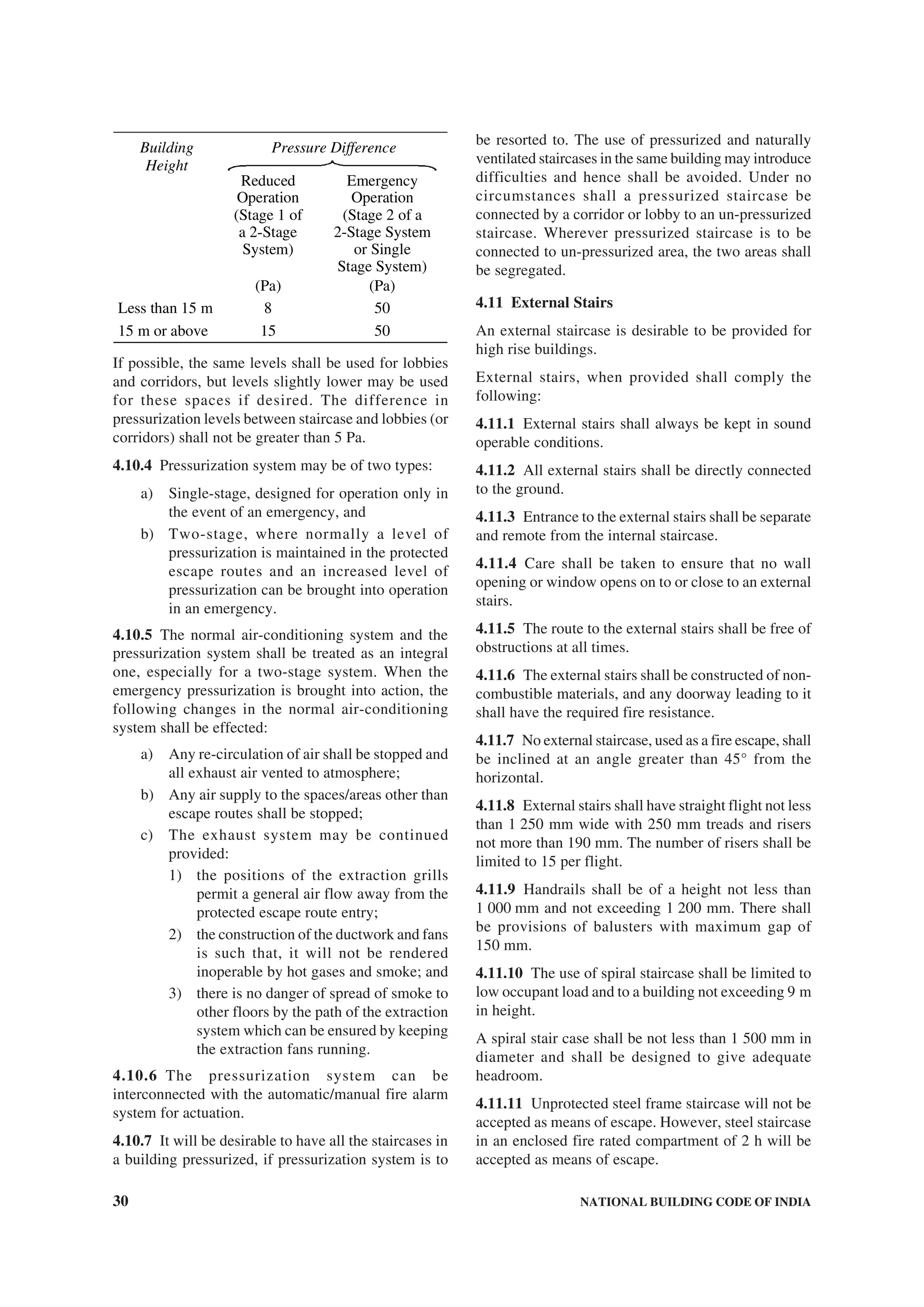
![PART 4 FIRE AND LIFE SAFETY 31
4.12 Horizontal Exits
4.12.1 The width of horizontal exit shall be same as
for the exit doorways.
4.12.2 A horizontal exit shall be equipped with at least
one fire/smoke door of minimum 1 h fire resistance,
of self-closing type. Further, it is required to have direct
connectivity to the fire escape staircase for evacuation.
4.12.3 For buildings more than 24 m in height, refuge
area of 15 m2
or an area equivalent to 0.3 m2
per person
to accommodate the occupants of two consecutive
floors, whichever is higher, shall be provided as under:
The refuge area shall be provided on the periphery of
the floor or preferably on a cantilever projection and
open to air at least on one side protected with suitable
railings.
a) For floors above 24 m and Up to 39 m —
One refuge area on the floor immediately
above 24 m.
b) For floors above 39 m — One refuge area on
the floor immediately above 39 m and so on
after every 15 m. Refuge area provided in
excess of the requirements shall be counted
towards FAR.
NOTE — Residential flats in multi-storied building with
balcony, need not be provided with refuge area,
however flats without balcony shall provide refuge area
as given above.
4.12.4 Where there is a difference in level between
connected areas for horizontal exits, ramps, not more
than 1 in 10 m slope shall be provided; steps shall not
be used.
4.12.5 Doors in horizontal exits shall be openable at
all times from both sides.
4.13 Fire Tower
Fire towers are the preferred type of escape route for
storeyed buildings and these shall be considered as the
safest route for escape. Their number, location and size
shall depend on the building concerned, and its
associated escape routes.
4.13.1 In high rise buildings with over 8 storeys or
24 m in height, at least one required means of egress
shall preferably be a fire tower.
4.13.2 The fire towers shall be constructed of walls
with a 2 h fire resistance rating without openings other
than the exit doorways, with platforms, landings and
balconies having the same fire-resistance rating.
4.14 Ramps
4.14.1 Ramps shall comply with all the applicable
requirements for stairways regarding enclosure,
capacity and limiting dimensions except where
specified in 6.1 to 6.9 for special uses and occupancies.
4.14.2 The slope of a ramp shall not exceed 1 in 10.
In certain cases steeper slopes may be permitted but in
no case greater than 1 in 8.
4.14.3 For all slopes exceeding 1 in 10 and wherever
the use is such as to involve danger of slipping, the
ramp shall be surfaced with approved non-slipping
material.
4.15 Fire Lifts
4.15.1 Where applicable, fire lifts shall be provided
with a minimum capacity for 8 passengers and fully
automated with emergency switch on ground level. In
general, buildings 15 m in height or above shall be
provided with fire lifts.
4.15.2 In case of fire, only fireman shall operate the fire
lift. In normal course, it may be used by other persons.
4.15.3 Each fire lift shall be equipped with suitable
inter-communication equipment for communicating
with the control room on the ground floor of the
building.
4.15.4 The number and location of fire lifts in a
building shall be decided after taking into consideration
various factors like building population, floor area,
compartmentation, etc.
4.16 Emergency and Escape Lighting
4.16.1 Emergency lighting shall be powered from a
source independent of that supplying the normal
lighting [see good practice [4(17)].
Escape lighting shall be capable of:
a) Indicating clearly and unambiguously the
escape routes,
b) Providing adequate illumination along such
routes to allow safe movement of persons
towards and through the exits,
c) Ensuring that fire alarm call points and fire-
fighting equipments provided along the
escape routes can be readily located.
4.16.2 The horizontal luminance at floor level on the
centreline of an escape route shall be not less than
10 lux. In addition, for escape routes up to 2 m wide,
50 percent of the route width shall be lit to a minimum
of 5 lux.
4.16.3 The emergency lighting shall be provided to
be put on within 1 s of the failure of the normal lighting
supply.
4.16.4 Escape lighting luminaries should be sited to
cover the following locations:](https://image.slidesharecdn.com/is-200203030013/75/NATIONAL-BUILDING-CODE-SP7-143-2048.jpg)
![32 NATIONAL BUILDING CODE OF INDIA
a) Near each intersection of corridors,
b) at each exit door,
c) Near each change of direction in the escape
route,
d) Near each staircase so that each flight of stairs
receives direct light,
e) Near any other change of floor level,
f) Outside each final exit and close to it,
g) Near each fire alarm call point,
h) Near fire-fighting equipment, and
j) To illuminate exit and safety signs as required
by the enforcing authority.
NOTE — For the purposes of this clause ‘near’ is
normally considered to be within 2 m measured
horizontally.
4.16.5 Emergency lighting systems shall be designed
to ensure that a fault or failure in any one luminaire
does not further reduce the effectiveness of the
system.
4.16.6 The luminairies shall be mounted as low as
possible, but at least 2 m above the floor level.
4.16.7 Signs are required at all exits, emergency
exits and escape routes, which should comply with
the graphic requirements of the relevant Indian
Standards.
4.16.8 Emergency lighting luminaires and their fittings
shall be of non-flammable type.
4.16.9 It is essential that the wiring and installation of
the emergency lighting systems are of high quality so
as to ensure their perfect serviceability at all times.
4.16.10 The emergency lighting system shall be
capable of continuous operation for a minimum
duration of 1 h and 30 m even for the smallest
premises.
4.16.11 The emergency lighting system shall be well
maintained by periodical inspections and tests so as to
ensure their perfect serviceability at all times.
4.17 Illumination of Means of Exit
Staircase and corridor lights shall conform to the
following:
a) The staircase and corridor lighting shall be
on separate circuits and shall be independently
connected so that it could be operated by one
switch installation on the ground floor easily
accessible to fire fighting staff at any time
irrespective of the position of the individual
control of the light points, if any. It should be
of miniature circuit breaker type of switch so
as to avoid replacement of fuse in case of
crisis;
b) Staircase and corridor lighting shall also
be connected to alternative supply. The
alternative source of supply may be provided
by battery continuously trickle charged from
the electric mains; and
c) Suitable arrangements shall be made by
installing double throw switches to ensure that
the lighting installed in the staircase and the
corridor does not get connected to two sources
of supply simultaneously. Double throw
switch shall be installed in the service room
for terminating the stand-by supply.
4.18 Fire Detection and Warning
In buildings of such size, arrangement or occupancy
where a fire may not itself provide adequate warning
to occupants, automatic fire detection and alarm
facilities shall be provided, where necessary, to warn
occupants early of the existence of fire, so that they
may escape, and to facilitate the orderly conduct of
fire exit drills.
4.18.1 The fire detection system shall be in accordance
with accepted standards [4(18)]. Guidelines for
selection of various types of fire detectors for different
occupancies and their installation and maintenance
shall be in accordance with [4(19)].
4.18.2 The requirements of fire detection and alarm
systems are covered for each occupancy in Table 23
and under 6.1 to 6.9; attention is also drawn to such
requirements in case of high rise buildings (15 m or
more in height) as given in Annex C.
5 FIRE PROTECTION
5.1 Fire Extinguishers/Fixed Fire Fighting
Installations
5.1.1 All buildings depending upon the occupancy use
and height shall be protected by fire extinguishers, wet
riser, down-comer, automatic sprinkler installation,
high/medium velocity water spray, foam, gaseous or
dry powder system in accordance with the provisions
of 5.1.2 to 5.1.9.
5.1.2 These fire extinguishers/fixed installations shall
be in accordance with accepted standards [4(20)]. The
typical requirements of fire extinguishers/wet riser/
down-comer installation and capacity of water storage
tanks and fire pumps, etc shall be as specified in
Table 23. The requirements regarding size of mains/
risers shall be as given in Table 24. The typical
arrangements of down-comer and wet riser installations
are shown in Fig. 2 and Fig. 3. The wet riser shall be
designed for zonal distribution ensuring that unduly
high pressures are not developed in risers and hose-
pipes.](https://image.slidesharecdn.com/is-200203030013/75/NATIONAL-BUILDING-CODE-SP7-144-2048.jpg)
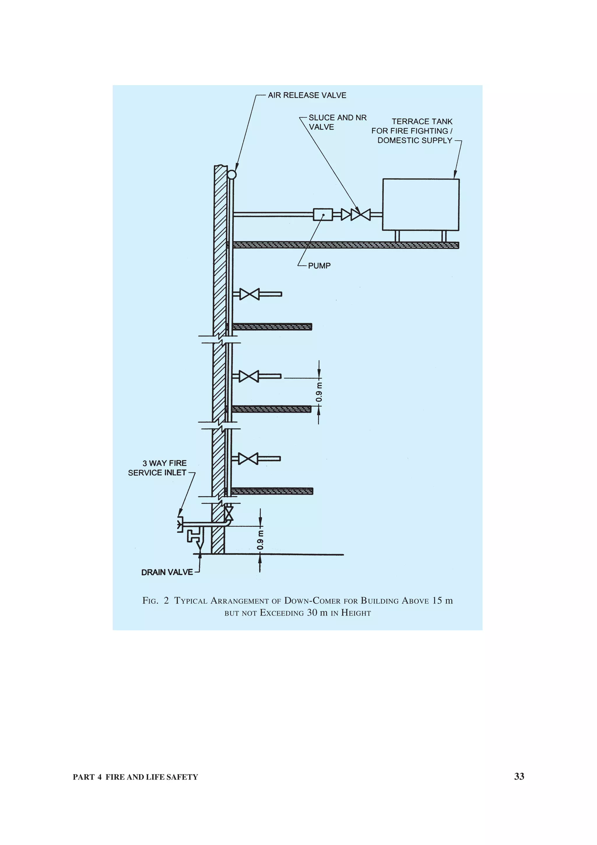
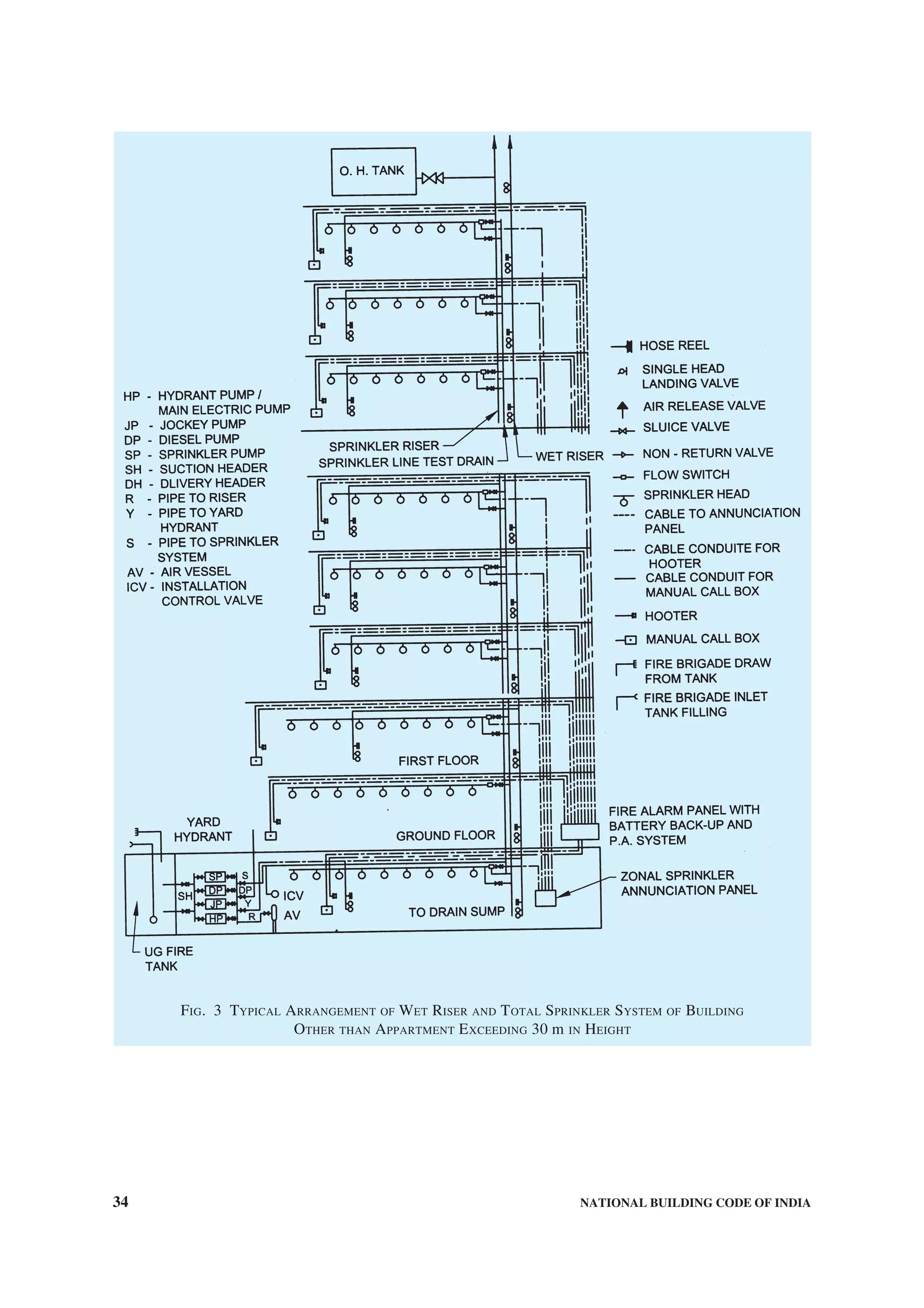
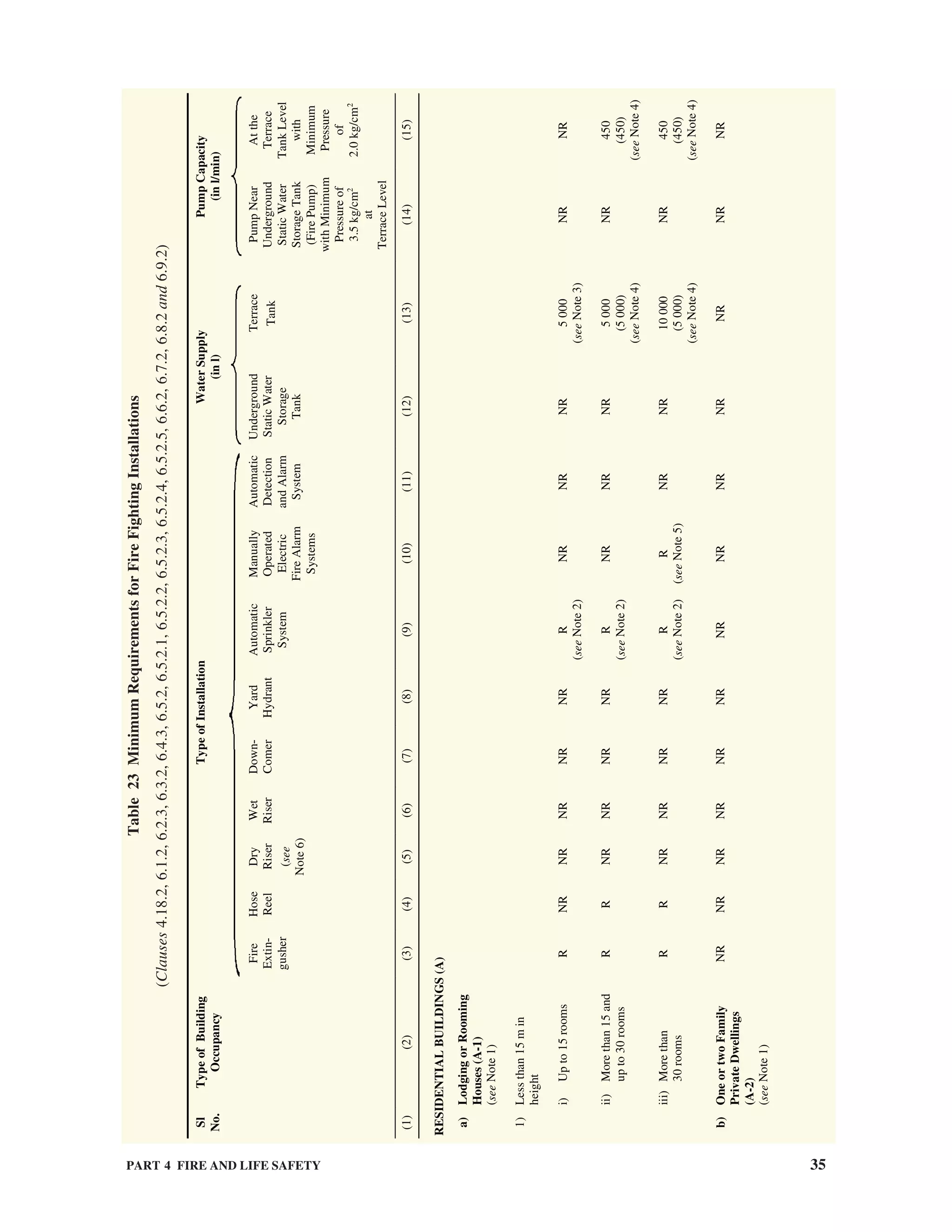
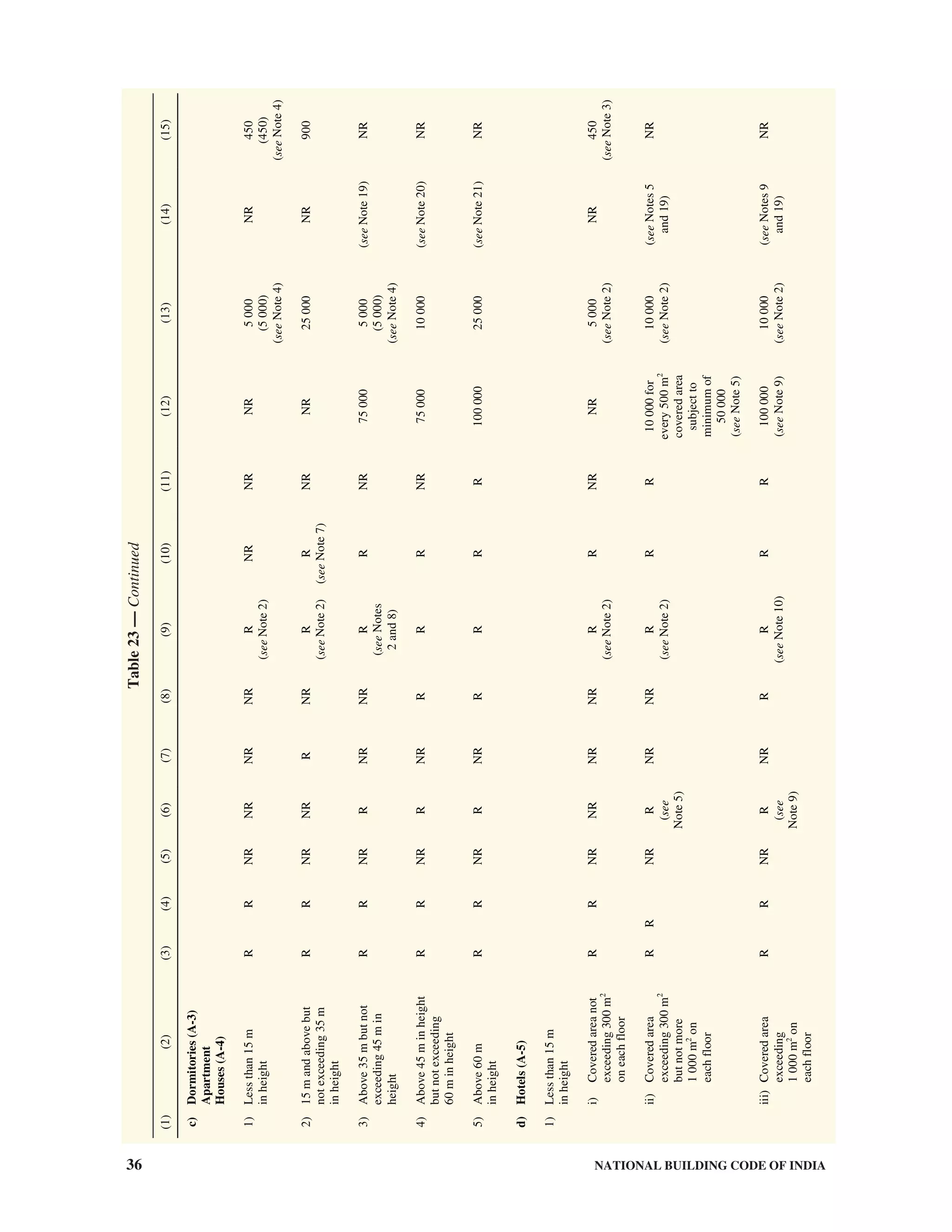
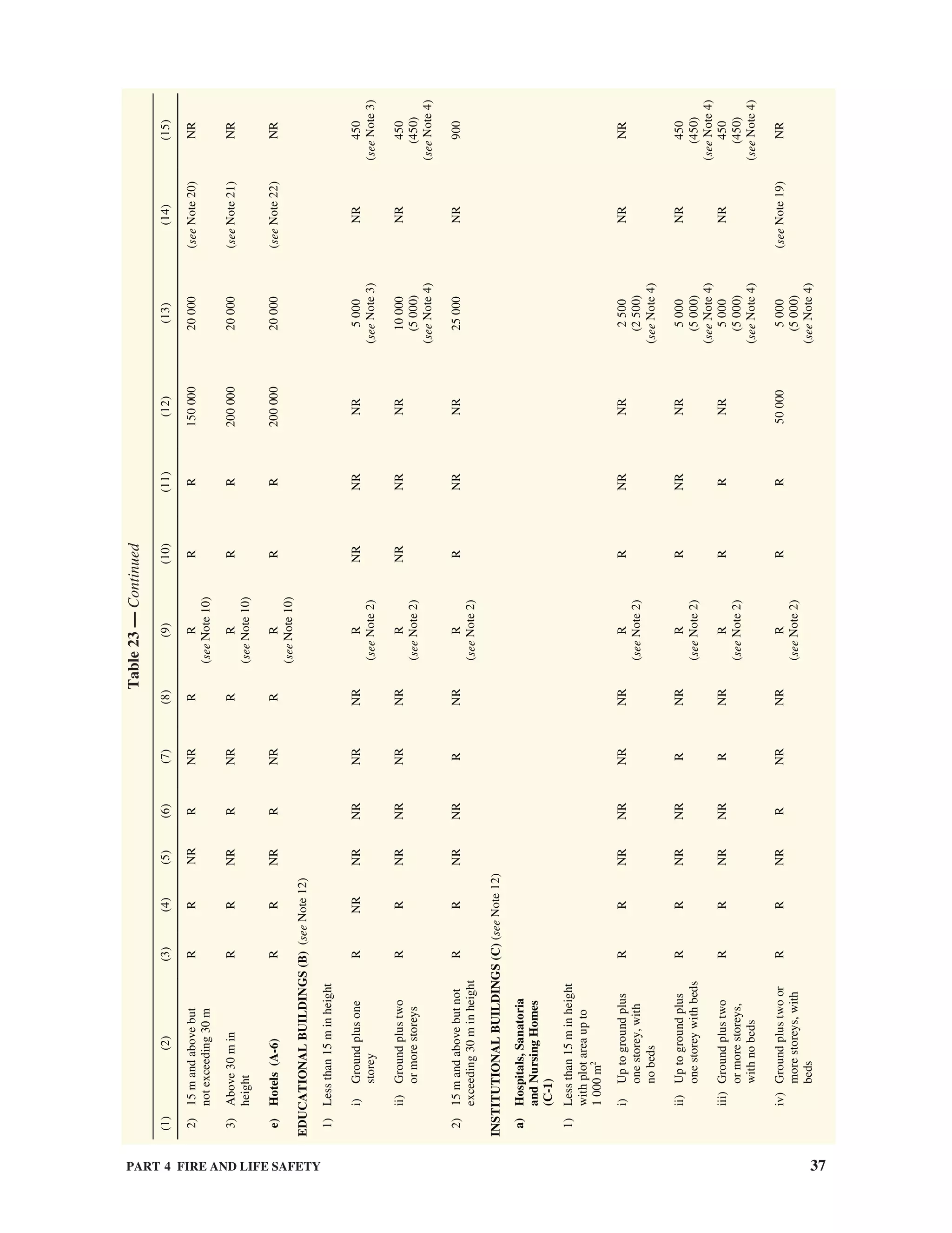
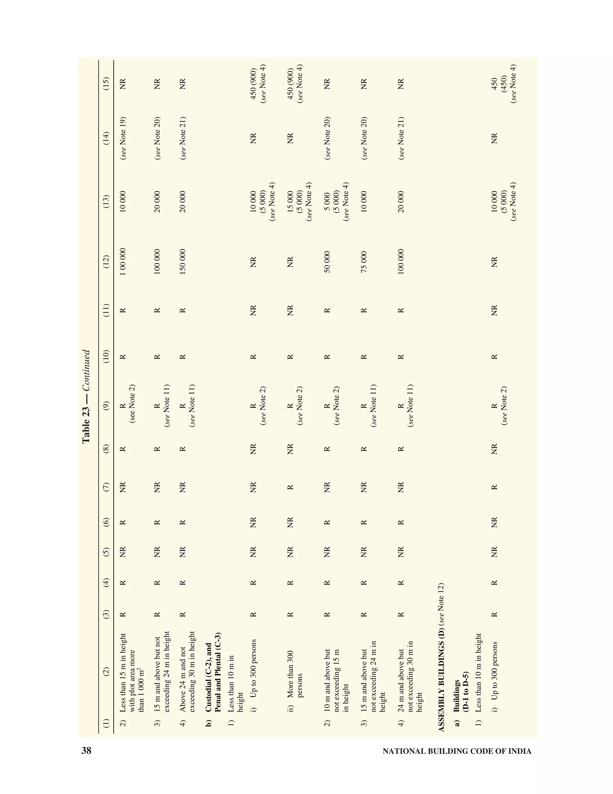

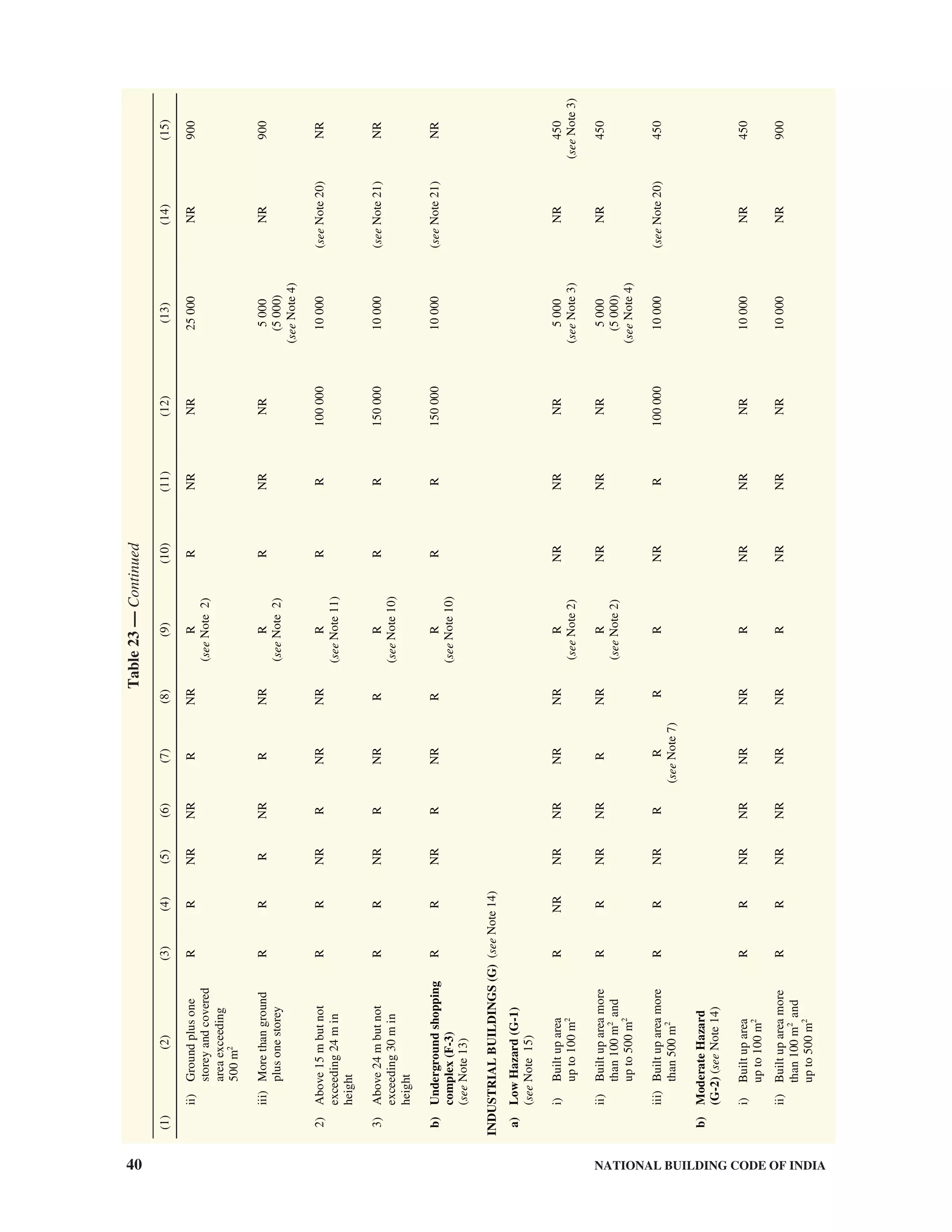
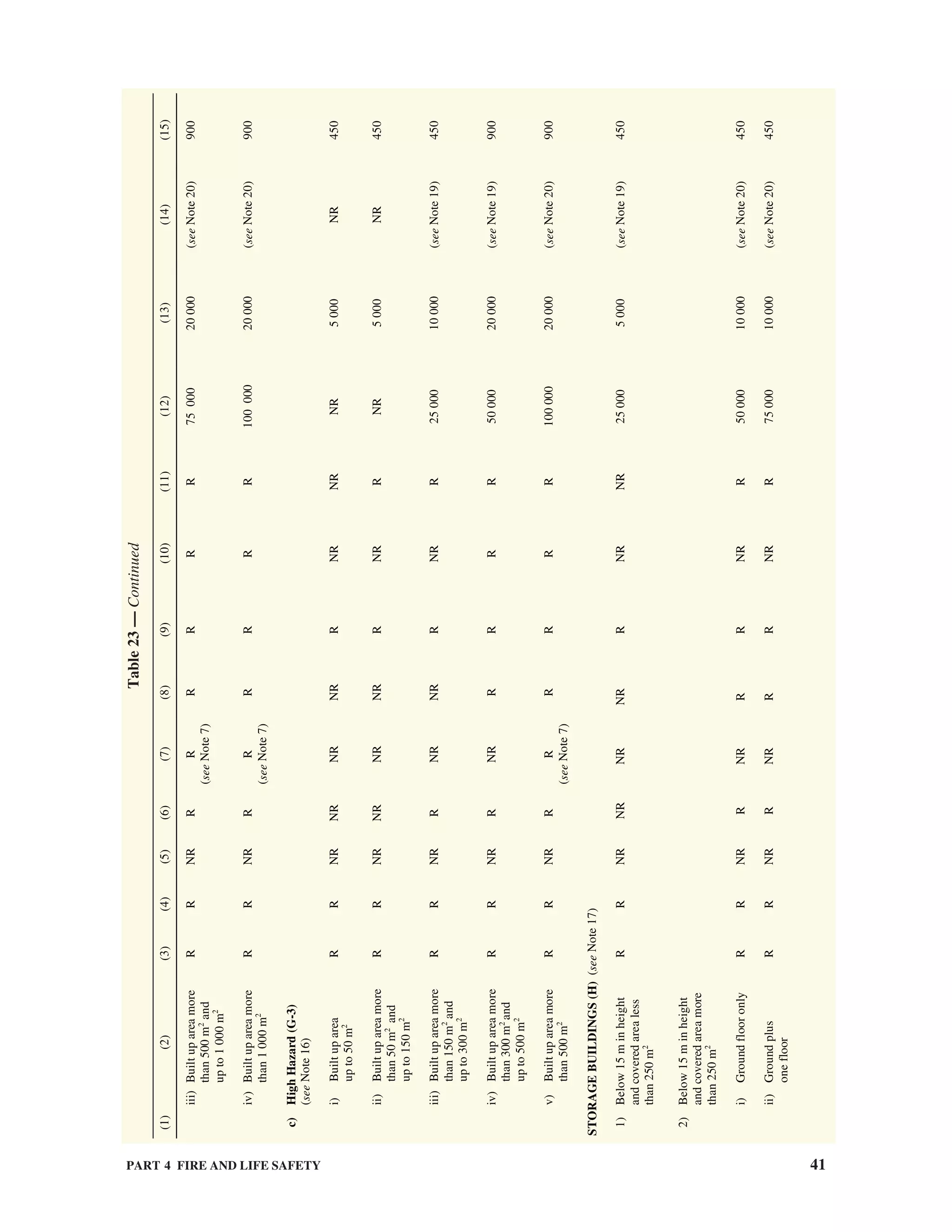
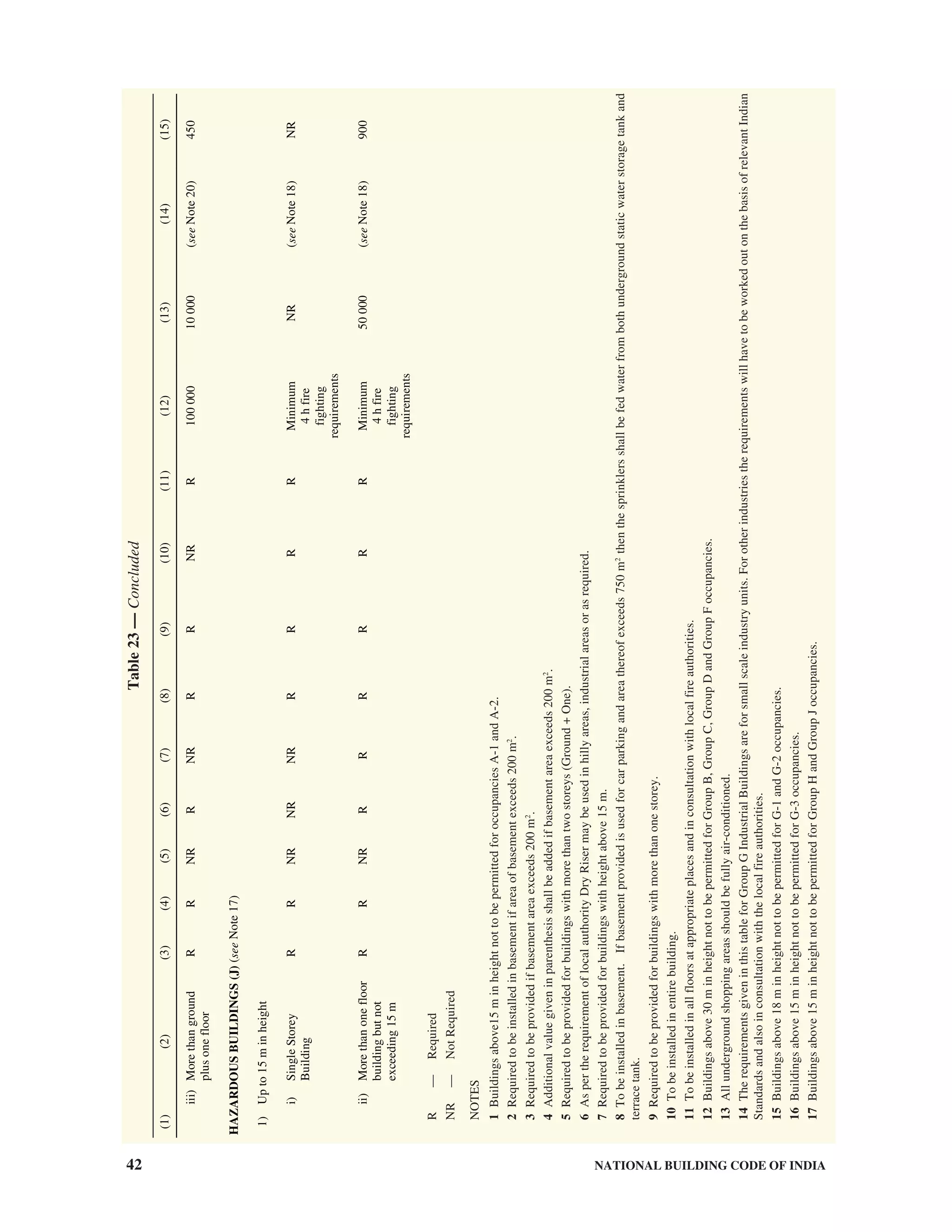
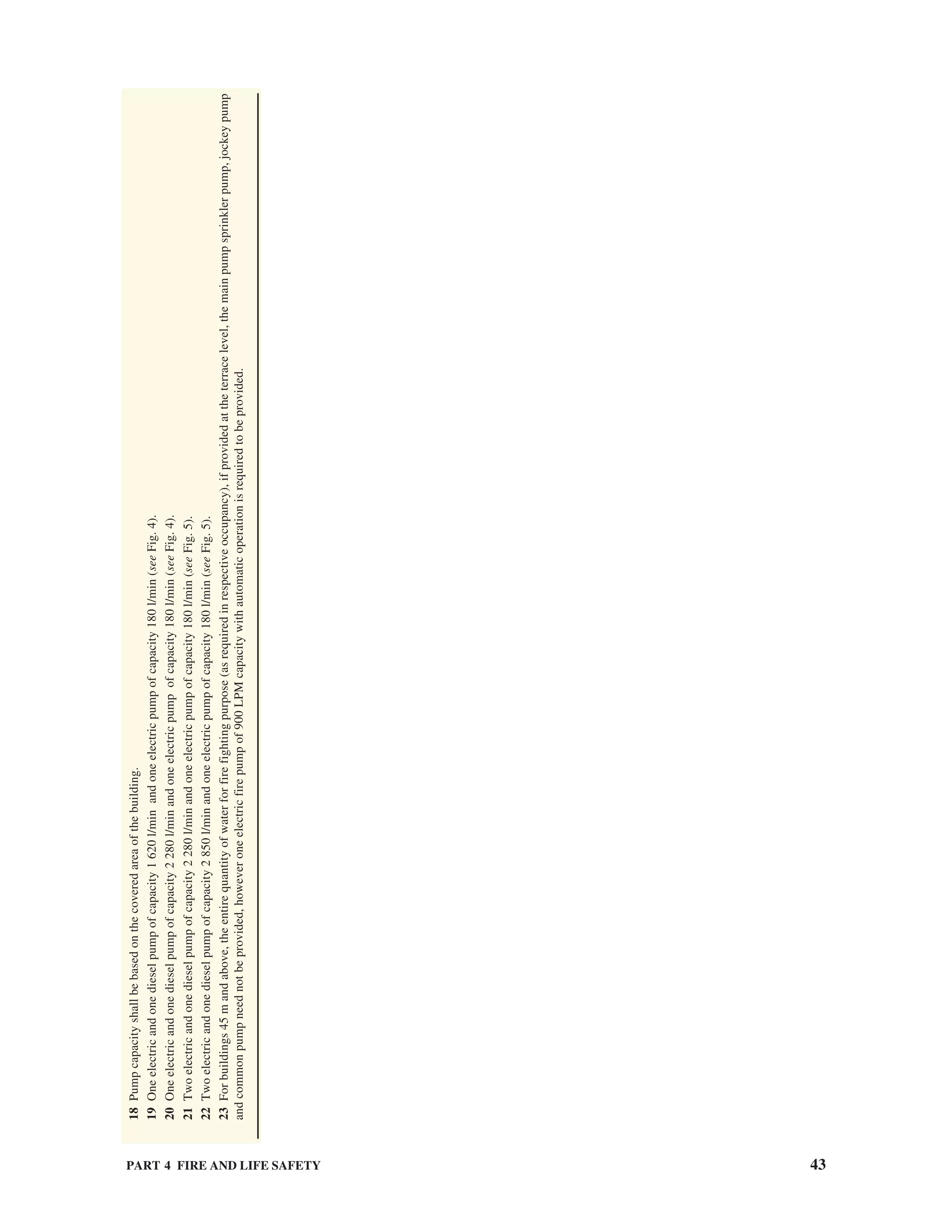
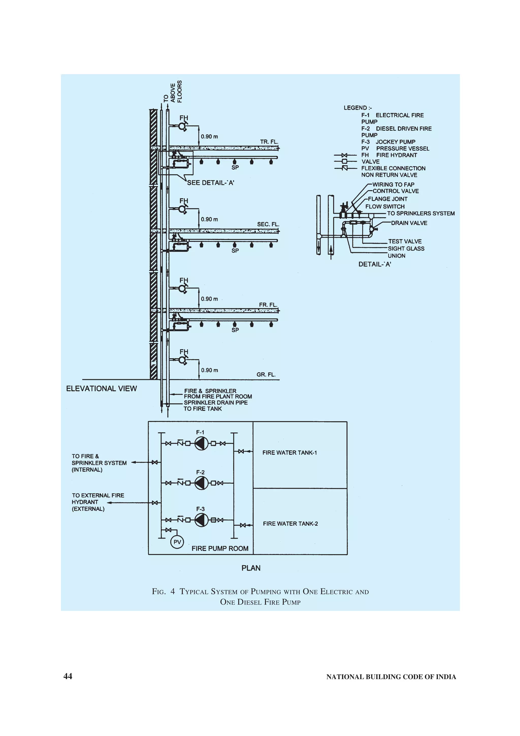
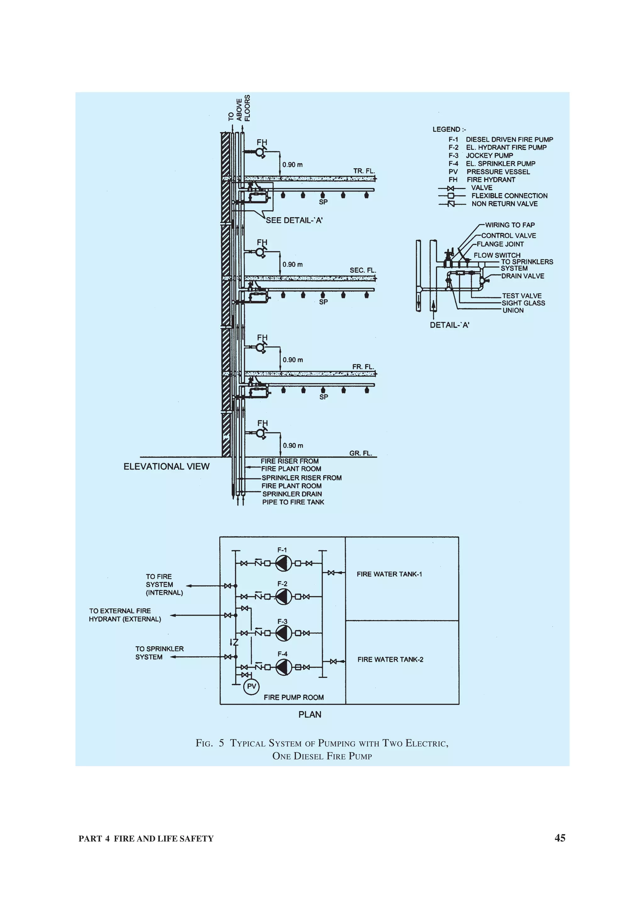
![46 NATIONAL BUILDING CODE OF INDIA
5.1.3 In situations where one occupancy is provided
with all the required fire protection arrangements but
due to proximity of unprotected buildings around,
causing exposure hazard to the protected building, the
protected building walls facing the unprotected
building shall be made of the requisite fire resistance
rated materials or alternatively provided with water
curtain/drencher system which can be actuated, when
necessary.
5.1.4 First-aid fire fighting appliances shall be
provided and installed in accordance with good practice
[4(21)]. The fire fighting equipment and accessories
to be installed in buildings for use in fire fighting shall
be in accordance with the accepted standards contained
in [4(20)] and shall be maintained periodically so as
to ensure their perfect serviceability at all times.
5.1.5 In addition to wet riser or down-comer, first-aid
hose reels shall be installed on all the floors of buildings
of 15 m in height or more and shall be in accordance
with accepted standards [4(22)]. The first-aid hose reel
shall be connected directly to the riser/down-comer
main and diameter of the hose reel shall not be less
than 19 mm.
5.1.6 Static Water Storage Tanks
A satisfactory supply of water for the purpose of fire
fighting shall always be available in the form of
underground/terrace level static storage tank with
capacity specified for each building with arrangements
or replenishment by mains of alternative source of
supply at the rate of 1 000 l/min for underground static
tank. When this is not practicable, the capacity of static
storage tank(s) shall be increased proportionately in
consultation with the local fire brigade.
The static storage water supply required for the above
mentioned purpose shall entirely be accessible to the
fire engines of the local fire service. Provision of
suitable number of manholes shall be made available
for inspection, repairs, insertion of suction hose,
etc. The covering slab shall be able to withstand the
total vehicular load of 45 T equally divided as a four
point load when the slab forms a part of pathway/
driveway.
The domestic suction tank connected to the static water
storage tank shall have an overflow capable of
discharging 2 250 l/min to a visible drain point from
which by a separate conduit, the overflow shall be
conveyed to a storm water drain.
a) To prevent stagnation of water in the static
water storage tank, the suction tank of the
domestic water supply shall be fed only
through an overflow arrangement to maintain
the level therein at the minimum specified
capacity (see Fig. 6).
b) The static water storage tank shall be provided
with a fire brigade collecting head with 4
number 63 mm diameter (2 number 63 mm
diameter for pump with capacity 1 400 l/min)
instantaneous male inlets arranged in a valve
box at a suitable point at street level and
connected to the static tank by a suitable fixed
pipe not less than 150 mm in diameter to
discharge water into the tank when required
at the rate of 2 250 l/min, if tank is in the
basement or not approachable for the fire
engines.
5.1.7 Automatic Sprinklers
Automatic sprinklers shall be installed in:
a) basements used as car parks or storage
occupancy, if the area exceeds 200 m2
;
b) multi-level basements, covered upper floors
used as car parks, and for housing essential
services ancillary to a particular occupancy
or for storage occupancy, excluding any area
to be used for sub-station, A.C. plant and DG
set;
c) any room or other compartment of a building
exceeding 1 125 m2
in area except as in (g)
(see Note 1), if so advised by local authority;
d) departmental stores or shops, if the aggregate
covered area exceeds 500 m2
;
e) all non-domestic floors of mixed occupancy
which constitute a hazard and are not provided
with staircases independent of the remainder
of the buildings;
f) godowns and warehouses, as considered
necessary;
g) on all floors of the buildings other than
residential and educational buildings, if the
height of the building exceeds 15 m (45 m in
case of group housing and apartments) (see
Note 1);
h) dressing room, scenery docks, stages and
stage basements of theatres;
j) in hotels, hospitals, industries low and
moderate hazard mercantile buildings of
height 15 m or above;
k) in hotels below 15 m, if covered area at each
floor is more than 1 000 m2
;
m) false ceiling voids exceeding 800 mm in
height (see Note 2); and
n) canteen provided in upper floors of D-1
and D-2 occupancies shall be sprinklered.
NOTES
1 It is desirable that all high rise buildings should be fully
sprinklered irrespective of their height and occupancy. If](https://image.slidesharecdn.com/is-200203030013/75/NATIONAL-BUILDING-CODE-SP7-158-2048.jpg)
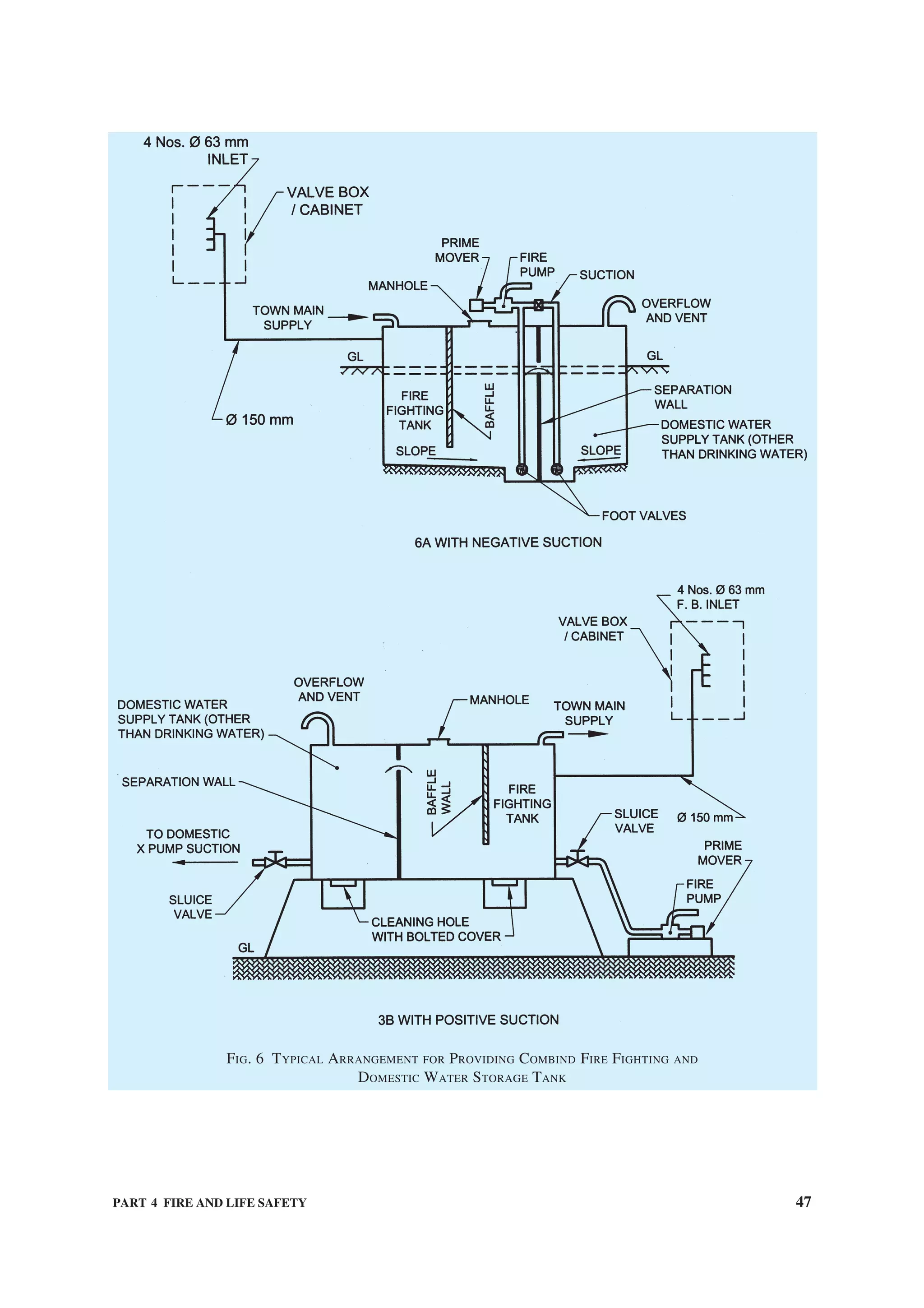
![48 NATIONAL BUILDING CODE OF INDIA
selective sprinklering is adopted, there is a real danger of a fire
starting on one of the lower unsprinklered floors gathering
momentum, spreading upwards from floor to floor through the
unsprinklered floor and reaching the first sprinklered floor as
a fully developed fire. In such an event, the sprinklers can be
rendered useless or ineffective.
2 Use of false ceiling voids for storage or as return air plenums
should be discouraged.
3 For areas having very high ceiling height and other special
function areas, where automatic sprinklers cannot be provided,
appropriate sprinklers/provisions shall be provided in
consultation with local fire authorities.
5.1.8 Automatic High Velocity Water Spray or
Emulsifying System
Automatic high velocity water spray or emulsifying
system shall be provided for protection of indoor oil-
cooled transformers as applicable in accordance
with C-1.16 and good practice [4(23)].
5.1.9 Fixed Foam Installation
Fixed foam generating system shall be provided for
protection of oil storage area for boilers with its
ancillary storage of furnace oils in basement. Fixed
foam installations can be low, medium or high
expansion types, which can cover fire risks in oil
storage areas generally. High expansion foams are used
for cable tunnels and other confined areas.
5.1.10 Carbon Dioxide Fire Extinguishing System
Fixed carbon dioxide fire extinguishing installation
shall be provided in accordance with good practice
Table 24 Size of Rising Mains/Risers
(Clause 5.1.2)
Size of the Mains Type of Building Height of Building
(1) (2) (3)
100 mm as single outlet
landing valves
1. Residential buildings (A)
i) 1)
Lodging or rooming houses
ii) Dormitories
iii) One or two family private dwellings
iv) Apartment houses (flats)
v) With shopping area not exceeding
500 m2
vi) Hotels
15 m or above and not exceeding 45 m
Less than 15 m
15 m or above in height but not exceeding 30 m
and area not exceeding 600 m2
per floor
-do- 2. Educational buildings (B) 15 m or above but not exceeding 30 m
-do- 3. Institutional buildings (C)
i) For hospitals and sanitorium
ii) For custodial institutions and mental
institutions
15 m or above but not exceeding 30 m
15 m or above but not exceeding 30 m
-do- 4. Assembly buildings (D) 15 m or above but not exceeding 30 m and total floor
area not exceeding 500 m2
/floor (above 30 m, not to
be permitted)
-do- 5. Business buildings (E) 15 m or above but not exceeding 30 m
-do- 6. Mercantile buildings (F) 15 m or above but not exceeding 30 m
(above 30 m, not to be permitted)
-do- 7. Industrial buildings (G) 15 m or above but not exceeding 18 m
-do- 8. All buildings classified under 1 (i) to (iv) Above 45 m
-do- 9. All buildings classified under 5 above with
shopping area exceeding 500 m2
Above 15 m
-do- 10. All buildings classified under 1 (v) above Above 30 m and area exceeding 500 m2
150 mm with twin outlet
landing valves
11. Hotels Above 30 m
-do- 12. All buildings classified under 2 and 3 above Above 30 m
-do- 13. All buildings classified under 5 above Above 30 m
-do- 14. All storage buildings (H) Above 10 m but not exceeding 15 m
-do- 15. All Hazardous buildings (J) Above 10 m but not exceeding 15 m
—————————————————
1)
Buildings above 15 m in height not permitted in case of high hazard industrial buildings.](https://image.slidesharecdn.com/is-200203030013/75/NATIONAL-BUILDING-CODE-SP7-160-2048.jpg)
![PART 4 FIRE AND LIFE SAFETY 49
[4(24)] on premises where water or foam cannot be
used for fire extinguishing because of the special nature
of the contents of the buildings/areas to be protected.
For some special fire risk/essential applications, carbon
dioxide may not be suitable and it may be necessary to
provide BCF (Bromochlorodifluoromethane) — Halon
1211 or BTM (Bromochlorotrifluoromethane) —
Halon 1301 or some other identified substitutes.
However, the use of halons shall be discouraged, as
halons are ozone depleting substances (ODS) and their
use is being phased out throughout the world.
5.1.11 Fire fighting equipment shall be suitably
located and clearly marked by luminous signs.
NOTE — This provision shall not apply to occupancies A-2
and A-4 less than 15 m in height.
5.2 Fire Detection/Extinguishing System
In buildings of such size, arrangement or occupancy
that a fire may not itself provide adequate warning to
occupants, automatic fire detection and alarm facilities
shall be provided, where necessary, to warn occupants
early of the existence of fire, so that they may escape,
or to facilitate the orderly conduct of fire exit drills.
5.2.1 The fire detection and extinguishing system shall
be in accordance with accepted standards [4(18)].
Guidelines for selection of various types of fire
detectors for different occupancies shall be in
accordance with good practice [4(19)]. Addressable
analog fire detection system shall be preferred.
5.2.2 The requirements of fire detection and alarm
systems are also covered for each occupancy in 6.1
to 6.9; and for high rise buildings (15 m or more in
height) in Annex C.
5.3 Fire Extinguisher/Extinguishing System Using
Halon Alternatives
Provisionsforcertainfireextinguishersandextinguishing
systems for fire protection which may be used as halon
alternatives, shall be in accordance in [4(25)].
6 ADDITIONAL OCCUPANCY-WISE
REQUIREMENTS
6.1 RequirementsofResidentialBuildings(GroupA)
6.1.1 In addition to the general requirements for the
type of construction and occupancy group specified
in 3.4 and the exit requirements given in 4, the
requirements 6.1.2 to 6.1.4.10 shall be complied with.
The capacity of any open mezzanine or balcony shall
be added to the capacity of the floor below for the
purpose of determining exit capacity.
6.1.2 Fire Detection/Extinguishing System
The requirements for occupancy sub-divisions A-1 to
A-5 as specified in Table 23 and Annex C (for High
Rise Buildings) shall apply.
6.1.3 Exit Facilities
The capacity of any open mezzanine or balcony shall
be added to the capacity of the floor for the purpose of
determining the exit capacity.
6.1.3.1 In addition to requirements specified for
occupancy sub-division A-2, the following shall be
provided for occupancy sub-division A-1:
Every sleeping room above the street floor shall
have access to two separate means of exits, at least
one of which shall consist of an enclosed interior
stairway, or a fire escape or horizontal exit all so
arranged as to provide a safe path of travel to the
outside of the building without traversing any
corridor or space exposed to an unprotected
vertical opening.
6.1.3.2 For occupancy sub-division A-2 of more than
two rooms, every occupied room, excluding areas used
solely for storage shall have at least two means of exits,
at least one of which shall be a door or a stairway
providing a means of un-obstructed travel to the outside
of the building or street or grade level. No room or
space shall be occupied which is accessible only by a
ladder, folding stairs or through a trap door.
Further the following provisions shall be made:
All locking devices, which would impede or
prohibit exit, such as chain type bolts, limited
opening sliding type locks and burglar locks,
which are not dis-engaged easily by quick-
releasing catches, shall be prohibited. All closet
door latches shall be such that even children can
open the doors from inside. All bathroom door
locks or fasteners shall be designed to permit the
opening of the locked or closed door from the
outside in an emergency without the use of a
special key.
6.1.3.3 For occupancy sub-division A-3, the following
provisions shall apply:
All dormitories shall have exits so arranged that
from any sleeping room or open dormitory
sleeping area, there shall be access to two separate
and distinct exits in different directions with no
common path of travel unless the room or space
is subject to occupancy by not more than 10
persons and has a door opening directly to the
outside of the building at street or grade level, or
to an outside stairway in which case one means of
exit may be accepted.
6.1.3.4 For occupancy sub-division A-4, the following
provisions shall apply:](https://image.slidesharecdn.com/is-200203030013/75/NATIONAL-BUILDING-CODE-SP7-161-2048.jpg)
![50 NATIONAL BUILDING CODE OF INDIA
a) Every individual living unit covered by
occupancy sub-division A-4 shall comply
with the requirement for occupancy sub-
division A-2in respect of exits.
b) Every living unit shall have access to at least
two separate exits, which are remote from
each other and are reached by travel in
different directions, except that a common
path of travel may be permitted for the first
6 m (that is a dead end corridor up to 6 m long
may be permitted) provided that single exit
may be permitted under any of the conditions
given under (c).
c) Any part of building lower than the grade
level shall have direct accessibility from
outside.
d) At least half of required exits shall discharge
direct to the outside of the buildings; any
other exit shall be the same as required for
hotels.
6.1.3.5 For occupancy sub-divisions A-5 and A-6, the
following provisions shall apply:
a) Not less than two exits, as remote from each
other as practicable, shall be accessible from
every floor, including basements occupied for
hotel purpose, except as a single exit as
permitted in (b) below. Exits and ways of
access thereto shall be so arranged that they
are accessible in at least two different
directions from every point in any open area,
or from any room door.
b) Any room or section with an outside door at
street or grade level may have such outside
door as a single exit, provided no part of the
room or area is more than 15 m from the door
measured along the natural path of travel.
c) Provision of panic bars shall be provided in
the exits.
6.1.3.5.1 Where stairways or other exits serve two or
more upper floors, the same stairway or other exit
required to serve any one upper floor may also serve
other upper floors, except that no inside open stairway
or ramp may serve as a required egress facility from
more than one floor [see good practice 4(26)].
6.1.3.6 Basement Exits
a) Basements occupied for hotel purposes shall
have exits arranged in accordance with 6.1.3.5.
b) Basement exits shall be sufficient to provide
for the capacity of the basement as determined
in accordance with 6.1.1. In no case shall there
be less than two independent basement exits.
c) Basement or sub-basements not open to the
public and used only for heating equipment,
storage and service operations (other than
kitchens, which are considered part of the hotel
occupancy) shall have exits appropriate to the
actual occupancy, in accordance with other
applicable provisions of the Code, or in case
of mixed occupancy where there may be doubt
as to which other section is applicable, such
basements shall have exits determined on the
basis of lesser exit capacity.
6.1.4 Additional Precautions
6.1.4.1 Flammable liquids for household purposes
shall be kept in tightly stoppered or sealed containers.
For the limits of quantities of flammable liquids to be
allowed in various occupancies, reference may be made
to appropriate regulations.
6.1.4.2 No stove or combustion heater shall be located
directly under or immediately at the foot of stairs or
otherwise so located as to block escape in case of
malfunctioning of the stove or heater.
6.1.4.3 All kitchen exhaust fans, where provided, shall
be fixed to an outside wall or to a duct of non-
combustible material, which leads directly to the
outside. The ducts must not pass through areas having
combustible materials.
6.1.4.4 All wiring shall be done in accordance with
Part 8 ‘Building Services, Section 2 Electrical
Installations’, good practice [4(10)] and National
Electric Code.
6.1.4.5 Where television is installed, all outdoor
antennae shall be properly grounded and protected
from lightning (see Part 8 ‘Building Services, Section 2
Electrical Installations’).
6.1.4.6 Doors leading to rooms in which flammable
liquids are stored or used shall be as in 4.7. Such
assembly shall be self-closing and shall be posted with
a sign on each side of the door in 25 mm high block
letters stating — ‘FIREDOOR — KEEP CLOSED’.
6.1.4.7 Where a boiler room is provided or a central
heating plant is installed, which uses solid or liquid
fuel, it shall be separated from rest of the building by a
separation wall with all openings protected as in 3.4.7
and 3.4.8.
6.1.4.8 Rooms containing high pressure boilers,
refrigerating machinery, transformers or other service
equipment subject to possible explosion shall not be
located directly under or adjacent to exits. All such
rooms shall be effectively cut off from other parts of
the building and shall be provided with adequate vents
to the outside air.
6.1.4.9 All rooms or areas of high hazard in additions
to those herein before mentioned, shall be segregated](https://image.slidesharecdn.com/is-200203030013/75/NATIONAL-BUILDING-CODE-SP7-162-2048.jpg)
![52 NATIONAL BUILDING CODE OF INDIA
6.3.3.2 Not less than two exits of one or more of the
following types shall be provided for every floor,
including basement, of every building or section:
a) Doors leading directly outside the building;
b) Stairways;
c) Ramps;
d) Horizontal exits; and
e) Fire tower.
6.3.3.3 All required exits that serve as egress from
hospital or infirmary sections shall be not less than
2 m in clear width including patient bedroom doors to
permit transportation of patients on beds, litters, or
mattresses. The minimum width of corridors serving
patients bedrooms in buildings shall be 2 400 mm. For
detailed information on recommendations for buildings
and facilities for the physically handicapped, reference
may be made to good practice [4(27)].
6.3.3.4 Elevators constitute a desirable supplementary
facility, but are not counted as required exits. Patient
lifts shall also be provided with enough room for
transporting a stretcher trolley.
6.3.3.5 Any area exceeding 500 m2
shall be divided
into compartments by fire resistant walls.
6.3.3.6 Doors in fire resistant walls shall be so installed
that these may normally be kept in open position, but
will close automatically. Corridor door openings in
smoke barriers shall be not less than 2 000 mm in width.
Provision shall also be made for double swing single/
double leaf type door.
6.3.3.7 Exits and other features for penal and mental
institutions, and custodial institutions shall be the same
as specified for hospitals, in so far as applicable.
Reliable means shall be provided to permit the prompt
release of inmates from any locked section in case of
fire or other emergency.
6.3.3.8 Whereveranyinmatesareconfinedinanylocked
rooms or spaces, adequate guards or other personnel shall
be continuously on duty or immediately available to
provide for release of inmates or for such other action as
may be indicated in case of fire or other emergency.
6.3.3.9 No building constructed in whole or in part of
combustible materials shall be used to confine inmates
in cells or sleeping quarters, unless automatic sprinkler
protection is provided.
6.3.3.10 All buildings or sections of buildings in penal
and mental institutions used for manufacturing, storage
or office purposes shall have exits in accordance with
the provisions of the Code for those occupancies.
6.3.4 Additional Precautions
6.3.4.1 No combustible material of any kind shall be
stored or used in any building or section thereof used
for institutional occupancy, except as necessary to
normal occupancy and use of the building.
6.3.4.2 Bare minimum quantities of flammable
material such as chloroform, ethyl alcohol, spirit, etc
shall be allowed to be stored and handled. The handling
of such liquids shall not be permitted by un-authorized
persons. Bulk storage of these items, will be governed
by relevant rules and safe practices.
6.3.5 Exceptions and Deviations
It is recognized that in institutions or part of buildings
housing various types of psychiatric patients, or used
as penal and mental institutions, it is necessary to
maintain locked doors and barred windows; and to such
extent the necessary provision in other sections of the
Code requiring the keeping of exits unlocked may be
waived. It is also recognized that certain type of
psychiatric patients are not capable of seeking safety
without adequate guidance. In buildings where this
situation prevails, reliable means for the rapid release
of occupants shall be provided, such as remote control
of locks, or by keying all locks to keys commonly used
by attendants.
6.4 Requirements of Assembly Buildings (Group D)
6.4.1 In addition to the general requirements specified
in 3.4 for type of construction and occupancy group
and the exit requirements given in 4, the requirements
given in 6.4.2 to 6.4.8.9 shall be complied with.
6.4.2 Mixed Occupancy
Places of assembly in buildings of other occupancy,
such as ballrooms in hotels, restaurants in stores and
assembly rooms in schools, shall be so located,
separated or protected as to avoid any undue danger to
the occupants of the place of assembly from a fire
originating in the other occupancy or smoke therefrom.
6.4.3 Fire Detection/Extinguishing System
The requirements for occupancy sub-divisions D-1 to
D-5 as specified in Table 23 and Annex C (for High
Rise Buildings) shall apply.
NOTE — Canteens shall not be provided in basements. If
provided in the upper floors, it shall be sprinklered.
6.4.4 Exit Facilities
6.4.4.1 Every place of assembly, every tier or balcony,
and every individual room used as a place of assembly
shall have exits sufficient to provide for the total
capacity thereof as determined in accordance with 4.
Door width for assembly buildings shall not be less
than 2 000 mm.
a) Every place of assembly of sub-division D-1](https://image.slidesharecdn.com/is-200203030013/75/NATIONAL-BUILDING-CODE-SP7-164-2048.jpg)
![PART 4 FIRE AND LIFE SAFETY 53
shall have at least four separate exits as remote
from each other as practicable.
b) Every place of assembly of sub-division
D-2, shall have at least two separate exits as
remote from each other as practicable and if
of capacity over 600 at least three exits shall
be provided with each exit not less than of
2 000 mm width.
6.4.4.2 Clear aisles not less than 1.2 m in width shall
be formed at right angles to the line of seating in such
number and manner that no seat shall be more than seven
seats away from an aisle. Rows of seats opening on to
an aisle at one end only shall have not more than seven
seats. Under the conditions, where all these aisles do
not directly meet the exit doors, cross-aisles shall be
provided parallel to the line of seating so as to provide
direct access to the exit, provided that not less than one
cross aisle for every 10 rows shall be required. The width
of cross-aisles shall be minimum of 1 m. Steps shall not
be placed in aisles to overcome differences in levels,
unless the gradient exceeds 1 in 10.
6.4.4.3 The fascia of boxes, balconies and galleries
shall have substantial railings not less than 1 000 mm
high above the floor. The railings at the end of aisles
extending to the fascia shall be not less than 1 100 mm
high for the width of the aisle or 1 200 mm high at the
foot of steps.
6.4.4.4 Cross-aisles except where the backs of seats
on the front of the aisle project 600 mm or more above
the floor of the aisle shall be provided with railings
not less than 900 mm high.
6.4.4.5 No turnstiles or other devices to restrict the
movement of persons shall be installed in any place of
assembly in such a manner as to interfere in any way
with the required exit facilities.
6.4.4.6 In theatres and similar places of public
assembly where persons are admitted to the building
at a time when seats are not available for them and are
allowed to wait in a lobby or similar space until seats
are available, such use of lobby or similar space shall
not encroach upon the required clear width of exits.
Such waiting shall be restricted to areas separated from
the required exit ways by substantial permanent
partitions or fixed rigid railing not less than 105 cm
high. Exits shall be provided for such waiting spaces
on the basis of one person for each 0.3 m2
of waiting
space area. Such exits shall be in addition to the exits
specified for the main auditorium area and shall
conform in construction and arrangement to the general
rules of exits given above.
6.4.4.7 No display or exhibit shall be so installed or
operated as to interfere in any way with access to any
required exit, or with any required exit sign.
All displays or exhibits of combustible material or
construction and all booths and temporary construction
in connection therewith shall be so limited in
combustibility or protected as to avoid any undue
hazard of fire which might endanger occupants before
they have opportunity to use the available exits, as
determined by the authority.
6.4.4.8 Places of assembly in buildings of other
occupancy may use exits common to the place of
assembly and the other occupancy, provided the
assembly area and the other occupancy are considered
separately, and each has exits sufficient to meet the
requirements of the Code.
6.4.4.9 Exits shall be sufficient for simultaneous
occupancy of both the places of assembly and other
parts of the building, unless the Authority determines
that the conditions are such that simultaneous
occupancy will not occur.
6.4.4.10 For any place of assembly under sub-division
D-1, at least half the required means of exits shall lead
directly outdoors or through exit ways completely
separated from exits serving other parts of the building.
6.4.4.11 For detailed information regarding cinema
buildings, reference may be made to good practice
[4(28)].
6.4.5 Lighting
No open flame lighting devices shall be used in any
place of assembly, except in the following cases:
a) Where necessary for ceremonial purposes, the
enforcing Authority may permit open flame
lighting under such restrictions as are
necessary to avoid danger of ignition of
combustible materials or injury to occupants.
b) Candles may be used on restaurant tables if
securely supported on non-combustible bases
and so located as to avoid danger of ignition
of combustible materials.
c) Open flame devices may be used on stages
where they are a necessary part of theatrical
performance, provided adequate precautions,
satisfactory to the Authority are taken to
prevent ignition of combustible materials.
6.4.6 Additional Precautions
6.4.6.1 The decorations of places of assembly shall
be of non-flammable materials. Fabrics and papers used
for such purpose shall be treated with an effective
flame-retardant material. Stage settings made of
combustible materials shall likewise be treated with
fire retardant materials of Class 1 flame spread.
6.4.6.2 Seats in places of public assembly,
accommodating more than 300 persons, shall be](https://image.slidesharecdn.com/is-200203030013/75/NATIONAL-BUILDING-CODE-SP7-165-2048.jpg)
![54 NATIONAL BUILDING CODE OF INDIA
securely fastened to the floor, except as permitted
in 6.4.6.3. All seats in balconies and galleries shall be
securely fastened to the floor, except that in nailed-in
enclosures, boxes with level floors and having not more
than 14 seats, the seats need not be fastened.
6.4.6.3 Chairs not secured to the floor may be
permitted in restaurants, night clubs and other
occupancies where the fastening of seats to the floor
may not be practicable, provided that in the area used
for seating, excluding dance floor, stage, etc, there shall
be not more than one seat for each 1.4 m2
of floor area
and adequate aisles to reach exits shall be maintained
at all times.
6.4.6.3.1 Rows of seats between aisles shall have not
more than 14 seats.
6.4.6.3.2 Rows of seats opening on to an aisle at one
end only shall have not more than 7 seats.
6.4.6.3.3 Seats without dividing arms shall have their
capacity determined by allowing 450 mm per person.
6.4.6.4 The spacing of rows of seats from back-to-
back shall be neither less than 850 mm nor less than
700 mm plus the sum of the thickness of the back and
inclination of the back. There shall be a space of not
less than 350 mm between the back of one seat and
the front of the seat immediately behind it as measured
between plumb lines.
6.4.6.5 Rooms containing high pressure boilers,
refrigerating machinery other than domestic
refrigerator type, large transformers or other service
equipments subject to possible explosion shall not be
located directly under or adjacent to the required exits.
All such rooms shall be effectively cut off from other
parts of the building and provided with adequate vents
to the outer air.
6.4.6.6 All rooms or areas used for storage of any
combustible materials or equipment, or for painting,
refinishing, repair or similar purposes shall be
effectively cut off from assembly areas or protected
with a standard system of automatic sprinklers. They
shall be located away from staircases.
6.4.6.7 Every stage equipped with fly galleries, grid
irons and rigging for movable theatre type scenery,
shall have a system of automatic sprinklers over and
under such stage areas or spaces and auxiliary spaces,
such as dressing rooms, store rooms and workshops,
and the proscenium opening shall be provided with a
fire- resisting curtain, capable of withstanding a lateral
pressure of 4 kN/m2
over the entire area. The curtain
shall have an emergency closing device capable of
causing the curtain to close without the use of power
and when so closed, it shall be reasonably tight against
the passage of smoke.
6.4.6.8 The stage roof of every theatre using movable
scenery or having a motion picture screen of highly
combustible construction shall have a ventilator or
ventilators in or above it, openable from the stage floor
by hand and also opening by fusible links or some other
approved automatic heat/smoke actuated device, to
give a free opening equal to at least one-eighth the
area of the floor of the stage.
6.4.6.9 The proscenium wall of every theatre using
movable scenery of decorations shall have, exclusive
of the proscenium opening, not more than two openings
entering the stage, each not to exceed 2 m2
and fitted
with self-closing fire resistant doors.
6.4.6.10 Every place of assembly in which projection
of motion pictures by light is made shall have the
projection apparatus enclosed in a fire-resisting fixed
booth in accordance with good practice [4(27)], except
that such booth shall not be required where no
nitrocellulose motion picture film is used.
6.4.6.11 Automatic smoke vents actuated by smoke
detectors shall be installed above the auditorium or
theatres, including motion picture houses, with vent
area equal to not less than 3 percent of the floor area
of the auditorium, including the sum of the floor areas
of all balconies, galleries, boxes and tiers. It may be
desirable to provide a large number of small vents
rather than a small number of large vents.
6.4.7 Exception and Deviation
6.4.7.1 Where boilers or central heating plants using
liquid or solid fuel are located at grade level, these
shall be separated from the remainder of the building
by a separating wall with openings protected as in 3.4.7
and 3.4.8.
6.4.7.2 Gymnasiums, indoor stadiums and similar
occupancies may have floors/running tracks of wood,
cinder, synthetic or un-protected steel or iron.
6.4.7.3 The underside of continuous steel deck grand
stands when erected outdoors need not be fire-protected
when occupied for public toilets.
6.4.8 Fire Protection and Fire Fighting System for
Metro Stations
6.4.8.1 Wet riser system
Main and diesel fire pump of 1 800 l/min capacity to
be provided to support 3 to 4 hydrants at a time. Jockey
pump capacity shall be 180 l/min. Where it is possible
to extend reliable DG supply to the fire pump room
without routing through the station building, the
provision of diesel pump can be dispensed with and
instead, two electric pumps may be provided out of
which at least one should have DG back-up. The jockey
pump should also have DG back-up.](https://image.slidesharecdn.com/is-200203030013/75/NATIONAL-BUILDING-CODE-SP7-166-2048.jpg)
![56 NATIONAL BUILDING CODE OF INDIA
6.5 Business Buildings (Group E)
6.5.1 In addition to the general requirements specified
in 3.4 for type of construction and occupancy group
and the exit requirements given in 4, the requirements
given in 6.5.2 to 6.5.5 shall be complied with.
6.5.2 Fire Detection/Extinguishing System
The requirements for occupancy sub-divisions as
specified in Table 23 and Annex C (for High Rise
Buildings) shall apply.
6.5.2.1 Occupancy sub-division E-1 (except office
buildings)
Details of
Occupancy
Fire Detection/Extinguishing
System
E-1 Automatic fire alarm system {good
practice [4(17)] and [4(18)], and
Table 23}.
They shall be provided in various areas as detailed hereunder:
Sl
No.
Item Numbers and Location
(1) (2) (3)
PLATFORM
1. Internal Hydrants Two at each platform. The hydrants at two platforms may be
staggered for maximum coverage.
2. Manual call box One on each platform preferably near emergency plunger.
3. Portable Extinguishers One set of Water CO2 and CO2 type on each platform at a central
area.
CONCOURSE
1. Internal Hydrants Two at each concourse. When concourse is in two parts then each
part should have at least one hydrant.
2. Additional first-aid reel point Additional first-aid reel point for every additional 1 000 m2
, if the
area is more than 2 000 m2
. Similarly, if the concourse is in two parts
then additional first aid reel point for every additional
1 000 m2
, if the area of the part is more than 1 000 m2
.
3. Manual call box Two at each concourse. When concourse is in two parts then each
part should have at least one.
4. Portable Extinguishers Two sets at each concourse. When concourse is in two parts then
each part should have at least one set.
5. Detectors Above false ceiling where depth of false ceiling is greater than
800 mm. Required in commercial areas also.
EQUIPMENT ROOM AREAS
1. Internal Hydrants/first-aid reel
point
The requirement shall get covered with platform/concourse.
Additional first-aid reel point may be provided, if required.
2. Manual call box One at a central place. When the equipment rooms are in two/more
parts then each part should have one.
3. Portable Extinguishers One set for each room.
4. Detectors Above and below false ceiling and below floor giving due
consideration to depth of false ceiling/floor.
5. Response Indicator To be provided.
6. Panel gas flooding To be provided for HT panel, main LT panel, main LT distribution
board and essential power panels and other such major panels.
EXTERNAL AREAS
1. Hydrants One at ground floor at each entry to station near staircase/DG room.
2. Two/four way fire brigade inlet To be provided for each riser/sprinkler riser.
3. Fire brigade Draw-off connection To be provided on water tank.](https://image.slidesharecdn.com/is-200203030013/75/NATIONAL-BUILDING-CODE-SP7-168-2048.jpg)
![PART 4 FIRE AND LIFE SAFETY 57
6.5.2.2 Occupancy sub-division E-2
Details of
Occupancy
Fire Detection/Extinguishing
System
a) Laboratory
with delicate
instruments
Fixed automatic CO2 fire
extinguishing system or
automatic fire alarm system
{good practice [4(18)] and
[4(19)], and Table 23}
b) Solvent storage
and/or flammable
liquid
Automatic foam installation
or automatic CO2 fire
extinguishing system
6.5.2.3 Occupancy sub-division E-3
Details of
Occupancy
Fire Detection/Extinguishing
System
a) Area of computer
installations
Automatic fire alarm system
{good practice [4(18)] and
[4(19)], and Table 23} any
suitable halon alternative fire
extinguishing system (see
5.3) or any other suitable fire
extinguishing installation
{see also [4(29)]}.
b) Space under false
ceiling (floor)
Automatic fire alarm system
{good practice [4(18)] and
[4(19)], and Table 23}
c) Space above false
ceiling and below
false floor
Automatic fire alarm system
{good practice [4(18)] and
[4(19)], and Table 23}
d) Electrical switch
board
Automatic fire alarm system
{good practice [4(18)] and
[4(19)], and Table 23} and
CO2 fire extinguishing
installation
6.5.2.4 Occupancy sub-division E-4
Details of
Occupancy
Fire Detection/Extinguishing
System
Telephone exchanges Any suitable halon
alternative fire extinguishing
system (see 5.3) and/or
automatic sprinkler system as
per requirement (see also
Table 23)
6.5.2.5 Occupancy sub-division E-5
Details of
Occupancy
Fire Detection/
Extinguishing System
Broadcasting stations Automatic fire alarm system
based on smoke detectors
and sprinkler system (see
also Table 23)
6.5.3 Exit Facilities
6.5.3.1 In the case of mezzanines or balconies open
to the floor below, or other unprotected vertical
openings between floors, the population of the
mezzanine or other subsidiary floor for level shall be
added to that of the main floor for the purpose of
determining the required exits, provided, however, that
in no case shall the total number of exit units be less
than that required if all vertical openings were enclosed.
6.5.3.2 Not less than two exits shall be provided for
every floor, including basements occupied for office
purposes or uses incidental thereto.
6.5.4 Additional Requirements
6.5.4.1 The handling and use of gasoline, fuel oil and
other flammable liquids shall not be permitted, unless
such use and handling complies with the appropriate
regulations.
6.5.4.2 Every boiler room or room containing a central
heating plant using solid or liquid fuel shall be
separated from the rest of the building by a separating
wall. Every boiler room or room containing a central
heating plant, which burns gas as a fuel shall be
adequately separated from the rest of the building.
6.5.5 Exception and Deviation
6.5.5.1 Basements used only for storage, heating, any
other service equipment shall conform to exit
requirements for Group H occupancies in all respects.
6.6 Requirements of Mercantile Buildings
(Group F)
6.6.1 In addition to the general requirements specified
in 3.4 for type of construction and occupancy and the
exit requirements given in 4, the requirements given
in 6.6.1.1 to 6.6.5 shall be complied with.
6.6.1.1 Mixed occupancy
No dwelling unit shall have its sole means of exit
through any mercantile occupancy in the same building
except in the case of a single family unit where the
family operates the store.
6.6.2 Fire Detection/Extinguishing System
The requirements for occupancy sub-divisions F-1 to
F-3 as specified in Table 23 and Annex C (for High
Rise Buildings) shall apply.
6.6.3 Exit Facilities
In addition to the provisions of 4, the following
requirements shall be complied with.
6.6.3.1 In the case of mezzanines or balconies open
to the floor below, or other un-protected vertical
openings between floors, the population or area of the](https://image.slidesharecdn.com/is-200203030013/75/NATIONAL-BUILDING-CODE-SP7-169-2048.jpg)
![58 NATIONAL BUILDING CODE OF INDIA
mezzanine or other subsidiary floor level shall be added
to that of the main floor for the purpose of determining
the required exits, provided, however, that in no case
shall the total number of exit units be less than that
required if all vertical openings were enclosed.
6.6.3.2 At least two separate exits shall be accessible
from every part of every floor, including basements;
such exits shall be as remote from each other as
practicable and so arranged as to be reached by
different paths of travel in different directions, except
that a common path of travel may be permitted for the
first 15 m from any point.
6.6.4 Additional Precautions
6.6.4.1 Requirements specified in 6.5.4.1 shall be
applicable to all Group F occupancies also.
6.6.4.2 Hazardous areas of mercantile occupancies
shall be segregated or protected suitably.
6.6.4.3 In self-service stores, no check-out stand or
associated railings or barriers shall obstruct exits or
required aisles or approaches thereto.
6.6.4.4 Open-air mercantile operations, such as open-
air markets, gasoline filling stations, roadside stands
for the sale of a farm produce and other outdoor
mercantile operations shall be so arranged and
conducted as to maintain free and unobstructed ways
of travel at all times to permit prompt escape from any
point of danger in case of fire or other emergency, but
no dead-ends in which persons might be trapped due
to display stands, adjoining buildings, fences, vehicles
or other obstructions.
6.6.4.5 If mercantile operations are conducted in
roofed-over areas, these shall be treated as mercantile
buildings, provided canopies over individual small
stands to protect merchandise from the weather shall
not be constructed to constitute buildings for the
purpose of the Code.
6.6.5 Exception and Deviation
Any mercantile occupancy, where goods of a highly
hazardous nature are pre-dominant, shall be considered
under Group J occupancy for the purpose of the Code.
6.7 Requirements of Industrial Buildings (Group G)
6.7.1 In addition to the general requirements specified
in 3.4 for the type of construction and occupancy group
and the exit requirements given in 4, the requirements
given in 6.7.2 to 6.7.5 shall be complied with.
6.7.2 Fire Detection/Extinguishing System
The requirements for occupancy sub-divisions G-1 to
G-3 as specified in Table 23 and Annex C (for High
Rise Buildings) shall apply.
6.7.3 Exit Facilities
In addition to the provisions of 4, the following
requirements shall be complied with.
6.7.3.1 Not less than two exits shall be provided for
every floor or section, including basements used for
industrial purposes or uses incidental thereto.
6.7.3.2 In buildings used for aircraft assembly or other
occupancy requiring undivided floor areas so large that
the distances from points within the area to the nearest
outside walls where exit doors could be provided are
in excess of 45 m, requirements for distance to exits
may be satisfied by providing stairs leading to exit
tunnels or to overhead passageways. In cases where
such arrangements are not practicable, the Authority
may, by special ruling, permit other exit arrangements
for one storey buildings with distances in excess of
the maximum distances specified in 4, if completely
automatic sprinkler protection is provided and if the
heights of ceiling curtain boards and roof ventilation
are such as to minimize the possibility that employees
will be overtaken by the spread of fire or smoke within
1 800 mm of the floor level before they have time to
reach exits, provided, however, that in no case may
the distance of travel to reach the nearest exit exceed
45 m where smoke venting is required as a condition
for permitting distances of travel to exits in excess of
the maximum otherwise allowed.
6.7.3.3 Additional precautions
a) In any room in which volatile flammable
substances are used or stored, no device
generating a glow or flame capable of igniting
flammable vapour shall be installed or used.
Such a room shall be provided with a suitably
designed exhaust ventilation system (see
Annex D). To ensure safety from fire due to
short circuit, faulty electrical connection or
some similar cause, proper care shall be taken
in designing electrical installations in such
room (see Part 8 ‘Building Services, Section 2
Electrical Installations’).
b) The storage, use and handling of gasoline,
fuel oil and other flammable liquids shall
not be permitted in any Group G occupancy
unless it complies with regulations
pertaining to Petroleum Act, 1934 and Rules
thereunder.
c) Every boiler room or room below the first
floor containing a heating plant shall be
adequately separated from the rest of the
buildings.
d) For requirements regarding electrical
generating and distribution stations, reference
may be made to good practice [4(23)].](https://image.slidesharecdn.com/is-200203030013/75/NATIONAL-BUILDING-CODE-SP7-170-2048.jpg)
![PART 4 FIRE AND LIFE SAFETY 59
6.7.3.4 Exception and deviation
a) Basements used only for storage, heating or
other service equipment, and not subject to
industrial occupancy, shall have exits in
accordance with the requirements of Group
H occupancies.
b) The following exceptions shall apply to
special purpose industrial occupancies:
1) Exits need be provided only for the
persons actually employed; spaces not
subject to human occupancy because of
the presence of machinery or equipment
may be excluded from consideration.
2) Where unprotected vertical openings are
necessary to manufacturing operations,
these may be permitted beyond the limits
specified for industrial occupancy,
provided every floor level has direct
access to one or more enclosed stairways
or other exits protected against obstruction
by any fire in the open areas connected
by the unprotected vertical openings or
smoke therefrom.
3) Industrial buildings of low and moderate
hazard are permitted only up to 18 m
height.
c) The following exceptions shall apply to high
hazard industrial occupancies:
1) Exits shall be so located that it will not
be necessary to travel more than 22.5 m
from any point to reach the nearest exit.
2) From every point in every floor area,
there shall be at least two exits accessible
in different directions; where floor areas
are divided into rooms, there shall be at
least two ways of escape from every
room, however small, except toilet
rooms, so located that the points of access
thereto are out of or suitably shielded
from areas of high hazard.
3) In addition to types of exits for upper
floors specified for Group G occupancies,
slide escapes may be used as required
exits for both new and existing
buildings.
4) All high hazard industrial occupancies
shall have automatic sprinkler protection
or such other protection as may be
appropriate to the particular hazard,
including explosion venting for any area
subject to explosion hazard, designed to
minimize danger to occupants in case of
fire or other emergency before they have
time to utilize exits to escape.
5) Industrial buildings of high hazard are
permitted only up to 15 m height.
6.7.4 For detailed information on fire safety of certain
individual (specific) industrial occupancies reference
may be made to good practice [4(39)].
6.7.5 Fire protection considerations for venting
industrial occupancies shall be as given in Annex D.
6.8 Requirements of Storage Buildings (Group H)
6.8.1 In addition to the general requirements
specified in 3.4 for type of construction and
occupancy group and the exit requirements given in 4,
the requirements given in 6.8.2 to 6.8.5 shall be
complied with.
6.8.2 Fire Detection/Extinguishing System
The requirements for occupancy group H, as specified
in Table 23 and Annex C (for High Rise Building)
shall apply.
NOTE — Automatic sprinklers are prohibited where water
reactive materials are kept. Instead automatic fire alarm system
coupled with suitable fire extinguishing systems shall be
installed.
6.8.3 Exit Facilities
In addition to the provisions of 4, the following
requirements shall also be complied with.
6.8.3.1 Every building or structure used for storage
and every section thereof considered separately, shall
have access to at least one exit so arranged and located
as to provide a suitable means of escape for any person
employed therein and in any room or space exceeding
1 400 m2
gross area, or where more than 10 persons
may be normally present, at least two separate means
of exit shall be available, as remote from each other as
practicable.
6.8.3.2 Every storage area shall have access to at least
two means of exit, which can be readily opened. This
shall not be subject to locking so long as any persons
are inside and shall not depend on power operation.
6.8.3.3 The following special provisions shall apply
to parking garages of closed or open type, above or
below ground, but not to mechanical parking facilities
where automobiles are moved into and out of storage
mechanically which are not normally occupied by
persons and thus require no exit facilities. Where repair
operations are conducted, the exits shall comply with
the requirements of Group G occupancies in addition
to compliance with the following:
a) Where both parking and repair operations are
conducted in the same building, the entire
building shall comply with the requirements
for Group G occupancies, unless the parking](https://image.slidesharecdn.com/is-200203030013/75/NATIONAL-BUILDING-CODE-SP7-171-2048.jpg)
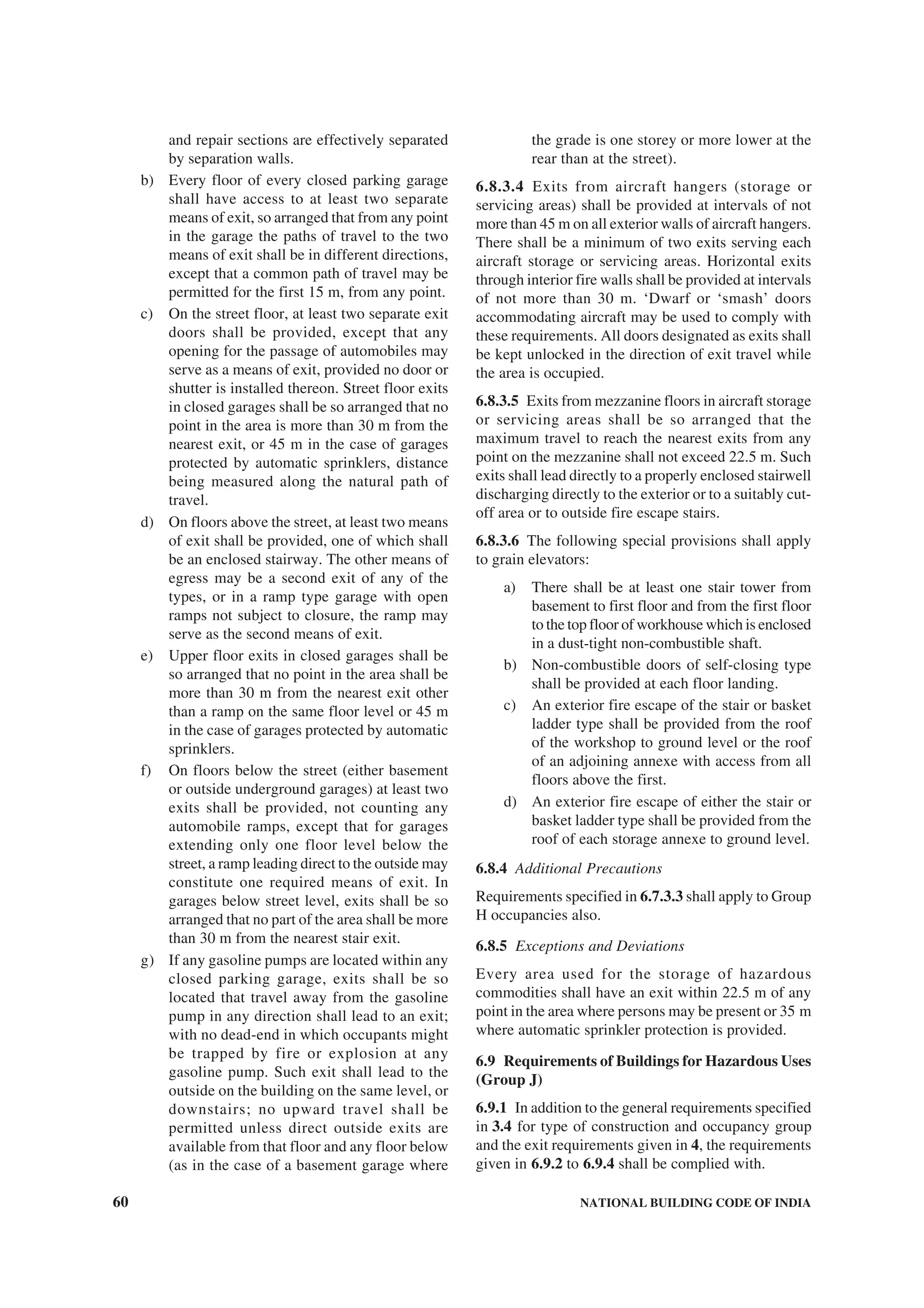
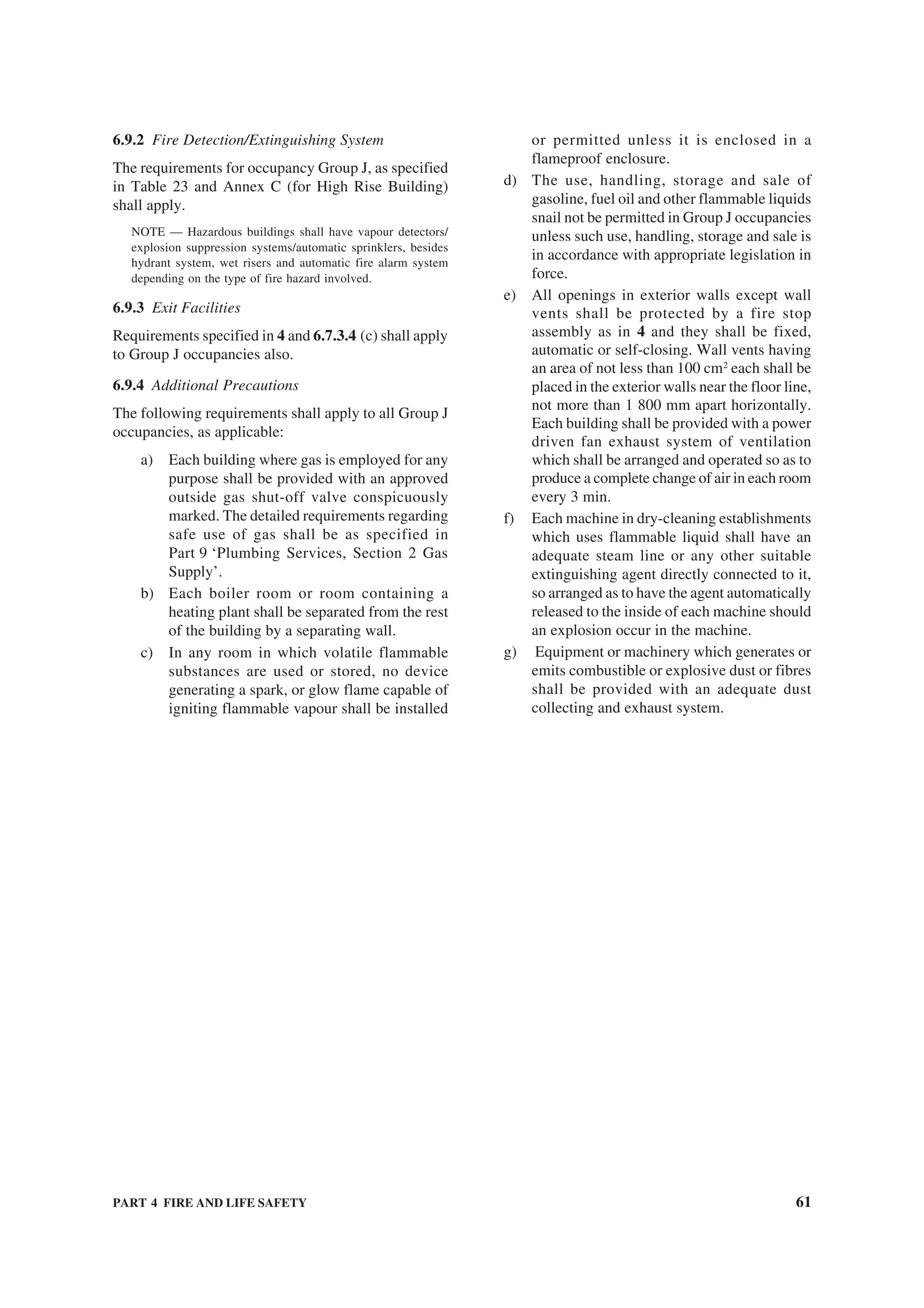
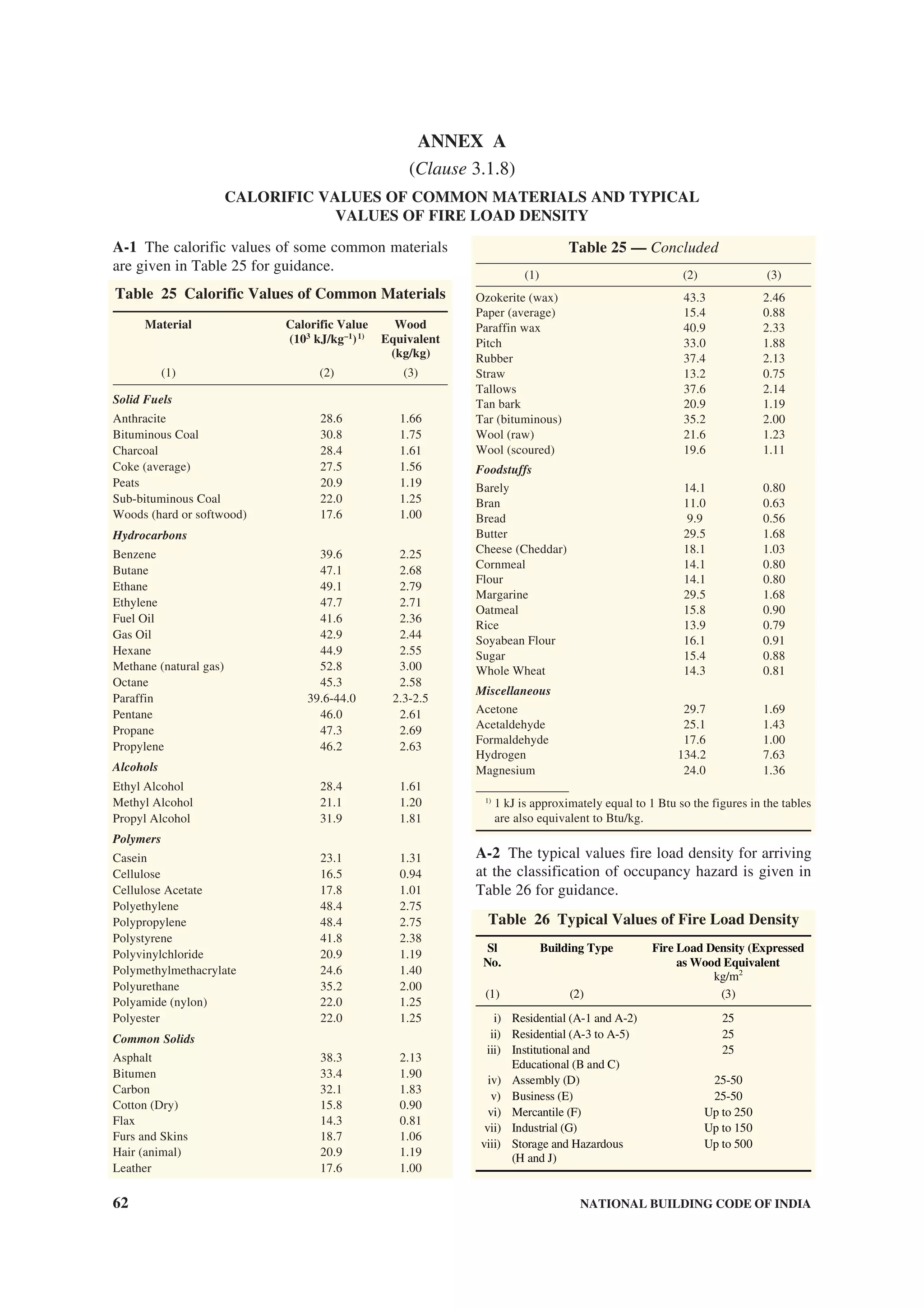
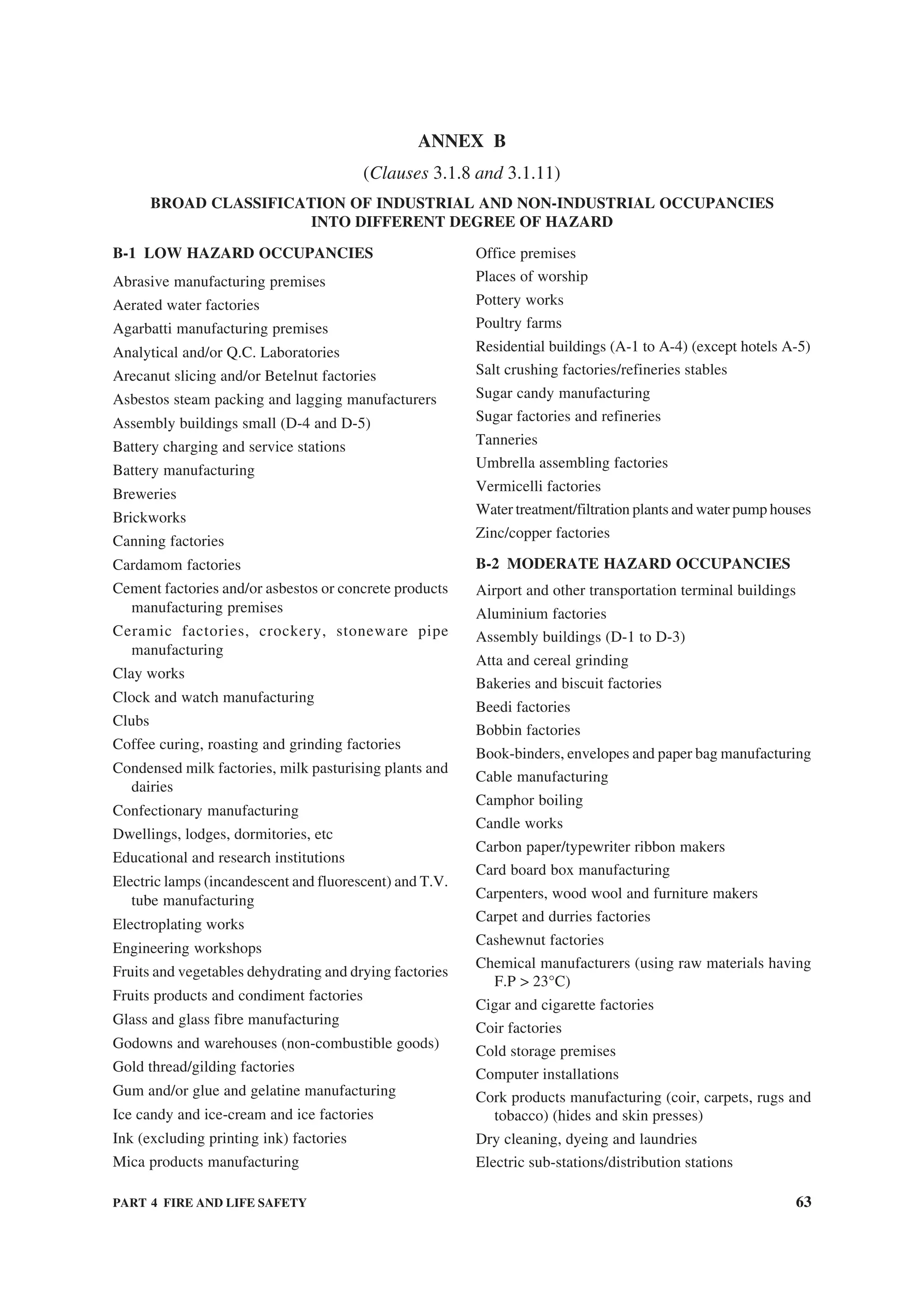
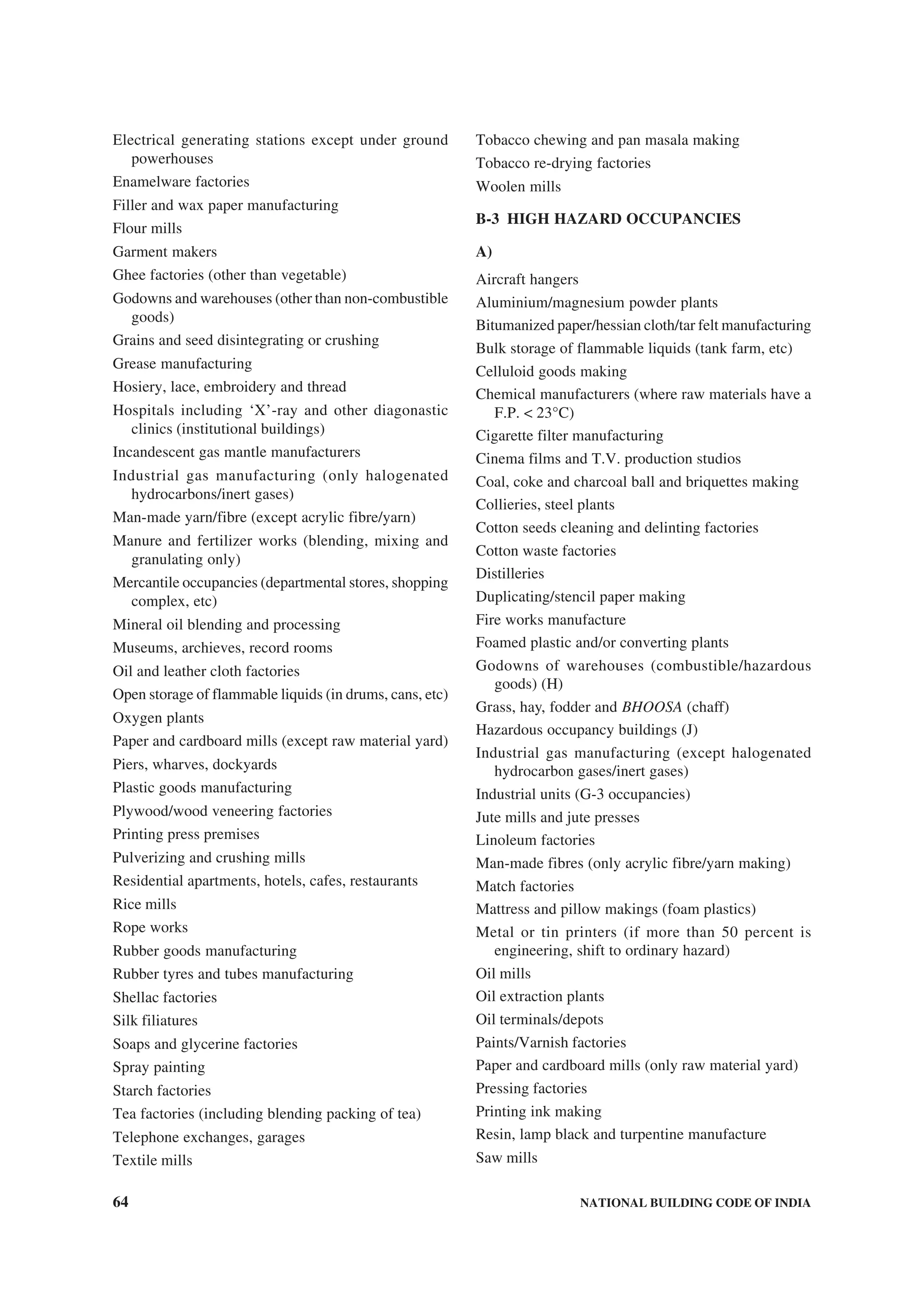
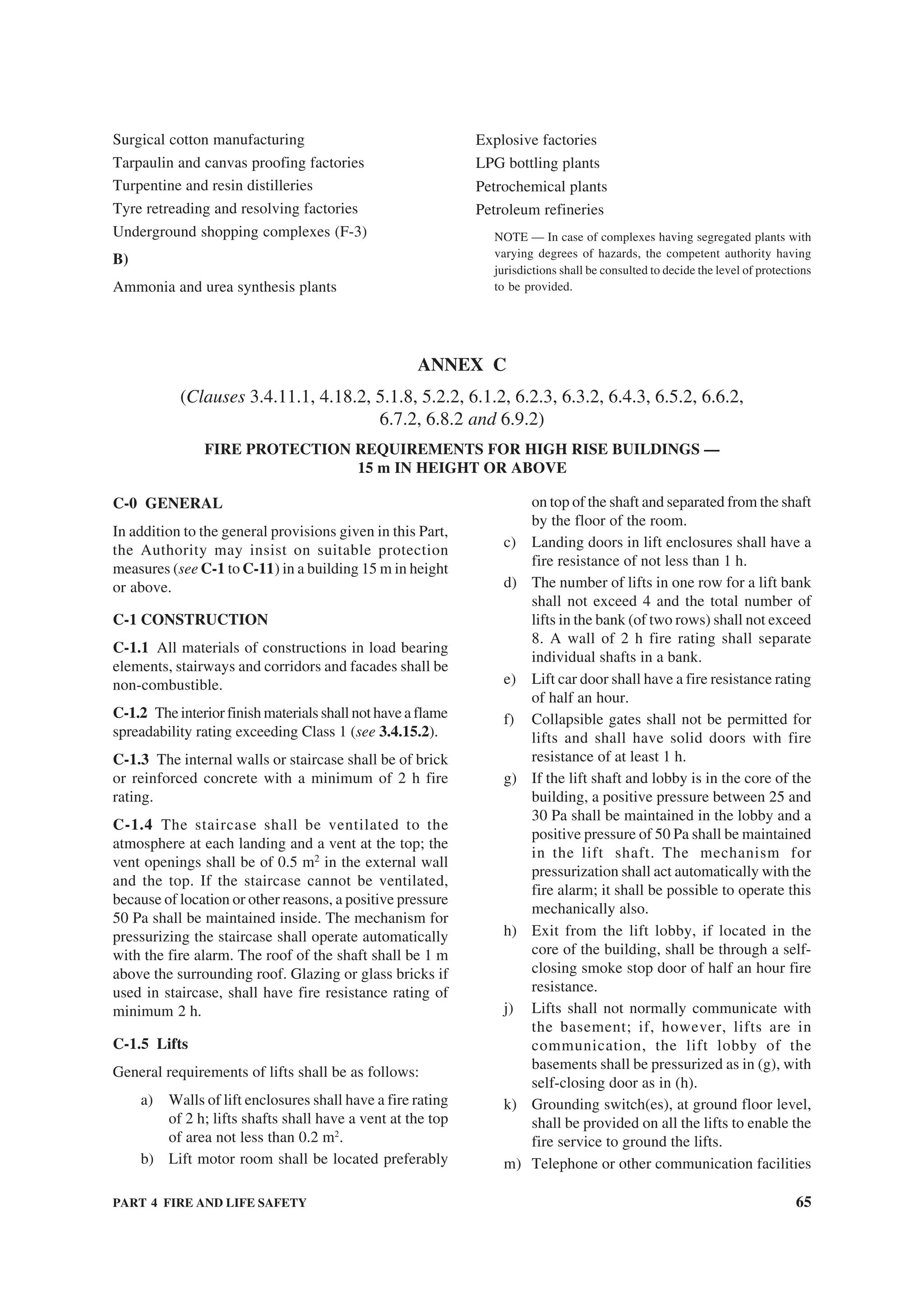
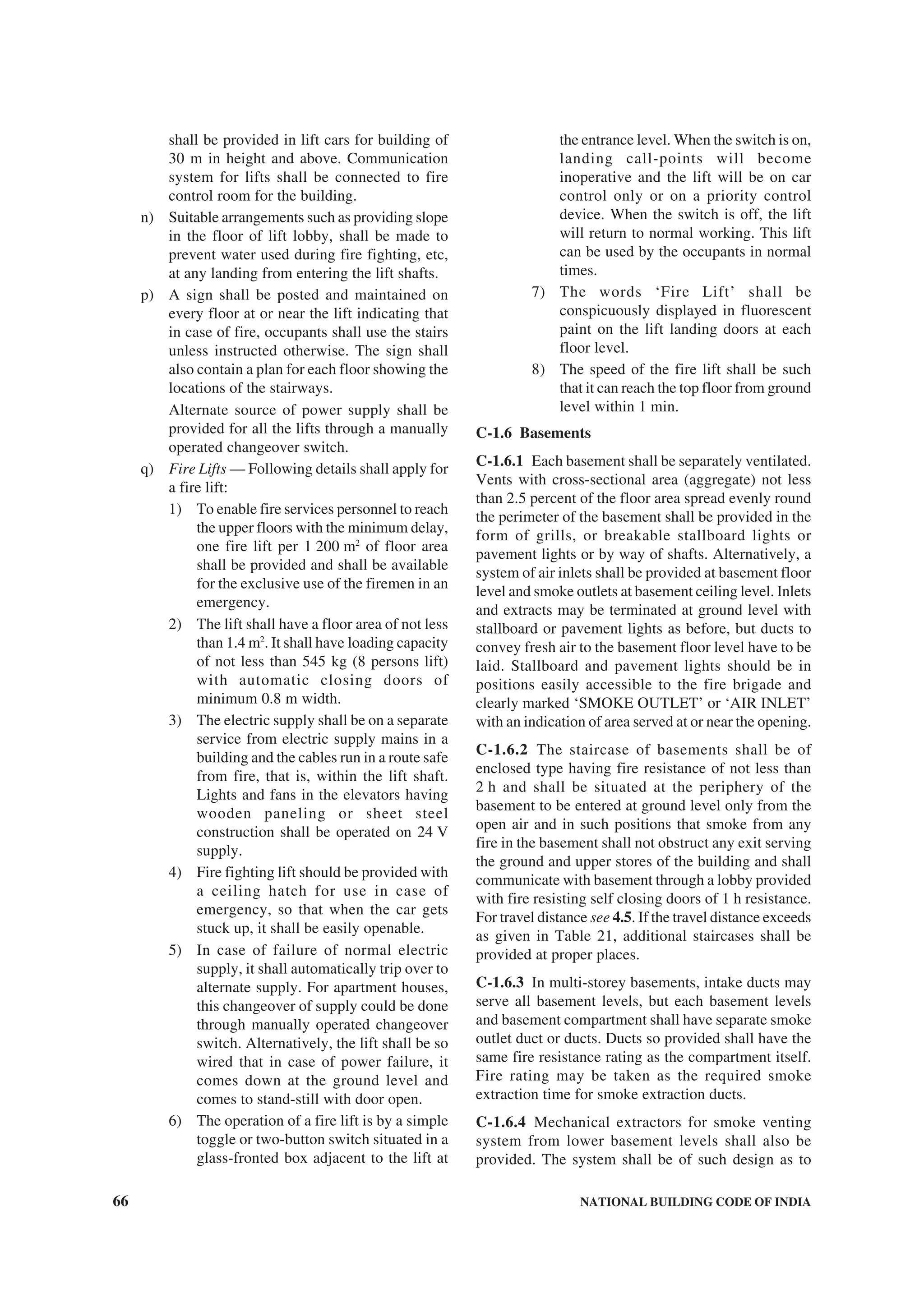
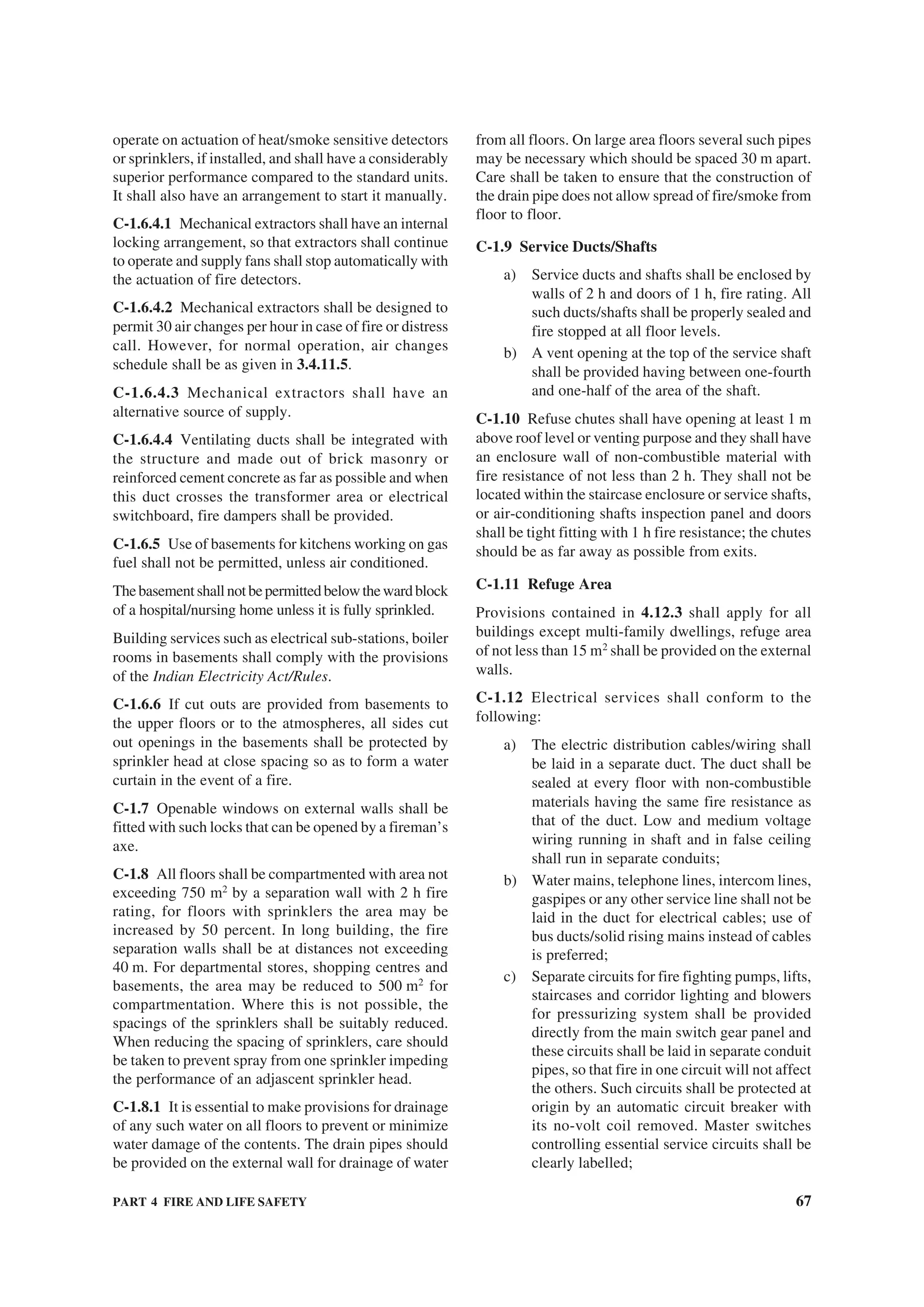
![68 NATIONAL BUILDING CODE OF INDIA
d) The inspection panel doors and any other
opening in the shaft shall be provided with
air-tight fire doors having fire resistance of
not less than 2 h;
e) Medium and low voltage wiring running in
shafts, and within false ceiling shall run in
metal conduit. Any 230 V wiring for lighting
or other services, above false ceiling, shall
have 660 V grade insulation. The false ceiling,
including all fixtures used for its suspension,
shall be of non-combustible material and shall
provide adequate fire resistance to the ceiling
in order to prevent spread of fire across ceiling
reference may be made to good practice
[4(29)];
f) An independent and well ventilated service
room shall be provided on the ground level or
first basement with direct access from outside
or from the corridor for the purpose of
termination of electric supply from the
licensees’ service and alternative supply cables.
The doors provided for the service room shall
have fire resistance of not less than 2 h;
NOTE — If service room is located at the first basement,
it should have automatic fire extinguishing system.
g) If the licensees agree to provide meters on
upper floors, the licensees’ cables shall be
segregated from consumers’ cables by
providing a partition in the duct. Meter rooms
on upper floors shall not open into stair case
enclosures and shall be ventilated directly to
open air outside; and
h) Suitable circuit breakers shall be provided at
the appropriate points.
C-1.13 Gas supply shall conform to the following:
a) Town Gas/L.P. Gas Supply Pipes — Where
gas pipes are run in buildings, the same shall
be run in separate shafts exclusively for this
purpose and these shall be on external walls,
away from the staircases. There shall no
interconnection of this shaft with the rest of
the floors. LPG distribution pipes shall always
be below the false ceiling. The length of these
pipes shall be as short as possible. In the case
of kitchen cooking range area, apart from
providing hood, covering the entire cooking
range, the exhaust system should be designed
to take care of 30 m3
per minute per m2
of
hood protected area. It should have grease
filters using metallic grill to trap oil vapours
escaping into the fume hood.
NOTE — For detailed information on gas pipe
installations, reference may be made to Part 9 ‘Plumbing
Services, Section 3 Gas Supply’.
b) All wiring in fume hoods shall be of fibre
glass insulation. Thermal detectors shall be
installed into fume hoods of large kitchens
for hotels, hospitals, and similar areas located
in high rise buildings. Arrangements shall be
made for automatic tripping of the exhaust
fan in case of fire. If LPG is used, the same
shall be shut off. The voltage shall be 24 V or
100 V dc operated with external rectifier. The
valve shall be of the hand re-set type and shall
be located in an area segregated from cooking
ranges. Valves shall be easily accessible. The
hood shall have manual facility for steam or
carbon dioxide gas injection, depending on
duty condition; and
c) Gas meters shall be housed in a suitably
constructed metal cupboard located in a well
ventilated space, keeping in view the fact that
LPG is heavier than air and town gas is lighter
than air.
C-1.14 Illumination of Means of Exit
Staircase and corridor lights shall conform to the
following (see 4.16 and 4.17 for additional details):
a) The staircase and corridor lighting shall be
on separate circuits and shall be independently
connected so as it could be operated by one
switch installation on the ground floor easily
accessible to fire fighting staff at any time
irrespective of the position of the individual
control of the light points, if any. It should be
of miniature circuit breaker type of switch so
as to avoid replacement of fuse in case of
crisis;
b) Staircase and corridor lighting shall also be
connected to alternative supply. The
alternative source of supply may be provided
by battery continuously trickle charged from
the electric mains;
c) Suitable arrangements shall be made by
installing double throw switches to ensure that
the lighting installed in the staircase and the
corridor does not get connected to two sources
of supply simultaneously. Double throw
switch shall be installed in the service room
for terminating the stand-by supply;
d) Emergency lights shall be provided in the
staircase and corridor; and
e) All wires and other accessories used for
emergency light shall have fire retardant
property.
C-1.15 A stand-by electric generator shall be installed
to supply power to staircase and corridor lighting
circuits, fire lifts, the stand-by fire pump, pressurization](https://image.slidesharecdn.com/is-200203030013/75/NATIONAL-BUILDING-CODE-SP7-180-2048.jpg)
![PART 4 FIRE AND LIFE SAFETY 69
fans and blowers, smoke extraction and damper
systems in case of failure of normal electric supply.
The generator shall be capable of taking starting current
of all the machines and circuits stated above
simultaneously. If the stand-by pump is driven by diesel
engine, the generator supply need not be connected to
the stand-by pump. Where parallel HV/LV supply from
a separate sub-station is provided with appropriate
transformer for emergency, the provision of generator
may be waived in consultation with the Authority.
C-1.16 Transformers shall conform to the following:
a) A sub-station or a switch-station with oil filled
equipment shall not be located in the building.
The sub-station structure shall have separate
fire resisting walls/surroundings and shall
necessarily be located at the periphery of the
floor having separate access from fire escape
stair case. The outside walls, ceiling, floor,
openings including doors and windows to the
sub-station area shall be provided with a fire
resisting door of 2 h fire rating. Direct access
to the transformer room shall be provided,
preferably from outside fire escape staircase.
b) The sub-station area needs to be maintained at
negative air pressures and area in sub-station
shall not be used as storage/dump areas.
c) When housed inside the building, the
transformer shall be of dry type and shall be
cut off from the other portion of premises by
walls/doors/cutout having fire resistance
rating of 4 h.
C-1.17 Air-conditioning shall conform to the
following:
a) Escape routes like staircases, common
corridors, lift lobbies, etc, shall not be used
as return air passage.
b) The ducting shall be constructed of substantial
gauge metal in accordance with good practice
[4(31].
c) Wherever the ducts pass through fire walls or
floors, the opening around the ducts shall be
sealed with materials having fire resistance
rating of the compartment.
d) Where duct crosses a compartment which is
fire rated, the ducts shall be fire rated for same
fire rating. Further depending on services
passing around the duct work, which may get
affected in case of fire temperature rising, the
ducts shall be insulated.
e) As far as possible, metallic ducts shall be used
even for the return air instead of space above
the false ceiling.
f) Where plenum is used for return air passage,
ceiling and its fixtures shall be of non-
combustible material.
g) The materials used for insulating the duct
system (inside or outside) shall be of non-
combustible materials. Glass wool shall not
be wrapped or secured by any material of
combustible nature.
h) Area more than 750 m2
on individual floor
shall be segregated by a fire wall and
automatic fire dampers for isolation shall be
provided [see (j)].
j) Air ducts serving main floor areas, corridors,
etc, shall not pass through the staircase
enclosure.
k) The air-handling units shall be separate for
each floor and air ducts for every floor shall
be separated and in no way inter-connected
with the ducting of any other floor.
m) If the air-handling unit serves more than one
floor, the recommendations given above shall
be complied with in addition to the conditions
given below:
1) proper arrangements by way of automatic
fire dampers working on smoke detector/
or fusible link for isolating all ducting at
every floor from the main riser shall be
made.
2) When the automatic fire alarm operates,
the respective air-handling units of the air-
conditioning system shall automatically
be switched off.
n) The vertical shaft for treated fresh air shall
be of masonry construction.
p) The air filters of the air-handling units shall
be of non-combustible materials.
q) The air-handling unit room shall not be used
for storage of any combustible materials.
r) Inspection panels shall be provided in the
main trunking to facilitate the cleaning of
ducts of accumulated dust and to obtain access
for maintenance of fire dampers.
s) No combustible material shall be fixed nearer
than 150 mm to any duct unless such duct is
properly enclosed and protected with non-
combustible material (glass wool or spunglass
with neoprene facing enclosed and wrapped
withaluminimumsheeting)atleast3.2mmthick
and which would not readily conduct heat.
t) Fire Dampers
1) These shall be located in conditioned air
ducts and return air ducts/passages at the
following points:
i) At the fire separation wall.](https://image.slidesharecdn.com/is-200203030013/75/NATIONAL-BUILDING-CODE-SP7-181-2048.jpg)
![70 NATIONAL BUILDING CODE OF INDIA
ii) Where ducts/passages enter the
central vertical shaft.
iii) Where the ducts pass through floors.
iv) At the inlet of supply air duct and the
return air duct of each compartment
on every floor.
2) The dampers shall operate automatically
and shall simultaneously switch off the
air-handling fans. Manual operation
facilities shall also be provided.
NOTE — For blowers, where extraction system
and duct accumulators are used, dampers shall be
provided.
3) Fire/smoke dampers (for smoke extraction
shafts) for buildings more than 24 m in
height.
For apartment
houses
In non-ventilated
lobbies/ corridors
operated by fusible
link/smoke detectors
and with manual
control.
For other
buildings
On operation of smoke
detection system and
with manual control.
4) Automatic fire dampers shall be so
arranged as to close by gravity in the
direction of air movement and to remain
tightly closed on operation of a fusible
link/smoke detector.
C-1.18 Provisions of boiler and boiler rooms shall
conform to Indian Boiler Act. Further, the following
additional aspects may be taken into account in the
location of boiler room:
a) The boilers shall not be allowed in sub-
basement, but may be allowed in the
basements away from the escape routes.
b) The boilers shall be installed in a fire resisting
room of 4 h fire resistance rating, and this
room shall be situated on the periphery of the
basement. Catch-pits shall be provided at the
low level.
c) Entry to this room shall be provided with a
composite door of 2 h fire resistance.
d) The boiler room shall be provided with fresh
air inlets and smoke exhausts directly to the
atmosphere.
e) The furnace oil tank for the boiler, if located
in the adjoining room shall be separated by
fire resisting wall of 4 h rating. The entrance
to this room shall be provided with double
composite doors. A curb of suitable height
shall be provided at the entrance in order to
prevent the flow of oil into the boiler room in
case of tank rupture.
f) Foam inlets shall be provided on the external
walls of the building near the ground level to
enable the fire services to use foam in case of
fire.
C-2 PROVISIONOFFIRST-AIDFIREFIGHTING
APPLIANCES
The first-aid fire fighting equipment shall be provided
on all floors, including basements, lift rooms, etc, in
accordance with good practice [4(21)] in consultation
with the Authority.
C-3 FIRE ALARM SYSTEM
C-3.1 All buildings with heights of 15 m or above
shall be equipped with manually operated electrical
fire alarm (MOEFA) system and automatic fire alarm
system in accordance with good practice [4(18)] and
[4(19)]. However, apartment buildings between 15 m
and 30 m in height may be exempted from the
installation of automatic fire alarm system provided
the local fire brigade is suitably equipped for dealing
with fire in a building of 15 m in height or above and
in the opinion of the Authority, such building does not
constitute a hazard to the safety of the adjacent property
or occupants of the building itself.
C-3.1.1 Manually operated electrical fire alarm system
shall be installed in a building with one or more call
boxes located at each floor. The call boxes shall
conform to good practice [4(18)] and [4(19)].
C-3.1.2 The installation of call boxes in hostels and
such other places where these are likely to be misused
shall as far as possible be avoided. Location of call boxes
in dwelling units shall preferably be inside the building.
C-4 LIGHTNING PROTECTION OF BUILDINGS
The lightning protection for buildings shall be provided
as given in Part 8 ‘Building Services, Section 2
Electrical Installations’.
C-5 FIRE CONTROL ROOM
For all buildings 15 m in height or above and apartment
buildings with a height of 30 m and above, there shall
be a control room on the entrance floor of the building
with communication system (suitable public address
system) to all floors and facilities for receiving the
message from different floors. Details of all floor plans
along with the details of fire fighting equipment and
installations shall be maintained in the fire control
room. The fire control room shall also have facilities
to detect the fire on any floor through indicator boards
connection; fire detection and alarm systems on all
floors. The fire staff incharge of the fire control room](https://image.slidesharecdn.com/is-200203030013/75/NATIONAL-BUILDING-CODE-SP7-182-2048.jpg)
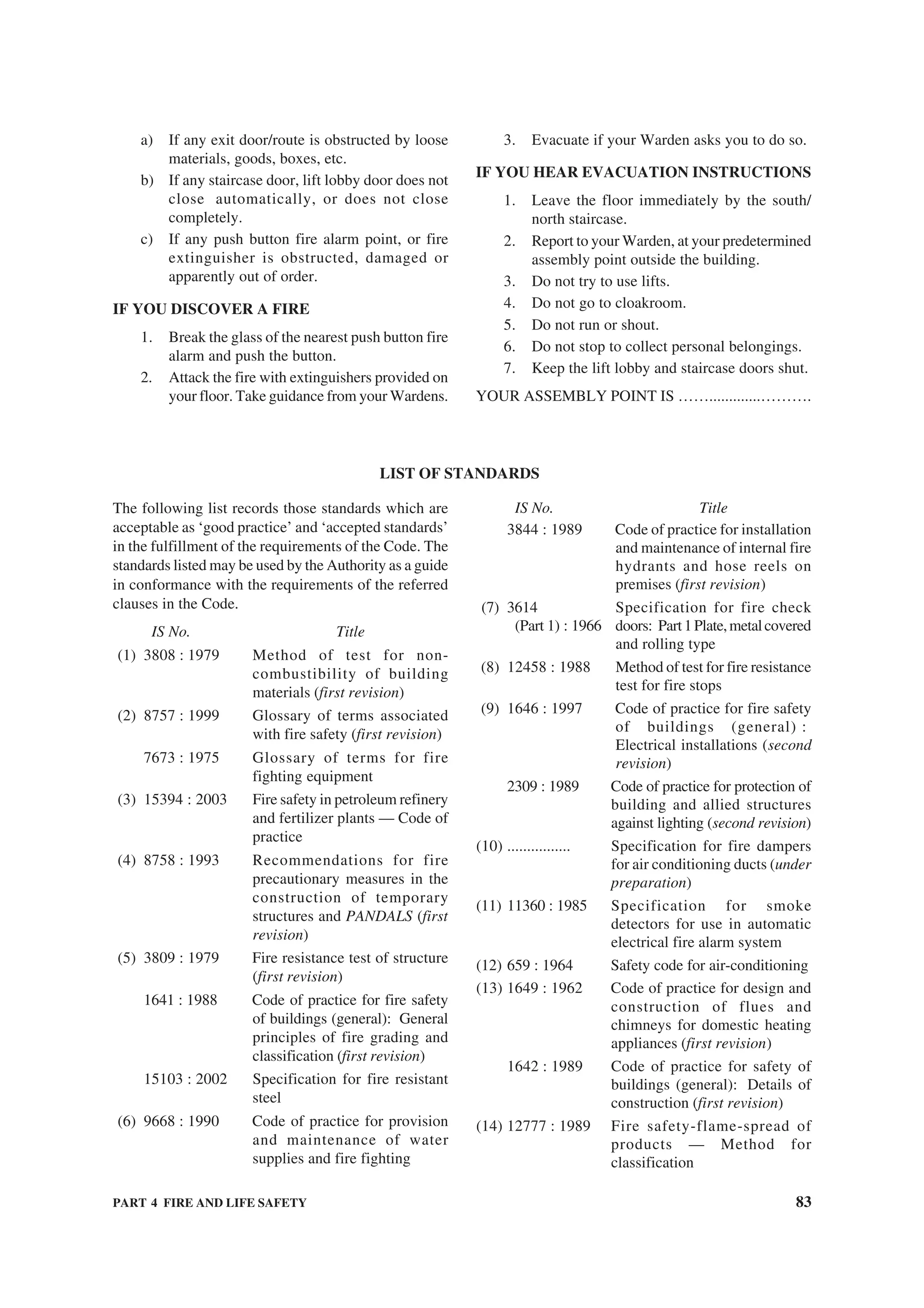
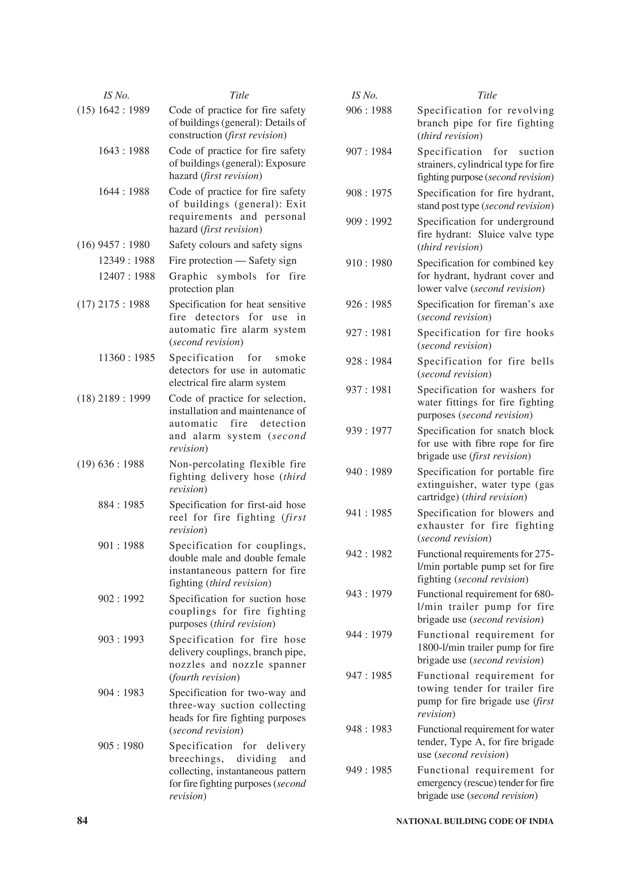
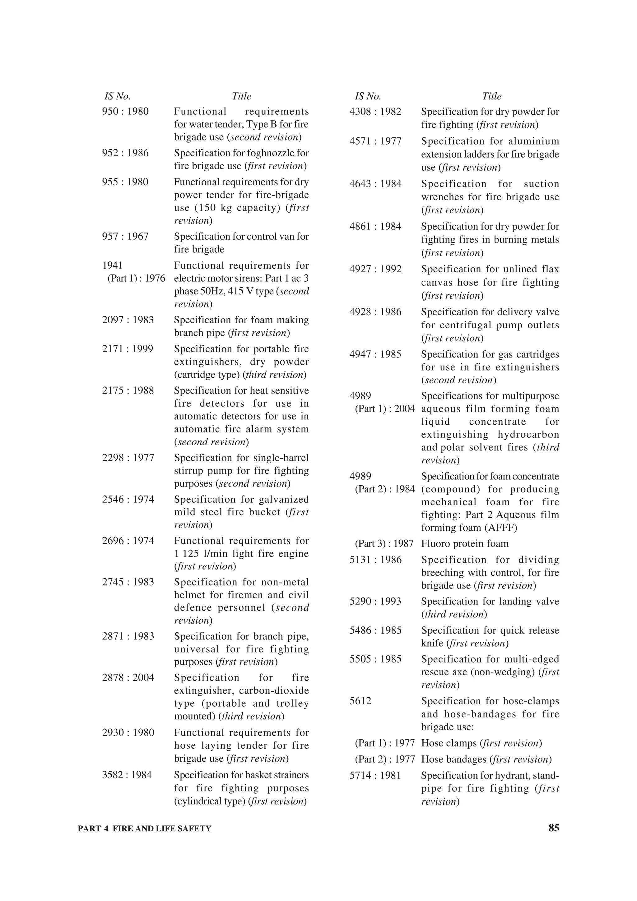
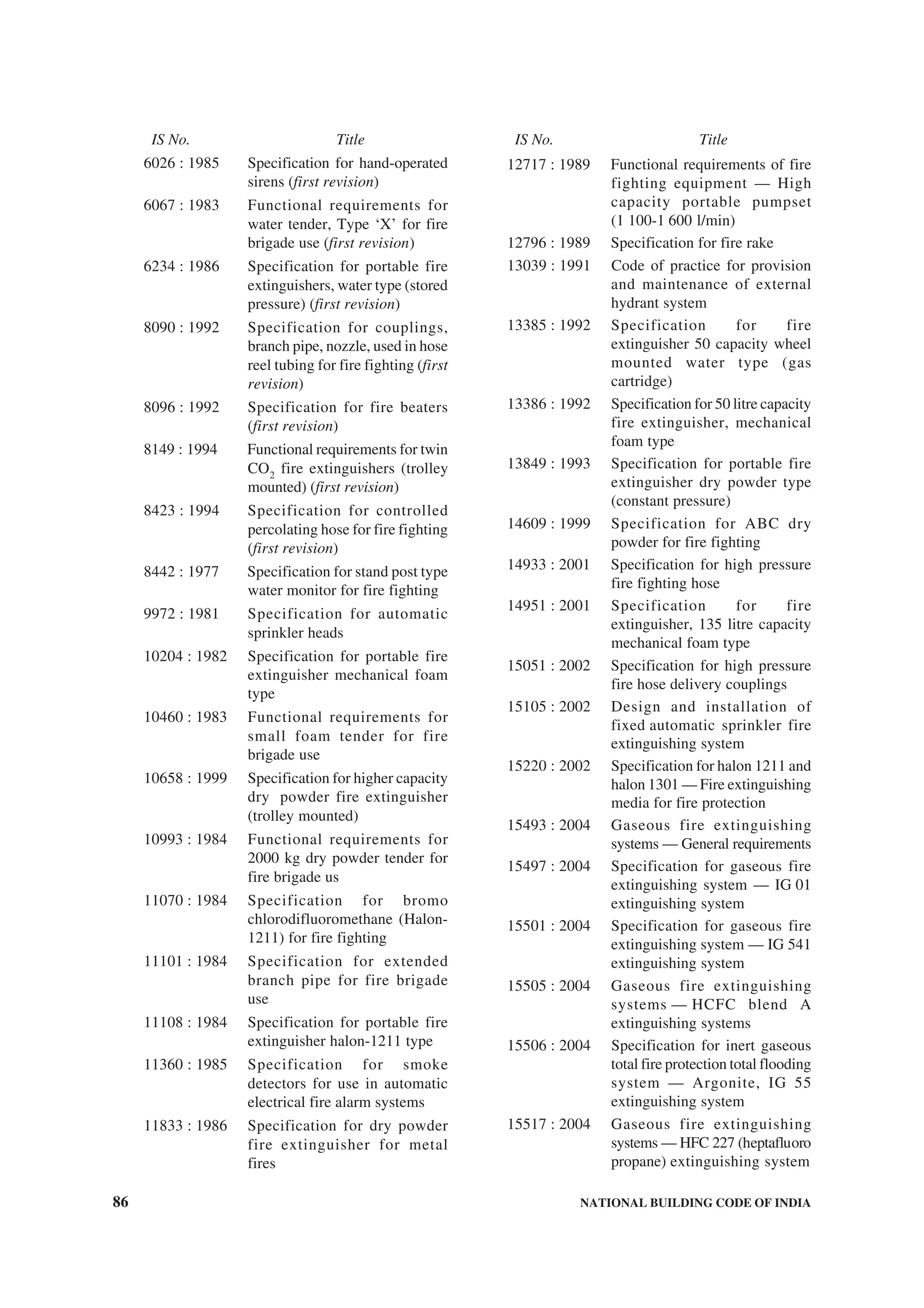
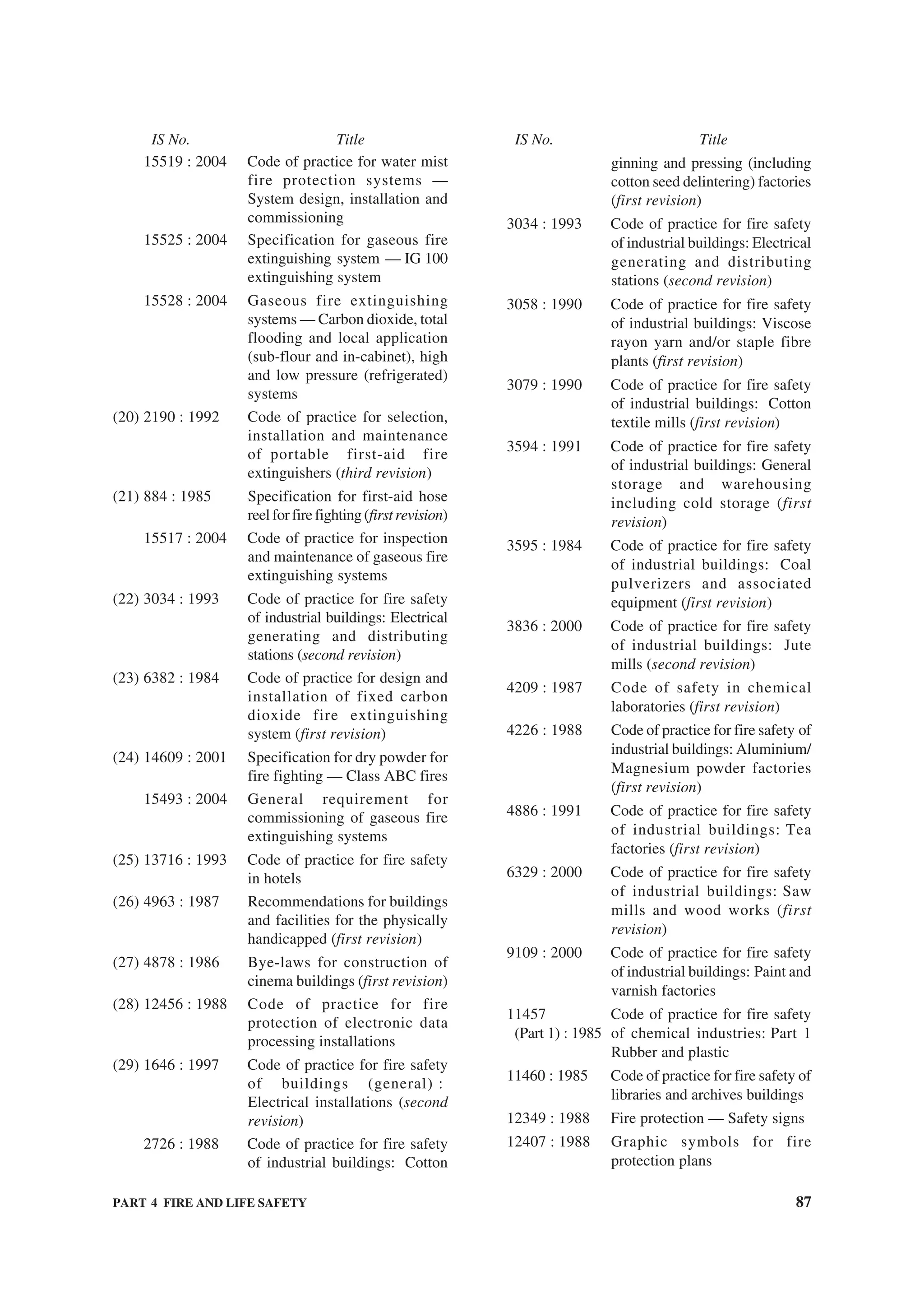
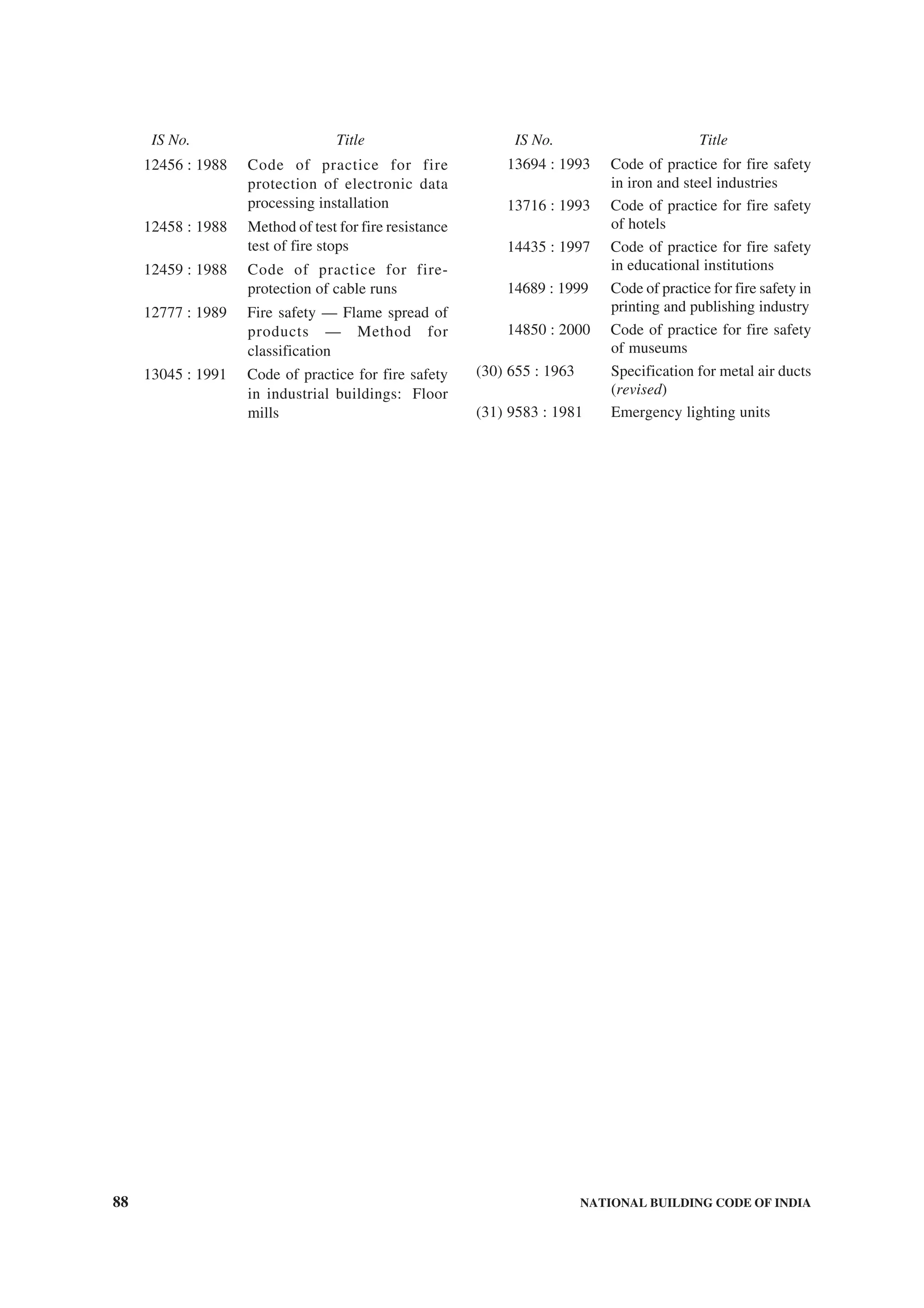
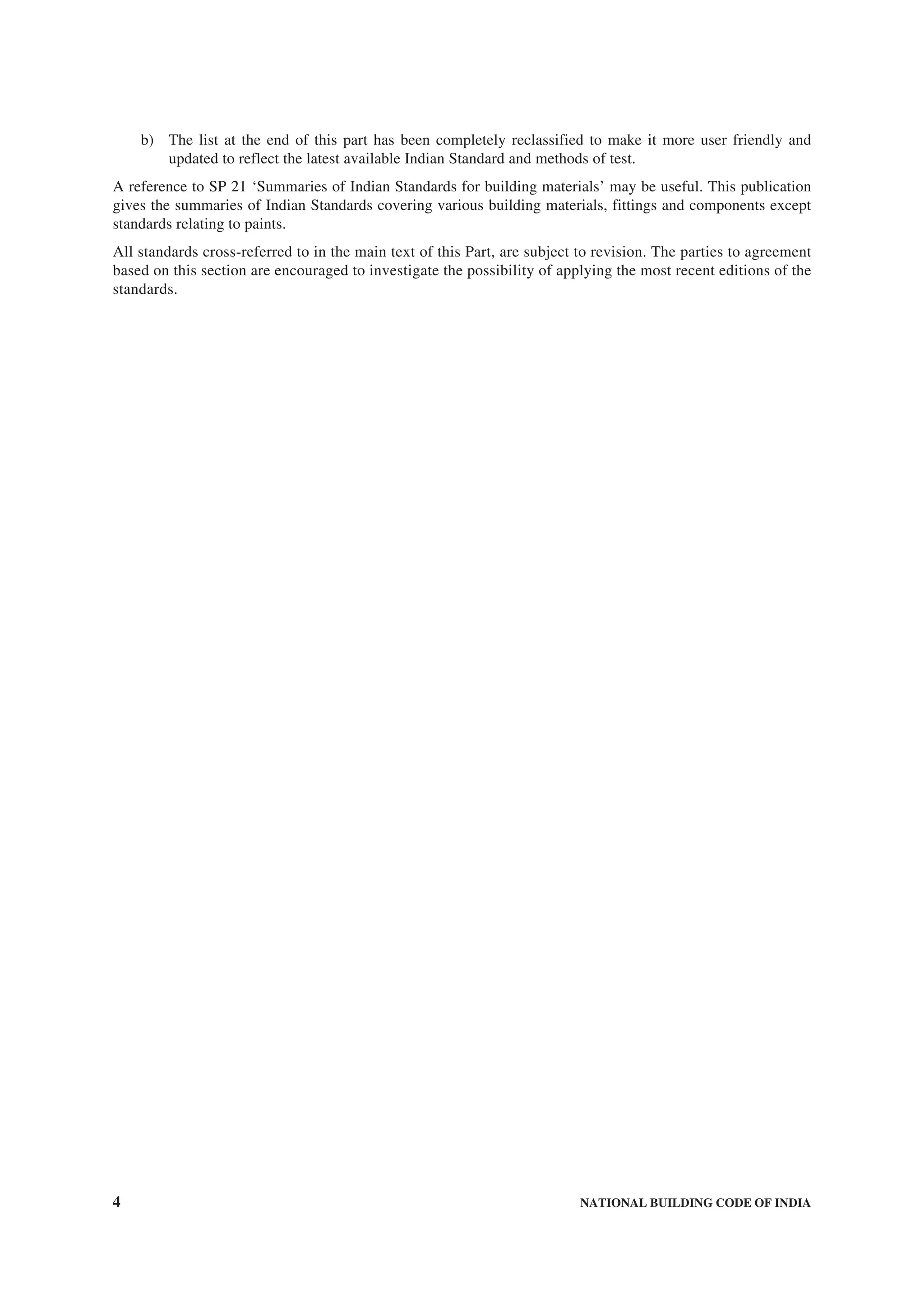
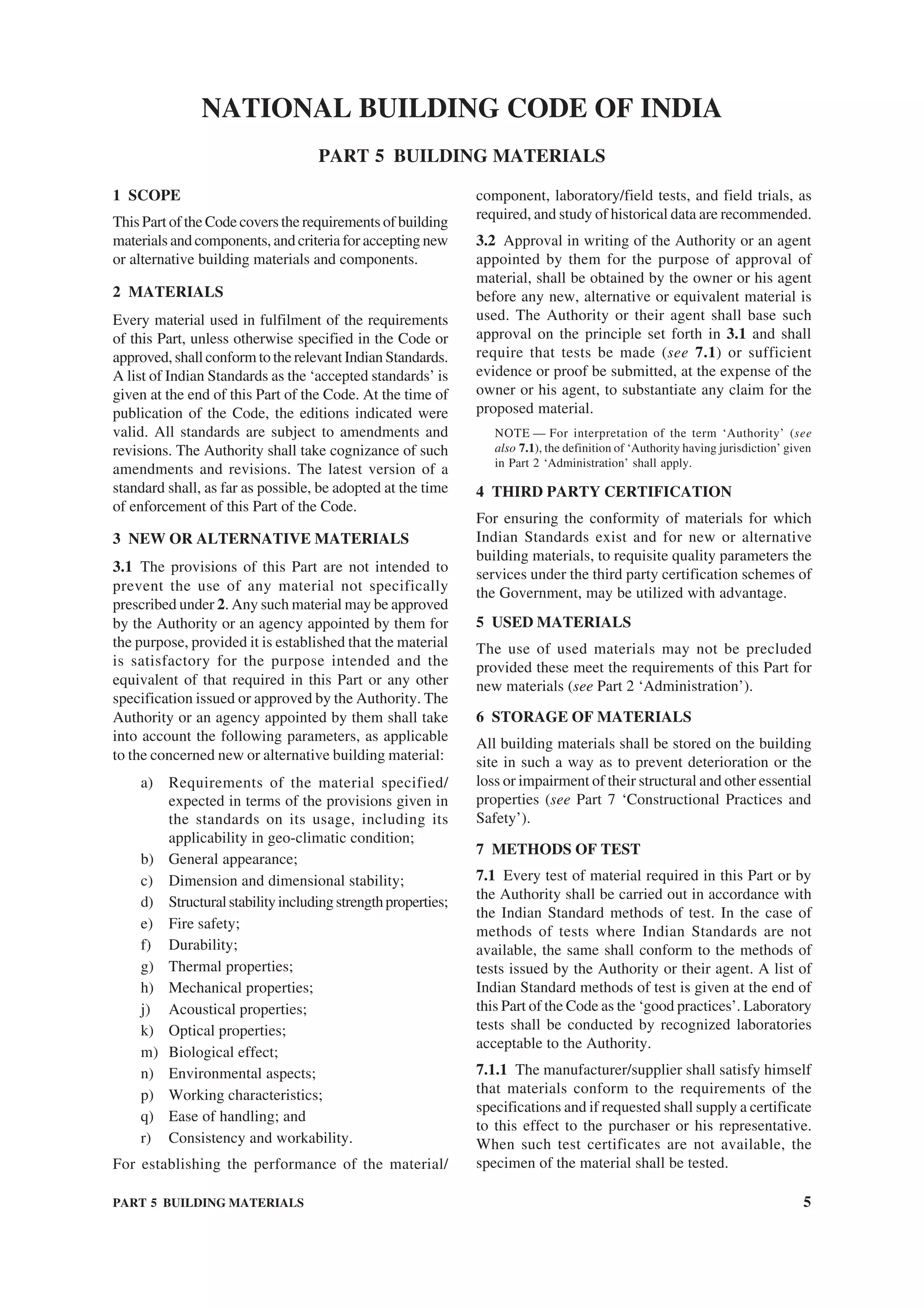
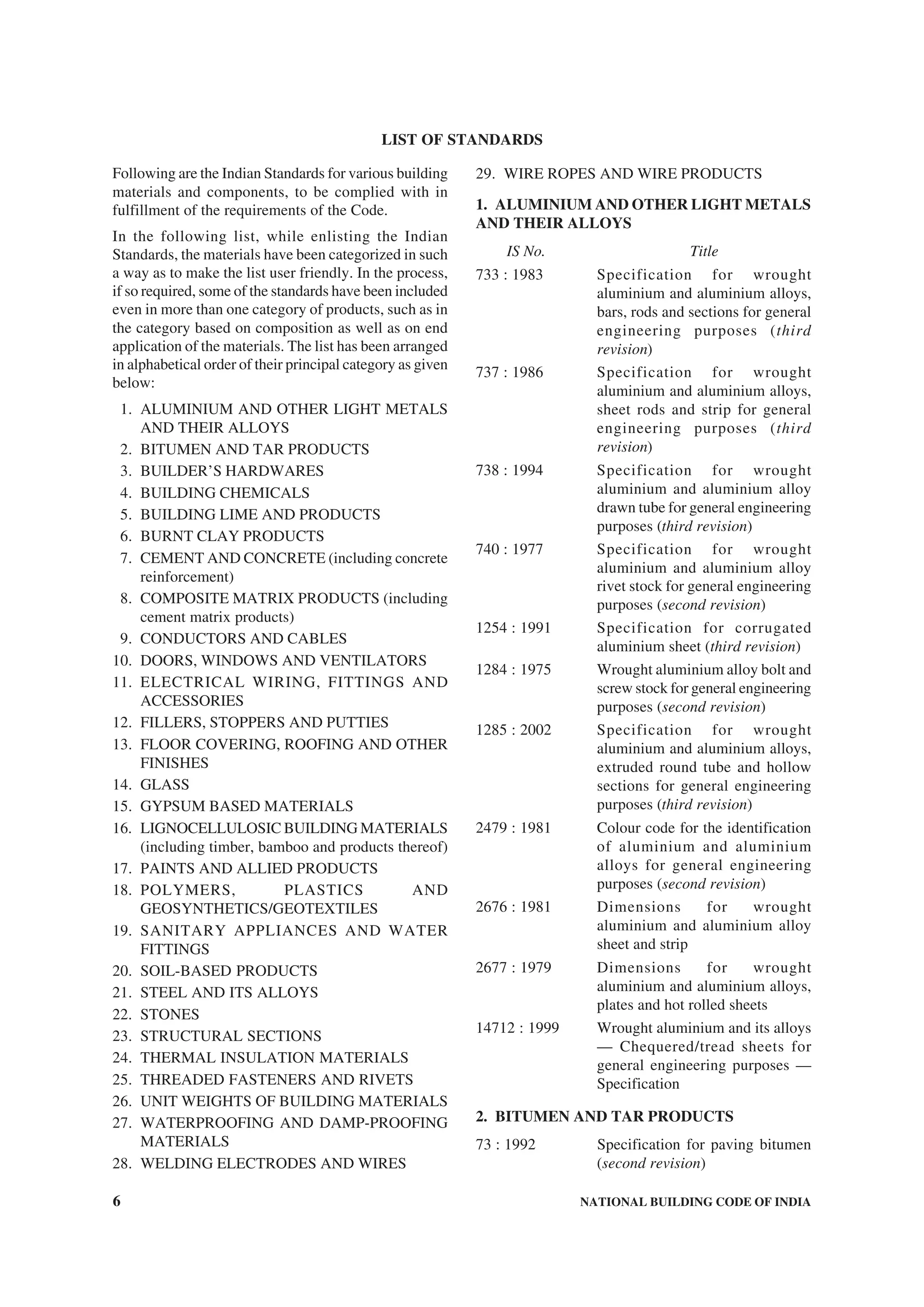
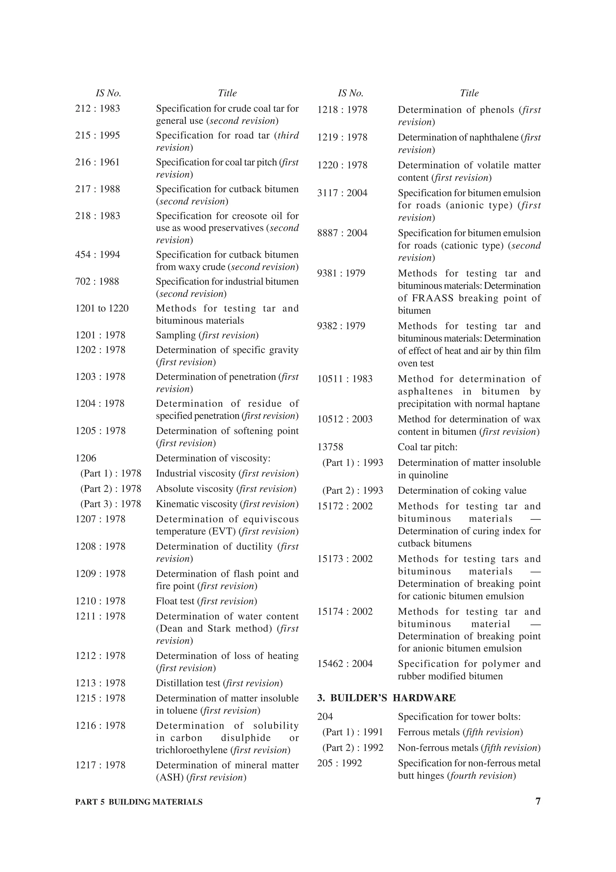
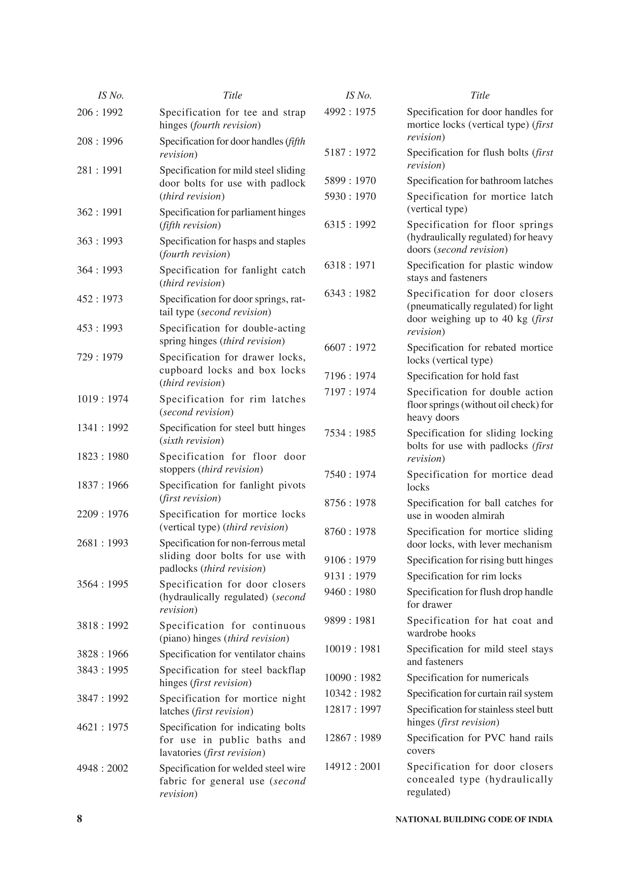
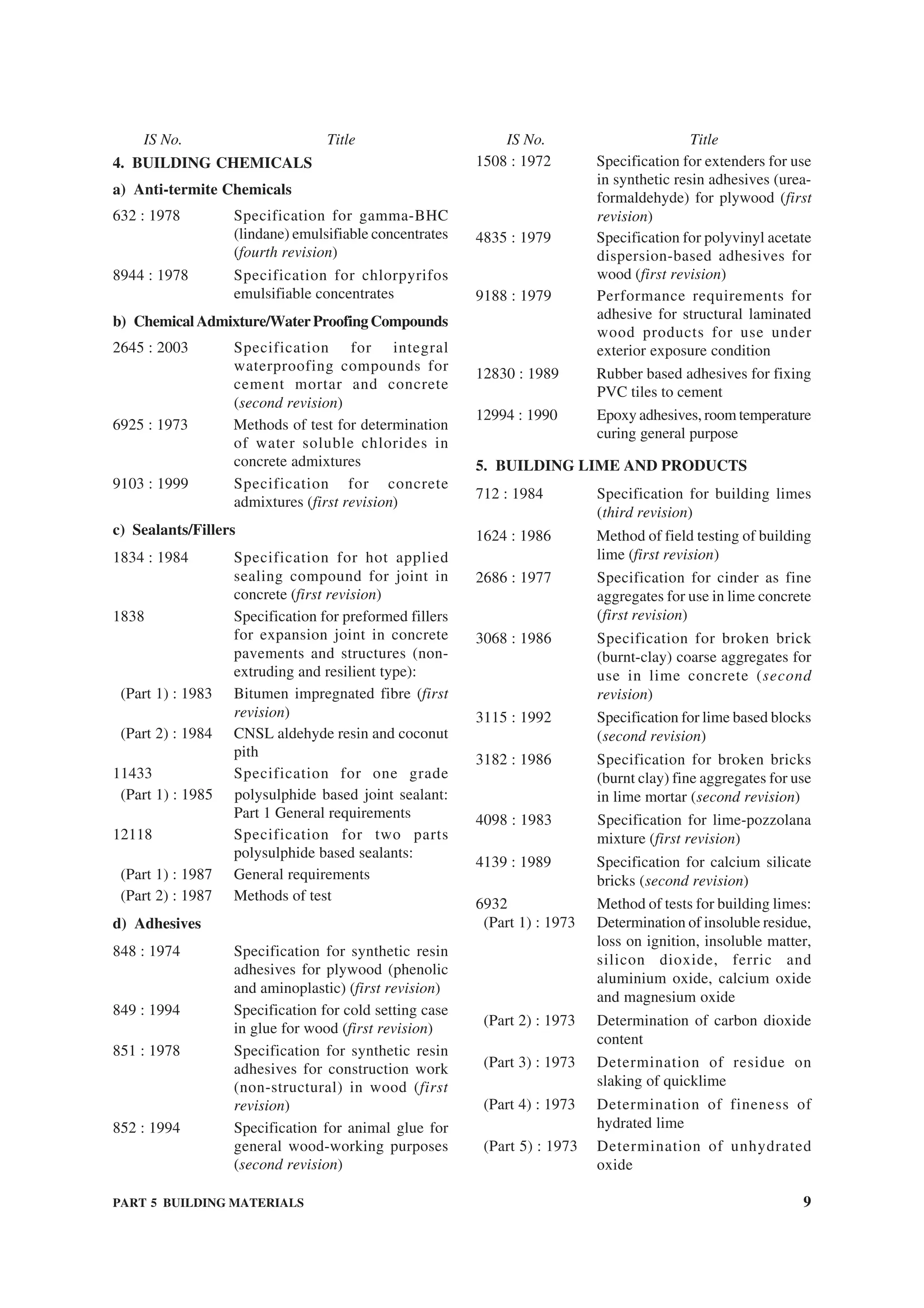
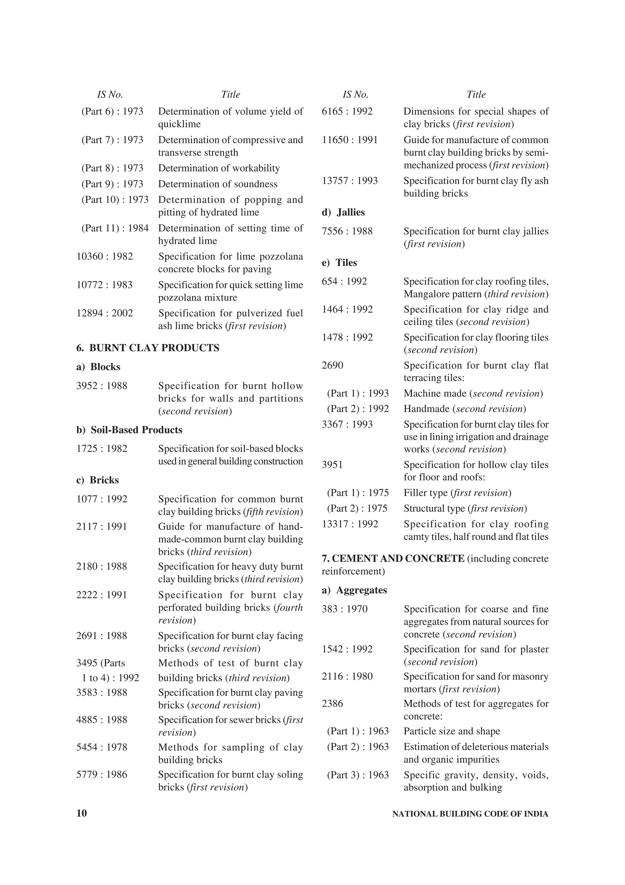
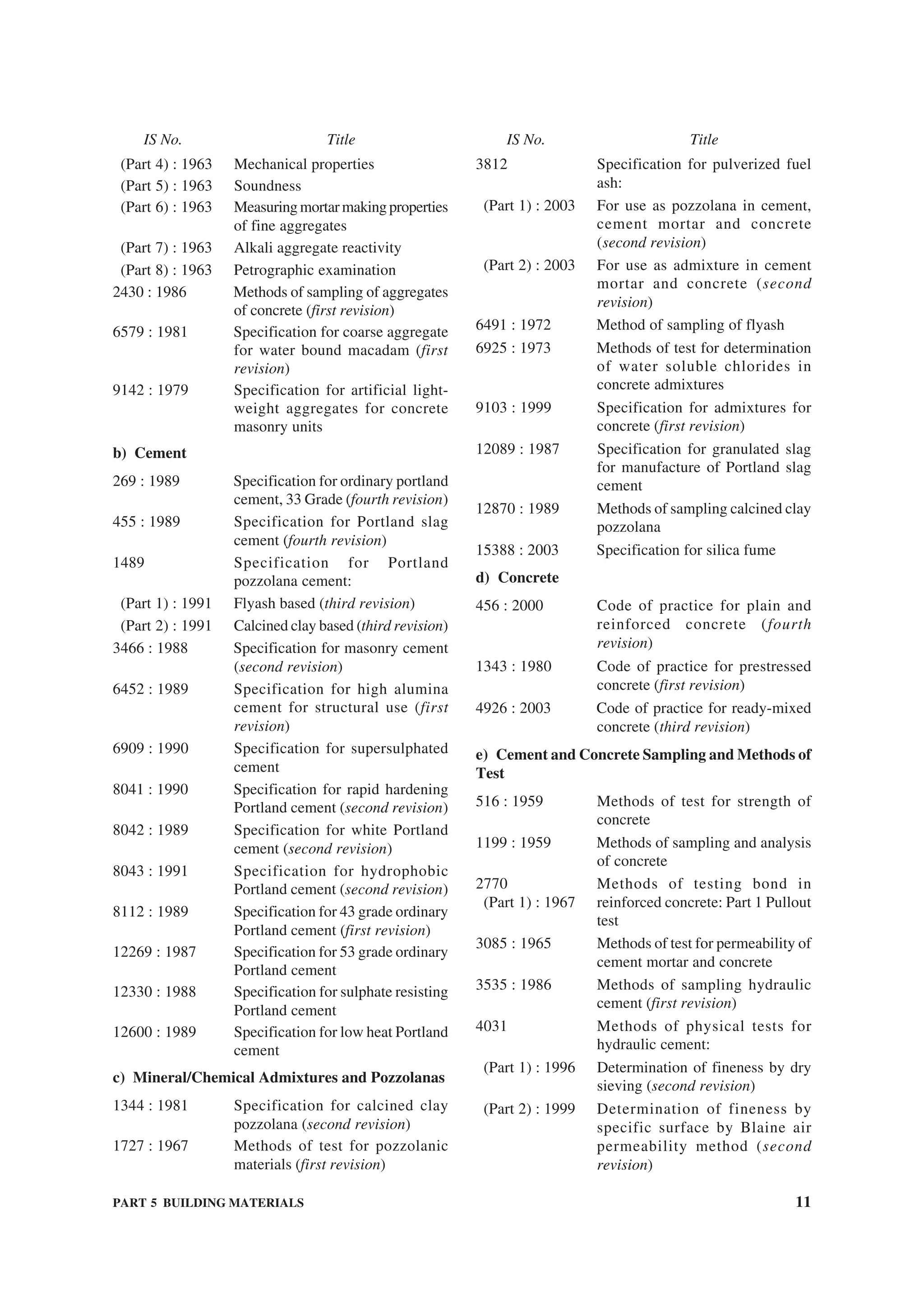
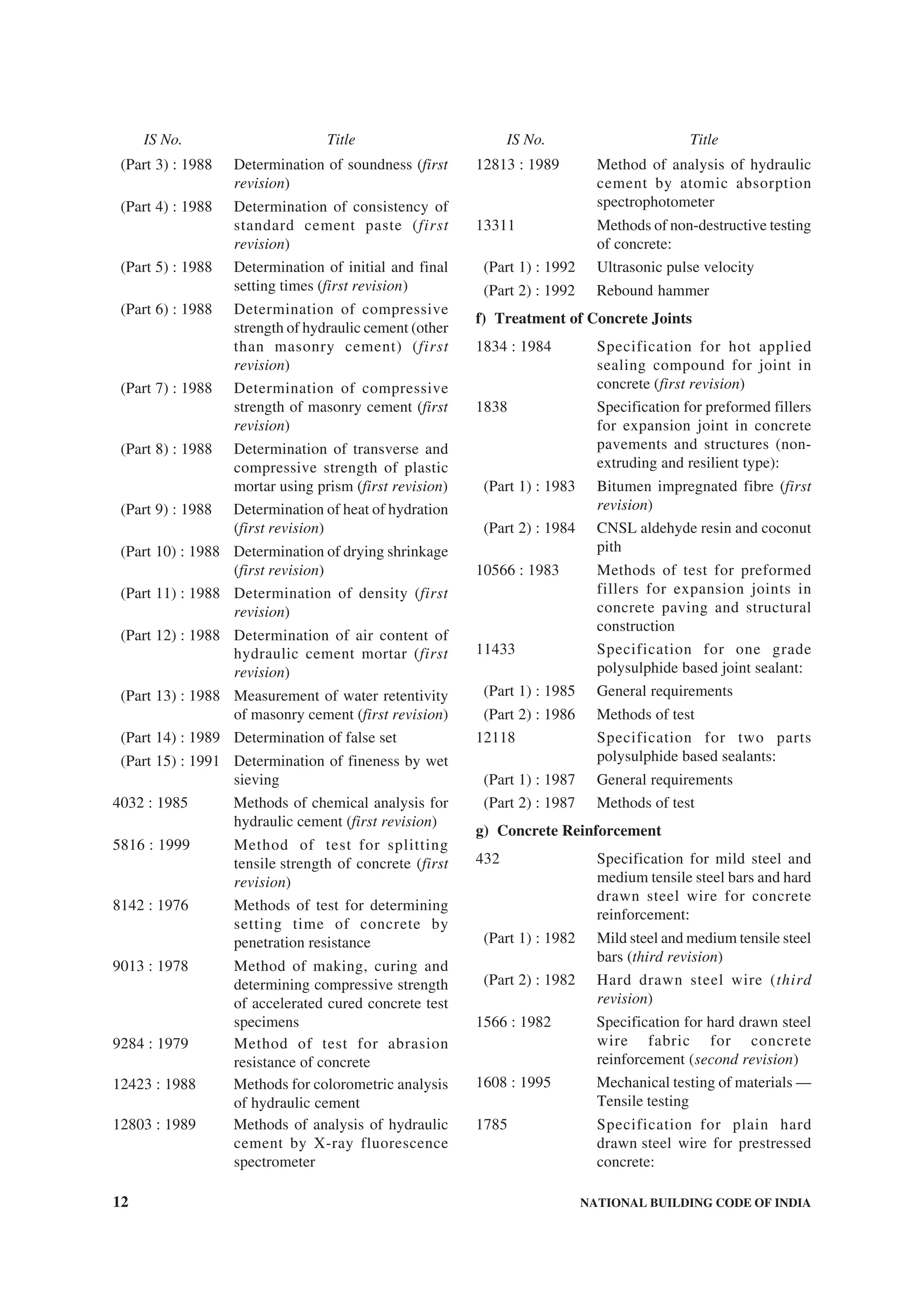
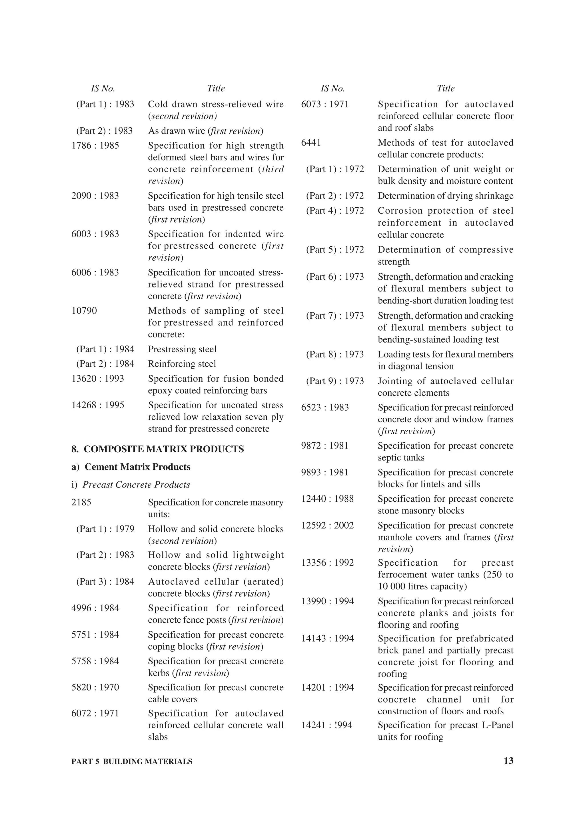
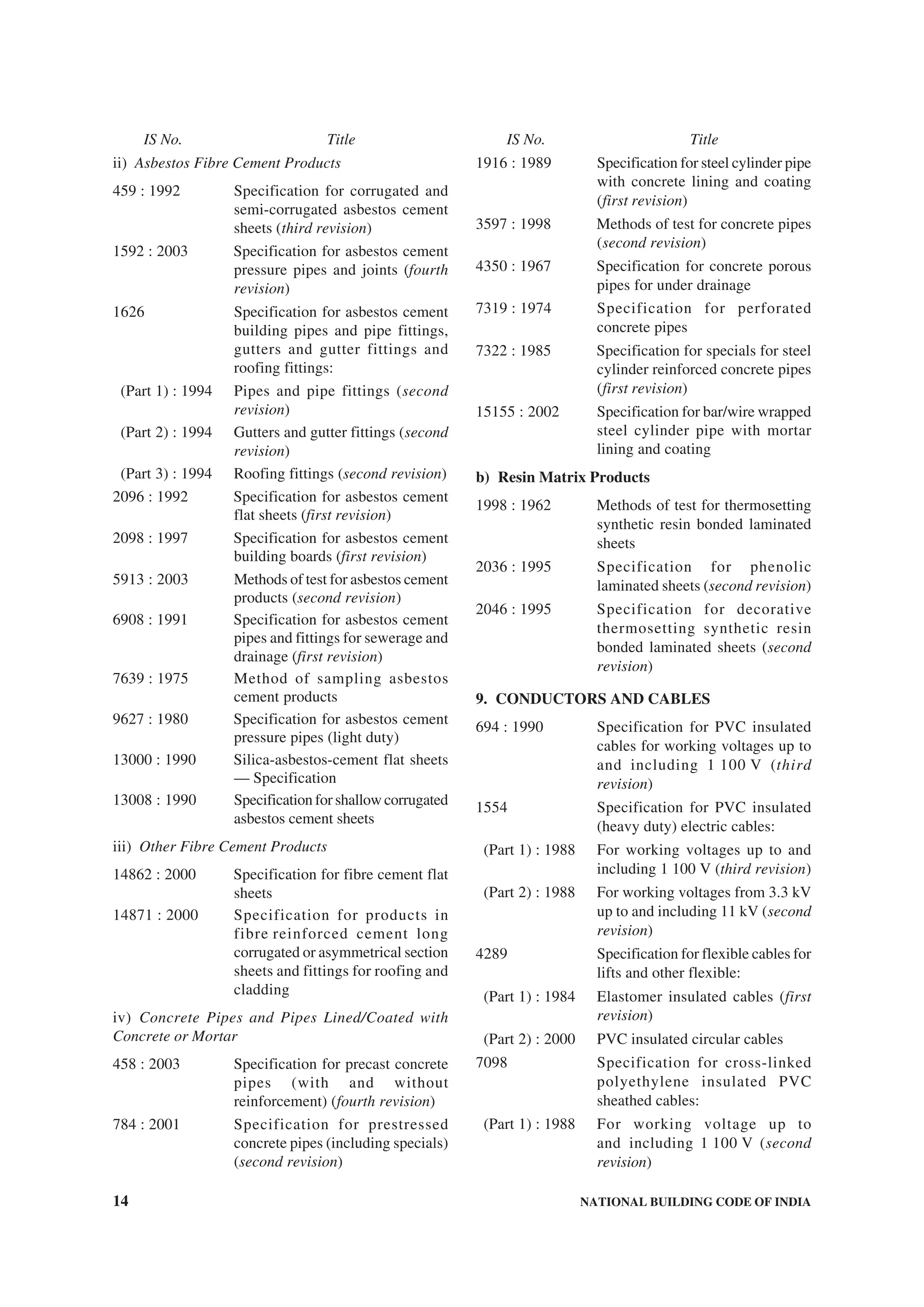
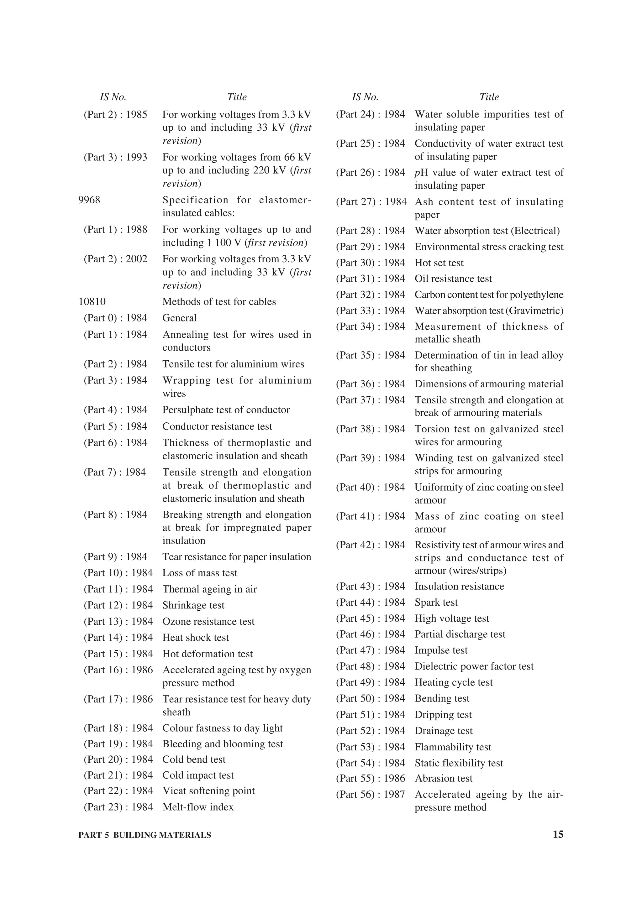
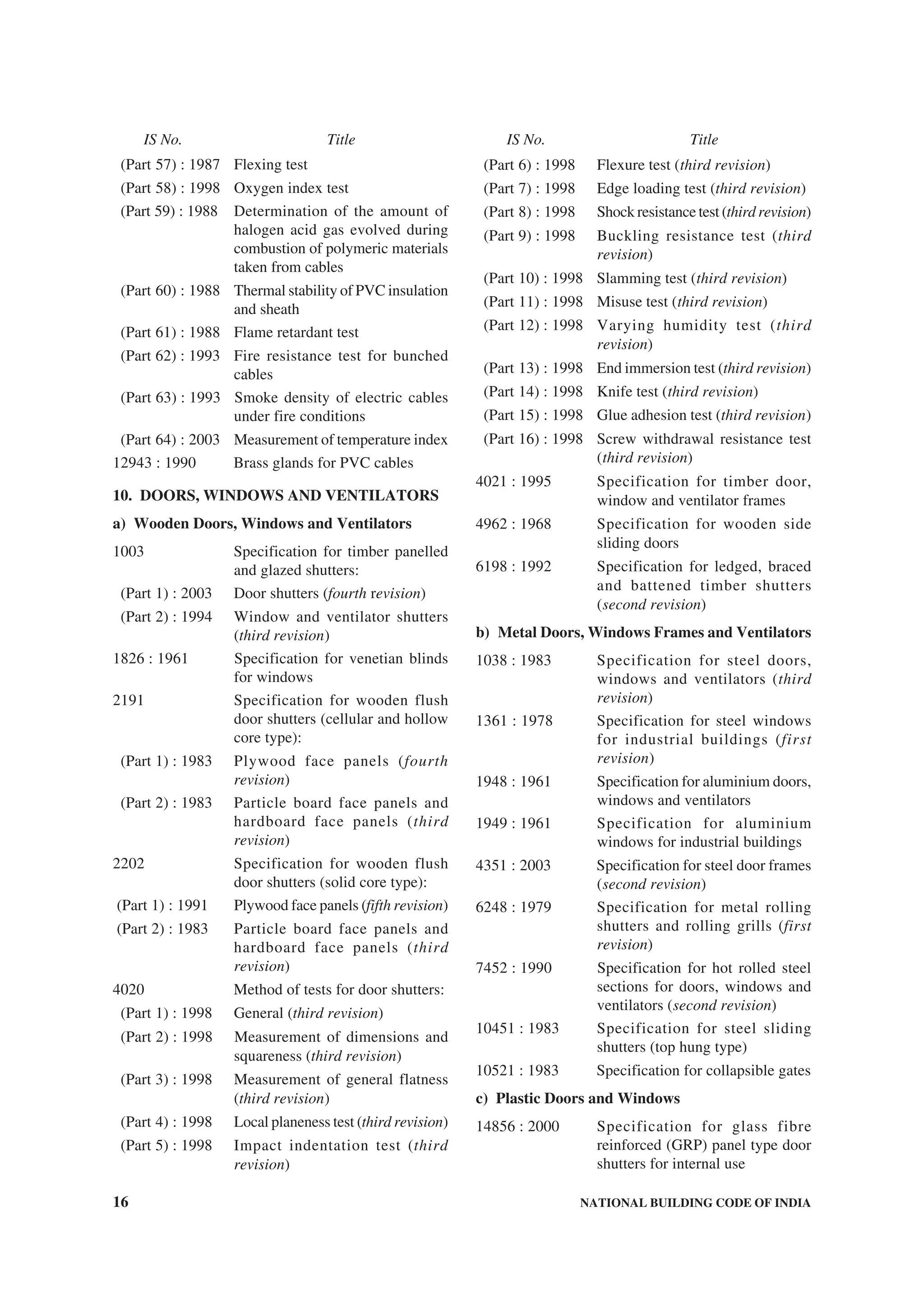
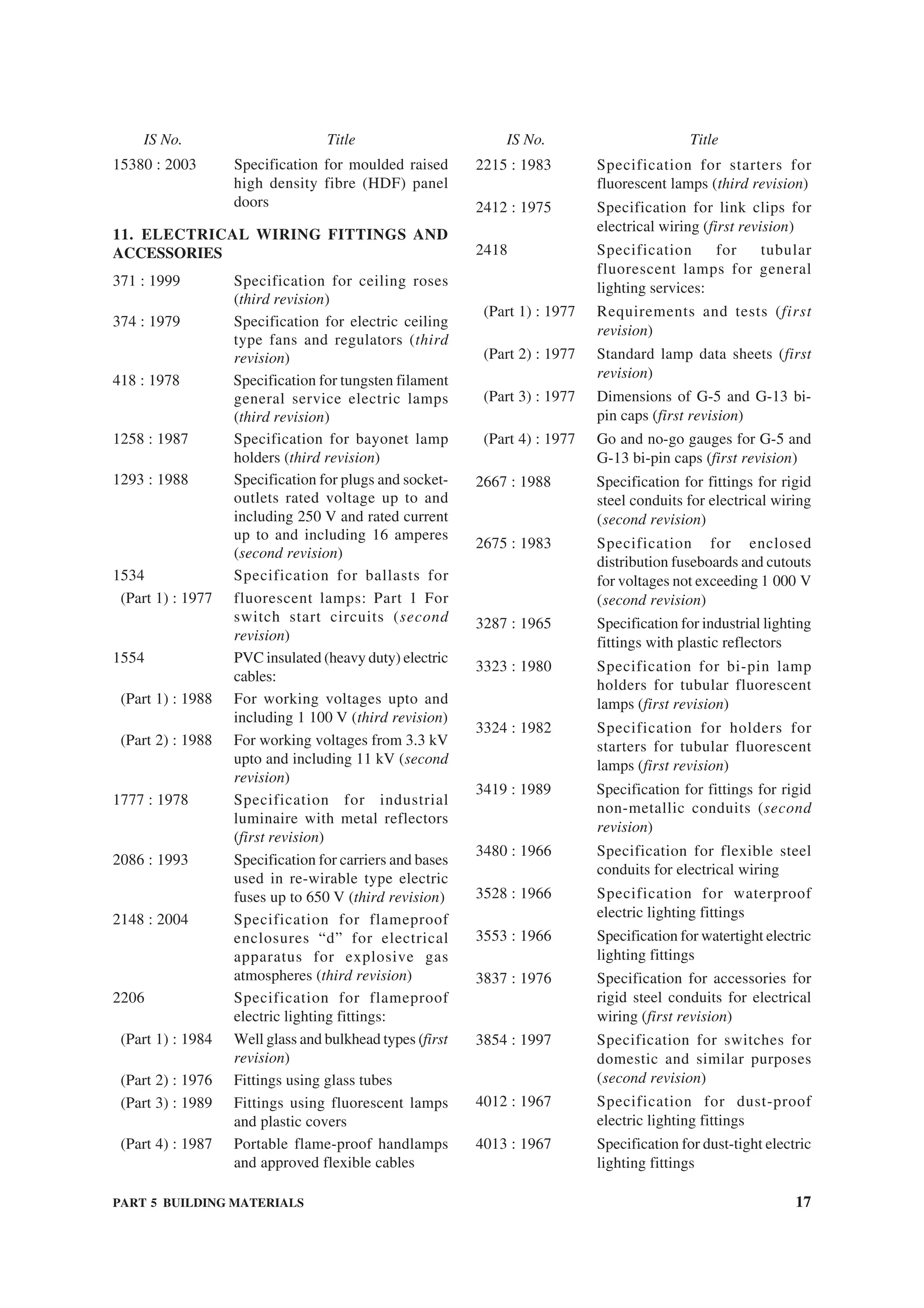
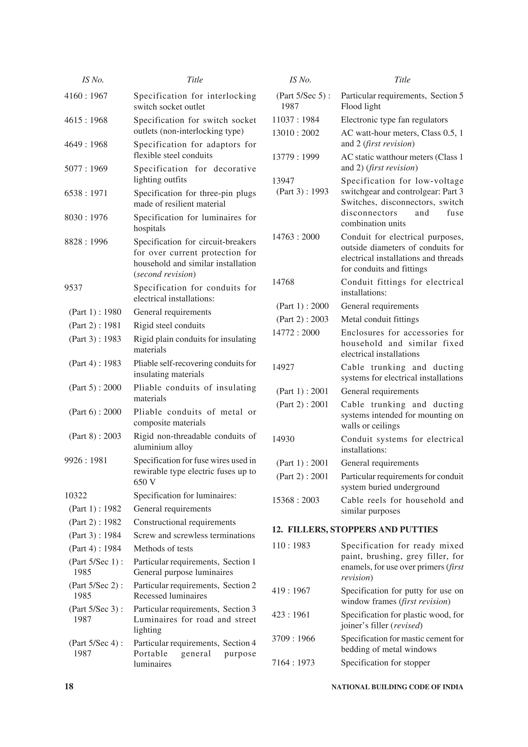
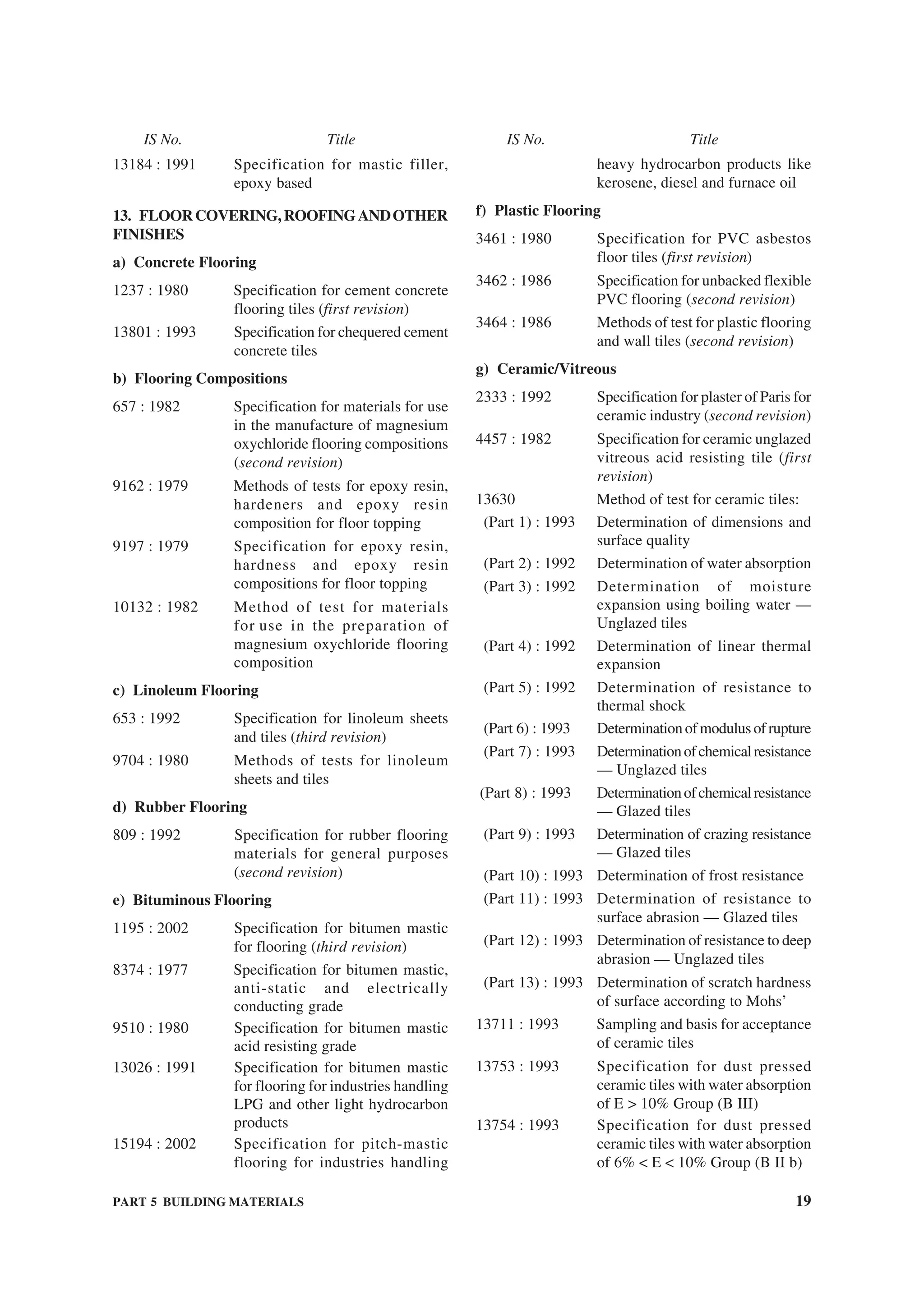
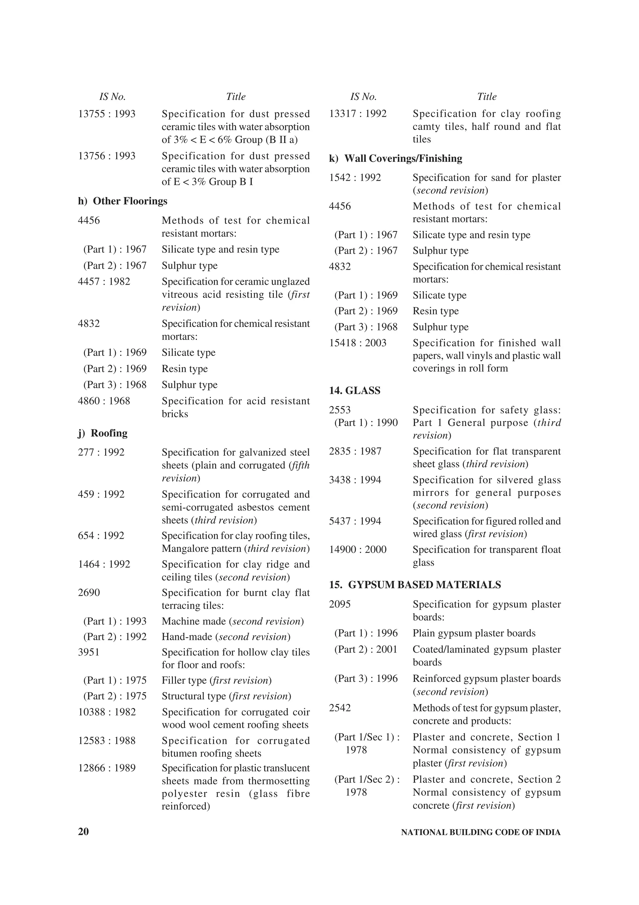
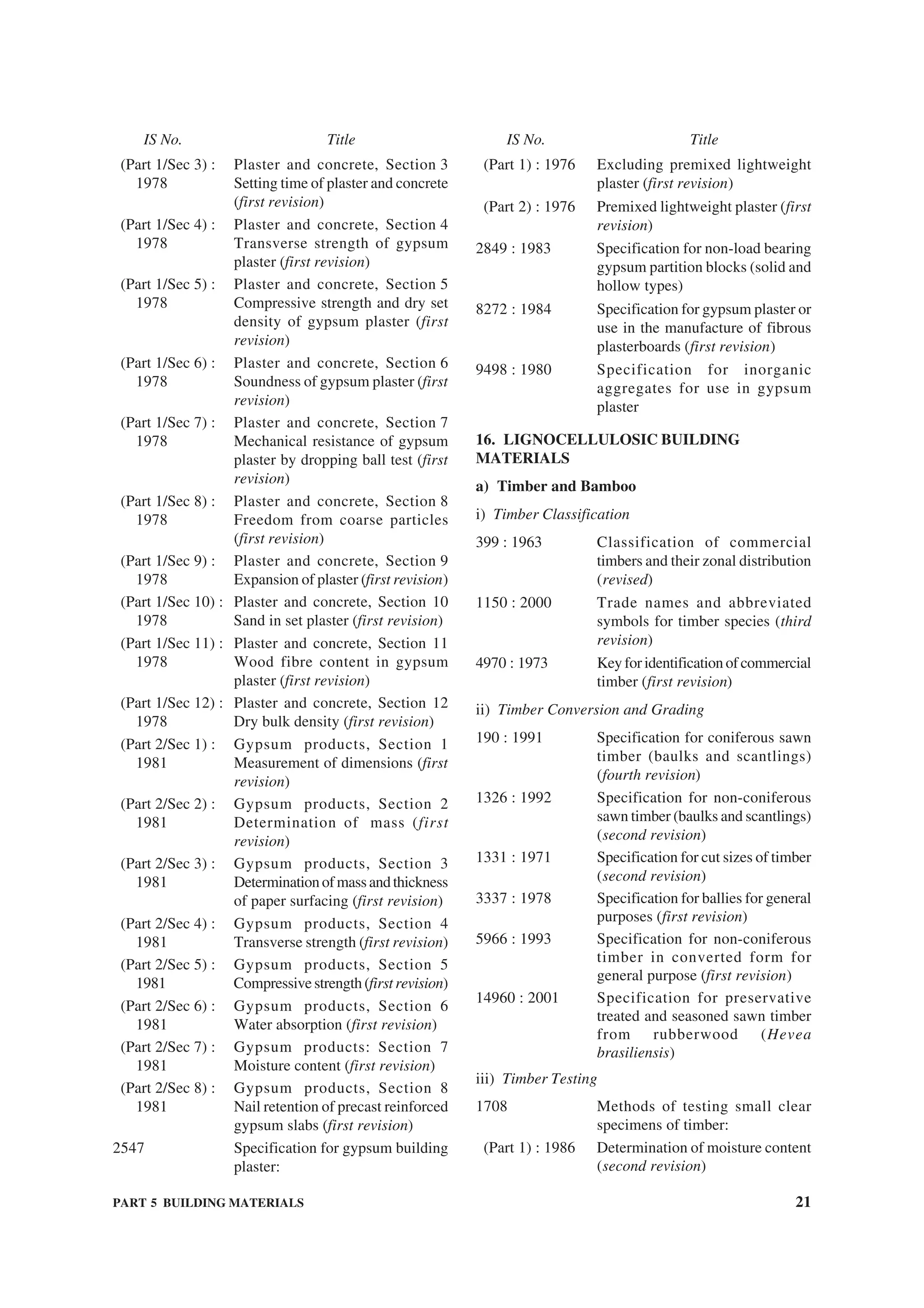
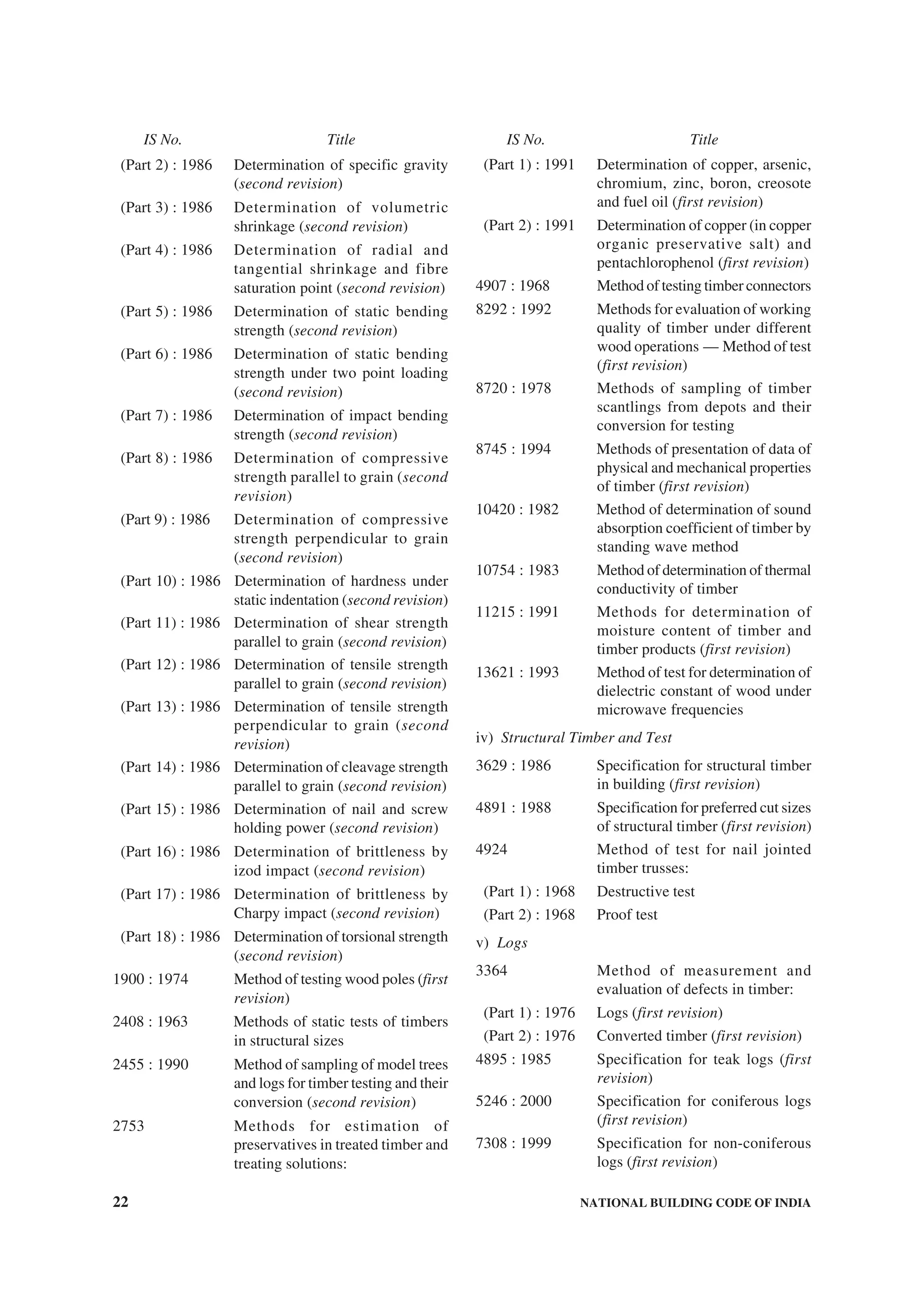
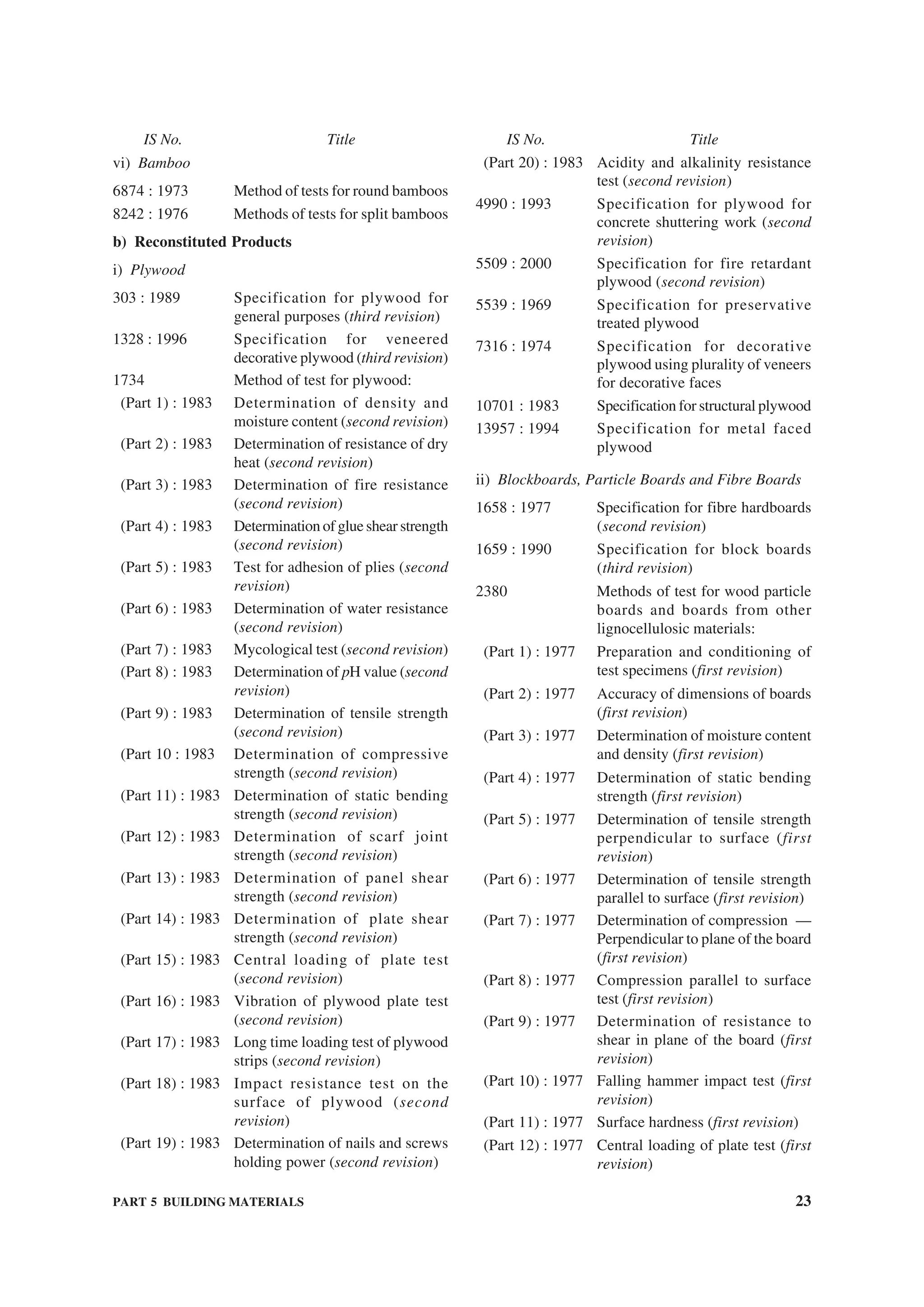
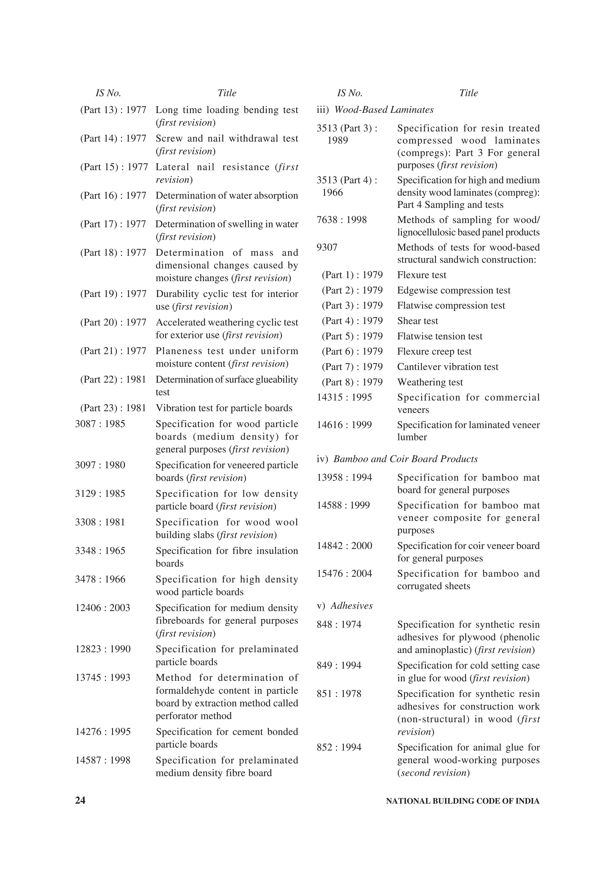
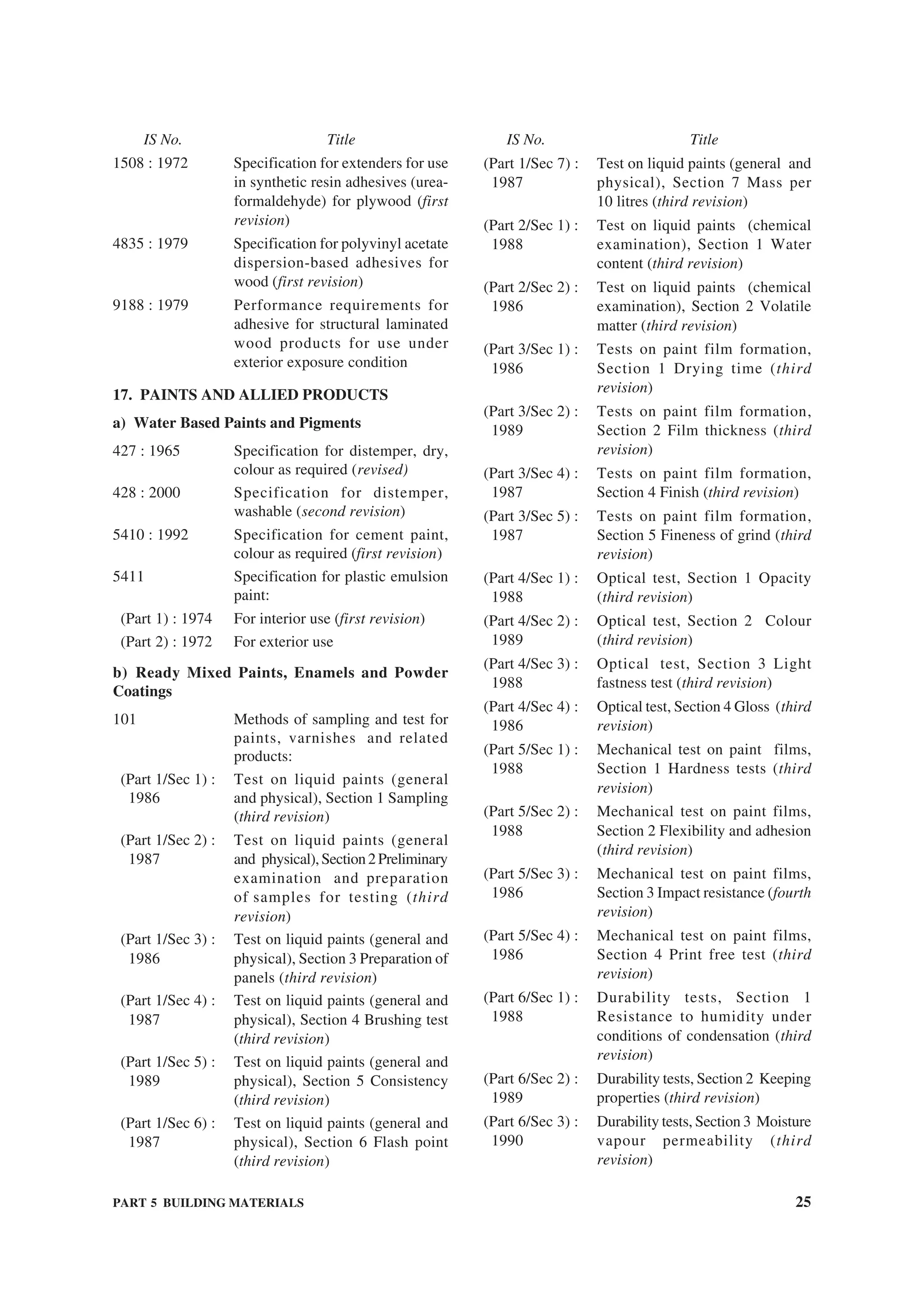
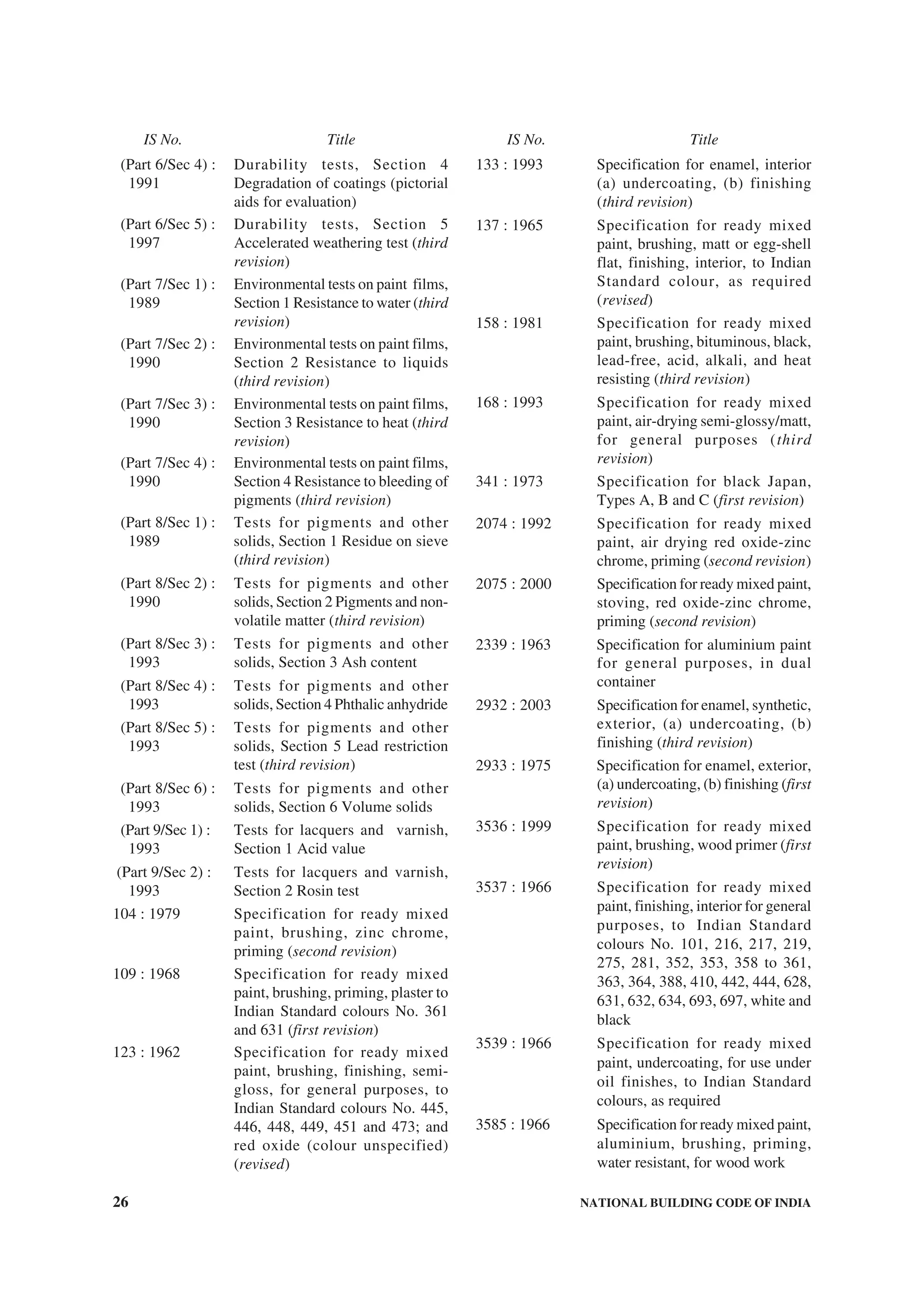
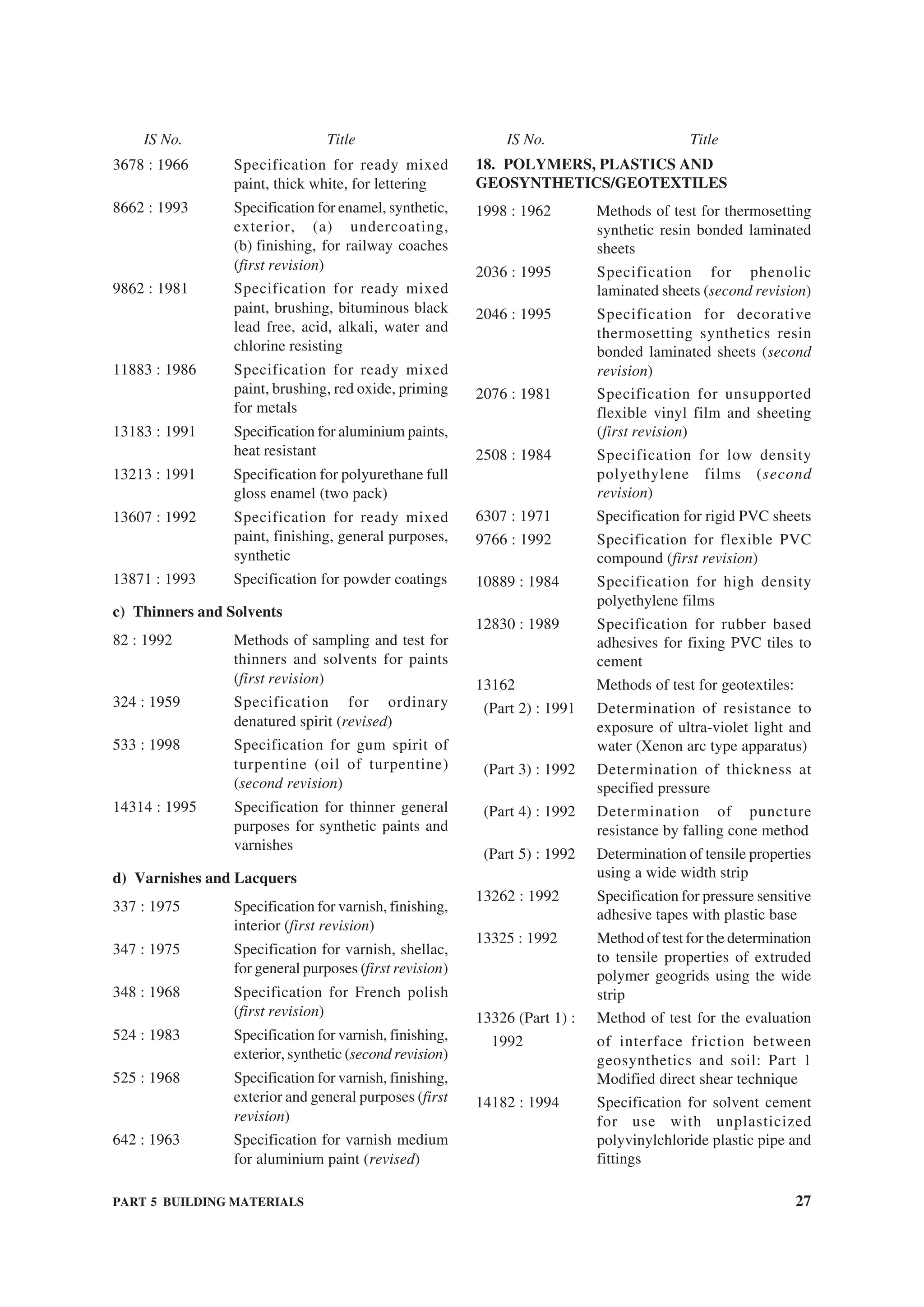
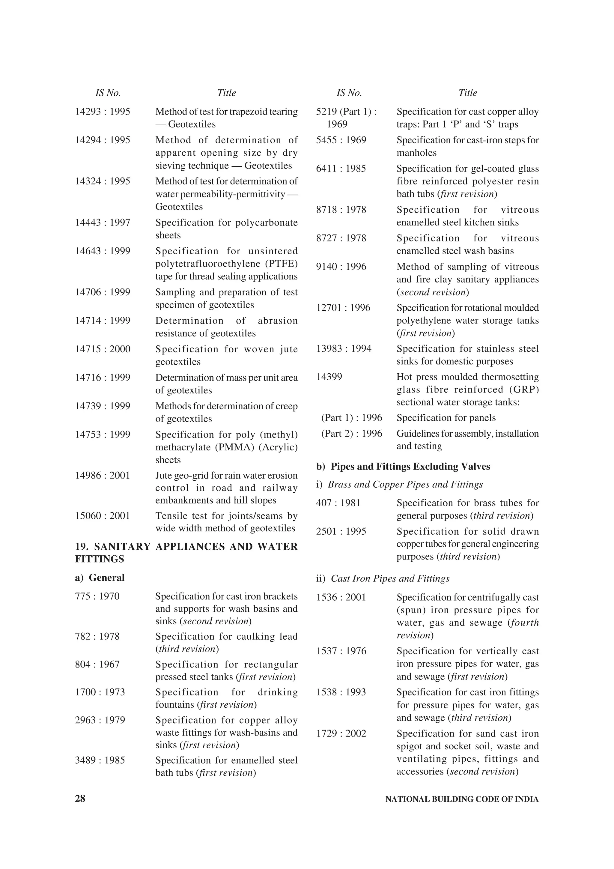
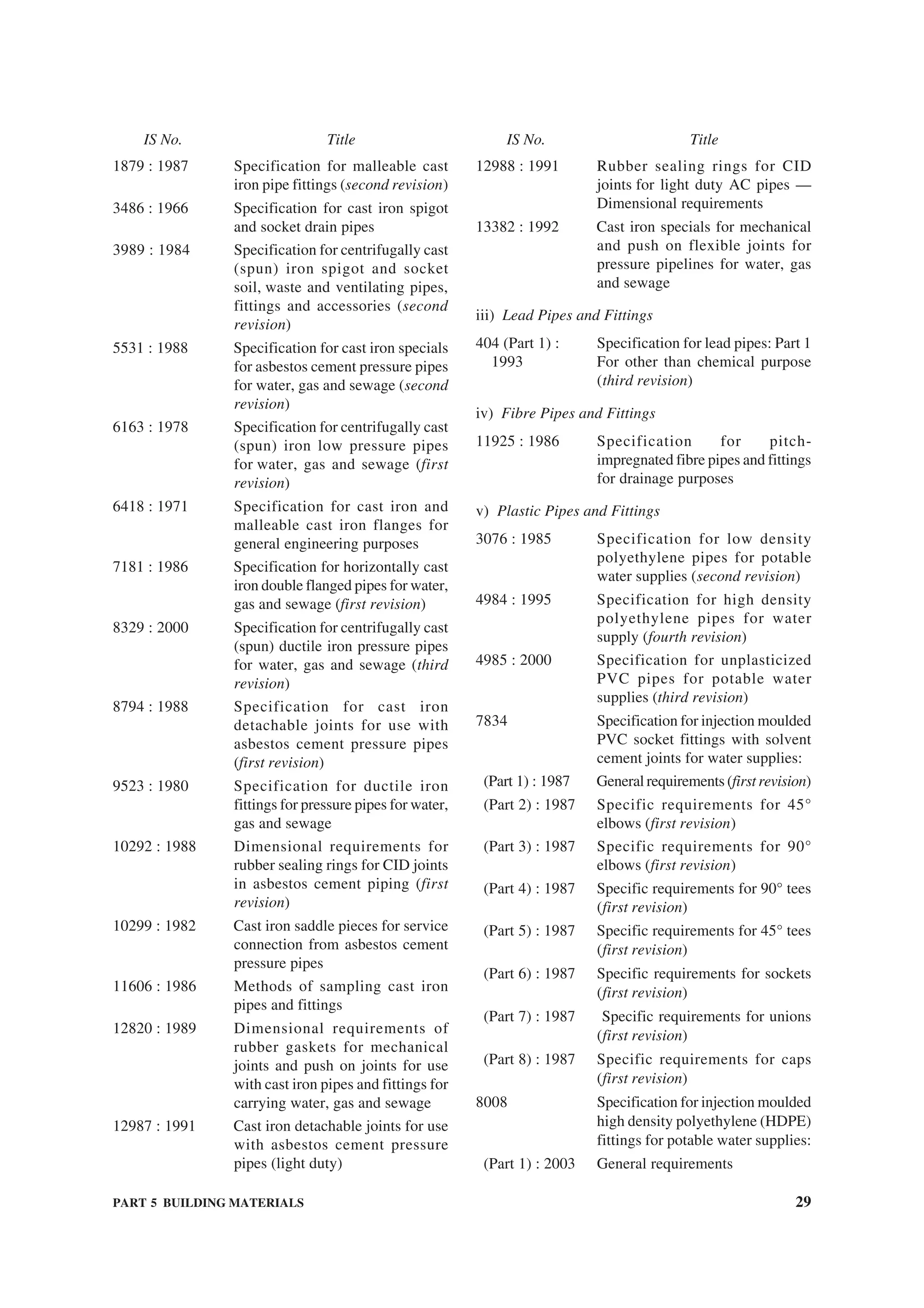
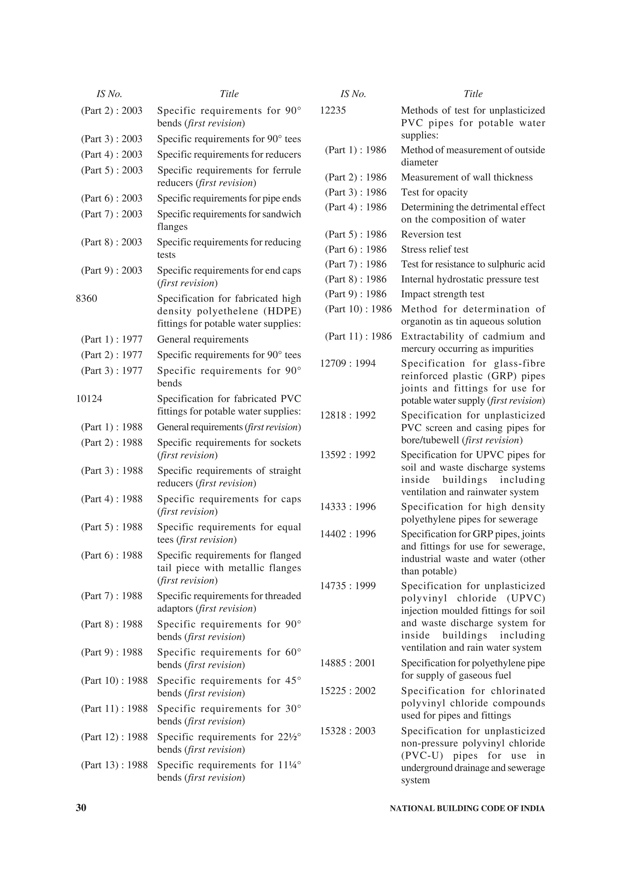
![PART 5 BUILDING MATERIALS 31
vi) Steel Tubes, Pipes and Fittings
1239 Mild steel tubes, tubular and other
wrought steel fittings:
(Part 1) : 1990 Mild steel tubes (fifth revision)
(Part 2) : 1992 Mild steel tubular and other
wrought steel pipe fittings (third
revision)
3589 : 1991 Specification for seamless or
electrically welded steel pipes for
water, gas and sewage (168.3 to
2 032 mm outside size) (second
revision)
4270 : 1992 Steel tubes used for water wells
(second revision)
5504 : 1997 Specification for spiral welded
pipes (first revision)
6286 : 1979 Seamless and welded steel pipe for
sub-zero temperature service
6392 : 1971 Steel pipe flanges
vii) Stoneware Pipes and Fittings
651 : 1992 Specification for salt-glazed
stoneware pipes and fittings (fifth
revision)
3006 : 1979 Specification for chemically
resistant glazed stoneware pipes
and fittings (first revision)
viii) Asbestos Cement Pipes
[See 8 (a) (ii) under the category ‘Composite Matrix
Products’]
ix) Concrete Pipes and Pipes Lined/Coated with
Concrete or Mortar
[See 8 (a) (iv) under the category ‘Composite Matrix
Products’]
c) Kitchen and Sanitary Appliances
771 Specification for glazed fire clay
sanitary appliances:
(Part 1) : 1979 General requirements (second
revision)
(Part 2) : 1985 Specific requirements of kitchen
and laboratory sinks (third revision)
(Part 3/Sec 1) : Specific requirements of urinals,
1979 Section 1 Slab urinals (second
revision)
(Part 3/Sec 2) : Part 3 Specific requirements of
1985 urinals, Section 2 Stall urinals
(third revision)
(Part 4) : 1979 Specific requirements of post
mortom slabs (second revision)
(Part 5) : 1979 Specific requirements of shower
trays (second revision)
(Part 6) : 1979 Specific requirements of bed-pan
sinks (second revision)
(Part 7) : 1981 Specific requirements of slop sinks
(second revision)
772 : 1973 Specification for general
requirements of enamelled cast
iron sanitary appliances (second
revision)
773 : 1988 Specification for enamelled cast
iron water-closets railway stock
type (fourth revision)
774 : 1984 Specification for flushing cisterns
for water-closets and urinals (other
thanplasticcisterns)(fourthrevision)
1726 : 1991 Specification for cast iron manhole
covers and frames (third revision)
2326 : 1987 Specification for automatic flushing
cisterns for urinals (second
revision)
2548 Specification for plastic seats and
covers for water-closets:
(Part 1) : 1996 Thermoset seats and covers (fifth
revision)
(Part 2) : 1996 Thermoplastic seats and covers
(fifth revision)
2556 Specification for vitreous sanitary
appliances (vitreous china):
(Part 1) : 1994 General requirements (third
revision)
(Part 2) : 1994 Specific requirements of wash-
down water-closets (fourth
revision)
(Part 3) : 1994 Specific requirements of squatting
pans (fourth revision)
(Part 4) : 1994 Specific requirements of wash
basins (third revision)
(Part 5) : 1994 Specific requirements of laboratory
sinks (third revision)
(Part 6) : 1995 Specific requirements of urinals
and partition plates (fourth revision)
(Part 7) : 1995 Specific requirements of accessories
for sanitary appliances (third
revision)
(Part 8) : 1995 Specific requirements of siphonic
wash-down water closets (fourth
revision)
IS No. Title IS No. Title](https://image.slidesharecdn.com/is-200203030013/75/NATIONAL-BUILDING-CODE-SP7-231-2048.jpg)
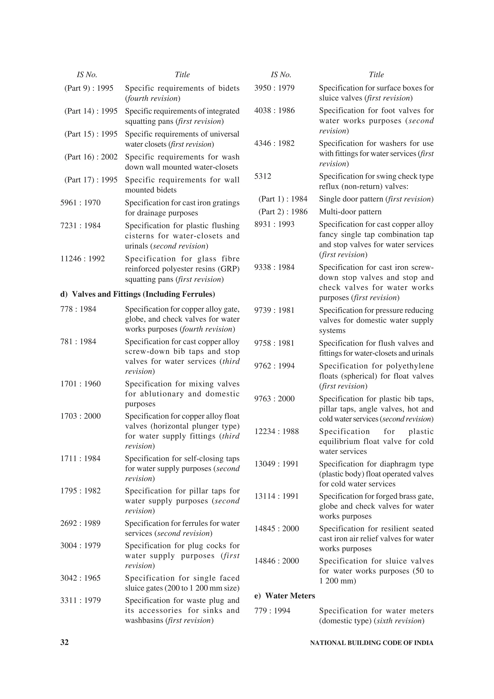
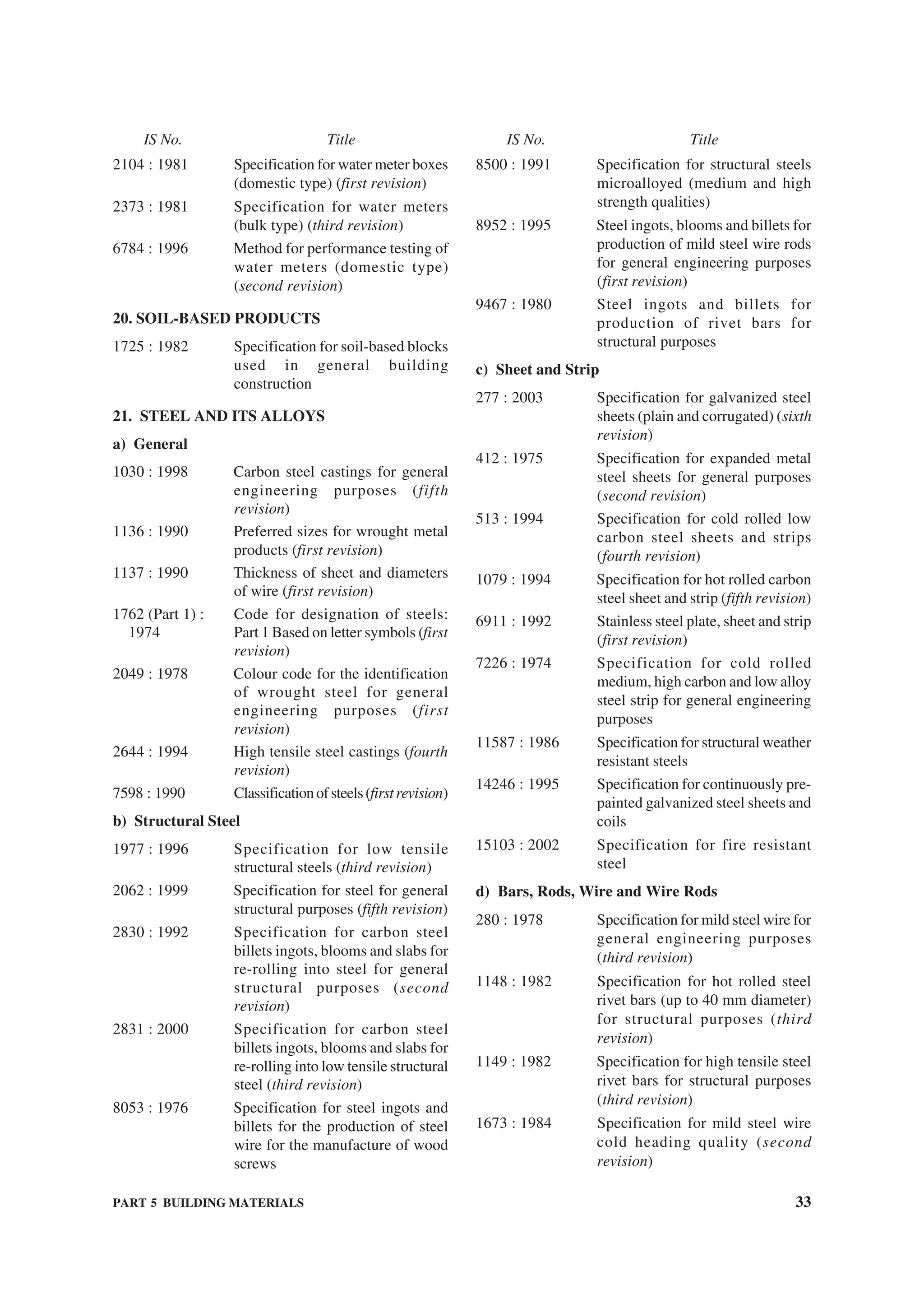
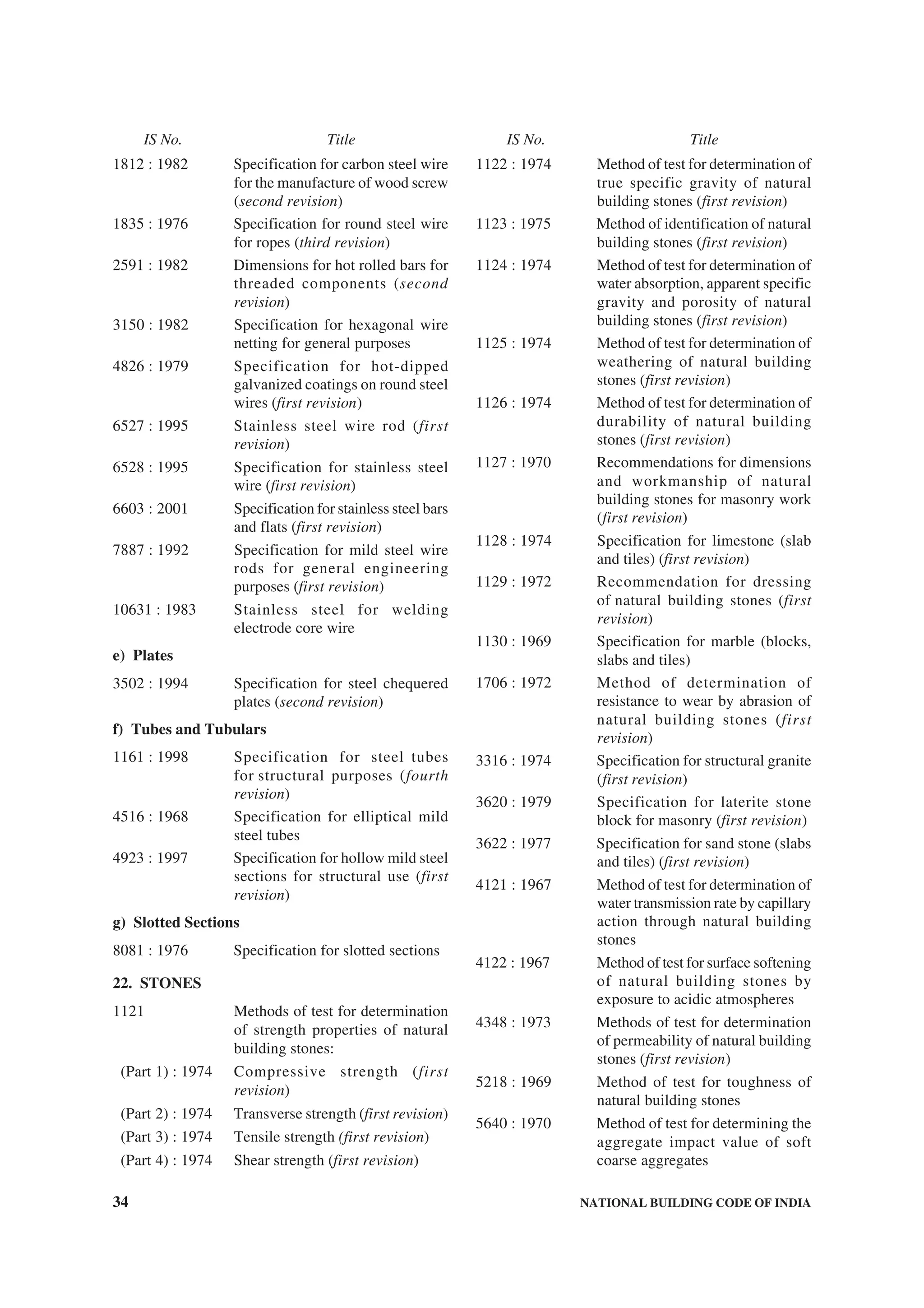
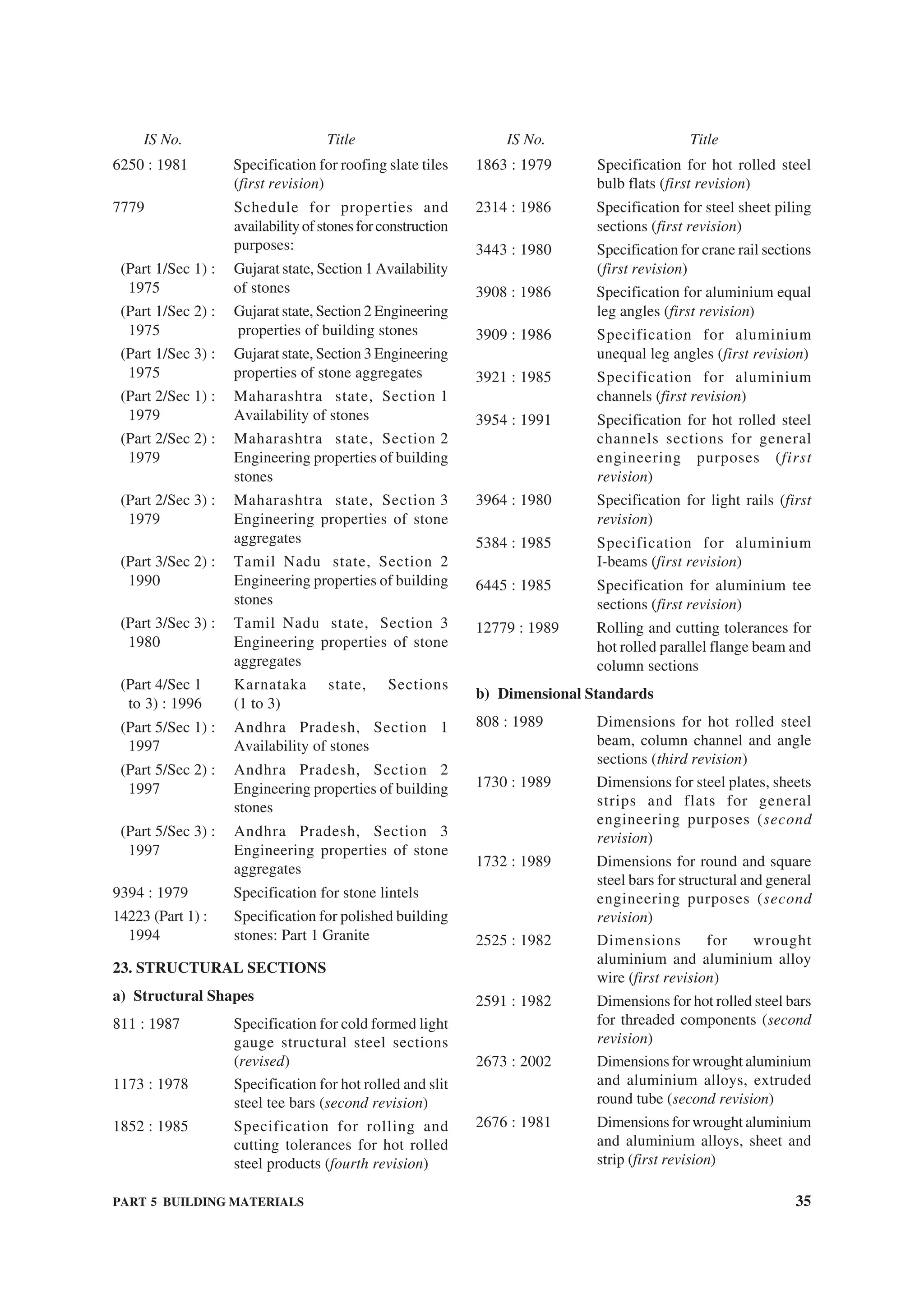
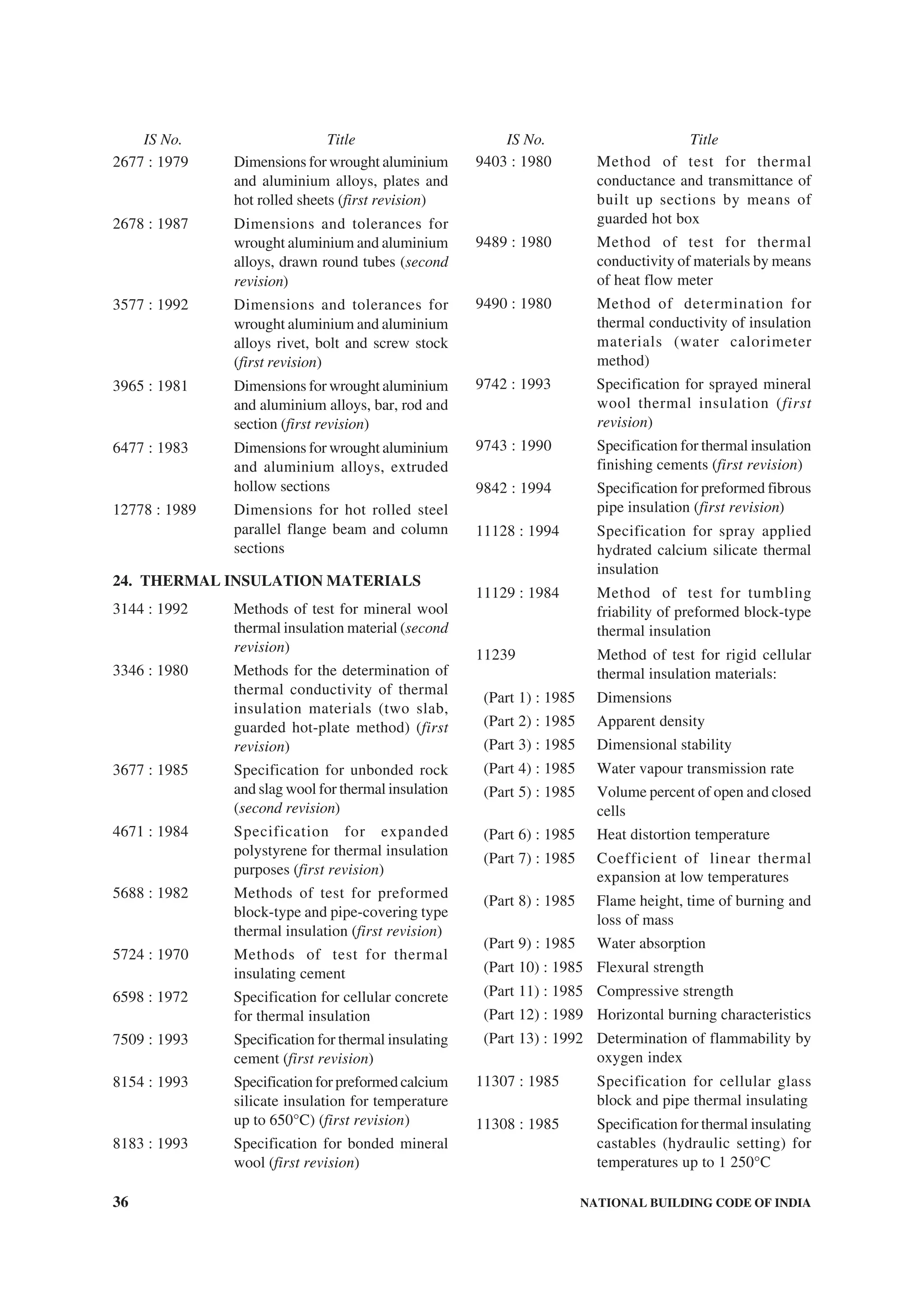
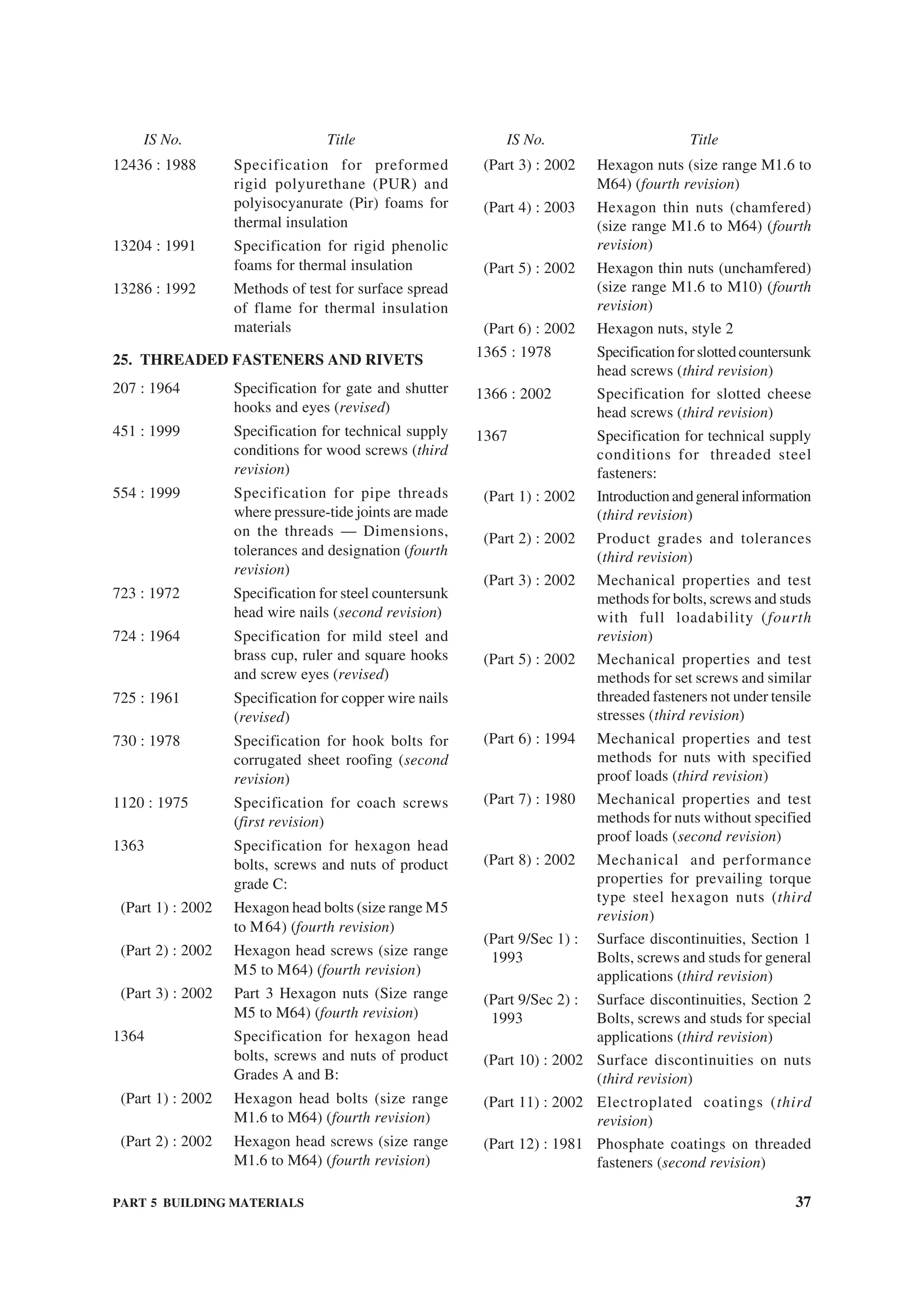
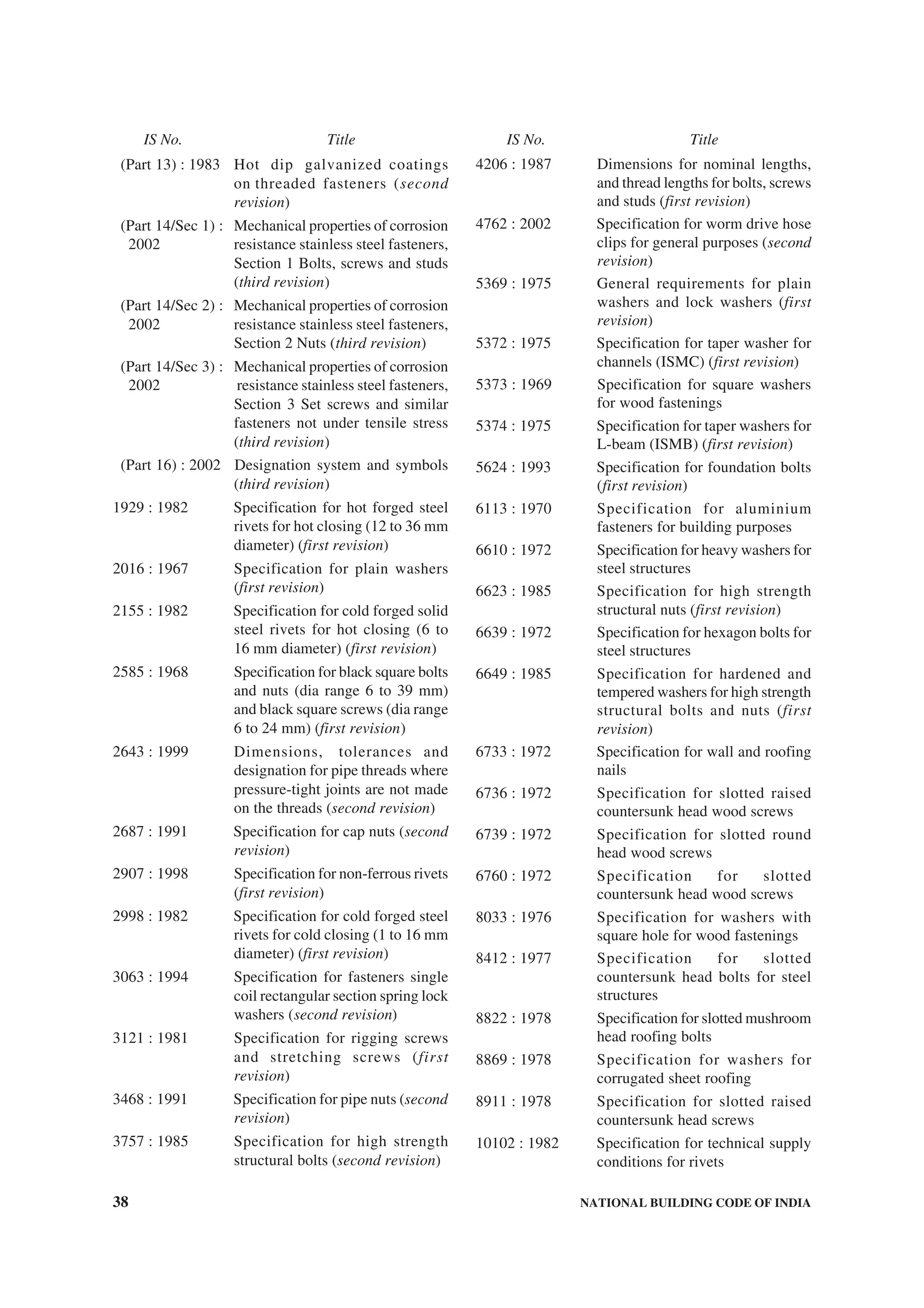
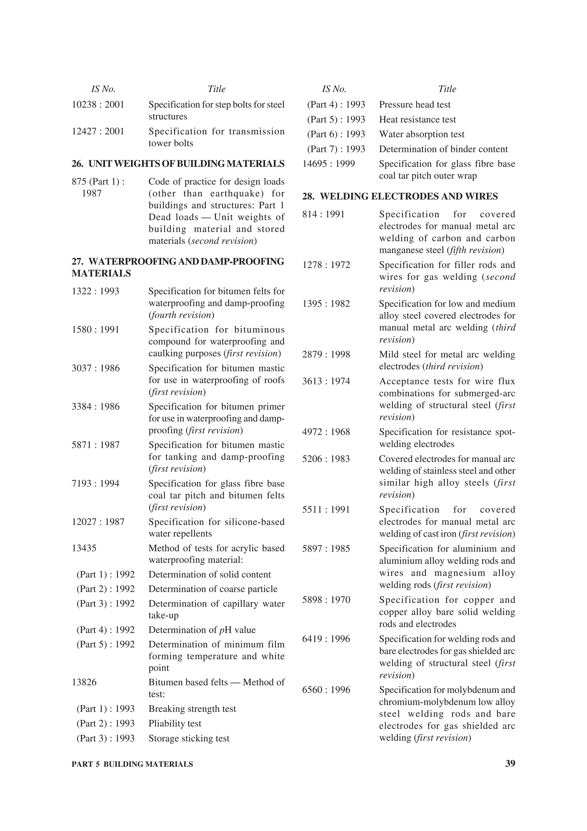
![PART 10 LANDSCAPING, SIGNS AND OUTDOOR DISPLAY STRUCTURES — SECTION 1 LANDSCAPE … 7
t) Refuse container location, size, and access.
u) Landscape paving materials with location.
v) Location, type, size, and height of existing
and proposed signage.
w) List of existing trees with botanical and
common names and height of the tree (see
4.1.2 for plant material schedule).
x) Prior approvals.
3.3 Landscape Plan Contents and Specifications
Landscape plan and drawings shall consist of the plans
and details as given in 3.3.1 to 3.3.4.
3.3.1 Grading Plan
The grading plan to be submitted with the application
for permit shall be drawn to a scale of not less than 1
in 500 for a site up to 10 hectare and not less than 1 in
1 000 for site more than 10 hectare (see also 6.2). The
grading plan will include measures for soil and
sedimentation control and also measures during
construction to prevent soil erosion, and also water
harvesting practices (see also 4 and 5).
3.3.2 Planting Plan
The planting plan shall be drawn to a scale of not less
than 1 in 200 for a site up to one hectare and not less
than 1 in 500 for site more than 10 hectare with part
plans at 1 in 200 of two of the design areas. Planting
plan should include plant material schedule as shown
in Table 1. The planting plan and landscape plan must
show identical information to avoid conflict between
both plans. The planting plan shall include the layouts
as given below drawn to the scale:
a) Location of proposed trees, shrubs, ground
covers and lawn area indicated clearly with
appropriate symbols and legend.
b) The size of plant material indicated in the
drawing should be shown as diameter of
canopy for tree and spread for shrubs and
ground cover. Two years growth will be
considered as full maturity size for shrubs and
ground covers and ten years growth will be
considered for trees.
c) The Botanical name could be indicated as a
symbol on the main drawing (for example
Delonix regia as Dr). Plant names should to
be tabulated in alphabetical order under heads
Trees, Shrubs, Groundcovers, Climbers and
Grass.
d) Functional attributes and growth pattern
tabulation to be attached as Table 2, as an
annex.
e) All existing vegetation shall be marked on the
landscape plan and areas designated for
preservation of existing vegetation on site
shall be demarcated clearly (see also 4.1.2).
f) A concept plan of scale not less than 1 in 1 000
indicating the intent of the design with respect
to the functions for various parts of the
scheme should be included.
Table 1 Plant Material Schedule
(Clause 3.3.2)
Tree
No.
Code Botanical
Name
Common
Name
Quantity
(1) (2) (3) (4) (5)
Table 2 Plant Material Schedule Showing
Functional Attributes and Growth
Pattern of Each Plant
[Clause 3.3.2 (d)]
Sl
No.
Relevant Features Description
Plant -1
(1) (2) (3)
i) Botanical name
ii) Common name
iii) Plant code
iv) Type (Evergreen/Deciduous)
v) Height
vi) Spread/Canopy
vii) Form of Tree
viii) Flower colour
ix) Seasonal duration
x) Zone (Functional Attributes)
xi) Characteristics
xii) Function
xiii) Remarks
3.3.3 Irrigation Plan
The irrigation plan shall be drawn to a scale of not less
than 1 in 500 for a site up to one hectare and not less
than 1 in 1 000 for site more than one hectare. The
Plan shall include the following information:
a) The source of irrigation water.
b) Type of water conserving irrigation systems
proposed differentiating between systems for
different water use zones on the site.
c) Extent of supplementary irrigation provided
by water harvesting measures.
d) Arrangement of hydrants or sprinklers
indicating location and type with typical
details and specifications.
3.3.4 Construction Details
Construction details, specifications and methods used
for the following landscape elements are to be included
where applicable:](https://image.slidesharecdn.com/is-200203030013/75/NATIONAL-BUILDING-CODE-SP7-246-2048.jpg)

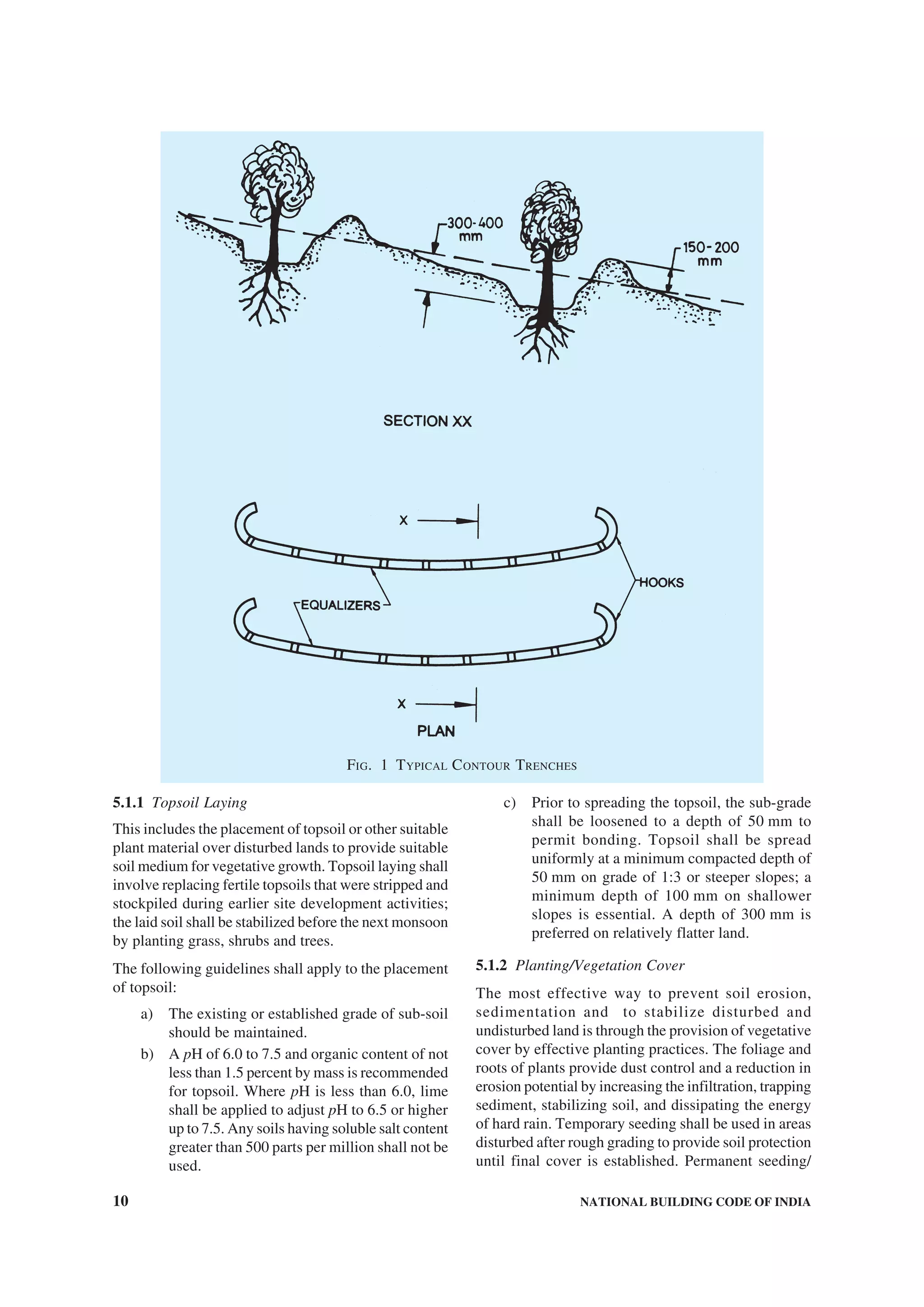
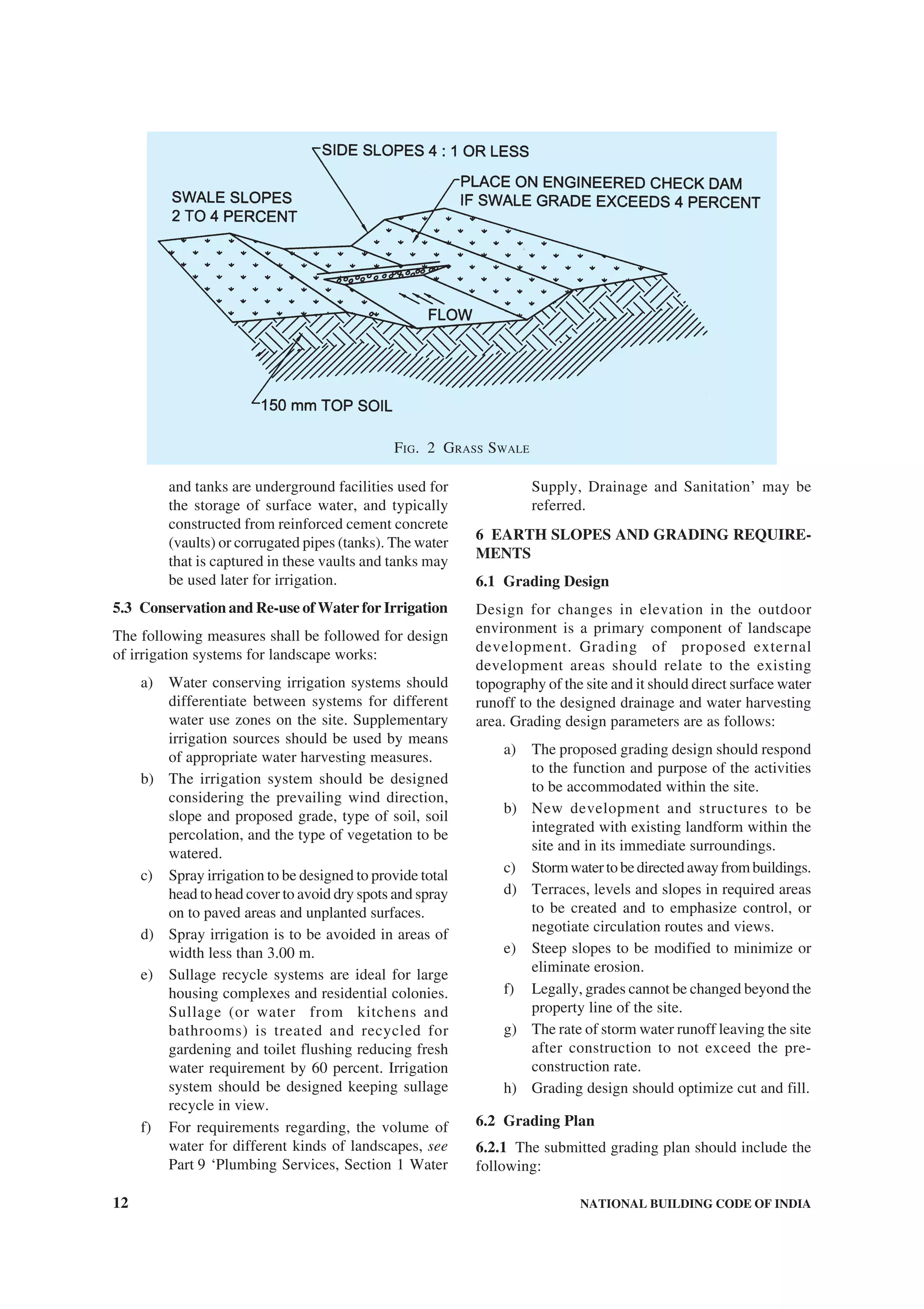
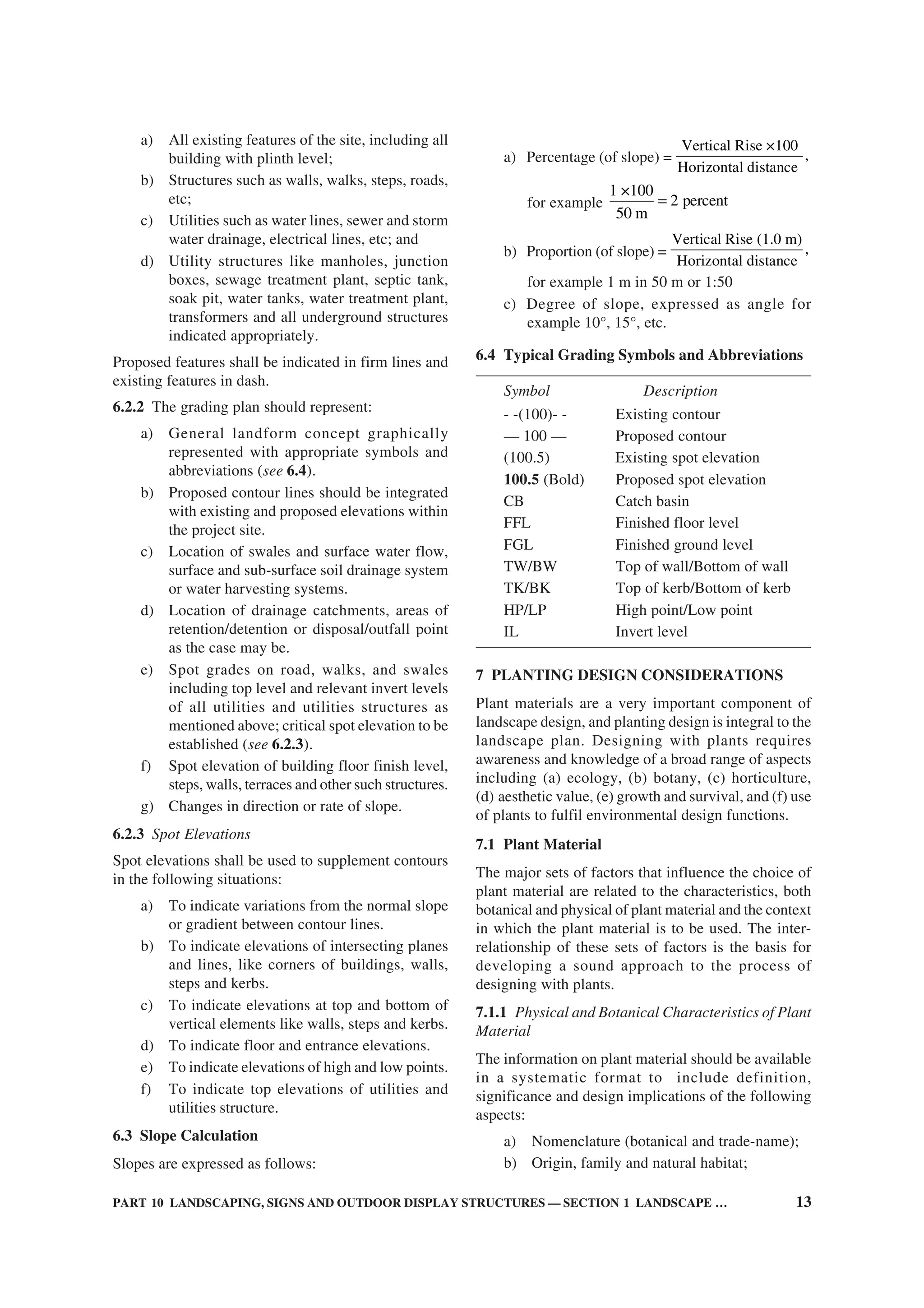
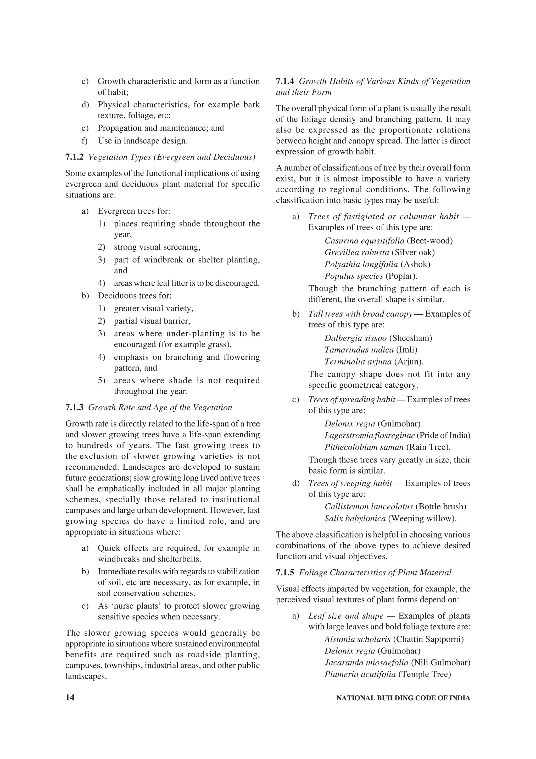
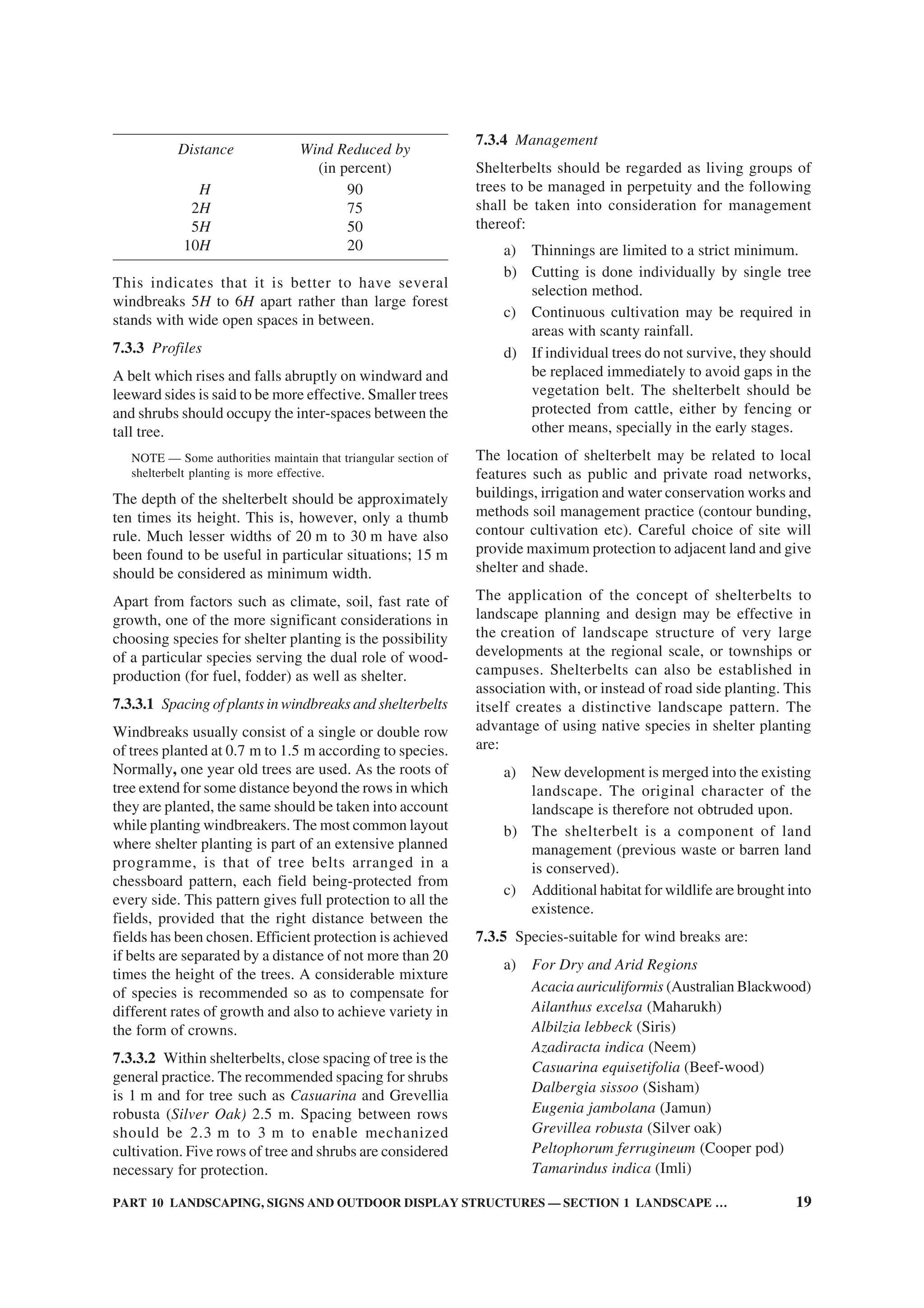
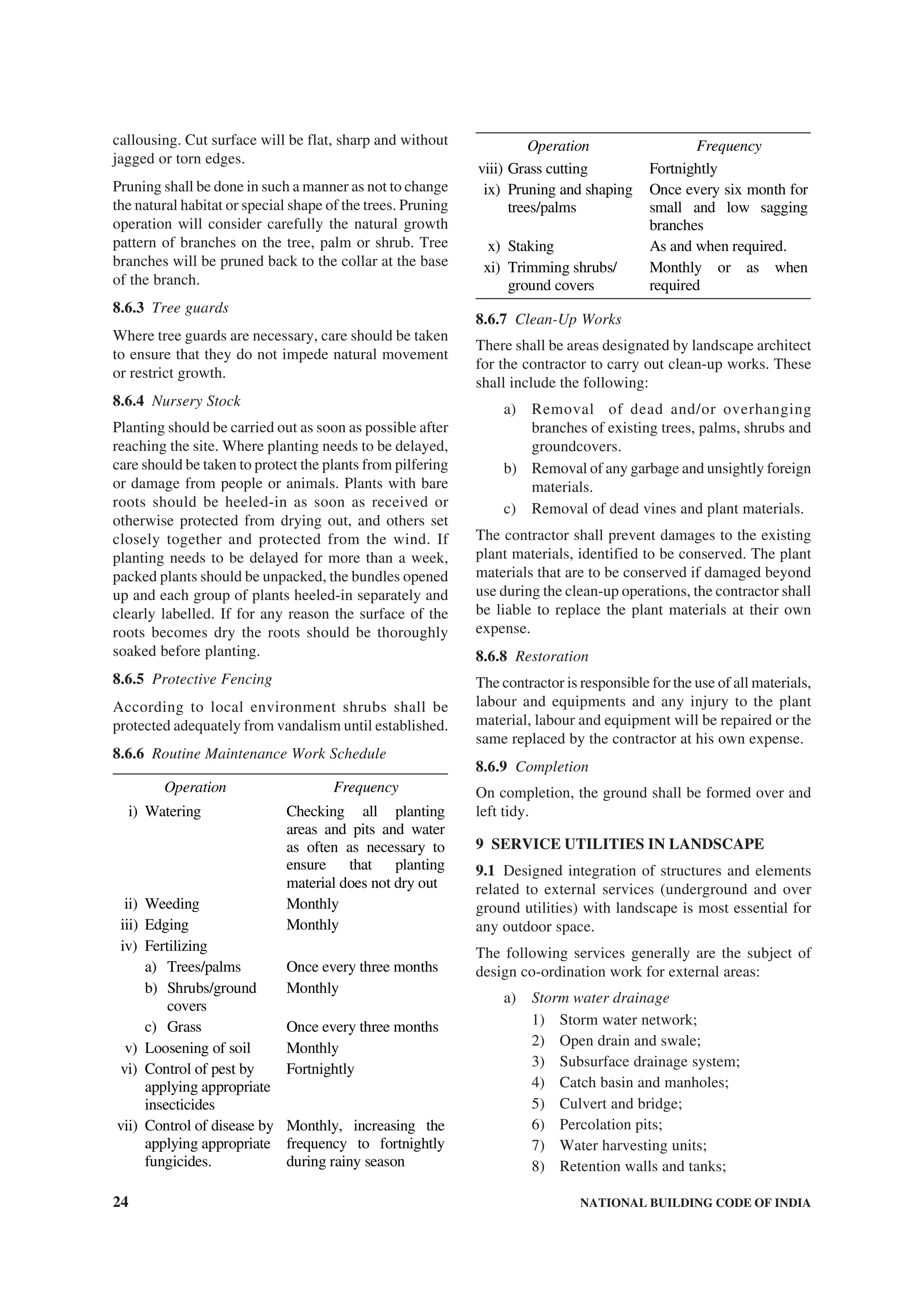
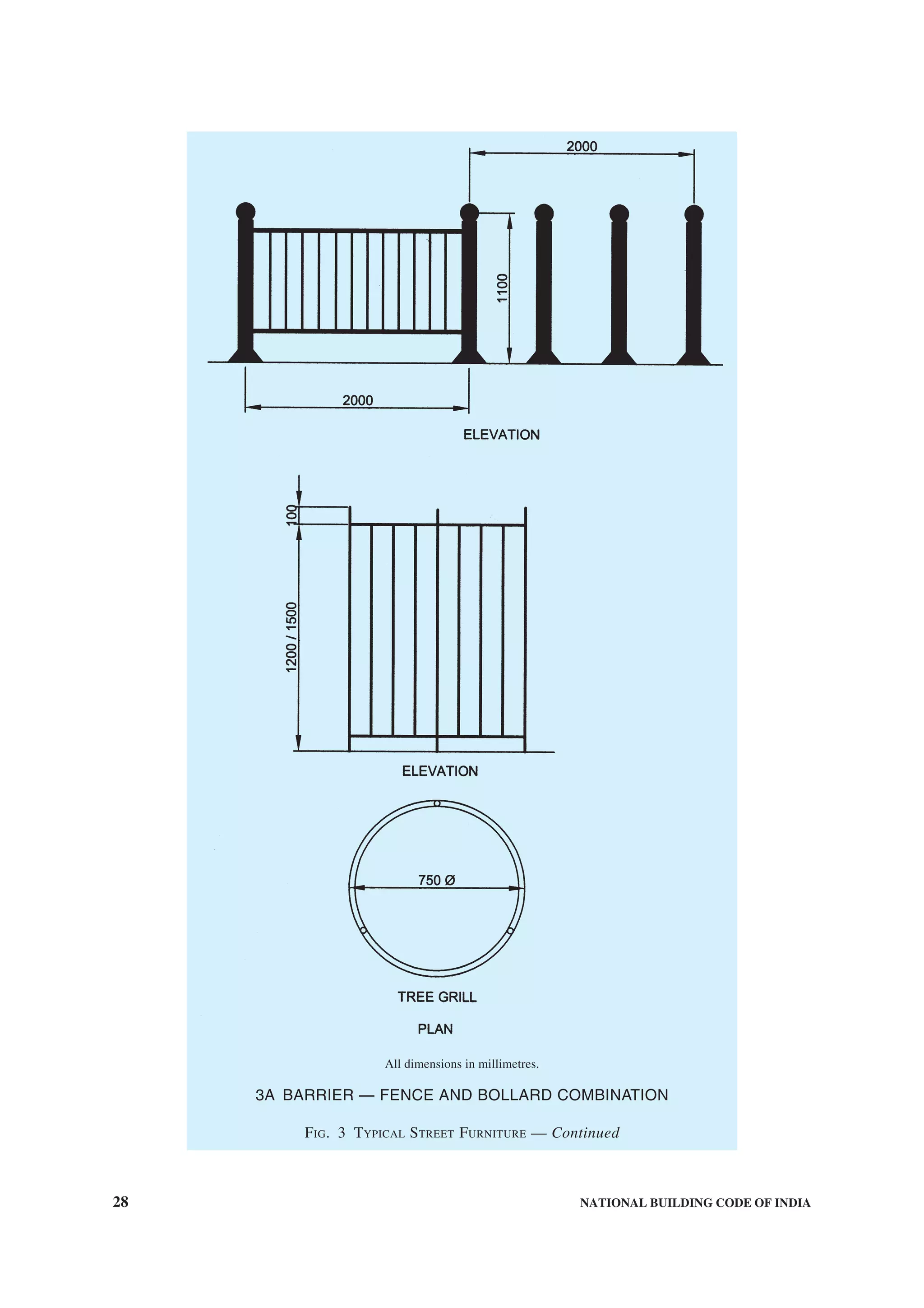
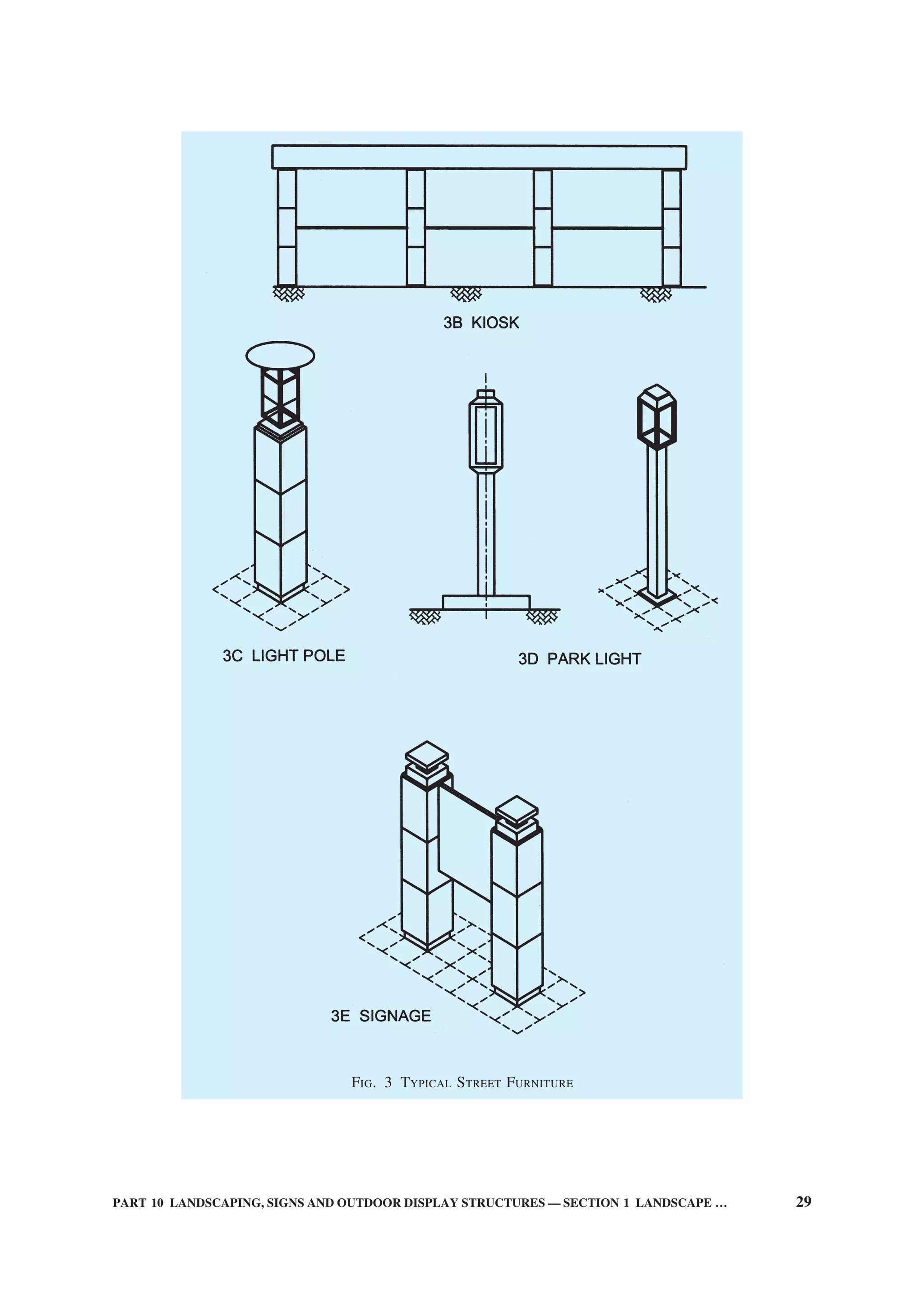
![6 NATIONAL BUILDING CODE OF INDIA
of a building including signs painted on the roof of a
building.
2.1.24 Sky Sign — An advertising sign displayed in
space like:
a) a gas filled balloon anchored to a point on
the ground and afloat in the air with or without
a streamer of cloth, etc; or
b) sky-writing, that is, a sign or word traced in
the atmosphere by smoke discharged from an
aeroplane.
2.1.25 Sign — Any device visible from a public place
that displays either commercial or non-commercial
messages by means of graphic presentation of
alphabetic or pictorial symbols or representations. Non-
commercial flags or any flags displayed from flagpoles
or staffs shall not be considered as signs.
2.1.26 Sign Area — The area of the smallest geometric
figure, or the sum of the combination of regular
geometric figures, which comprise the sign face. The
area of any double-sided or ‘V’ shaped sign shall be
the area of the largest single face only. The area of a
sphere shall be computed as the area of a circle. The
area of all other multiple-sided signs shall be computed
as 50 percent of the sum of the area of all faces of the
sign.
2.1.27 Sign Copy — Those letters, numerals, figures,
symbols, logos and graphic elements comprising the
content or message of a sign, exclusive of numerals
identifying a street address only.
2.1.28 Sign Face — The surface upon, against or
through which the sign copy is displayed or illustrated,
not including structural supports, architectural features
of a building or sign structure, non-structural or
decorative trim, or any areas that are separated from
the background surface upon which the sign copy is
displayed by a distinct delineation, such as a reveal or
border.
2.1.29 Sign Structure — Any structure supporting a
sign.
2.1.30 Temporary Sign — An advertising sign, banner
or other advertising device constructed of cloth, canvas,
fabric or any other light material, with or without a
structural frame, intended for a limited period of
display; including decorative displays for holidays or
public demonstrations.
2.1.31 VERANDAH Sign — An advertising sign
attached to, posted on or hung from a VERANDAH.
2.1.32 Wall Sign — An advertising sign, other than a
projecting sign, which is directly attached to or painted
or pasted on the exterior surface of or structural element
of any building.
2.1.33 Window Sign — A sign affixed to the surface
of a window with its message intended to be visible to
and readable from the public way or from adjacent
property.
2.2 General
2.2.1 Approved — Approved by the Authority having
jurisdiction.
2.2.2 Area of Special Control — Any area declared
an area of special control by the Authority in respect
of the display of advertising signs, where the
requirements for such display are more restrictive than
elsewhere in the area controlled by the Authority.
2.2.3 Authority Having Jurisdiction — The Authority
which has been created by a statute and which for the
purpose of administering the Code/Part, may authorize
a committee or an official to act on its behalf;
hereinafter called the ‘Authority’.
2.2.4 Building Line — The line up to which the plinth
of a building adjoining a street or an extension of a
street or on a future street may lawfully extend. It
includes the lines prescribed, if any, in any scheme.
2.2.5 CombustibleMaterial—Amaterialiscombustible,
if it burns or adds heat to a fire when tested for non-
combustibility in accordance with good practice
[10-2(1)].
2.2.6 Owner — Person or body having a legal interest
in land and/or building thereon. This includes free
holders, leaseholders or those holding a sub-lease
which both bestows a legal right to occupation and
gives rise to liabilities in respect of safety or building
condition.
In case of lease or sublease holders, as far as ownership
with respect to the structure is concerned, the structure
of a flat or structure on a plot belongs to the allottee/
lessee till the allotment/lease subsists.
2.2.7 Street Line — The line defining the side limits
of a street.
3 PERMITS
3.1 Application
3.1.1 Conditions for Grant of Permit
No sign shall be erected, altered or maintained without
first obtaining a permit for the same from the Authority
and shall be subjected to the following conditions:
a) The written permission shall not be granted
or renewed at any one time, for a period
exceeding three years from the date of grant
of such permission or renewal.
b) The written permission or the renewal granted
by the Authority shall become void:](https://image.slidesharecdn.com/is-200203030013/75/NATIONAL-BUILDING-CODE-SP7-273-2048.jpg)
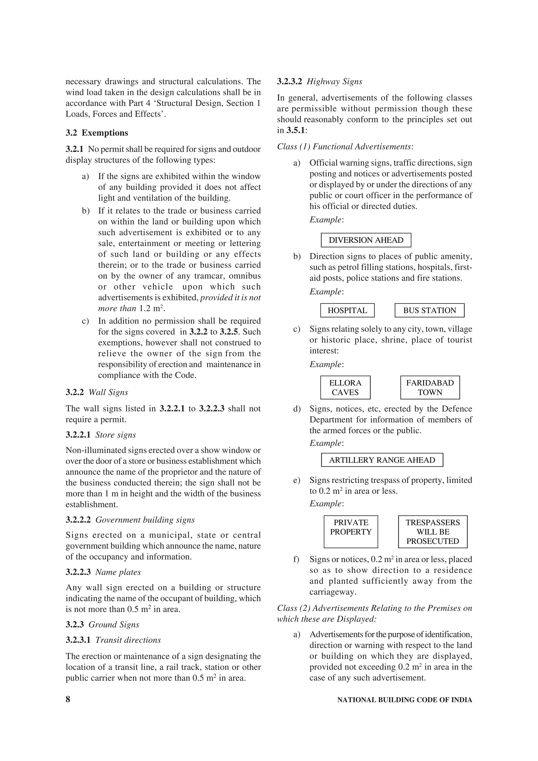
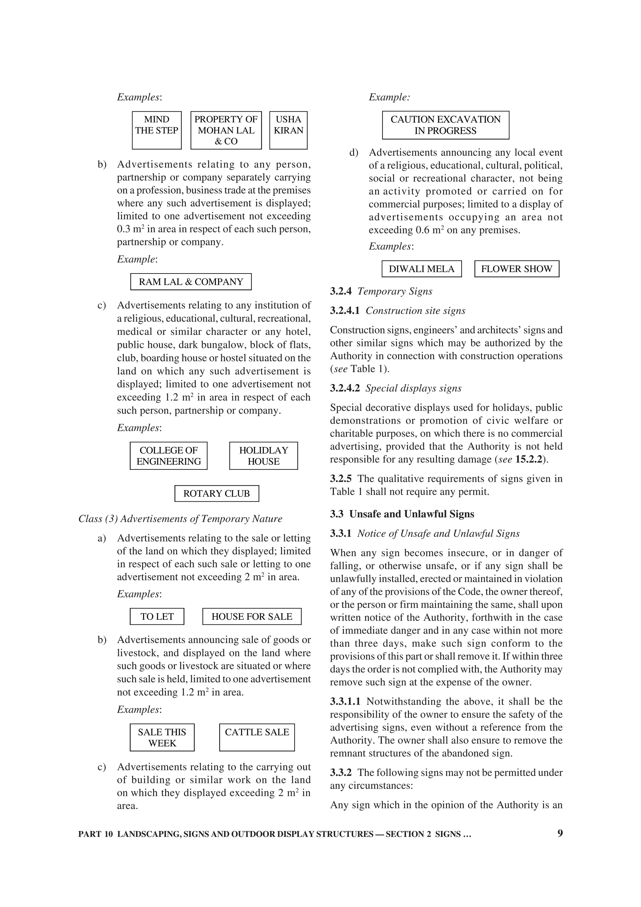
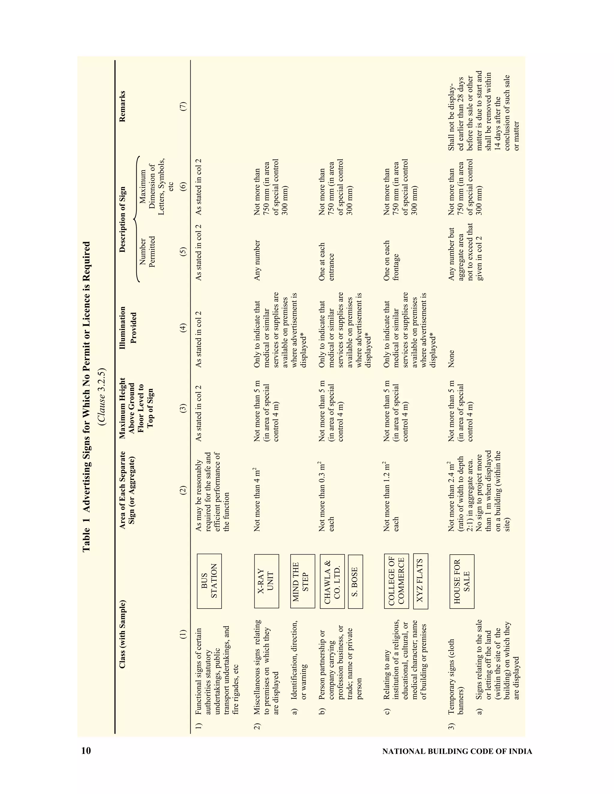
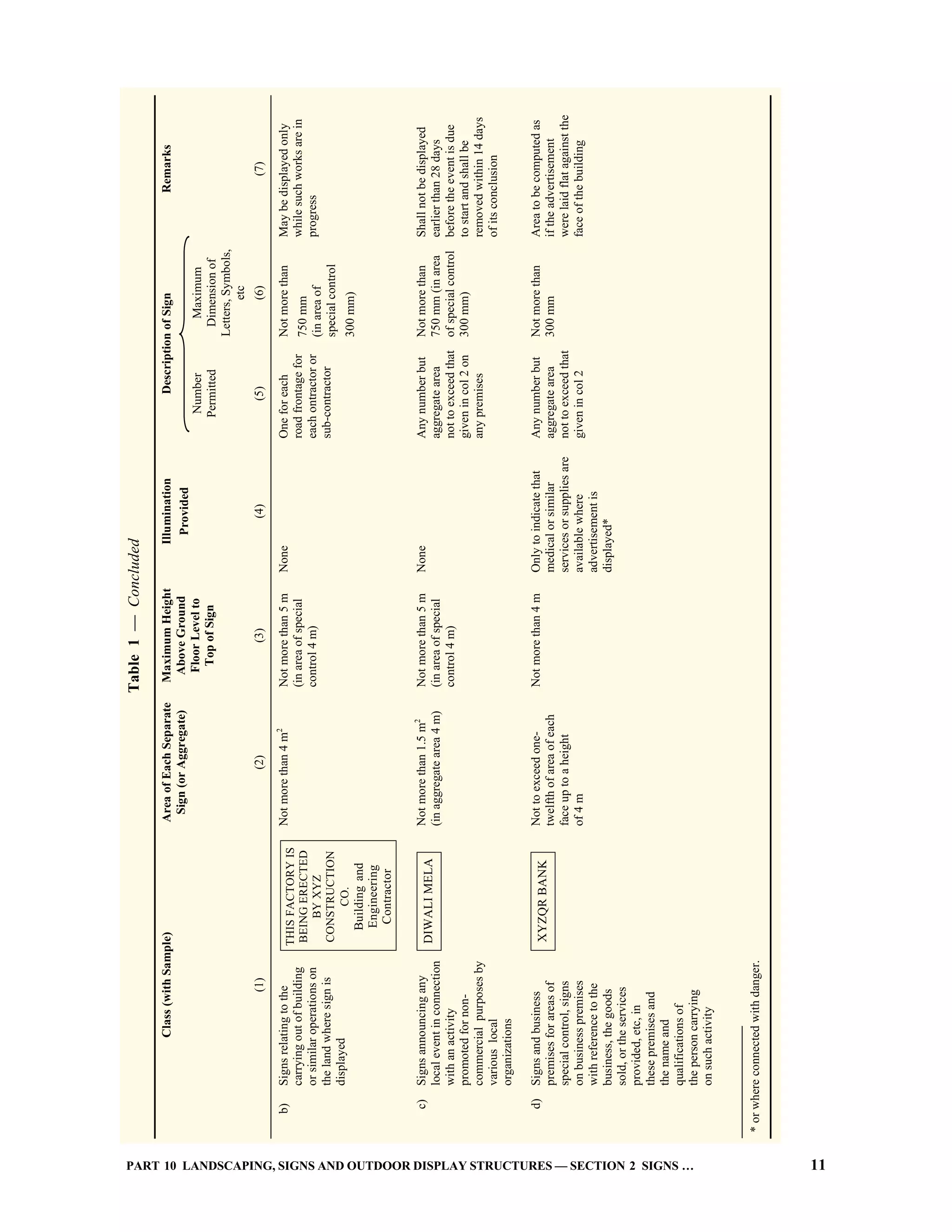
![PART 10 LANDSCAPING, SIGNS AND OUTDOOR DISPLAY STRUCTURES — SECTION 2 SIGNS … 13
illuminated by any flashing, intermittent or
moving light or lights except those giving
public service information, such as time,
temperature, weather or date;
b) Illuminated advertisements of such intensity
or brilliance as to cause glare or impair vision
of the driver or pedestrians, or which
otherwise interfere with any operations of
driving; and
c) Advertisements illuminated in such a way as
to obscure or diminish effectiveness of any
official sign, device or signal.
4 MAINTENANCE AND INSPECTION
4.1 Maintenance
All signs for which a permit is required, together with
all their supports, braces, guys and anchors shall be
kept in good repair, both structurally and aesthetically,
and when not galvanized or constructed of approved
corrosion-resistive non-combustible materials, shall be
painted when necessary to prevent corrosion.
4.2 Housekeeping
It shall be the duty and responsibility of the owner of
every sign to maintain the immediate premises occupied
by the sign, in a clean, sanitary and healthy condition.
4.3 Inspection
Every sign for which a permit has been issued and
every existing sign for which a permit is required shall
be inspected by the Authority at least once in every
calendar year.
5 TYPES OF SIGNS
In this part, the following types of signs are covered
[see also a few explanatory figures of general sign types
(Fig. 1A), comparison of roof and wall or fascia sign
(Fig. 1B) and sign area computation methodology
(Fig. 1C and 1D)].
a) Electric and illuminated signs (see 7);
b) Ground signs (see 8);
c) Roof signs (see 9);
d) VERANDAH signs (see 10);
e) Wall signs (see 11);
f) Projecting signs (see 12);
g) Marquee signs (see 13);
h) Sky signs (see 14); and
j) Miscellaneous and temporary signs (see 15).
6 GENERAL REQUIREMENTS FOR ALLSIGNS
6.1 Loads
Every advertising sign shall be designed so as to
withstand safely the wind, dead, seismic and other
loads as set out in Part 6 ‘Structural Design, Section 1
Loads, Forces and Effects’.
6.2 Illumination
No sign shall be illuminated by other than electrical
means and electrical devices and wiring shall be
installed in accordance with the requirements of Part 8
‘Building Services, Section 2 Electrical and Allied
Installations’. In no case, shall any open spark or flame
be used for display purposes unless specifically
approved by the Authority.
6.3 Design and Location of Advertising Signs
a) Sign should not obstruct any pedestrian
movement, fire escape, door or window,
opening used as a means for egress or fire
fighting purposes.
b) No sign shall in any form or manner interfere
with openings required for light and
ventilation.
c) When possible signs should be gathered
together into unified systems. Sign clutter
should be avoided in the landscape.
d) Signs should be combined with lighting
fixture to reduce unnecessary posts and for
ease of illuminating the signs.
e) Information signs should be placed at natural
gathering spots and included in the design of
sight furniture.
f) Placement of sign should be avoided where
they may conflict with pedestrian traffic.
g) Sign should be placed to allow safe pedestrian
clearance vertically and latterly.
h) Braille strips may be placed along sign edges
or raised letters may be used for readability
for the blind and partially sighted.
j) No sign shall be attached in anyway to a tree
or shrub.
6.4 Use of Combustibles
6.4.1 Ornamental Features
Wood or plastic or other materials of combustible
characteristics similar to wood may be used for
mouldings, cappings, nailing blocks, letters and
latticing where permitted and for other purely
ornamental features of signs.
6.4.2 Sign Facings
Sign facings may be made of approved combustible
materials provided the area of each face is not more
than 10 m2
and the wiring for electric lighting is entirely
enclosed in metal conduit and installed with a clearance
of not less than 5 cm from the facing material.](https://image.slidesharecdn.com/is-200203030013/75/NATIONAL-BUILDING-CODE-SP7-280-2048.jpg)
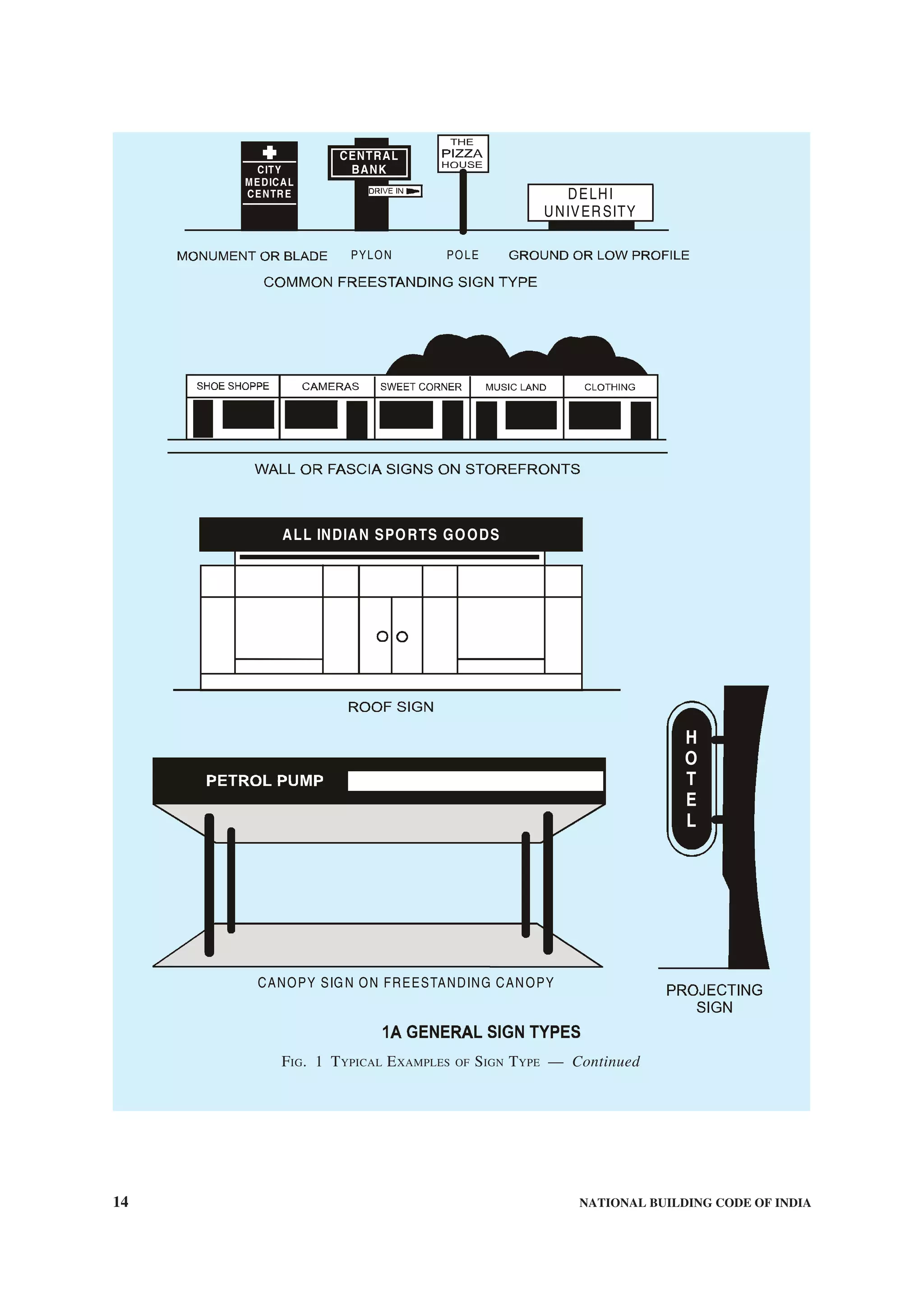
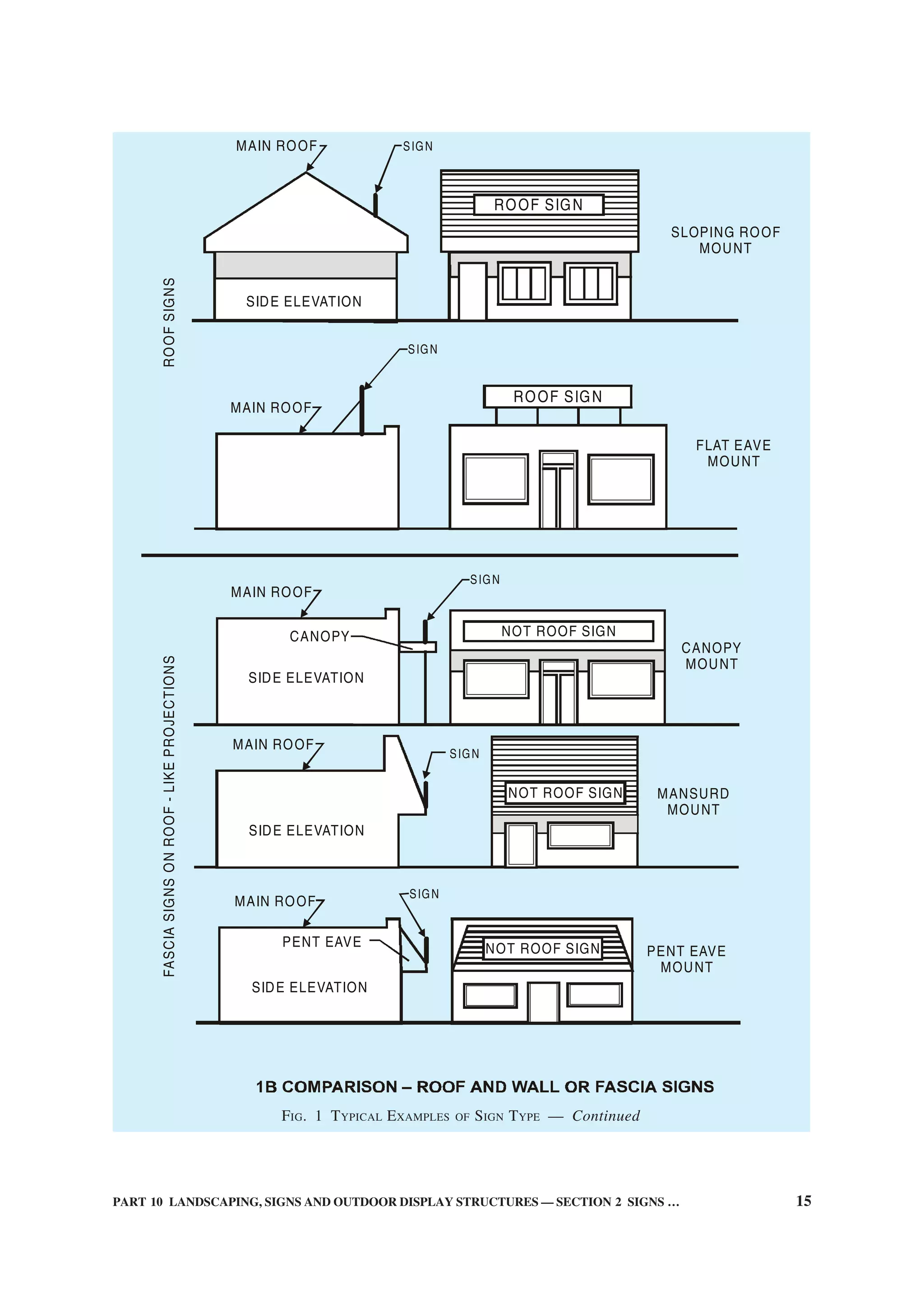
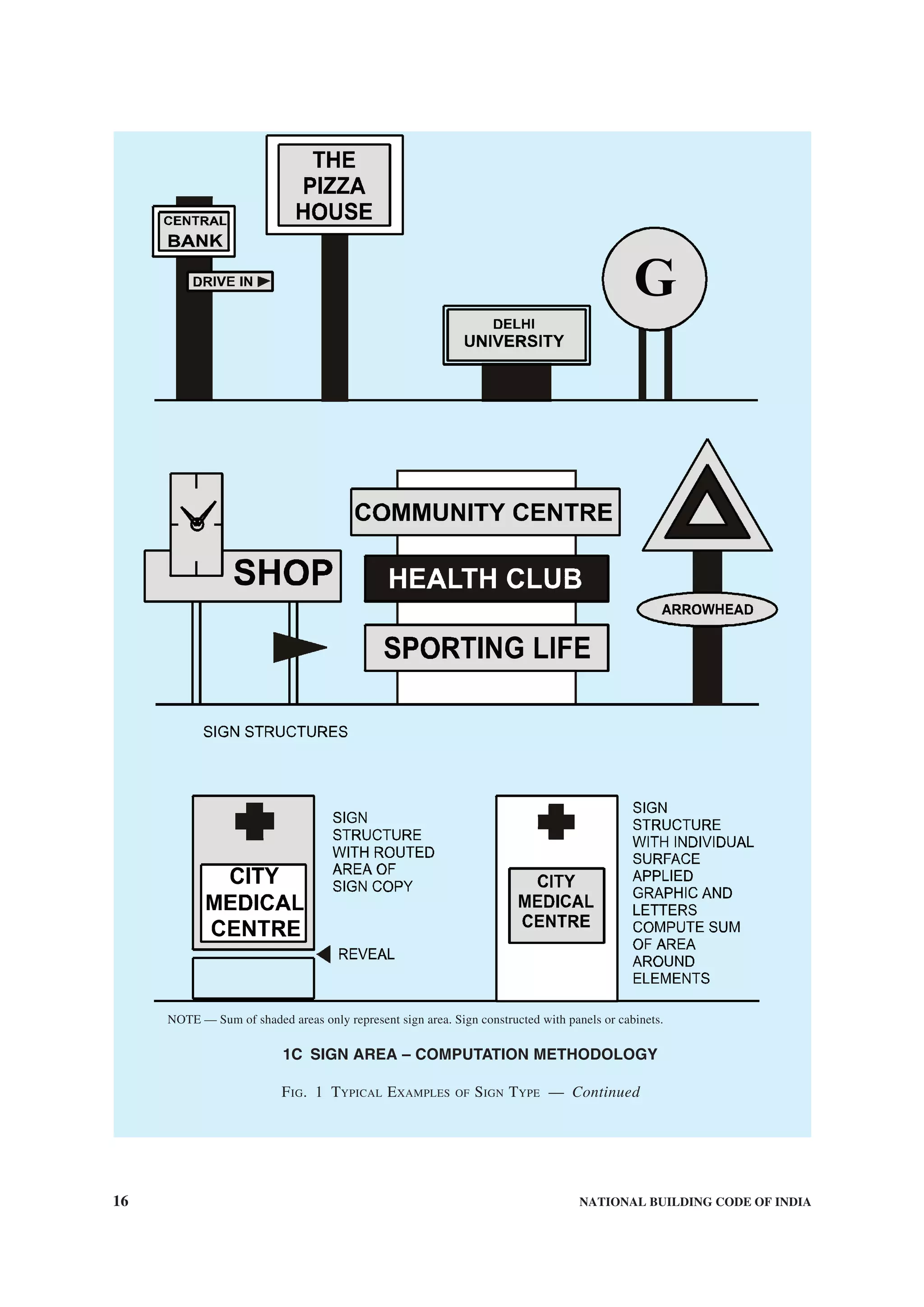
![PART 10 LANDSCAPING, SIGNS AND OUTDOOR DISPLAY STRUCTURES — SECTION 2 SIGNS … 17
NOTE — Sum of shaded areas only represent sign area for compliance purposes. Signs consisting of individual letters,
elements or logos placed on building walls or structures.
1D SIGN AREA – COMPUTATION METHODOLOGY
FIG. 1 TYPICAL EXAMPLES OF SIGN TYPE
6.5 Damage or Defacement by Removal of
Advertising Signs
Whenever any advertising sign is removed, whether
in consequence of a notice or order under the Code
or otherwise, any damage or defacement to the
building or site on or from which such sign was
displayed, shall be made good to the satisfaction of
the Authority.
6.6 Alteration to Ground Level
Whenever any alteration is made to the ground level
adjacent to any advertising sign, the owner of the site
on which sign is erected, shall be responsible for the
alteration of the height of such sign so as to conform
to the requirements of this Section.
6.7 Traffic Control Interference
No advertising sign shall be erected or maintained
which interferes with or is likely to interfere with any
sign or signal for the control of traffic.
6.7.1 No advertising sign shall be placed particularly
in bends and curves so as to obstruct the view of traffic
at intersecting streets.
6.8 Draining of Signs
Adequate provision for drainage shall be made in every
advertising sign, where the possibility of collection of
moisture exists.
6.9 Glass in Signs
All glass used in advertising signs, other than glass
tubing used in gas discharge or similar signs, shall be
of safety glass conforming to accepted standards
[10-2(2)] at least 3 mm thick. Glass panels in
advertising signs shall not exceed 6 m2
in area, each
panel being securely fixed in the body of the sign
independently of all other panels. Glass signs shall be
properly protected from the possibility of damage by
falling objects by the provisions of suitable protecting
metal canopies, or by other approved means. Use of](https://image.slidesharecdn.com/is-200203030013/75/NATIONAL-BUILDING-CODE-SP7-284-2048.jpg)
![18 NATIONAL BUILDING CODE OF INDIA
glass may be discouraged or avoided wherever possible
for signs placed overhead.
6.10 Interference to Fire Hydrants
Advertising signs shall be so placed as not to obstruct
the use of the hydrants or other fire fighting
appliances.
6.11 Serving Devices
Ladders, platforms, hooks, rings and all other devices
for the use of servicing personnel shall have safety
devices and suitable design loadings (reference may
also be made to Part 7 ‘Constructional Practices and
Safety’).
6.12 Animated Devices
Signs which contain moving section or ornaments shall
have fail-safe provisions to prevent the section or
ornaments from releasing and falling or shifting its
centre of gravity more than 450 mm. The fail-safe
device shall be in addition to the mechanism and its
housing which operate the movable section or
ornament. The fail-safe device shall be capable of
supporting the full dead weight of the section or
ornament when moving mechanism releases.
7 ELECTRIC SIGNS AND ILLUMINATED
SIGNS
7.1 Material for Electric Signs
Every electric sign shall be constructed of non-
combustible material except where the sign is purely a
flood-lit sign.
7.2 Installation of Electric Signs and Illuminated
Signs
Every electric sign and illuminated sign shall be
installed in accordance with Part 8 ‘Building Services,
Section 2 Electrical and Allied Installations’.
7.3 No illuminated sign in red, amber or green colour
shall be erected or maintained within a horizontal
distance of 10 m of any illuminated traffic sign.
7.4 All advertising signs illuminated by light other
than a white light at height of less than two storeys or
6 m above the footpath, whichever be the greater
height, shall be suitably screened so as to satisfactorily
prevent any interference with any sign or signal for
the control of traffic.
7.5 Intense Illumination
No person shall erect any sign which is of such intense
illumination as to disturb the residents in adjacent or
nearby residential buildings. Notwithstanding any
permission given for such erection, any such sign
which after erection is, in the opinion of the Authority,
of such intense illumination as to disturb the occupants
of adjacent or nearby buildings shall, on the order of
the Authority, be suitably altered or removed by the
owner of the site concerned within such reasonable
period as the Authority may specify.
7.6 Hours of Operation
No electric sign, other than those necessary in the
opinion of the Authority in the interest of public
amenity, health and safety, shall be operated between
midnight and sunrise.
7.7 Flashing, Occulting and Animated
No flashing, occulting or animated advertising signs,
the periodicity of which exceeds 30 flashes to the
minute, shall be erected so that the lowest point of such
signs is less than 9 m above the ground level.
7.8 For illuminated signs in the vicinity of airports,
the Directorate General of Civil Aviation should be
consulted.
8 GROUND SIGNS
8.1 Material
Every ground sign exceeding 6 m in height together
with frames, supports and braces shall be constructed
of non-combustible material except as in 6.4.
8.2 Dimensions
No ground sign shall be erected to a height exceeding
9 m above the ground. Lighting reflectors may extend
beyond the top or face of the sign.
8.3 Supports and Anchorage
Every ground sign shall be firmly supported and
acnchored to the ground. Supports and anchors shall
be of treated timber in accordance with good practice
[10-2(3)], or metal treated for corrosion resistance or
masonry or concrete.
8.4 Site Cleaning
The owner of any site on which a ground sign is erected
shall be responsible for keeping such part of the site as
is visible from the street, clean, sanitary, unoffensive
and free of all obnoxious substances and unsightly
conditions to the approval of the Authority.
8.5 Obstruction to Traffic
No ground sign shall be erected so as to obstruct free
access to or egress from any building.
8.6 Set Back
No ground sign shall be set nearer to the street line
than the established building line.](https://image.slidesharecdn.com/is-200203030013/75/NATIONAL-BUILDING-CODE-SP7-285-2048.jpg)
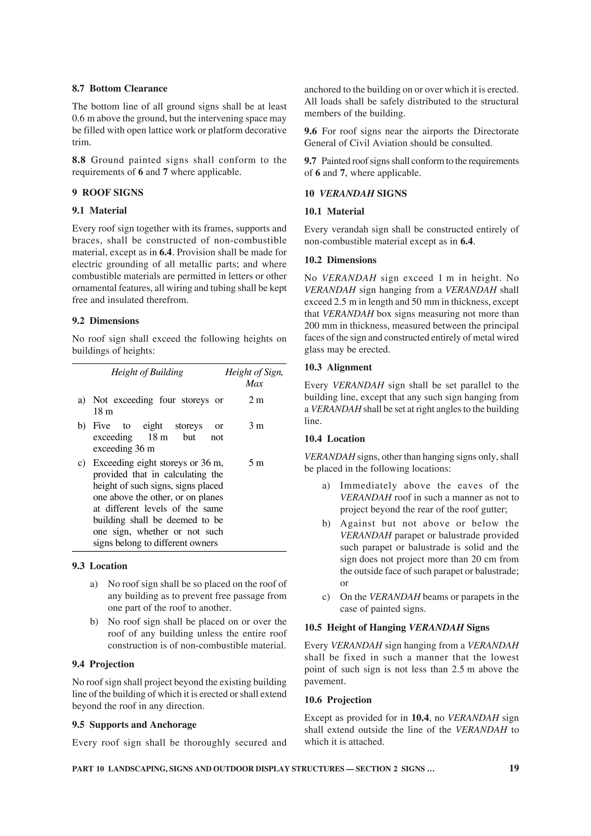
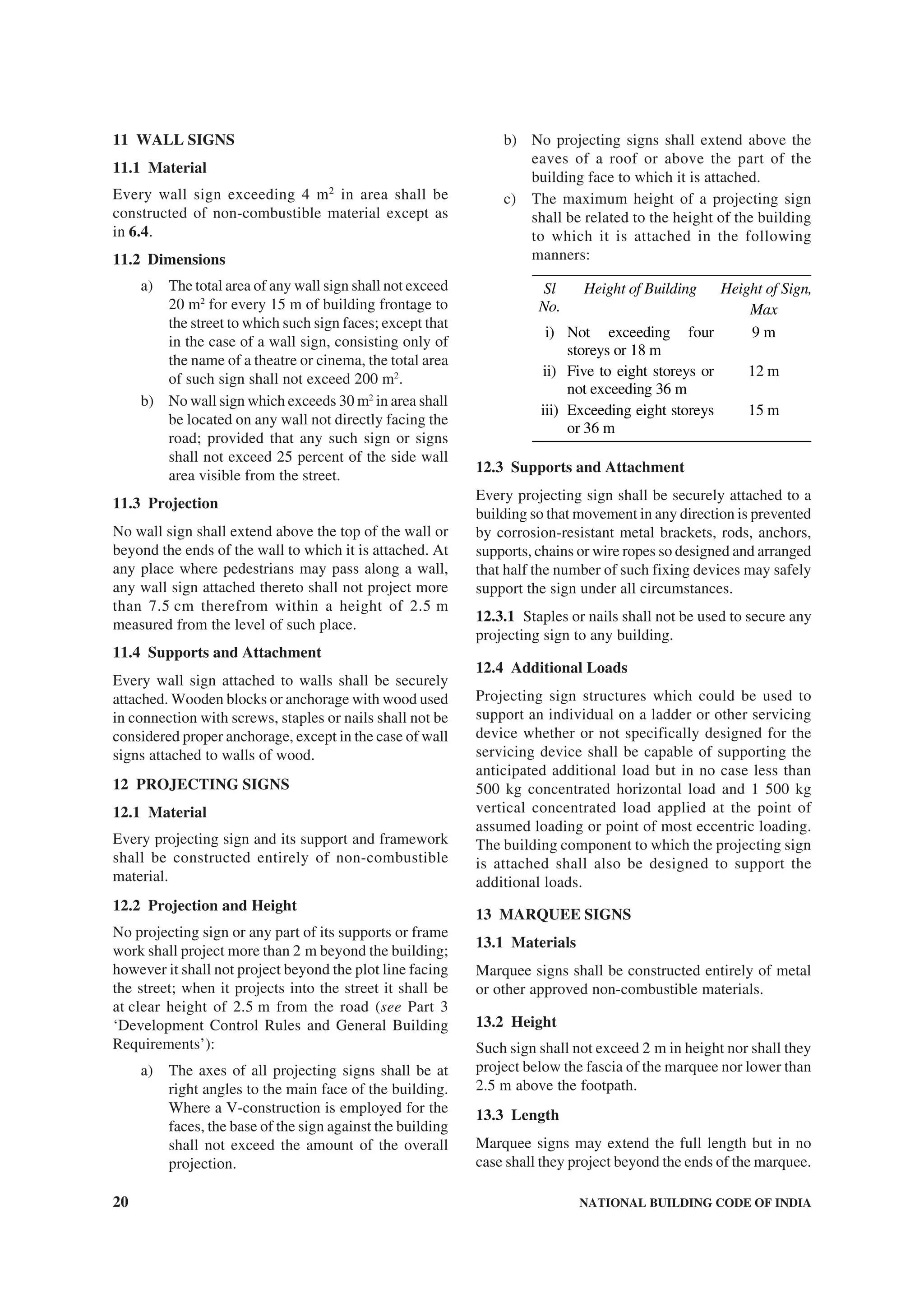
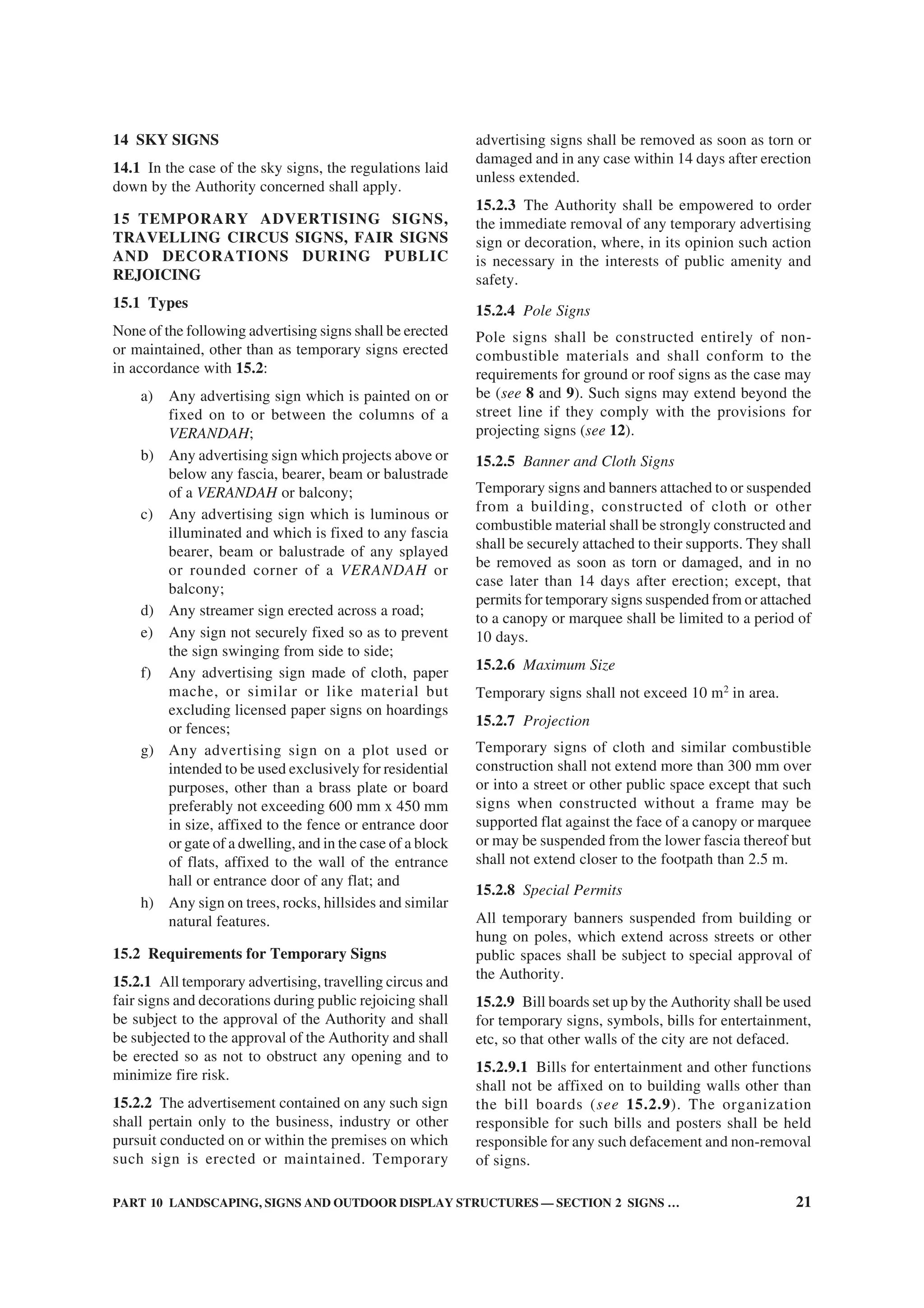
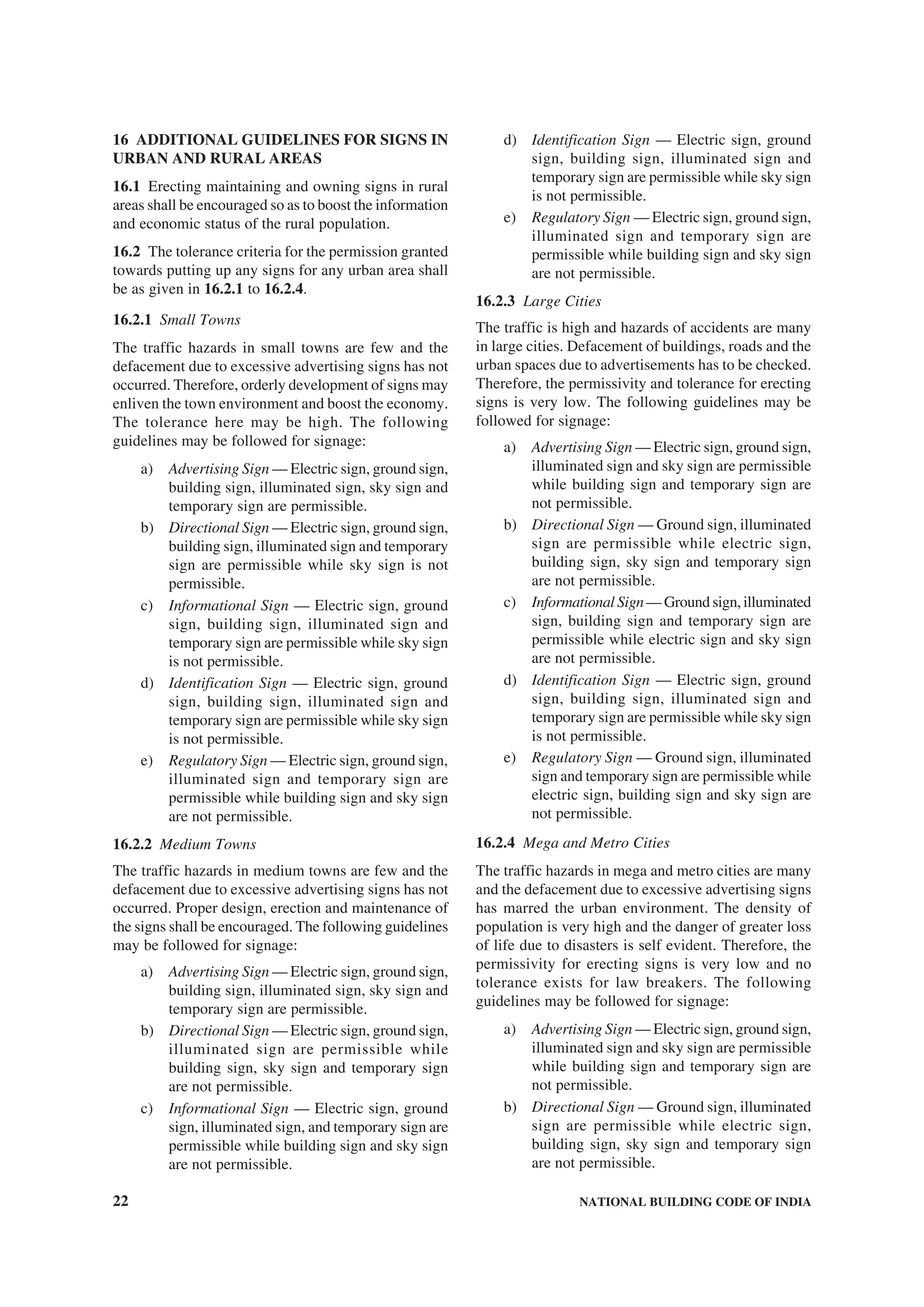
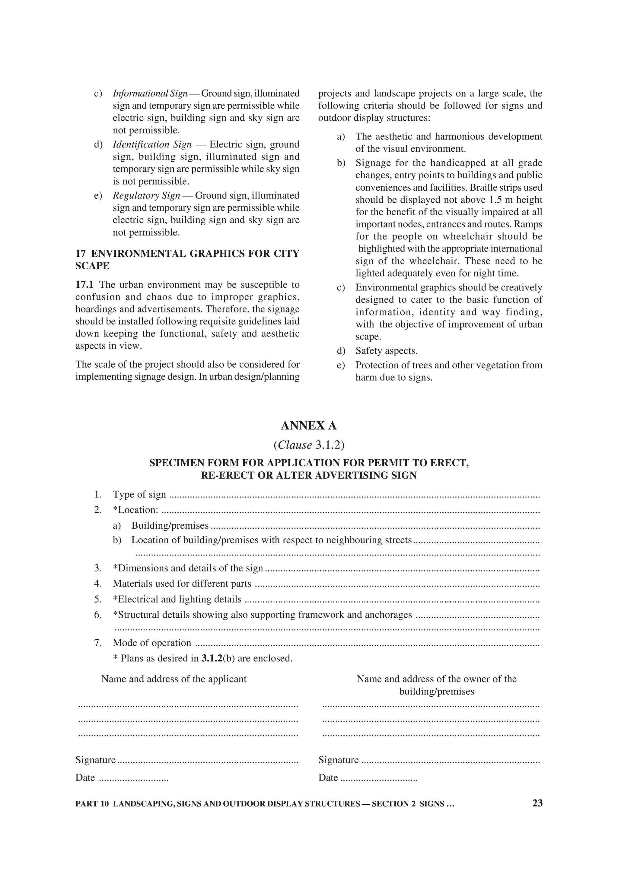
![Disclosure to Promote the Right To Information
Whereas the Parliament of India has set out to provide a practical regime of right to
information for citizens to secure access to information under the control of public authorities,
in order to promote transparency and accountability in the working of every public authority,
and whereas the attached publication of the Bureau of Indian Standards is of particular interest
to the public, particularly disadvantaged communities and those engaged in the pursuit of
education and knowledge, the attached public safety standard is made available to promote the
timely dissemination of this information in an accurate manner to the public.
इंटरनेट मानक
“!ान $ एक न' भारत का +नम-ण”
Satyanarayan Gangaram Pitroda
“Invent a New India Using Knowledge”
“प0रा1 को छोड न' 5 तरफ”
Jawaharlal Nehru
“Step Out From the Old to the New”
“जान1 का अ+धकार, जी1 का अ+धकार”
Mazdoor Kisan Shakti Sangathan
“The Right to Information, The Right to Live”
“!ान एक ऐसा खजाना > जो कभी च0राया नहB जा सकता है”
Bhartṛhari—Nītiśatakam
“Knowledge is such a treasure which cannot be stolen”
“Invent a New India Using Knowledge”
है”ह”ह
SP 7 : Group 1 (2005): NATIONAL BUILDING CODE OF INDIA 2005
GROUP 1 [CED 46: National Building Code]](https://crownmelresort.com/image.slidesharecdn.com/is-200203030013/75/NATIONAL-BUILDING-CODE-SP7-1-2048.jpg)


![( ix )
Organization Representative(s)
Indian Institute of Technology (Centre for Energy Studies), PROF N. K. BANSAL
New Delhi
Indian Roads Congress, New Delhi CHIEF ENGINEER (DESIGN), CPWD
SUPERINTENDING ENGINEER (DESIGN), CPWD (Alternate)
Institute of Town Planners, India, New Delhi DR S. K. KULSHRESTHA
Institution of Fire Engineers (India), New Delhi PRESIDENT
GENERAL SECRETARY (Alternate)
Ministry of Home Affairs, New Delhi FIRE ADVISOR
Ministry of Home Affairs (Disaster Management Division), SHRI M. P. SAJNANI
New Delhi SHRI S. K. SWAMI (Alternate)
Ministry of Non-Conventional Energy Sources, New Delhi DR T. C. TRIPATHI
Ministry of Road Transport and Highways, New Delhi SHRI S. B. BASU
SHRI P. HALDER (Alternate)
Municipal Corporation of Greater Mumbai, Mumbai DIRECTOR (ENGG SERVICES & PROJECTS)
CITY ENGINEER (Alternate)
National Buildings Construction Corporation, New Delhi SHRI B. PRASAD
SHRI N. P. AGARWAL (Alternate)
National Council for Cement and Building Materials, Ballabgarh SHRI SHIBAN RAINA
DR ANIL KUMAR (Alternate)
National Design and Research Forum, The Institution of Engineers PROF R. NARAYANA IYENGAR
(India), Bangalore SHRI B. SURESH (Alternate)
National Environmental Engineering Research Institute (CSIR), DR ARINDAM GHOSH
Nagpur DR V. P. DESHPANDE (Alternate)
North Eastern Council, Shillong SHRI P. K. DEB
Public Works Department (Roads and Buildings), Gandhinagar SHRI V. P. JAMDAR
SHRI M. S. JALLUNDHWALA (Alternate)
Research, Designs and Standards Organization (Ministry of Railways), SHRI R. K. GUPTA
Lucknow SHRI J. P. DAS (Alternate)
School of Planning and Architecture, New Delhi DIRECTOR
Structural Engineering Research Centre (CSIR), Chennai SHRI C. V. VAIDYANATHAN
SHRI K. MANI (Alternate)
Suri and Suri Consulting Acoustical Engineers, New Delhi SHRI GAUTAM SURI
The Energy and Resources Institute, New Delhi MS MILI MAJUMDAR
MS VIDISHA SALUNKE-PALSULE (Alternate)
The Indian Institute of Architects, New Delhi SHRI BALBIR VERMA
SHRI ABHIJIT RAY (Alternate)
The Institution of Engineers (India), Kolkata PROF G. P. LAL
SHRI O. P. GOEL (Alternate)
The Institution of Surveyors, New Delhi SHRI K. S. KHARB
SHRI R. K. BHALLA (Alternate)
Town and Country Planning Organization, New Delhi SHRI K. T. GURUMUKHI
SHRI J. B. KSHIRSAGAR (Alternate)
U.P. Housing and Development Board, Lucknow SHRI HARI GOPAL
Unitech Ltd, Gurgaon SHRI SUSHIL SHARMA
SHRI SHAHID MAHMOOD (Alternate)
In personal capacity (5, Sunder Nagar, New Delhi 110 003) DR J. R. BHALLA
BIS Directorate General SHRI S. K. JAIN, Director & Head (Civil Engineering)
[Representing Director General (Ex-officio Member)]
Member Secretary
SHRI SANJAY PANT
Joint Director (Civil Engineering), BIS](https://crownmelresort.com/image.slidesharecdn.com/is-200203030013/75/NATIONAL-BUILDING-CODE-SP7-11-2048.jpg)


![( xiii )
Important Explanatory Note for Users of Code
In this Code, where reference is made to ‘accepted standards’ in relation to material
specification, testing or other related information or where reference is made to ‘good practice’
in relation to design, constructional procedures or other related information, the Indian
Standards listed at the end of the concerned Parts/Sections may be used to the interpretation
of these terms.
At the time of publication, the editions indicated in the above Indian Standards were valid.
All standards are subject to revision and parties to agreements based on the Parts/Sections
are encouraged to investigate the possibility of applying the most recent editions of the
standards.
In the list of standards given at the end of each Part/Section, the number appearing in the
first column indicates the number of the reference in that Part/Section. For example:
a) accepted standard [3(1)] refers to the standard given at serial number 1 of the list of
standards given at the end of Part 3, that is IS 8888 (Part 1) : 1993 ‘Guide for
requirements of low income housing: Part 1 Urban area (first revision)’.
b) good practice [4(3)] refers to the standard given at serial number 3 of the list of standards
given at the end of Part 4, that is IS 15394 : 2003 ‘Code of practice for fire safety in
petroleum refinery and fertilizer plants’.
c) accepted standard [4(11)] refers to the standard given at serial number 11 of the list of
standards given at the end of Part 4, that is IS 11360 : 1985 ‘Specification for smoke
detectors for use in automatic electrical fire alarm system’.
d) good practice [4(28)] refers to the standard given at serial number 28 of the list of
standards given at the end of Part 4, that is IS 12456 : 1988 ‘Code of practice for fire
protection of electronic data processing installations’.
e) good practice [10-2(3)] refers to the standard given at serial number 3 of the list of
standards given at the end of Section 2 of Part 10, that is IS 401 : 2001 ‘Code of
practice for preservation of timber (fourth revision)’.](https://crownmelresort.com/image.slidesharecdn.com/is-200203030013/75/NATIONAL-BUILDING-CODE-SP7-15-2048.jpg)


![PART 2 ADMINISTRATION 15
objections are raised when they are resubmitted after
compliance of earlier objections.
12.10.4 Once the plan has been scrutinized and
objections have been pointed out, the owner giving
notice shall modify the plan to comply with the
objections raised and re-submit it. The Authority shall
scrutinize the re-submitted plan and if there be further
objections, the plan shall be rejected.
13 RESPONSIBILITIES AND DUTIES OF THE
OWNER
13.1 Neither the granting of the permit nor the approval
of the drawings and specifications, nor inspections
made by the Authority during erection of the building
shall in any way relieve the owner of such building
from full responsibility for carrying out the work in
accordance with the requirements of the Code (see 9).
13.2 Every owner shall:
a) permit the Authority to enter the building or
premises for which the permit has been
granted at any reasonable time for the purpose
of enforcing the Code;
b) submit a document of ownership of the site;
c) obtain, where applicable, from the Authority,
permits relating to building, zoning, grades,
sewers, water mains, plumbing, signs,
blasting, street occupancy, electricity,
highways, and all other permits required in
connection with the proposed work;
d) give notice to the Authority of the intention
to start work on the building site (see
Annex F);
e) give written notice to the Authority intimating
completion of work up to plinth level;
f) submit the certificate for execution of work
as per structural safety requirements (see
Annex G); and give written notice to the
Authority regarding completion of work
described in the permit (see Annex H);
g) give written notice to the Authority in case of
termination of services of a professional
engaged by him; and
h) obtain an occupancy permit (see Annex J)
from the Authority prior to any:
1) occupancy of the building or part thereof
after construction or alteration of that
building or part, or
2) change in the class of occupancy of any
building or part thereof.
13.2.1 Temporary Occupancy
Upon the request of the holder of the permit, the
Authority may issue a temporary certificate of
occupancy for a building or part thereof, before the
entire work covered by permit shall have been
completed, provided such portion or portions may be
occupied safely prior to full completion of building
without endangering life or public welfare.
13.3 Documents at Site
13.3.1 Where tests of any materials are made to ensure
conformity with the requirements of the Code, records
of the test data shall be kept available for inspection
during the construction of the building and for such a
period thereafter as required by the Authority.
13.3.2 The person to whom a permit is issued shall
during construction keep pasted in a conspicuous place
on the property in respect of which the permit was
issued:
a) a copy of the building permit; and
b) a copy of the approved drawings and
specifications referred in 12.
14 INSPECTION, OCCUPANCY PERMIT AND
POST-OCCUPANCY INSPECTION
14.1 Generally all construction or work for which a
permit is required shall be subject to inspection by the
Authority and certain types of construction involving
unusual hazards or requiring constant inspection shall
have continuous inspection by special inspectors
appointed by the Authority.
14.2 Inspection, where required, shall be made within
7 days following the receipt of notification, after
which period the owner will be free to continue the
construction according to the sanctioned plan. At the
first inspection, the Authority shall determine to the
best of its ability that the building has been located
in accordance with the approved site plans. The final
inspection of the completion of the work shall be
made within 21 days following the receipt of
notification [see 13.2(f)] for the grant of occupancy
certificate.
14.2.1 The owner/concerned registered architect/
engineer/structural engineer/town planner will serve
a notice/completion certificate to the Authority that
the building has been completed in all respects as per
the approved plans. The deviations shall also be
brought to the notice of the Authority (with relevant
documents). The team of building officials or its duly
authorized representative shall then visit the site and
occupancy certificate shall be given in one instance.
14.2.2 The occupancy certificate should clearly state
the use/type of occupancy of the building. However,
the applicant can apply for change of use/occupancy
permitted within the purview of the Master Plan/Zonal
Plan/Building Byelaws, where so required.](https://crownmelresort.com/image.slidesharecdn.com/is-200203030013/75/NATIONAL-BUILDING-CODE-SP7-42-2048.jpg)


![22 NATIONAL BUILDING CODE OF INDIA
ANNEX E
(Clause 12.10)
FORM FOR SANCTION OR REFUSAL OF DEVELOPMENT/BUILDING PERMIT
To
...............................................
...............................................
...............................................
Sir,
With reference to your application ........................................dated ........................................for grant of permit
for the development, erection, re-erection or material alteration in the building No. ........................................
or to....................................................on/in Plot No....................................................................in Colony/
Street............................................MOHALLA/BAZAR/Road...........................................City...............................
I have to inform you that the sanction has been granted/refused by the Authority on the following grounds:
1.
2.
3.
4.
5.
6.
Office Stamp ............................................... Signature of the Authority ........................................
Office (Communication) No. ...................... Name, Designation and Address
of the Authority.......................................................
Date: ............................ .......................................................
.......................................................
ANNEX F
[Clause 13.2 (d)]
FORM FOR NOTICE FOR COMMENCEMENT
I hereby certify that the development, erection, re-erection or material alteration in/of building No. ...........................
or the..............................on/in Plot No....................................in Colony/Street.....................................MOHALLA/
BAZAR/Road....................................City ....................................will be commenced on as per your permission,
vide No.....................................dated..............................under the supervision of ....................................Registered
Architect/Engineer/Structural Engineer/Supervisor/Town Planner/Landscape Architect/Urban Designer1)
,
Registration No...............................................................and in accordance with the plans sanctioned, vide
No.....................................dated............................
Signature of Owner ....................................................
Name of Owner ..........................................................
(in block letters)
Address of Owner.......................................................
.......................................................
Date: ............................ .......................................................
1)
Strike out whichever is not applicable.](https://crownmelresort.com/image.slidesharecdn.com/is-200203030013/75/NATIONAL-BUILDING-CODE-SP7-49-2048.jpg)
![PART 2 ADMINISTRATION 23
ANNEX G
[Clause 13.2(f)]
FORM FOR CERTIFICATE FOR EXECUTION OF WORK AS PER
STRUCTURAL SAFETY REQUIREMENTS
With respect to the building work of erection, re-erection or for making alteration in the building No..........................
or to ................................on/in Plot No.......................................Colony/Street ...................................MOHALLA/
BAZAR/Road ................................City................................, we certify:
a) that the building has been constructed according to the sanctioned plan and structural design (one set of
drawings as executed enclosed), which incorporates the provisions of structural safety as specified in
Part 6 ‘Structural Design’ of the National Building Code of India and other relevant Codes; and
b) that the construction has been done under our supervision and guidance and adheres to the drawings and
specifications submitted and records of supervision have been maintained.
Any subsequent changes from the completion drawings shall be the responsibility of the owner.
Signature of owner Signature of the
with date Registered Engineer/
Structural Engineer with
date and registration No.
Name: ........................................... ..........................................
Address: ........................................... ..........................................
ANNEX H
[Clause 13.2 (f)]
FORM FOR COMPLETION CERTIFICATE
I hereby certify that the development, erection, re-erection or material alteration in/of building No...........................
or the ........................... on/in Plot No............................ in Colony/Street ........................... MOHALLA/BAZAR/
Road...........................City........................... has been supervised by me and has been completed on ...........................
........................... according to the plans sanctioned, vide No. ........................... dated ...................... The work
has been completed to my best satisfaction, the workmanship and all the materials (type and grade) have been
used strictly in accordance with general and detailed specifications. No provisions of the Code, no requisitions
made, conditions prescribed or orders issued thereunder have been transgressed in the course of the work. The
land is fit for construction for which it has been developed or re-developed or the building is fit for use for which
it has been erected, re-erected or altered, constructed and enlarged.
I hereby also enclose the plan of the building completed in all aspects.
Signature of Architect/Engineer/Structural Engineer/Supervisor/Town Planner/Landscape Architect/Urban
Designer1)
.....................................................................
Name of Architect/Engineer/Structural Engineer/Supervisor/Town Planner/Landscape Architect/Urban
Designer1)
.....................................................................
(in block letters)
Registration No. of Architect/Engineer/Structural Engineer/Supervisor/Town Planner/Landscape Architect/Urban
Designer1)
.....................................................................
Address of Architect/Engineer/Structural Engineer/Supervisor/Town Planner/Landscape Architect/Urban
Designer1)
.....................................................................
Date: ............................. Signature of the Owner
1)
Strike out whichever is not applicable.](https://crownmelresort.com/image.slidesharecdn.com/is-200203030013/75/NATIONAL-BUILDING-CODE-SP7-50-2048.jpg)
![24 NATIONAL BUILDING CODE OF INDIA
ANNEX J
[Clause 13.2(h)]
FORM FOR OCCUPANCY PERMIT
The work of erection, re-erection or alteration in/of building No.............................or the...............................on/
in Plot No.............................in Colony/Street.......................................MOHALLA/BAZAR/Road.................................
City.............................completed under the supervision of........................................Architect/Engineer/Structural
Engineer/Supervisor, Registration No.............................has been inspected by me. The building can be permitted/
not permitted for occupation for .............................occupancy subjected to the following:
1.
2.
3.
One set of completion plans duly certified is returned herewith.
Signature of the Authority ...................................
Office Stamp
Date: .........................](https://crownmelresort.com/image.slidesharecdn.com/is-200203030013/75/NATIONAL-BUILDING-CODE-SP7-51-2048.jpg)


![PART 3 DEVELOPMENT CONTROL RULES AND GENERAL BUILDING REQUIREMENTS 25
c) Outer courtyard — The minimum width of
the outer courtyard (as distinguished from its
depth) shall be not less than 2.4 m. If the width
of the outer courtyard is less than 2.4 m, it
shall be treated as a notch and the provisions
of outer courtyard shall not apply. However,
if the depth of the outer courtyard is more than
the width, the provisions of 8.1.2 shall apply
for the open spaces to be left between the
wings.
8.2.6 Joint Open Air Space
Every such interior or exterior open air space, unless
the latter is a street, shall be maintained for the benefit
of such building exclusively and shall be entirely within
the owner’s own premises.
8.2.6.1 If such interior or exterior open air space is
intended to be used for the benefit of more than one
building belonging to the same owner, the width of
such open air space shall be the one specified for the
tallest building as specified in 8.2.3 abutting on such
open air space.
8.2.6.2 If such interior or exterior open air space is
jointly owned by more than one person, its width shall
also be as specified in 8.2, provided every such person
agrees in writing to allow his portion of such joint open
air space to be used for the benefit of every building
abutting on such joint open air space and provided he
sends such written consent to the Authority for record.
Such common open air space shall thenceforth be
treated as a permanently open air space required for
the purposes of the Code. No boundary wall between
such joint open air space shall be erected or raised to a
height of more than 2.0 m.
8.3 Other Occupancies
8.3.1 Open spaces for other occupancies shall be as
below:
a) Educational buildings — Except for nursery
schools, the open spaces around the building
shall be not less than 6 m.
b) Institutional buildings — The open spaces
around the building shall be not less than 6 m.
c) Assembly buildings — The open space at front
shall be not less than 12 m and the other open
spaces around the building shall be not less
than 6 m.
NOTE — However, if assembly buildings are permitted
in purely residential zones, the open spaces around the
building shall be not less than 12 m.
d) Business, mercantile and storage buildings —
The open spaces around the building shall be
not less than 4.5 m. Where these occur in a
purely residential zone or in a residential with
shops line zone the open spaces may be
relaxed.
e) Industrial buildings — The open spaces
around the building shall be not less than
4.5 m for heights up to 16 m, with an increase
of the open spaces of 0.25 m for every
increase of 1 m or fraction thereof in height
above 16 m.
NOTE — Special rules for narrow industrial plots in
the city, namely plots less than 15 m in width, and with
appropriate set-backs from certain streets and highways,
shall be applicable.
f) Hazardous occupancies — The open spaces
around the building shall be as specified for
industrial buildings [see 8.3.1 (e)].
8.4 Exemption to Open Spaces
8.4.1 Projections into Open Spaces
Every open space provided either interior or exterior
shall be kept free from any erection thereon and shall
be open to the sky, except as below:
a) Cornice, roof or weather shade not more than
0.75 m wide;
b) Sunshades over windows/ventilators or other
openings not more than 0.75 m wide;
c) Canopy not to be used as a sit out with
clearance of 1.5 m between the plot boundary
and the canopy;
d) Projected balcony at higher floors of width
not more than 1.2 m; and
e) Projecting rooms/balconies [see (d)] at
alternate floors such that rooms of the lower
two floors get light and air and the projection
being not more than the height of the storey
immediately below.
However, these projections into open spaces shall not
reduce the minimum required open spaces.
8.4.1.1 Accessory building
The following accessory buildings may be permitted
in the open spaces:
a) In an existing building, sanitary block of
2.4 m in height subject to a maximum of 4 m2
in the rear open space at a distance of 1.5 m
from the rear boundary may be permitted,
where facilities are not adequate.
b) Parking lock up garages not exceeding 2.4 m
in height shall be permitted in the side or
rear open spaces at a distance of 7.5 m from
any road line or the front boundary of the plot;
and
c) Suction tank and pump room each up to
2.5 m2
in area.](https://crownmelresort.com/image.slidesharecdn.com/is-200203030013/75/NATIONAL-BUILDING-CODE-SP7-75-2048.jpg)


![PART 3 DEVELOPMENT CONTROL RULES AND GENERAL BUILDING REQUIREMENTS 33
12.15 Septic Tanks
Where a septic tank is used for sewage disposal, the
location, design and construction of the septic tank shall
conform to requirements of 12.15.1 and 12.15.2 [see
also Part 9 ‘Plumbing Services, Section 1 Water
Supply, Drainage and Sanitation (Including Solid
Waste Management)’].
12.15.1 Location of the Septic Tanks and Subsurface
Absorption Systems
A sub-soil dispersion system shall not be closer than
18 m from any source of drinking water, such as well,
to mitigate the possibility of bacterial pollution of water
supply. It shall also be as far removed from the nearest
habitable building as economically feasible but not
closer than 6 m, to avoid damage to the structures.
12.15.2 Requirements
a) Dimensions of septic tanks — Septic tanks
shall have a minimum width of 750 mm, a
minimum depth of 1 m below the water level
and a minimum liquid capacity of 1 m3
. The
length of tanks shall be 2 to 4 times the width;
b) Septic tanks may be constructed of brickwork,
stone masonry, concrete or other suitable
materials as approved by the Authority;
c) Under no circumstances shall effluent from a
septic tank be allowed into an open channel
drain or body of water without adequate
treatment;
d) The minimum nominal diameter of the pipe
shall be 100 mm. Further, at junctions of pipes
in manholes, direction of flow from a branch
connection shall not make an angle exceeding
45° with the direction of flow in the main pipe;
e) The gradients of land drains, under-drainage
as well as the bottom of dispersion trenches
and soakways shall be between 1:300 and
1:400;
f) Every septic tank shall be provided with
ventilating pipe of at least 50 mm diameter.
The top of the pipe shall be provided with a
suitable cage of mosquito-proof wire mesh.
The ventilating pipe shall extend to a height
which would cause no smell nuisance to any
building in the area. Generally, the ventilating
pipe may extend to a height of about 2 m,
when the septic tank is at least 15 m away
from the nearest building and to a height of
2 m above the top of the building when it is
located closer than 15 m;
g) When the disposal of septic tank effluent is
to a seepage pit, the seepage pit may be of
any suitable shape with the least cross-
sectional dimension of 0.90 m and not less
than 1.00 m in depth below the invert level of
the inlet pipe. The pit may be lined with stone,
brick or concrete blocks with dry open joints
which should be backed with at least 75 mm
of clean coarse aggregate. The lining above
the inlet level should be finished with mortar.
In the case of pits of large dimensions, the
top portion may be narrowed to reduce the
size of the RCC cover slabs. Where no lining
is used, specially near trees, the entire pit
should be filled with loose stones. A masonry
ring may be constructed at the top of the pit
to prevent damage by flooding of the pit by
surface runoff. The inlet pipe may be taken
down a depth of 0.90 m from the top as an
anti-mosquito measure; and
h) When the disposal of the septic tank effluent
is to a dispersion trench, the dispersion trench
shall be 0.50 m to 1.00 m deep and 0.30 m to
1.00 m wide excavated to a slight gradient
and shall be provided with 150 mm to 250 mm
of washed gravel or crushed stones. Open
jointed pipes placed inside the trench shall
be made of unglazed earthenware clay or
concrete and shall have a minimum internal
diameter of 75 mm to 100 mm. Each
dispersion trench shall not be longer than
30 m and trenches shall not be placed closer
than 1.8 m.
12.16 Office-cum-Letter Box Room
In the case of multi-storeyed multi-family dwelling
apartments constructed by existing and proposed
Cooperative Housing Societies or Apartment Owners
Associations, limited companies and proposed
societies, an office-cum-letter box room of dimension
3.6 m × 3 m shall be provided on the ground floor. In
case the number of flats is more than 20, the maximum
size of the office-cum-letter box room shall be 20 m2
.
12.16.1 Business Buildings
Provision shall be made for letter boxes on the entrance
floor as per the requirements of the postal department.
12.17 Meter Rooms
For all buildings above 15 m in height and in special
occupancies, like educational, assembly, institutional,
industrial, storage, hazardous and mixed occupancies
with any of the aforesaid occupancies having area more
than 500 m2
on each floor, provision shall be made for
an independent and ventilated meter (service) room,
as per requirements of electric (service) supply
undertakings on the ground floor with direct access
from outside for the purpose of termination of electric](https://crownmelresort.com/image.slidesharecdn.com/is-200203030013/75/NATIONAL-BUILDING-CODE-SP7-83-2048.jpg)
![34 NATIONAL BUILDING CODE OF INDIA
supply from the licensee’s service and alternative
supply cables. The door/doors provided for the service
room shall have fire resistance of not less than two
hours.
12.18 Staircase/Exit Requirements
12.18.1 The minimum clear width, minimum tread
width and maximum riser of staircases for buildings
shall be as given in 12.18.1.1 to 12.18.1.3 (see also
Part 4 ‘Fire and Life Safety’).
12.18.1.1 Minimum width — The minimum width of
staircase shall be as follows:
a) Residential buildings (dwellings) 1.0 m
NOTE — For row housing with 2 storeys,
the minimum width shall be 0.75 m.
b) Residential hotel buildings 1.5 m
c) Assembly buildings like 2.0 m
auditoria, theatres and cinemas
d) Educational building 1.5 m
e) Institutional buildings 2.0 m
f) All other buildings 1.5 m
12.18.1.2 Minimum tread
The minimum width of tread without nosing shall be
250 mm for residential buildings. The minimum width
of tread for other buildings shall be 300 mm.
12.18.1.3 Maximum riser
The maximum height of riser shall be 190 mm for
residential buildings and 150 mm for other buildings
and these shall be limited to 12 per flight.
12.18.2 The minimum head-room in a passage under
the landing of a staircase shall be 2.2 m. The minimum
clear head-room in any staircase shall be 2.2 m.
12.18.3 Exit Requirements
All aspects of exit requirements for corridors, doors,
stair cases, ramps, etc in respect of widths, travel
distance shall be as per Part 4 ‘Fire and Life Safety’.
12.19 Roofs
12.19.1 The roof of a building shall be so designed
and constructed as to effectively drain water by means
of sufficient rain-water pipes of adequate size,
wherever required, so arranged, jointed and fixed as
to ensure that the rain-water is carried away from the
building without causing dampness in any part of the
walls, roof or foundations of the building or an adjacent
building.
12.19.2 The Authority may require rain-water pipes
to be connected to a drain or sewer to a covered channel
formed beneath the public footpath to connect the rain-
water pipe to the road gutter or in any other approved
manner.
12.19.3 Rain-water pipes shall be affixed to the
outside of the external walls of the building or in
recesses or chases cut or formed in such external walls
or in such other manner as may be approved by the
Authority.
12.19.4 It is desirable to conserve rain water using
suitable rain water harvesting techniques including by
roof water collection. In this context, reference may
be made to Part 9 ‘Plumbing Services, Section 1 Water
Supply, Drainage and Sanitation (Including Solid
Waste Management)’.
12.20 Special Requirements of Low Income
Housing
Special requirements of low income housing shall be
as given in Annex C. For detailed information in this
regard, reference may be made to the accepted
standards [3(1)].
12.21 SpecialRequirementsforPhysicallyChallenged
Special requirements for planning of buildings and
facilities keeping in view the needs of the physically
challenged, applicable particularly to public buildings
meant for their use, are given in Annex D.
12.22 Special Requirements for Cluster Planning
for Housing
Special requirements for cluster planning for housing
shall be as given in Annex E.
12.23 Special Requirements for Low Income
Habitat Planning in Rural Areas
Special requirements for low income habitat planning
in rural areas shall be as given in Annex F.
12.24 Special Requirements for Development
Planning in Hilly Areas
Special requirements for development planning in hilly
areas is given in Annex G.
13 FIRE AND LIFE SAFETY
For requirements regarding fire and life safety for
different occupancies, reference shall be made to Part 4
‘Fire and Life Safety’.
14 DESIGN AND CONSTRUCTION
For requirements regarding structural design, reference
shall be made to Part 6 ‘Structural Design’ and for
construction (including safety) reference shall be made
to Part 7 ‘Constructional Practices and Safety’.
15 LIGHTING AND VENTILATION
15.1 For requirements regarding lighting and](https://crownmelresort.com/image.slidesharecdn.com/is-200203030013/75/NATIONAL-BUILDING-CODE-SP7-84-2048.jpg)
![PART 3 DEVELOPMENT CONTROL RULES AND GENERAL BUILDING REQUIREMENTS 35
ventilation for different uses and occupancies,
reference shall be made to Part 8 ‘Building Services,
Section 1 Lighting and Ventilation’.
15.1.1 Lighting and Ventilation of Rooms
Rooms shall have, for the admission of light and air,
one or more openings, such as windows and ventilators,
opening directly to the external air or into an open
VERANDAH.
15.1.2 Notwithstanding the area of openings obtained
through 15.1, the minimum aggregate area (see Notes
1 to 3) of such openings, excluding doors inclusive of
frames, shall be not less than:
a) one-tenth of the floor area for dry hot climate;
b) one-sixth of the floor area for wet hot
climate;
c) one-eighth of the floor area for intermediate
climate; and
d) one-twelfth of the floor area for cold climate.
NOTES
1 If a window is partly fixed, the openable area shall
be counted.
2 No portion of a room shall be assumed to be lighted,
if it is more than 7.5 m away from the opening assumed
for lighting that portion.
3 The area of openings as given in (a) to (d) above
shall be increased by 25 percent in the case of a kitchen
[see 12.3.3(d)].
16 ELECTRICALANDALLIEDINSTALLATIONS
(INCLUDING LIGHTNING PROTECTION OF
BUILDINGS)
For requirements regarding electrical installations in
buildings including lightning protection of buildings,
reference shall be made to Part 8 ‘Building Services,
Section 2 Electrical and Allied Installations’.
17 AIR CONDITIONING, HEATING AND
MECHANICAL VENTILATION
For requirements regarding design, construction and
installation of air conditioning, heating and mechanical
ventilation systems, reference shall be made to Part 8
‘Building Services, Section 3 Air Conditioning,
Heating and Mechanical Ventilation’.
18 ACOUSTICS, SOUND INSULATION AND
NOISE CONTROL
For requirements regarding the desired noise levels and
sound insulation in different occupancies, reference
shall be made to Part 8 ‘Building Services, Section 4
Acoustics, Sound Insulation and Noise Control’.
19 HEAT INSULATION
For calculation of solar radiation on buildings and
recommended limits of thermal transmittance of roofs
and walls for different parts of the country and heat
transmission losses due to different constructions,
reference may be made to good practice [3(2)].
20 INSTALLATION OF LIFTS AND
ESCALATORS
Provision for lifts shall be made for buildings 15 m or
more in height. For requirements regarding planning,
designing and installation, etc of lifts and escalators,
reference shall be made to Part 8 ‘Building Services,
Section 5 Installation of Lifts and Escalators’.
21 PLUMBING SERVICES AND SOLID WASTE
MANAGEMENT
For requirements regarding water supply, drainage and
sanitation (including solid waste management) and gas
supply, reference shall be made to Part 9 ‘Plumbing
Services’.](https://crownmelresort.com/image.slidesharecdn.com/is-200203030013/75/NATIONAL-BUILDING-CODE-SP7-85-2048.jpg)


![44 NATIONAL BUILDING CODE OF INDIA
clear height below and above the mezzanine floor
should be 2.4 m and 2.1 m respectively.
As far as possible mezzanine floor should have direct
ventilation from the external face of the building.
Where this is not possible ventilation through main
room may be allowed provided total area of openings
in the main room is provided taking into consideration
area of mezzanine floor.
Such mezzanine floor may be accessible through the
main room by a ladder, whose minimum angle with
vertical plane should be 22½°. Height of the riser
should be less than 250 mm.
C-3.3.2 Water Closet/Bathroom
1) The size of independent water-closet shall be
0.90 m2
with minimum width of 0.9 m;
2) The size of independent bathroom shall be
1.20 m2
with a minimum width of 1.0 m; and
3) The size of combined bathroom and water-
closet shall be 1.80 m2
with minimum width
of 1.0 m.
C-3.3.3 Kitchen
The size of a cooking alcove serving as cooking space
shall not be less than 2.4 m2
with a minimum width of
1.2 m. The size of individual kitchen provided in a
two-roomed house shall not be less than 3.3 m2
with a
minimum width of 1.5 m.
C-3.3.4 Balcony
The minimum width of individual balcony, where
provided, shall be 0.9 m and shall not be more than
1.2 m and it shall not project beyond the plot line and
on roads or pathway.
C-3.4 Basement
No basement floor shall be allowed.
C-3.5 Minimum Height
The minimum height of rooms/spaces shall be as
follows:
a) Habitable room 2.6 m
b) Kitchen 2.6 m
c) Bath/water-closet 2.1 m
d) Corridor 2.1 m
C-3.5.1 In the case of sloping roofs, the average height
of roof for habitable rooms shall be 2.6 m and the
minimum height at eaves shall be 2.0 m.
C-3.6 Lighting and Ventilation
The openings through windows, ventilators and other
openings for lighting and ventilation shall be in
accordance with 15.1.2.
NOTE — The windows and other openings shall abut onto
open spaces either through areas left open within the plot or
the front, side and rear spaces provided in the layouts which
shall be deemed to be sufficient for light and ventilation
purposes. Wherever ventilation/lighting is provided by means
of JALI or grill of any material, total area of openings shall
calculated excluding solid portion of the JALI or grill.
C-3.7 Stairs
The following criteria shall be adopted for internal
individual staircase:
a) Minimum Width
1) 2 storeyed — straight 0.60 m
2) 2 storeyed — winding 0.75 m
3) 3 or more storeyed —
straight
0.75 m
4) 3 or more storeyed —
winding
0.90 m
b) Riser 200 mm, Max
c) Tread
1) 2 storeyed 225 mm, Min
(see Note)
2) 3 storeyed or more 250 mm, Min
d) Head Room — The minimum
clear head room shall be 2.1 m.
NOTE — This could be reduced to 200 mm as the clear tread
between perpends, with possibility of open riser as well as
nosing and inclined riser to have an effective tread of 225 mm.
C-3.8 Circulation Area
The circulation area on any floor including staircase,
shall not exceed 8 m2
/dwelling unit.
C-3.9 Water Seal Latrine
No building plan shall be approved and no building
shall be deemed to have been completed and fit for
human occupation unless provision is made for water
seal latrine. No dry latrine shall be allowed. Water seal
latrines can also be provide on the basis of community
toilets or shared toilets as per the recommendation
given in good practice [3(3)].
Where leaching pits are used, it should be constructed
within the premises of the households as it would be
economical as well as facilitate their cleaning. However,
where, due to space constraint, construction of pits
within the premises may not be possible, pits may be
constructed in places like lanes, streets and roads.
In case the pit is located under the road, street or foot
path, the inverted level of the pipe connecting the
latrine pan with the pit shall be at least 1.1 m below
ground level or below the bottom of the water main
existing within a distance of 3 m from the pits
whichever is more. Construction of such pits may be
in accordance with good practice [3(4)].](https://crownmelresort.com/image.slidesharecdn.com/is-200203030013/75/NATIONAL-BUILDING-CODE-SP7-94-2048.jpg)


![56 NATIONAL BUILDING CODE OF INDIA
D-3.16 Hazards
Every effort shall be exercised to obviate hazards to
individuals with physical disabilities.
D-3.16.1 Access panels or manholes in floors, walks,
and walls may be extremely hazardous, particularly
when in use, and should be avoided.
D-3.16.2 When manholes or access panels are open
and in use, or when an open excavation exists on a
site, particularly when it is in proximity of normal
pedestrian traffic, barricades shall be placed on all open
sides, at least 8.5 m from the hazard, and warning
devices shall be installed in accordance with D-3.14.2.
D-3.16.3 Low-hanging door closers that remain within
the opening of a doorway, when the door is open or
that protrude hazardously into regular corridors or
traffic ways when the door is closed, shall be avoided.
D-3.16.4 Low-hanging signs, ceiling lights, and
similar objects or signs and fixtures that protrude into
regular corridors or traffic way shall be avoided. A
minimum height of 2.1 m measured from the floor is
recommended.
D-3.16.5 Ramps shall be adequately lighted.
D-3.16.6 Exit signs shall be in accordance with good
practices [3(5)].
D-3.16.7 Equipment and materials causing allergic
reactions should as far as possible be avoided in
dwellings and buildings.
D-4 DESIGNING FOR CHILDREN
The dimensions given in this Annex are for adults of
average stature. In designing buildings for use by
children, it may be necessary to alter some dimensions,
such as, height of handrails, in accordance with
accepted standards [3(6)].
D-5 For additional information regarding other
facilities and conveniences required in buildings meant
for use of physically challenged, reference may be
made to accepted standards [3(7)].
ANNEX E
(Clauses 12.22, C-2.3.1 and C-2.6)
SPECIAL REQUIREMENTS OF CLUSTER PLANNING FOR HOUSING
E-1 GENERAL
E-1.1 These guidelines cover planning and building
requirements of housing developed as clusters. These
requirements are applicable to all housing projects
taken up by public, private or co-operative agencies.
E-2 PLANNING
E-2.1 Plot Size
The minimum plot size permissible shall be 15 m2
with
100 percent ground coverage and an FSI of two.
Hundred percent ground coverage and FSI of 2 will
be applicable up to plot size of 25 m2
. For plot sizes
beyond 25 m2
, provision in accordance with good
practice [3(1)] shall be applicable.
E-2.2 Plot/Plinth Area for Slum Resettlement on
Same Site
In case of slum resettlement on the same site, minimum
area may be reduced to 12.5 m2
with potential for adding
another 12.5 m2
on first floor with an internal staircase.
E-2.3 Group Housing
Group housing may be permitted within cluster housing
concept. However, dwelling units with plinth areas up
to 20 m2
should have scope for adding a habitable
room. Group housing in a cluster should not be more
than 15 m in height.
E-2.4 Size of Cluster
In ground and one storeyed structures not more than
20 houses should be grouped in a cluster. Clusters with
more dwelling units may create problems relating to
identity, encroachment and maintenance.
E-2.5 Size of Cluster Open Space
Minimum dimensions of open spaces shall be not less
than 6 m or 3/4th of the height of buildings along the
cluster open space, whichever is higher. The area of
such cluster court shall not be less than 36 m2
. Group
housing around a cluster open space should not be
normally more than 15 m in height. Maximum cluster
courtyard width and breadth shall be 13 m.
E-2.6 Setbacks
No setbacks are needed from the edges of cluster as
pedestrian/vehicular access roads surrounding the
cluster.](https://crownmelresort.com/image.slidesharecdn.com/is-200203030013/75/NATIONAL-BUILDING-CODE-SP7-106-2048.jpg)
![PART 3 DEVELOPMENT CONTROL RULES AND GENERAL BUILDING REQUIREMENTS 57
E-2.7 Right to Build in Sky
Pedestrian paths and vehicular access roads to clusters
separating two adjacent clusters may be bridged to
provide additional dwelling units. While bridging the
pedestrian path way minimum clearance should be one
storey height, length of such bridging should be not more
than two dwelling units. While bridging the vehicular
access roads minimum clearance should be 6 m.
E-2.8 Vehicular Access
A right of way of at least 6 m width should be provided
up to the entrance to the cluster to facilitate emergency
vehicle movement up to cluster.
E-2.9 Pedestrian Paths
Minimum width of pedestrian paths shall be 3 m.
E-2.10 Width of Access Between Two Clusters
Built area of dwelling unit within cluster shall have no
setbacks from the path or road, space. Hence, the height
of the building along the pathway or roads shall be not
less than 60 percent of the height of the adjacent
building subject to minimum of 3 m in case of pathway
and 6 m in case of vehicular access.
E-2.11 Density
Cluster planning methodologies result in higher
densities with low rise structures. With per dwelling
unit covered area of 15 m2
densities of 500 dwelling
units per hectare (net) shall be permissible. Densities
higher than this should not allowed.
E-2.12 Group Toilet
Cluster housing for economically weaker section
families can have group toilets at the rate of one water-
closet, one bath and a washing place for three families.
These shall not be community toilets, as keys to these
toilets shall be only with these three families, making
them solely responsible for the maintenance and
upkeep of these toilets.
E-3 OTHER REQUIREMENTS
E-3.1 Requirements of Building Design
With the exception of clauses mentioned above,
requirements of building will be governed by the
provision of this Code and good practice [3(1)].
E-3.2 Requirements of fire safety, structural design,
building services and plumbing services shall be as
specified in this Code.
F-1 GENERAL
F-1.1 These guidelines cover planning and general
building requirements for low-income houses having
a maximum built-up area of 40 m2
including future
expansion, built on notified (as notified by the State
Governments) rural areas. The provisions on layout
planning of low-income housing colonies in rural areas
are applicable to public and private agencies/
government bodies. The provisions of this Code on
design and construction of buildings for low income
housing in approved layouts are applicable to all private
and public agencies.
F-2 SETTLEMENT AND ENVIRONMENT
PLANNING
F-2.1 While planning for rural settlements the
following factors shall be taken into consideration:
a) Ecosystem and Biodiversity.
b) Topography with its direct effect on climate,
likelihood of natural disasters, natural
drainage, etc.
c) Identity of the place rooted in its culture and
heritage.
d) Nearness and connectivity with nearby urban
centres.
e) Occupation related requirements.
f) Water management.
g) Waste management.
h) Land tenure.
j) Site selected shall be conveniently
approachable and suitably developed and
shall not be subjected to water logging/
flooding.
k) Plot size : 80 m2
, Min
m) Density (Gross) : 60 plots per hectare,
Max
n) Minimum frontage : 6 m
ANNEX F
(Clause 12.23)
SPECIAL REQUIREMENTS FOR LOW INCOME HABITAT PLANNING
IN RURAL AREAS](https://crownmelresort.com/image.slidesharecdn.com/is-200203030013/75/NATIONAL-BUILDING-CODE-SP7-107-2048.jpg)

![PART 3 DEVELOPMENT CONTROL RULES AND GENERAL BUILDING REQUIREMENTS 59
a) Habitable room 2.75 m
b) Kitchen 2.6 m
c) Bath/water-closet 2.2 m
d) Corridor 2.1 m
F-3.4.1 In the case of sloping roofs, the average height
of roof for habitable rooms shall be 2.75 m and the
minimum height at eaves shall be 2.10 m.
F-3.5 Lighting and Ventilation
The openings through windows, ventilators and other
openings for lighting and ventilation shall be as per in
accordance with 15.1.2.
NOTE — The windows and other openings shall abut onto
open spaces either through areas left open within the plot or
the front, side and rear spaces provided in the layouts which
shall be deemed to be sufficient for light and ventilation
purposes. Wherever ventilation/lighting is provided by means
of JALI or grill of any material, total area of openings shall
calculated excluding solid portion of the JALI or grill.
F-3.6 Stairs
The following criteria shall be adopted for internal
individual staircase:
a) Minimum width
1) 2 storeyed-straight 0.60 m
2) 2 storeyed-winding 0.75 m
3) 3 or more storeyed-straight 0.75 m
4) 3 or more storeyed-winding 0.90 m
b) Riser 200 mm, Max
c) Tread
1) 2 storeyed 225 mm, Min
2) 3 storeyed or more 250 mm, Min
NOTE — This could be reduced to 20 cm as the clear tread
between perpends, with possibility of open riser as well as
nosing and inclined riser to have an effective going of
22.5 cm.
F-3.7 Water Seal Latrine
No building plan shall be approved and no building
shall be deemed to have been completed and fit for
human occupation unless provision is made for water
seal latrine. No dry latrine shall be allowed. Water seal
latrines can also be provide on the basis of community
toilets or shared toilets as per the recommendation
given in [3(3)].
Where leaching pits are used, it should be constructed
within the premises of the households as it would be
economical as well as facilitate their cleaning. However,
where, due to space constraint, construction of pits
within the premises may not be possible, pits may be
constructed in places like lanes, streets and roads.
In case the pit is located under the road, street or foot
path, the inverted level of the pipe connecting the
latrine pan with the pit shall be at least 1.1 m below
ground level or below the bottom of the water main
existing within a distance of 3 m from the pits
whichever is more. Construction of such pits may be
in accordance with [3(4)].
The water seal latrine should be properly maintained
and kept in sanitary condition by the owner or the
occupier. The contents of the septic tanks, soak pits,
leach pits, etc, should be periodically emptied.
The leach pits should be cleaned only after 2 years of
their being put out of service after they were full.
Location of sanitary facility either as part of the house
or separately shall be decided on the basis of felt
perceptions.
F-3.8 The house site shall provide space for storage of
food grains and keeping cattle. A manure pit having a
minimum area of 1.0 m2
shall also be catered for. This
will take care of composting of biodegradable waste.
F-4 OTHER REQUIREMENTS
F-4.1 Requirements of fire safety, structural design,
building services and plumbing services shall be as
specified in relevant parts of the Code.
F-4.2 One water tap per dwelling unit may be
provided, where adequate drinking water supply is
available. If supply is inadequate, public hydrants shall
be provided. In the absence of piped water supply, hand
pumps may be used for provision of water supply.
F-4.3 Drainage System
F-4.3.1 Water from drains shall be connected to
village ponds and appropriate eco-friendly methods
like growing of duck weed plants shall be adopted to
treat waste water.
F-4.3.2 This treated water may be used for irrigation
and agriculture.
F-4.4 Appropriate methods (namely conservation,
ground water recharging, rain water harvesting, etc.)
should be employed to ensure effective water
management.
F -4.5 Community Facilities
F-4.5.1 A community hall/BARAAT GHAR shall be
established.
F-4.5.2 Rural Development Centre shall include
PANCHAYAT GHAR, a MAHILA KENDRA that may
also serve as a vocational training centre.
F-4.5.3 School, health centre, post office, police post,
shopping, work sheds for the artisans, telephone
facilities, etc should also be established.
F-4.6 The use (to the extent possible) of locally](https://crownmelresort.com/image.slidesharecdn.com/is-200203030013/75/NATIONAL-BUILDING-CODE-SP7-109-2048.jpg)


![62 NATIONAL BUILDING CODE OF INDIA
Type Population Distance Area Range
(in ha)
(1) (2) (3) (4)
B. Health
Health sub-centre
Primary health centre
(25-50 beds)
Hospital (200-250 beds)
Veterinary centre
3 000
20 000
80 000
1 000
2-4
16-20
16-20
16-20
0.025 to 0.067
0.105 to 0.210
0.840 to 2.100
0.050 to 0.100
C. Other facilities
Community welfare centre 16 000 5-7 0.10 to 0.15
D. Services
Fire station
General post office
Post office
Rural post office
Rural post office
Bank (tribal areas)
Telephone exchange
Electric sub-station (66 kV)
Electric sub-station (11 kV)
LPG godown
50 000
50 000
10 000
2 000
1 000
10 000
50 000
—
—
—
—
10-15
5-7
2-4
1-2
16-20
10-15
—
—
—
0.30 to 0.80
0.20 to 0.40
0.10 to 0.15
0.025 to 0.050
—
0.100 to 0.150
0.20 to 0.40
1.00
0.05
0.15
G-6 GENERAL BUILDING REQUIREMENTS
G-6.1 General
The provisions contained in this Part shall
apply excepting for the specific provisions given
hereunder.
G-6.2 Siting
G-6.2.1 No house shall preferably be located closer
than 1 m to another house.
G-6.2.2 No house shall be located closer than 10 m
to a steep slope.
G-6.2.3 No house shall be built on a landfill or on the
edge of a slope known to have been levelled.
G-6.2.4 Buildings in hills shall be clustered together
to minimise the exposure to cold winds. Open spaces
provided shall allow for maximum South sun.
G-6.2.5 Buildings shall be located on the south slope
of a hill or mountain for better exposure to solar
radiation. At the same time, exposure to cold winds
may be minimized by locating the building on the
leeward side.
G-6.3 Passive Systems for Climatic Control
G-6.3.1 Appropriate solar passive methods, such as
orientation, double-glazing, trombe walls and solar
collectors, shall be adopted to achieve climatic comfort
with little use of conventional energy.
G-6.3.2 Care shall be taken in siting and design of
buildings to provide passive controls to modify the
effect of cold/strong winds.
G-6.4 Flat land is normally not available in hilly
regions. The houses are required to be constructed on
partially sloping land made available by cutting and
filling. It shall be necessary to protect the house by
building retaining walls/breast walls [see 3(8)] to avoid
landslides occurring at time of earthquakes or heavy
rains.
G-6.5 Disaster Resistance
All necessary steps shall be taken in designing and
building in hilly regions to achieve disaster resistance
as per the relevant codes and Part 6 ‘Structural Design’.
All natural disasters likely to affect the locality shall
be taken into consideration, namely earthquakes,
cyclones, avalanches, flash floods, landslides etc.](https://crownmelresort.com/image.slidesharecdn.com/is-200203030013/75/NATIONAL-BUILDING-CODE-SP7-112-2048.jpg)


![PART 4 FIRE AND LIFE SAFETY 7
1 SCOPE
This Part covers the requirements for fire prevention,
life safety in relation to fire and fire protection of
buildings. The Code specifies construction, occupancy
and protection features that are necessary to minimize
danger to life and property from fire.
2 TERMINOLOGY
2.0 For the purpose of this Part, the following
definitions shall apply.
2.1 Automatic Fire Detection and Alarm System
— Fire alarm system comprising components for
automatically detecting a fire, initiating an alarm of
fire and initiating other actions as appropriate.
NOTE — The system may also include manual fire alarm call
points.
2.2 Automatic Sprinkler System —A system of water
pipes fitted with sprinkler heads at suitable intervals and
heights and designed to actuate automatically, control
and extinguish a fire by the discharge of water.
2.3 Building — Any structure for whatsoever purpose
and of whatsoever materials constructed and every part
thereof whether used as human habitation or not and
includes foundation, plinth, walls, floors, roofs,
chimneys, plumbing and building services, fixed
platforms, VERANDAH, balcony, cornice or projection,
part of a building or anything affixed thereto or any wall
enclosing or intended to enclose any land or space
and signs and outdoor display structures. Tents,
SHAMIANAHS, tarpaulin shelters, etc, erected for
temporary and ceremonial occasions with the permission
of the Authority shall not be considered as building.
2.4 Building, Height of — The vertical distance
measured in the case of flat roofs, from the average level
of the ground around and contiguous to the building or
as decided by the Authority to the terrace of the last
livable floor of the building adjacent to the external wall;
and in the case of pitched roofs, up to the point where
the external surface of the outer wall intersects the
finished surface of the sloping roof; and in the case of
gables facing the road, the mid-point between the eaves
level and the ridge. Architectural features serving no
other function except that of decoration, shall be
excluded for the purpose of measuring heights.
2.5 Combustible Material — The material which
either burns itself or adds heat to a fire, when tested
for non-combustibility in accordance with accepted
standard [4(1)].
2.6 Covered Area — Ground area covered by the
building immediately above the plinth level. The area
covered by the following in the open spaces is excluded
from covered area (see Table 19):
a) garden, rockery, well and well structures,
plant nursery, waterpool, swimming pool (if
uncovered), platform round a tree, tank,
fountain, bench, CHABUTARA with open top
and unenclosed on sides by walls and the like;
b) drainage culvert, conduit, catch-pit, gully pit,
chamber, gutter and the like;
c) compound wall, gate, unstoreyed porch and
portico, slide, swing, uncovered staircases,
ramp areas covered by CHHAJJA and the like;
and
d) watchman’s booth, pumphouse, garbage
shaft, electric cabin or sub-stations, and such
other utility structures meant for the services
of the building under consideration.
NOTE — For the purpose of this Part, covered area
equals the plot area minus the area due for open spaces
in the plot.
2.7 Down-comer — An arrangement of fire fighting
within the building by means of down-comer pipe
connected to terrace tank through terrace pump, gate
valve and non-return valve and having mains not less
than 100 mm internal diameter with landing valves on
each floor/landing. It is also fitted with inlet
connections at ground level for charging with water
by pumping from fire service appliances and air release
valve at roof level to release trapped air inside.
2.8 Dry Riser — An arrangement of fire fighting
within the building by means of vertical rising mains
not less than 100 mm internal diameter with landing
valves on each floor/landing which is normally dry
but is capable of being charged with water usually by
pumping from fire service appliances.
2.9 Emergency Lighting — Lighting provided for use
when the supply to the normal lighting fails.
2.10 Emergency Lighting System — A complete but
discrete emergency lighting installation from the
standby power source to the emergency lighting
lamp(s), for example, self-contained emergency
luminaire or a circuit from central battery generator
connected through wiring to several escape luminaries.
2.11 Escape Lighting — That part of emergency
lighting which is provided to ensure that the escape
route is illuminated at all material times, for example,
at all times when persons are on the premises, or at
times the main lighting is not available, either for the
whole building or for the escape routes.
NATIONAL BUILDING CODE OF INDIA
PART 4 FIRE AND LIFE SAFETY](https://crownmelresort.com/image.slidesharecdn.com/is-200203030013/75/NATIONAL-BUILDING-CODE-SP7-119-2048.jpg)

![PART 4 FIRE AND LIFE SAFETY 9
2.36 Ventilation — Supply of outside air into, or the
removal of inside air from an enclosed space.
2.37 Venting Fire — The process of inducing heat
and smoke to leave a building as quickly as possible
by such paths that lateral spread of fire and heat is
checked, fire fighting operations are facilitated and
minimum fire damage is caused.
2.38 Volume to Plot Area Ratio (VPR) — The ratio
of volume of building measured in cubic metres to the
area of the plot measured in square metres and
expressed in metres.
2.39 Wet Riser — An arrangement for fire fighting
within the building by means of vertical rising mains
not less than 100 mm nominal diameter with landing
valves on each floor/landing for fire fighting purposes
and permanently charged with water from a pressurized
supply.
NOTE — For definitions of other terms, reference shall be
made to good practice [4(2)].
3 FIRE PREVENTION
3.1 Classification of Building Based on Occupancy
3.1.1 General Classification
All buildings, whether existing or hereafter erected
shall be classified according to the use or the character
of occupancy in one of the following groups:
Group A Residential
Group B Educational
Group C Institutional
Group D Assembly
Group E Business
Group F Mercantile
Group G Industrial
Group H Storage
Group J Hazardous
3.1.1.1 Minor occupancy incidental to operations in
another type of occupancy shall be considered as part
of the main occupancy and shall be classified under
the relevant group for the main occupancy.
Examples of buildings in each group are given in 3.1.2
to 3.1.10.
3.1.2 Group A Residential Buildings
These shall include any building in which sleeping
accommodation is provided for normal residential
purposes with or without cooking or dining or both
facilities, except any building classified under Group C.
Buildings and structures under Group A shall be further
sub-divided as follows:
Sub-division A-1 Lodging or rooming houses
Sub-division A-2 One or two-family private
dwellings
Sub-division A-3 Dormitories
Sub-division A-4 Apartment houses (flats)
Sub-division A-5 Hotels
Sub-division A-6 Hotels (Starred)
a) Sub-division A-1 Lodging or rooming houses
— These shall include any building or group
of buildings under the same management, in
which separate sleeping accommodation for
a total of not more than 40 persons (beds), on
transient or permanent basis, with or without
dining facilities but without cooking facilities
for individuals is provided. This includes inns,
clubs, motels and guest houses.
A lodging or rooming house shall be classified
as a dwelling in sub-division A-2 if no room
in any of its private dwelling units is rented
to more than three persons.
b) Sub-division A-2 One or two-family private
dwellings — These shall include any private
dwelling which is occupied by members of
one or two families and has a total sleeping
accommodation for not more than 20 persons.
If rooms in a private dwelling are rented to
outsiders, these shall be for accommodating
not more than three persons per room.
If sleeping accommodation for more than 20
persons is provided in any one residential
building, it shall be classified as a building in
sub-division A-1, A-3 or A-4 as the case may
be.
c) Sub-division A-3 Dormitories — These shall
include any building in which group sleeping
accommodation is provided, with or without
dining facilities for persons who are not
members of the same family, in one room or
a series of closely associated rooms under
joint occupancy and single management, for
example, school and college dormitories,
students, and other hostels and military
barracks.
d) Sub-division A-4 Apartment houses (flats) —
These shall include any building or structure
in which living quarters are provided for three
or more families, living independently of each
other and with independent cooking facilities,
for example, apartment houses, mansions and
chawls.
e) Sub-division A-5 Hotels — These shall
include any building or group of buildings
under single management, in which sleeping
accommodation is provided, with or without
dining facilities for hotels classified up to
4 Star Category.](https://crownmelresort.com/image.slidesharecdn.com/is-200203030013/75/NATIONAL-BUILDING-CODE-SP7-121-2048.jpg)


![12 NATIONAL BUILDING CODE OF INDIA
fire, the danger of smoke or gases generated, the danger
of explosion or other occurrences potentially
endangering the lives and safety of the occupants of
the buildings.
Hazard of occupancy shall be determined by the
Authority on the basis of the fire loads of the contents,
and the processes or operations conducted in
the building, provided, however, that where the
combustibility of the material, the flame spread rating
of the interior finish or other features of the building
or structure are such as to involve a hazard greater than
the occupancy hazard, the greater degree of hazard shall
govern the classification.
For determination of fire loads and fire load density
for arriving at the classification of occupancy hazard,
guidance including the calorific values of some
common materials, is given at Annex A.
A broad classification of industrial and non-industrial
occupancies into low, moderate and high hazard classes
is given at Annex B, for guidance. Any occupancy not
covered in Annex B, shall be classified in the most
appropriate class depending on the degree of hazard.
Where different degrees of hazard of occupancy exist
in different parts of a building, the most hazardous of
those shall govern the classification for the purpose of
this Code, except in cases where hazardous areas are
segregated or protected as specified in the Code.
a) Sub-division G-1 — This sub-division shall
include any building in which the contents are
of such comparative low combustibility and the
industrial processes or operations conducted
therein are of such a nature that there are hardly
any possibilities for any self propagating fire to
occur and the only consequent danger to life
and property may arise from panic, fumes or
smoke, or fire from some external source.
b) Sub-division G-2 — This sub-division shall
include any building in which the contents or
industrial processes or operations conducted
therein are liable to give rise to a fire which
will burn with moderate rapidity or result in
other hazardous situation and may give off a
considerable volume of smoke, but from
which neither toxic fumes nor explosions are
to be feared in the event of fire.
c) Sub-division G-3 — This sub-division shall
include any building in which the contents or
industrial processes or operations conducted
therein are liable to give rise to a fire which
will burn with extreme rapidity or result in
other hazardous situation or from which
poisonous fumes or explosions are to be
feared in the event of a fire. For fire safety in
petroleum and fertilizer plant, good practice
[4(3)] may be referred.
3.1.9 Group H Storage Buildings
These shall include any building or part of a building
used primarily for the storage or sheltering (including
servicing, processing or repairs incidental to storage)
of goods, ware or merchandise (except those that
involve highly combustible or explosive products
or materials) vehicles or animals, for example,
warehouses, cold storage, freight depots, transit sheds,
storehouses, truck and marine terminals, garages,
hangers, grain elevators, barns and stables. Storage
properties are characterized by the presence of
relatively small number of persons in proportion to
the area. Any new use which increase the number of
occupants to a figure comparable with other classes of
occupancy shall change the classification of the
building to that of the new use, for example, hangars
used for assembly purposes, warehouses used for office
purposes, garage buildings used for manufacturing.
3.1.10 Group J Hazardous Buildings
These shall include any building or part of a building
which is used for the storage, handling, manufacture
or processing of highly combustible or explosive
materials or products which are liable to burn with
extreme rapidity and or which may produce poisonous
fumes or explosions for storage, handling,
manufacturing or processing which involve highly
corrosive, toxic or noxious alkalis, acids or other liquids
or chemicals producing flame, fumes and explosive,
poisonous, irritant or corrosive gases; and for the
storage, handling or processing of any material
producing explosive mixtures of dust which result in
the division of matter into fine particles subject to
spontaneous ignition. Examples of buildings in this
class are those buildings which are used for:
a) Storage, under pressure of more than
0.1 N/mm2
and in quantities exceeding 70 m3
,
of acetylene, hydrogen, illuminating and
natural gases, ammonia, chlorine, phosgene,
sulphur dioxide, carbon dioxide, methyloxide
and all gases subject to explosion, fume or
toxic hazard, cryogenic gases, etc;
b) Storage and handling of hazardous and highly
flammable liquids, liquefiable gases like LPG,
rocket propellants, etc;
c) Storage and handling of hazardous and highly
flammable or explosive materials (other than
liquids); and
d) Manufacture of artificial flowers, synthetic
leather, ammunition, explosives and fireworks.
NOTE — A list of hazardous substances giving
quantities, for which or exceeding which owners
handling such substances are required to be covered
under the Public Liability Insurance Act, has been
notified under Government of India, Ministry of
Environment and Forests Notification No. G.S.R.
347(E) dated 1 August 1996.](https://crownmelresort.com/image.slidesharecdn.com/is-200203030013/75/NATIONAL-BUILDING-CODE-SP7-124-2048.jpg)
![PART 4 FIRE AND LIFE SAFETY 13
3.1.11 Any building not covered by Annex B or 3.1.8
shall be classified in the group which most nearly
resembles its existing or proposed use.
3.1.12 Where change in the occupancy of any building
places it in a different group or in a different sub-
division of the same group, such building shall be made
to comply with the requirements of the Code for the
new group or its sub-division.
3.1.13 Where the new occupancy of a building is less
hazardous, based on life and fire risk, than its existing
occupancy, it shall not be necessary to conform to the
requirements of the Code for the new group or its sub-
division.
3.1.14 A certificate of occupancy shall be necessary, as
requiredunderPart2‘Administration’,beforeanychange
is effected in the character of occupancy of any building.
3.2 Fire Zones
3.2.1 Demarcation
The city or area under the jurisdiction of the Authority
shall for the purpose of the Code, be demarcated into
distinct zones, based on fire hazard inherent in the
buildings and structures according to occupancy
(see 3.1), which shall be called as ‘Fire Zones’.
3.2.2 Number and Designation of Fire Zones
3.2.2.1 The number of fire zones in a city or area under
the jurisdiction of the Authority depends upon the
existing layout, types of building construction (see 3.3),
classification of existing buildings based on occupancy
(see 3.1) and expected future development of the city
or area. In large cities or areas, three fire zones may be
necessary, while in smaller ones, one or two may be
adequate.
3.2.2.2 The fire zones shall be made use of in land use
development plan and shall be designated as follows:
a) Fire Zone No. 1 — This shall comprise areas
having residential (Group A), educational
(Group B), institutional (Group C), and
assembly (Group D), small business (Sub-
divisions E-1) and retail mercantile (Group F)
buildings,orareaswhichareunderdevelopment
for such occupancies.
b) Fire Zone No. 2 — This shall comprise
business (Sub-divisions E-2 to E-5) and
industrial buildings (Sub-division G-1 and
G-2), except high hazard industrial buildings
(Sub-division G-3) or areas which are under
development for such occupancies.
c) Fire Zone No. 3 — This shall comprise areas
having high hazard industrial buildings (Sub-
division G-3), storage buildings (Group H)
and buildings for hazardous used (Group J)
or areas which are under development for
such occupancies.
3.2.3 Change in the Fire Zone Boundaries
When the boundaries of any fire zone are changed, or
when it is intended to include other areas or types of
occupancies in any fire zone, it shall be done by
following the same procedure as for promulgating new
rules or ordinances or both.
3.2.4 Overlapping Fire Zones
3.2.4.1 When any building is so situated that it extends
to more than one fire zone, it shall be deemed to be in
the fire zone in which the major portion of the building
or structure is situated.
3.2.4.2 When any building is so situated that it extends
equally to more than one fire zone, it shall be deemed
to be in the fire zone having more hazardous occupancy
buildings.
3.2.5 Temporary Buildings or Structures
3.2.5.1 Temporary buildings and structures shall be
permitted only in Fire Zones No. 1 and 2 as the case
may be, according to the purpose for which these are
to be used, by special permit from the Authority for a
limited period and subject to such conditions as may
be imposed in the permit.
3.2.5.2 Such buildings and temporary structures shall
be completely removed on the expiry of the period
specified in the permit.
3.2.5.3 Adequate fire precautionary measures in the
construction of temporary structures and PANDALS
shall be taken in accordance with good practice [4(4)].
3.2.6 Restrictions on the Type of Construction for New
Buildings
3.2.6.1 Buildings erected in Fire Zone No. 1 shall
conform to construction of Type 1, 2, 3 or 4.
3.2.6.2 Buildings erected in Fire Zone No. 2 shall
conform to construction of Type 1, 2 or 3.
3.2.6.3 Buildings erected in Fire Zone No. 3 shall
conform to construction of Type 1 or 2.
3.2.7 Restrictions on Existing Buildings
The existing buildings in any fire zone shall not be
required to comply with the requirement of the Code
unless these are altered, or in the opinion of the
Authority, such building constitutes a hazard to the
safety of the adjacent property or the occupants of the
building itself or is an unsafe building. In the event of
alteration, it shall be necessary to obtain permission
of the Authority for such alteration consistent with fire
hazard (see Part 2 ‘Administration’).
Alterations/modifications/renovations shall be
accomplished so as to ensure conformity with all the](https://crownmelresort.com/image.slidesharecdn.com/is-200203030013/75/NATIONAL-BUILDING-CODE-SP7-125-2048.jpg)
![14 NATIONAL BUILDING CODE OF INDIA
safety requirements of the new buildings. Such
alterations shall not in anyway bring down level of
fire and life safety below that which existed earlier.
Any addition or alterations or construction of cubicles
or partitioning for floor area exceeding 500 m2
for all
high rise buildings shall be with approval of local fire
authority.
3.3 Types of Construction
3.3.1 General
The design of any building and the type of materials
used in its construction are important factors in making
the building resistant to a complete burn-out and in
preventing the rapid spread of fire, smoke or fumes,
which may otherwise contribute to the loss of lives
and property.
The fire resistance of a building or its structural and
non-structural elements is expressed in hours against
a specified fire load which is expressed in kcal/m2, and
against a certain intensity of fire. The fire-resistance
test for structural element shall be done in accordance
with good practice [4(5)]. For the purpose of the Code,
the types of construction according to fire resistance
shall be classified into four categories, namely,
Type 1 Construction, Type 2 Construction, Type 3
Construction and Type 4 ‘Construction’. The fire
resistance ratings for various types of construction for
structural and non-structural members shall be as given
in Table 1.
For buildings 15 m in height or above non-combustible
materials should be used for construction and the
internal walls of staircase enclosures should be of
brick work or reinforced concrete or any other
material of construction with minimum of 2 h rating.
The walls for the chimney shall be of Type 1 and
Type 2 Construction depending on whether the gas
temperature is above 200°C or less.
3.3.2 It is required that an element/component shall
have the requisite fire resistance rating when tested in
acco”rdance with the accepted standard [4(1)].
Tables 2 to 18 provide available data regarding fire
resistance ratings of various building components such
as walls, columns, beams and floors. Fire damage
assessment, post fire structural safety assessment of
various structural elements of the building and
adequacy of the structural repairs can be done by the
fire resistance ratings mentioned in Tables 2 to 18.
Table 1 Fire Resistance Ratings of Structural and Non-Structural Elements (Hours)
(Clause 3.3.1)
Type of ConstructionSl
No.
Structural Element
Type 1 Type 2 Type 3 Type 4
(1) (2) (3) (4) (5) (6)
i) Exterior walls:
a) Fire separation less than 3.7 m a) Bearing
b) Non-bearing
4
2
2
1½
2
1
1
1
b) Fire separation of 3.7 m or more
but less than 9 m
a) Bearing
b) Non-bearing
4
1½
2
1
2
1
1
1
c) Fire separation of 9 m or more a) Bearing
b) Non-bearing
4
1
2
1
2
1
1
1
ii) Fire resisting walls 4 2 2 2
iii) Fire separation assemblies (like fire
check doors)
4 2 2 2
iv) Fire enclosures of exitways, hallways
and stairways
2 2 2 2
v) Shaft other than exitways, elevator
and hoistways
2 2 2 2
vi) Exitway access corridors 1 1 1 1
vii) Vertical separation of tenant spaces 1 1 1 1
viii) 1 1 1 1Dwelling unit separation
Non-load bearing partitions — At least half an hour —
a) Supporting more than one floor 4 2 2 2
b) Supporting one floor only 3 1½ 1 1
ix) Interior bearing walls, bearing
partitions, columns, girders, trusses
(other than roof trusses) and framing c) Supporting a roof only 3 1½ 1 1
x) Structural members support walls 3 1½ 1 1
xi) Floor construction including walls 3 1½ 1 1
xii) Roof construction a) 5 m or less in height to lowest member 2 1½ 1 1
b) More than 5 m but less than 6.7 m in
height to lowest member
1 1 1 1
c) 6.7 m or more in height to lowest
member
0 0 0 0](https://crownmelresort.com/image.slidesharecdn.com/is-200203030013/75/NATIONAL-BUILDING-CODE-SP7-126-2048.jpg)


![PART 4 FIRE AND LIFE SAFETY 21
Table 17 Timber Floors — Tongued and Grooved Boarding, or Sheets of Tongued and Grooved
Plywood or Wood Chipboard, of not Less than 15 mm Finished Thickness
(Clause 3.3.2)
Nature of Construction and Materials Minimum Thickness (mm) of Protection for a
Fire Resistance of
1½ h 1 h 2 h
(1) (2) (3) (4)
37 mm (minimum) timber joists with a ceiling of:
1. Timber lathing and plaster, plaster of thickness 15
2. Metal lathing and plaster, thickness of plaster for:
a) Sanded gypsum plaster (metal lathing grade)
b) Lightweight aggregate gypsum plaster
15
13 13 25
3. One layer of plasterboard with taped and filled joints 12.7
4. Two layers of plasterboard with joints staggered, joints in outer layer taped
and filled total thickness
22 31
5. One layer of plasterboard not less than 9.5 mm thick, finish with:
a) Gypsum plaster
b) Sanded gypsum plaster
c) Lightweight aggregate gypsum plaster
5
15
13
6. One layer of plasterboard not less than 12.7 mm thick, finished with:
a) Gypsum plaster
b) Lightweight aggregate gypsum plaster
5
10
7. One layer of asbestos insulating board, with any transverse joints backed by
fillets of asbestos insulating board not less than 9 mm thick, or by timber
9 121)
—————————————
1)
Finished on top with 25 mm minimum thick glass fibre or mineral wool laid between joints.
Table 18 Timber Floors — Any Structurally Suitable Flooring of
Timber or Lignocelluloses Boards
(Clause 3.3.2)
Nature of Construction and Materials Minimum Thickness (mm) of Protection for a
Fire Resistance of
½ h 1 h
(1) (2) (3)
37 mm (minimum) timber joists with a ceiling of:
1. Timber lathing and plaster, plaster of thickness 15
2. Metal lathing and plaster, thickness of plaster for:
a) Sanded gypsum plaster (metal lathing grade)
b) Lightweight aggregate gypsum plaster
15
13 19
3. One layer of plasterboard with joints taped and filled and backed by timber 12.7
4. Two layers of plasterboard with joints staggered, joints in outer layer taped
and filled total thickness
25
5. Two layers of plasterboard, each not less than 9.5 mm thick, joints between
boards staggered and outer layer finished with gypsum plaster
5
6. One layer of plasterboard not less than 9.5 mm thick, finish with:
a) Sanded gypsum plaster
b) Lightweight aggregate gypsum plaster
13
15
7. One layer of plasterboard not less than 12.7 mm thick, finished with:
a) Sanded gypsum plaster
b) Lightweight aggregate gypsum plaster
15
13
8. One layer of asbestos insulating board with any transverse joints backed by
fillets of asbestos insulating board not less than 9 mm thick, or by timber
12
3.3.3 Steel Construction
Load bearing steel beams and columns of buildings
having total covered area of 500 m2
and above shall be
protected against failure/collapse of structure in case
of fire. This could be achieved by use of appropriate
methodology using suitable fire resistance rated
materials alongwith suppression system {see Table 14,
Table 15 and also accepted standard [4(5)]}.](https://crownmelresort.com/image.slidesharecdn.com/is-200203030013/75/NATIONAL-BUILDING-CODE-SP7-133-2048.jpg)
![22 NATIONAL BUILDING CODE OF INDIA
3.4 General Requirements of All Individual
Occupancies
3.4.1 General
All buildings shall satisfy certain requirements which
contribute, individually and collectively, to the safety
of life from fire, smoke, fumes and panic arising from
these or similar causes. There are, however, certain
general principles and common requirements which
are applicable to all or most of the occupancies.
3.4.2 Exceptions and Deviations
Exceptions and deviations to the general provisions of
requirements of individual occupancies are given as
applicable to each type of occupancy in 6.1 to 6.9. In
case of practical difficulty or to avoid unnecessary
hardship, without sacrificing reasonable safety, the
Authority may grant exemptions from the Code.
3.4.3 Occupation of Buildings under Construction
3.4.3.1 A building or portion of the building may be
occupied during construction, repairs, alterations or
additions only if all means of exit and fire protection
measures are in place and continuously maintained for
the occupied part of the building.
3.4.3.2 A high rise building during construction shall
be provided with the following fire protection
measures, which shall be maintained in good working
condition at all the times:
a) Dry riser of minimum 100 mm diameter pipe
with hydrant outlets on the floors constructed
with a fire service inlet to boost the water in the
dry riser and maintenance should be as per the
requirements laid down in good practice [4(6)].
b) Drums filled with water of 2 000 litres capacity
with two fire buckets on each floor; and
c) A water storage tank of minimum 20 000
litres capacity, which may be used for other
construction purposes also.
3.4.4 Maximum Height
Every building shall be restricted in its height above
the ground level and the number of storeys, depending
upon its occupancy and the type of construction. The
height shall be measured as specified in Part 3
‘Development Control Rules and General Building
Requirements’. The maximum permissible height
for any combination of occupancy and types of
construction should necessarily be related to the width
of street fronting the building, or floor area ratios and
the local fire fighting facilities available.
3.4.5 Floor Area Ratio
The comparative floor area ratios for different
occupancies and types of construction are given in
Table 19 (see also Part 3 ‘Development Control Rules
and General Building Requirements’).
Table 19 Comparative Floor Area Ratios for
Occupancies Facing One Public Street
Atleast 9 m Wide
(Clauses 2.6 and 3.4.5)
Type of ConstructionOccupancy
Classification
Type 1 Type 2 Type 3 Type 4
(1) (2) (3) (4) (5)
Residential UL 2.0 1.4 1.0
Educational UL 2.0 1.4 1.0
Institutional UL 1.5 1.0 0.8
Assembly UL 1.0 0.7 0.5
Business UL 2.9 2.3 1.6
Mercantile 8.0 1.8 1.4 1.0
Industrial 7.5 1.9 1.6 1.3
Storage (see Note 5) 6.0 1.5 1.3 1.0
Hazardous (see Note 5) 2.8 1.1 0.9 NP
UL — Unlimited.
NP — Not permitted.
NOTES
1 The FAR values given in this table are subject to overall
restrictions on the heights of buildings in the case of
educational, institutional, assembly, storage and hazardous
occupancies as specified in col 2 of Table 23.
2 This table has been prepared, taking into account the
combustible content in the different occupancies as well as
the fire resistance offered by the type of construction.
3 This table should be modified by the Authority, taking into
account the other aspects as given below:
a) Density in terms of dwelling units per hectare;
b) Traffic considerations;
c) Parking spaces;
d) Local fire fighting facilities; and
e) Water supply, drainage and sanitation requirements.
4 The FAR values specified in this table may be increased
by 20 percent for the following services:
a) A basement or cellar space under a building constructed
on stilts and used as a parking space and air-
conditioning plant room used as accessory to the
principal use;
b) Watchman’s booth, pumphouse, garbage shaft, electric
cabin or sub-station and other utility structures meant
for the services of the building under considerations;
c) Projections and accessory buildings as specifically
exempted under the Code; and
d) Staircase room and lift rooms above the topmost storey;
architectural feature; and chimneys and elevated tanks
of dimensions as permissible under the Code; the area
of the lift shaft shall be taken only on one floor.
5 In so far as single storey storage and hazardous occupancies
are concerned, they would be further governed by volume to
plot area ratio (VPR) to be decided by the Authority.
3.4.5.1 Each portion of a building, which is separated
by one or more continuous fire resisting walls, having
a fire resistance of not less than 2 h, extending from
the foundation to 1 m above the roof at all points, may](https://crownmelresort.com/image.slidesharecdn.com/is-200203030013/75/NATIONAL-BUILDING-CODE-SP7-134-2048.jpg)
![PART 4 FIRE AND LIFE SAFETY 23
be considered to be a separate building for the
calculation of maximum permissible height and floor
area, provided openings, if any, in the separating
wall are also protected by fire assemblies of not less
than 2 h.
3.4.6 Open Spaces
The open spaces around or inside a building shall
conform to the requirements of Part 3 ‘Development
Control Rules and General Building Requirements’.
3.4.6.1 For high rise buildings, the following
additional provisions of means of access to the building
shall be ensured (see Part 3 ‘Development Control
Rules and General Building Requirements’):
a) The width of the main street on which the
building abuts shall not be less than 12 m and
one end of this street shall join another street
not less than 12 m in width;
b) The road shall not terminate in a dead end;
except in the case of residential building, up
to a height of 30 m.
c) The compulsory open spaces around the
building shall not be used for parking; and
d) Adequate passageway and clearances
required for fire fighting vehicles to enter the
premises shall be provided at the main
entrance; the width of such entrance shall be
not less than 4.5 m. If an arch or covered gate
is constructed, it shall have a clear head-room
of not less than 5 m.
3.4.7 Mixed Occupancy
When any building is used for more than one type of
occupancy, then in so far as fire safety is concerned, it
shall conform to the requirements for the occupancies
of higher hazard. Unless the high hazard area is
separated by separating walls of 4 h rating, the
occupancies shall not be treated individually.
3.4.8 Openings in Separating Walls and Floors
At the time of designing openings in separating walls
and floors, particular attention shall be paid to all such
factors as will limit fire spread through these openings
and maintain fire rating of the structural member.
3.4.8.1 For Types 1 to 3 construction, a doorway or
opening in a separating wall on any floor shall be
limited to 5.6 m2
in area with a maximum height/width
of 2.75 m. Every wall opening shall be protected with
fire-resisting doors having the fire rating of not less
than 2 h in accordance with accepted standard [4(7)].
All openings in the floors shall be protected by vertical
enclosures extending above and below such openings,
the walls of such enclosures having a fire resistance of
not less than 2 h and all openings therein being
protected with a fire-resisting assembly as specified
in 3.4.9.
3.4.8.2 For Type 4 construction, openings in the
separating walls or floors shall be fitted with 2 h fire-
resisting assemblies.
3.4.8.3 Openings in walls or floors which are
necessary to be provided to allow passages of all
building services like cables, electrical wirings,
telephone cables, plumbing pipes, etc, shall be
protected by enclosure in the form of ducts/shafts
having a fire resistance not less than 2 h. The inspection
door for electrical shafts/ducts shall be not less than
2 h and for other services shafts/ducts, the same shall
have fire resistance not less than 1 h. Medium and low
voltage wiring running in shafts/ducts, shall either be
armoured type or run through metal conduits. Further,
the space between the conduits pipes and the walls/
slabs shall be filled in by a filler material having fire
resistance rating of not less than 1 h.
NOTE — In the case of buildings where it is necessary to lower
or lift heavy machinery or goods from one floor to the other, it
may be necessary to provide larger openings in the floor. Such
openings shall be provided with removable covers which shall
have the same strength and fire resistance as the floor.
3.4.8.4 Vertical opening
Every vertical opening between the floors of a building
shall be suitably enclosed or protected, as necessary,
to provide the following:
a) Reasonable safety to the occupants while
using the means of egress by preventing
spread of fire, smoke, or fumes through
vertical openings from floor to floor to allow
occupants to complete their use of the means
of egress. Further it shall be ensured to
provide a clear height of 2 100 mm in the
passage/escape path of the occupants.
b) Limitation of damage to the building and its
contents.
3.4.9 Fire Stop or Enclosure of Openings
Where openings are permitted, they shall not exceed
three-fourths the area of the wall in the case of an
external wall and they shall be protected with fire
resisting assemblies or enclosures having a fire
resistance equal to that of the wall or floor in which
these are situated. Such assemblies and enclosures shall
also be capable of preventing the spread of smoke or
fumes through the openings so as to facilitate the safe
evacuation of building in case of a fire {see also
accepted standard [4(8)]}.
3.4.10 Electrical Installations
For requirements regarding electrical installations from
the point of view of fire safety, reference may be made](https://crownmelresort.com/image.slidesharecdn.com/is-200203030013/75/NATIONAL-BUILDING-CODE-SP7-135-2048.jpg)
![24 NATIONAL BUILDING CODE OF INDIA
to good practice [4(9)] (see also Part 8 ‘Building
Services, Section 2 Electrical and Allied Installations’).
3.4.11 Air-conditioning and Ventilation
Air-conditioning and ventilation requirements of
different rooms or areas in any occupancy shall be as
given in Part 8 ‘Building Services, Section 1 Lighting
and Ventilation and Section 3 Air-conditioning,
Heating and Mechanical Ventilation’.
3.4.11.1 Air-conditioning and ventilating systems
shall be so installed and maintained as to minimize the
danger of spread of fire, smoke or fumes from one
floor to other or from outside to any occupied building
or structure (see C-1.17).
3.4.11.2 Air-conditioning and ventilating systems
circulating air to more than one floor or fire area shall be
provided with dampers designed to close automatically
in case of fire and thereby preventing spread of fire or
smoke and shall be in accordance with the accepted
standard [4(10)]. Such a system shall also be provided
with automatic controls to stop fans in case of fire, unless
arrangedtoremovesmokefromafire,inwhichcasethese
shall be designed to remain in operation.
3.4.11.3 Air-conditioning system serving large places
of assembly (over 1 000 persons), large departmental
stores or hotels with over 100 rooms in a single block
shall be provided with effective means for preventing
circulation of smoke through the system in the case of
a fire in air filters or from other sources drawn into the
system, and shall have smoke sensitive devices for
actuation in accordance with the accepted standards
[4(11)].
3.4.11.4 From fire safety point of view, separate air
handling units for the various floors shall be provided
so as to avoid the hazards arising from spread of fire
and smoke through the air-conditioning ducts. The
requirements of air-conditioning ducts shall be in
accordance with good practice [4(12)].
3.4.11.5 For normal operation, air changes schedule
shall be as given in Part 8 ‘Building Services, Section 3
Air-conditioning, Heating and Mechanical Ventilation’.
3.4.12 Smoke Venting
3.4.12.1 Smoke venting facilities for safe use of exits
in windowless buildings, underground structures, large
area factories, hotels and assembly buildings (including
cinema halls) shall be automatic in action with manual
controls in addition.
3.4.12.2 Natural draft smoke venting shall utilize roof
vents or vents in walls at or near the ceiling level; such
vents shall be normally open, or, if closed, shall be
designed for automatic opening in case of fire, by
release of smoke sensitive devices.
3.4.12.3 Where smoke venting facilities are installed
for purposes of exit safety, these shall be adequate to
prevent dangerous accumulation of smoke during the
period of time necessary to evacuate the area served,
using available exit facilities with a margin of safety to
allow for unforeseen contingencies. It is recommended
that smoke exhaust equipment should have a minimum
capacity of 12 air changes per hour. Where mechanical
venting is employed, it shall be firesafe.
3.4.12.4 The discharge apertures of all natural draft
smoke vents shall be so arranged as to be readily
accessible for opening by fire service personnel.
3.4.12.5 Power operated smoke exhausting systems
shall be substituted for natural draft vents only by
specific permission of the Authority.
3.4.13 Heating
Installation of chimney and heating apparatus shall be
in accordance with good practice [4(13)].
3.4.14 Additional Precautions
In addition to the factors covered by 3.4.2 to 3.4.12
there are certain aspects, applicable to particular
occupancies only, which may effect the spread of
fumes and thus the safe evacuation of the building in
case of fire. Some such aspects are:
a) interior finish and decoration;
b) seating, aisles, railings, turnstiles and
revolving doors in places of assembly;
c) service equipment and storage facilities in
buildings other than storage buildings; and
d) hazards on stage, in waiting spaces, projection
booths, etc, in theatres and cinemas.
3.4.15 Surface Interior Finishes
3.4.15.1 The use of combustible surface finishes on
walls (including facade of the building) and ceilings
affects the safety of the occupants of a building. Such
finishes tend to spread the fire and even though the
structural elements may be adequately fire resistant,
serious danger to life may result. It is, therefore,
essential to have adequate precautions to minimize
spread of flame on wall, facade of building and ceiling
surfaces.
The finishing materials used for various surfaces and
décor shall be such that it shall not generate toxic
smoke/fumes.
3.4.15.2 The susceptibility to fire of various types
of wall surfaces is determined in terms of the rate of
spread of flame. Based on the rate of spread of flame,
surfacing material shall be considered as divided into
four classes as follows {see also good practice
[4(14)]}.](https://crownmelresort.com/image.slidesharecdn.com/is-200203030013/75/NATIONAL-BUILDING-CODE-SP7-136-2048.jpg)
![PART 4 FIRE AND LIFE SAFETY 25
Class 1 Surfaces of very low flame spread.
Class 2 Surfaces of low flame spread.
Class 3 Surfaces of medium flame spread.
Class 4 Surfaces of rapid flame spread.
3.4.15.3 The uses for which surface materials falling
into various classes shall be adopted in building
construction are given below:
Class 1 Class 2 Class 3
May be
used in any
situation
May be used in
any situation,
except on walls,
facade of the
building,
staircase and
corridors
May be used only
in living rooms and
bed rooms (but not
in rooms on the
roof) and only as a
lining to solid walls
and partitions; not
on staircases or
corridors or facade
of the building.
NOTE — Panelling (lining) shall be permitted in a limited
area. It shall not be permitted in a vestibule.
3.4.15.4 Materials of Class 4 which include untreated
wood fibreboards may be used with due fire retardant
treatment as ceiling lining, provided the ceiling is at
least, 2.4 m from the top surface of the floor below,
and the wall surfaces conform to requirements of class
[see Note under 3.4.15.3] Class 4 materials shall not
be used in kitchens, corridors and staircases. Some
materials contain bitumen and, in addition to risk from
spread of fire, emit dense smoke on burning; such
materials shall be excluded from use under these
conditions and shall also not be used for construction
of ceiling where the plenum is used for return air in
air-conditioned buildings [see also 5.1.7(m)].
3.4.15.5 When frames, walls, partitions or floors are
lined with combustible materials, the surfaces on both
sides of the materials shall conform to the appropriate
class, because there is considerable danger from fire
starting and rapidly spreading within the concealed
cavity unknown to the occupants whose escape may
be hampered there by. For detailed information on
materials and details of construction with their fire-
resistance rating, reference may be made to good
practice [4(15)].
3.4.16 Glazing
3.4.16.1 Building of Types 1 to 4 construction shall
employ one of the two types of glazing described
in 3.4.16.2 and 3.4.16.3 except that Type 4 construction
may have the alternative of hardwood sashes or frames
or both.
3.4.16.2 Wired glass shall comply with the following
requirements:
a) Wired glass — The wired glass shall be of
minimum half hour fire resistance rating.
b) Sashes and frames — The sashes or frames
or both shall be entirely of iron or other
suitable metal such as stainless steel, securely
bolted or keyed into the wall, except in the
case of panels in internal doors.
c) Setting of glass — The panels of glass shall
be set in rebates or grooves not less than
6.0 mm in width or depth, with due allowance
for expansion, and shall be secured by hard
metal fastenings to the sashes or frames
independently of any cement or putty used
for weather-proofing purposes.
3.4.16.3 Electro-copper glazing shall comply with the
following requirements:
a) Electro-copper glazing — The electro-copper
glazing shall be of minimum half hour fire
resistance rating.
b) Sashes and frames — The sashes or frames
or both shall be entirely of iron or other hard
metal, securely bolted or keyed into the wall,
except when in panels in internal doors.
c) Fixing of sectional lights — The sectional
lights shall be set in rebate or grooves not less
than 6.5 mm in width or depth, with due
allowance for expansion and shall be secured
by hard metal fastenings to the sashes or
frames independently of any lead, cement or
putty used for weather-proofing purposes.
3.4.16.4 Maximum permissible area shall be 5 m2
for
protection by wired glass or electro-copper glazing.
3.4.16.5 Casement
Hard metal casements, not exceeding 0.8 m2
fitted with
wired glass or electro-copper glazing in accordance
with 3.4.16.2 and 3.4.16.3, secured to the frames by
hard metal hinges not more than 600 mm apart and by
fastening at top, centre and bottom shall be permissible.
3.4.17 Skylights
3.4.17.1 Wired glass for skylights or monitor lights
shall comply with the following requirements:
a) Wired glass for skylights or monitor lights —
The wired glass for skylights or monitor lights
shall be of minimum half hour fire resistance
rating.
b) Frames and glazing — The frame shall be
continuous and divided by bars spaced at not
more than 700 mm centres. The frame and
bars shall be of iron or other hard metal, and
supported on a curb either of metal or of wood
covered with sheet metal. The toughened glass](https://crownmelresort.com/image.slidesharecdn.com/is-200203030013/75/NATIONAL-BUILDING-CODE-SP7-137-2048.jpg)
![26 NATIONAL BUILDING CODE OF INDIA
shall be secured by hard metal fastenings to
the frame and bars independently of any lead,
cement or putty used for weather-proofing
purposes.
3.4.18 Louvers
Louvers wherever provided shall be of minimum half
hour fire resistance rating.
3.4.19 Glass of facade for high rise buildings, etc shall
be of minimum 1 h fire resistance rating.
4 LIFE SAFETY
4.1 General
Every building shall be so constructed, equipped,
maintained and operated as to avoid undue danger to
the life and safety of the occupants from fire, smoke,
fumes or panic during the time period necessary for
escape.
4.2 General Exit Requirements
4.2.1 Anexitmaybeadoorway;corridor;passageway(s)
to an internal staircase, or external staircase, or to a
VERANDAH or terrace(s), which have access to the
street, or to the roof of a building or a refuge area. An
exit may also include a horizontal exit leading to an
adjoining building at the same level.
4.2.2 Lifts and escalators shall not be considered as
exits.
4.2.3 Every exit, exit access or exit discharge shall be
continuously maintained free of all obstructions or
impediments to full use in the case of fire or other
emergency.
4.2.4 Every building meant for human occupancy shall
be provided with exits sufficient to permit safe escape
of occupants, in case of fire or other emergency.
4.2.5 In every building or structure, exits shall comply
with the minimum requirements of this part, except
those not accessible for general public use.
4.2.6 No building shall be so altered as to reduce the
number, width or protection of exits to less than that
required.
4.2.7 Exits shall be clearly visible and the route to
reach the exits shall be clearly marked and signs posted
to guide the occupants of the floor concerned. Signs
shall be illuminated and wired to an independent
electrical circuit on an alternative source of supply.
The sizes and colours of the exit signs shall be in
accordance with good practice [4(16)]. The colour of
the exit signs shall be green.
NOTE — This provision shall not apply to A-2 and A-4
occupancies less than 15 m in height.
4.2.8 The floors of areas covered for the means of exit
shall be illuminated to values not less than 1 ft candle
(10 lux) at floor level. In auditoriums, theatres, concert
halls and such other places of assembly, the
illumination of floor exit/access may be reduced during
period of performances to values not less than 1/5 ft
candle (2 lux).
4.2.9 Fire doors with 2 h fire resistance shall be
provided at appropriate places along the escape route
and particularly at the entrance to lift lobby and stair
well where a ‘funnel or flue effect’ may be created,
inducing an upward spread of fire to prevent spread of
fire and smoke.
4.2.10 All exits shall provide continuous means of
egress to the exterior of a building or to an exterior
open space leading to a street.
4.2.11 Exits shall be so arranged that they may be
reached without passing through another occupied
unit.
4.3 Occupant Load
For determining the exits required, the number of
persons within any floor area or the occupant load shall
be based on the actual number of occupants, but in no
case less than that specified in Table 20.
4.3.1 Mezzanine
The occupant load of a mezzanine floor discharging
to a floor below shall be added to that floor occupancy
and the capacity of the exits shall be designed for the
total occupancy load thus established.
4.4 Capacities of Exits
4.4.1 The unit of exit width, used to measure the
capacity of any exit, shall be 500 mm. A clear width
of 250 mm shall be counted as an additional half unit.
Clear widths less than 250 mm shall not be counted
for exit width.
NOTE — The total occupants from a particular floor must
evacuate within 2½ minutes for Type 1 construction,
1½ minutes for Type 2 construction and 1 minute for Type 3
construction. Size of the exit door/exitway shall be calculated
accordingly keeping in view the travel distance as per
Table 22.
4.4.2 Occupants per unit exit width shall be in
accordance with Table 21.
4.4.3 Horizontal Exit Allowance
When horizontal exit is provided in buildings of
mercantile, storage, industrial, business and assembly
occupancies, the capacity per storey per unit width of
exit of stairways in Table 21 may be increased by 50
percent and in buildings of institutional occupancy it
may be increased by 100 percent.](https://crownmelresort.com/image.slidesharecdn.com/is-200203030013/75/NATIONAL-BUILDING-CODE-SP7-138-2048.jpg)


![PART 4 FIRE AND LIFE SAFETY 31
4.12 Horizontal Exits
4.12.1 The width of horizontal exit shall be same as
for the exit doorways.
4.12.2 A horizontal exit shall be equipped with at least
one fire/smoke door of minimum 1 h fire resistance,
of self-closing type. Further, it is required to have direct
connectivity to the fire escape staircase for evacuation.
4.12.3 For buildings more than 24 m in height, refuge
area of 15 m2
or an area equivalent to 0.3 m2
per person
to accommodate the occupants of two consecutive
floors, whichever is higher, shall be provided as under:
The refuge area shall be provided on the periphery of
the floor or preferably on a cantilever projection and
open to air at least on one side protected with suitable
railings.
a) For floors above 24 m and Up to 39 m —
One refuge area on the floor immediately
above 24 m.
b) For floors above 39 m — One refuge area on
the floor immediately above 39 m and so on
after every 15 m. Refuge area provided in
excess of the requirements shall be counted
towards FAR.
NOTE — Residential flats in multi-storied building with
balcony, need not be provided with refuge area,
however flats without balcony shall provide refuge area
as given above.
4.12.4 Where there is a difference in level between
connected areas for horizontal exits, ramps, not more
than 1 in 10 m slope shall be provided; steps shall not
be used.
4.12.5 Doors in horizontal exits shall be openable at
all times from both sides.
4.13 Fire Tower
Fire towers are the preferred type of escape route for
storeyed buildings and these shall be considered as the
safest route for escape. Their number, location and size
shall depend on the building concerned, and its
associated escape routes.
4.13.1 In high rise buildings with over 8 storeys or
24 m in height, at least one required means of egress
shall preferably be a fire tower.
4.13.2 The fire towers shall be constructed of walls
with a 2 h fire resistance rating without openings other
than the exit doorways, with platforms, landings and
balconies having the same fire-resistance rating.
4.14 Ramps
4.14.1 Ramps shall comply with all the applicable
requirements for stairways regarding enclosure,
capacity and limiting dimensions except where
specified in 6.1 to 6.9 for special uses and occupancies.
4.14.2 The slope of a ramp shall not exceed 1 in 10.
In certain cases steeper slopes may be permitted but in
no case greater than 1 in 8.
4.14.3 For all slopes exceeding 1 in 10 and wherever
the use is such as to involve danger of slipping, the
ramp shall be surfaced with approved non-slipping
material.
4.15 Fire Lifts
4.15.1 Where applicable, fire lifts shall be provided
with a minimum capacity for 8 passengers and fully
automated with emergency switch on ground level. In
general, buildings 15 m in height or above shall be
provided with fire lifts.
4.15.2 In case of fire, only fireman shall operate the fire
lift. In normal course, it may be used by other persons.
4.15.3 Each fire lift shall be equipped with suitable
inter-communication equipment for communicating
with the control room on the ground floor of the
building.
4.15.4 The number and location of fire lifts in a
building shall be decided after taking into consideration
various factors like building population, floor area,
compartmentation, etc.
4.16 Emergency and Escape Lighting
4.16.1 Emergency lighting shall be powered from a
source independent of that supplying the normal
lighting [see good practice [4(17)].
Escape lighting shall be capable of:
a) Indicating clearly and unambiguously the
escape routes,
b) Providing adequate illumination along such
routes to allow safe movement of persons
towards and through the exits,
c) Ensuring that fire alarm call points and fire-
fighting equipments provided along the
escape routes can be readily located.
4.16.2 The horizontal luminance at floor level on the
centreline of an escape route shall be not less than
10 lux. In addition, for escape routes up to 2 m wide,
50 percent of the route width shall be lit to a minimum
of 5 lux.
4.16.3 The emergency lighting shall be provided to
be put on within 1 s of the failure of the normal lighting
supply.
4.16.4 Escape lighting luminaries should be sited to
cover the following locations:](https://crownmelresort.com/image.slidesharecdn.com/is-200203030013/75/NATIONAL-BUILDING-CODE-SP7-143-2048.jpg)
![32 NATIONAL BUILDING CODE OF INDIA
a) Near each intersection of corridors,
b) at each exit door,
c) Near each change of direction in the escape
route,
d) Near each staircase so that each flight of stairs
receives direct light,
e) Near any other change of floor level,
f) Outside each final exit and close to it,
g) Near each fire alarm call point,
h) Near fire-fighting equipment, and
j) To illuminate exit and safety signs as required
by the enforcing authority.
NOTE — For the purposes of this clause ‘near’ is
normally considered to be within 2 m measured
horizontally.
4.16.5 Emergency lighting systems shall be designed
to ensure that a fault or failure in any one luminaire
does not further reduce the effectiveness of the
system.
4.16.6 The luminairies shall be mounted as low as
possible, but at least 2 m above the floor level.
4.16.7 Signs are required at all exits, emergency
exits and escape routes, which should comply with
the graphic requirements of the relevant Indian
Standards.
4.16.8 Emergency lighting luminaires and their fittings
shall be of non-flammable type.
4.16.9 It is essential that the wiring and installation of
the emergency lighting systems are of high quality so
as to ensure their perfect serviceability at all times.
4.16.10 The emergency lighting system shall be
capable of continuous operation for a minimum
duration of 1 h and 30 m even for the smallest
premises.
4.16.11 The emergency lighting system shall be well
maintained by periodical inspections and tests so as to
ensure their perfect serviceability at all times.
4.17 Illumination of Means of Exit
Staircase and corridor lights shall conform to the
following:
a) The staircase and corridor lighting shall be
on separate circuits and shall be independently
connected so that it could be operated by one
switch installation on the ground floor easily
accessible to fire fighting staff at any time
irrespective of the position of the individual
control of the light points, if any. It should be
of miniature circuit breaker type of switch so
as to avoid replacement of fuse in case of
crisis;
b) Staircase and corridor lighting shall also
be connected to alternative supply. The
alternative source of supply may be provided
by battery continuously trickle charged from
the electric mains; and
c) Suitable arrangements shall be made by
installing double throw switches to ensure that
the lighting installed in the staircase and the
corridor does not get connected to two sources
of supply simultaneously. Double throw
switch shall be installed in the service room
for terminating the stand-by supply.
4.18 Fire Detection and Warning
In buildings of such size, arrangement or occupancy
where a fire may not itself provide adequate warning
to occupants, automatic fire detection and alarm
facilities shall be provided, where necessary, to warn
occupants early of the existence of fire, so that they
may escape, and to facilitate the orderly conduct of
fire exit drills.
4.18.1 The fire detection system shall be in accordance
with accepted standards [4(18)]. Guidelines for
selection of various types of fire detectors for different
occupancies and their installation and maintenance
shall be in accordance with [4(19)].
4.18.2 The requirements of fire detection and alarm
systems are covered for each occupancy in Table 23
and under 6.1 to 6.9; attention is also drawn to such
requirements in case of high rise buildings (15 m or
more in height) as given in Annex C.
5 FIRE PROTECTION
5.1 Fire Extinguishers/Fixed Fire Fighting
Installations
5.1.1 All buildings depending upon the occupancy use
and height shall be protected by fire extinguishers, wet
riser, down-comer, automatic sprinkler installation,
high/medium velocity water spray, foam, gaseous or
dry powder system in accordance with the provisions
of 5.1.2 to 5.1.9.
5.1.2 These fire extinguishers/fixed installations shall
be in accordance with accepted standards [4(20)]. The
typical requirements of fire extinguishers/wet riser/
down-comer installation and capacity of water storage
tanks and fire pumps, etc shall be as specified in
Table 23. The requirements regarding size of mains/
risers shall be as given in Table 24. The typical
arrangements of down-comer and wet riser installations
are shown in Fig. 2 and Fig. 3. The wet riser shall be
designed for zonal distribution ensuring that unduly
high pressures are not developed in risers and hose-
pipes.](https://crownmelresort.com/image.slidesharecdn.com/is-200203030013/75/NATIONAL-BUILDING-CODE-SP7-144-2048.jpg)


![46 NATIONAL BUILDING CODE OF INDIA
5.1.3 In situations where one occupancy is provided
with all the required fire protection arrangements but
due to proximity of unprotected buildings around,
causing exposure hazard to the protected building, the
protected building walls facing the unprotected
building shall be made of the requisite fire resistance
rated materials or alternatively provided with water
curtain/drencher system which can be actuated, when
necessary.
5.1.4 First-aid fire fighting appliances shall be
provided and installed in accordance with good practice
[4(21)]. The fire fighting equipment and accessories
to be installed in buildings for use in fire fighting shall
be in accordance with the accepted standards contained
in [4(20)] and shall be maintained periodically so as
to ensure their perfect serviceability at all times.
5.1.5 In addition to wet riser or down-comer, first-aid
hose reels shall be installed on all the floors of buildings
of 15 m in height or more and shall be in accordance
with accepted standards [4(22)]. The first-aid hose reel
shall be connected directly to the riser/down-comer
main and diameter of the hose reel shall not be less
than 19 mm.
5.1.6 Static Water Storage Tanks
A satisfactory supply of water for the purpose of fire
fighting shall always be available in the form of
underground/terrace level static storage tank with
capacity specified for each building with arrangements
or replenishment by mains of alternative source of
supply at the rate of 1 000 l/min for underground static
tank. When this is not practicable, the capacity of static
storage tank(s) shall be increased proportionately in
consultation with the local fire brigade.
The static storage water supply required for the above
mentioned purpose shall entirely be accessible to the
fire engines of the local fire service. Provision of
suitable number of manholes shall be made available
for inspection, repairs, insertion of suction hose,
etc. The covering slab shall be able to withstand the
total vehicular load of 45 T equally divided as a four
point load when the slab forms a part of pathway/
driveway.
The domestic suction tank connected to the static water
storage tank shall have an overflow capable of
discharging 2 250 l/min to a visible drain point from
which by a separate conduit, the overflow shall be
conveyed to a storm water drain.
a) To prevent stagnation of water in the static
water storage tank, the suction tank of the
domestic water supply shall be fed only
through an overflow arrangement to maintain
the level therein at the minimum specified
capacity (see Fig. 6).
b) The static water storage tank shall be provided
with a fire brigade collecting head with 4
number 63 mm diameter (2 number 63 mm
diameter for pump with capacity 1 400 l/min)
instantaneous male inlets arranged in a valve
box at a suitable point at street level and
connected to the static tank by a suitable fixed
pipe not less than 150 mm in diameter to
discharge water into the tank when required
at the rate of 2 250 l/min, if tank is in the
basement or not approachable for the fire
engines.
5.1.7 Automatic Sprinklers
Automatic sprinklers shall be installed in:
a) basements used as car parks or storage
occupancy, if the area exceeds 200 m2
;
b) multi-level basements, covered upper floors
used as car parks, and for housing essential
services ancillary to a particular occupancy
or for storage occupancy, excluding any area
to be used for sub-station, A.C. plant and DG
set;
c) any room or other compartment of a building
exceeding 1 125 m2
in area except as in (g)
(see Note 1), if so advised by local authority;
d) departmental stores or shops, if the aggregate
covered area exceeds 500 m2
;
e) all non-domestic floors of mixed occupancy
which constitute a hazard and are not provided
with staircases independent of the remainder
of the buildings;
f) godowns and warehouses, as considered
necessary;
g) on all floors of the buildings other than
residential and educational buildings, if the
height of the building exceeds 15 m (45 m in
case of group housing and apartments) (see
Note 1);
h) dressing room, scenery docks, stages and
stage basements of theatres;
j) in hotels, hospitals, industries low and
moderate hazard mercantile buildings of
height 15 m or above;
k) in hotels below 15 m, if covered area at each
floor is more than 1 000 m2
;
m) false ceiling voids exceeding 800 mm in
height (see Note 2); and
n) canteen provided in upper floors of D-1
and D-2 occupancies shall be sprinklered.
NOTES
1 It is desirable that all high rise buildings should be fully
sprinklered irrespective of their height and occupancy. If](https://crownmelresort.com/image.slidesharecdn.com/is-200203030013/75/NATIONAL-BUILDING-CODE-SP7-158-2048.jpg)

![48 NATIONAL BUILDING CODE OF INDIA
selective sprinklering is adopted, there is a real danger of a fire
starting on one of the lower unsprinklered floors gathering
momentum, spreading upwards from floor to floor through the
unsprinklered floor and reaching the first sprinklered floor as
a fully developed fire. In such an event, the sprinklers can be
rendered useless or ineffective.
2 Use of false ceiling voids for storage or as return air plenums
should be discouraged.
3 For areas having very high ceiling height and other special
function areas, where automatic sprinklers cannot be provided,
appropriate sprinklers/provisions shall be provided in
consultation with local fire authorities.
5.1.8 Automatic High Velocity Water Spray or
Emulsifying System
Automatic high velocity water spray or emulsifying
system shall be provided for protection of indoor oil-
cooled transformers as applicable in accordance
with C-1.16 and good practice [4(23)].
5.1.9 Fixed Foam Installation
Fixed foam generating system shall be provided for
protection of oil storage area for boilers with its
ancillary storage of furnace oils in basement. Fixed
foam installations can be low, medium or high
expansion types, which can cover fire risks in oil
storage areas generally. High expansion foams are used
for cable tunnels and other confined areas.
5.1.10 Carbon Dioxide Fire Extinguishing System
Fixed carbon dioxide fire extinguishing installation
shall be provided in accordance with good practice
Table 24 Size of Rising Mains/Risers
(Clause 5.1.2)
Size of the Mains Type of Building Height of Building
(1) (2) (3)
100 mm as single outlet
landing valves
1. Residential buildings (A)
i) 1)
Lodging or rooming houses
ii) Dormitories
iii) One or two family private dwellings
iv) Apartment houses (flats)
v) With shopping area not exceeding
500 m2
vi) Hotels
15 m or above and not exceeding 45 m
Less than 15 m
15 m or above in height but not exceeding 30 m
and area not exceeding 600 m2
per floor
-do- 2. Educational buildings (B) 15 m or above but not exceeding 30 m
-do- 3. Institutional buildings (C)
i) For hospitals and sanitorium
ii) For custodial institutions and mental
institutions
15 m or above but not exceeding 30 m
15 m or above but not exceeding 30 m
-do- 4. Assembly buildings (D) 15 m or above but not exceeding 30 m and total floor
area not exceeding 500 m2
/floor (above 30 m, not to
be permitted)
-do- 5. Business buildings (E) 15 m or above but not exceeding 30 m
-do- 6. Mercantile buildings (F) 15 m or above but not exceeding 30 m
(above 30 m, not to be permitted)
-do- 7. Industrial buildings (G) 15 m or above but not exceeding 18 m
-do- 8. All buildings classified under 1 (i) to (iv) Above 45 m
-do- 9. All buildings classified under 5 above with
shopping area exceeding 500 m2
Above 15 m
-do- 10. All buildings classified under 1 (v) above Above 30 m and area exceeding 500 m2
150 mm with twin outlet
landing valves
11. Hotels Above 30 m
-do- 12. All buildings classified under 2 and 3 above Above 30 m
-do- 13. All buildings classified under 5 above Above 30 m
-do- 14. All storage buildings (H) Above 10 m but not exceeding 15 m
-do- 15. All Hazardous buildings (J) Above 10 m but not exceeding 15 m
—————————————————
1)
Buildings above 15 m in height not permitted in case of high hazard industrial buildings.](https://crownmelresort.com/image.slidesharecdn.com/is-200203030013/75/NATIONAL-BUILDING-CODE-SP7-160-2048.jpg)
![PART 4 FIRE AND LIFE SAFETY 49
[4(24)] on premises where water or foam cannot be
used for fire extinguishing because of the special nature
of the contents of the buildings/areas to be protected.
For some special fire risk/essential applications, carbon
dioxide may not be suitable and it may be necessary to
provide BCF (Bromochlorodifluoromethane) — Halon
1211 or BTM (Bromochlorotrifluoromethane) —
Halon 1301 or some other identified substitutes.
However, the use of halons shall be discouraged, as
halons are ozone depleting substances (ODS) and their
use is being phased out throughout the world.
5.1.11 Fire fighting equipment shall be suitably
located and clearly marked by luminous signs.
NOTE — This provision shall not apply to occupancies A-2
and A-4 less than 15 m in height.
5.2 Fire Detection/Extinguishing System
In buildings of such size, arrangement or occupancy
that a fire may not itself provide adequate warning to
occupants, automatic fire detection and alarm facilities
shall be provided, where necessary, to warn occupants
early of the existence of fire, so that they may escape,
or to facilitate the orderly conduct of fire exit drills.
5.2.1 The fire detection and extinguishing system shall
be in accordance with accepted standards [4(18)].
Guidelines for selection of various types of fire
detectors for different occupancies shall be in
accordance with good practice [4(19)]. Addressable
analog fire detection system shall be preferred.
5.2.2 The requirements of fire detection and alarm
systems are also covered for each occupancy in 6.1
to 6.9; and for high rise buildings (15 m or more in
height) in Annex C.
5.3 Fire Extinguisher/Extinguishing System Using
Halon Alternatives
Provisionsforcertainfireextinguishersandextinguishing
systems for fire protection which may be used as halon
alternatives, shall be in accordance in [4(25)].
6 ADDITIONAL OCCUPANCY-WISE
REQUIREMENTS
6.1 RequirementsofResidentialBuildings(GroupA)
6.1.1 In addition to the general requirements for the
type of construction and occupancy group specified
in 3.4 and the exit requirements given in 4, the
requirements 6.1.2 to 6.1.4.10 shall be complied with.
The capacity of any open mezzanine or balcony shall
be added to the capacity of the floor below for the
purpose of determining exit capacity.
6.1.2 Fire Detection/Extinguishing System
The requirements for occupancy sub-divisions A-1 to
A-5 as specified in Table 23 and Annex C (for High
Rise Buildings) shall apply.
6.1.3 Exit Facilities
The capacity of any open mezzanine or balcony shall
be added to the capacity of the floor for the purpose of
determining the exit capacity.
6.1.3.1 In addition to requirements specified for
occupancy sub-division A-2, the following shall be
provided for occupancy sub-division A-1:
Every sleeping room above the street floor shall
have access to two separate means of exits, at least
one of which shall consist of an enclosed interior
stairway, or a fire escape or horizontal exit all so
arranged as to provide a safe path of travel to the
outside of the building without traversing any
corridor or space exposed to an unprotected
vertical opening.
6.1.3.2 For occupancy sub-division A-2 of more than
two rooms, every occupied room, excluding areas used
solely for storage shall have at least two means of exits,
at least one of which shall be a door or a stairway
providing a means of un-obstructed travel to the outside
of the building or street or grade level. No room or
space shall be occupied which is accessible only by a
ladder, folding stairs or through a trap door.
Further the following provisions shall be made:
All locking devices, which would impede or
prohibit exit, such as chain type bolts, limited
opening sliding type locks and burglar locks,
which are not dis-engaged easily by quick-
releasing catches, shall be prohibited. All closet
door latches shall be such that even children can
open the doors from inside. All bathroom door
locks or fasteners shall be designed to permit the
opening of the locked or closed door from the
outside in an emergency without the use of a
special key.
6.1.3.3 For occupancy sub-division A-3, the following
provisions shall apply:
All dormitories shall have exits so arranged that
from any sleeping room or open dormitory
sleeping area, there shall be access to two separate
and distinct exits in different directions with no
common path of travel unless the room or space
is subject to occupancy by not more than 10
persons and has a door opening directly to the
outside of the building at street or grade level, or
to an outside stairway in which case one means of
exit may be accepted.
6.1.3.4 For occupancy sub-division A-4, the following
provisions shall apply:](https://crownmelresort.com/image.slidesharecdn.com/is-200203030013/75/NATIONAL-BUILDING-CODE-SP7-161-2048.jpg)
![50 NATIONAL BUILDING CODE OF INDIA
a) Every individual living unit covered by
occupancy sub-division A-4 shall comply
with the requirement for occupancy sub-
division A-2in respect of exits.
b) Every living unit shall have access to at least
two separate exits, which are remote from
each other and are reached by travel in
different directions, except that a common
path of travel may be permitted for the first
6 m (that is a dead end corridor up to 6 m long
may be permitted) provided that single exit
may be permitted under any of the conditions
given under (c).
c) Any part of building lower than the grade
level shall have direct accessibility from
outside.
d) At least half of required exits shall discharge
direct to the outside of the buildings; any
other exit shall be the same as required for
hotels.
6.1.3.5 For occupancy sub-divisions A-5 and A-6, the
following provisions shall apply:
a) Not less than two exits, as remote from each
other as practicable, shall be accessible from
every floor, including basements occupied for
hotel purpose, except as a single exit as
permitted in (b) below. Exits and ways of
access thereto shall be so arranged that they
are accessible in at least two different
directions from every point in any open area,
or from any room door.
b) Any room or section with an outside door at
street or grade level may have such outside
door as a single exit, provided no part of the
room or area is more than 15 m from the door
measured along the natural path of travel.
c) Provision of panic bars shall be provided in
the exits.
6.1.3.5.1 Where stairways or other exits serve two or
more upper floors, the same stairway or other exit
required to serve any one upper floor may also serve
other upper floors, except that no inside open stairway
or ramp may serve as a required egress facility from
more than one floor [see good practice 4(26)].
6.1.3.6 Basement Exits
a) Basements occupied for hotel purposes shall
have exits arranged in accordance with 6.1.3.5.
b) Basement exits shall be sufficient to provide
for the capacity of the basement as determined
in accordance with 6.1.1. In no case shall there
be less than two independent basement exits.
c) Basement or sub-basements not open to the
public and used only for heating equipment,
storage and service operations (other than
kitchens, which are considered part of the hotel
occupancy) shall have exits appropriate to the
actual occupancy, in accordance with other
applicable provisions of the Code, or in case
of mixed occupancy where there may be doubt
as to which other section is applicable, such
basements shall have exits determined on the
basis of lesser exit capacity.
6.1.4 Additional Precautions
6.1.4.1 Flammable liquids for household purposes
shall be kept in tightly stoppered or sealed containers.
For the limits of quantities of flammable liquids to be
allowed in various occupancies, reference may be made
to appropriate regulations.
6.1.4.2 No stove or combustion heater shall be located
directly under or immediately at the foot of stairs or
otherwise so located as to block escape in case of
malfunctioning of the stove or heater.
6.1.4.3 All kitchen exhaust fans, where provided, shall
be fixed to an outside wall or to a duct of non-
combustible material, which leads directly to the
outside. The ducts must not pass through areas having
combustible materials.
6.1.4.4 All wiring shall be done in accordance with
Part 8 ‘Building Services, Section 2 Electrical
Installations’, good practice [4(10)] and National
Electric Code.
6.1.4.5 Where television is installed, all outdoor
antennae shall be properly grounded and protected
from lightning (see Part 8 ‘Building Services, Section 2
Electrical Installations’).
6.1.4.6 Doors leading to rooms in which flammable
liquids are stored or used shall be as in 4.7. Such
assembly shall be self-closing and shall be posted with
a sign on each side of the door in 25 mm high block
letters stating — ‘FIREDOOR — KEEP CLOSED’.
6.1.4.7 Where a boiler room is provided or a central
heating plant is installed, which uses solid or liquid
fuel, it shall be separated from rest of the building by a
separation wall with all openings protected as in 3.4.7
and 3.4.8.
6.1.4.8 Rooms containing high pressure boilers,
refrigerating machinery, transformers or other service
equipment subject to possible explosion shall not be
located directly under or adjacent to exits. All such
rooms shall be effectively cut off from other parts of
the building and shall be provided with adequate vents
to the outside air.
6.1.4.9 All rooms or areas of high hazard in additions
to those herein before mentioned, shall be segregated](https://crownmelresort.com/image.slidesharecdn.com/is-200203030013/75/NATIONAL-BUILDING-CODE-SP7-162-2048.jpg)

![52 NATIONAL BUILDING CODE OF INDIA
6.3.3.2 Not less than two exits of one or more of the
following types shall be provided for every floor,
including basement, of every building or section:
a) Doors leading directly outside the building;
b) Stairways;
c) Ramps;
d) Horizontal exits; and
e) Fire tower.
6.3.3.3 All required exits that serve as egress from
hospital or infirmary sections shall be not less than
2 m in clear width including patient bedroom doors to
permit transportation of patients on beds, litters, or
mattresses. The minimum width of corridors serving
patients bedrooms in buildings shall be 2 400 mm. For
detailed information on recommendations for buildings
and facilities for the physically handicapped, reference
may be made to good practice [4(27)].
6.3.3.4 Elevators constitute a desirable supplementary
facility, but are not counted as required exits. Patient
lifts shall also be provided with enough room for
transporting a stretcher trolley.
6.3.3.5 Any area exceeding 500 m2
shall be divided
into compartments by fire resistant walls.
6.3.3.6 Doors in fire resistant walls shall be so installed
that these may normally be kept in open position, but
will close automatically. Corridor door openings in
smoke barriers shall be not less than 2 000 mm in width.
Provision shall also be made for double swing single/
double leaf type door.
6.3.3.7 Exits and other features for penal and mental
institutions, and custodial institutions shall be the same
as specified for hospitals, in so far as applicable.
Reliable means shall be provided to permit the prompt
release of inmates from any locked section in case of
fire or other emergency.
6.3.3.8 Whereveranyinmatesareconfinedinanylocked
rooms or spaces, adequate guards or other personnel shall
be continuously on duty or immediately available to
provide for release of inmates or for such other action as
may be indicated in case of fire or other emergency.
6.3.3.9 No building constructed in whole or in part of
combustible materials shall be used to confine inmates
in cells or sleeping quarters, unless automatic sprinkler
protection is provided.
6.3.3.10 All buildings or sections of buildings in penal
and mental institutions used for manufacturing, storage
or office purposes shall have exits in accordance with
the provisions of the Code for those occupancies.
6.3.4 Additional Precautions
6.3.4.1 No combustible material of any kind shall be
stored or used in any building or section thereof used
for institutional occupancy, except as necessary to
normal occupancy and use of the building.
6.3.4.2 Bare minimum quantities of flammable
material such as chloroform, ethyl alcohol, spirit, etc
shall be allowed to be stored and handled. The handling
of such liquids shall not be permitted by un-authorized
persons. Bulk storage of these items, will be governed
by relevant rules and safe practices.
6.3.5 Exceptions and Deviations
It is recognized that in institutions or part of buildings
housing various types of psychiatric patients, or used
as penal and mental institutions, it is necessary to
maintain locked doors and barred windows; and to such
extent the necessary provision in other sections of the
Code requiring the keeping of exits unlocked may be
waived. It is also recognized that certain type of
psychiatric patients are not capable of seeking safety
without adequate guidance. In buildings where this
situation prevails, reliable means for the rapid release
of occupants shall be provided, such as remote control
of locks, or by keying all locks to keys commonly used
by attendants.
6.4 Requirements of Assembly Buildings (Group D)
6.4.1 In addition to the general requirements specified
in 3.4 for type of construction and occupancy group
and the exit requirements given in 4, the requirements
given in 6.4.2 to 6.4.8.9 shall be complied with.
6.4.2 Mixed Occupancy
Places of assembly in buildings of other occupancy,
such as ballrooms in hotels, restaurants in stores and
assembly rooms in schools, shall be so located,
separated or protected as to avoid any undue danger to
the occupants of the place of assembly from a fire
originating in the other occupancy or smoke therefrom.
6.4.3 Fire Detection/Extinguishing System
The requirements for occupancy sub-divisions D-1 to
D-5 as specified in Table 23 and Annex C (for High
Rise Buildings) shall apply.
NOTE — Canteens shall not be provided in basements. If
provided in the upper floors, it shall be sprinklered.
6.4.4 Exit Facilities
6.4.4.1 Every place of assembly, every tier or balcony,
and every individual room used as a place of assembly
shall have exits sufficient to provide for the total
capacity thereof as determined in accordance with 4.
Door width for assembly buildings shall not be less
than 2 000 mm.
a) Every place of assembly of sub-division D-1](https://crownmelresort.com/image.slidesharecdn.com/is-200203030013/75/NATIONAL-BUILDING-CODE-SP7-164-2048.jpg)
![PART 4 FIRE AND LIFE SAFETY 53
shall have at least four separate exits as remote
from each other as practicable.
b) Every place of assembly of sub-division
D-2, shall have at least two separate exits as
remote from each other as practicable and if
of capacity over 600 at least three exits shall
be provided with each exit not less than of
2 000 mm width.
6.4.4.2 Clear aisles not less than 1.2 m in width shall
be formed at right angles to the line of seating in such
number and manner that no seat shall be more than seven
seats away from an aisle. Rows of seats opening on to
an aisle at one end only shall have not more than seven
seats. Under the conditions, where all these aisles do
not directly meet the exit doors, cross-aisles shall be
provided parallel to the line of seating so as to provide
direct access to the exit, provided that not less than one
cross aisle for every 10 rows shall be required. The width
of cross-aisles shall be minimum of 1 m. Steps shall not
be placed in aisles to overcome differences in levels,
unless the gradient exceeds 1 in 10.
6.4.4.3 The fascia of boxes, balconies and galleries
shall have substantial railings not less than 1 000 mm
high above the floor. The railings at the end of aisles
extending to the fascia shall be not less than 1 100 mm
high for the width of the aisle or 1 200 mm high at the
foot of steps.
6.4.4.4 Cross-aisles except where the backs of seats
on the front of the aisle project 600 mm or more above
the floor of the aisle shall be provided with railings
not less than 900 mm high.
6.4.4.5 No turnstiles or other devices to restrict the
movement of persons shall be installed in any place of
assembly in such a manner as to interfere in any way
with the required exit facilities.
6.4.4.6 In theatres and similar places of public
assembly where persons are admitted to the building
at a time when seats are not available for them and are
allowed to wait in a lobby or similar space until seats
are available, such use of lobby or similar space shall
not encroach upon the required clear width of exits.
Such waiting shall be restricted to areas separated from
the required exit ways by substantial permanent
partitions or fixed rigid railing not less than 105 cm
high. Exits shall be provided for such waiting spaces
on the basis of one person for each 0.3 m2
of waiting
space area. Such exits shall be in addition to the exits
specified for the main auditorium area and shall
conform in construction and arrangement to the general
rules of exits given above.
6.4.4.7 No display or exhibit shall be so installed or
operated as to interfere in any way with access to any
required exit, or with any required exit sign.
All displays or exhibits of combustible material or
construction and all booths and temporary construction
in connection therewith shall be so limited in
combustibility or protected as to avoid any undue
hazard of fire which might endanger occupants before
they have opportunity to use the available exits, as
determined by the authority.
6.4.4.8 Places of assembly in buildings of other
occupancy may use exits common to the place of
assembly and the other occupancy, provided the
assembly area and the other occupancy are considered
separately, and each has exits sufficient to meet the
requirements of the Code.
6.4.4.9 Exits shall be sufficient for simultaneous
occupancy of both the places of assembly and other
parts of the building, unless the Authority determines
that the conditions are such that simultaneous
occupancy will not occur.
6.4.4.10 For any place of assembly under sub-division
D-1, at least half the required means of exits shall lead
directly outdoors or through exit ways completely
separated from exits serving other parts of the building.
6.4.4.11 For detailed information regarding cinema
buildings, reference may be made to good practice
[4(28)].
6.4.5 Lighting
No open flame lighting devices shall be used in any
place of assembly, except in the following cases:
a) Where necessary for ceremonial purposes, the
enforcing Authority may permit open flame
lighting under such restrictions as are
necessary to avoid danger of ignition of
combustible materials or injury to occupants.
b) Candles may be used on restaurant tables if
securely supported on non-combustible bases
and so located as to avoid danger of ignition
of combustible materials.
c) Open flame devices may be used on stages
where they are a necessary part of theatrical
performance, provided adequate precautions,
satisfactory to the Authority are taken to
prevent ignition of combustible materials.
6.4.6 Additional Precautions
6.4.6.1 The decorations of places of assembly shall
be of non-flammable materials. Fabrics and papers used
for such purpose shall be treated with an effective
flame-retardant material. Stage settings made of
combustible materials shall likewise be treated with
fire retardant materials of Class 1 flame spread.
6.4.6.2 Seats in places of public assembly,
accommodating more than 300 persons, shall be](https://crownmelresort.com/image.slidesharecdn.com/is-200203030013/75/NATIONAL-BUILDING-CODE-SP7-165-2048.jpg)
![54 NATIONAL BUILDING CODE OF INDIA
securely fastened to the floor, except as permitted
in 6.4.6.3. All seats in balconies and galleries shall be
securely fastened to the floor, except that in nailed-in
enclosures, boxes with level floors and having not more
than 14 seats, the seats need not be fastened.
6.4.6.3 Chairs not secured to the floor may be
permitted in restaurants, night clubs and other
occupancies where the fastening of seats to the floor
may not be practicable, provided that in the area used
for seating, excluding dance floor, stage, etc, there shall
be not more than one seat for each 1.4 m2
of floor area
and adequate aisles to reach exits shall be maintained
at all times.
6.4.6.3.1 Rows of seats between aisles shall have not
more than 14 seats.
6.4.6.3.2 Rows of seats opening on to an aisle at one
end only shall have not more than 7 seats.
6.4.6.3.3 Seats without dividing arms shall have their
capacity determined by allowing 450 mm per person.
6.4.6.4 The spacing of rows of seats from back-to-
back shall be neither less than 850 mm nor less than
700 mm plus the sum of the thickness of the back and
inclination of the back. There shall be a space of not
less than 350 mm between the back of one seat and
the front of the seat immediately behind it as measured
between plumb lines.
6.4.6.5 Rooms containing high pressure boilers,
refrigerating machinery other than domestic
refrigerator type, large transformers or other service
equipments subject to possible explosion shall not be
located directly under or adjacent to the required exits.
All such rooms shall be effectively cut off from other
parts of the building and provided with adequate vents
to the outer air.
6.4.6.6 All rooms or areas used for storage of any
combustible materials or equipment, or for painting,
refinishing, repair or similar purposes shall be
effectively cut off from assembly areas or protected
with a standard system of automatic sprinklers. They
shall be located away from staircases.
6.4.6.7 Every stage equipped with fly galleries, grid
irons and rigging for movable theatre type scenery,
shall have a system of automatic sprinklers over and
under such stage areas or spaces and auxiliary spaces,
such as dressing rooms, store rooms and workshops,
and the proscenium opening shall be provided with a
fire- resisting curtain, capable of withstanding a lateral
pressure of 4 kN/m2
over the entire area. The curtain
shall have an emergency closing device capable of
causing the curtain to close without the use of power
and when so closed, it shall be reasonably tight against
the passage of smoke.
6.4.6.8 The stage roof of every theatre using movable
scenery or having a motion picture screen of highly
combustible construction shall have a ventilator or
ventilators in or above it, openable from the stage floor
by hand and also opening by fusible links or some other
approved automatic heat/smoke actuated device, to
give a free opening equal to at least one-eighth the
area of the floor of the stage.
6.4.6.9 The proscenium wall of every theatre using
movable scenery of decorations shall have, exclusive
of the proscenium opening, not more than two openings
entering the stage, each not to exceed 2 m2
and fitted
with self-closing fire resistant doors.
6.4.6.10 Every place of assembly in which projection
of motion pictures by light is made shall have the
projection apparatus enclosed in a fire-resisting fixed
booth in accordance with good practice [4(27)], except
that such booth shall not be required where no
nitrocellulose motion picture film is used.
6.4.6.11 Automatic smoke vents actuated by smoke
detectors shall be installed above the auditorium or
theatres, including motion picture houses, with vent
area equal to not less than 3 percent of the floor area
of the auditorium, including the sum of the floor areas
of all balconies, galleries, boxes and tiers. It may be
desirable to provide a large number of small vents
rather than a small number of large vents.
6.4.7 Exception and Deviation
6.4.7.1 Where boilers or central heating plants using
liquid or solid fuel are located at grade level, these
shall be separated from the remainder of the building
by a separating wall with openings protected as in 3.4.7
and 3.4.8.
6.4.7.2 Gymnasiums, indoor stadiums and similar
occupancies may have floors/running tracks of wood,
cinder, synthetic or un-protected steel or iron.
6.4.7.3 The underside of continuous steel deck grand
stands when erected outdoors need not be fire-protected
when occupied for public toilets.
6.4.8 Fire Protection and Fire Fighting System for
Metro Stations
6.4.8.1 Wet riser system
Main and diesel fire pump of 1 800 l/min capacity to
be provided to support 3 to 4 hydrants at a time. Jockey
pump capacity shall be 180 l/min. Where it is possible
to extend reliable DG supply to the fire pump room
without routing through the station building, the
provision of diesel pump can be dispensed with and
instead, two electric pumps may be provided out of
which at least one should have DG back-up. The jockey
pump should also have DG back-up.](https://crownmelresort.com/image.slidesharecdn.com/is-200203030013/75/NATIONAL-BUILDING-CODE-SP7-166-2048.jpg)

![56 NATIONAL BUILDING CODE OF INDIA
6.5 Business Buildings (Group E)
6.5.1 In addition to the general requirements specified
in 3.4 for type of construction and occupancy group
and the exit requirements given in 4, the requirements
given in 6.5.2 to 6.5.5 shall be complied with.
6.5.2 Fire Detection/Extinguishing System
The requirements for occupancy sub-divisions as
specified in Table 23 and Annex C (for High Rise
Buildings) shall apply.
6.5.2.1 Occupancy sub-division E-1 (except office
buildings)
Details of
Occupancy
Fire Detection/Extinguishing
System
E-1 Automatic fire alarm system {good
practice [4(17)] and [4(18)], and
Table 23}.
They shall be provided in various areas as detailed hereunder:
Sl
No.
Item Numbers and Location
(1) (2) (3)
PLATFORM
1. Internal Hydrants Two at each platform. The hydrants at two platforms may be
staggered for maximum coverage.
2. Manual call box One on each platform preferably near emergency plunger.
3. Portable Extinguishers One set of Water CO2 and CO2 type on each platform at a central
area.
CONCOURSE
1. Internal Hydrants Two at each concourse. When concourse is in two parts then each
part should have at least one hydrant.
2. Additional first-aid reel point Additional first-aid reel point for every additional 1 000 m2
, if the
area is more than 2 000 m2
. Similarly, if the concourse is in two parts
then additional first aid reel point for every additional
1 000 m2
, if the area of the part is more than 1 000 m2
.
3. Manual call box Two at each concourse. When concourse is in two parts then each
part should have at least one.
4. Portable Extinguishers Two sets at each concourse. When concourse is in two parts then
each part should have at least one set.
5. Detectors Above false ceiling where depth of false ceiling is greater than
800 mm. Required in commercial areas also.
EQUIPMENT ROOM AREAS
1. Internal Hydrants/first-aid reel
point
The requirement shall get covered with platform/concourse.
Additional first-aid reel point may be provided, if required.
2. Manual call box One at a central place. When the equipment rooms are in two/more
parts then each part should have one.
3. Portable Extinguishers One set for each room.
4. Detectors Above and below false ceiling and below floor giving due
consideration to depth of false ceiling/floor.
5. Response Indicator To be provided.
6. Panel gas flooding To be provided for HT panel, main LT panel, main LT distribution
board and essential power panels and other such major panels.
EXTERNAL AREAS
1. Hydrants One at ground floor at each entry to station near staircase/DG room.
2. Two/four way fire brigade inlet To be provided for each riser/sprinkler riser.
3. Fire brigade Draw-off connection To be provided on water tank.](https://crownmelresort.com/image.slidesharecdn.com/is-200203030013/75/NATIONAL-BUILDING-CODE-SP7-168-2048.jpg)
![PART 4 FIRE AND LIFE SAFETY 57
6.5.2.2 Occupancy sub-division E-2
Details of
Occupancy
Fire Detection/Extinguishing
System
a) Laboratory
with delicate
instruments
Fixed automatic CO2 fire
extinguishing system or
automatic fire alarm system
{good practice [4(18)] and
[4(19)], and Table 23}
b) Solvent storage
and/or flammable
liquid
Automatic foam installation
or automatic CO2 fire
extinguishing system
6.5.2.3 Occupancy sub-division E-3
Details of
Occupancy
Fire Detection/Extinguishing
System
a) Area of computer
installations
Automatic fire alarm system
{good practice [4(18)] and
[4(19)], and Table 23} any
suitable halon alternative fire
extinguishing system (see
5.3) or any other suitable fire
extinguishing installation
{see also [4(29)]}.
b) Space under false
ceiling (floor)
Automatic fire alarm system
{good practice [4(18)] and
[4(19)], and Table 23}
c) Space above false
ceiling and below
false floor
Automatic fire alarm system
{good practice [4(18)] and
[4(19)], and Table 23}
d) Electrical switch
board
Automatic fire alarm system
{good practice [4(18)] and
[4(19)], and Table 23} and
CO2 fire extinguishing
installation
6.5.2.4 Occupancy sub-division E-4
Details of
Occupancy
Fire Detection/Extinguishing
System
Telephone exchanges Any suitable halon
alternative fire extinguishing
system (see 5.3) and/or
automatic sprinkler system as
per requirement (see also
Table 23)
6.5.2.5 Occupancy sub-division E-5
Details of
Occupancy
Fire Detection/
Extinguishing System
Broadcasting stations Automatic fire alarm system
based on smoke detectors
and sprinkler system (see
also Table 23)
6.5.3 Exit Facilities
6.5.3.1 In the case of mezzanines or balconies open
to the floor below, or other unprotected vertical
openings between floors, the population of the
mezzanine or other subsidiary floor for level shall be
added to that of the main floor for the purpose of
determining the required exits, provided, however, that
in no case shall the total number of exit units be less
than that required if all vertical openings were enclosed.
6.5.3.2 Not less than two exits shall be provided for
every floor, including basements occupied for office
purposes or uses incidental thereto.
6.5.4 Additional Requirements
6.5.4.1 The handling and use of gasoline, fuel oil and
other flammable liquids shall not be permitted, unless
such use and handling complies with the appropriate
regulations.
6.5.4.2 Every boiler room or room containing a central
heating plant using solid or liquid fuel shall be
separated from the rest of the building by a separating
wall. Every boiler room or room containing a central
heating plant, which burns gas as a fuel shall be
adequately separated from the rest of the building.
6.5.5 Exception and Deviation
6.5.5.1 Basements used only for storage, heating, any
other service equipment shall conform to exit
requirements for Group H occupancies in all respects.
6.6 Requirements of Mercantile Buildings
(Group F)
6.6.1 In addition to the general requirements specified
in 3.4 for type of construction and occupancy and the
exit requirements given in 4, the requirements given
in 6.6.1.1 to 6.6.5 shall be complied with.
6.6.1.1 Mixed occupancy
No dwelling unit shall have its sole means of exit
through any mercantile occupancy in the same building
except in the case of a single family unit where the
family operates the store.
6.6.2 Fire Detection/Extinguishing System
The requirements for occupancy sub-divisions F-1 to
F-3 as specified in Table 23 and Annex C (for High
Rise Buildings) shall apply.
6.6.3 Exit Facilities
In addition to the provisions of 4, the following
requirements shall be complied with.
6.6.3.1 In the case of mezzanines or balconies open
to the floor below, or other un-protected vertical
openings between floors, the population or area of the](https://crownmelresort.com/image.slidesharecdn.com/is-200203030013/75/NATIONAL-BUILDING-CODE-SP7-169-2048.jpg)
![58 NATIONAL BUILDING CODE OF INDIA
mezzanine or other subsidiary floor level shall be added
to that of the main floor for the purpose of determining
the required exits, provided, however, that in no case
shall the total number of exit units be less than that
required if all vertical openings were enclosed.
6.6.3.2 At least two separate exits shall be accessible
from every part of every floor, including basements;
such exits shall be as remote from each other as
practicable and so arranged as to be reached by
different paths of travel in different directions, except
that a common path of travel may be permitted for the
first 15 m from any point.
6.6.4 Additional Precautions
6.6.4.1 Requirements specified in 6.5.4.1 shall be
applicable to all Group F occupancies also.
6.6.4.2 Hazardous areas of mercantile occupancies
shall be segregated or protected suitably.
6.6.4.3 In self-service stores, no check-out stand or
associated railings or barriers shall obstruct exits or
required aisles or approaches thereto.
6.6.4.4 Open-air mercantile operations, such as open-
air markets, gasoline filling stations, roadside stands
for the sale of a farm produce and other outdoor
mercantile operations shall be so arranged and
conducted as to maintain free and unobstructed ways
of travel at all times to permit prompt escape from any
point of danger in case of fire or other emergency, but
no dead-ends in which persons might be trapped due
to display stands, adjoining buildings, fences, vehicles
or other obstructions.
6.6.4.5 If mercantile operations are conducted in
roofed-over areas, these shall be treated as mercantile
buildings, provided canopies over individual small
stands to protect merchandise from the weather shall
not be constructed to constitute buildings for the
purpose of the Code.
6.6.5 Exception and Deviation
Any mercantile occupancy, where goods of a highly
hazardous nature are pre-dominant, shall be considered
under Group J occupancy for the purpose of the Code.
6.7 Requirements of Industrial Buildings (Group G)
6.7.1 In addition to the general requirements specified
in 3.4 for the type of construction and occupancy group
and the exit requirements given in 4, the requirements
given in 6.7.2 to 6.7.5 shall be complied with.
6.7.2 Fire Detection/Extinguishing System
The requirements for occupancy sub-divisions G-1 to
G-3 as specified in Table 23 and Annex C (for High
Rise Buildings) shall apply.
6.7.3 Exit Facilities
In addition to the provisions of 4, the following
requirements shall be complied with.
6.7.3.1 Not less than two exits shall be provided for
every floor or section, including basements used for
industrial purposes or uses incidental thereto.
6.7.3.2 In buildings used for aircraft assembly or other
occupancy requiring undivided floor areas so large that
the distances from points within the area to the nearest
outside walls where exit doors could be provided are
in excess of 45 m, requirements for distance to exits
may be satisfied by providing stairs leading to exit
tunnels or to overhead passageways. In cases where
such arrangements are not practicable, the Authority
may, by special ruling, permit other exit arrangements
for one storey buildings with distances in excess of
the maximum distances specified in 4, if completely
automatic sprinkler protection is provided and if the
heights of ceiling curtain boards and roof ventilation
are such as to minimize the possibility that employees
will be overtaken by the spread of fire or smoke within
1 800 mm of the floor level before they have time to
reach exits, provided, however, that in no case may
the distance of travel to reach the nearest exit exceed
45 m where smoke venting is required as a condition
for permitting distances of travel to exits in excess of
the maximum otherwise allowed.
6.7.3.3 Additional precautions
a) In any room in which volatile flammable
substances are used or stored, no device
generating a glow or flame capable of igniting
flammable vapour shall be installed or used.
Such a room shall be provided with a suitably
designed exhaust ventilation system (see
Annex D). To ensure safety from fire due to
short circuit, faulty electrical connection or
some similar cause, proper care shall be taken
in designing electrical installations in such
room (see Part 8 ‘Building Services, Section 2
Electrical Installations’).
b) The storage, use and handling of gasoline,
fuel oil and other flammable liquids shall
not be permitted in any Group G occupancy
unless it complies with regulations
pertaining to Petroleum Act, 1934 and Rules
thereunder.
c) Every boiler room or room below the first
floor containing a heating plant shall be
adequately separated from the rest of the
buildings.
d) For requirements regarding electrical
generating and distribution stations, reference
may be made to good practice [4(23)].](https://crownmelresort.com/image.slidesharecdn.com/is-200203030013/75/NATIONAL-BUILDING-CODE-SP7-170-2048.jpg)
![PART 4 FIRE AND LIFE SAFETY 59
6.7.3.4 Exception and deviation
a) Basements used only for storage, heating or
other service equipment, and not subject to
industrial occupancy, shall have exits in
accordance with the requirements of Group
H occupancies.
b) The following exceptions shall apply to
special purpose industrial occupancies:
1) Exits need be provided only for the
persons actually employed; spaces not
subject to human occupancy because of
the presence of machinery or equipment
may be excluded from consideration.
2) Where unprotected vertical openings are
necessary to manufacturing operations,
these may be permitted beyond the limits
specified for industrial occupancy,
provided every floor level has direct
access to one or more enclosed stairways
or other exits protected against obstruction
by any fire in the open areas connected
by the unprotected vertical openings or
smoke therefrom.
3) Industrial buildings of low and moderate
hazard are permitted only up to 18 m
height.
c) The following exceptions shall apply to high
hazard industrial occupancies:
1) Exits shall be so located that it will not
be necessary to travel more than 22.5 m
from any point to reach the nearest exit.
2) From every point in every floor area,
there shall be at least two exits accessible
in different directions; where floor areas
are divided into rooms, there shall be at
least two ways of escape from every
room, however small, except toilet
rooms, so located that the points of access
thereto are out of or suitably shielded
from areas of high hazard.
3) In addition to types of exits for upper
floors specified for Group G occupancies,
slide escapes may be used as required
exits for both new and existing
buildings.
4) All high hazard industrial occupancies
shall have automatic sprinkler protection
or such other protection as may be
appropriate to the particular hazard,
including explosion venting for any area
subject to explosion hazard, designed to
minimize danger to occupants in case of
fire or other emergency before they have
time to utilize exits to escape.
5) Industrial buildings of high hazard are
permitted only up to 15 m height.
6.7.4 For detailed information on fire safety of certain
individual (specific) industrial occupancies reference
may be made to good practice [4(39)].
6.7.5 Fire protection considerations for venting
industrial occupancies shall be as given in Annex D.
6.8 Requirements of Storage Buildings (Group H)
6.8.1 In addition to the general requirements
specified in 3.4 for type of construction and
occupancy group and the exit requirements given in 4,
the requirements given in 6.8.2 to 6.8.5 shall be
complied with.
6.8.2 Fire Detection/Extinguishing System
The requirements for occupancy group H, as specified
in Table 23 and Annex C (for High Rise Building)
shall apply.
NOTE — Automatic sprinklers are prohibited where water
reactive materials are kept. Instead automatic fire alarm system
coupled with suitable fire extinguishing systems shall be
installed.
6.8.3 Exit Facilities
In addition to the provisions of 4, the following
requirements shall also be complied with.
6.8.3.1 Every building or structure used for storage
and every section thereof considered separately, shall
have access to at least one exit so arranged and located
as to provide a suitable means of escape for any person
employed therein and in any room or space exceeding
1 400 m2
gross area, or where more than 10 persons
may be normally present, at least two separate means
of exit shall be available, as remote from each other as
practicable.
6.8.3.2 Every storage area shall have access to at least
two means of exit, which can be readily opened. This
shall not be subject to locking so long as any persons
are inside and shall not depend on power operation.
6.8.3.3 The following special provisions shall apply
to parking garages of closed or open type, above or
below ground, but not to mechanical parking facilities
where automobiles are moved into and out of storage
mechanically which are not normally occupied by
persons and thus require no exit facilities. Where repair
operations are conducted, the exits shall comply with
the requirements of Group G occupancies in addition
to compliance with the following:
a) Where both parking and repair operations are
conducted in the same building, the entire
building shall comply with the requirements
for Group G occupancies, unless the parking](https://crownmelresort.com/image.slidesharecdn.com/is-200203030013/75/NATIONAL-BUILDING-CODE-SP7-171-2048.jpg)


![68 NATIONAL BUILDING CODE OF INDIA
d) The inspection panel doors and any other
opening in the shaft shall be provided with
air-tight fire doors having fire resistance of
not less than 2 h;
e) Medium and low voltage wiring running in
shafts, and within false ceiling shall run in
metal conduit. Any 230 V wiring for lighting
or other services, above false ceiling, shall
have 660 V grade insulation. The false ceiling,
including all fixtures used for its suspension,
shall be of non-combustible material and shall
provide adequate fire resistance to the ceiling
in order to prevent spread of fire across ceiling
reference may be made to good practice
[4(29)];
f) An independent and well ventilated service
room shall be provided on the ground level or
first basement with direct access from outside
or from the corridor for the purpose of
termination of electric supply from the
licensees’ service and alternative supply cables.
The doors provided for the service room shall
have fire resistance of not less than 2 h;
NOTE — If service room is located at the first basement,
it should have automatic fire extinguishing system.
g) If the licensees agree to provide meters on
upper floors, the licensees’ cables shall be
segregated from consumers’ cables by
providing a partition in the duct. Meter rooms
on upper floors shall not open into stair case
enclosures and shall be ventilated directly to
open air outside; and
h) Suitable circuit breakers shall be provided at
the appropriate points.
C-1.13 Gas supply shall conform to the following:
a) Town Gas/L.P. Gas Supply Pipes — Where
gas pipes are run in buildings, the same shall
be run in separate shafts exclusively for this
purpose and these shall be on external walls,
away from the staircases. There shall no
interconnection of this shaft with the rest of
the floors. LPG distribution pipes shall always
be below the false ceiling. The length of these
pipes shall be as short as possible. In the case
of kitchen cooking range area, apart from
providing hood, covering the entire cooking
range, the exhaust system should be designed
to take care of 30 m3
per minute per m2
of
hood protected area. It should have grease
filters using metallic grill to trap oil vapours
escaping into the fume hood.
NOTE — For detailed information on gas pipe
installations, reference may be made to Part 9 ‘Plumbing
Services, Section 3 Gas Supply’.
b) All wiring in fume hoods shall be of fibre
glass insulation. Thermal detectors shall be
installed into fume hoods of large kitchens
for hotels, hospitals, and similar areas located
in high rise buildings. Arrangements shall be
made for automatic tripping of the exhaust
fan in case of fire. If LPG is used, the same
shall be shut off. The voltage shall be 24 V or
100 V dc operated with external rectifier. The
valve shall be of the hand re-set type and shall
be located in an area segregated from cooking
ranges. Valves shall be easily accessible. The
hood shall have manual facility for steam or
carbon dioxide gas injection, depending on
duty condition; and
c) Gas meters shall be housed in a suitably
constructed metal cupboard located in a well
ventilated space, keeping in view the fact that
LPG is heavier than air and town gas is lighter
than air.
C-1.14 Illumination of Means of Exit
Staircase and corridor lights shall conform to the
following (see 4.16 and 4.17 for additional details):
a) The staircase and corridor lighting shall be
on separate circuits and shall be independently
connected so as it could be operated by one
switch installation on the ground floor easily
accessible to fire fighting staff at any time
irrespective of the position of the individual
control of the light points, if any. It should be
of miniature circuit breaker type of switch so
as to avoid replacement of fuse in case of
crisis;
b) Staircase and corridor lighting shall also be
connected to alternative supply. The
alternative source of supply may be provided
by battery continuously trickle charged from
the electric mains;
c) Suitable arrangements shall be made by
installing double throw switches to ensure that
the lighting installed in the staircase and the
corridor does not get connected to two sources
of supply simultaneously. Double throw
switch shall be installed in the service room
for terminating the stand-by supply;
d) Emergency lights shall be provided in the
staircase and corridor; and
e) All wires and other accessories used for
emergency light shall have fire retardant
property.
C-1.15 A stand-by electric generator shall be installed
to supply power to staircase and corridor lighting
circuits, fire lifts, the stand-by fire pump, pressurization](https://crownmelresort.com/image.slidesharecdn.com/is-200203030013/75/NATIONAL-BUILDING-CODE-SP7-180-2048.jpg)
![PART 4 FIRE AND LIFE SAFETY 69
fans and blowers, smoke extraction and damper
systems in case of failure of normal electric supply.
The generator shall be capable of taking starting current
of all the machines and circuits stated above
simultaneously. If the stand-by pump is driven by diesel
engine, the generator supply need not be connected to
the stand-by pump. Where parallel HV/LV supply from
a separate sub-station is provided with appropriate
transformer for emergency, the provision of generator
may be waived in consultation with the Authority.
C-1.16 Transformers shall conform to the following:
a) A sub-station or a switch-station with oil filled
equipment shall not be located in the building.
The sub-station structure shall have separate
fire resisting walls/surroundings and shall
necessarily be located at the periphery of the
floor having separate access from fire escape
stair case. The outside walls, ceiling, floor,
openings including doors and windows to the
sub-station area shall be provided with a fire
resisting door of 2 h fire rating. Direct access
to the transformer room shall be provided,
preferably from outside fire escape staircase.
b) The sub-station area needs to be maintained at
negative air pressures and area in sub-station
shall not be used as storage/dump areas.
c) When housed inside the building, the
transformer shall be of dry type and shall be
cut off from the other portion of premises by
walls/doors/cutout having fire resistance
rating of 4 h.
C-1.17 Air-conditioning shall conform to the
following:
a) Escape routes like staircases, common
corridors, lift lobbies, etc, shall not be used
as return air passage.
b) The ducting shall be constructed of substantial
gauge metal in accordance with good practice
[4(31].
c) Wherever the ducts pass through fire walls or
floors, the opening around the ducts shall be
sealed with materials having fire resistance
rating of the compartment.
d) Where duct crosses a compartment which is
fire rated, the ducts shall be fire rated for same
fire rating. Further depending on services
passing around the duct work, which may get
affected in case of fire temperature rising, the
ducts shall be insulated.
e) As far as possible, metallic ducts shall be used
even for the return air instead of space above
the false ceiling.
f) Where plenum is used for return air passage,
ceiling and its fixtures shall be of non-
combustible material.
g) The materials used for insulating the duct
system (inside or outside) shall be of non-
combustible materials. Glass wool shall not
be wrapped or secured by any material of
combustible nature.
h) Area more than 750 m2
on individual floor
shall be segregated by a fire wall and
automatic fire dampers for isolation shall be
provided [see (j)].
j) Air ducts serving main floor areas, corridors,
etc, shall not pass through the staircase
enclosure.
k) The air-handling units shall be separate for
each floor and air ducts for every floor shall
be separated and in no way inter-connected
with the ducting of any other floor.
m) If the air-handling unit serves more than one
floor, the recommendations given above shall
be complied with in addition to the conditions
given below:
1) proper arrangements by way of automatic
fire dampers working on smoke detector/
or fusible link for isolating all ducting at
every floor from the main riser shall be
made.
2) When the automatic fire alarm operates,
the respective air-handling units of the air-
conditioning system shall automatically
be switched off.
n) The vertical shaft for treated fresh air shall
be of masonry construction.
p) The air filters of the air-handling units shall
be of non-combustible materials.
q) The air-handling unit room shall not be used
for storage of any combustible materials.
r) Inspection panels shall be provided in the
main trunking to facilitate the cleaning of
ducts of accumulated dust and to obtain access
for maintenance of fire dampers.
s) No combustible material shall be fixed nearer
than 150 mm to any duct unless such duct is
properly enclosed and protected with non-
combustible material (glass wool or spunglass
with neoprene facing enclosed and wrapped
withaluminimumsheeting)atleast3.2mmthick
and which would not readily conduct heat.
t) Fire Dampers
1) These shall be located in conditioned air
ducts and return air ducts/passages at the
following points:
i) At the fire separation wall.](https://crownmelresort.com/image.slidesharecdn.com/is-200203030013/75/NATIONAL-BUILDING-CODE-SP7-181-2048.jpg)
![70 NATIONAL BUILDING CODE OF INDIA
ii) Where ducts/passages enter the
central vertical shaft.
iii) Where the ducts pass through floors.
iv) At the inlet of supply air duct and the
return air duct of each compartment
on every floor.
2) The dampers shall operate automatically
and shall simultaneously switch off the
air-handling fans. Manual operation
facilities shall also be provided.
NOTE — For blowers, where extraction system
and duct accumulators are used, dampers shall be
provided.
3) Fire/smoke dampers (for smoke extraction
shafts) for buildings more than 24 m in
height.
For apartment
houses
In non-ventilated
lobbies/ corridors
operated by fusible
link/smoke detectors
and with manual
control.
For other
buildings
On operation of smoke
detection system and
with manual control.
4) Automatic fire dampers shall be so
arranged as to close by gravity in the
direction of air movement and to remain
tightly closed on operation of a fusible
link/smoke detector.
C-1.18 Provisions of boiler and boiler rooms shall
conform to Indian Boiler Act. Further, the following
additional aspects may be taken into account in the
location of boiler room:
a) The boilers shall not be allowed in sub-
basement, but may be allowed in the
basements away from the escape routes.
b) The boilers shall be installed in a fire resisting
room of 4 h fire resistance rating, and this
room shall be situated on the periphery of the
basement. Catch-pits shall be provided at the
low level.
c) Entry to this room shall be provided with a
composite door of 2 h fire resistance.
d) The boiler room shall be provided with fresh
air inlets and smoke exhausts directly to the
atmosphere.
e) The furnace oil tank for the boiler, if located
in the adjoining room shall be separated by
fire resisting wall of 4 h rating. The entrance
to this room shall be provided with double
composite doors. A curb of suitable height
shall be provided at the entrance in order to
prevent the flow of oil into the boiler room in
case of tank rupture.
f) Foam inlets shall be provided on the external
walls of the building near the ground level to
enable the fire services to use foam in case of
fire.
C-2 PROVISIONOFFIRST-AIDFIREFIGHTING
APPLIANCES
The first-aid fire fighting equipment shall be provided
on all floors, including basements, lift rooms, etc, in
accordance with good practice [4(21)] in consultation
with the Authority.
C-3 FIRE ALARM SYSTEM
C-3.1 All buildings with heights of 15 m or above
shall be equipped with manually operated electrical
fire alarm (MOEFA) system and automatic fire alarm
system in accordance with good practice [4(18)] and
[4(19)]. However, apartment buildings between 15 m
and 30 m in height may be exempted from the
installation of automatic fire alarm system provided
the local fire brigade is suitably equipped for dealing
with fire in a building of 15 m in height or above and
in the opinion of the Authority, such building does not
constitute a hazard to the safety of the adjacent property
or occupants of the building itself.
C-3.1.1 Manually operated electrical fire alarm system
shall be installed in a building with one or more call
boxes located at each floor. The call boxes shall
conform to good practice [4(18)] and [4(19)].
C-3.1.2 The installation of call boxes in hostels and
such other places where these are likely to be misused
shall as far as possible be avoided. Location of call boxes
in dwelling units shall preferably be inside the building.
C-4 LIGHTNING PROTECTION OF BUILDINGS
The lightning protection for buildings shall be provided
as given in Part 8 ‘Building Services, Section 2
Electrical Installations’.
C-5 FIRE CONTROL ROOM
For all buildings 15 m in height or above and apartment
buildings with a height of 30 m and above, there shall
be a control room on the entrance floor of the building
with communication system (suitable public address
system) to all floors and facilities for receiving the
message from different floors. Details of all floor plans
along with the details of fire fighting equipment and
installations shall be maintained in the fire control
room. The fire control room shall also have facilities
to detect the fire on any floor through indicator boards
connection; fire detection and alarm systems on all
floors. The fire staff incharge of the fire control room](https://crownmelresort.com/image.slidesharecdn.com/is-200203030013/75/NATIONAL-BUILDING-CODE-SP7-182-2048.jpg)


![PART 5 BUILDING MATERIALS 31
vi) Steel Tubes, Pipes and Fittings
1239 Mild steel tubes, tubular and other
wrought steel fittings:
(Part 1) : 1990 Mild steel tubes (fifth revision)
(Part 2) : 1992 Mild steel tubular and other
wrought steel pipe fittings (third
revision)
3589 : 1991 Specification for seamless or
electrically welded steel pipes for
water, gas and sewage (168.3 to
2 032 mm outside size) (second
revision)
4270 : 1992 Steel tubes used for water wells
(second revision)
5504 : 1997 Specification for spiral welded
pipes (first revision)
6286 : 1979 Seamless and welded steel pipe for
sub-zero temperature service
6392 : 1971 Steel pipe flanges
vii) Stoneware Pipes and Fittings
651 : 1992 Specification for salt-glazed
stoneware pipes and fittings (fifth
revision)
3006 : 1979 Specification for chemically
resistant glazed stoneware pipes
and fittings (first revision)
viii) Asbestos Cement Pipes
[See 8 (a) (ii) under the category ‘Composite Matrix
Products’]
ix) Concrete Pipes and Pipes Lined/Coated with
Concrete or Mortar
[See 8 (a) (iv) under the category ‘Composite Matrix
Products’]
c) Kitchen and Sanitary Appliances
771 Specification for glazed fire clay
sanitary appliances:
(Part 1) : 1979 General requirements (second
revision)
(Part 2) : 1985 Specific requirements of kitchen
and laboratory sinks (third revision)
(Part 3/Sec 1) : Specific requirements of urinals,
1979 Section 1 Slab urinals (second
revision)
(Part 3/Sec 2) : Part 3 Specific requirements of
1985 urinals, Section 2 Stall urinals
(third revision)
(Part 4) : 1979 Specific requirements of post
mortom slabs (second revision)
(Part 5) : 1979 Specific requirements of shower
trays (second revision)
(Part 6) : 1979 Specific requirements of bed-pan
sinks (second revision)
(Part 7) : 1981 Specific requirements of slop sinks
(second revision)
772 : 1973 Specification for general
requirements of enamelled cast
iron sanitary appliances (second
revision)
773 : 1988 Specification for enamelled cast
iron water-closets railway stock
type (fourth revision)
774 : 1984 Specification for flushing cisterns
for water-closets and urinals (other
thanplasticcisterns)(fourthrevision)
1726 : 1991 Specification for cast iron manhole
covers and frames (third revision)
2326 : 1987 Specification for automatic flushing
cisterns for urinals (second
revision)
2548 Specification for plastic seats and
covers for water-closets:
(Part 1) : 1996 Thermoset seats and covers (fifth
revision)
(Part 2) : 1996 Thermoplastic seats and covers
(fifth revision)
2556 Specification for vitreous sanitary
appliances (vitreous china):
(Part 1) : 1994 General requirements (third
revision)
(Part 2) : 1994 Specific requirements of wash-
down water-closets (fourth
revision)
(Part 3) : 1994 Specific requirements of squatting
pans (fourth revision)
(Part 4) : 1994 Specific requirements of wash
basins (third revision)
(Part 5) : 1994 Specific requirements of laboratory
sinks (third revision)
(Part 6) : 1995 Specific requirements of urinals
and partition plates (fourth revision)
(Part 7) : 1995 Specific requirements of accessories
for sanitary appliances (third
revision)
(Part 8) : 1995 Specific requirements of siphonic
wash-down water closets (fourth
revision)
IS No. Title IS No. Title](https://crownmelresort.com/image.slidesharecdn.com/is-200203030013/75/NATIONAL-BUILDING-CODE-SP7-231-2048.jpg)


![PART 10 LANDSCAPING, SIGNS AND OUTDOOR DISPLAY STRUCTURES — SECTION 1 LANDSCAPE … 7
t) Refuse container location, size, and access.
u) Landscape paving materials with location.
v) Location, type, size, and height of existing
and proposed signage.
w) List of existing trees with botanical and
common names and height of the tree (see
4.1.2 for plant material schedule).
x) Prior approvals.
3.3 Landscape Plan Contents and Specifications
Landscape plan and drawings shall consist of the plans
and details as given in 3.3.1 to 3.3.4.
3.3.1 Grading Plan
The grading plan to be submitted with the application
for permit shall be drawn to a scale of not less than 1
in 500 for a site up to 10 hectare and not less than 1 in
1 000 for site more than 10 hectare (see also 6.2). The
grading plan will include measures for soil and
sedimentation control and also measures during
construction to prevent soil erosion, and also water
harvesting practices (see also 4 and 5).
3.3.2 Planting Plan
The planting plan shall be drawn to a scale of not less
than 1 in 200 for a site up to one hectare and not less
than 1 in 500 for site more than 10 hectare with part
plans at 1 in 200 of two of the design areas. Planting
plan should include plant material schedule as shown
in Table 1. The planting plan and landscape plan must
show identical information to avoid conflict between
both plans. The planting plan shall include the layouts
as given below drawn to the scale:
a) Location of proposed trees, shrubs, ground
covers and lawn area indicated clearly with
appropriate symbols and legend.
b) The size of plant material indicated in the
drawing should be shown as diameter of
canopy for tree and spread for shrubs and
ground cover. Two years growth will be
considered as full maturity size for shrubs and
ground covers and ten years growth will be
considered for trees.
c) The Botanical name could be indicated as a
symbol on the main drawing (for example
Delonix regia as Dr). Plant names should to
be tabulated in alphabetical order under heads
Trees, Shrubs, Groundcovers, Climbers and
Grass.
d) Functional attributes and growth pattern
tabulation to be attached as Table 2, as an
annex.
e) All existing vegetation shall be marked on the
landscape plan and areas designated for
preservation of existing vegetation on site
shall be demarcated clearly (see also 4.1.2).
f) A concept plan of scale not less than 1 in 1 000
indicating the intent of the design with respect
to the functions for various parts of the
scheme should be included.
Table 1 Plant Material Schedule
(Clause 3.3.2)
Tree
No.
Code Botanical
Name
Common
Name
Quantity
(1) (2) (3) (4) (5)
Table 2 Plant Material Schedule Showing
Functional Attributes and Growth
Pattern of Each Plant
[Clause 3.3.2 (d)]
Sl
No.
Relevant Features Description
Plant -1
(1) (2) (3)
i) Botanical name
ii) Common name
iii) Plant code
iv) Type (Evergreen/Deciduous)
v) Height
vi) Spread/Canopy
vii) Form of Tree
viii) Flower colour
ix) Seasonal duration
x) Zone (Functional Attributes)
xi) Characteristics
xii) Function
xiii) Remarks
3.3.3 Irrigation Plan
The irrigation plan shall be drawn to a scale of not less
than 1 in 500 for a site up to one hectare and not less
than 1 in 1 000 for site more than one hectare. The
Plan shall include the following information:
a) The source of irrigation water.
b) Type of water conserving irrigation systems
proposed differentiating between systems for
different water use zones on the site.
c) Extent of supplementary irrigation provided
by water harvesting measures.
d) Arrangement of hydrants or sprinklers
indicating location and type with typical
details and specifications.
3.3.4 Construction Details
Construction details, specifications and methods used
for the following landscape elements are to be included
where applicable:](https://crownmelresort.com/image.slidesharecdn.com/is-200203030013/75/NATIONAL-BUILDING-CODE-SP7-246-2048.jpg)


![6 NATIONAL BUILDING CODE OF INDIA
of a building including signs painted on the roof of a
building.
2.1.24 Sky Sign — An advertising sign displayed in
space like:
a) a gas filled balloon anchored to a point on
the ground and afloat in the air with or without
a streamer of cloth, etc; or
b) sky-writing, that is, a sign or word traced in
the atmosphere by smoke discharged from an
aeroplane.
2.1.25 Sign — Any device visible from a public place
that displays either commercial or non-commercial
messages by means of graphic presentation of
alphabetic or pictorial symbols or representations. Non-
commercial flags or any flags displayed from flagpoles
or staffs shall not be considered as signs.
2.1.26 Sign Area — The area of the smallest geometric
figure, or the sum of the combination of regular
geometric figures, which comprise the sign face. The
area of any double-sided or ‘V’ shaped sign shall be
the area of the largest single face only. The area of a
sphere shall be computed as the area of a circle. The
area of all other multiple-sided signs shall be computed
as 50 percent of the sum of the area of all faces of the
sign.
2.1.27 Sign Copy — Those letters, numerals, figures,
symbols, logos and graphic elements comprising the
content or message of a sign, exclusive of numerals
identifying a street address only.
2.1.28 Sign Face — The surface upon, against or
through which the sign copy is displayed or illustrated,
not including structural supports, architectural features
of a building or sign structure, non-structural or
decorative trim, or any areas that are separated from
the background surface upon which the sign copy is
displayed by a distinct delineation, such as a reveal or
border.
2.1.29 Sign Structure — Any structure supporting a
sign.
2.1.30 Temporary Sign — An advertising sign, banner
or other advertising device constructed of cloth, canvas,
fabric or any other light material, with or without a
structural frame, intended for a limited period of
display; including decorative displays for holidays or
public demonstrations.
2.1.31 VERANDAH Sign — An advertising sign
attached to, posted on or hung from a VERANDAH.
2.1.32 Wall Sign — An advertising sign, other than a
projecting sign, which is directly attached to or painted
or pasted on the exterior surface of or structural element
of any building.
2.1.33 Window Sign — A sign affixed to the surface
of a window with its message intended to be visible to
and readable from the public way or from adjacent
property.
2.2 General
2.2.1 Approved — Approved by the Authority having
jurisdiction.
2.2.2 Area of Special Control — Any area declared
an area of special control by the Authority in respect
of the display of advertising signs, where the
requirements for such display are more restrictive than
elsewhere in the area controlled by the Authority.
2.2.3 Authority Having Jurisdiction — The Authority
which has been created by a statute and which for the
purpose of administering the Code/Part, may authorize
a committee or an official to act on its behalf;
hereinafter called the ‘Authority’.
2.2.4 Building Line — The line up to which the plinth
of a building adjoining a street or an extension of a
street or on a future street may lawfully extend. It
includes the lines prescribed, if any, in any scheme.
2.2.5 CombustibleMaterial—Amaterialiscombustible,
if it burns or adds heat to a fire when tested for non-
combustibility in accordance with good practice
[10-2(1)].
2.2.6 Owner — Person or body having a legal interest
in land and/or building thereon. This includes free
holders, leaseholders or those holding a sub-lease
which both bestows a legal right to occupation and
gives rise to liabilities in respect of safety or building
condition.
In case of lease or sublease holders, as far as ownership
with respect to the structure is concerned, the structure
of a flat or structure on a plot belongs to the allottee/
lessee till the allotment/lease subsists.
2.2.7 Street Line — The line defining the side limits
of a street.
3 PERMITS
3.1 Application
3.1.1 Conditions for Grant of Permit
No sign shall be erected, altered or maintained without
first obtaining a permit for the same from the Authority
and shall be subjected to the following conditions:
a) The written permission shall not be granted
or renewed at any one time, for a period
exceeding three years from the date of grant
of such permission or renewal.
b) The written permission or the renewal granted
by the Authority shall become void:](https://crownmelresort.com/image.slidesharecdn.com/is-200203030013/75/NATIONAL-BUILDING-CODE-SP7-273-2048.jpg)


![PART 10 LANDSCAPING, SIGNS AND OUTDOOR DISPLAY STRUCTURES — SECTION 2 SIGNS … 13
illuminated by any flashing, intermittent or
moving light or lights except those giving
public service information, such as time,
temperature, weather or date;
b) Illuminated advertisements of such intensity
or brilliance as to cause glare or impair vision
of the driver or pedestrians, or which
otherwise interfere with any operations of
driving; and
c) Advertisements illuminated in such a way as
to obscure or diminish effectiveness of any
official sign, device or signal.
4 MAINTENANCE AND INSPECTION
4.1 Maintenance
All signs for which a permit is required, together with
all their supports, braces, guys and anchors shall be
kept in good repair, both structurally and aesthetically,
and when not galvanized or constructed of approved
corrosion-resistive non-combustible materials, shall be
painted when necessary to prevent corrosion.
4.2 Housekeeping
It shall be the duty and responsibility of the owner of
every sign to maintain the immediate premises occupied
by the sign, in a clean, sanitary and healthy condition.
4.3 Inspection
Every sign for which a permit has been issued and
every existing sign for which a permit is required shall
be inspected by the Authority at least once in every
calendar year.
5 TYPES OF SIGNS
In this part, the following types of signs are covered
[see also a few explanatory figures of general sign types
(Fig. 1A), comparison of roof and wall or fascia sign
(Fig. 1B) and sign area computation methodology
(Fig. 1C and 1D)].
a) Electric and illuminated signs (see 7);
b) Ground signs (see 8);
c) Roof signs (see 9);
d) VERANDAH signs (see 10);
e) Wall signs (see 11);
f) Projecting signs (see 12);
g) Marquee signs (see 13);
h) Sky signs (see 14); and
j) Miscellaneous and temporary signs (see 15).
6 GENERAL REQUIREMENTS FOR ALLSIGNS
6.1 Loads
Every advertising sign shall be designed so as to
withstand safely the wind, dead, seismic and other
loads as set out in Part 6 ‘Structural Design, Section 1
Loads, Forces and Effects’.
6.2 Illumination
No sign shall be illuminated by other than electrical
means and electrical devices and wiring shall be
installed in accordance with the requirements of Part 8
‘Building Services, Section 2 Electrical and Allied
Installations’. In no case, shall any open spark or flame
be used for display purposes unless specifically
approved by the Authority.
6.3 Design and Location of Advertising Signs
a) Sign should not obstruct any pedestrian
movement, fire escape, door or window,
opening used as a means for egress or fire
fighting purposes.
b) No sign shall in any form or manner interfere
with openings required for light and
ventilation.
c) When possible signs should be gathered
together into unified systems. Sign clutter
should be avoided in the landscape.
d) Signs should be combined with lighting
fixture to reduce unnecessary posts and for
ease of illuminating the signs.
e) Information signs should be placed at natural
gathering spots and included in the design of
sight furniture.
f) Placement of sign should be avoided where
they may conflict with pedestrian traffic.
g) Sign should be placed to allow safe pedestrian
clearance vertically and latterly.
h) Braille strips may be placed along sign edges
or raised letters may be used for readability
for the blind and partially sighted.
j) No sign shall be attached in anyway to a tree
or shrub.
6.4 Use of Combustibles
6.4.1 Ornamental Features
Wood or plastic or other materials of combustible
characteristics similar to wood may be used for
mouldings, cappings, nailing blocks, letters and
latticing where permitted and for other purely
ornamental features of signs.
6.4.2 Sign Facings
Sign facings may be made of approved combustible
materials provided the area of each face is not more
than 10 m2
and the wiring for electric lighting is entirely
enclosed in metal conduit and installed with a clearance
of not less than 5 cm from the facing material.](https://crownmelresort.com/image.slidesharecdn.com/is-200203030013/75/NATIONAL-BUILDING-CODE-SP7-280-2048.jpg)


![PART 10 LANDSCAPING, SIGNS AND OUTDOOR DISPLAY STRUCTURES — SECTION 2 SIGNS … 17
NOTE — Sum of shaded areas only represent sign area for compliance purposes. Signs consisting of individual letters,
elements or logos placed on building walls or structures.
1D SIGN AREA – COMPUTATION METHODOLOGY
FIG. 1 TYPICAL EXAMPLES OF SIGN TYPE
6.5 Damage or Defacement by Removal of
Advertising Signs
Whenever any advertising sign is removed, whether
in consequence of a notice or order under the Code
or otherwise, any damage or defacement to the
building or site on or from which such sign was
displayed, shall be made good to the satisfaction of
the Authority.
6.6 Alteration to Ground Level
Whenever any alteration is made to the ground level
adjacent to any advertising sign, the owner of the site
on which sign is erected, shall be responsible for the
alteration of the height of such sign so as to conform
to the requirements of this Section.
6.7 Traffic Control Interference
No advertising sign shall be erected or maintained
which interferes with or is likely to interfere with any
sign or signal for the control of traffic.
6.7.1 No advertising sign shall be placed particularly
in bends and curves so as to obstruct the view of traffic
at intersecting streets.
6.8 Draining of Signs
Adequate provision for drainage shall be made in every
advertising sign, where the possibility of collection of
moisture exists.
6.9 Glass in Signs
All glass used in advertising signs, other than glass
tubing used in gas discharge or similar signs, shall be
of safety glass conforming to accepted standards
[10-2(2)] at least 3 mm thick. Glass panels in
advertising signs shall not exceed 6 m2
in area, each
panel being securely fixed in the body of the sign
independently of all other panels. Glass signs shall be
properly protected from the possibility of damage by
falling objects by the provisions of suitable protecting
metal canopies, or by other approved means. Use of](https://crownmelresort.com/image.slidesharecdn.com/is-200203030013/75/NATIONAL-BUILDING-CODE-SP7-284-2048.jpg)
![18 NATIONAL BUILDING CODE OF INDIA
glass may be discouraged or avoided wherever possible
for signs placed overhead.
6.10 Interference to Fire Hydrants
Advertising signs shall be so placed as not to obstruct
the use of the hydrants or other fire fighting
appliances.
6.11 Serving Devices
Ladders, platforms, hooks, rings and all other devices
for the use of servicing personnel shall have safety
devices and suitable design loadings (reference may
also be made to Part 7 ‘Constructional Practices and
Safety’).
6.12 Animated Devices
Signs which contain moving section or ornaments shall
have fail-safe provisions to prevent the section or
ornaments from releasing and falling or shifting its
centre of gravity more than 450 mm. The fail-safe
device shall be in addition to the mechanism and its
housing which operate the movable section or
ornament. The fail-safe device shall be capable of
supporting the full dead weight of the section or
ornament when moving mechanism releases.
7 ELECTRIC SIGNS AND ILLUMINATED
SIGNS
7.1 Material for Electric Signs
Every electric sign shall be constructed of non-
combustible material except where the sign is purely a
flood-lit sign.
7.2 Installation of Electric Signs and Illuminated
Signs
Every electric sign and illuminated sign shall be
installed in accordance with Part 8 ‘Building Services,
Section 2 Electrical and Allied Installations’.
7.3 No illuminated sign in red, amber or green colour
shall be erected or maintained within a horizontal
distance of 10 m of any illuminated traffic sign.
7.4 All advertising signs illuminated by light other
than a white light at height of less than two storeys or
6 m above the footpath, whichever be the greater
height, shall be suitably screened so as to satisfactorily
prevent any interference with any sign or signal for
the control of traffic.
7.5 Intense Illumination
No person shall erect any sign which is of such intense
illumination as to disturb the residents in adjacent or
nearby residential buildings. Notwithstanding any
permission given for such erection, any such sign
which after erection is, in the opinion of the Authority,
of such intense illumination as to disturb the occupants
of adjacent or nearby buildings shall, on the order of
the Authority, be suitably altered or removed by the
owner of the site concerned within such reasonable
period as the Authority may specify.
7.6 Hours of Operation
No electric sign, other than those necessary in the
opinion of the Authority in the interest of public
amenity, health and safety, shall be operated between
midnight and sunrise.
7.7 Flashing, Occulting and Animated
No flashing, occulting or animated advertising signs,
the periodicity of which exceeds 30 flashes to the
minute, shall be erected so that the lowest point of such
signs is less than 9 m above the ground level.
7.8 For illuminated signs in the vicinity of airports,
the Directorate General of Civil Aviation should be
consulted.
8 GROUND SIGNS
8.1 Material
Every ground sign exceeding 6 m in height together
with frames, supports and braces shall be constructed
of non-combustible material except as in 6.4.
8.2 Dimensions
No ground sign shall be erected to a height exceeding
9 m above the ground. Lighting reflectors may extend
beyond the top or face of the sign.
8.3 Supports and Anchorage
Every ground sign shall be firmly supported and
acnchored to the ground. Supports and anchors shall
be of treated timber in accordance with good practice
[10-2(3)], or metal treated for corrosion resistance or
masonry or concrete.
8.4 Site Cleaning
The owner of any site on which a ground sign is erected
shall be responsible for keeping such part of the site as
is visible from the street, clean, sanitary, unoffensive
and free of all obnoxious substances and unsightly
conditions to the approval of the Authority.
8.5 Obstruction to Traffic
No ground sign shall be erected so as to obstruct free
access to or egress from any building.
8.6 Set Back
No ground sign shall be set nearer to the street line
than the established building line.](https://crownmelresort.com/image.slidesharecdn.com/is-200203030013/75/NATIONAL-BUILDING-CODE-SP7-285-2048.jpg)


This document provides the National Building Code of India 2005 which contains regulations for building construction. It aims to promote safety and accountability in building construction. The Code covers administrative rules, development controls, fire safety, building materials, landscaping, and signs/displays. It is intended to standardize building rules across India and allow for modern construction practices. Adopting uniform standards can improve construction quality while reducing costs.


