Download as PDF, PPTX


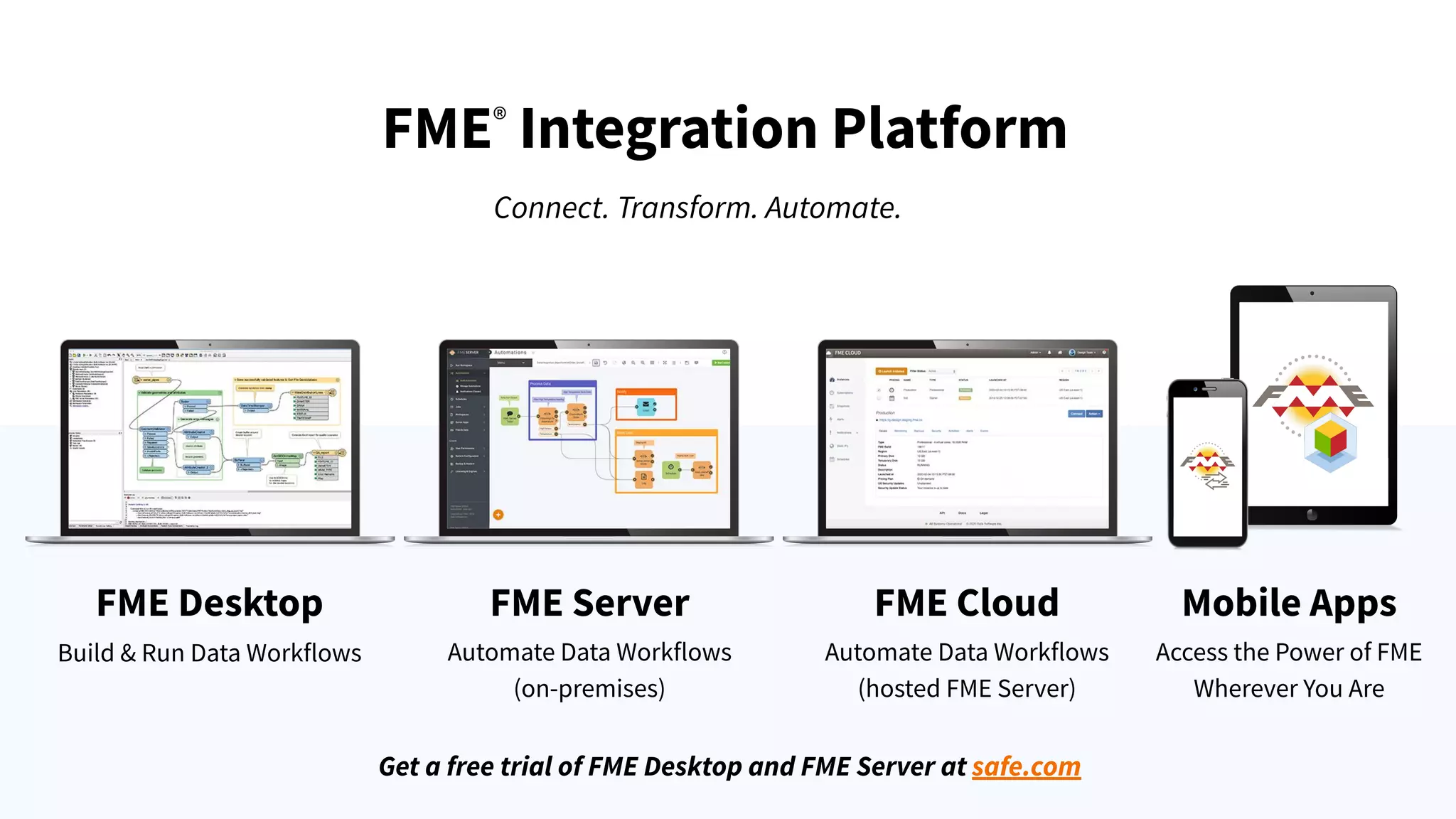

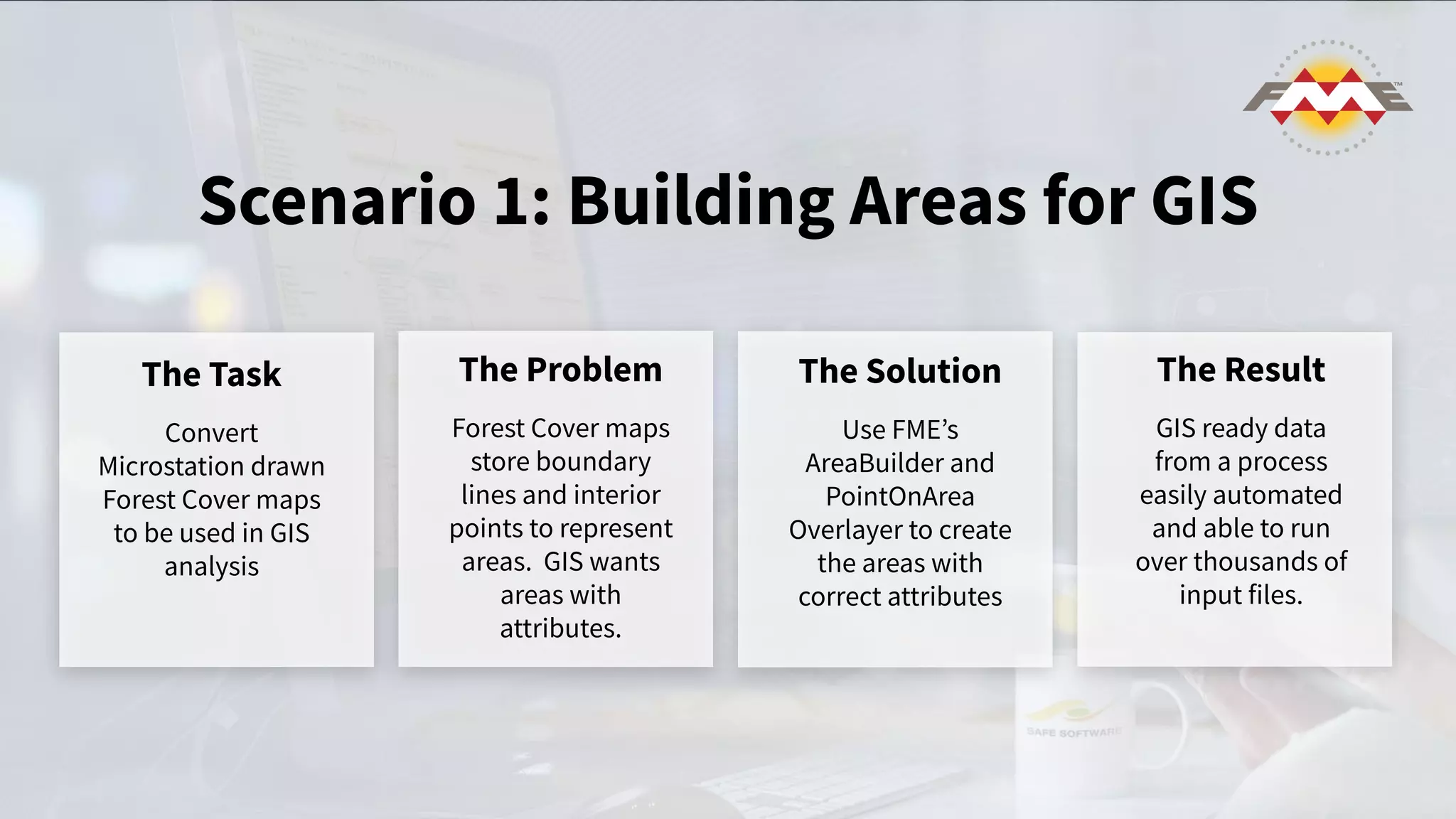
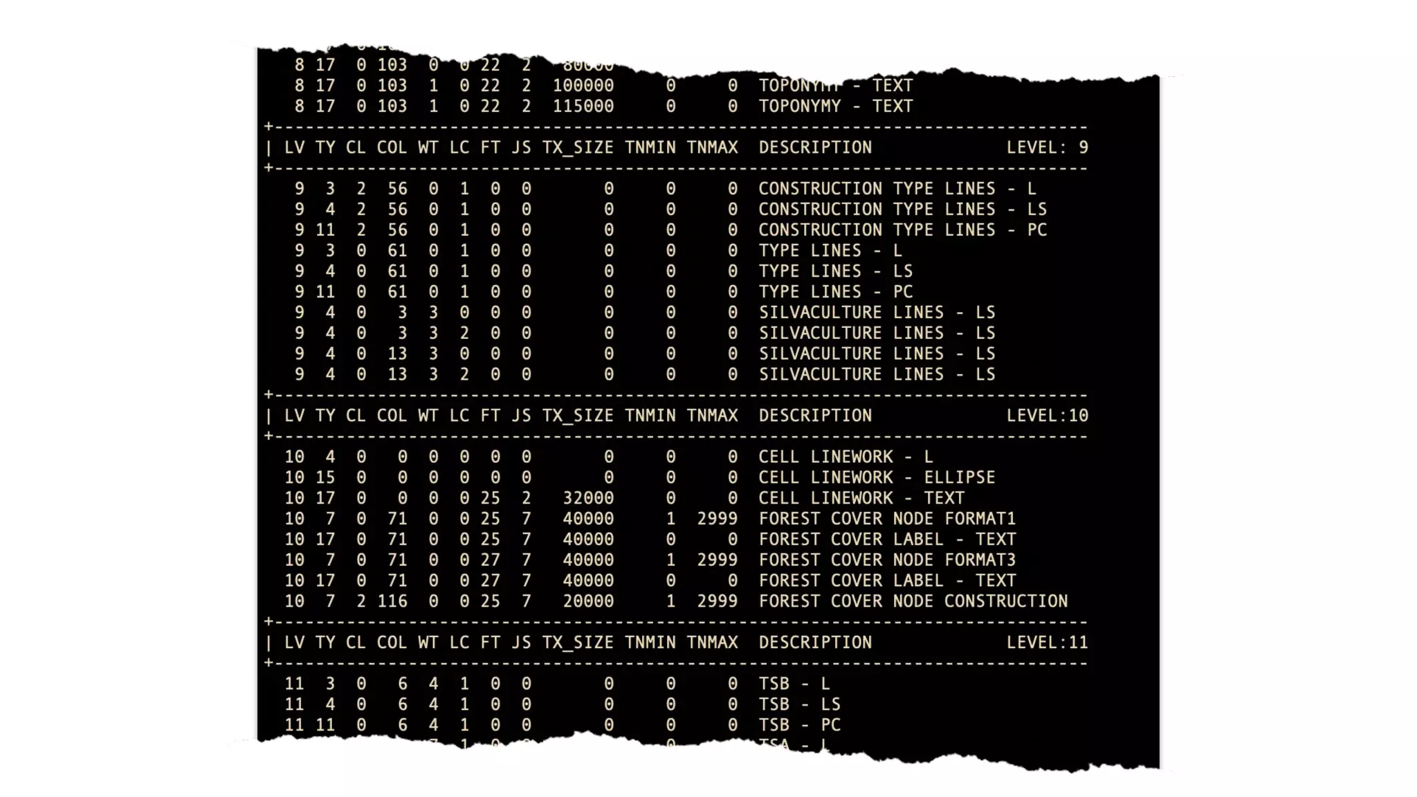
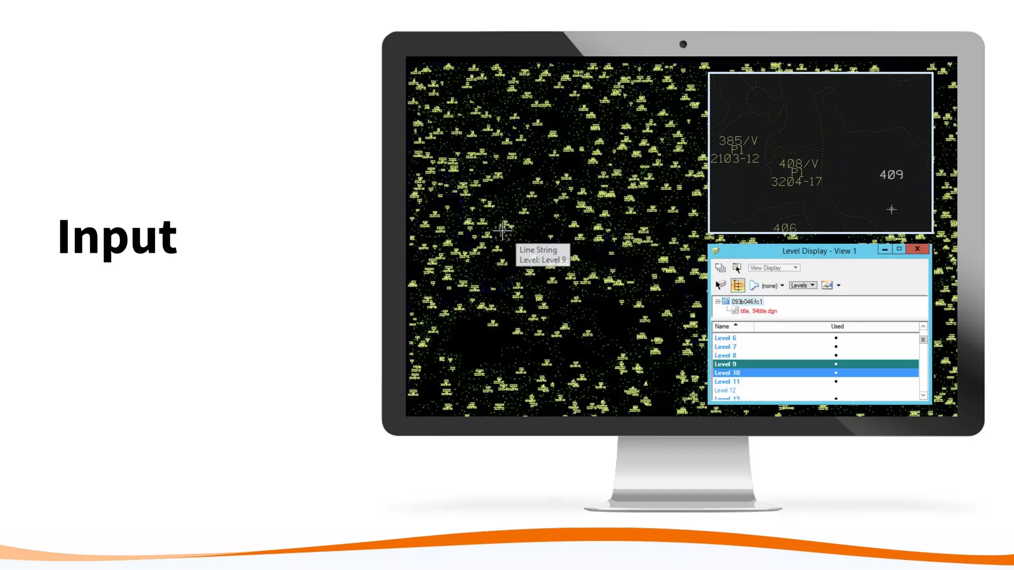
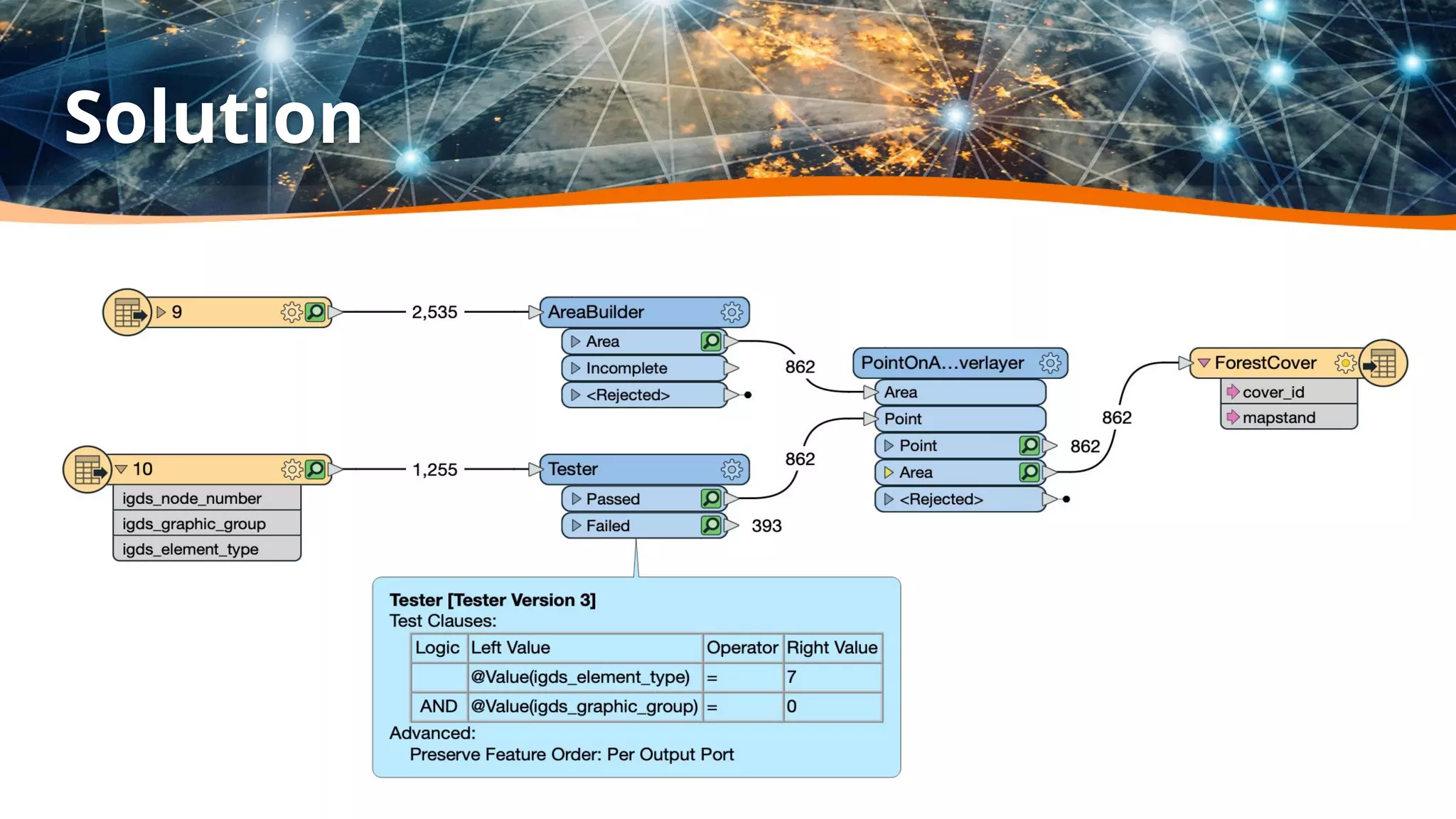
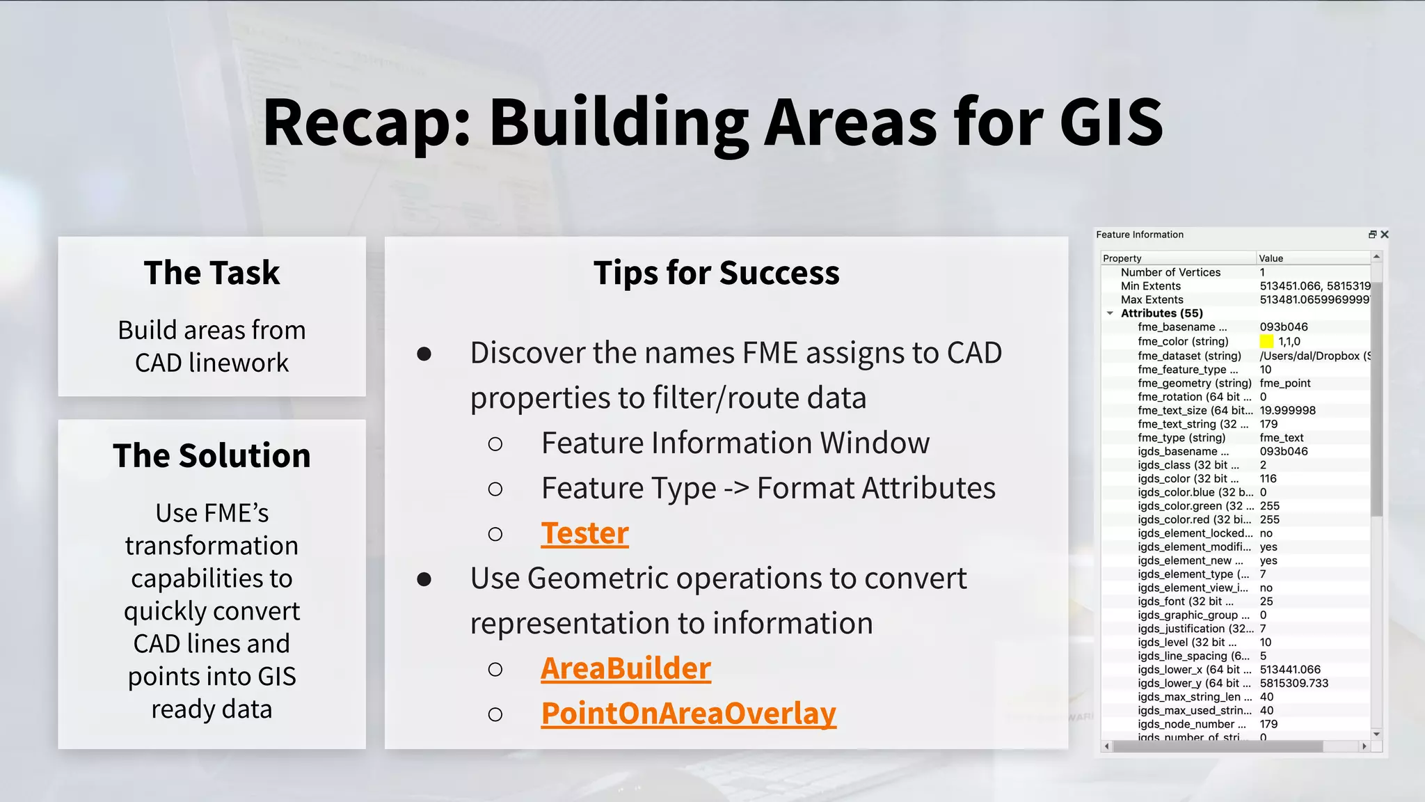

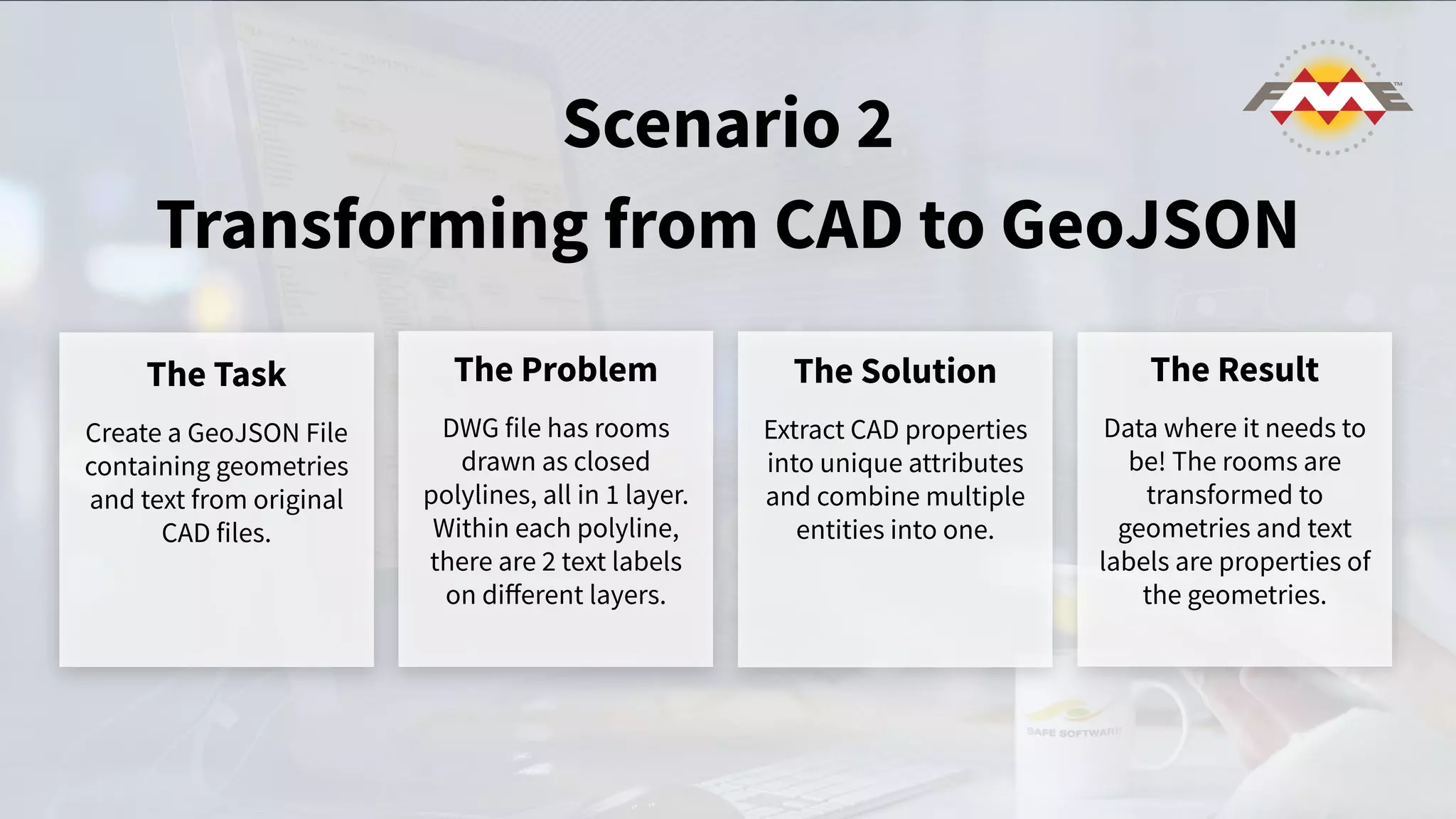

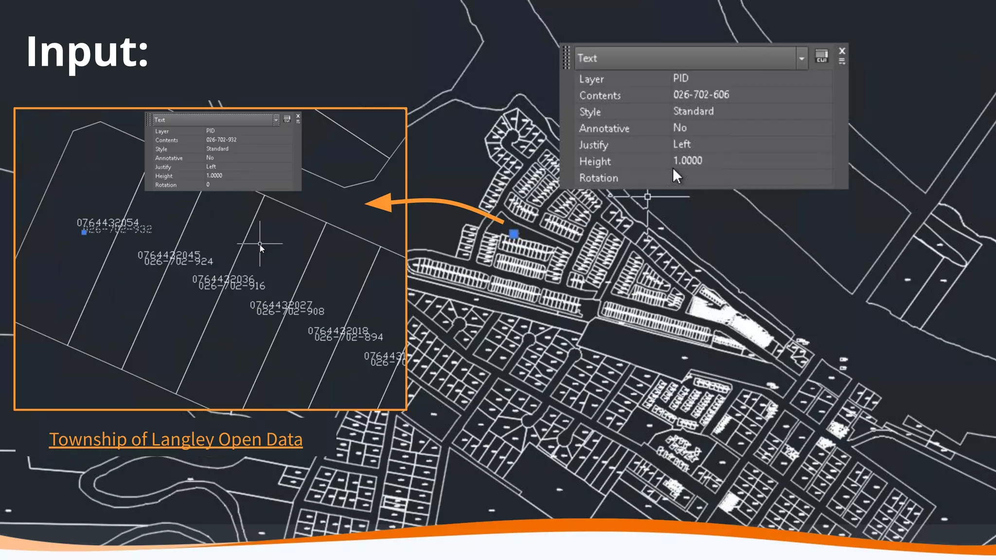
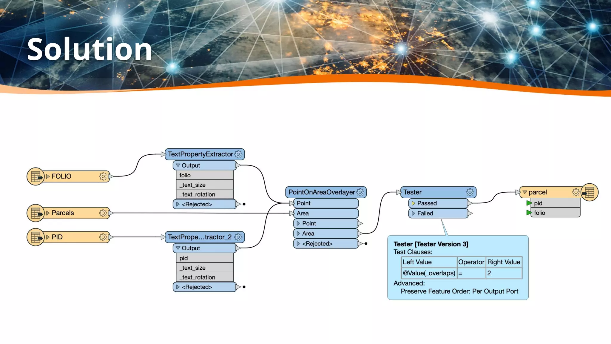
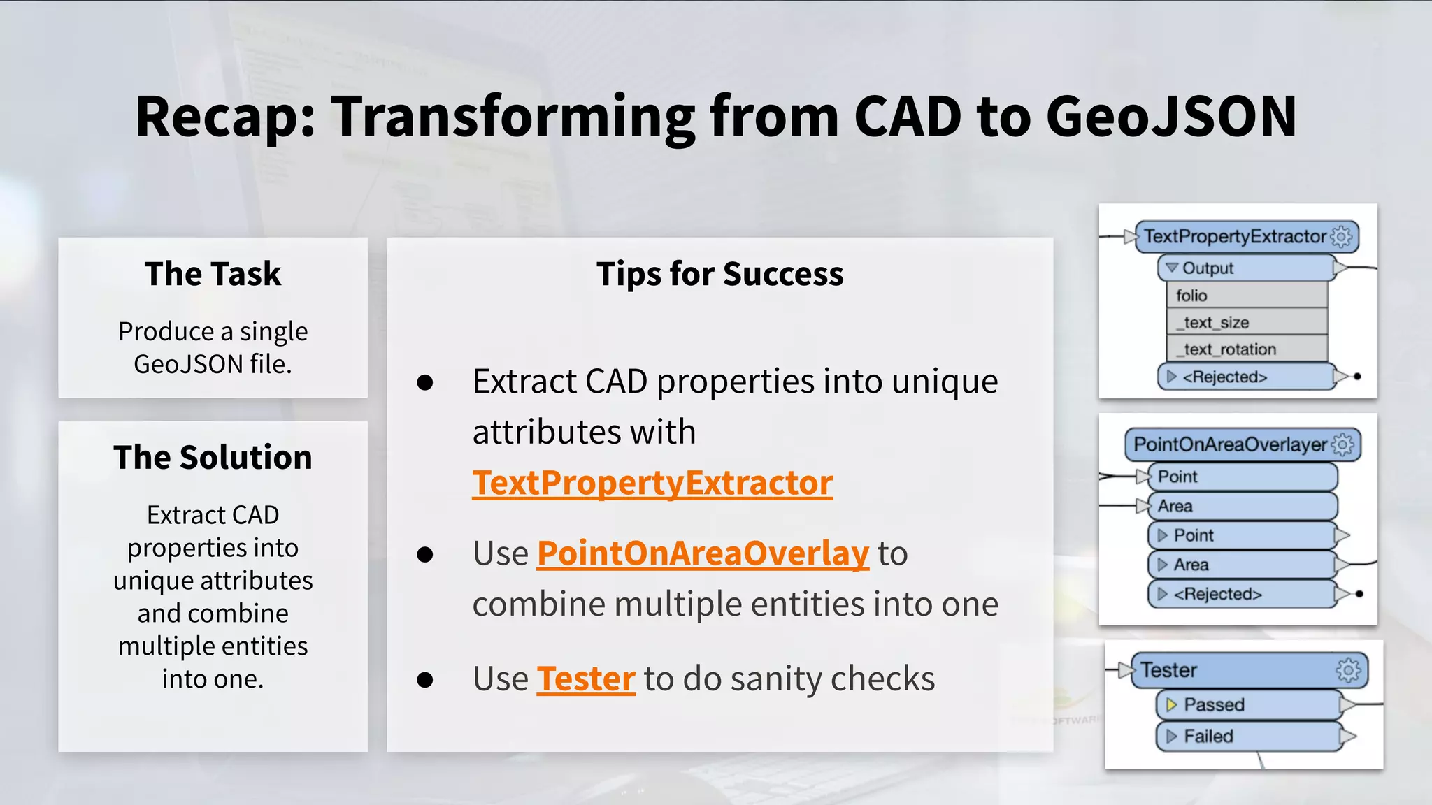
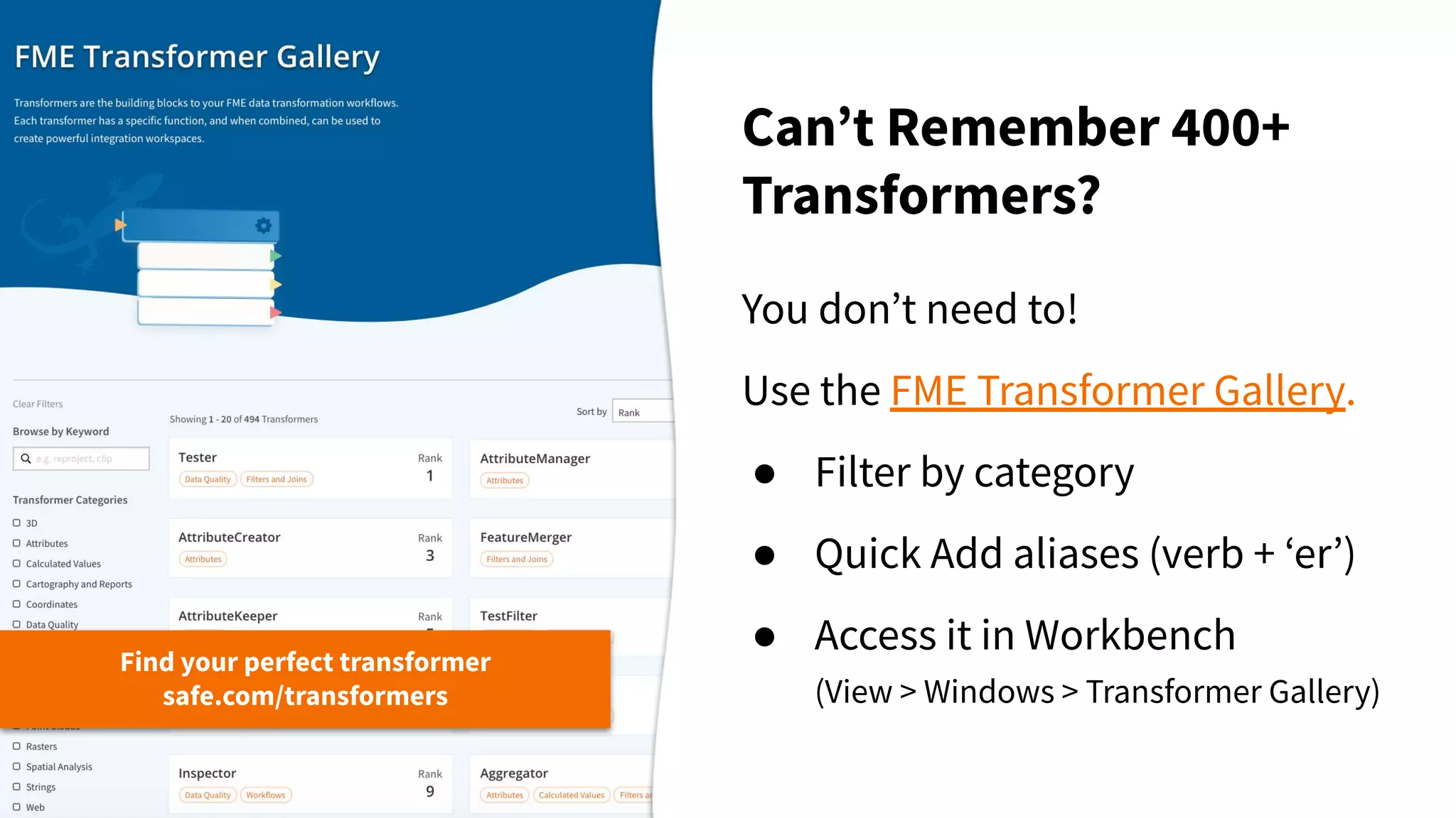

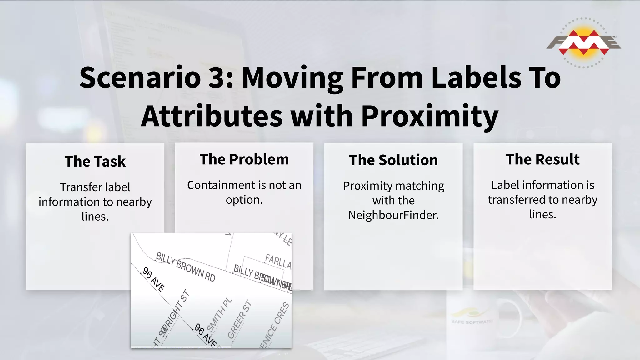
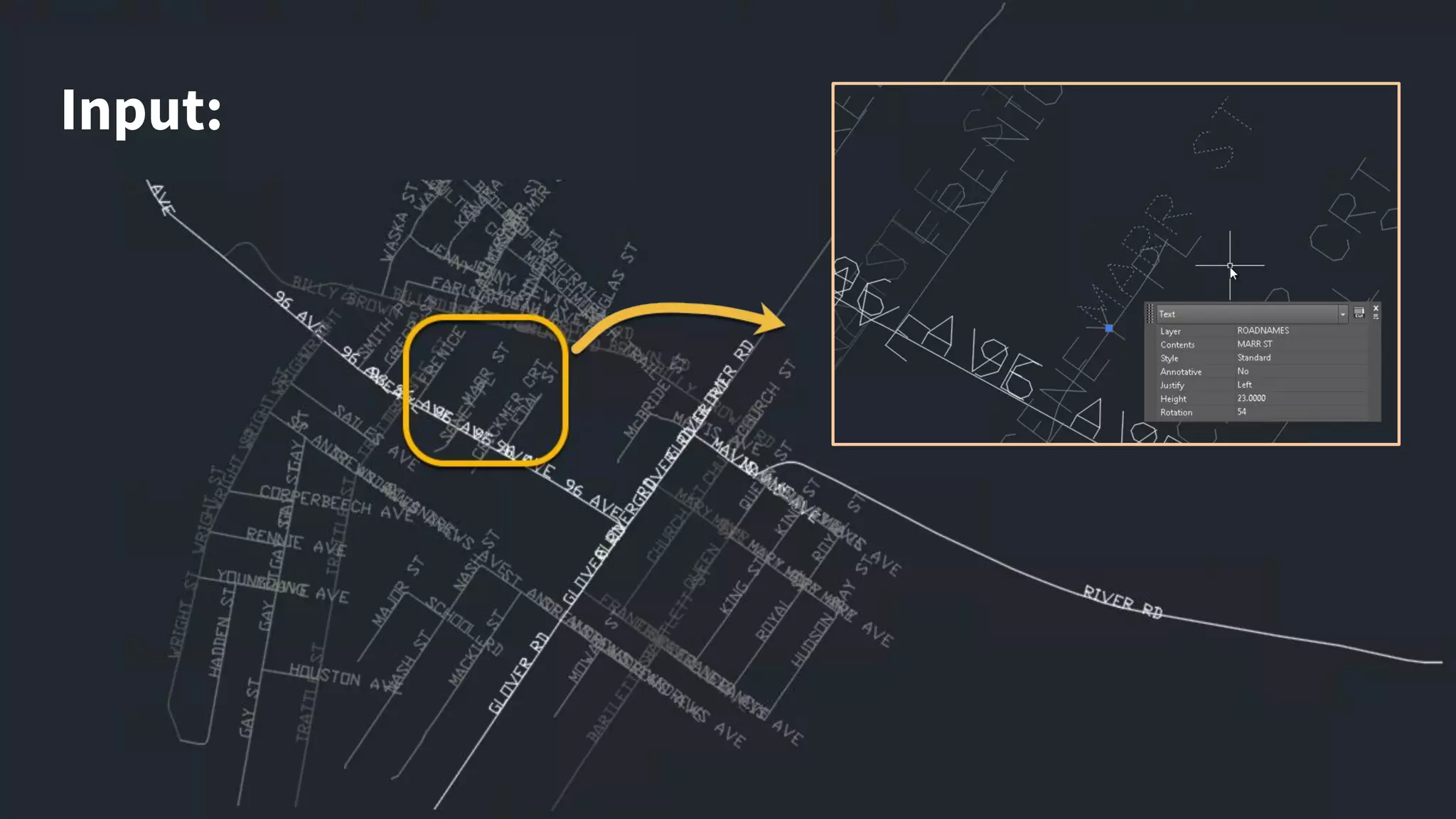
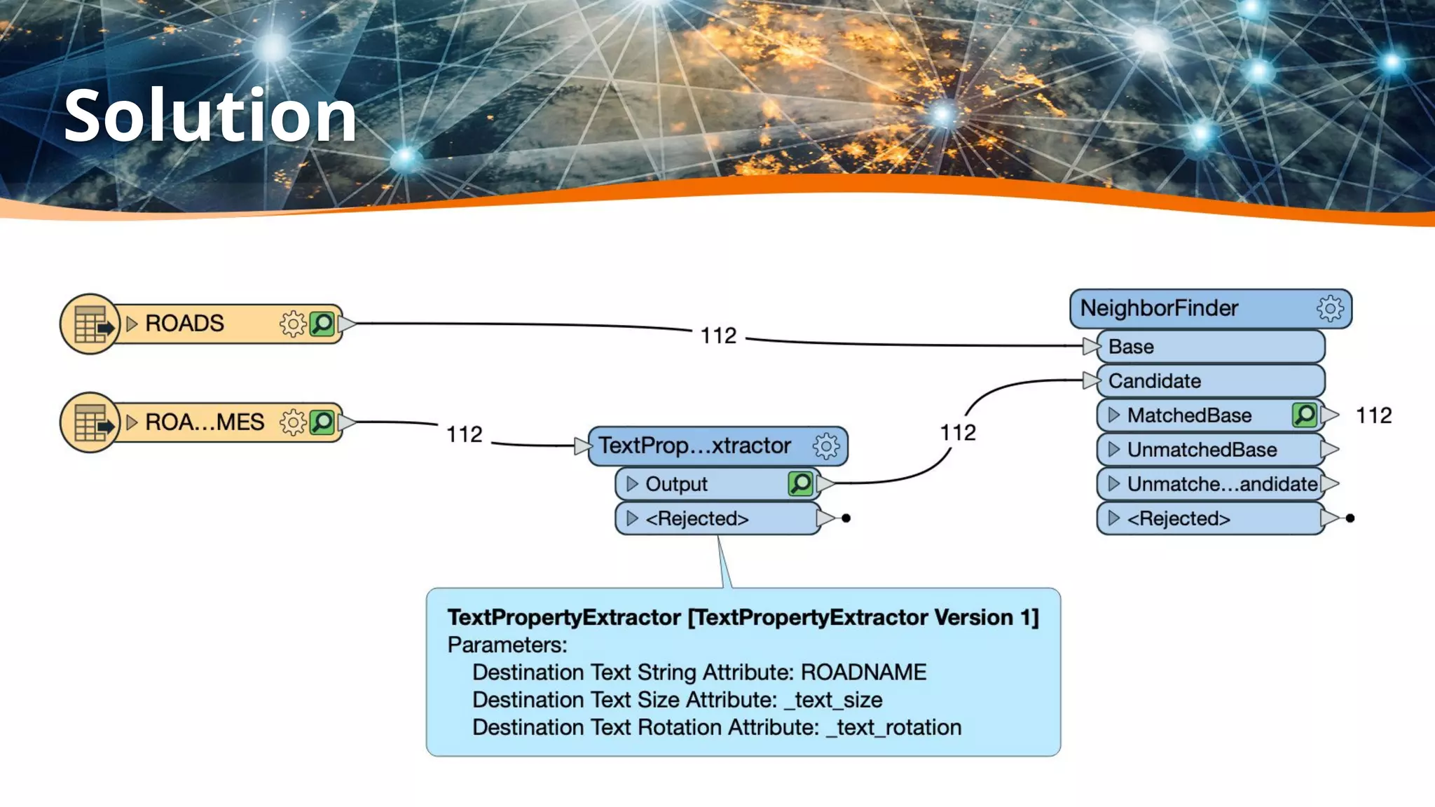
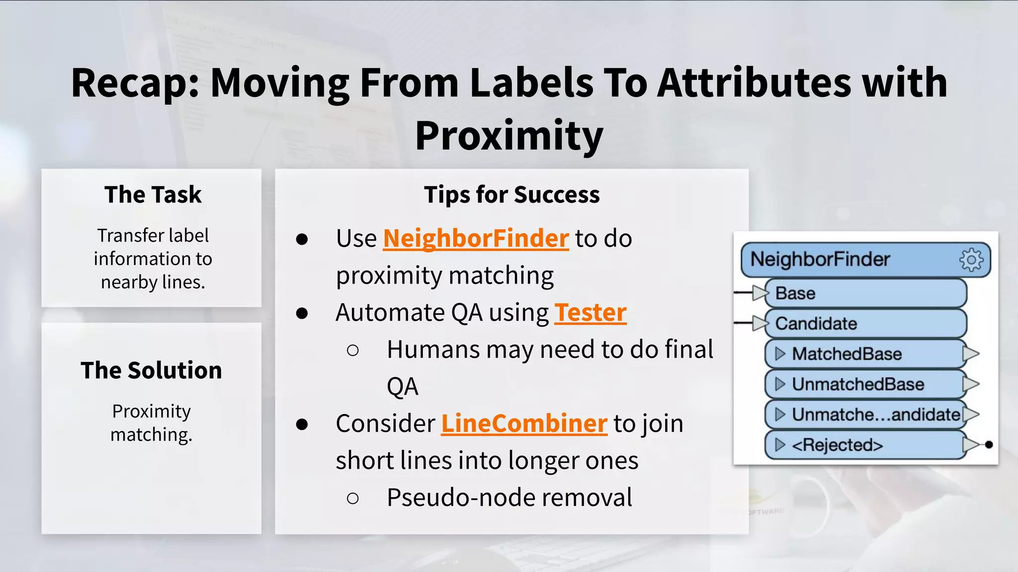


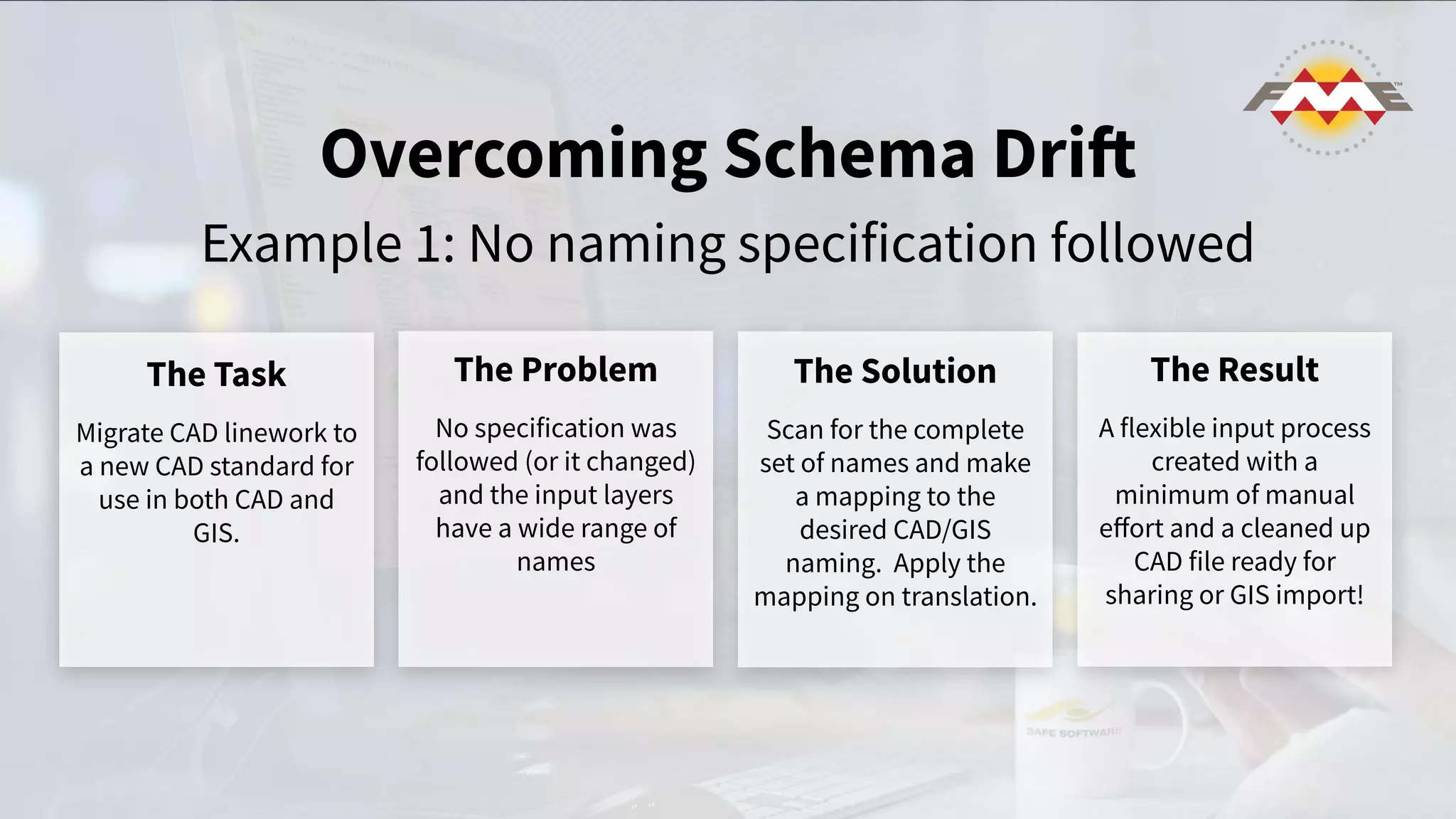
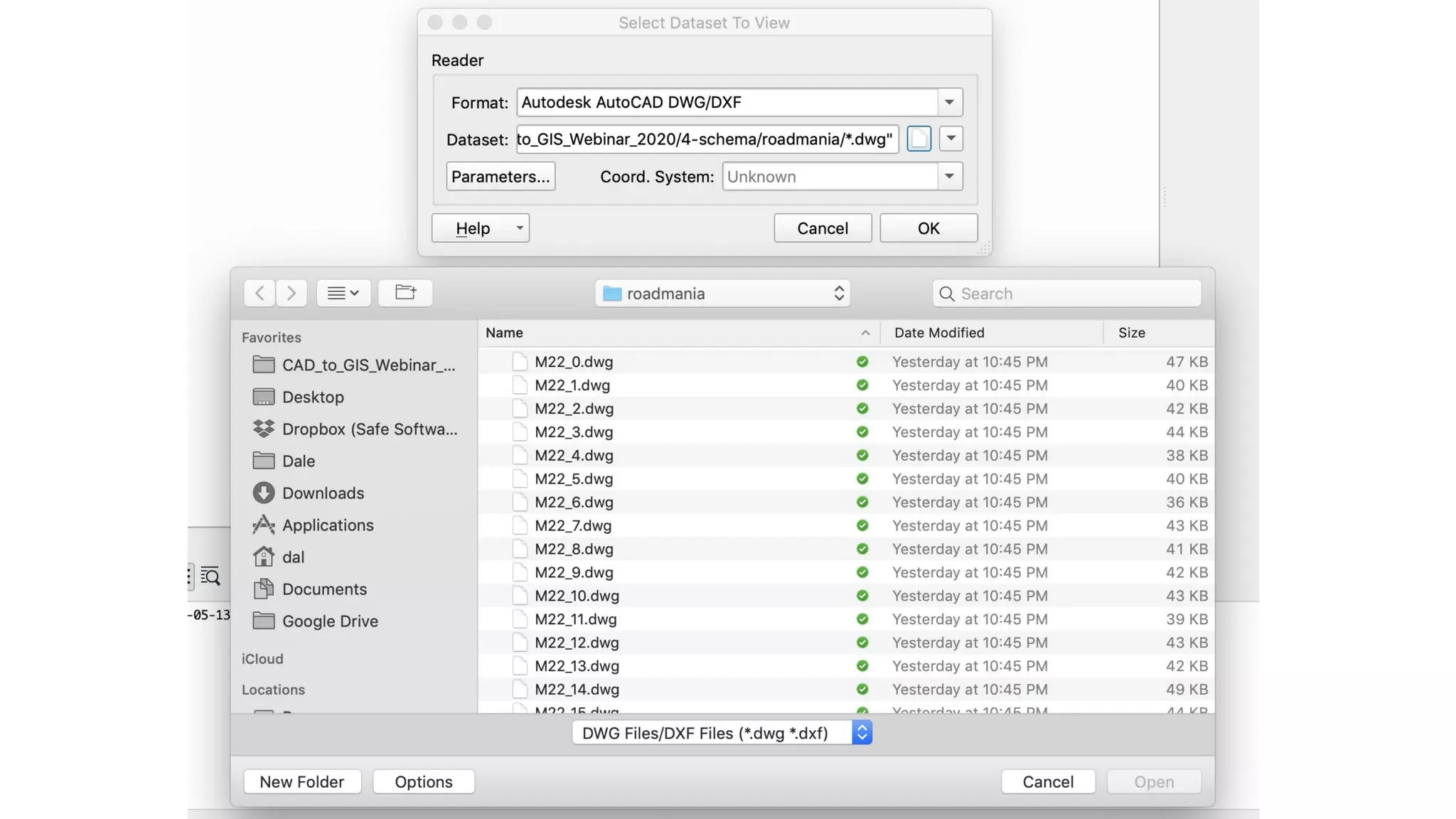

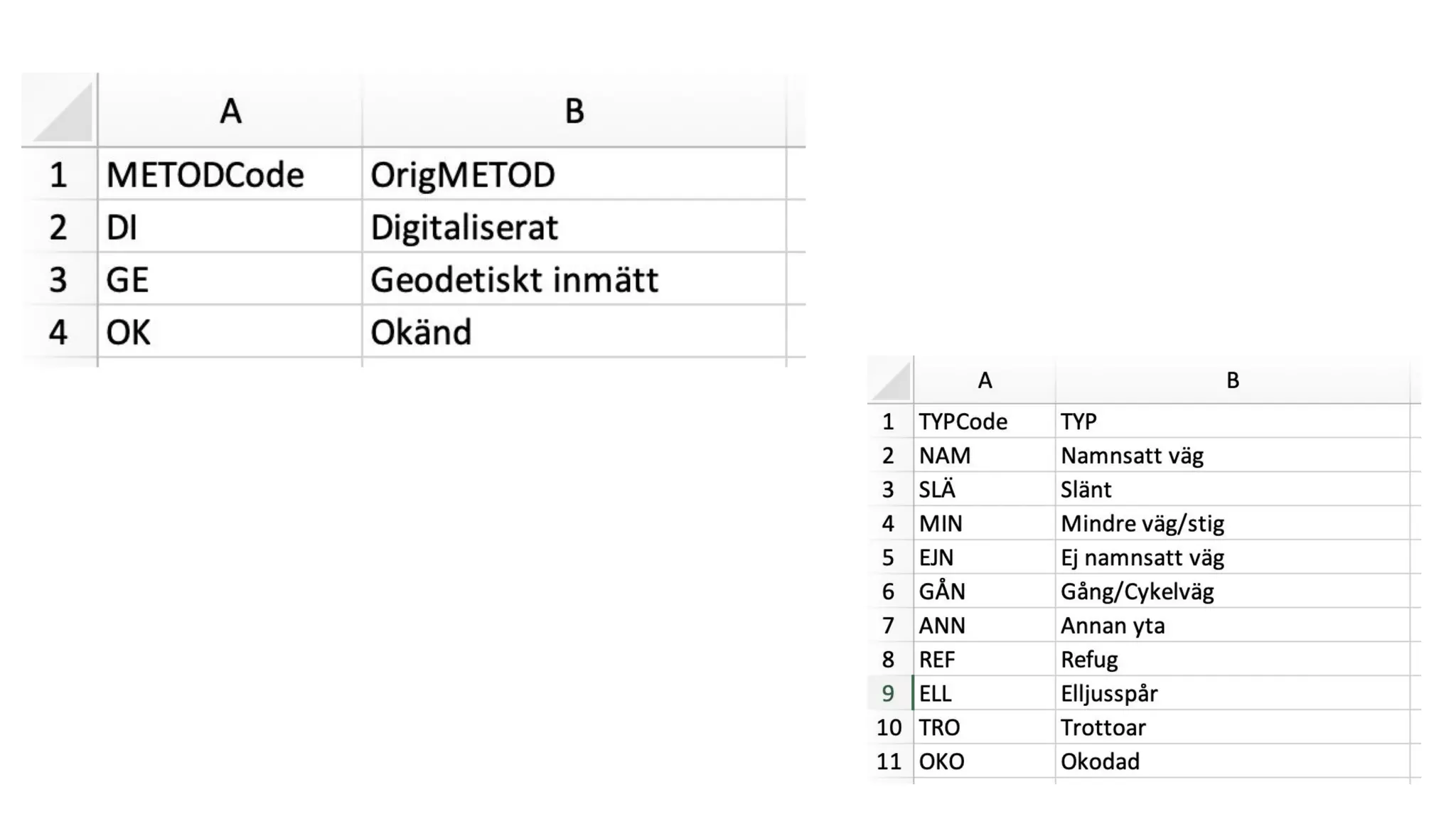
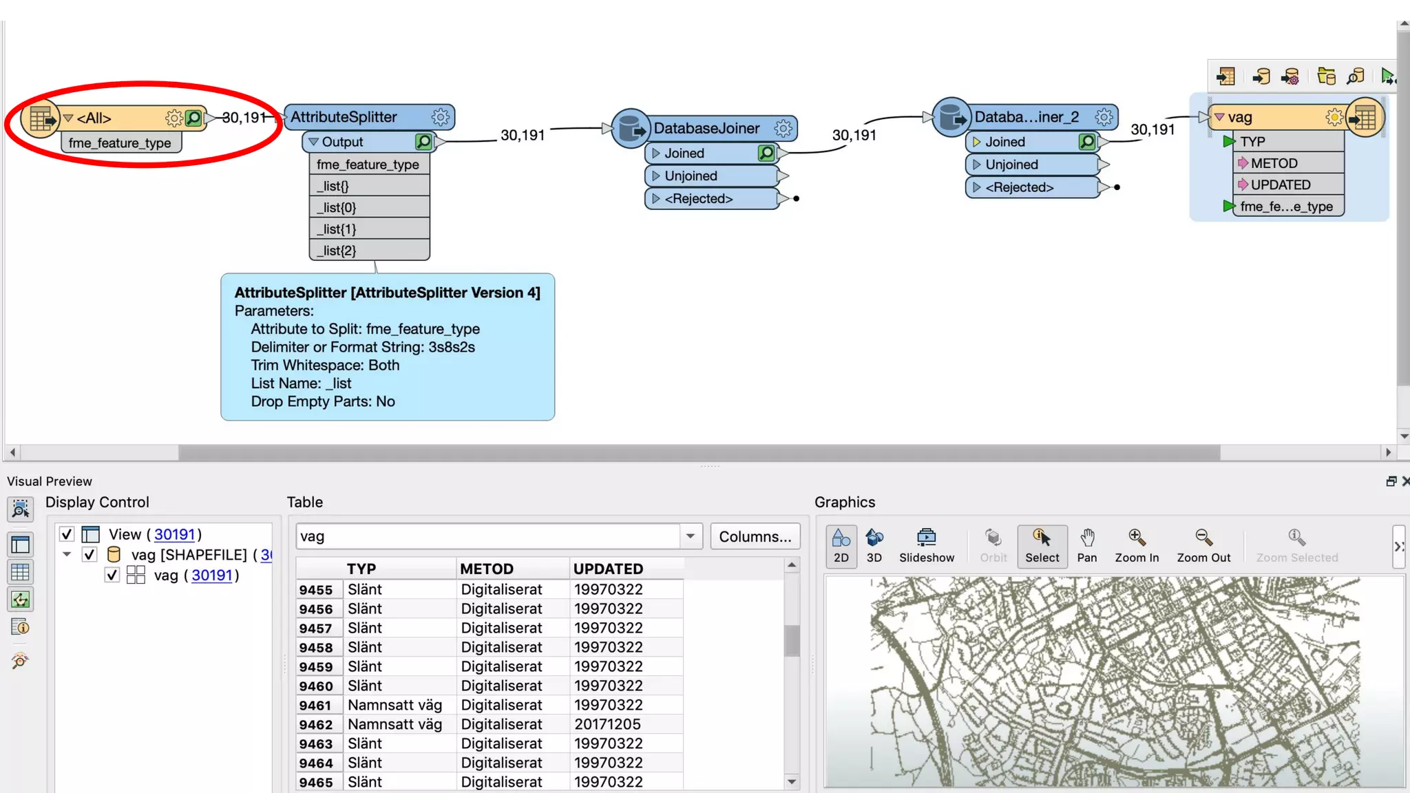
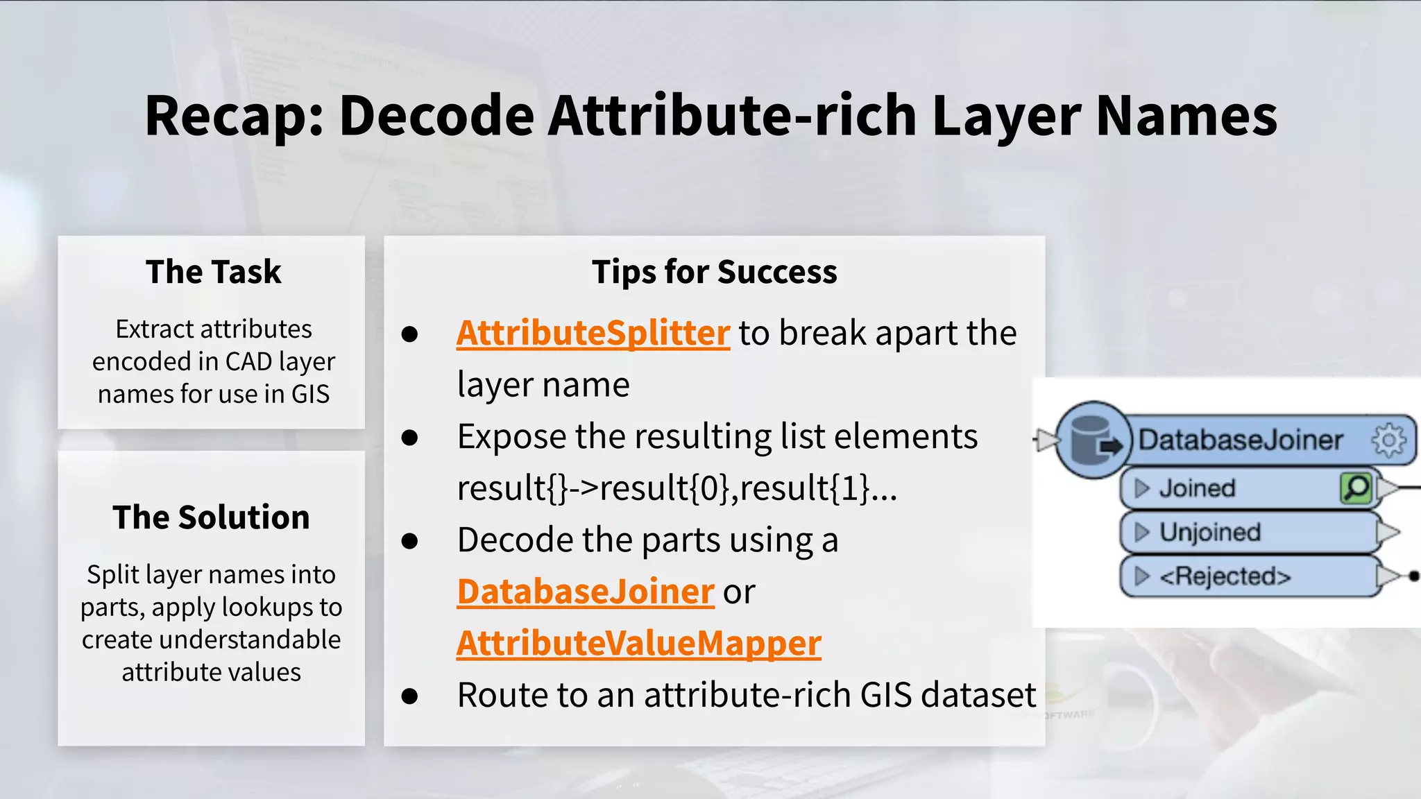

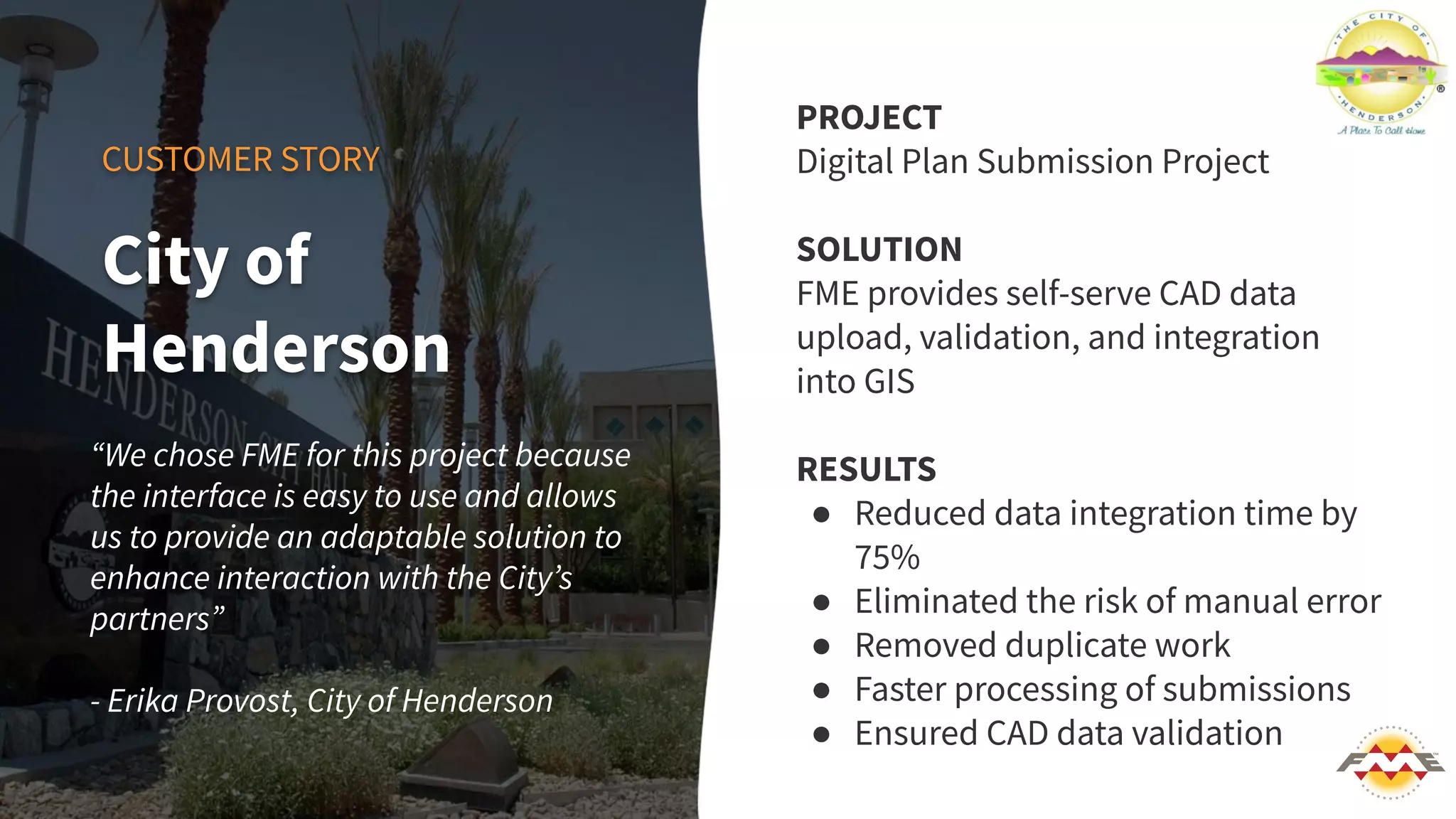
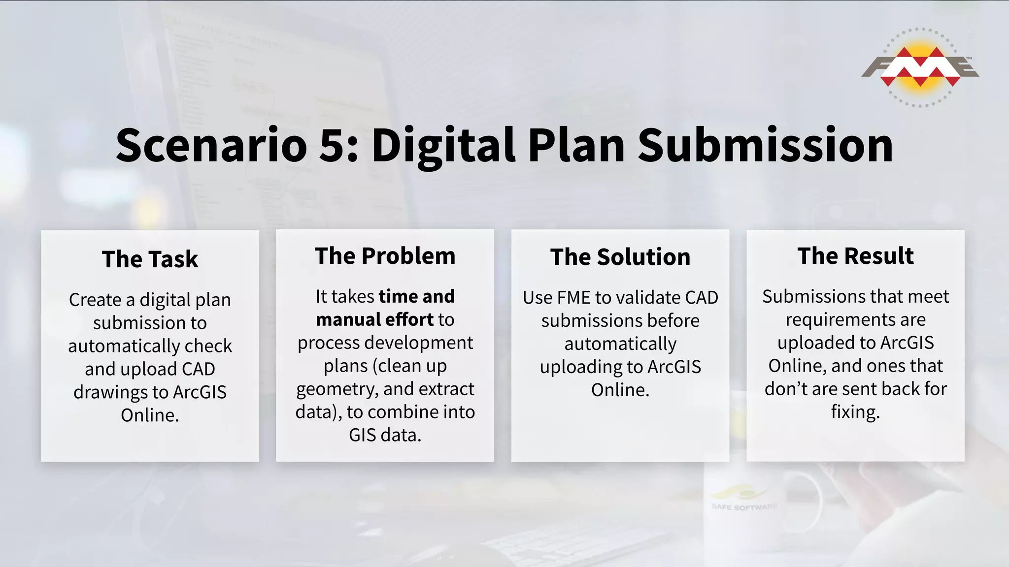
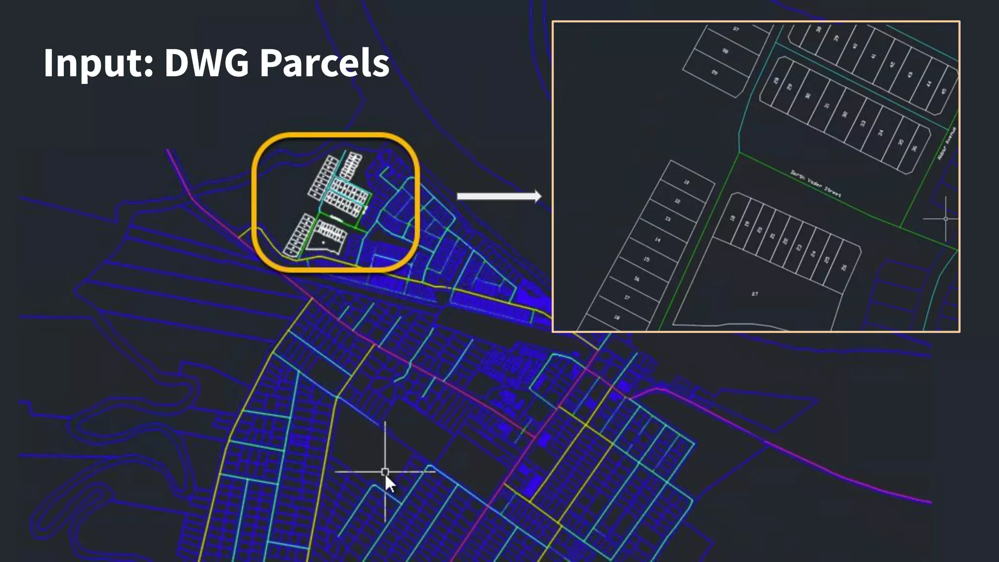
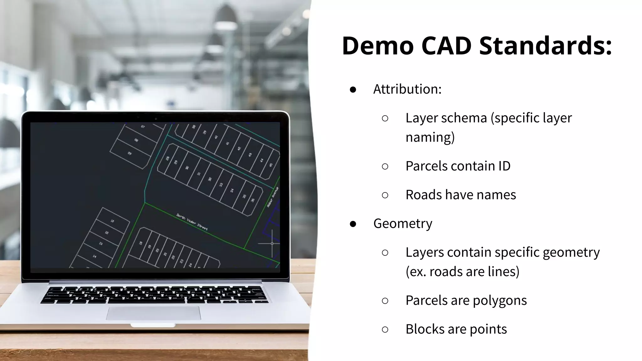


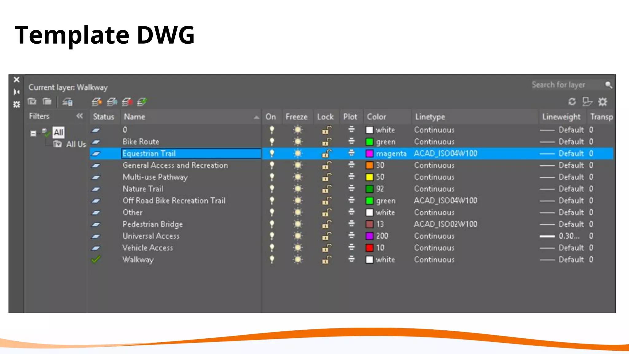
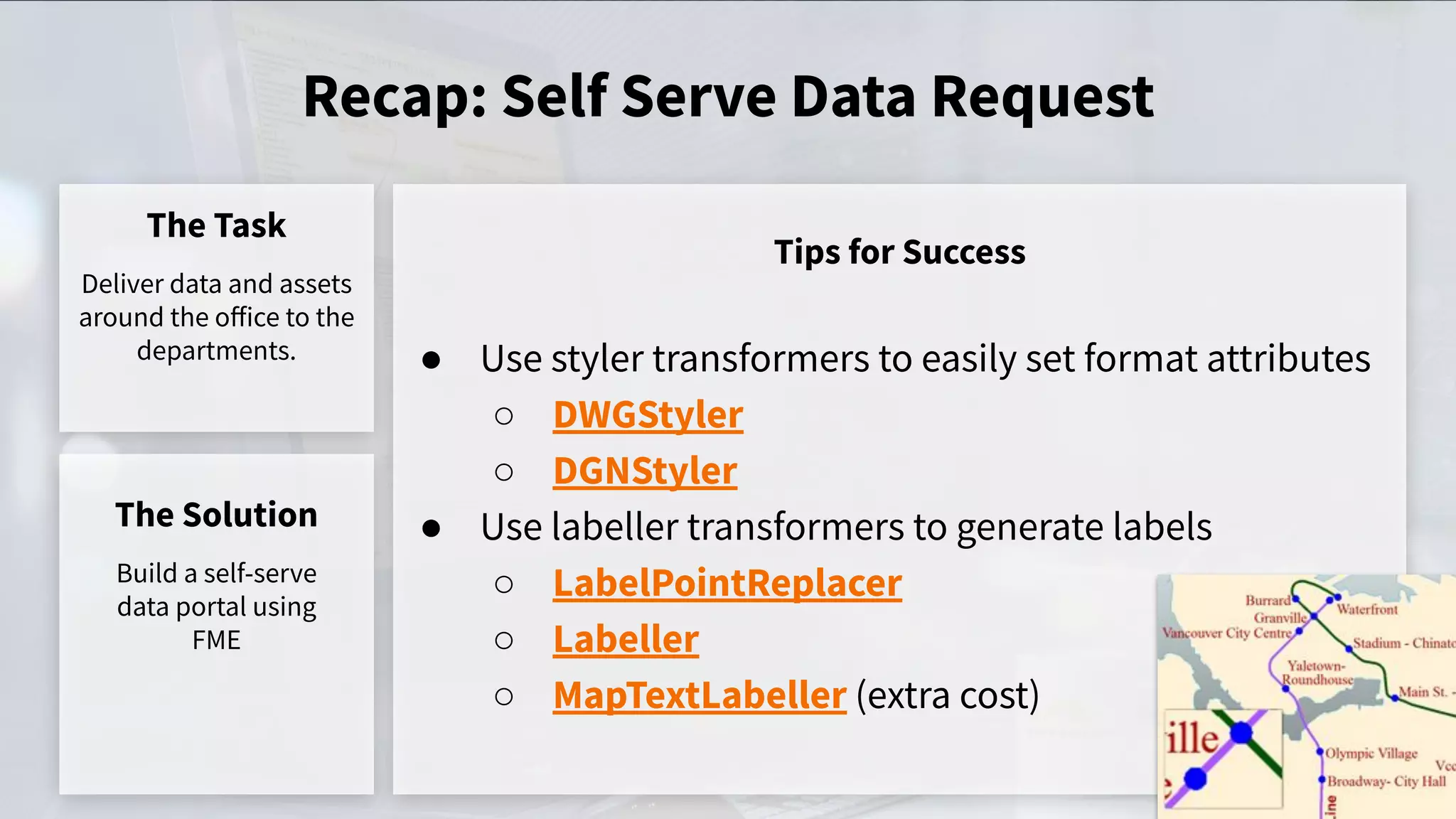
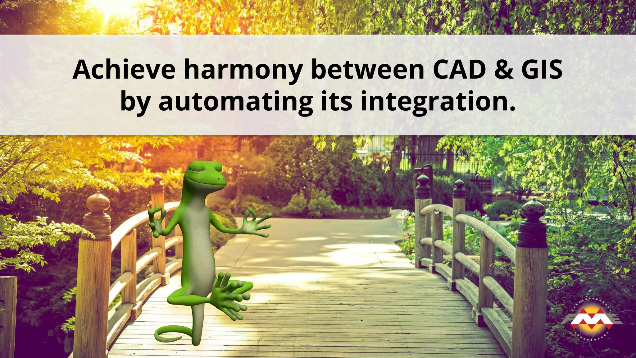
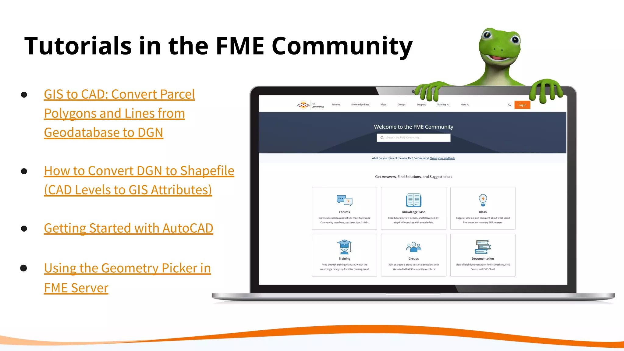


The document presents various strategies for automating the integration of CAD and GIS data, addressing challenges such as data migration, schema drift, and data validation. It highlights the use of FME tools to streamline processes and improve collaboration between CAD and GIS users. Several scenarios illustrate the successful implementation of these solutions, showcasing enhanced efficiency in data handling and user accessibility.


![Support, Monitoring, Continuous Improvement & Scaling Agentic Automation [3/3]](https://cdn.slidesharecdn.com/ss_thumbnails/agenticcommunityseries-day3-cfd-251120170304-ddef8112-thumbnail.jpg?width=640&height=640&fit=bounds)
