The document summarizes research on modifying the formation of multiple input multiple output (MIMO) antennas to improve gain. It investigates different 2x1 and 2x2 MIMO antenna configurations by changing substrate shapes and patch placement. The best 2x1 configuration was an inverted design with high gain up to 6.51 dB and 40 GHz bandwidth. Eight 2x2 configurations were also tested, with the plus-shaped, loop, and chair-shaped designs showing maximum gain improvements of 2.73 dB, 1.17 dB, and 0.92 dB respectively, compared to a single antenna. The proposed MIMO antennas could provide high gain without increasing transmitter power for applications like wireless networks and satellite communication.
![International Journal of Electrical and Computer Engineering (IJECE)
Vol. 13, No. 1, February 2023, pp. 531~548
ISSN: 2088-8708, DOI: 10.11591/ijece.v13i1.pp531-548 531
Journal homepage: http://ijece.iaescore.com
The effect of changing the formation of multiple input multiple
output antennas on the gain
Majed Omar Dwairi1
, Mohamed Salaheldeen Soliman2,3
, Amjad Yousef Hendi1
, Ziad AL-Qadi1
1
Department of Electrical Engineering, Faculty of Engineering Technology Al-Balqa Applied University, Amman, Jordan
2
Department of Electrical Engineering Faculty of Energy Engineering, Aswan University, Aswan, Egypt
3
Department of Electrical Engineering, Faculty of Engineering, Taif University, Taif, Saudi Arabia
Article Info ABSTRACT
Article history:
Received Nov 9, 2021
Revised Jul 30, 2022
Accepted Aug 20, 2022
In this paper, different 2×1 and 2×2 multiple input multiple output (MIMO)
antennas were investigated with changing substrate shapes and changing the
placing of the patches on the substrate, all the investigated antennas based
on FR-4 substrate are characterized by 𝑝𝑒𝑟𝑚𝑖𝑡𝑡𝑖𝑣𝑖𝑡𝑦 = 4.4, and loss
𝑡𝑎𝑛𝑔𝑒𝑛𝑡 = 0.02, with a partial ground. The original antenna covered 3.4 to
13.5 GHz. The best simulation results of the proposed 2×1 MIMO antenna
received for 2×1 inverted with high ultra-wideband (UWB) with bandwidth
up to 40 GHz, the received maximum gain was up to 6.51 dB, with an
average gain of more than the original single antenna at about +1.27 dB. The
best of eight 2×2 MIMO antennas configurations that give good results were
shown. The best-received gain compared with a single antenna gain were at
4.2 GHz about +2.73, +1.17, and +0.92 dB for plus-shaped, loop, and
chair-shaped respectively. A comparison between the proposed MIMO
antennas and other reported works were done. The proposed MIMO
antennas give a good maximum gain and are suitable for different narrow
bands within the UWB such as wireless local area network (WLAN),
worldwide interoperability for microwave access (WiMAX), aeronautical
radio navigation (ARN), International Telecommunication Union 8-GHz
(ITU-8), and X-Band applications with the ability to give high gain without
the need to increase the radiated power of the transmitter antenna.
Keywords:
Multiple input multiple output
Released gain
Resonant frequency
Return loss
Ultra-wideband
This is an open access article under the CC BY-SA license.
Corresponding Author:
Majed Omar Dwairi
Department of Electrical Engineering, Faculty of Engineering Technology Al-Balqa Applied University
P.O. Box: 15008 Amman 11134, Jordan
Email: majeddw@bau.edu.jo
1. INTRODUCTION
Nowadays, ultra-wideband (UWB) micro strip antenna design plays an important role in modern
microwave antenna design; researchers give it more attention after UWB (3.1 to 10.6) GHz was licensed by
the Federal Communication Commission (FCC) [1]. The importance of using micro strip antenna is due to its
several advantages compared with other microwave antennas such as low profile, light weight, low cost,
capability of many frequency operations, and ease of integration with microwave integrated circuit. Many
simulation tools were introduced to microstrip antenna design such as: CST, HFSS, FEKO, IE3D, and others
that gave the researchers the possibility to work in this direction and obtain results close to the reality of the
antenna to be manufactured and adjust and improve it before manufacturing, to reach the required antenna
with accuracy and effectiveness. Some different parameters were investigated to determine the operated,
mismatched, and rejected bands such as those which were investigated Soliman et al. [2]. Moreover, to study
the effect of inserting different slots within the patch or ground or both of them, Dwairi et al. [3] proposed](https://image.slidesharecdn.com/v5426491emr30jul229nov21nn-221121064627-89bd6d4e/75/The-effect-of-changing-the-formation-of-multiple-input-multiple-output-antennas-on-the-gain-1-2048.jpg)
![ ISSN: 2088-8708
Int J Elec & Comp Eng, Vol. 13, No. 1, February 2023: 531-548
532
twenty different fractal slots shaped on the patch studying the effect of these slots on the operating bandwidth
and decreasing the patch area, in addition, to studying the effect of their different fractal slots on the different
parameters. Soliman et al. [4] were investigated a compact UWB antenna using different ground slots to
enhance the operating bandwidth, the authors received bandwidth up to 31.1 GHz with a relative bandwidth
of about 164%. Alotaibi and Alotaibi [5] a triple-band notched filter was proposed using different slots
shaped were used U, T, and L-shaped slots used for worldwide interoperability for microwave access
(WiMAX), wireless local area network (WLAN), and X-Band used respectively to achieve the desired notch
filer. Al-Dwairi [6] proposed for filters with different slot configuration on the patch, feed, and the ground
receiving reject filters for WiMAX operating bandwidth 93.3-3.7GHz, aeronautical radio navigation (ARN)
operating bandwidth 4.2 to 4.5 GHz, WLAN operating bandwidth 5.15 to 5.825GHz, and X-Band (a segment
of the superhigh-frequency radio spectrum that lies between 5.2 GHz and 10.9 GHz and is used especially for
radars and for spacecraft communication, our investigating bandwidth 7.25 to 7.75). Al-Dwairi et al. [7]
proposed five band notched filters using U, S, and ∑-shaped on the patch, feed, and ground receiving
WiMAX, ARN, WLAN, X-Band, and the International Telecommunication Union 8-GHz (ITU-8). In
[8]–[11] the authors use different slots in the patch of the antenna or in its ground or on both, which were
inserted to eliminate unwanted narrow frequency bands within the operating UWB, known as filters,
receiving 3, 4, and 5 notched filters, such as in [10] received four rejection band filters using a very small
factor UWB microstrip antenna are proposed to be used in internet of things (IoT), and in mobile
communication, receiving five rejection bands for bandwidth from 3.5 to 8.2 GHz.
Multiple input multiple output (MIMO) antennas were introduced to micro strip antenna to improve
the data throughput, range, and gain for the received antenna without the need to increase the transmitted
power or its bandwidth, many works concentrated on this type of design such as Weng and Chu [12] were
choosing an optimized size and location of the slot on the feeding line receiving a high gain MIMO antenna
that is designed for mm-wave applications. The most challenging thing for MIMO antennas designer is the
mutual coupling effect that changes the input impedance of the individual antenna elements in an array and
therefore, changes the pattern of the antenna operation and degrades the performance of the array. Many
techniques and methods to reduce the mutual coupling depending on the application of the investigated
antennas and the way of excitation have been produced.
Alibakhshikenari et al. [13] produced a 2×2 MIMO antenna operating in three narrow bands from
2.11-4.42 GHz with reduced mutual coupling by implementing a proper slot on the partial ground and
increasing the efficiency up to 73% on the resonant frequencies. Alibakhshikenari et al. [14], [15] produced
different aperture-coupling and defected ground structures (DGS) to increase the insulation from the patch
and the feeding element; in [14] the aperture-coupling was used to isolate the micro strip by inserting
T-shaped and orthogonally around the squared patch, the produced antenna is applicable for WLAN
communication, while in [15] two circular patch antennas are closely placed to each other and inserted
H-shaped DGS on the ground that highly decreases the mutual coupling, producing MIMO antenna that
operates at 5.3 GHz frequency, which can be used for Wi-Fi and WiMAX. Microstrip antennas have various
applications for wireless communication systems using different microstrip antenna designs and
configurations for different applications.
Alibakhshikenari et al. [16] designed a 4-pair conformal micro strip MIMO antenna consisting of
eight cells each operating in ka-band (35 GHz), resulting in a reduction of the side lobe at the same time of
increasing the bandwidth; the simulated and measured results conformed. Alibakhshikenari et al. [17]
introduced a 5G handset mobile communication antenna using a compact 2×2 MIMO patch antenna that
characterizes by a super wideband starting from 2.97 to 19.82 GHz, this proposed antenna achieved a gain of
more than 8 dB. Swamy and Siddaiah [18], a 4-element MIMO patch antenna with inset line feeding was
investigated for narrowband from 27 to 28.95 GHz. The received results proved a reduction of BER at the
same time increasing the signal to noise ratio, and the resulting gain received was about 6.14 dB, with the
perspective to use this produced antenna for 5G mobile handset antenna application. Li et al. [19], a modified
pentagonal micro strip antenna was investigated and introduced a high gain of about 6.17 dB with a
perspective to be used for 5G applications. Khan et al. [20], the author shows that the gain improvement of
the proposed 2×2 MIMO antenna were from 1 to 2.5 dB, that has been achieved compared to the single patch
antenna. Alibakhshikenari et al. [21] proposed UWB antenna to exhibit excellent radiation characteristics,
using F and T-shaped slots on the ground and the arms respectively, receiving relative bandwidth of about
173% and a maximum gain 3.5 dBi.
Alibakhshikenari et al. [22] a very useful survey was presented with a comprehensive study of
deferent methods with different isolation based on meta surface inspired and metamaterial for antennas and
analyze each of the presented methods. In [23] reduced unwanted mutual coupling for 34 by 34 antenna array
by using substrate-integrated-waveguide (SIW) for operating at THz band, which is realized by interjecting
metallic via-holes between the radiating elements to block propagating surface waves. Alibakhshikenari et al.](https://image.slidesharecdn.com/v5426491emr30jul229nov21nn-221121064627-89bd6d4e/75/The-effect-of-changing-the-formation-of-multiple-input-multiple-output-antennas-on-the-gain-2-2048.jpg)
![Int J Elec & Comp Eng ISSN: 2088-8708
The effect of changing the formation of multiple input multiple output antennas on … (Majed Omar Dwairi)
533
[24] used metamaterial photonic bandgap techniques to reduce mutual coupling which is simple and
effective. Alibakhshikenari et al. and Wang et al. [25], [26] an effective technique is used for suppressing the
mutual coupling based on a metamaterial (MTM) electromagnetic bandgap. Alsaif [27] a UWB microstrip
antenna has been proposed for portable wireless devices based on a simplified composite right/left-hand
transmission line, this antenna was implemented using F and T-shaped slots in the patch radiator, the
operating bandwidth operates from 0.6 to 9.2 GHz giving relative bandwidth of about 173.6% and gains
about 4 dBi. Proposed and investigated important antennas works based on metamaterials, for UWB portable
microwave devices and wireless communications [28]–[30].
In this paper, an UWB antenna based on [8], was optimized to operate at UWB, then the authors
inserted some slots within the patch and the feed line to reject WLAN and X-bands. The proposed antenna in
[8] is a good candidate for our investigation to be modified to MIMO scenarios with 2×1 and 2×2, with
different modifications to compare these MIMO antennas and discover which gives the best gain. The
remainder of this work has been organized as follows: section 2 single antenna design, next section 3
simulation results of 2×1 and 2×2 MIMO antennas; section 4 discussion of the received results. Finally,
conclusions and future work were discussed in section 5.
2. ANTENNA DESIGN
The investigated UWB micro strip patch antenna based on [8], is presented in Figures 1(a) to (c), the
substrate is built on FR4 with relative permittivity equal to 4.4 and loss tangent equal to 0.02. The antenna
dimensions are listed in Table 1. In order to improve the patch antenna bandwidth and its matching inserted
an arc cut of radius R mm at the corners of the rectangular patch antenna and the cutting polygonal slot in the
ground, which in turn neutralized the capacitive and inductive reactance receiving a pure resistive input
impedance [8]. The best slot cut circles at the rectangular angles are R1=R2=R3=R4=2 mm. The polygonal
dimensions are listed in Table 1. This produced antenna will be modified to different 2×1 and 2×2 MIMO
antennas and all the comparisons of the investigated MIMO antennas will be referred to this original antenna
in point of view return loss and the released gain.
Table 1. Antenna parameters
Length [mm] Width [mm] Height [mm]
Substrate Ls= 35 Ws =30 Hs =1.6
Patch antenna Lp =14.5 Wp =15 tp = 0.009
Feed line Lf = 13.5 Wf = 2.85
Ground Lg = 12.5 Wg =30
Ground slot polygonal shape with w = 3mm, L =0.75mm and L1= 1mm
(a) (b) (c)
Figure 1. The investigated antenna: (a) side view, (b) front view, and (c) back view
3. SIMULATION RESULTS
The simulation of the investigated single antenna and the all-proposed MIMOs antennas has been
carried out using CST-EM simulator 2018, where all the investigated antennas are based on the reference
antenna introduced in [8]. The investigation started with the simulation of the original antenna followed by
the three proposed 2×1 MIMO antennas designed and the results. Finally, an investigation of the eight
proposed 2×2 MIMO antennas designed and results.](https://image.slidesharecdn.com/v5426491emr30jul229nov21nn-221121064627-89bd6d4e/75/The-effect-of-changing-the-formation-of-multiple-input-multiple-output-antennas-on-the-gain-3-2048.jpg)
![ ISSN: 2088-8708
Int J Elec & Comp Eng, Vol. 13, No. 1, February 2023: 531-548
534
3.1. Single antenna results
Equations should be placed at the center of the line and provided consecutively with equation
numbers. The investigated single antenna based on [8], shown in Figure 1. The simulation results of the
return loss (S11), voltage standing wave ratio (VSWR), and the released gain are shown in Figures 2 to 4.
The operating bandwidth for all proposed antennas has been from 2 to 15 GHz.
Figure 2. The simulated return loss for the single
antenna
Figure 3. The simulated VSWR for the single
antenna
Figure 4. The simulated released gain for the single antenna
3.2. 2×1 MIMO antenna results
Three different 2×1 antenna configuration was investigated based on changing the dimensions of the
substrate and the location of the patch antenna on the substrate. The investigated are shown in Figures 5(a) to
5(c), where the first 2×1 antenna was introduced as inverted MIMO, the second 2×1 was introduced as mirrored
MIMO, and finally, the third 2×1 antenna was introduced as nearby MIMO. For all the investigated 2×1 MIMO
antennas we found the return loss and the gain; which will be later compared in the discussion section.
3.2.1. 2×1 Inverted MIMO antenna
The proposed 2×1 inverted MIMO antenna is the modified single antenna substrate dimension
(2Ws+2mm×Ls×hs) mm3
, as shown in Figure 5(a). The two antennas are the same dimensions inverted
180 degrees with 2 mm inserted in the substrate width to separate the ground of the two antennas. The
simulation results of the return loss S11, S22, S12, and S21 (where S12, and S21 are the coupling return
loss), and the released gain are shown in Figures 6 and 7 respectively. In Figure 7, it is seen that S11 and S22
are identical and S12 and S21 are identical as well. From S-parameters, it is notable that the bandwidth is
received up to 40 GHz without any mismatched or rejected band; this is the only case that received these
results. From Figure 7, the overall released gain of the bandwidth is good.
2 3 4 5 6 7 8 9 10 11 12 13 14 15
-30
-25
-20
-15
-10
-5
0
S11[dB]
Frequency [GHz]
single ant.
2 3 4 5 6 7 8 9 10 11 12 13 14 15
1
2
3
4
5
6
7
8
9
10
11
12
13
14
15
VSWR
Ferquency [GHz]
VSWR single
2 3 4 5 6 7 8 9 10 11 12 13 14 15
0
1
2
3
4
5
6
7
Released
gain
[dB]
Frequency [GHz]
Max. gain over Ferquency](https://image.slidesharecdn.com/v5426491emr30jul229nov21nn-221121064627-89bd6d4e/75/The-effect-of-changing-the-formation-of-multiple-input-multiple-output-antennas-on-the-gain-4-2048.jpg)
![Int J Elec & Comp Eng ISSN: 2088-8708
The effect of changing the formation of multiple input multiple output antennas on … (Majed Omar Dwairi)
535
(a) (b) (c)
Figure 5. 2×1 MIMO antennas, (a) inverted, (b) mirrored, and (c) nearby
Figure 6. The simulated return loss S11, S22, and
coupling S12, and S21 for 2×1 inverted MIMO
antenna
Figure 7. The simulated released gain for 2×1
inverted MIMO antenna
3.2.2. 2×1 mirrored MIMO antenna
The 2×1 mirrored MIMO antenna is shown in Figure 5(b), the modification is done by doubling the
substrate length, with the same width. The second patch antenna is the same dimensions but mirrors the first.
The simulation results of the return loss S11, S22, S12, and S21, and the released gain are shown in Figures 8
and 9, respectively.
Figure 8. the simulated return loss S11, S22, and
coupling S12, and S21 for 2×1 mirrored MIMO antenna
Figure 9. The simulated released gain for 2×1
mirrored MIMO antenna
2 4 6 8 10 12 14 16 18 20 22 24 26 28 30 32 34 36 38 40
-45
-40
-35
-30
-25
-20
-15
-10
-5
0
Return
loss
[dB]
Frequency [GHz]
S22
S12
S21
S11
2 4 6 8 10 12 14 16 18 20 22 24 26 28 30 32 34 36 38 40
0
1
2
3
4
5
6
7
8
Released
gain[dB]
Frequency [GHz]
Gain over Frequency
2 3 4 5 6 7 8 9 10 11 12 13 14 15
-35
-30
-25
-20
-15
-10
-5
0
Return
Loss
[dB]
Frequency [GHz]
S22
S12
S21
S11
2 4 6 8 10 12 14
0
1
2
3
4
5
Released
gain
[dB]
Frequency [GHz]
Max. gain over Frequency](https://image.slidesharecdn.com/v5426491emr30jul229nov21nn-221121064627-89bd6d4e/75/The-effect-of-changing-the-formation-of-multiple-input-multiple-output-antennas-on-the-gain-5-2048.jpg)
![ ISSN: 2088-8708
Int J Elec & Comp Eng, Vol. 13, No. 1, February 2023: 531-548
536
3.2.3. 2×1 nearby MIMO antenna
The 2×1 nearby MIMO antenna is shown in Figure 5(c), the modification is done by doubling the
substrate width and adding 2mm to separate the ground of antennas, with the same antenna length. The
second patch antenna is the same dimensions nearby the first. The simulation results of the return loss S11,
S22, S12, and S21, and the released gain are shown in Figures 10 and 11 respectively.
Figure 10. The simulated return loss S11, S22, and
coupling S12, and S21 for 2×1 nearby MIMO antenna.
Figure 11. The simulated released gain for 2×1
nearby MIMO antenna
3.3. 2×2 MIMO antennas results
Eight 2×2 antenna configuration designs were a comparison will investigated with different antenna
location on the substrate as shown in Figures 12(a) to (d), Figures 13(a) to (d), Figures 14(a) to (d), and
Figures 15(a) to (d). The investigation was carried out for all MIMO antennas for return loss and released
gain that will be compared in the discussion section. A comparison will be carried out in the discussion
section.
(a) (b) (c) (d)
Figure 12. 2×2 MIMO antennas, (a) and (b) front and back views 2×2 loop MIMO, (c) and (d) front and back
views 2×2 mirrored MIMO
(a) (b) (c) (d)
Figure 13. 2×2 MIMO antennas, (a) and (b) front and back views 2×2 T-Mirrored MIMO, (c) and (d) front
and back views 2×2 T-mirrored center inverted MIMO
2 3 4 5 6 7 8 9 10 11 12 13 14 15
-25
-20
-15
-10
-5
0
Return
loss
[dB]
Frequency [GHz]
S11
S21
S12
S22
2 3 4 5 6 7 8 9 10 11 12 13 14 15
0
1
2
3
4
5
6
7
Released
gain[dB]
Frequency [GHz]
Max. gain over Frequency](https://image.slidesharecdn.com/v5426491emr30jul229nov21nn-221121064627-89bd6d4e/75/The-effect-of-changing-the-formation-of-multiple-input-multiple-output-antennas-on-the-gain-6-2048.jpg)
![ ISSN: 2088-8708
Int J Elec & Comp Eng, Vol. 13, No. 1, February 2023: 531-548
538
released gain respectively. From Figure 19, it is evident that all the return losses are identical. Figure 21 showed
both gains for single antenna and 2×2 loop MIMO, to demonstrate the difference in one figure.
Figure 16. Return loss S11, S22, S33,
and S44 for 2×2 loop MIMO
Figure 17. Return loss coupling S12, S13, S14, S21,
S23, S24, S31, S32, S34, S41, S42, and S43 for 2×2
loop MIMO
Figure 18. Released gain single and 2×2 loop
MIMO antenna
Figure 19. Return loss S11, S22, S33, and S44 for
2×2 mirrored MIMO
Figure 20. Return loss coupling S12, S13, S14, S21,
S23, S24, S31, S32, S34, S41, S42, and S43 for 2×2
mirrored MIMO
Figure 21. Released gain single,
and 2×2 mirrored MIMO antenna
2 3 4 5 6 7 8 9 10 11 12 13 14 15
-60
-55
-50
-45
-40
-35
-30
-25
-20
-15
-10
-5
0
Return
loss
[dB]
Frequency [GHz]
S11
S22
S33
S44
2 3 4 5 6 7 8 9 10 11 12 13 14 15
-70
-65
-60
-55
-50
-45
-40
-35
-30
-25
-20
-15
-10
Return
loss
[dB]
Frequency [GHz]
S21
S31
S41
S12
S32
S42
S13
S23
S43
S14
S24
S34
2 3 4 5 6 7 8 9 10 11 12 13 14 15
0
1
2
3
4
5
6
7
Released
gain[dB]
Frequency [GHz]
single
2×2 loop
2 3 4 5 6 7 8 9 10 11 12 13 14 15
-25
-20
-15
-10
-5
0
Return
loss
[dB]
Frequency [GHz]
S11
S22
S33
S44
2 3 4 5 6 7 8 9 10 11 12 13 14 15
-50
-45
-40
-35
-30
-25
-20
-15
-10
Return
loss
[dB]
Frequency [GHz]
S21
S31
S41
S12
S32
S42
S13
S23
S43
S14
S24
S34
2 3 4 5 6 7 8 9 10 11 12 13 14 15
0
1
2
3
4
5
6
7
Releasd
gain[dB]
Frequency [GHz]
single
2×2 mirrored](https://image.slidesharecdn.com/v5426491emr30jul229nov21nn-221121064627-89bd6d4e/75/The-effect-of-changing-the-formation-of-multiple-input-multiple-output-antennas-on-the-gain-8-2048.jpg)
![Int J Elec & Comp Eng ISSN: 2088-8708
The effect of changing the formation of multiple input multiple output antennas on … (Majed Omar Dwairi)
539
3.3.3. 2×2 T-Mirrored MIMO antenna results
The 2×2 T-Mirrored MIMO antenna is configured as shown in Figures 13(a) front view and 13(b)
back view. The shape of this MIMO antenna is T-shaped, where the dimension of the substrate is changed to
double length (2Ls) and the width is changed to the triple of the substrate width with adding 4 mm
(3 Ws+4 mm). The upper antennas are in the same direction but are mirroring the base antenna. Figures 22 to
24 show return loss, return loss of coupling antenna and released gain respectively. From Figure 22 it is
evident that S22 and S33 are identical, whereas S11 and S44 are different. Figure 23 showed both gains for a
single antenna and 2×2 T-shaped MIMO.
2 3 4 5 6 7 8 9 10 11 12 13 14 15
-50
-45
-40
-35
-30
-25
-20
-15
-10
Return
loss
[dB]
Frequency [GHz]
S21
S31
S41
S12
S32
S42
S13
S23
S43
S14
S24
S34
Figure 22. Return loss S11, S22, S33, and S44 for
2×2 T-mirrored MIMO
Figure 23. Return loss coupling S12, S13, S14, S21,
S23, S24, S31, S32, S34, S41, S42, and S43 for 2×2
T-mirrored MIMO
Figure 24. Released gain single, and 2×2 T-mirrored MIMO antenna
3.3.4. 2×2 T-Mirrored center inverted MIMO antenna results
The proposed simulation 2×2 T-Mirrored center inverted MIMO antenna is configured as shown in
Figures 13(c) front view and 13(d) back view. The shape and dimensions of this MIMO antenna is the same
as T-mirrored Figures 13(a) and 13(b), with one difference where outer upper antennas are in the same
direction as the lower base antenna. Figures 25 to 27 show return loss, return loss of coupling antenna and
released gain respectively. From Figure 25 it is evident that S33 and S44 are identical, whereas S11 and S22
are different. Figure 27 shows both gains for a single antenna and 2×2 T-shaped MIMO. In Figure 28 a
comparison of released gain was made between T-shaped and this antenna; as evident, this T-mirrored center
inverted MIMO antenna configuration gives better gain over the operating UWB.
3.3.5. 2×2 nearby MIMO antenna results
The 2×2 nearby MIMO antenna is configured as shown in Figures 14(a) front view and 14(b) back
view. The shape and dimensions of this MIMO antenna is done by increasing the width of the substrate four
2 3 4 5 6 7 8 9 10 11 12 13 14 15
-35
-30
-25
-20
-15
-10
-5
0
Return
loss
[dB]
Frequency [GHz]
S11
S22
S33
S44
2 3 4 5 6 7 8 9 10 11 12 13 14 15
0
1
2
3
4
5
6
7
Released
gain[dB]
Frequency [GHz]
2×2 T-Mirrored
single](https://image.slidesharecdn.com/v5426491emr30jul229nov21nn-221121064627-89bd6d4e/75/The-effect-of-changing-the-formation-of-multiple-input-multiple-output-antennas-on-the-gain-9-2048.jpg)
![ ISSN: 2088-8708
Int J Elec & Comp Eng, Vol. 13, No. 1, February 2023: 531-548
540
times with adding 2 mm spacing between neighboring antennas (4 Ws+6 mm), with the same substrate length
(Ls). Figures 29 to 31 show return loss, return loss of coupling antenna and released gain respectively. From
Figure 29 it is evident that S11 and S22 are identical, and that S33 and S44 are identical as well. Figure 30
shows both gains for a single antenna and 2×2 nearby MIMO.
2 3 4 5 6 7 8 9 10 11 12 13 14 15
-40
-35
-30
-25
-20
-15
-10
Return
loss
[dB]
Frequency [GHz]
S21
S31
S41
S12
S32
S42
S13
S23
S43
S14
S24
S34
Figure 25. Return loss S11, S22, S33, and S44 for
2×2 T-mirrored center inverted MIMO
Figure 26. Return loss coupling S12, S13, S14, S21,
S23, S24, S31, S32, S34, S41, S42, and S43 for 2×2
T-mirrored center inverted MIMO
Figure 27. Released gain single and 2×2 mirrored center inverted MIMO antenna
Figure 28. Comparison released gain 2×2 T-mirrored
and 2×2 T-mirrored center inverted MIMO antenna
Figure 29. Return loss S11, S22, S33, and S44 for
2×2 nearby MIMO
2 3 4 5 6 7 8 9 10 11 12 13 14 15
-40
-30
-20
-10
0
Return
loss
[dB]
Frequency [GHz]
S11
S22
S33
S44
2 3 4 5 6 7 8 9 10 11 12 13 14 15
1
2
3
4
5
6
7
Released
gain
[dB]
Frequency [GHz]
2×2 T-center invert
single
2 3 4 5 6 7 8 9 10 11 12 13 14 15
1
2
3
4
5
6
Released
gain
[dB]
Frequency [GHz]
2×2 T-mirrored center inverted
2×2 T-mirrored
2 3 4 5 6 7 8 9 10 11 12 13 14 15
-25
-20
-15
-10
-5
0
Return
loss
[dB]
Frequency [GHz]
S11
S22
S33
S44](https://image.slidesharecdn.com/v5426491emr30jul229nov21nn-221121064627-89bd6d4e/75/The-effect-of-changing-the-formation-of-multiple-input-multiple-output-antennas-on-the-gain-10-2048.jpg)
![Int J Elec & Comp Eng ISSN: 2088-8708
The effect of changing the formation of multiple input multiple output antennas on … (Majed Omar Dwairi)
541
2 3 4 5 6 7 8 9 10 11 12 13 14 15
-50
-40
-30
-20
-10
Return
loss
[dB]
Frequency [GHz]
S21
S31
S41
S12
S32
S42
S13
S23
S43
S14
S24
S34
Figure 30. Return loss coupling S12, S13, S14, S21,
S23, S24, S31, S32, S34, S41, S42, and S43 for 2×2
nearby MIMO
Figure 31. Released gain single, and 2×2 nearby
MIMO antenna
3.3.6. 2×2 nearby-inverted MIMO antenna results
The proposed 2×2 nearby inverted MIMO antenna is configured as shown in Figures 14(c) front
view and 14(d) back view. The shape and dimensions of this MIMO antenna are the same as 2×2 nearby
MIMO antenna except that every antenna is an inverted version of the nearby one. Figures 32 to 34 show
return loss, return loss of coupling antenna and released gain respectively. From Figure 32 it is evident that
S11 and S22 are identical, and that S33 and S44 are identical as well. Figure 35 shows a comparison between
the released gain of 2×2 nearby and 2×2 nearby-inverted MIMO antenna.
2 3 4 5 6 7 8 9 10 11 12 13 14 15
-40
-35
-30
-25
-20
-15
-10
Return
loss
[dB]
Frequency [GHz]
S21
S31
S41
S12
S32
S42
S13
S23
S43
S14
S24
S34
Figure 32. Return loss S11, S22, S33,
and S44 for 2×2 nearby inverted MIMO
Figure 33. Return loss coupling S12, S13, S14, S21,
S23, S24, S31, S32, S34, S41, S42, and S43 for 2×2
nearby inverted MIMO
Figure 34. Released gain single and 2×2 nearby
inverted MIMO antenna
Figure 35. Comparison released gain 2×2 nearby and
2×2 nearby-inverted MIMO antenna
2 3 4 5 6 7 8 9 10 11 12 13 14 15
-1
0
1
2
3
4
5
6
7
Released
gain[dB]
Frequency [GHz]
single
2×2 nearby
2 3 4 5 6 7 8 9 10 11 12 13 14 15
-30
-25
-20
-15
-10
-5
0
Retuirn
loss
[dB]
Frequency [GHz]
S11
S22
S33
S44
2 3 4 5 6 7 8 9 10 11 12 13 14 15
0
1
2
3
4
5
6
7
Released
gain
[dB]
Frequency [GHz]
2×2 nearby-inverted
single
2 3 4 5 6 7 8 9 10 11 12 13 14 15
1
2
3
4
5
6
7
Released
gain
[dB]
Frequency [GHz]
2×2 nearby
2×2 nearby-inverted](https://image.slidesharecdn.com/v5426491emr30jul229nov21nn-221121064627-89bd6d4e/75/The-effect-of-changing-the-formation-of-multiple-input-multiple-output-antennas-on-the-gain-11-2048.jpg)
![ ISSN: 2088-8708
Int J Elec & Comp Eng, Vol. 13, No. 1, February 2023: 531-548
542
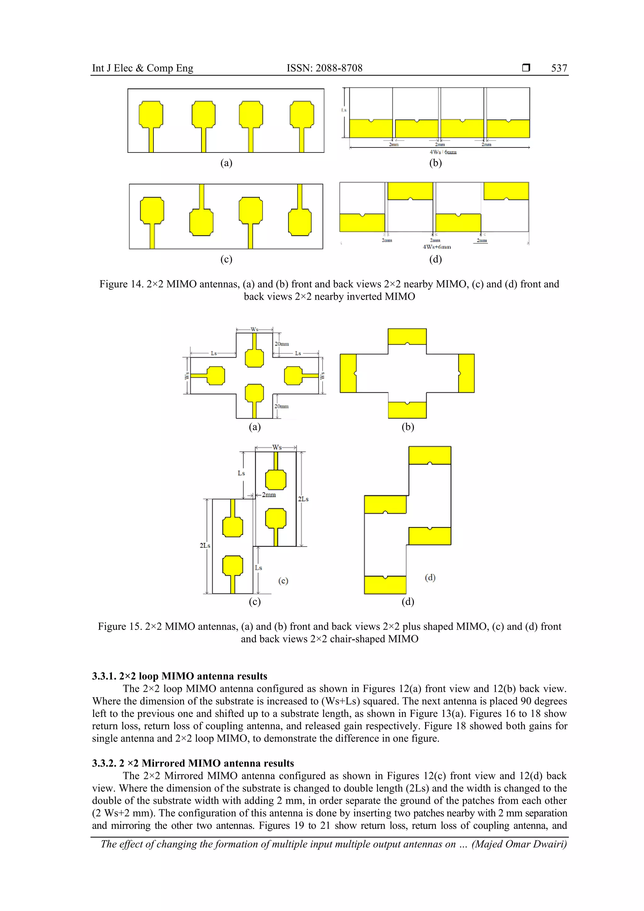
3.3.7. 2×2 plus-shaped MIMO antenna results
The proposed 2×2 plus-shaped MIMO antenna is configured as shown in Figures 15(a) front view
and 15(b) back view. The shape of this MIMO antenna is done like a plus-shape where the dimensions are
formed in a way that the width is twice the original substrate length plus the substrate width (2Ls+Ws), and
the length is the original substrate antenna width plus 40 mm (Ws+40 mm). Figures 36 to 38 shown return
loss, return loss of coupling antenna, and released gain respectively. From Figure 36 it is evident that S11 and
S22 are identical and that S33 and S44 are identical as well. Figure 38 shows both gains for a single antenna
and 2×2 nearby MIMO.
Figure 36. Return loss S11, S22, S33,
and S44 for 2×2 plus-shaped MIMO
Figure 37. Return loss coupling S12, S13, S14, S21,
S23, S24, S31, S32, S34, S41, S42, and S43 for 2×2
plus-shaped MIMO
Figure 38. Released gain single and 2×2 plus-shaped MIMO antenna
3.3.8. 2×2 chair-shaped MIMO antenna results
The 2×2 chair-shaped MIMO antenna is configured as shown in Figures 15(c) front view and 15(d)
back view. The shape of this MIMO antenna is done like a chair-shape where the dimensions are formed that
the width is twice the original substrate length plus 2 mm (2 Ws+2 mm), and the length is twice of the
original substrate (2Ls). Figures 39 to 41 show return loss, return loss of coupling antenna and released gain
respectively. From Figure 39 it is evident that S11 and S22 are identical and that S33 and S44 are identical as
well. Figure 41 shows both gains for a single antenna and 2×2 chair-shaped MIMO. Figure 42 shows a
Comparison between the released gain of 2×2 nearby and 2×2 nearby-inverted MIMO antenna.
2 3 4 5 6 7 8 9 10 11 12 13 14 15
-55
-50
-45
-40
-35
-30
-25
-20
-15
-10
-5
0
Return
loss
[dB]
Frequency [GHz]
S11
S22
S33
S44
2 3 4 5 6 7 8 9 10 11 12 13 14 15
-50
-45
-40
-35
-30
-25
-20
-15
-10
Return
loss
[dB]
Frequency [GHz]
S21
S31
S41
S12
S32
S42
S13
S23
S43
S14
S24
S34
2 3 4 5 6 7 8 9 10 11 12 13 14 15
0
1
2
3
4
5
6
7
Released
gain
[dB]
Frequency [GHz]
2×2 plus-shaped
single](https://image.slidesharecdn.com/v5426491emr30jul229nov21nn-221121064627-89bd6d4e/75/The-effect-of-changing-the-formation-of-multiple-input-multiple-output-antennas-on-the-gain-12-2048.jpg)
![Int J Elec & Comp Eng ISSN: 2088-8708
The effect of changing the formation of multiple input multiple output antennas on … (Majed Omar Dwairi)
543
Figure 39. Return loss S11, S22, S33, and S44 for
2×2 chair-shaped MIMO
Figure 40. Return loss coupling S12, S13, S14, S21,
S23, S24, S31, S32, S34, S41, S42, and S43 for 2×2
chair-shaped MIMO
Figure 41. Released gain single and 2×2 chair-
shaped MIMO antenna
Figure 42. Comparison released gain 2×2 plus-
shaped and 2×2 chair-shaped MIMO antenna
4. DISCUSSIONS OF THE RECEIVED RESULTS
The main purpose of this paper is to use the MIMO patch antenna to increase the released gain
without the need to increase the power radiated from the antenna. The investigation was done on three 2×1
MIMO antennas, and eight 2×2 MIMO antennas. The discussion will be as follows: first, comparison of the
original single antenna with all the MIMO antennas from the point of view of the operating UWB bandwidth;
then, comparison of the single antenna released gain with 2×1 MIMO antennas; comparison of original
antenna with 2×2 MIMO antennas; compare our results with other reported works, and finally, evaluation of
the best-released gain
4.1. UWB operating bandwidth
A composition between the original antenna and all other investigated MIMO antennas from the
point of view of the operating UWB bandwidth, resonant frequencies, and relative bandwidth, is listed in.
The operating bandwidth of the original single antenna ranges between 3.4-13.5 GHz; all the investigated
MIMO antennas are laying around this bandwidth. Most of the investigated MIMOs start before and end after
this bandwidth, and the relative bandwidth of all investigated antennas is around the relative bandwidth of the
original single antenna which is 119.5. Some of their values exceed the previously mentioned value, reaching
the maximum for the 2×1 inverted MIMO at about 169.6, whereas for the 2×2 nearby inverted MIMOs it
reaches 141.2. As seen form Table 2, 2×1 inverted MIMO gives the best UWB bandwidth with the best
relative gain, which gives a perspective to use this type of antenna for higher operating frequencies. In this
work, we are not investigating enhancement of the bandwidth, but this antenna could be studied separately
for this type of research.
2 3 4 5 6 7 8 9 10 11 12 13 14 15
-45
-40
-35
-30
-25
-20
-15
-10
-5
0
Return
loss
[dB]
Frequency [GHz]
S11
S22
S33
S44
2 3 4 5 6 7 8 9 10 11 12 13 14 15
-70
-65
-60
-55
-50
-45
-40
-35
-30
-25
-20
-15
-10
-5
Return
loss
[dB]
Frequency [GHz]
S21
S31
S41
S12
S32
S42
S13
S23
S43
S14
S24
S34
2 3 4 5 6 7 8 9 10 11 12 13 14 15
0
1
2
3
4
5
6
7
Released
gain
[dB]
Ferquency [GHz]
2×2 chair-shaped
single
2 3 4 5 6 7 8 9 10 11 12 13 14 15
1
2
3
4
5
6
7
Released
gain
[dB]
Frequency [GHz]
2×2 chair-shaped
2×2 plus-shaped](https://image.slidesharecdn.com/v5426491emr30jul229nov21nn-221121064627-89bd6d4e/75/The-effect-of-changing-the-formation-of-multiple-input-multiple-output-antennas-on-the-gain-13-2048.jpg)
![ ISSN: 2088-8708
Int J Elec & Comp Eng, Vol. 13, No. 1, February 2023: 531-548
544
Table 2. Comparison between a single antenna and all investigated antennas
Antenna Operating bandwidth GHz Resonant frequencies GHz Relative BW (%)
Single antenna 3.4-13.5 3.9, 6.77, 10.3 119.5
2×1 inverted MIMO 3.28-40 4.28, 6.7, 9.1, 12.6, 16.14, 24.4, 27.7,
32.6, 36.8, 40
169.6
2×1mirrored MIMO 3.5-12.67 3.9, 6, 6.6, 9.32, 10.6 113.4
2×1 nearby MIMO 3.18-14 3.67, 5.4, 6.82, 8.95, 10.1, 12.84 126
2×2 loop MIMO 3.48-12.5 4.07, 5.65, 6.5, 8.19, 9.6, 11.4 112.9
2×2 mirrored MIMO 3.12-13.68 3.8, 5.4, 6.7, 8.8, 9.85, 12.9 125.7
2×2 T-Mirrored MIMO S11 3.4-13.5 3.8, 6.8, 8.45, 10, 11, 13 119.5
S22 2.85-13.74 3.18, 5, 6.8, 9, 12.9 131.3
S33, S44 3.15-13.95 3.6, 5.75, 6.8, 9, 10, 12.96 126.3
2×2 T- mirrored center
inverted MIMO
S11 3.34-13.54 4.1, 6.16, 6.9, 10, 11,36, 13 120.8
S22 3.4-15 3.25, 5.35, 6.7, 9, 12.8,15 126.1
S33, S44 3.15-15 3.8, 4.7, 5.6,6.7, 9.15, 12.5,15 130.6
2×2 nearby MIMO S11, S22 2.88-13.95 3.2, 5, 7, 9, 9.76, 13.9 132
S33, S44 3.16-14.2 3.64, 5.15, 6.7, 9, 10, 12.83 127.2
2×2 nearby inverted
MIMO
S11, S22 3-15 3.34, 5.37, 6.7, 9, 12.8, 15 141.2
S33, S44 3.15-15 3.8, 5.6, 6.8, 9.12, 15 130.6
2×2 plus-shaped MIMO S11, S22 3.44-14.2 4.07, 6.04, 7, 10.2, 11.4, 122
S33, S44 3.35-12.66 4.06, 6.23, 9.7, 11.9 116.3
2×2 chair-shaped MIMO S11, S22 3.13-13.6 3.9, 5.64, 6.7, 9, 10.45, 12.14 125.2
S33, S44 3.36-13.5 3.9, 6.7,10.25, 12.9 120.3
4.2. Relative gain
Figure 43 shows the comparison between the original single antenna and 2×1 MIMO antennas,
where the worst case was received for mirrored MIMO. While the inverted MIMO gives the best results,
portions of bandwidth 8.82 to 10.1 GHz and 13.45 to 15 GHz received gain is less than the single antenna. In
Table 3, gain comparison for selected frequencies is listed.
From Table 3, it is evident that the maximum gain improvement is about 1.37 dB. Next, there is a
comparison between the single antenna and all 2×2 MIMO antennas as shown in Figure 44, to evaluate the
worst and the best-released gain received. A T-shaped MIMO antenna received the worst one as its gain was
equal or less than the single antenna except for portions of bandwidth 7.24 to 8.65 GHz, and 13.9 to 15 GHz,
where the maximum improvement in these portions was about 0.75 dB. The gain received for MIMO
antennas was better than a single antenna until 9.1, 9, 8.7, 9.67, 9.1, 9.22, and 8.9 GHz for plus-shaped,
chair-shaped, mirrored, nearby, nearby inverted, loop, and T-shaped inverted respectively. For the best
visualization of the received results of the improved gain comparison between all MIMO antennas and the
single antenna, the received gain for a selected frequency is listed in Table 4.
From Table 4, it is evident that the worst released gain improvement was received for T-shaped and
T-shaped inverted MIMO antennas followed by nearby inverted, mirrored, and nearby respectively. From
Table 4, it is notable that the best-released gain received was for plus-shaped, loop, and chair-shaped
respectively. The maximum gain improvement received was 3.07 dB at resonant frequency 8.2 GHz for
chair-shaped, whereas at this frequency 1.65 dB was received for both plus-shaped and loop antennas.
Figure 43. Comparison of the released gain between the single antenna and all 2×1 MIMO investigated
antennas
2 3 4 5 6 7 8 9 10 11 12 13 14 15
-1
0
1
2
3
4
5
6
7
8
Released
gain
[dB]
Frequency [GHz]
single
inverted
mirrored
nearby](https://image.slidesharecdn.com/v5426491emr30jul229nov21nn-221121064627-89bd6d4e/75/The-effect-of-changing-the-formation-of-multiple-input-multiple-output-antennas-on-the-gain-14-2048.jpg)
![Int J Elec & Comp Eng ISSN: 2088-8708
The effect of changing the formation of multiple input multiple output antennas on … (Majed Omar Dwairi)
545
Table 3. Gain comparison between single and 2×1 inverted MIMO antennas
Frequency [GHz] Single antenna [dB] 2×1 inverted MIMO antenna [dB] Gain improvement [dB]
3.4 2.63 4 +1.37
4.7 3.6 4.91 +1.31
6.2 2.32 3.47 +1.15
8 3.87 5.13 +1.26
8.82 4.10 4.10 0
9.2 4.61 3.71 -0.9
10.1 5.05 5.05 0
11.5 5.8 6.51 +0.71
13.45 5.5 5.5 0
The best gain for plus-shaped received was 2.73 dB at 4.2 GHz, whereas 1.17 and 0.92 dB were
received for loop and chair-shaped respectively. Finally, the best-released gain for loop received 2.4 dB at
3 and 3.85 GHz resonant frequencies at these frequencies plus-shaped received 1.24, 2.4 dB respectively;
however, chair-shaped received 0.38 and 0.25 dB respectively at these frequencies. The average
improvement received was 1.81, 1.45, and 1.27 dB for plus-shaped, loop, and chair-shaped respectively.
From the received simulation we conclude that the plus-shaped, loop and the chair-shaped MIMO
antennas give the best results of released gain. Depending on the purpose of using the antenna in terms of the
required narrowband frequencies within the UWB range and the purpose of this use, any of the antennas can
be used to increase the gain for narrow frequencies without the need to increase the radiated power.
Figure 44. Comparison the released gain between the single antenna and all 2×2 MIMO investigated
antennas
Table 4. The improved gain comparison between all MIMO antennas and the single antenna
Freq
GHz
Single
antenna
Plus-shaped Chair-
shaped
Mirrored Nearby Nearby
inverted
Loop T-shaped T-shaped
inverted
dB Imp. dB Imp. dB Imp. dB Imp. dB Imp. dB Imp. dB Imp. dB Imp.
3 2.27 3.55 1.28 3.14 0.87 2.62 0.35 3.54 1.27 2.27 0 4.67 2.4 2.64 0.37 1.72 -0.55
3.85 3.15 5.55 2.4 3.4 0.25 3.62 0.47 3.44 0.29 3.15 0 5.55 2.4 3.04 -0.11 3.15 0
4.2 3.43 6.16 2.73 4.35 0.92 4.42 0.99 4.42 0.99 4.42 0.99 4.6 1.17 3.3 -0.13 3.32 -0.11
4.5 3.54 5 1.46 5 1.46 4.47 0.93 4.83 1.29 4.75 1.21 4.35 0.81 3.54 0 3.83 0.29
5.2 3.6 4.51 0.91 5.7 2.1 4.85 1.25 4.7 1.1 4.7 1.1 4.82 1.22 3.6 0 4.04 0.44
6.2 2.35 5 2.65 3.53 1.18 4.63 2.28 6.04 3.69 4.83 2.48 3.85 1.5 2.35 0 3.95 1.6
6.8 3.4 6 2.6 4 1.6 4.23 0.83 4.23 0.83 4 1.6 4.66 1.26 3.57 0.17 4.94 1.54
8.2 3.55 5.20 1.65 6.62 3.07 4.8 1.25 5.5 1.95 4.87 1.32 5.20 1.65 4.22 0.67 4.86 1.31
9 4.35 4.92 0.57 4.35 0 4.08 -0.27 5.36 10.1 4.7 0.25 4.96 0.61 3.82 -0.53 4.3 -0.05
In Table 5, comparisons are made with other works to compare the received results. From Table 5, it
is evident that the proposed antennas are perspective, essentially 2×1 inverted MIMO as its bandwidth is the
largest without any mismatches in the whole interval; moreover, it could have more operating bandwidth than
shown (not simulated more than 40 GHz). The other three best 2×2 MIMO antennas give good peak gain
concerning the reported works, which seems to be good to use for UWB high gain without the need to
increase the radiated power.
2 3 4 5 6 7 8 9 10 11 12 13 14 15
0
1
2
3
4
5
6
7
Released
gain
[dB]
Frequency [GHz]
2×2 loop
2×2 Mirrored
2×2 T-Mirrored
2×2 T- mirrored center inverted
2×2 nearby
2×2 nearby inverted
2×2 plus-shaped
2×2 chair-shaped
Single](https://image.slidesharecdn.com/v5426491emr30jul229nov21nn-221121064627-89bd6d4e/75/The-effect-of-changing-the-formation-of-multiple-input-multiple-output-antennas-on-the-gain-15-2048.jpg)
![ ISSN: 2088-8708
Int J Elec & Comp Eng, Vol. 13, No. 1, February 2023: 531-548
546
Table 5. Comparison between the proposed MIMO antennas and recent works
Ref. Ant. Dimension
[mm]
MIMO Antenna Operating frequency
[GHz]
Peak gain [dB] for MIMO
Antenna
[12] 20 × 24 2×1 42.0 to 49.0 > 8
[18] 70 ×70 2×2 2 to 4.5 1.84-3.49
[27] 20×45 2×2 2.97 to 19.82 3.3-8.12
[28] 15×10.3 2×2 27 to 28.95 6.14
[29] 66 × 66 2×2 2.2 to 2.7 6.17
[30] 60 × 60 2×2 2.65 to 15 >6
This work Inverted 35×62 2×1 3.28 to 40 6.51
Plus-shaped 100×70 2×2 3.44 to 14.2 6.16
loop 65×65 2×2 2.48 to12.5 5.6
Chair-shaped 62×105 2×2 3.13 to 13.6 6.62
5. CONCLUSION
A different configuration of UWB 2×1 and 2×2 MIMIO micro strip patch antennas was proposed
and compared with the single UWB patch antenna to increase the released gain without the need to increase
the input power radiation, using different substrate dimensions and patch antenna placing. The best
simulation results of the three proposed 2×1 MIMO antenna received was for the 2×1 inverted with high
UWB and a bandwidth up to 40 GHz without any mismatches, in addition to a maximum gain up to 6.51 dB,
with an average gain of more than a single antenna of about 1.27 dB. For 2×2 MIMO antennas, the best
received gain compared with a single antenna gain were at 4.2 GHz about +2.73, +1.17, and +0.92 dB for
plus-shaped, loop, and chair-shaped respectively. The proposed MIMO antennas are suitable for narrowband
within the UWB such as WLAN, WiMAX, ARN, ITU-8, and X-Band without the need to increase the
radiated power of the transmitter antenna.
REFERENCES
[1] F. C. Commission, “Revision of Part 15 of the commission’s rules regarding ultra-wideband transmission systems,” First
Report and Order, FCC 02, V48, 2002.
[2] M. S. Soliman, M. O. Dwairi, I. I. M. A. Sulayman, and S. H. A. Almalki, “A comparative study for designing and modeling
patch antenna with different electromagnetic CAD approaches,” International Journal on Communications Antenna and
Propagation (IRECAP), vol. 6, no. 2, pp. 90–95, Apr. 2016, doi: 10.15866/irecap.v6i2.8718.
[3] M. O. Dwairi, M. S. Soliman, A. A. Alahmadi, S. H. A. Almalki, and I. I. M. Abu Sulayman, “Design and performance
analysis of fractal regular slotted-patch antennas for ultra-wideband communication systems,” Wireless Personal
Communications, vol. 105, no. 3, pp. 819–833, Apr. 2019, doi: 10.1007/s11277-019-06123-5.
[4] M. O. A.-D. Soliman, A. Y. Hendi, M. S. Soliman, and M. A. Nisirat, “Design of a compact ultra-wideband antenna for super-
wideband technology,” in 2019 13th European Conference on Antennas and Propagation (EuCAP), 2019, pp. 1–4.
[5] S. Alotaibi and A. A. Alotaibi, “Design of a planar tri-band Notch UWB antenna for X-band, WLAN, and WiMAX,”
Engineering, Technology & Applied Science Research, vol. 10, no. 6, pp. 6557–6562, Dec. 2020, doi: 10.48084/etasr.3904.
[6] M. O. Al-Dwairi, “A planar UWB semicircular-shaped monopole antenna with quadruple band notch for WiMAX, ARN,
WLAN, and X-Band,” International Journal of Electrical and Computer Engineering (IJECE), vol. 10, no. 1, pp. 908–918,
Feb. 2020, doi: 10.11591/ijece.v10i1.pp908-918.
[7] M. O. Al-Dwairi, A. Y. Hindi, M. S. Soliman, and M. F. Aljafari, “A compact UWB monopole antenna with penta band
notched characteristics,” TELKOMNIKA (Telecommunication Computing Electronics and Control), vol. 18, no. 2,
pp. 622–630, Apr. 2020, doi: 10.12928/telkomnika.v18i2.14542.
[8] N. M. Awad and M. K. Abdelazeez, “Multislot microstrip antenna for ultra-wide band applications,” Journal of King Saud
University - Engineering Sciences, vol. 30, no. 1, pp. 38–45, Jan. 2018, doi: 10.1016/j.jksues.2015.12.003.
[9] M. Rahman, W. T. Khan, and M. Imran, “Penta-notched UWB antenna with sharp frequency edge selectivity using
combination of SRR, CSRR, and DGS,” AEU - International Journal of Electronics and Communications, vol. 93,
pp. 116–122, Sep. 2018, doi: 10.1016/j.aeue.2018.06.010.
[10] M. Rahman and J.-D. Park, “The smallest form factor UWB antenna with quintuple rejection bands for IoT applications
utilizing RSRR and RCSRR,” Sensors, vol. 18, no. 3, Mar. 2018, doi: 10.3390/s18030911.
[11] R. B. G., C. Thampi, and S. K. Mohammed, “A CPW feed UWB antenna with quad band notches,” International Research
Journal of Engineering and Technology, vol. 5, no. 3, pp. 2048–2053, 2018.
[12] J.-T. Weng and Q.-X. Chu, “Wideband microstrip MIMO antenna for millimeter-wave applications,” in 2017 Sixth Asia-
Pacific Conference on Antennas and Propagation (APCAP), Oct. 2017, pp. 1–3, doi: 10.1109/APCAP.2017.8420888.
[13] M. Alibakhshikenari et al., “A comprehensive survey on ‘various decoupling mechanisms with focus on metamaterial and
metasurface principles applicable to SAR and MIMO antenna systems,’” IEEE Access, vol. 8, pp. 192965–193004, 2020, doi:
10.1109/ACCESS.2020.3032826.
[14] M. Alibakhshikenari, B. S. Virdee, and E. Limiti, “Study on isolation and radiation behaviours of a 34×34 array-antennas
based on SIW and metasurface properties for applications in terahertz band over 125–300 GHz,” Optik, vol. 206, Mar. 2020,
doi: 10.1016/j.ijleo.2019.163222.
[15] M. Alibakhshikenari et al., “Isolation enhancement of densely packed array antennas with periodic MTM-photonic bandgap
for SAR and MIMO systems,” IET Microwaves, Antennas & Propagation, vol. 14, no. 3, pp. 183–188, Mar. 2019, doi:
10.1049/iet-map.2018.5747.
[16] M. Alibakhshikenari, M. Khalily, B. S. Virdee, C. H. See, R. A. Abd-Alhameed, and E. Limiti, “Mutual-coupling isolation
using embedded metamaterial EM bandgap decoupling slab for densely packed array antennas,” IEEE Access, vol. 7,
pp. 51827–51840, 2019, doi: 10.1109/ACCESS.2019.2909950.](https://image.slidesharecdn.com/v5426491emr30jul229nov21nn-221121064627-89bd6d4e/75/The-effect-of-changing-the-formation-of-multiple-input-multiple-output-antennas-on-the-gain-16-2048.jpg)
![Int J Elec & Comp Eng ISSN: 2088-8708
The effect of changing the formation of multiple input multiple output antennas on … (Majed Omar Dwairi)
547
[17] M. Alibakhshikenari, M. Khalily, B. S. Virdee, C. H. See, R. A. Abd-Alhameed, and E. Limiti, “Mutual coupling suppression
between two closely placed microstrip patches using EM-bandgap metamaterial fractal loading,” IEEE Access, vol. 7,
pp. 23606–23614, 2019, doi: 10.1109/ACCESS.2019.2899326.
[18] B. Y. V. N. R. Swamy and P. Siddaiah, “Design of a compact 2×2 multi band MIMO antenna for wireless applications,”
International Journal of Recent Technology and Engineering (IJRTE), vol. 7, no. 6S2, pp. 674–683, 2019.
[19] H. Li, T. Wei, J. Ding, and C. Guo, “A dual-band polarized diversity microstrip MIMO antenna with high isolation for WLAN
application,” in 2016 11th International Symposium on Antennas, Propagation and EM Theory (ISAPE), Oct. 2016,
pp. 88–91, doi: 10.1109/ISAPE.2016.7833885.
[20] A. Khan, S. Geng, X. Zhao, Z. Shah, M. U. Jan, and M. A. Abdelbaky, “Design of MIMO antenna with an enhanced isolation
technique,” Electronics, vol. 9, no. 8, Jul. 2020, doi: 10.3390/electronics9081217.
[21] R. A. Sadeghzadeh, M. Alibakhshi-Kenari, and M. Naser-Moghadasi, “UWB antenna based on SCRLH-TLs for portable
wireless devices,” Microwave and Optical Technology Letters, vol. 58, no. 1, pp. 69–71, Jan. 2016, doi: 10.1002/mop.29491.
[22] M. Alibakhshi-Kenari, M. Naser-Moghadasi, R. Ali Sadeghzadeh, and B. Singh Virdee, “Metamaterial-based antennas for
integration in UWB transceivers and portable microwave handsets,” International Journal of RF and Microwave Computer-
Aided Engineering, vol. 26, no. 1, pp. 88–96, Jan. 2016, doi: 10.1002/mmce.20942.
[23] M. Alibakhshi‐Kenari, M. Naser‐Moghadasi, and R. A. Sadeghzadeh, “Composite right–left‐handed‐based antenna with wide
applications in very‐high frequency–ultra‐high frequency bands for radio transceivers,” IET Microwaves, Antennas &
Propagation, vol. 9, no. 15, pp. 1713–1726, Dec. 2015, doi: 10.1049/iet-map.2015.0308.
[24] M. Alibakhshi‐Kenari, M. Naser‐Moghadasi, and R. A. Sadeghzadeh, “Bandwidth and radiation specifications enhancement
of monopole antennas loaded with split ring resonators,” IET Microwaves, Antennas & Propagation, vol. 9, no. 14,
pp. 1487–1496, Nov. 2015, doi: 10.1049/iet-map.2015.0172.
[25] M. Alibakhshi-Kenari, M. Naser-Moghadasi, and R. Sadeghzadeh, “The resonating MTM-based miniaturized antennas for
wide-band RF-microwave systems,” Microwave and Optical Technology Letters, vol. 57, no. 10, pp. 2339–2344, Oct. 2015,
doi: 10.1002/mop.29328.
[26] Q. Wang, N. Mu, L. Wang, S. Safavi-Naeini, and J. Liu, “5G MIMO conformal microstrip antenna design,” Wireless
Communications and Mobile Computing, vol. 2017, pp. 1–11, 2017, doi: 10.1155/2017/7616825.
[27] H. Alsaif, “Extreme wide band MIMO antenna system for fifth generation wireless systems,” Engineering, Technology &
Applied Science Research, vol. 10, no. 2, pp. 5492–5495, Apr. 2020, doi: 10.48084/etasr.3413.
[28] R. K. Goyal and U. S. Modani, “Compact MIMO microstrip patch antenna design at 28 GHz for 5G smart phones,”
International Journal of Engineering Research & Technology (IJERT), vol. 9, no. 4, 2021, doi:
10.17577/IJERTCONV9IS04001.
[29] R. S. Bhadade and S. P. Mahajan, “High gain circularly polarized pentagonal microstrip for massive MIMO base station,”
Advanced Electromagnetics, vol. 8, no. 3, pp. 83–91, Sep. 2019, doi: 10.7716/aem.v8i3.764.
[30] M. O. Dwairi, “Increasing gain evaluation of 2×1 and 2×2 MIMO microstrip antennas,” Engineering, Technology & Applied
Science Research, vol. 11, no. 5, pp. 7531–7535, Oct. 2021, doi: 10.48084/etasr.4305.
BIOGRAPHIES OF AUTHORS
Majed Omar Dwairi is a PhD communication system, was born on the 10 of
December 1968 in Jordan. He received his diploma degree in 1994 and PhD degree from
Ukraine state Academy in 1998 in the field of multichannel communication. An associate
professor in the Department of Electrical Engineering, Faculty of Engineering Technology,
Al-Balqa Applied University Amman, Jordan. His research interests include optical
communication networks, digital communications, signal, and image processing, antenna
design, and microstrip patch antennas. He can be contacted at email: majeddw@bau.edu.jo.
Mohamed Salaheldeen Soliman An assistant professor in the Department of
Electrical Engineering, Faculty of Energy Engineering, Aswan University, Egypt. Currently,
he is with the Department of Electrical Engineering, Faculty of Engineering Taif University,
Saudi Arabia. Dr. Soliman had his Ph.D. in Communications Engineering from the Graduate
School of Engineering, Osaka University, Japan. He is the author and co-author of many
research journals and conference articles. He was granted many research projects from the
Deanship of Scientific Researches, Taif University, Saudi Arabia. His research interests
include wireless communications, phased and timed array signal processing, UWB microstrip
patch antennas, dielectric resonant antennas, numerical methods in electromagnetics, MIMO
antenna, optimization techniques in antenna design, and antenna measurement techniques. He
serves as a reviewer in many scientific journals (i.e PIER journals, International Journal of RF
and Microwave Computer-Aided Engineering) and TPC member in many international
conferences. Dr. Soliman is a senior member of IEEE-MTT/AP Society, KAUST chapter,
Saudi Arabia. He can be contacted at email: soliman.comm.tu.ksa@gmail.com.](https://image.slidesharecdn.com/v5426491emr30jul229nov21nn-221121064627-89bd6d4e/75/The-effect-of-changing-the-formation-of-multiple-input-multiple-output-antennas-on-the-gain-17-2048.jpg)

![International Journal of Electrical and Computer Engineering (IJECE)
Vol. 13, No. 1, February 2023, pp. 531~548
ISSN: 2088-8708, DOI: 10.11591/ijece.v13i1.pp531-548 531
Journal homepage: http://ijece.iaescore.com
The effect of changing the formation of multiple input multiple
output antennas on the gain
Majed Omar Dwairi1
, Mohamed Salaheldeen Soliman2,3
, Amjad Yousef Hendi1
, Ziad AL-Qadi1
1
Department of Electrical Engineering, Faculty of Engineering Technology Al-Balqa Applied University, Amman, Jordan
2
Department of Electrical Engineering Faculty of Energy Engineering, Aswan University, Aswan, Egypt
3
Department of Electrical Engineering, Faculty of Engineering, Taif University, Taif, Saudi Arabia
Article Info ABSTRACT
Article history:
Received Nov 9, 2021
Revised Jul 30, 2022
Accepted Aug 20, 2022
In this paper, different 2×1 and 2×2 multiple input multiple output (MIMO)
antennas were investigated with changing substrate shapes and changing the
placing of the patches on the substrate, all the investigated antennas based
on FR-4 substrate are characterized by 𝑝𝑒𝑟𝑚𝑖𝑡𝑡𝑖𝑣𝑖𝑡𝑦 = 4.4, and loss
𝑡𝑎𝑛𝑔𝑒𝑛𝑡 = 0.02, with a partial ground. The original antenna covered 3.4 to
13.5 GHz. The best simulation results of the proposed 2×1 MIMO antenna
received for 2×1 inverted with high ultra-wideband (UWB) with bandwidth
up to 40 GHz, the received maximum gain was up to 6.51 dB, with an
average gain of more than the original single antenna at about +1.27 dB. The
best of eight 2×2 MIMO antennas configurations that give good results were
shown. The best-received gain compared with a single antenna gain were at
4.2 GHz about +2.73, +1.17, and +0.92 dB for plus-shaped, loop, and
chair-shaped respectively. A comparison between the proposed MIMO
antennas and other reported works were done. The proposed MIMO
antennas give a good maximum gain and are suitable for different narrow
bands within the UWB such as wireless local area network (WLAN),
worldwide interoperability for microwave access (WiMAX), aeronautical
radio navigation (ARN), International Telecommunication Union 8-GHz
(ITU-8), and X-Band applications with the ability to give high gain without
the need to increase the radiated power of the transmitter antenna.
Keywords:
Multiple input multiple output
Released gain
Resonant frequency
Return loss
Ultra-wideband
This is an open access article under the CC BY-SA license.
Corresponding Author:
Majed Omar Dwairi
Department of Electrical Engineering, Faculty of Engineering Technology Al-Balqa Applied University
P.O. Box: 15008 Amman 11134, Jordan
Email: majeddw@bau.edu.jo
1. INTRODUCTION
Nowadays, ultra-wideband (UWB) micro strip antenna design plays an important role in modern
microwave antenna design; researchers give it more attention after UWB (3.1 to 10.6) GHz was licensed by
the Federal Communication Commission (FCC) [1]. The importance of using micro strip antenna is due to its
several advantages compared with other microwave antennas such as low profile, light weight, low cost,
capability of many frequency operations, and ease of integration with microwave integrated circuit. Many
simulation tools were introduced to microstrip antenna design such as: CST, HFSS, FEKO, IE3D, and others
that gave the researchers the possibility to work in this direction and obtain results close to the reality of the
antenna to be manufactured and adjust and improve it before manufacturing, to reach the required antenna
with accuracy and effectiveness. Some different parameters were investigated to determine the operated,
mismatched, and rejected bands such as those which were investigated Soliman et al. [2]. Moreover, to study
the effect of inserting different slots within the patch or ground or both of them, Dwairi et al. [3] proposed](https://crownmelresort.com/image.slidesharecdn.com/v5426491emr30jul229nov21nn-221121064627-89bd6d4e/75/The-effect-of-changing-the-formation-of-multiple-input-multiple-output-antennas-on-the-gain-1-2048.jpg)
![ ISSN: 2088-8708
Int J Elec & Comp Eng, Vol. 13, No. 1, February 2023: 531-548
532
twenty different fractal slots shaped on the patch studying the effect of these slots on the operating bandwidth
and decreasing the patch area, in addition, to studying the effect of their different fractal slots on the different
parameters. Soliman et al. [4] were investigated a compact UWB antenna using different ground slots to
enhance the operating bandwidth, the authors received bandwidth up to 31.1 GHz with a relative bandwidth
of about 164%. Alotaibi and Alotaibi [5] a triple-band notched filter was proposed using different slots
shaped were used U, T, and L-shaped slots used for worldwide interoperability for microwave access
(WiMAX), wireless local area network (WLAN), and X-Band used respectively to achieve the desired notch
filer. Al-Dwairi [6] proposed for filters with different slot configuration on the patch, feed, and the ground
receiving reject filters for WiMAX operating bandwidth 93.3-3.7GHz, aeronautical radio navigation (ARN)
operating bandwidth 4.2 to 4.5 GHz, WLAN operating bandwidth 5.15 to 5.825GHz, and X-Band (a segment
of the superhigh-frequency radio spectrum that lies between 5.2 GHz and 10.9 GHz and is used especially for
radars and for spacecraft communication, our investigating bandwidth 7.25 to 7.75). Al-Dwairi et al. [7]
proposed five band notched filters using U, S, and ∑-shaped on the patch, feed, and ground receiving
WiMAX, ARN, WLAN, X-Band, and the International Telecommunication Union 8-GHz (ITU-8). In
[8]–[11] the authors use different slots in the patch of the antenna or in its ground or on both, which were
inserted to eliminate unwanted narrow frequency bands within the operating UWB, known as filters,
receiving 3, 4, and 5 notched filters, such as in [10] received four rejection band filters using a very small
factor UWB microstrip antenna are proposed to be used in internet of things (IoT), and in mobile
communication, receiving five rejection bands for bandwidth from 3.5 to 8.2 GHz.
Multiple input multiple output (MIMO) antennas were introduced to micro strip antenna to improve
the data throughput, range, and gain for the received antenna without the need to increase the transmitted
power or its bandwidth, many works concentrated on this type of design such as Weng and Chu [12] were
choosing an optimized size and location of the slot on the feeding line receiving a high gain MIMO antenna
that is designed for mm-wave applications. The most challenging thing for MIMO antennas designer is the
mutual coupling effect that changes the input impedance of the individual antenna elements in an array and
therefore, changes the pattern of the antenna operation and degrades the performance of the array. Many
techniques and methods to reduce the mutual coupling depending on the application of the investigated
antennas and the way of excitation have been produced.
Alibakhshikenari et al. [13] produced a 2×2 MIMO antenna operating in three narrow bands from
2.11-4.42 GHz with reduced mutual coupling by implementing a proper slot on the partial ground and
increasing the efficiency up to 73% on the resonant frequencies. Alibakhshikenari et al. [14], [15] produced
different aperture-coupling and defected ground structures (DGS) to increase the insulation from the patch
and the feeding element; in [14] the aperture-coupling was used to isolate the micro strip by inserting
T-shaped and orthogonally around the squared patch, the produced antenna is applicable for WLAN
communication, while in [15] two circular patch antennas are closely placed to each other and inserted
H-shaped DGS on the ground that highly decreases the mutual coupling, producing MIMO antenna that
operates at 5.3 GHz frequency, which can be used for Wi-Fi and WiMAX. Microstrip antennas have various
applications for wireless communication systems using different microstrip antenna designs and
configurations for different applications.
Alibakhshikenari et al. [16] designed a 4-pair conformal micro strip MIMO antenna consisting of
eight cells each operating in ka-band (35 GHz), resulting in a reduction of the side lobe at the same time of
increasing the bandwidth; the simulated and measured results conformed. Alibakhshikenari et al. [17]
introduced a 5G handset mobile communication antenna using a compact 2×2 MIMO patch antenna that
characterizes by a super wideband starting from 2.97 to 19.82 GHz, this proposed antenna achieved a gain of
more than 8 dB. Swamy and Siddaiah [18], a 4-element MIMO patch antenna with inset line feeding was
investigated for narrowband from 27 to 28.95 GHz. The received results proved a reduction of BER at the
same time increasing the signal to noise ratio, and the resulting gain received was about 6.14 dB, with the
perspective to use this produced antenna for 5G mobile handset antenna application. Li et al. [19], a modified
pentagonal micro strip antenna was investigated and introduced a high gain of about 6.17 dB with a
perspective to be used for 5G applications. Khan et al. [20], the author shows that the gain improvement of
the proposed 2×2 MIMO antenna were from 1 to 2.5 dB, that has been achieved compared to the single patch
antenna. Alibakhshikenari et al. [21] proposed UWB antenna to exhibit excellent radiation characteristics,
using F and T-shaped slots on the ground and the arms respectively, receiving relative bandwidth of about
173% and a maximum gain 3.5 dBi.
Alibakhshikenari et al. [22] a very useful survey was presented with a comprehensive study of
deferent methods with different isolation based on meta surface inspired and metamaterial for antennas and
analyze each of the presented methods. In [23] reduced unwanted mutual coupling for 34 by 34 antenna array
by using substrate-integrated-waveguide (SIW) for operating at THz band, which is realized by interjecting
metallic via-holes between the radiating elements to block propagating surface waves. Alibakhshikenari et al.](https://crownmelresort.com/image.slidesharecdn.com/v5426491emr30jul229nov21nn-221121064627-89bd6d4e/75/The-effect-of-changing-the-formation-of-multiple-input-multiple-output-antennas-on-the-gain-2-2048.jpg)
![Int J Elec & Comp Eng ISSN: 2088-8708
The effect of changing the formation of multiple input multiple output antennas on … (Majed Omar Dwairi)
533
[24] used metamaterial photonic bandgap techniques to reduce mutual coupling which is simple and
effective. Alibakhshikenari et al. and Wang et al. [25], [26] an effective technique is used for suppressing the
mutual coupling based on a metamaterial (MTM) electromagnetic bandgap. Alsaif [27] a UWB microstrip
antenna has been proposed for portable wireless devices based on a simplified composite right/left-hand
transmission line, this antenna was implemented using F and T-shaped slots in the patch radiator, the
operating bandwidth operates from 0.6 to 9.2 GHz giving relative bandwidth of about 173.6% and gains
about 4 dBi. Proposed and investigated important antennas works based on metamaterials, for UWB portable
microwave devices and wireless communications [28]–[30].
In this paper, an UWB antenna based on [8], was optimized to operate at UWB, then the authors
inserted some slots within the patch and the feed line to reject WLAN and X-bands. The proposed antenna in
[8] is a good candidate for our investigation to be modified to MIMO scenarios with 2×1 and 2×2, with
different modifications to compare these MIMO antennas and discover which gives the best gain. The
remainder of this work has been organized as follows: section 2 single antenna design, next section 3
simulation results of 2×1 and 2×2 MIMO antennas; section 4 discussion of the received results. Finally,
conclusions and future work were discussed in section 5.
2. ANTENNA DESIGN
The investigated UWB micro strip patch antenna based on [8], is presented in Figures 1(a) to (c), the
substrate is built on FR4 with relative permittivity equal to 4.4 and loss tangent equal to 0.02. The antenna
dimensions are listed in Table 1. In order to improve the patch antenna bandwidth and its matching inserted
an arc cut of radius R mm at the corners of the rectangular patch antenna and the cutting polygonal slot in the
ground, which in turn neutralized the capacitive and inductive reactance receiving a pure resistive input
impedance [8]. The best slot cut circles at the rectangular angles are R1=R2=R3=R4=2 mm. The polygonal
dimensions are listed in Table 1. This produced antenna will be modified to different 2×1 and 2×2 MIMO
antennas and all the comparisons of the investigated MIMO antennas will be referred to this original antenna
in point of view return loss and the released gain.
Table 1. Antenna parameters
Length [mm] Width [mm] Height [mm]
Substrate Ls= 35 Ws =30 Hs =1.6
Patch antenna Lp =14.5 Wp =15 tp = 0.009
Feed line Lf = 13.5 Wf = 2.85
Ground Lg = 12.5 Wg =30
Ground slot polygonal shape with w = 3mm, L =0.75mm and L1= 1mm
(a) (b) (c)
Figure 1. The investigated antenna: (a) side view, (b) front view, and (c) back view
3. SIMULATION RESULTS
The simulation of the investigated single antenna and the all-proposed MIMOs antennas has been
carried out using CST-EM simulator 2018, where all the investigated antennas are based on the reference
antenna introduced in [8]. The investigation started with the simulation of the original antenna followed by
the three proposed 2×1 MIMO antennas designed and the results. Finally, an investigation of the eight
proposed 2×2 MIMO antennas designed and results.](https://crownmelresort.com/image.slidesharecdn.com/v5426491emr30jul229nov21nn-221121064627-89bd6d4e/75/The-effect-of-changing-the-formation-of-multiple-input-multiple-output-antennas-on-the-gain-3-2048.jpg)
![ ISSN: 2088-8708
Int J Elec & Comp Eng, Vol. 13, No. 1, February 2023: 531-548
534
3.1. Single antenna results
Equations should be placed at the center of the line and provided consecutively with equation
numbers. The investigated single antenna based on [8], shown in Figure 1. The simulation results of the
return loss (S11), voltage standing wave ratio (VSWR), and the released gain are shown in Figures 2 to 4.
The operating bandwidth for all proposed antennas has been from 2 to 15 GHz.
Figure 2. The simulated return loss for the single
antenna
Figure 3. The simulated VSWR for the single
antenna
Figure 4. The simulated released gain for the single antenna
3.2. 2×1 MIMO antenna results
Three different 2×1 antenna configuration was investigated based on changing the dimensions of the
substrate and the location of the patch antenna on the substrate. The investigated are shown in Figures 5(a) to
5(c), where the first 2×1 antenna was introduced as inverted MIMO, the second 2×1 was introduced as mirrored
MIMO, and finally, the third 2×1 antenna was introduced as nearby MIMO. For all the investigated 2×1 MIMO
antennas we found the return loss and the gain; which will be later compared in the discussion section.
3.2.1. 2×1 Inverted MIMO antenna
The proposed 2×1 inverted MIMO antenna is the modified single antenna substrate dimension
(2Ws+2mm×Ls×hs) mm3
, as shown in Figure 5(a). The two antennas are the same dimensions inverted
180 degrees with 2 mm inserted in the substrate width to separate the ground of the two antennas. The
simulation results of the return loss S11, S22, S12, and S21 (where S12, and S21 are the coupling return
loss), and the released gain are shown in Figures 6 and 7 respectively. In Figure 7, it is seen that S11 and S22
are identical and S12 and S21 are identical as well. From S-parameters, it is notable that the bandwidth is
received up to 40 GHz without any mismatched or rejected band; this is the only case that received these
results. From Figure 7, the overall released gain of the bandwidth is good.
2 3 4 5 6 7 8 9 10 11 12 13 14 15
-30
-25
-20
-15
-10
-5
0
S11[dB]
Frequency [GHz]
single ant.
2 3 4 5 6 7 8 9 10 11 12 13 14 15
1
2
3
4
5
6
7
8
9
10
11
12
13
14
15
VSWR
Ferquency [GHz]
VSWR single
2 3 4 5 6 7 8 9 10 11 12 13 14 15
0
1
2
3
4
5
6
7
Released
gain
[dB]
Frequency [GHz]
Max. gain over Ferquency](https://crownmelresort.com/image.slidesharecdn.com/v5426491emr30jul229nov21nn-221121064627-89bd6d4e/75/The-effect-of-changing-the-formation-of-multiple-input-multiple-output-antennas-on-the-gain-4-2048.jpg)
![Int J Elec & Comp Eng ISSN: 2088-8708
The effect of changing the formation of multiple input multiple output antennas on … (Majed Omar Dwairi)
535
(a) (b) (c)
Figure 5. 2×1 MIMO antennas, (a) inverted, (b) mirrored, and (c) nearby
Figure 6. The simulated return loss S11, S22, and
coupling S12, and S21 for 2×1 inverted MIMO
antenna
Figure 7. The simulated released gain for 2×1
inverted MIMO antenna
3.2.2. 2×1 mirrored MIMO antenna
The 2×1 mirrored MIMO antenna is shown in Figure 5(b), the modification is done by doubling the
substrate length, with the same width. The second patch antenna is the same dimensions but mirrors the first.
The simulation results of the return loss S11, S22, S12, and S21, and the released gain are shown in Figures 8
and 9, respectively.
Figure 8. the simulated return loss S11, S22, and
coupling S12, and S21 for 2×1 mirrored MIMO antenna
Figure 9. The simulated released gain for 2×1
mirrored MIMO antenna
2 4 6 8 10 12 14 16 18 20 22 24 26 28 30 32 34 36 38 40
-45
-40
-35
-30
-25
-20
-15
-10
-5
0
Return
loss
[dB]
Frequency [GHz]
S22
S12
S21
S11
2 4 6 8 10 12 14 16 18 20 22 24 26 28 30 32 34 36 38 40
0
1
2
3
4
5
6
7
8
Released
gain[dB]
Frequency [GHz]
Gain over Frequency
2 3 4 5 6 7 8 9 10 11 12 13 14 15
-35
-30
-25
-20
-15
-10
-5
0
Return
Loss
[dB]
Frequency [GHz]
S22
S12
S21
S11
2 4 6 8 10 12 14
0
1
2
3
4
5
Released
gain
[dB]
Frequency [GHz]
Max. gain over Frequency](https://crownmelresort.com/image.slidesharecdn.com/v5426491emr30jul229nov21nn-221121064627-89bd6d4e/75/The-effect-of-changing-the-formation-of-multiple-input-multiple-output-antennas-on-the-gain-5-2048.jpg)
![ ISSN: 2088-8708
Int J Elec & Comp Eng, Vol. 13, No. 1, February 2023: 531-548
536
3.2.3. 2×1 nearby MIMO antenna
The 2×1 nearby MIMO antenna is shown in Figure 5(c), the modification is done by doubling the
substrate width and adding 2mm to separate the ground of antennas, with the same antenna length. The
second patch antenna is the same dimensions nearby the first. The simulation results of the return loss S11,
S22, S12, and S21, and the released gain are shown in Figures 10 and 11 respectively.
Figure 10. The simulated return loss S11, S22, and
coupling S12, and S21 for 2×1 nearby MIMO antenna.
Figure 11. The simulated released gain for 2×1
nearby MIMO antenna
3.3. 2×2 MIMO antennas results
Eight 2×2 antenna configuration designs were a comparison will investigated with different antenna
location on the substrate as shown in Figures 12(a) to (d), Figures 13(a) to (d), Figures 14(a) to (d), and
Figures 15(a) to (d). The investigation was carried out for all MIMO antennas for return loss and released
gain that will be compared in the discussion section. A comparison will be carried out in the discussion
section.
(a) (b) (c) (d)
Figure 12. 2×2 MIMO antennas, (a) and (b) front and back views 2×2 loop MIMO, (c) and (d) front and back
views 2×2 mirrored MIMO
(a) (b) (c) (d)
Figure 13. 2×2 MIMO antennas, (a) and (b) front and back views 2×2 T-Mirrored MIMO, (c) and (d) front
and back views 2×2 T-mirrored center inverted MIMO
2 3 4 5 6 7 8 9 10 11 12 13 14 15
-25
-20
-15
-10
-5
0
Return
loss
[dB]
Frequency [GHz]
S11
S21
S12
S22
2 3 4 5 6 7 8 9 10 11 12 13 14 15
0
1
2
3
4
5
6
7
Released
gain[dB]
Frequency [GHz]
Max. gain over Frequency](https://crownmelresort.com/image.slidesharecdn.com/v5426491emr30jul229nov21nn-221121064627-89bd6d4e/75/The-effect-of-changing-the-formation-of-multiple-input-multiple-output-antennas-on-the-gain-6-2048.jpg)

![ ISSN: 2088-8708
Int J Elec & Comp Eng, Vol. 13, No. 1, February 2023: 531-548
538
released gain respectively. From Figure 19, it is evident that all the return losses are identical. Figure 21 showed
both gains for single antenna and 2×2 loop MIMO, to demonstrate the difference in one figure.
Figure 16. Return loss S11, S22, S33,
and S44 for 2×2 loop MIMO
Figure 17. Return loss coupling S12, S13, S14, S21,
S23, S24, S31, S32, S34, S41, S42, and S43 for 2×2
loop MIMO
Figure 18. Released gain single and 2×2 loop
MIMO antenna
Figure 19. Return loss S11, S22, S33, and S44 for
2×2 mirrored MIMO
Figure 20. Return loss coupling S12, S13, S14, S21,
S23, S24, S31, S32, S34, S41, S42, and S43 for 2×2
mirrored MIMO
Figure 21. Released gain single,
and 2×2 mirrored MIMO antenna
2 3 4 5 6 7 8 9 10 11 12 13 14 15
-60
-55
-50
-45
-40
-35
-30
-25
-20
-15
-10
-5
0
Return
loss
[dB]
Frequency [GHz]
S11
S22
S33
S44
2 3 4 5 6 7 8 9 10 11 12 13 14 15
-70
-65
-60
-55
-50
-45
-40
-35
-30
-25
-20
-15
-10
Return
loss
[dB]
Frequency [GHz]
S21
S31
S41
S12
S32
S42
S13
S23
S43
S14
S24
S34
2 3 4 5 6 7 8 9 10 11 12 13 14 15
0
1
2
3
4
5
6
7
Released
gain[dB]
Frequency [GHz]
single
2×2 loop
2 3 4 5 6 7 8 9 10 11 12 13 14 15
-25
-20
-15
-10
-5
0
Return
loss
[dB]
Frequency [GHz]
S11
S22
S33
S44
2 3 4 5 6 7 8 9 10 11 12 13 14 15
-50
-45
-40
-35
-30
-25
-20
-15
-10
Return
loss
[dB]
Frequency [GHz]
S21
S31
S41
S12
S32
S42
S13
S23
S43
S14
S24
S34
2 3 4 5 6 7 8 9 10 11 12 13 14 15
0
1
2
3
4
5
6
7
Releasd
gain[dB]
Frequency [GHz]
single
2×2 mirrored](https://crownmelresort.com/image.slidesharecdn.com/v5426491emr30jul229nov21nn-221121064627-89bd6d4e/75/The-effect-of-changing-the-formation-of-multiple-input-multiple-output-antennas-on-the-gain-8-2048.jpg)
![Int J Elec & Comp Eng ISSN: 2088-8708
The effect of changing the formation of multiple input multiple output antennas on … (Majed Omar Dwairi)
539
3.3.3. 2×2 T-Mirrored MIMO antenna results
The 2×2 T-Mirrored MIMO antenna is configured as shown in Figures 13(a) front view and 13(b)
back view. The shape of this MIMO antenna is T-shaped, where the dimension of the substrate is changed to
double length (2Ls) and the width is changed to the triple of the substrate width with adding 4 mm
(3 Ws+4 mm). The upper antennas are in the same direction but are mirroring the base antenna. Figures 22 to
24 show return loss, return loss of coupling antenna and released gain respectively. From Figure 22 it is
evident that S22 and S33 are identical, whereas S11 and S44 are different. Figure 23 showed both gains for a
single antenna and 2×2 T-shaped MIMO.
2 3 4 5 6 7 8 9 10 11 12 13 14 15
-50
-45
-40
-35
-30
-25
-20
-15
-10
Return
loss
[dB]
Frequency [GHz]
S21
S31
S41
S12
S32
S42
S13
S23
S43
S14
S24
S34
Figure 22. Return loss S11, S22, S33, and S44 for
2×2 T-mirrored MIMO
Figure 23. Return loss coupling S12, S13, S14, S21,
S23, S24, S31, S32, S34, S41, S42, and S43 for 2×2
T-mirrored MIMO
Figure 24. Released gain single, and 2×2 T-mirrored MIMO antenna
3.3.4. 2×2 T-Mirrored center inverted MIMO antenna results
The proposed simulation 2×2 T-Mirrored center inverted MIMO antenna is configured as shown in
Figures 13(c) front view and 13(d) back view. The shape and dimensions of this MIMO antenna is the same
as T-mirrored Figures 13(a) and 13(b), with one difference where outer upper antennas are in the same
direction as the lower base antenna. Figures 25 to 27 show return loss, return loss of coupling antenna and
released gain respectively. From Figure 25 it is evident that S33 and S44 are identical, whereas S11 and S22
are different. Figure 27 shows both gains for a single antenna and 2×2 T-shaped MIMO. In Figure 28 a
comparison of released gain was made between T-shaped and this antenna; as evident, this T-mirrored center
inverted MIMO antenna configuration gives better gain over the operating UWB.
3.3.5. 2×2 nearby MIMO antenna results
The 2×2 nearby MIMO antenna is configured as shown in Figures 14(a) front view and 14(b) back
view. The shape and dimensions of this MIMO antenna is done by increasing the width of the substrate four
2 3 4 5 6 7 8 9 10 11 12 13 14 15
-35
-30
-25
-20
-15
-10
-5
0
Return
loss
[dB]
Frequency [GHz]
S11
S22
S33
S44
2 3 4 5 6 7 8 9 10 11 12 13 14 15
0
1
2
3
4
5
6
7
Released
gain[dB]
Frequency [GHz]
2×2 T-Mirrored
single](https://crownmelresort.com/image.slidesharecdn.com/v5426491emr30jul229nov21nn-221121064627-89bd6d4e/75/The-effect-of-changing-the-formation-of-multiple-input-multiple-output-antennas-on-the-gain-9-2048.jpg)
![ ISSN: 2088-8708
Int J Elec & Comp Eng, Vol. 13, No. 1, February 2023: 531-548
540
times with adding 2 mm spacing between neighboring antennas (4 Ws+6 mm), with the same substrate length
(Ls). Figures 29 to 31 show return loss, return loss of coupling antenna and released gain respectively. From
Figure 29 it is evident that S11 and S22 are identical, and that S33 and S44 are identical as well. Figure 30
shows both gains for a single antenna and 2×2 nearby MIMO.
2 3 4 5 6 7 8 9 10 11 12 13 14 15
-40
-35
-30
-25
-20
-15
-10
Return
loss
[dB]
Frequency [GHz]
S21
S31
S41
S12
S32
S42
S13
S23
S43
S14
S24
S34
Figure 25. Return loss S11, S22, S33, and S44 for
2×2 T-mirrored center inverted MIMO
Figure 26. Return loss coupling S12, S13, S14, S21,
S23, S24, S31, S32, S34, S41, S42, and S43 for 2×2
T-mirrored center inverted MIMO
Figure 27. Released gain single and 2×2 mirrored center inverted MIMO antenna
Figure 28. Comparison released gain 2×2 T-mirrored
and 2×2 T-mirrored center inverted MIMO antenna
Figure 29. Return loss S11, S22, S33, and S44 for
2×2 nearby MIMO
2 3 4 5 6 7 8 9 10 11 12 13 14 15
-40
-30
-20
-10
0
Return
loss
[dB]
Frequency [GHz]
S11
S22
S33
S44
2 3 4 5 6 7 8 9 10 11 12 13 14 15
1
2
3
4
5
6
7
Released
gain
[dB]
Frequency [GHz]
2×2 T-center invert
single
2 3 4 5 6 7 8 9 10 11 12 13 14 15
1
2
3
4
5
6
Released
gain
[dB]
Frequency [GHz]
2×2 T-mirrored center inverted
2×2 T-mirrored
2 3 4 5 6 7 8 9 10 11 12 13 14 15
-25
-20
-15
-10
-5
0
Return
loss
[dB]
Frequency [GHz]
S11
S22
S33
S44](https://crownmelresort.com/image.slidesharecdn.com/v5426491emr30jul229nov21nn-221121064627-89bd6d4e/75/The-effect-of-changing-the-formation-of-multiple-input-multiple-output-antennas-on-the-gain-10-2048.jpg)
![Int J Elec & Comp Eng ISSN: 2088-8708
The effect of changing the formation of multiple input multiple output antennas on … (Majed Omar Dwairi)
541
2 3 4 5 6 7 8 9 10 11 12 13 14 15
-50
-40
-30
-20
-10
Return
loss
[dB]
Frequency [GHz]
S21
S31
S41
S12
S32
S42
S13
S23
S43
S14
S24
S34
Figure 30. Return loss coupling S12, S13, S14, S21,
S23, S24, S31, S32, S34, S41, S42, and S43 for 2×2
nearby MIMO
Figure 31. Released gain single, and 2×2 nearby
MIMO antenna
3.3.6. 2×2 nearby-inverted MIMO antenna results
The proposed 2×2 nearby inverted MIMO antenna is configured as shown in Figures 14(c) front
view and 14(d) back view. The shape and dimensions of this MIMO antenna are the same as 2×2 nearby
MIMO antenna except that every antenna is an inverted version of the nearby one. Figures 32 to 34 show
return loss, return loss of coupling antenna and released gain respectively. From Figure 32 it is evident that
S11 and S22 are identical, and that S33 and S44 are identical as well. Figure 35 shows a comparison between
the released gain of 2×2 nearby and 2×2 nearby-inverted MIMO antenna.
2 3 4 5 6 7 8 9 10 11 12 13 14 15
-40
-35
-30
-25
-20
-15
-10
Return
loss
[dB]
Frequency [GHz]
S21
S31
S41
S12
S32
S42
S13
S23
S43
S14
S24
S34
Figure 32. Return loss S11, S22, S33,
and S44 for 2×2 nearby inverted MIMO
Figure 33. Return loss coupling S12, S13, S14, S21,
S23, S24, S31, S32, S34, S41, S42, and S43 for 2×2
nearby inverted MIMO
Figure 34. Released gain single and 2×2 nearby
inverted MIMO antenna
Figure 35. Comparison released gain 2×2 nearby and
2×2 nearby-inverted MIMO antenna
2 3 4 5 6 7 8 9 10 11 12 13 14 15
-1
0
1
2
3
4
5
6
7
Released
gain[dB]
Frequency [GHz]
single
2×2 nearby
2 3 4 5 6 7 8 9 10 11 12 13 14 15
-30
-25
-20
-15
-10
-5
0
Retuirn
loss
[dB]
Frequency [GHz]
S11
S22
S33
S44
2 3 4 5 6 7 8 9 10 11 12 13 14 15
0
1
2
3
4
5
6
7
Released
gain
[dB]
Frequency [GHz]
2×2 nearby-inverted
single
2 3 4 5 6 7 8 9 10 11 12 13 14 15
1
2
3
4
5
6
7
Released
gain
[dB]
Frequency [GHz]
2×2 nearby
2×2 nearby-inverted](https://crownmelresort.com/image.slidesharecdn.com/v5426491emr30jul229nov21nn-221121064627-89bd6d4e/75/The-effect-of-changing-the-formation-of-multiple-input-multiple-output-antennas-on-the-gain-11-2048.jpg)
![ ISSN: 2088-8708
Int J Elec & Comp Eng, Vol. 13, No. 1, February 2023: 531-548
542
3.3.7. 2×2 plus-shaped MIMO antenna results
The proposed 2×2 plus-shaped MIMO antenna is configured as shown in Figures 15(a) front view
and 15(b) back view. The shape of this MIMO antenna is done like a plus-shape where the dimensions are
formed in a way that the width is twice the original substrate length plus the substrate width (2Ls+Ws), and
the length is the original substrate antenna width plus 40 mm (Ws+40 mm). Figures 36 to 38 shown return
loss, return loss of coupling antenna, and released gain respectively. From Figure 36 it is evident that S11 and
S22 are identical and that S33 and S44 are identical as well. Figure 38 shows both gains for a single antenna
and 2×2 nearby MIMO.
Figure 36. Return loss S11, S22, S33,
and S44 for 2×2 plus-shaped MIMO
Figure 37. Return loss coupling S12, S13, S14, S21,
S23, S24, S31, S32, S34, S41, S42, and S43 for 2×2
plus-shaped MIMO
Figure 38. Released gain single and 2×2 plus-shaped MIMO antenna
3.3.8. 2×2 chair-shaped MIMO antenna results
The 2×2 chair-shaped MIMO antenna is configured as shown in Figures 15(c) front view and 15(d)
back view. The shape of this MIMO antenna is done like a chair-shape where the dimensions are formed that
the width is twice the original substrate length plus 2 mm (2 Ws+2 mm), and the length is twice of the
original substrate (2Ls). Figures 39 to 41 show return loss, return loss of coupling antenna and released gain
respectively. From Figure 39 it is evident that S11 and S22 are identical and that S33 and S44 are identical as
well. Figure 41 shows both gains for a single antenna and 2×2 chair-shaped MIMO. Figure 42 shows a
Comparison between the released gain of 2×2 nearby and 2×2 nearby-inverted MIMO antenna.
2 3 4 5 6 7 8 9 10 11 12 13 14 15
-55
-50
-45
-40
-35
-30
-25
-20
-15
-10
-5
0
Return
loss
[dB]
Frequency [GHz]
S11
S22
S33
S44
2 3 4 5 6 7 8 9 10 11 12 13 14 15
-50
-45
-40
-35
-30
-25
-20
-15
-10
Return
loss
[dB]
Frequency [GHz]
S21
S31
S41
S12
S32
S42
S13
S23
S43
S14
S24
S34
2 3 4 5 6 7 8 9 10 11 12 13 14 15
0
1
2
3
4
5
6
7
Released
gain
[dB]
Frequency [GHz]
2×2 plus-shaped
single](https://crownmelresort.com/image.slidesharecdn.com/v5426491emr30jul229nov21nn-221121064627-89bd6d4e/75/The-effect-of-changing-the-formation-of-multiple-input-multiple-output-antennas-on-the-gain-12-2048.jpg)
![Int J Elec & Comp Eng ISSN: 2088-8708
The effect of changing the formation of multiple input multiple output antennas on … (Majed Omar Dwairi)
543
Figure 39. Return loss S11, S22, S33, and S44 for
2×2 chair-shaped MIMO
Figure 40. Return loss coupling S12, S13, S14, S21,
S23, S24, S31, S32, S34, S41, S42, and S43 for 2×2
chair-shaped MIMO
Figure 41. Released gain single and 2×2 chair-
shaped MIMO antenna
Figure 42. Comparison released gain 2×2 plus-
shaped and 2×2 chair-shaped MIMO antenna
4. DISCUSSIONS OF THE RECEIVED RESULTS
The main purpose of this paper is to use the MIMO patch antenna to increase the released gain
without the need to increase the power radiated from the antenna. The investigation was done on three 2×1
MIMO antennas, and eight 2×2 MIMO antennas. The discussion will be as follows: first, comparison of the
original single antenna with all the MIMO antennas from the point of view of the operating UWB bandwidth;
then, comparison of the single antenna released gain with 2×1 MIMO antennas; comparison of original
antenna with 2×2 MIMO antennas; compare our results with other reported works, and finally, evaluation of
the best-released gain
4.1. UWB operating bandwidth
A composition between the original antenna and all other investigated MIMO antennas from the
point of view of the operating UWB bandwidth, resonant frequencies, and relative bandwidth, is listed in.
The operating bandwidth of the original single antenna ranges between 3.4-13.5 GHz; all the investigated
MIMO antennas are laying around this bandwidth. Most of the investigated MIMOs start before and end after
this bandwidth, and the relative bandwidth of all investigated antennas is around the relative bandwidth of the
original single antenna which is 119.5. Some of their values exceed the previously mentioned value, reaching
the maximum for the 2×1 inverted MIMO at about 169.6, whereas for the 2×2 nearby inverted MIMOs it
reaches 141.2. As seen form Table 2, 2×1 inverted MIMO gives the best UWB bandwidth with the best
relative gain, which gives a perspective to use this type of antenna for higher operating frequencies. In this
work, we are not investigating enhancement of the bandwidth, but this antenna could be studied separately
for this type of research.
2 3 4 5 6 7 8 9 10 11 12 13 14 15
-45
-40
-35
-30
-25
-20
-15
-10
-5
0
Return
loss
[dB]
Frequency [GHz]
S11
S22
S33
S44
2 3 4 5 6 7 8 9 10 11 12 13 14 15
-70
-65
-60
-55
-50
-45
-40
-35
-30
-25
-20
-15
-10
-5
Return
loss
[dB]
Frequency [GHz]
S21
S31
S41
S12
S32
S42
S13
S23
S43
S14
S24
S34
2 3 4 5 6 7 8 9 10 11 12 13 14 15
0
1
2
3
4
5
6
7
Released
gain
[dB]
Ferquency [GHz]
2×2 chair-shaped
single
2 3 4 5 6 7 8 9 10 11 12 13 14 15
1
2
3
4
5
6
7
Released
gain
[dB]
Frequency [GHz]
2×2 chair-shaped
2×2 plus-shaped](https://crownmelresort.com/image.slidesharecdn.com/v5426491emr30jul229nov21nn-221121064627-89bd6d4e/75/The-effect-of-changing-the-formation-of-multiple-input-multiple-output-antennas-on-the-gain-13-2048.jpg)
![ ISSN: 2088-8708
Int J Elec & Comp Eng, Vol. 13, No. 1, February 2023: 531-548
544
Table 2. Comparison between a single antenna and all investigated antennas
Antenna Operating bandwidth GHz Resonant frequencies GHz Relative BW (%)
Single antenna 3.4-13.5 3.9, 6.77, 10.3 119.5
2×1 inverted MIMO 3.28-40 4.28, 6.7, 9.1, 12.6, 16.14, 24.4, 27.7,
32.6, 36.8, 40
169.6
2×1mirrored MIMO 3.5-12.67 3.9, 6, 6.6, 9.32, 10.6 113.4
2×1 nearby MIMO 3.18-14 3.67, 5.4, 6.82, 8.95, 10.1, 12.84 126
2×2 loop MIMO 3.48-12.5 4.07, 5.65, 6.5, 8.19, 9.6, 11.4 112.9
2×2 mirrored MIMO 3.12-13.68 3.8, 5.4, 6.7, 8.8, 9.85, 12.9 125.7
2×2 T-Mirrored MIMO S11 3.4-13.5 3.8, 6.8, 8.45, 10, 11, 13 119.5
S22 2.85-13.74 3.18, 5, 6.8, 9, 12.9 131.3
S33, S44 3.15-13.95 3.6, 5.75, 6.8, 9, 10, 12.96 126.3
2×2 T- mirrored center
inverted MIMO
S11 3.34-13.54 4.1, 6.16, 6.9, 10, 11,36, 13 120.8
S22 3.4-15 3.25, 5.35, 6.7, 9, 12.8,15 126.1
S33, S44 3.15-15 3.8, 4.7, 5.6,6.7, 9.15, 12.5,15 130.6
2×2 nearby MIMO S11, S22 2.88-13.95 3.2, 5, 7, 9, 9.76, 13.9 132
S33, S44 3.16-14.2 3.64, 5.15, 6.7, 9, 10, 12.83 127.2
2×2 nearby inverted
MIMO
S11, S22 3-15 3.34, 5.37, 6.7, 9, 12.8, 15 141.2
S33, S44 3.15-15 3.8, 5.6, 6.8, 9.12, 15 130.6
2×2 plus-shaped MIMO S11, S22 3.44-14.2 4.07, 6.04, 7, 10.2, 11.4, 122
S33, S44 3.35-12.66 4.06, 6.23, 9.7, 11.9 116.3
2×2 chair-shaped MIMO S11, S22 3.13-13.6 3.9, 5.64, 6.7, 9, 10.45, 12.14 125.2
S33, S44 3.36-13.5 3.9, 6.7,10.25, 12.9 120.3
4.2. Relative gain
Figure 43 shows the comparison between the original single antenna and 2×1 MIMO antennas,
where the worst case was received for mirrored MIMO. While the inverted MIMO gives the best results,
portions of bandwidth 8.82 to 10.1 GHz and 13.45 to 15 GHz received gain is less than the single antenna. In
Table 3, gain comparison for selected frequencies is listed.
From Table 3, it is evident that the maximum gain improvement is about 1.37 dB. Next, there is a
comparison between the single antenna and all 2×2 MIMO antennas as shown in Figure 44, to evaluate the
worst and the best-released gain received. A T-shaped MIMO antenna received the worst one as its gain was
equal or less than the single antenna except for portions of bandwidth 7.24 to 8.65 GHz, and 13.9 to 15 GHz,
where the maximum improvement in these portions was about 0.75 dB. The gain received for MIMO
antennas was better than a single antenna until 9.1, 9, 8.7, 9.67, 9.1, 9.22, and 8.9 GHz for plus-shaped,
chair-shaped, mirrored, nearby, nearby inverted, loop, and T-shaped inverted respectively. For the best
visualization of the received results of the improved gain comparison between all MIMO antennas and the
single antenna, the received gain for a selected frequency is listed in Table 4.
From Table 4, it is evident that the worst released gain improvement was received for T-shaped and
T-shaped inverted MIMO antennas followed by nearby inverted, mirrored, and nearby respectively. From
Table 4, it is notable that the best-released gain received was for plus-shaped, loop, and chair-shaped
respectively. The maximum gain improvement received was 3.07 dB at resonant frequency 8.2 GHz for
chair-shaped, whereas at this frequency 1.65 dB was received for both plus-shaped and loop antennas.
Figure 43. Comparison of the released gain between the single antenna and all 2×1 MIMO investigated
antennas
2 3 4 5 6 7 8 9 10 11 12 13 14 15
-1
0
1
2
3
4
5
6
7
8
Released
gain
[dB]
Frequency [GHz]
single
inverted
mirrored
nearby](https://crownmelresort.com/image.slidesharecdn.com/v5426491emr30jul229nov21nn-221121064627-89bd6d4e/75/The-effect-of-changing-the-formation-of-multiple-input-multiple-output-antennas-on-the-gain-14-2048.jpg)
![Int J Elec & Comp Eng ISSN: 2088-8708
The effect of changing the formation of multiple input multiple output antennas on … (Majed Omar Dwairi)
545
Table 3. Gain comparison between single and 2×1 inverted MIMO antennas
Frequency [GHz] Single antenna [dB] 2×1 inverted MIMO antenna [dB] Gain improvement [dB]
3.4 2.63 4 +1.37
4.7 3.6 4.91 +1.31
6.2 2.32 3.47 +1.15
8 3.87 5.13 +1.26
8.82 4.10 4.10 0
9.2 4.61 3.71 -0.9
10.1 5.05 5.05 0
11.5 5.8 6.51 +0.71
13.45 5.5 5.5 0
The best gain for plus-shaped received was 2.73 dB at 4.2 GHz, whereas 1.17 and 0.92 dB were
received for loop and chair-shaped respectively. Finally, the best-released gain for loop received 2.4 dB at
3 and 3.85 GHz resonant frequencies at these frequencies plus-shaped received 1.24, 2.4 dB respectively;
however, chair-shaped received 0.38 and 0.25 dB respectively at these frequencies. The average
improvement received was 1.81, 1.45, and 1.27 dB for plus-shaped, loop, and chair-shaped respectively.
From the received simulation we conclude that the plus-shaped, loop and the chair-shaped MIMO
antennas give the best results of released gain. Depending on the purpose of using the antenna in terms of the
required narrowband frequencies within the UWB range and the purpose of this use, any of the antennas can
be used to increase the gain for narrow frequencies without the need to increase the radiated power.
Figure 44. Comparison the released gain between the single antenna and all 2×2 MIMO investigated
antennas
Table 4. The improved gain comparison between all MIMO antennas and the single antenna
Freq
GHz
Single
antenna
Plus-shaped Chair-
shaped
Mirrored Nearby Nearby
inverted
Loop T-shaped T-shaped
inverted
dB Imp. dB Imp. dB Imp. dB Imp. dB Imp. dB Imp. dB Imp. dB Imp.
3 2.27 3.55 1.28 3.14 0.87 2.62 0.35 3.54 1.27 2.27 0 4.67 2.4 2.64 0.37 1.72 -0.55
3.85 3.15 5.55 2.4 3.4 0.25 3.62 0.47 3.44 0.29 3.15 0 5.55 2.4 3.04 -0.11 3.15 0
4.2 3.43 6.16 2.73 4.35 0.92 4.42 0.99 4.42 0.99 4.42 0.99 4.6 1.17 3.3 -0.13 3.32 -0.11
4.5 3.54 5 1.46 5 1.46 4.47 0.93 4.83 1.29 4.75 1.21 4.35 0.81 3.54 0 3.83 0.29
5.2 3.6 4.51 0.91 5.7 2.1 4.85 1.25 4.7 1.1 4.7 1.1 4.82 1.22 3.6 0 4.04 0.44
6.2 2.35 5 2.65 3.53 1.18 4.63 2.28 6.04 3.69 4.83 2.48 3.85 1.5 2.35 0 3.95 1.6
6.8 3.4 6 2.6 4 1.6 4.23 0.83 4.23 0.83 4 1.6 4.66 1.26 3.57 0.17 4.94 1.54
8.2 3.55 5.20 1.65 6.62 3.07 4.8 1.25 5.5 1.95 4.87 1.32 5.20 1.65 4.22 0.67 4.86 1.31
9 4.35 4.92 0.57 4.35 0 4.08 -0.27 5.36 10.1 4.7 0.25 4.96 0.61 3.82 -0.53 4.3 -0.05
In Table 5, comparisons are made with other works to compare the received results. From Table 5, it
is evident that the proposed antennas are perspective, essentially 2×1 inverted MIMO as its bandwidth is the
largest without any mismatches in the whole interval; moreover, it could have more operating bandwidth than
shown (not simulated more than 40 GHz). The other three best 2×2 MIMO antennas give good peak gain
concerning the reported works, which seems to be good to use for UWB high gain without the need to
increase the radiated power.
2 3 4 5 6 7 8 9 10 11 12 13 14 15
0
1
2
3
4
5
6
7
Released
gain
[dB]
Frequency [GHz]
2×2 loop
2×2 Mirrored
2×2 T-Mirrored
2×2 T- mirrored center inverted
2×2 nearby
2×2 nearby inverted
2×2 plus-shaped
2×2 chair-shaped
Single](https://crownmelresort.com/image.slidesharecdn.com/v5426491emr30jul229nov21nn-221121064627-89bd6d4e/75/The-effect-of-changing-the-formation-of-multiple-input-multiple-output-antennas-on-the-gain-15-2048.jpg)
![ ISSN: 2088-8708
Int J Elec & Comp Eng, Vol. 13, No. 1, February 2023: 531-548
546
Table 5. Comparison between the proposed MIMO antennas and recent works
Ref. Ant. Dimension
[mm]
MIMO Antenna Operating frequency
[GHz]
Peak gain [dB] for MIMO
Antenna
[12] 20 × 24 2×1 42.0 to 49.0 > 8
[18] 70 ×70 2×2 2 to 4.5 1.84-3.49
[27] 20×45 2×2 2.97 to 19.82 3.3-8.12
[28] 15×10.3 2×2 27 to 28.95 6.14
[29] 66 × 66 2×2 2.2 to 2.7 6.17
[30] 60 × 60 2×2 2.65 to 15 >6
This work Inverted 35×62 2×1 3.28 to 40 6.51
Plus-shaped 100×70 2×2 3.44 to 14.2 6.16
loop 65×65 2×2 2.48 to12.5 5.6
Chair-shaped 62×105 2×2 3.13 to 13.6 6.62
5. CONCLUSION
A different configuration of UWB 2×1 and 2×2 MIMIO micro strip patch antennas was proposed
and compared with the single UWB patch antenna to increase the released gain without the need to increase
the input power radiation, using different substrate dimensions and patch antenna placing. The best
simulation results of the three proposed 2×1 MIMO antenna received was for the 2×1 inverted with high
UWB and a bandwidth up to 40 GHz without any mismatches, in addition to a maximum gain up to 6.51 dB,
with an average gain of more than a single antenna of about 1.27 dB. For 2×2 MIMO antennas, the best
received gain compared with a single antenna gain were at 4.2 GHz about +2.73, +1.17, and +0.92 dB for
plus-shaped, loop, and chair-shaped respectively. The proposed MIMO antennas are suitable for narrowband
within the UWB such as WLAN, WiMAX, ARN, ITU-8, and X-Band without the need to increase the
radiated power of the transmitter antenna.
REFERENCES
[1] F. C. Commission, “Revision of Part 15 of the commission’s rules regarding ultra-wideband transmission systems,” First
Report and Order, FCC 02, V48, 2002.
[2] M. S. Soliman, M. O. Dwairi, I. I. M. A. Sulayman, and S. H. A. Almalki, “A comparative study for designing and modeling
patch antenna with different electromagnetic CAD approaches,” International Journal on Communications Antenna and
Propagation (IRECAP), vol. 6, no. 2, pp. 90–95, Apr. 2016, doi: 10.15866/irecap.v6i2.8718.
[3] M. O. Dwairi, M. S. Soliman, A. A. Alahmadi, S. H. A. Almalki, and I. I. M. Abu Sulayman, “Design and performance
analysis of fractal regular slotted-patch antennas for ultra-wideband communication systems,” Wireless Personal
Communications, vol. 105, no. 3, pp. 819–833, Apr. 2019, doi: 10.1007/s11277-019-06123-5.
[4] M. O. A.-D. Soliman, A. Y. Hendi, M. S. Soliman, and M. A. Nisirat, “Design of a compact ultra-wideband antenna for super-
wideband technology,” in 2019 13th European Conference on Antennas and Propagation (EuCAP), 2019, pp. 1–4.
[5] S. Alotaibi and A. A. Alotaibi, “Design of a planar tri-band Notch UWB antenna for X-band, WLAN, and WiMAX,”
Engineering, Technology & Applied Science Research, vol. 10, no. 6, pp. 6557–6562, Dec. 2020, doi: 10.48084/etasr.3904.
[6] M. O. Al-Dwairi, “A planar UWB semicircular-shaped monopole antenna with quadruple band notch for WiMAX, ARN,
WLAN, and X-Band,” International Journal of Electrical and Computer Engineering (IJECE), vol. 10, no. 1, pp. 908–918,
Feb. 2020, doi: 10.11591/ijece.v10i1.pp908-918.
[7] M. O. Al-Dwairi, A. Y. Hindi, M. S. Soliman, and M. F. Aljafari, “A compact UWB monopole antenna with penta band
notched characteristics,” TELKOMNIKA (Telecommunication Computing Electronics and Control), vol. 18, no. 2,
pp. 622–630, Apr. 2020, doi: 10.12928/telkomnika.v18i2.14542.
[8] N. M. Awad and M. K. Abdelazeez, “Multislot microstrip antenna for ultra-wide band applications,” Journal of King Saud
University - Engineering Sciences, vol. 30, no. 1, pp. 38–45, Jan. 2018, doi: 10.1016/j.jksues.2015.12.003.
[9] M. Rahman, W. T. Khan, and M. Imran, “Penta-notched UWB antenna with sharp frequency edge selectivity using
combination of SRR, CSRR, and DGS,” AEU - International Journal of Electronics and Communications, vol. 93,
pp. 116–122, Sep. 2018, doi: 10.1016/j.aeue.2018.06.010.
[10] M. Rahman and J.-D. Park, “The smallest form factor UWB antenna with quintuple rejection bands for IoT applications
utilizing RSRR and RCSRR,” Sensors, vol. 18, no. 3, Mar. 2018, doi: 10.3390/s18030911.
[11] R. B. G., C. Thampi, and S. K. Mohammed, “A CPW feed UWB antenna with quad band notches,” International Research
Journal of Engineering and Technology, vol. 5, no. 3, pp. 2048–2053, 2018.
[12] J.-T. Weng and Q.-X. Chu, “Wideband microstrip MIMO antenna for millimeter-wave applications,” in 2017 Sixth Asia-
Pacific Conference on Antennas and Propagation (APCAP), Oct. 2017, pp. 1–3, doi: 10.1109/APCAP.2017.8420888.
[13] M. Alibakhshikenari et al., “A comprehensive survey on ‘various decoupling mechanisms with focus on metamaterial and
metasurface principles applicable to SAR and MIMO antenna systems,’” IEEE Access, vol. 8, pp. 192965–193004, 2020, doi:
10.1109/ACCESS.2020.3032826.
[14] M. Alibakhshikenari, B. S. Virdee, and E. Limiti, “Study on isolation and radiation behaviours of a 34×34 array-antennas
based on SIW and metasurface properties for applications in terahertz band over 125–300 GHz,” Optik, vol. 206, Mar. 2020,
doi: 10.1016/j.ijleo.2019.163222.
[15] M. Alibakhshikenari et al., “Isolation enhancement of densely packed array antennas with periodic MTM-photonic bandgap
for SAR and MIMO systems,” IET Microwaves, Antennas & Propagation, vol. 14, no. 3, pp. 183–188, Mar. 2019, doi:
10.1049/iet-map.2018.5747.
[16] M. Alibakhshikenari, M. Khalily, B. S. Virdee, C. H. See, R. A. Abd-Alhameed, and E. Limiti, “Mutual-coupling isolation
using embedded metamaterial EM bandgap decoupling slab for densely packed array antennas,” IEEE Access, vol. 7,
pp. 51827–51840, 2019, doi: 10.1109/ACCESS.2019.2909950.](https://crownmelresort.com/image.slidesharecdn.com/v5426491emr30jul229nov21nn-221121064627-89bd6d4e/75/The-effect-of-changing-the-formation-of-multiple-input-multiple-output-antennas-on-the-gain-16-2048.jpg)
![Int J Elec & Comp Eng ISSN: 2088-8708
The effect of changing the formation of multiple input multiple output antennas on … (Majed Omar Dwairi)
547
[17] M. Alibakhshikenari, M. Khalily, B. S. Virdee, C. H. See, R. A. Abd-Alhameed, and E. Limiti, “Mutual coupling suppression
between two closely placed microstrip patches using EM-bandgap metamaterial fractal loading,” IEEE Access, vol. 7,
pp. 23606–23614, 2019, doi: 10.1109/ACCESS.2019.2899326.
[18] B. Y. V. N. R. Swamy and P. Siddaiah, “Design of a compact 2×2 multi band MIMO antenna for wireless applications,”
International Journal of Recent Technology and Engineering (IJRTE), vol. 7, no. 6S2, pp. 674–683, 2019.
[19] H. Li, T. Wei, J. Ding, and C. Guo, “A dual-band polarized diversity microstrip MIMO antenna with high isolation for WLAN
application,” in 2016 11th International Symposium on Antennas, Propagation and EM Theory (ISAPE), Oct. 2016,
pp. 88–91, doi: 10.1109/ISAPE.2016.7833885.
[20] A. Khan, S. Geng, X. Zhao, Z. Shah, M. U. Jan, and M. A. Abdelbaky, “Design of MIMO antenna with an enhanced isolation
technique,” Electronics, vol. 9, no. 8, Jul. 2020, doi: 10.3390/electronics9081217.
[21] R. A. Sadeghzadeh, M. Alibakhshi-Kenari, and M. Naser-Moghadasi, “UWB antenna based on SCRLH-TLs for portable
wireless devices,” Microwave and Optical Technology Letters, vol. 58, no. 1, pp. 69–71, Jan. 2016, doi: 10.1002/mop.29491.
[22] M. Alibakhshi-Kenari, M. Naser-Moghadasi, R. Ali Sadeghzadeh, and B. Singh Virdee, “Metamaterial-based antennas for
integration in UWB transceivers and portable microwave handsets,” International Journal of RF and Microwave Computer-
Aided Engineering, vol. 26, no. 1, pp. 88–96, Jan. 2016, doi: 10.1002/mmce.20942.
[23] M. Alibakhshi‐Kenari, M. Naser‐Moghadasi, and R. A. Sadeghzadeh, “Composite right–left‐handed‐based antenna with wide
applications in very‐high frequency–ultra‐high frequency bands for radio transceivers,” IET Microwaves, Antennas &
Propagation, vol. 9, no. 15, pp. 1713–1726, Dec. 2015, doi: 10.1049/iet-map.2015.0308.
[24] M. Alibakhshi‐Kenari, M. Naser‐Moghadasi, and R. A. Sadeghzadeh, “Bandwidth and radiation specifications enhancement
of monopole antennas loaded with split ring resonators,” IET Microwaves, Antennas & Propagation, vol. 9, no. 14,
pp. 1487–1496, Nov. 2015, doi: 10.1049/iet-map.2015.0172.
[25] M. Alibakhshi-Kenari, M. Naser-Moghadasi, and R. Sadeghzadeh, “The resonating MTM-based miniaturized antennas for
wide-band RF-microwave systems,” Microwave and Optical Technology Letters, vol. 57, no. 10, pp. 2339–2344, Oct. 2015,
doi: 10.1002/mop.29328.
[26] Q. Wang, N. Mu, L. Wang, S. Safavi-Naeini, and J. Liu, “5G MIMO conformal microstrip antenna design,” Wireless
Communications and Mobile Computing, vol. 2017, pp. 1–11, 2017, doi: 10.1155/2017/7616825.
[27] H. Alsaif, “Extreme wide band MIMO antenna system for fifth generation wireless systems,” Engineering, Technology &
Applied Science Research, vol. 10, no. 2, pp. 5492–5495, Apr. 2020, doi: 10.48084/etasr.3413.
[28] R. K. Goyal and U. S. Modani, “Compact MIMO microstrip patch antenna design at 28 GHz for 5G smart phones,”
International Journal of Engineering Research & Technology (IJERT), vol. 9, no. 4, 2021, doi:
10.17577/IJERTCONV9IS04001.
[29] R. S. Bhadade and S. P. Mahajan, “High gain circularly polarized pentagonal microstrip for massive MIMO base station,”
Advanced Electromagnetics, vol. 8, no. 3, pp. 83–91, Sep. 2019, doi: 10.7716/aem.v8i3.764.
[30] M. O. Dwairi, “Increasing gain evaluation of 2×1 and 2×2 MIMO microstrip antennas,” Engineering, Technology & Applied
Science Research, vol. 11, no. 5, pp. 7531–7535, Oct. 2021, doi: 10.48084/etasr.4305.
BIOGRAPHIES OF AUTHORS
Majed Omar Dwairi is a PhD communication system, was born on the 10 of
December 1968 in Jordan. He received his diploma degree in 1994 and PhD degree from
Ukraine state Academy in 1998 in the field of multichannel communication. An associate
professor in the Department of Electrical Engineering, Faculty of Engineering Technology,
Al-Balqa Applied University Amman, Jordan. His research interests include optical
communication networks, digital communications, signal, and image processing, antenna
design, and microstrip patch antennas. He can be contacted at email: majeddw@bau.edu.jo.
Mohamed Salaheldeen Soliman An assistant professor in the Department of
Electrical Engineering, Faculty of Energy Engineering, Aswan University, Egypt. Currently,
he is with the Department of Electrical Engineering, Faculty of Engineering Taif University,
Saudi Arabia. Dr. Soliman had his Ph.D. in Communications Engineering from the Graduate
School of Engineering, Osaka University, Japan. He is the author and co-author of many
research journals and conference articles. He was granted many research projects from the
Deanship of Scientific Researches, Taif University, Saudi Arabia. His research interests
include wireless communications, phased and timed array signal processing, UWB microstrip
patch antennas, dielectric resonant antennas, numerical methods in electromagnetics, MIMO
antenna, optimization techniques in antenna design, and antenna measurement techniques. He
serves as a reviewer in many scientific journals (i.e PIER journals, International Journal of RF
and Microwave Computer-Aided Engineering) and TPC member in many international
conferences. Dr. Soliman is a senior member of IEEE-MTT/AP Society, KAUST chapter,
Saudi Arabia. He can be contacted at email: soliman.comm.tu.ksa@gmail.com.](https://crownmelresort.com/image.slidesharecdn.com/v5426491emr30jul229nov21nn-221121064627-89bd6d4e/75/The-effect-of-changing-the-formation-of-multiple-input-multiple-output-antennas-on-the-gain-17-2048.jpg)