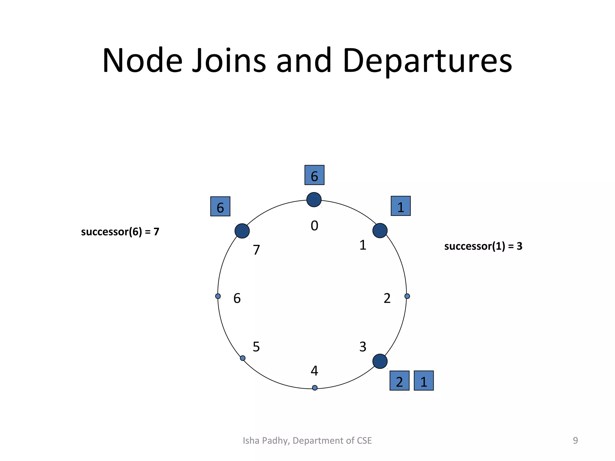
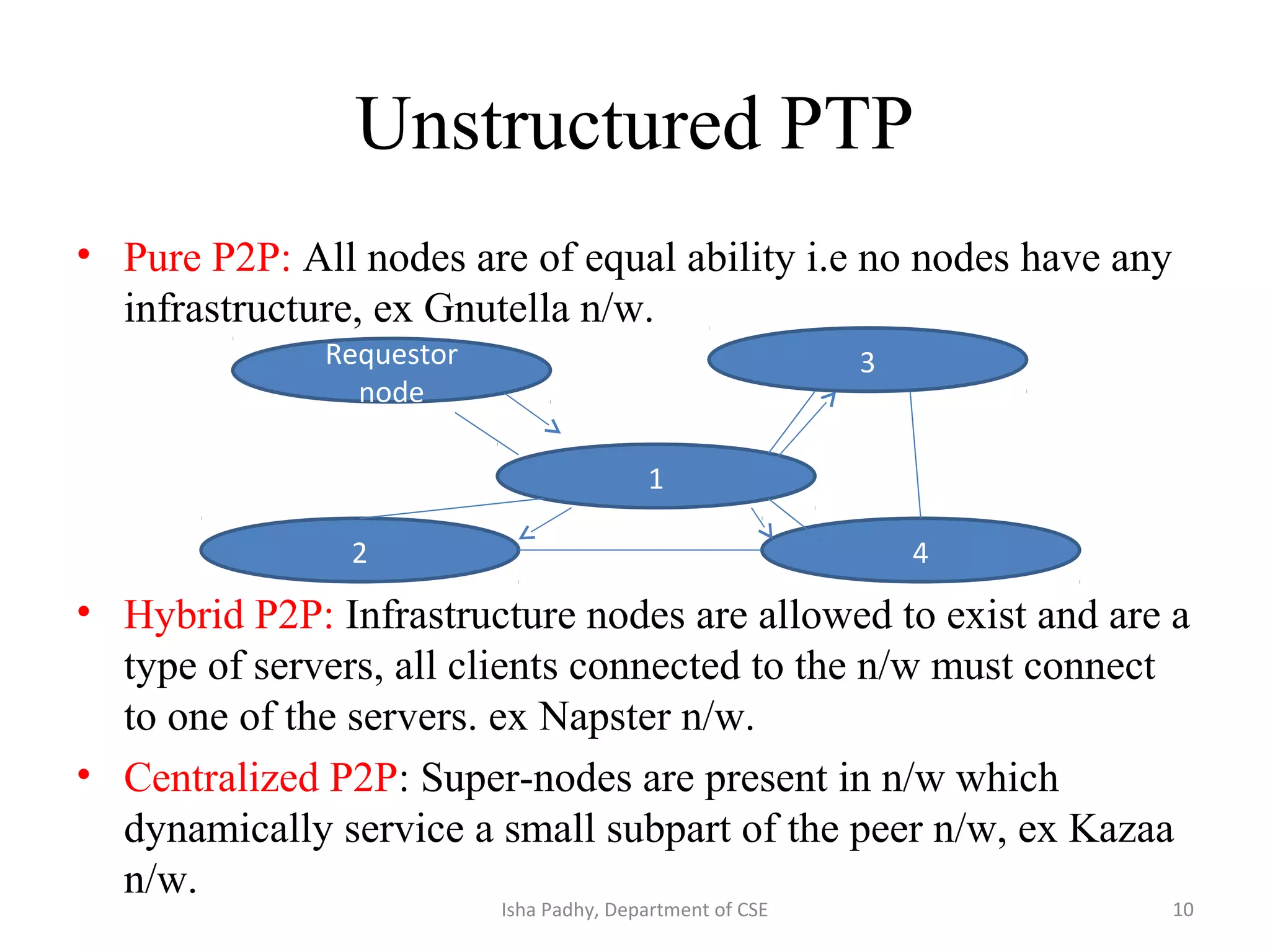
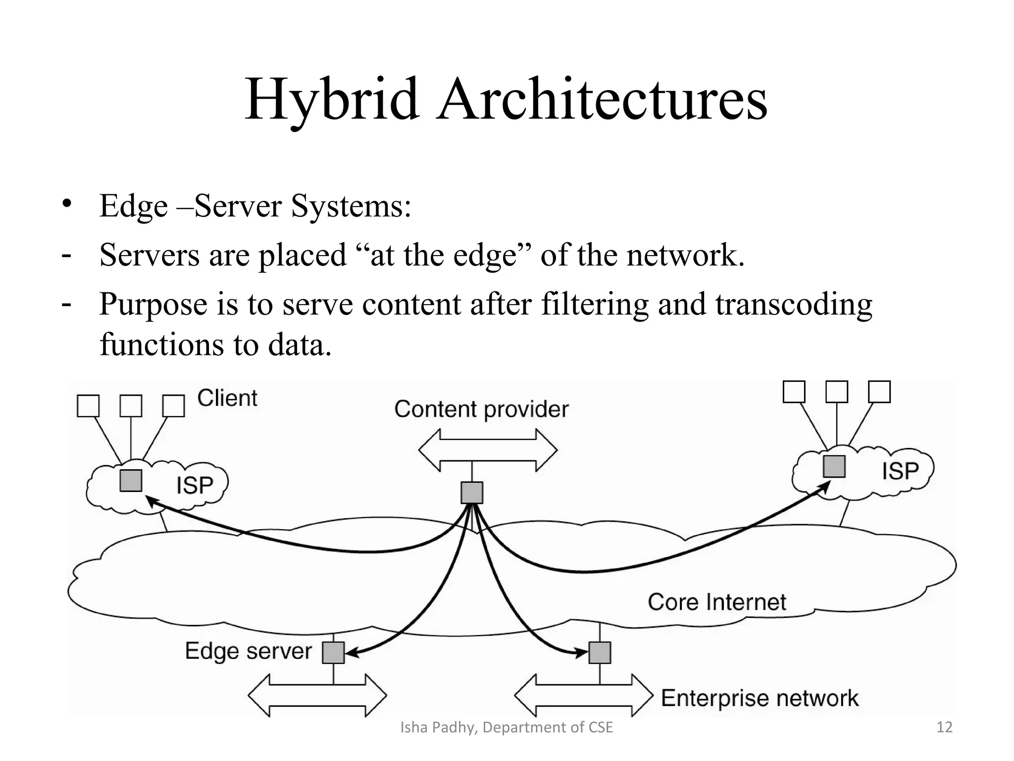
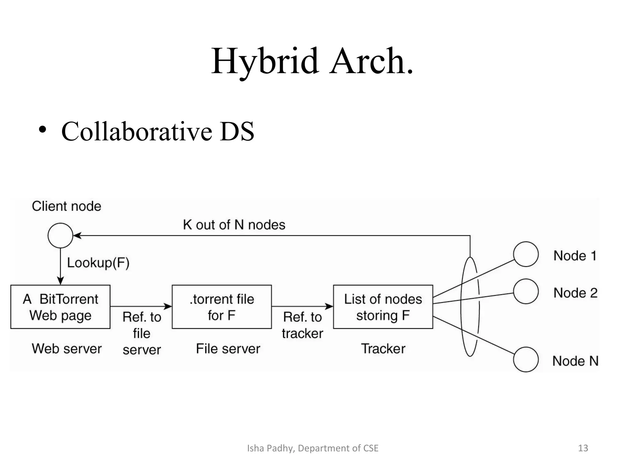
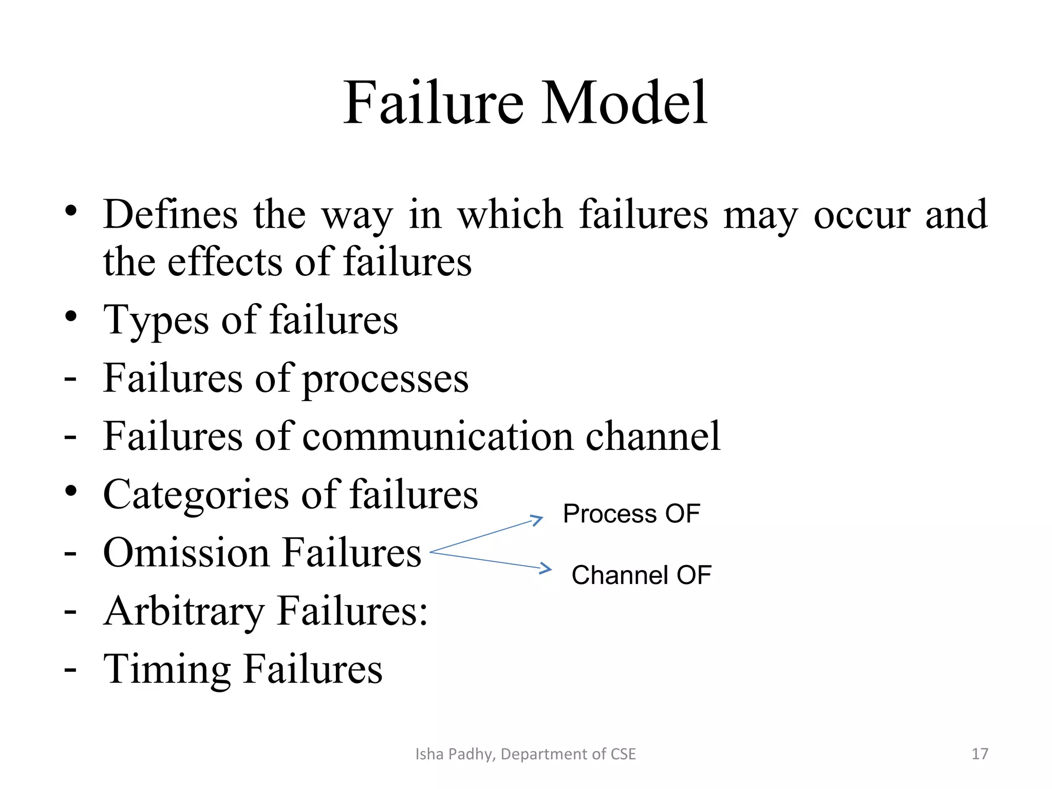
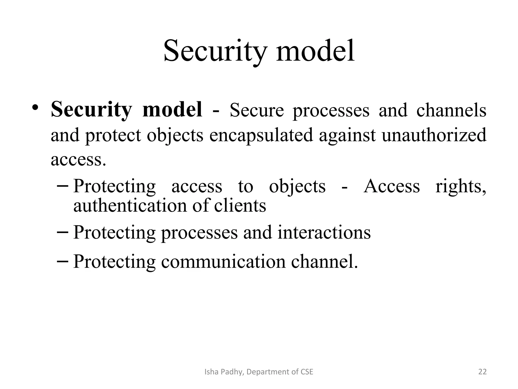
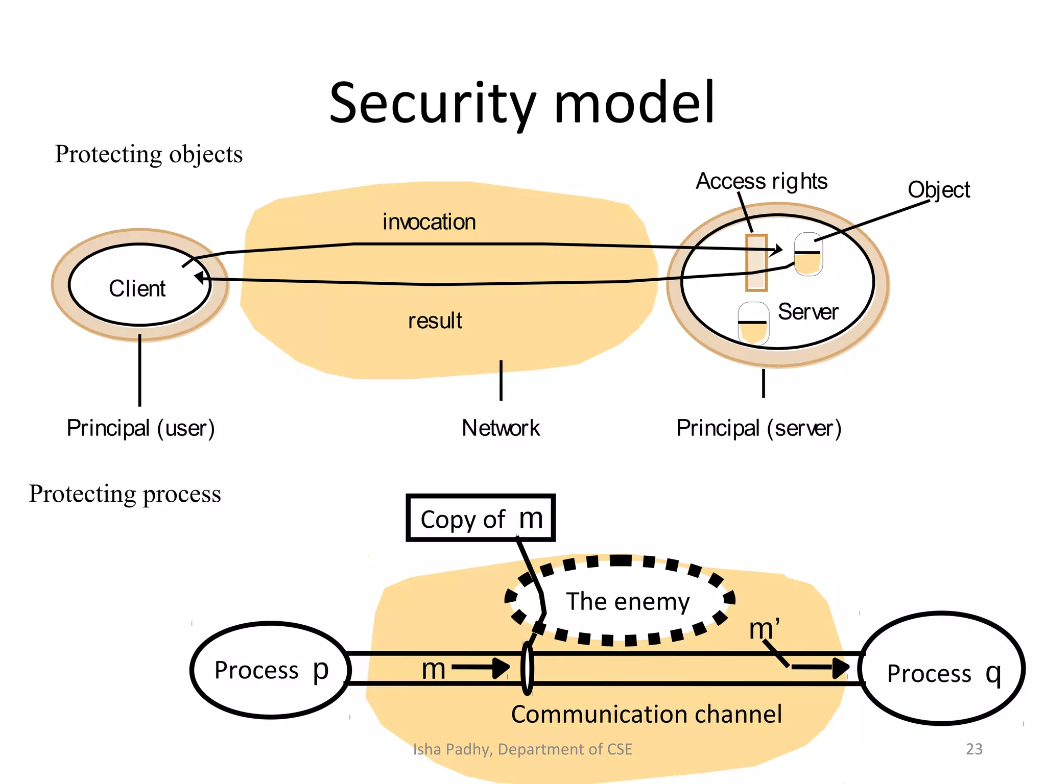
Tiered Architecture
• Technique to organize functionality of a given
layer and place this functionality into
appropriate servers.
• The functional decomposition is as
- Presentation Logic : Concerned with user
handling
- Application Logic: Detailed application –
specific processing
- Data Logic: persistent storage of application
Isha Padhy, Department of CSE 1
2 tier Architecture
• Server provides processing and data management; client provides simple graphical
display (thin-client)
• At the other extreme, all application processing and some data resides at the client
(fat-client approach)
Isha Padhy, Department of CSE 2
Two- tier architecture
• Advantages:
1.Because of tight coupling the application runs
faster.
2.Low latency in terms of interaction.
• Disadvantage:
Invoking a part of process from other part
across the process boundary is difficult.
• Example- Railway reservation: User is using
railway reservation software, gives input and
then sends request to server. 3Isha Padhy, Department of CSE
3 Tier Architecture
An example of a server acting as client.
-In some applications servers may also need to be clients, leading to a three level
architecture. Ex. Web servers that interact with database servers
-Presentation logic: UI part of application, allows user to input data.
-Application Logic: All business logic is written like data insertion, validation etc
-Data Logic: Contains method to interact with database.
Isha Padhy, Department of CSE 4
De-centralized Architecture
• Vertical distribution: Logically different components are
placed on different machines.
• Horizontal Distribution/ Peer to peer: All nodes are
independent and work on its share of data set.
- Why it was developed?
Network and computing resources owned by the users of a
service could also be utilized to support that service.
- Two types depending on how to organize the processes in a
n/w.
1. Structured
2. Unstructured
5Isha Padhy, Department of CSE
Structured
• N/w constructed using a procedure where
processes are organized using distributed hash
table(DHT).
• DHT provides a look- up service where (key,
value) pairs are stored. Data are assigned a
random key from identifier space, nodes are
assigned values from the same space.
• Responsibility for mapping from keys to
values is distributed among nodes.
• Ex Chord system 6Isha Padhy, Department of CSE
What is Chord?
• Steps in chord:
1. Find a value:
- Nodes are organized in a ring s.t. data item with key ‘k’ is mapped to node
with smallest identifier id~k. This node is called successor of key ‘k’,
Succ(k).
- A function is called to lookup for ‘k’ i.e LOOKUP(k) which returns n/w
address of succ(k)
2. Node joins a system: process starts with generating a random identifier
‘id’. Node that joins get ‘id’. Node does lookup(id) and gets n/w address of
succ(id). Then it inserts itself into ring.
3. Leaving: Node informs its departure to its predecessor and successor and
transfers its data to successor of node.
7Isha Padhy, Department of CSE
8
6
1
2
6
0
4
26
5
1
3
7
2
identifier
circle
identifier
node
X key
The Chord algorithm
successor(1) = 1
successor(2) = 3successor(6) = 0
Solves problem of locating a data item in a
collection of distributed nodes,
considering frequent node arrivals and
departures
Isha Padhy, Department of CSE
9
Node Joins and Departures
6
1
2
0
4
26
5
1
3
7
successor(6) = 7
6
1
successor(1) = 3
Isha Padhy, Department of CSE
Unstructured PTP
• Pure P2P: All nodes are of equal ability i.e no nodes have any
infrastructure, ex Gnutella n/w.
• Hybrid P2P: Infrastructure nodes are allowed to exist and are a
type of servers, all clients connected to the n/w must connect
to one of the servers. ex Napster n/w.
• Centralized P2P: Super-nodes are present in n/w which
dynamically service a small subpart of the peer n/w, ex Kazaa
n/w.
Requestor
node
3
2
1
4
10Isha Padhy, Department of CSE
Placement of objects and services
• Mapping of services to multiple servers: Servers may –
1. Partition of set of objects on which service is based
2. Replicate copies of them on several hosts
• Caching- Cache can be present in client side or proxy servers
that stores the recentlt used data objects
• Mobile code- applet code is stored in web server which can be
downloaded to a browser and run.
• Mobile agents- Composition of software and data that can
migrate from one system to other.
11Isha Padhy, Department of CSE
Hybrid Architectures
• Edge –Server Systems:
- Servers are placed “at the edge” of the network.
- Purpose is to serve content after filtering and transcoding
functions to data.
12Isha Padhy, Department of CSE
Hybrid Arch.
• Collaborative DS
13Isha Padhy, Department of CSE
Fundamental Model
• The purpose is
- All relevant assumptions about the DS can be made
- With the assumptions what are the possibilities
• Aspects to be considered are:
- Interaction: Considers the delay time taken by the
message from one process to other.
- Failure: Defines and classifies fault so design a system
to tolerate fault.
- Security: Analysis of threats to a system is done so that
system resists them.
14Isha Padhy, Department of CSE
Interaction Model
• Two factors affecting interaction of processes in DS
are:
- Performance of communication channels
- -Latency
- -Bandwidth
- -Jitter : Variation of time within two set of strings
transferred.
- Computer clocks and timing events : Two processes
running on different machines have different local
time and timestamps. So a global time standard is
used.
Time taken by first string of bits to reach
destination.
Congestion in network
Time taken by OS services in sending and
receiving side.
15Isha Padhy, Department of CSE
Interaction Model
• Two variants of IM
- Synchronous DS
--Strong assumption of time
--Bounds are defined for
1. Time to execute each step of a process which has known
lower and upper bounds
2. Each message transmitted over a channel is received within
a known bounded time
3. Each process has a local clock whose drift rate from real
time has a known bound.
- Asynchronous DS:
--Makes no assumption of time
16Isha Padhy, Department of CSE
Failure Model
• Defines the way in which failures may occur and
the effects of failures
• Types of failures
- Failures of processes
- Failures of communication channel
• Categories of failures
- Omission Failures
- Arbitrary Failures:
- Timing Failures
Process OF
Channel OF
17Isha Padhy, Department of CSE
Process has crashed i.e halted and will not
execute further.
Services execute properly if:
1.Processes either execute correctly or stop.
2.Follow time- outs i.e. a process allows a fixed
period of time for something to occur.
Process Omission Failures
18Isha Padhy, Department of CSE
Communication OF
Process p Process q
Communication channel
send
Outgoing message buffer Incoming message buffer
receivem
Failure occurs when a message is not transported from process ‘p’ outgoing
buffer to process ‘q’ incoming buffer due to lack of buffer space or n/w
transmission error.
19Isha Padhy, Department of CSE
Arbitrary Failures
• Arbitrarily omits intended processing steps or
takes unintended steps.
• Ex , A process may set wrong values in its data
items or may return a wrong value in
response.
• AF are uncommon in channels.
20Isha Padhy, Department of CSE
Timing Failures
• Synchronous DS:
- Failure of clock on process : Process local
clock exceeds the bound on its rate of drift
from real time.
- Failure of performance on process: Process
exceeds the interval between two steps
- Failure of performance on channel: A
message’s transmission takes longer time
• Asynchronous DS: Overloaded server may
respond late. 21Isha Padhy, Department of CSE
Security model
• Security model - Secure processes and channels
and protect objects encapsulated against unauthorized
access.
– Protecting access to objects - Access rights,
authentication of clients
– Protecting processes and interactions
– Protecting communication channel.
22Isha Padhy, Department of CSE
Security model
Network
invocation
result
Client
Server
Principal (user) Principal (server)
ObjectAccess rights
Communication channel
Copy of m
Process p Process qm
The enemy
m’
Protecting objects
Protecting process
23Isha Padhy, Department of CSE
Protecting channel
• Client and server knows the identity of each
other( Authentication Process)
• Secure channel ensures privacy and integrity
of data( cryptography process)
• Each message includes a logical timestamp to
prevent messages from being reordered.
24Isha Padhy, Department of CSE

System models 2 in distributed system

  • 1.
    Tiered Architecture • Techniqueto organize functionality of a given layer and place this functionality into appropriate servers. • The functional decomposition is as - Presentation Logic : Concerned with user handling - Application Logic: Detailed application – specific processing - Data Logic: persistent storage of application Isha Padhy, Department of CSE 1
  • 2.
    2 tier Architecture •Server provides processing and data management; client provides simple graphical display (thin-client) • At the other extreme, all application processing and some data resides at the client (fat-client approach) Isha Padhy, Department of CSE 2
  • 3.
    Two- tier architecture •Advantages: 1.Because of tight coupling the application runs faster. 2.Low latency in terms of interaction. • Disadvantage: Invoking a part of process from other part across the process boundary is difficult. • Example- Railway reservation: User is using railway reservation software, gives input and then sends request to server. 3Isha Padhy, Department of CSE
  • 4.
    3 Tier Architecture Anexample of a server acting as client. -In some applications servers may also need to be clients, leading to a three level architecture. Ex. Web servers that interact with database servers -Presentation logic: UI part of application, allows user to input data. -Application Logic: All business logic is written like data insertion, validation etc -Data Logic: Contains method to interact with database. Isha Padhy, Department of CSE 4
  • 5.
    De-centralized Architecture • Verticaldistribution: Logically different components are placed on different machines. • Horizontal Distribution/ Peer to peer: All nodes are independent and work on its share of data set. - Why it was developed? Network and computing resources owned by the users of a service could also be utilized to support that service. - Two types depending on how to organize the processes in a n/w. 1. Structured 2. Unstructured 5Isha Padhy, Department of CSE
  • 6.
    Structured • N/w constructedusing a procedure where processes are organized using distributed hash table(DHT). • DHT provides a look- up service where (key, value) pairs are stored. Data are assigned a random key from identifier space, nodes are assigned values from the same space. • Responsibility for mapping from keys to values is distributed among nodes. • Ex Chord system 6Isha Padhy, Department of CSE
  • 7.
    What is Chord? •Steps in chord: 1. Find a value: - Nodes are organized in a ring s.t. data item with key ‘k’ is mapped to node with smallest identifier id~k. This node is called successor of key ‘k’, Succ(k). - A function is called to lookup for ‘k’ i.e LOOKUP(k) which returns n/w address of succ(k) 2. Node joins a system: process starts with generating a random identifier ‘id’. Node that joins get ‘id’. Node does lookup(id) and gets n/w address of succ(id). Then it inserts itself into ring. 3. Leaving: Node informs its departure to its predecessor and successor and transfers its data to successor of node. 7Isha Padhy, Department of CSE
  • 8.
    8 6 1 2 6 0 4 26 5 1 3 7 2 identifier circle identifier node X key The Chordalgorithm successor(1) = 1 successor(2) = 3successor(6) = 0 Solves problem of locating a data item in a collection of distributed nodes, considering frequent node arrivals and departures Isha Padhy, Department of CSE
  • 9.
    9 Node Joins andDepartures 6 1 2 0 4 26 5 1 3 7 successor(6) = 7 6 1 successor(1) = 3 Isha Padhy, Department of CSE
  • 10.
    Unstructured PTP • PureP2P: All nodes are of equal ability i.e no nodes have any infrastructure, ex Gnutella n/w. • Hybrid P2P: Infrastructure nodes are allowed to exist and are a type of servers, all clients connected to the n/w must connect to one of the servers. ex Napster n/w. • Centralized P2P: Super-nodes are present in n/w which dynamically service a small subpart of the peer n/w, ex Kazaa n/w. Requestor node 3 2 1 4 10Isha Padhy, Department of CSE
  • 11.
    Placement of objectsand services • Mapping of services to multiple servers: Servers may – 1. Partition of set of objects on which service is based 2. Replicate copies of them on several hosts • Caching- Cache can be present in client side or proxy servers that stores the recentlt used data objects • Mobile code- applet code is stored in web server which can be downloaded to a browser and run. • Mobile agents- Composition of software and data that can migrate from one system to other. 11Isha Padhy, Department of CSE
  • 12.
    Hybrid Architectures • Edge–Server Systems: - Servers are placed “at the edge” of the network. - Purpose is to serve content after filtering and transcoding functions to data. 12Isha Padhy, Department of CSE
  • 13.
    Hybrid Arch. • CollaborativeDS 13Isha Padhy, Department of CSE
  • 14.
    Fundamental Model • Thepurpose is - All relevant assumptions about the DS can be made - With the assumptions what are the possibilities • Aspects to be considered are: - Interaction: Considers the delay time taken by the message from one process to other. - Failure: Defines and classifies fault so design a system to tolerate fault. - Security: Analysis of threats to a system is done so that system resists them. 14Isha Padhy, Department of CSE
  • 15.
    Interaction Model • Twofactors affecting interaction of processes in DS are: - Performance of communication channels - -Latency - -Bandwidth - -Jitter : Variation of time within two set of strings transferred. - Computer clocks and timing events : Two processes running on different machines have different local time and timestamps. So a global time standard is used. Time taken by first string of bits to reach destination. Congestion in network Time taken by OS services in sending and receiving side. 15Isha Padhy, Department of CSE
  • 16.
    Interaction Model • Twovariants of IM - Synchronous DS --Strong assumption of time --Bounds are defined for 1. Time to execute each step of a process which has known lower and upper bounds 2. Each message transmitted over a channel is received within a known bounded time 3. Each process has a local clock whose drift rate from real time has a known bound. - Asynchronous DS: --Makes no assumption of time 16Isha Padhy, Department of CSE
  • 17.
    Failure Model • Definesthe way in which failures may occur and the effects of failures • Types of failures - Failures of processes - Failures of communication channel • Categories of failures - Omission Failures - Arbitrary Failures: - Timing Failures Process OF Channel OF 17Isha Padhy, Department of CSE
  • 18.
    Process has crashedi.e halted and will not execute further. Services execute properly if: 1.Processes either execute correctly or stop. 2.Follow time- outs i.e. a process allows a fixed period of time for something to occur. Process Omission Failures 18Isha Padhy, Department of CSE
  • 19.
    Communication OF Process pProcess q Communication channel send Outgoing message buffer Incoming message buffer receivem Failure occurs when a message is not transported from process ‘p’ outgoing buffer to process ‘q’ incoming buffer due to lack of buffer space or n/w transmission error. 19Isha Padhy, Department of CSE
  • 20.
    Arbitrary Failures • Arbitrarilyomits intended processing steps or takes unintended steps. • Ex , A process may set wrong values in its data items or may return a wrong value in response. • AF are uncommon in channels. 20Isha Padhy, Department of CSE
  • 21.
    Timing Failures • SynchronousDS: - Failure of clock on process : Process local clock exceeds the bound on its rate of drift from real time. - Failure of performance on process: Process exceeds the interval between two steps - Failure of performance on channel: A message’s transmission takes longer time • Asynchronous DS: Overloaded server may respond late. 21Isha Padhy, Department of CSE
  • 22.
    Security model • Securitymodel - Secure processes and channels and protect objects encapsulated against unauthorized access. – Protecting access to objects - Access rights, authentication of clients – Protecting processes and interactions – Protecting communication channel. 22Isha Padhy, Department of CSE
  • 23.
    Security model Network invocation result Client Server Principal (user)Principal (server) ObjectAccess rights Communication channel Copy of m Process p Process qm The enemy m’ Protecting objects Protecting process 23Isha Padhy, Department of CSE
  • 24.
    Protecting channel • Clientand server knows the identity of each other( Authentication Process) • Secure channel ensures privacy and integrity of data( cryptography process) • Each message includes a logical timestamp to prevent messages from being reordered. 24Isha Padhy, Department of CSE