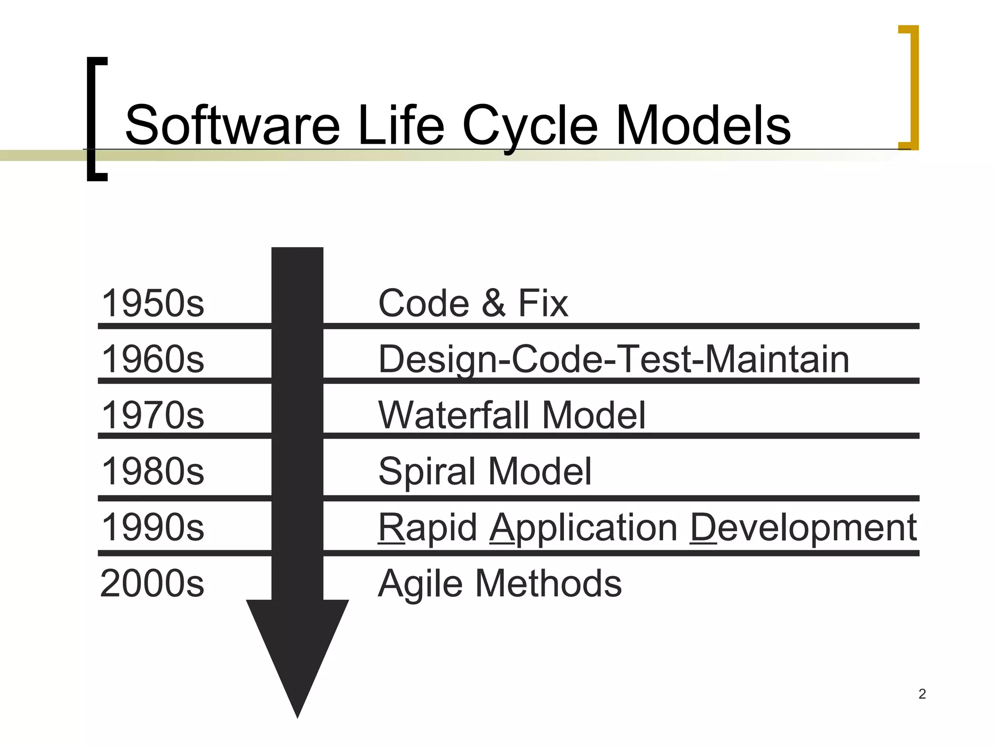
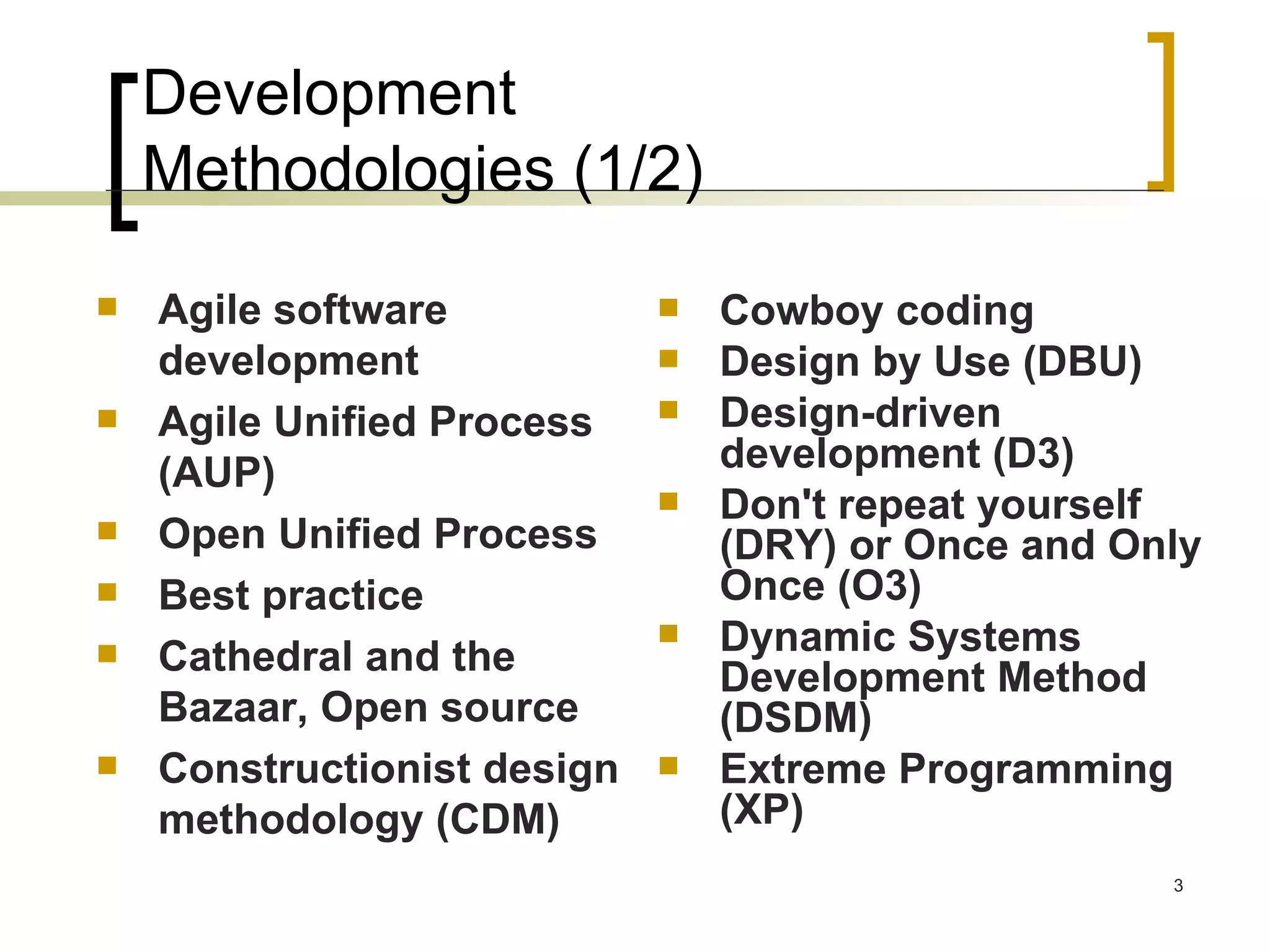
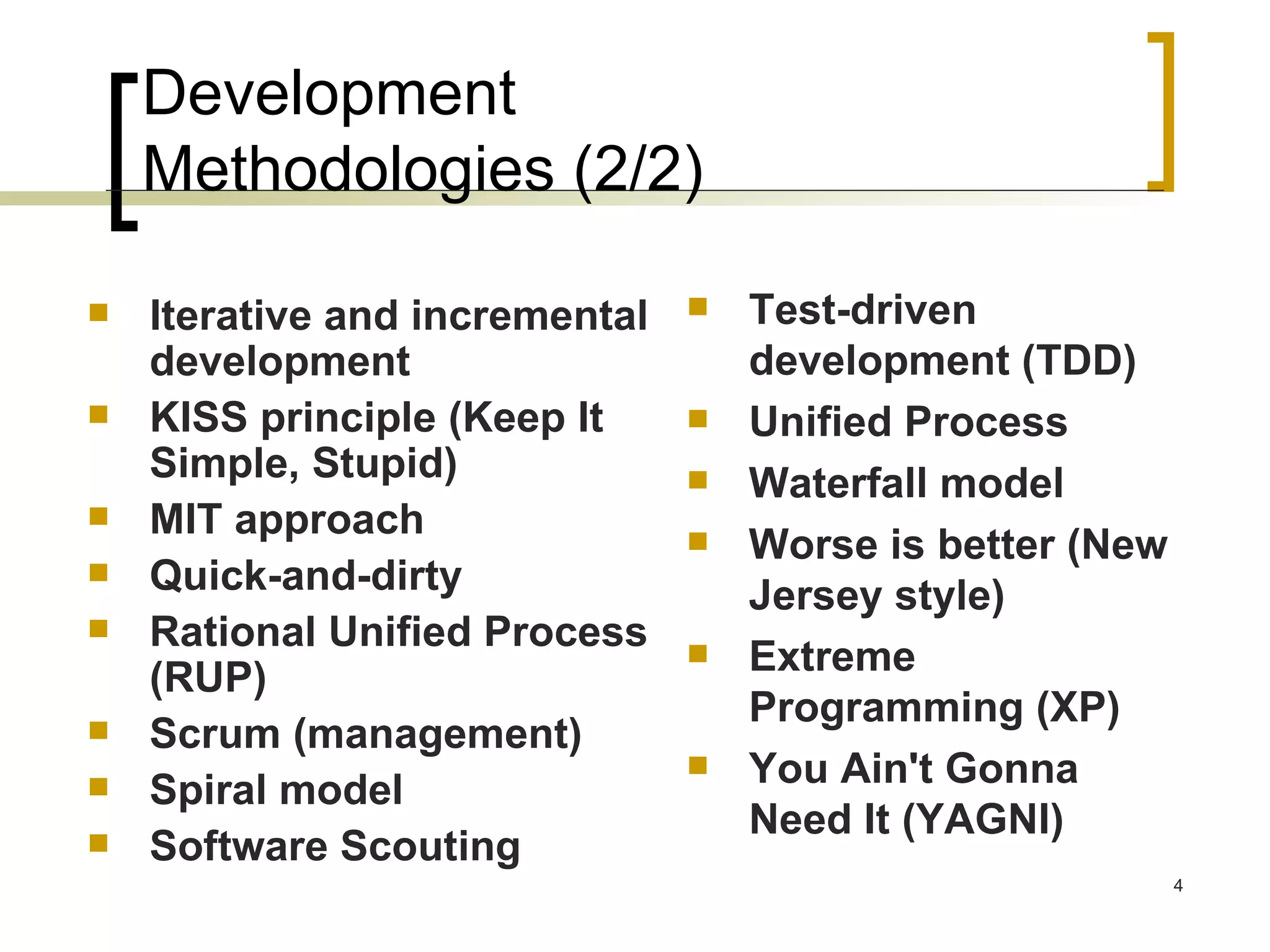
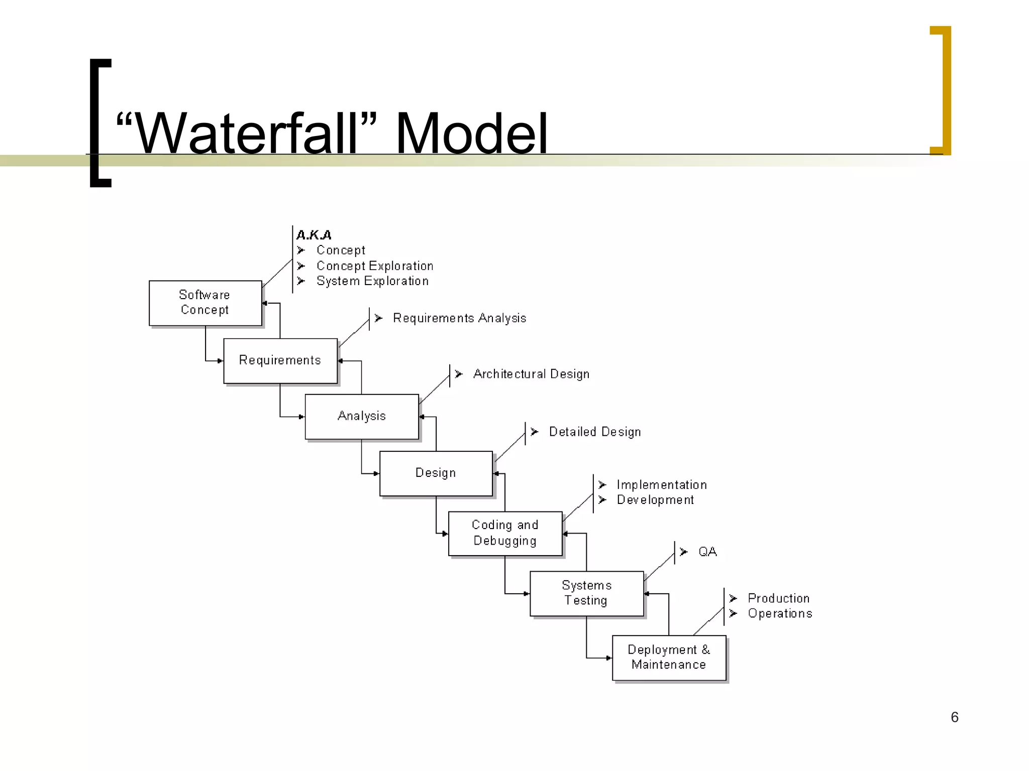
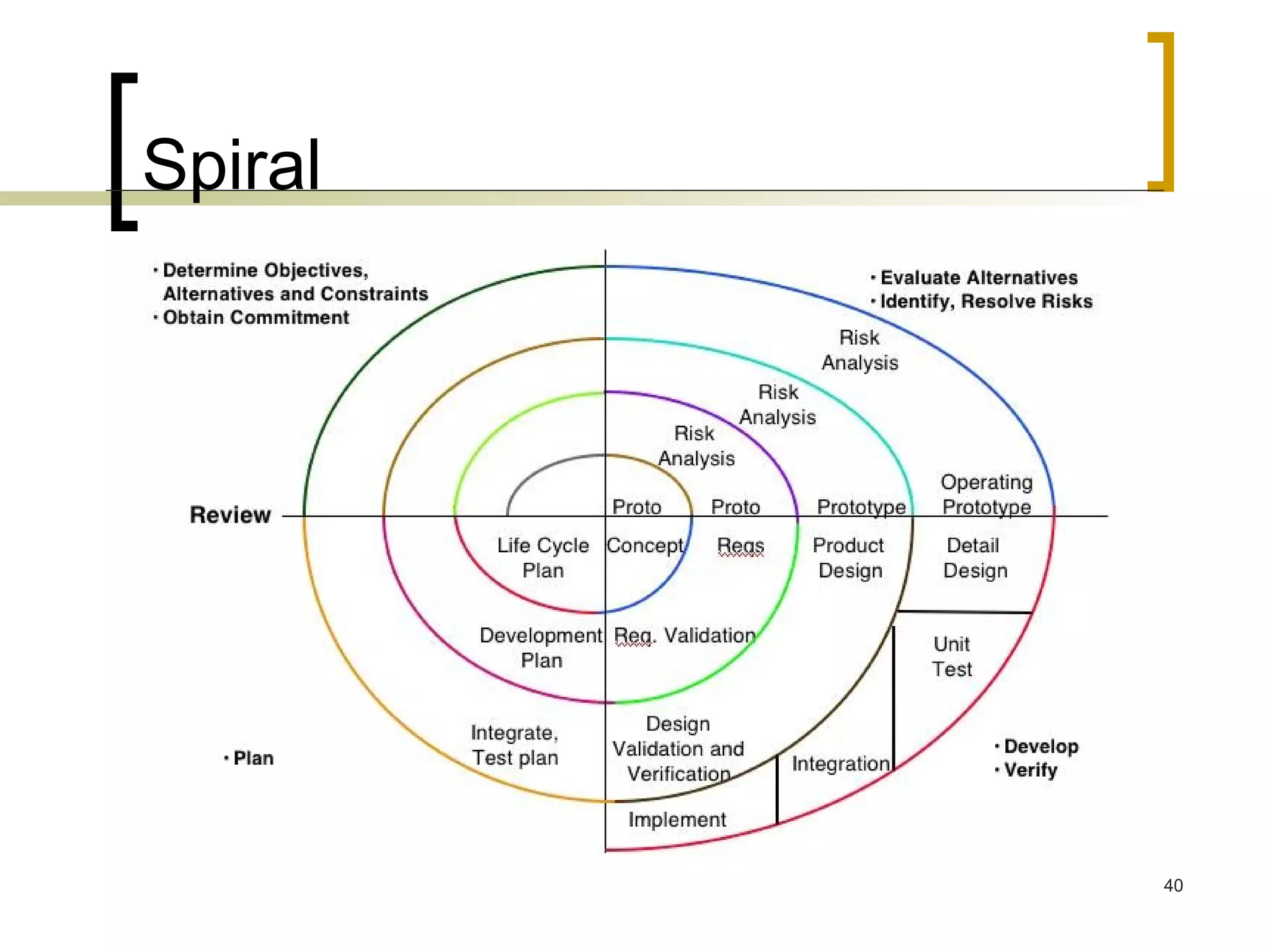
Design Methodologies
Software Life Cycle Models 1950s  Code & Fix 1960s  Design-Code-Test-Maintain 1970s  Waterfall Model 1980s  Spiral Model 1990s  R apid  A pplication  D evelopment 2000s  Agile Methods
Development  Methodologies (1/2) Agile software development  Agile Unified Process (AUP)  Open Unified Process  Best practice  Cathedral and the Bazaar, Open source  Constructionist design methodology (CDM)  Cowboy coding  Design by Use (DBU)  Design-driven development (D3)  Don't repeat yourself (DRY) or Once and Only Once (O3)  Dynamic Systems Development Method (DSDM)  Extreme Programming (XP)
Development  Methodologies (2/2) Test-driven development (TDD)  Unified Process  Waterfall model  Worse is better (New Jersey style)  Extreme Programming (XP)  You Ain't Gonna Need It (YAGNI)  Iterative and incremental development  KISS principle (Keep It Simple, Stupid)  MIT approach Quick-and-dirty  Rational Unified Process (RUP)  Scrum (management)  Spiral model  Software Scouting
Code-and-Fix “ Code-like-Hell” Specification (maybe), Code (yes), Release (maybe) Advantages No overhead Requires little expertise Disadvantages No process, quality control, etc. Highly risky Suitable for prototypes or throwaways
“Waterfall” Model
Activities by % of Total Effort NASA’s “Manager’s Handbook for Software Development”
Potential Deliverables by Phase
Concept Exploration The “Why” phase Not a “mandatory formal” phase Sometimes called the “pre-project” phase Collecting project ideas Then the “funneling” process Project Justification ROI Cost-benefit analysis Project Portfolio Matrix Initial planning and estimates
Concept Exploration Possibly includes Procurement Management: RFP Process Vendor selection Contract management Gathering the initial team Including PM if not already on-board Identify the project sponsor Primary contact for approval and decision making Potential Phase Outputs:  Concept Document, Product Description, Proposal, SOW, Project Charter
Concept Exploration Characteristics & Issues Lack of full commitment and leadership Some frustrations: Management only getting rough estimates from development Development not getting enough specifics from customer Finding a balanced team Budget sign-off may be your 1 st  major task Achieved via: Good concept document or equivalent Demonstration of clear need (justification) Initial estimates
Requirements The “What” phase Inputs: SOW, Proposal Outputs:  Requirements Document (RD) a.k.a.Requirements Specification Document (RSD) Software Requirements Specification (SRS) 1 st  Project Baseline Software Project Management Plan (SPMP) Requirements Approval & Sign-Off Your most difficult task in this phase
Requirements Perhaps most important & difficult phase Shortchanging it is a ‘classic mistake’ Can begin with a Project Kickoff Meeting Can end with a Software Requirements Review (SRR) For Sponsor and/or customer(s) approval
Why are Requirements so Important?
Requirements Characteristics & Issues Conflict of interest: developer vs. customer Potential tug-of-war: Disagreement on Features & Estimates Especially in fixed-price contracts Frequent requirements changes Achieving sign-off Project planning occurs in parallel
Requirements  Requirements are capabilities and condition to which the system – more broadly, the project – must conform
2 Types of Requirements Functional  (behavioral) Features and capabilities Non-functional  (a.k.a. “technical”) (everything else) Usability Human factors, help, documentation Reliability Failure rates, recoverability, availability Performance Response times, throughput, resource usage Supportability Maintainability, internationalization Operations: systems management, installation Interface: integration with other systems Other: legal, packaging, hardware
Requirements Other ways of categorizing Go-Ahead vs. Catch-up  Relative to competition Backward-looking vs. Forward-looking Backward: address issues with previous version Forward: Anticipating future needs of customers Must be prioritized Must-have Should-have Could-have (Nice-to-have: NTH) Must be approved
Analysis & Design The “How” Phases Inputs: Requirements Document Outputs:  Functional Specification  Detailed Design Document  User Interface Specification  Data Model Prototype (can also be done with requirements) Updated Plan (improved estimates; new baseline)
Analysis & Design a.k.a. Top-level design & detailed design Continues process from RD Ends with Critical Design Review (CDR) Formal sign-off Can also include earlier Preliminary Design Review (PDR) for high level design
Development The “Do It” phase Coding & Unit testing Often overlaps Design & Integration phases To shorten the overall schedule PM needs to coordinate this
Development Other concurrent activities Design completion Integration begins Unit testing of individual components Test bed setup (environment and tools) Project plans updated Scope and Risk Management conducted
Development Characteristics Pressure increases Staffing at highest levels Often a “heads-down” operation Issues Last-minute changes Team coordination (esp. in large projects) Communication overhead Management of sub-contractors
Integration & Test Evolves from Dev. Phase Often done as 2 parallel phases Partial integration & initial test Starts with integration of modules An initial, incomplete version constructed Progressively add more components
Integration & Test Integration primarily a programmer task Test primarily a QA team task Integration: Top-down: Core functionality first, empty shells for incomplete routines (stubs) Bottom up: gradually bind low-level modules Prefer top-down generally
Integration & Test Tests Integration testing Black & White-box testing Load & Stress testing Alpha & Beta testing Acceptance testing Other activities Final budgeting; risk mgmt.; training; installation preparation; team reduced
Integration & Test Characteristics & Issues Increased pressure Overtime Customer conflicts over features Frustration over last-minute failures Budget overruns Motivation problems (such as burnout) Difficulty in customer acceptance Esp. true for fixed-price contracts
Deployment & Maintenance Installation depends on system type Web-based, CD-ROM, in-house, etc. Migration strategy How to get customers up on the system Parallel operation Deployment typically in your project plan, maintenance not
Deployment & Maintenance Maintenance Fix defects Add new features Improve performance Configuration control is very important here Documents need to be maintained also Sometimes a single team maintains multiple products
Deployment & Maintenance Characteristics & Issues Lack of enthusiasm  Pressure for quick fixes Insufficient budget Too many patches Personnel turnover Regression testing is critical Preferably through automated tools
Lifecycle Planning a.k.a. Lifecycle Management or SDLC Greatly influences your chance of success Not choosing a lifecycle is a bad option Three primary lifecycle model components  Phases and their order Intermediate products of each phase Reviews used in each phase
Lifecycle Planning Different projects require different approaches You do not need to know all models by name You should know how that if given a certain scenario what sort of SDLC would be appropriate There are more than covered here A lifecycle is not a design, modeling or diagramming technique  The same technique (UML, DFD, etc) can be used with multiple lifecycles
Pure Waterfall The “granddaddy” of models Linear sequence of phases “Pure” model: no phases overlap Document driven All planning done up-front
Waterfall Risk Why does the waterfall model “invite risk”? Integration and testing occur at the end Often anyone’s 1 st  chance to “see” the program
Pure Waterfall Works well for projects with Stable product definition Well-understood technologies Quality constraints stronger than cost & schedule Technically weak staff Provides structure Good for overseas projects
Pure Waterfall Disadvantages Not flexible Rigid march from start->finish Difficult to fully define requirements up front Can produce excessive documentation Few visible signs of progress until the end
SSADM Only covers part of the system development process, i.e. analysis and design. It emphasises the importance of the correct determination of systems requirements.
SSADM Stages Feasibility Study Stage 0 – Feasibility Requirements Analysis Stage 1 – Investigation of current requirements Stage 2 – Business Systems Options Requirements Specification Stage 3 – Definition of Requirements
SSADM Stages Logical System Specification Stage 4 – Technical System Options Stage 5 – Logical Design Physical Design Stage 6 – Physical Design
Spiral
Spiral Emphasizes risk analysis & mgmt. in each phase  A Series of Mini-projects Each addresses a set of “risks” Start small, explore risks, prototype, plan, repeat Early iterations are “cheapest” Number of spirals is variable Last set of steps are waterfall-like
Spiral Advantages Can be combined with other models As costs increase, risks decrease Risk orientation provides early warning Disadvantages More complex Requires more management
Evolutionary Prototyping Design most prominent parts first Usually via a visual prototype Good for situations with: Rapidly changing requirements Non-committal customer Vague problem domain Provides steady, visible progress Disadvantages Time estimation is difficult Project completion date may be unknown An excuse to do “code-and-fix”
Staged Delivery Waterfall steps through architectural design Then detailed design, code, test, deliver in stages Advantages Customers get product much sooner Tangible signs of progress sooner Problems discovered earlier Increases flexibility Reduces: status reporting overhead & estimation error Disadvantages Requires more planning (for you the PM) More releases increase effort (and possible feature creep) How’s this differ from Evolutionary Prototyping?
V Process Model
V Process Model
V Process Model Designed for testability Emphasizes Verification & Validation Variation of waterfall Strengths Encourages V&V at all phases Weaknesses Does not handle iterations Changes can be more difficult to handle Good choice for systems that require high reliability such as patient control systems
RAD Rapid Application Development Popular in the 80’s 1. Joint Requirements Planning (JRP) 2. Joint Application Design (JAD) 3. Construction  Heavy use of tools: code generators Time-boxed; many prototypes 4. Cutover Good for systems with extensive user input available
XP: eXtreme Programming Not a Microsoft product Part of movement called “Agile Development” A “Lightweight” methodology A bit counter-culture Currently in vogue Motto: “Embrace Change” Highly Incremental / Iterative
eXtreme Programming
eXtreme Programming Suitable for small groups Attempts to minimize unnecessary work Uses an “on-site” customer Small releases Pair programming Refactoring Stories as requirements You want good developers if you use this
Other “Agile” Methodologies Agile here means “lite”, reduced docs, highly iterative Agile Software Development SCRUM Features 30-day “Sprint” cycles Feature Driven Development (FDD) XP with more emphasis on docs and process
Other “Agile” Methodologies Adaptive Software Development (ASD) Dynamic System Development Method (DSDM) Popular in Europe Homegrown: developers often hide their “agile adventures” from management
Other “Agile” Methodologies Pros Similar to XP, can reduce process overhead Responsive to user feedback Amenable to change Cons Requires close monitoring by PM May not “scale” to large projects Often requires better quality developers
Rational Unified Process RUP From Rational Corporation “Generic” version is the Unified Process Commercial Extensive tool support (expensive) Object-oriented Incremental Newer
Rational Unified Process
Rational Unified Process Develop Iteratively Manage Requirements Uses UML (Unified Modeling Language) Produces “artifacts” Use component-based architecture Visually model software Complex process A “framework” Suitable for large scale systems
Choosing Your Lifecycle Varies by project Opt for “iterative” or “incremental”  How well are requirements understood? What are the risks? Is there a fixed deadline? How experienced is the team or customer?
IEEE 1074 A standard for developing software processes Lifecycle model selection Project management process Predevelopment processes Development processes Post-development processes Integral process
Unified Modelling Language
Use cases diagram UML 2 Use cases diagrams  describes the behavior of the target system from an external point of view. Use cases describe "the meat" of the actual requirements. Use cases . A use case describes a sequence of actions that provide something of measurable value to an actor and is drawn as a horizontal ellipse.  Actors . An actor is a person, organization, or external system that plays a role in one or more interactions with your system. Actors are drawn as stick figures.  Associations .  Associations between actors and use cases are indicated by solid lines. An association exists whenever an actor is involved with an interaction described by a use case.
Use cases diagram
Use cases diagram
Use cases diagram
Class diagram UML class diagrams  show the classes of the system, their inter-relationships, and the operations and attributes of the classes Explore domain concepts in the form of a domain model  Analyze requirements in the form of a conceptual/analysis model  Depict the detailed design of object-oriented or object-based software
Class diagram
Class diagram

Software design methodologies

  • 1.
  • 2.
    Software Life CycleModels 1950s Code & Fix 1960s Design-Code-Test-Maintain 1970s Waterfall Model 1980s Spiral Model 1990s R apid A pplication D evelopment 2000s Agile Methods
  • 3.
    Development Methodologies(1/2) Agile software development Agile Unified Process (AUP) Open Unified Process Best practice Cathedral and the Bazaar, Open source Constructionist design methodology (CDM) Cowboy coding Design by Use (DBU) Design-driven development (D3) Don't repeat yourself (DRY) or Once and Only Once (O3) Dynamic Systems Development Method (DSDM) Extreme Programming (XP)
  • 4.
    Development Methodologies(2/2) Test-driven development (TDD) Unified Process Waterfall model Worse is better (New Jersey style) Extreme Programming (XP) You Ain't Gonna Need It (YAGNI) Iterative and incremental development KISS principle (Keep It Simple, Stupid) MIT approach Quick-and-dirty Rational Unified Process (RUP) Scrum (management) Spiral model Software Scouting
  • 5.
    Code-and-Fix “ Code-like-Hell”Specification (maybe), Code (yes), Release (maybe) Advantages No overhead Requires little expertise Disadvantages No process, quality control, etc. Highly risky Suitable for prototypes or throwaways
  • 6.
  • 7.
    Activities by %of Total Effort NASA’s “Manager’s Handbook for Software Development”
  • 8.
  • 9.
    Concept Exploration The“Why” phase Not a “mandatory formal” phase Sometimes called the “pre-project” phase Collecting project ideas Then the “funneling” process Project Justification ROI Cost-benefit analysis Project Portfolio Matrix Initial planning and estimates
  • 10.
    Concept Exploration Possiblyincludes Procurement Management: RFP Process Vendor selection Contract management Gathering the initial team Including PM if not already on-board Identify the project sponsor Primary contact for approval and decision making Potential Phase Outputs: Concept Document, Product Description, Proposal, SOW, Project Charter
  • 11.
    Concept Exploration Characteristics& Issues Lack of full commitment and leadership Some frustrations: Management only getting rough estimates from development Development not getting enough specifics from customer Finding a balanced team Budget sign-off may be your 1 st major task Achieved via: Good concept document or equivalent Demonstration of clear need (justification) Initial estimates
  • 12.
    Requirements The “What”phase Inputs: SOW, Proposal Outputs: Requirements Document (RD) a.k.a.Requirements Specification Document (RSD) Software Requirements Specification (SRS) 1 st Project Baseline Software Project Management Plan (SPMP) Requirements Approval & Sign-Off Your most difficult task in this phase
  • 13.
    Requirements Perhaps mostimportant & difficult phase Shortchanging it is a ‘classic mistake’ Can begin with a Project Kickoff Meeting Can end with a Software Requirements Review (SRR) For Sponsor and/or customer(s) approval
  • 14.
    Why are Requirementsso Important?
  • 15.
    Requirements Characteristics &Issues Conflict of interest: developer vs. customer Potential tug-of-war: Disagreement on Features & Estimates Especially in fixed-price contracts Frequent requirements changes Achieving sign-off Project planning occurs in parallel
  • 16.
    Requirements Requirementsare capabilities and condition to which the system – more broadly, the project – must conform
  • 17.
    2 Types ofRequirements Functional (behavioral) Features and capabilities Non-functional (a.k.a. “technical”) (everything else) Usability Human factors, help, documentation Reliability Failure rates, recoverability, availability Performance Response times, throughput, resource usage Supportability Maintainability, internationalization Operations: systems management, installation Interface: integration with other systems Other: legal, packaging, hardware
  • 18.
    Requirements Other waysof categorizing Go-Ahead vs. Catch-up Relative to competition Backward-looking vs. Forward-looking Backward: address issues with previous version Forward: Anticipating future needs of customers Must be prioritized Must-have Should-have Could-have (Nice-to-have: NTH) Must be approved
  • 19.
    Analysis & DesignThe “How” Phases Inputs: Requirements Document Outputs: Functional Specification Detailed Design Document User Interface Specification Data Model Prototype (can also be done with requirements) Updated Plan (improved estimates; new baseline)
  • 20.
    Analysis & Designa.k.a. Top-level design & detailed design Continues process from RD Ends with Critical Design Review (CDR) Formal sign-off Can also include earlier Preliminary Design Review (PDR) for high level design
  • 21.
    Development The “DoIt” phase Coding & Unit testing Often overlaps Design & Integration phases To shorten the overall schedule PM needs to coordinate this
  • 22.
    Development Other concurrentactivities Design completion Integration begins Unit testing of individual components Test bed setup (environment and tools) Project plans updated Scope and Risk Management conducted
  • 23.
    Development Characteristics Pressureincreases Staffing at highest levels Often a “heads-down” operation Issues Last-minute changes Team coordination (esp. in large projects) Communication overhead Management of sub-contractors
  • 24.
    Integration & TestEvolves from Dev. Phase Often done as 2 parallel phases Partial integration & initial test Starts with integration of modules An initial, incomplete version constructed Progressively add more components
  • 25.
    Integration & TestIntegration primarily a programmer task Test primarily a QA team task Integration: Top-down: Core functionality first, empty shells for incomplete routines (stubs) Bottom up: gradually bind low-level modules Prefer top-down generally
  • 26.
    Integration & TestTests Integration testing Black & White-box testing Load & Stress testing Alpha & Beta testing Acceptance testing Other activities Final budgeting; risk mgmt.; training; installation preparation; team reduced
  • 27.
    Integration & TestCharacteristics & Issues Increased pressure Overtime Customer conflicts over features Frustration over last-minute failures Budget overruns Motivation problems (such as burnout) Difficulty in customer acceptance Esp. true for fixed-price contracts
  • 28.
    Deployment & MaintenanceInstallation depends on system type Web-based, CD-ROM, in-house, etc. Migration strategy How to get customers up on the system Parallel operation Deployment typically in your project plan, maintenance not
  • 29.
    Deployment & MaintenanceMaintenance Fix defects Add new features Improve performance Configuration control is very important here Documents need to be maintained also Sometimes a single team maintains multiple products
  • 30.
    Deployment & MaintenanceCharacteristics & Issues Lack of enthusiasm Pressure for quick fixes Insufficient budget Too many patches Personnel turnover Regression testing is critical Preferably through automated tools
  • 31.
    Lifecycle Planning a.k.a.Lifecycle Management or SDLC Greatly influences your chance of success Not choosing a lifecycle is a bad option Three primary lifecycle model components Phases and their order Intermediate products of each phase Reviews used in each phase
  • 32.
    Lifecycle Planning Differentprojects require different approaches You do not need to know all models by name You should know how that if given a certain scenario what sort of SDLC would be appropriate There are more than covered here A lifecycle is not a design, modeling or diagramming technique The same technique (UML, DFD, etc) can be used with multiple lifecycles
  • 33.
    Pure Waterfall The“granddaddy” of models Linear sequence of phases “Pure” model: no phases overlap Document driven All planning done up-front
  • 34.
    Waterfall Risk Whydoes the waterfall model “invite risk”? Integration and testing occur at the end Often anyone’s 1 st chance to “see” the program
  • 35.
    Pure Waterfall Workswell for projects with Stable product definition Well-understood technologies Quality constraints stronger than cost & schedule Technically weak staff Provides structure Good for overseas projects
  • 36.
    Pure Waterfall DisadvantagesNot flexible Rigid march from start->finish Difficult to fully define requirements up front Can produce excessive documentation Few visible signs of progress until the end
  • 37.
    SSADM Only coverspart of the system development process, i.e. analysis and design. It emphasises the importance of the correct determination of systems requirements.
  • 38.
    SSADM Stages FeasibilityStudy Stage 0 – Feasibility Requirements Analysis Stage 1 – Investigation of current requirements Stage 2 – Business Systems Options Requirements Specification Stage 3 – Definition of Requirements
  • 39.
    SSADM Stages LogicalSystem Specification Stage 4 – Technical System Options Stage 5 – Logical Design Physical Design Stage 6 – Physical Design
  • 40.
  • 41.
    Spiral Emphasizes riskanalysis & mgmt. in each phase A Series of Mini-projects Each addresses a set of “risks” Start small, explore risks, prototype, plan, repeat Early iterations are “cheapest” Number of spirals is variable Last set of steps are waterfall-like
  • 42.
    Spiral Advantages Canbe combined with other models As costs increase, risks decrease Risk orientation provides early warning Disadvantages More complex Requires more management
  • 43.
    Evolutionary Prototyping Designmost prominent parts first Usually via a visual prototype Good for situations with: Rapidly changing requirements Non-committal customer Vague problem domain Provides steady, visible progress Disadvantages Time estimation is difficult Project completion date may be unknown An excuse to do “code-and-fix”
  • 44.
    Staged Delivery Waterfallsteps through architectural design Then detailed design, code, test, deliver in stages Advantages Customers get product much sooner Tangible signs of progress sooner Problems discovered earlier Increases flexibility Reduces: status reporting overhead & estimation error Disadvantages Requires more planning (for you the PM) More releases increase effort (and possible feature creep) How’s this differ from Evolutionary Prototyping?
  • 45.
  • 46.
  • 47.
    V Process ModelDesigned for testability Emphasizes Verification & Validation Variation of waterfall Strengths Encourages V&V at all phases Weaknesses Does not handle iterations Changes can be more difficult to handle Good choice for systems that require high reliability such as patient control systems
  • 48.
    RAD Rapid ApplicationDevelopment Popular in the 80’s 1. Joint Requirements Planning (JRP) 2. Joint Application Design (JAD) 3. Construction Heavy use of tools: code generators Time-boxed; many prototypes 4. Cutover Good for systems with extensive user input available
  • 49.
    XP: eXtreme ProgrammingNot a Microsoft product Part of movement called “Agile Development” A “Lightweight” methodology A bit counter-culture Currently in vogue Motto: “Embrace Change” Highly Incremental / Iterative
  • 50.
  • 51.
    eXtreme Programming Suitablefor small groups Attempts to minimize unnecessary work Uses an “on-site” customer Small releases Pair programming Refactoring Stories as requirements You want good developers if you use this
  • 52.
    Other “Agile” MethodologiesAgile here means “lite”, reduced docs, highly iterative Agile Software Development SCRUM Features 30-day “Sprint” cycles Feature Driven Development (FDD) XP with more emphasis on docs and process
  • 53.
    Other “Agile” MethodologiesAdaptive Software Development (ASD) Dynamic System Development Method (DSDM) Popular in Europe Homegrown: developers often hide their “agile adventures” from management
  • 54.
    Other “Agile” MethodologiesPros Similar to XP, can reduce process overhead Responsive to user feedback Amenable to change Cons Requires close monitoring by PM May not “scale” to large projects Often requires better quality developers
  • 55.
    Rational Unified ProcessRUP From Rational Corporation “Generic” version is the Unified Process Commercial Extensive tool support (expensive) Object-oriented Incremental Newer
  • 56.
  • 57.
    Rational Unified ProcessDevelop Iteratively Manage Requirements Uses UML (Unified Modeling Language) Produces “artifacts” Use component-based architecture Visually model software Complex process A “framework” Suitable for large scale systems
  • 58.
    Choosing Your LifecycleVaries by project Opt for “iterative” or “incremental” How well are requirements understood? What are the risks? Is there a fixed deadline? How experienced is the team or customer?
  • 59.
    IEEE 1074 Astandard for developing software processes Lifecycle model selection Project management process Predevelopment processes Development processes Post-development processes Integral process
  • 60.
  • 61.
    Use cases diagramUML 2 Use cases diagrams describes the behavior of the target system from an external point of view. Use cases describe "the meat" of the actual requirements. Use cases . A use case describes a sequence of actions that provide something of measurable value to an actor and is drawn as a horizontal ellipse. Actors . An actor is a person, organization, or external system that plays a role in one or more interactions with your system. Actors are drawn as stick figures. Associations .  Associations between actors and use cases are indicated by solid lines. An association exists whenever an actor is involved with an interaction described by a use case.
  • 62.
  • 63.
  • 64.
  • 65.
    Class diagram UMLclass diagrams show the classes of the system, their inter-relationships, and the operations and attributes of the classes Explore domain concepts in the form of a domain model Analyze requirements in the form of a conceptual/analysis model Depict the detailed design of object-oriented or object-based software
  • 66.
  • 67.

Editor's Notes

  • #64 Dashed oval : collaboration , rectangular : instances of any type of classifier, including classes, objects, or interfaces