Downloaded 3,765 times

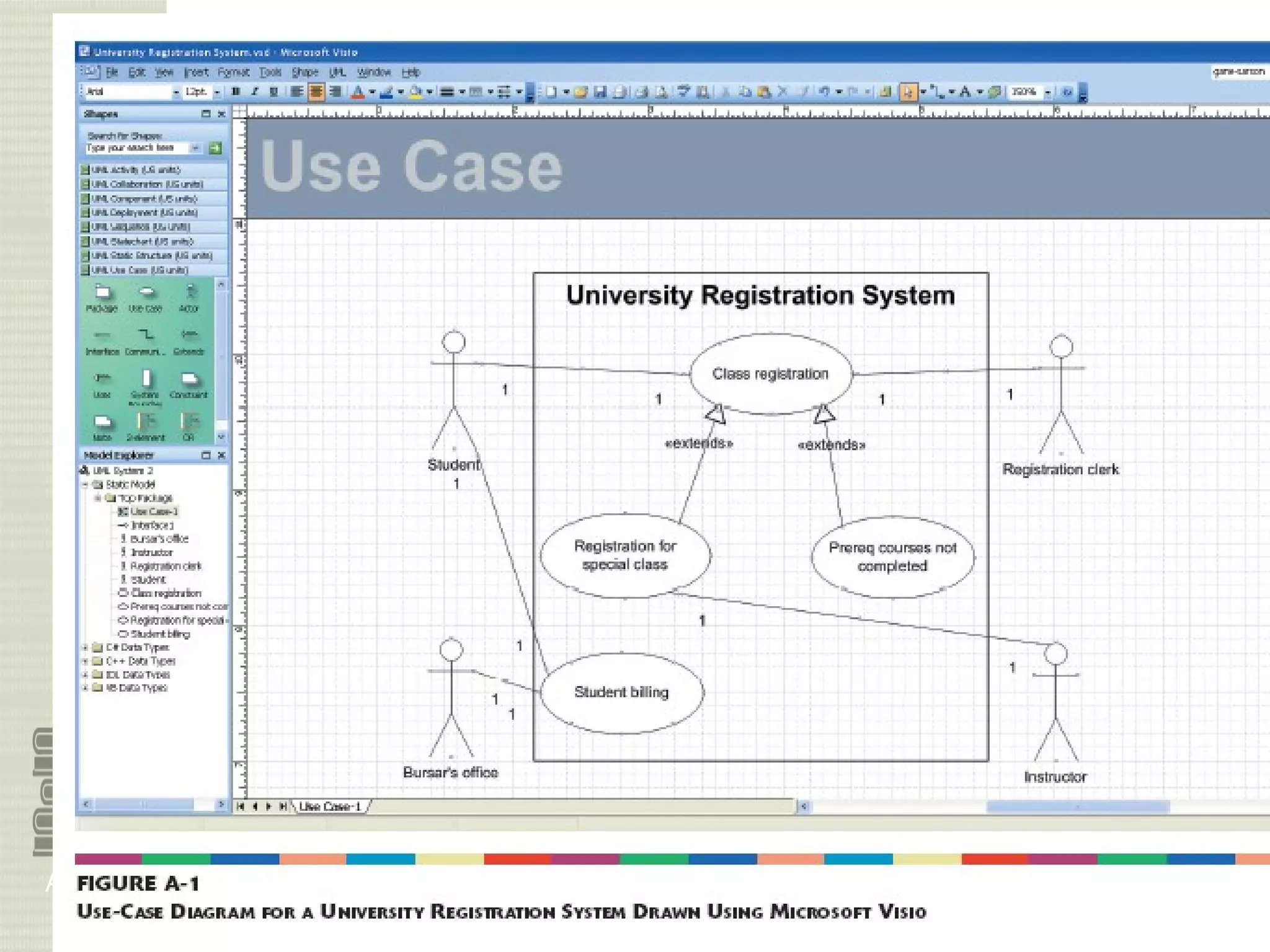
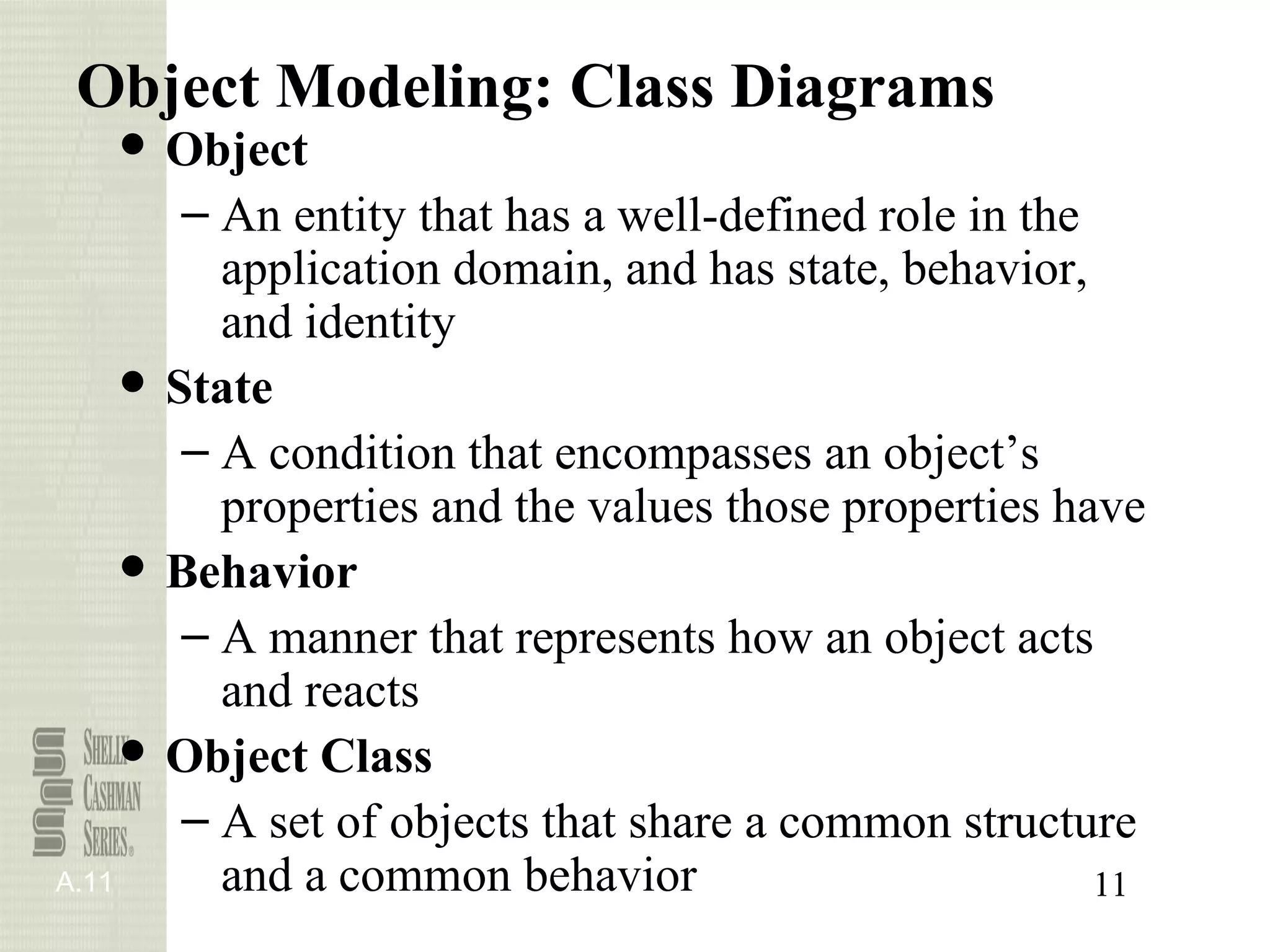


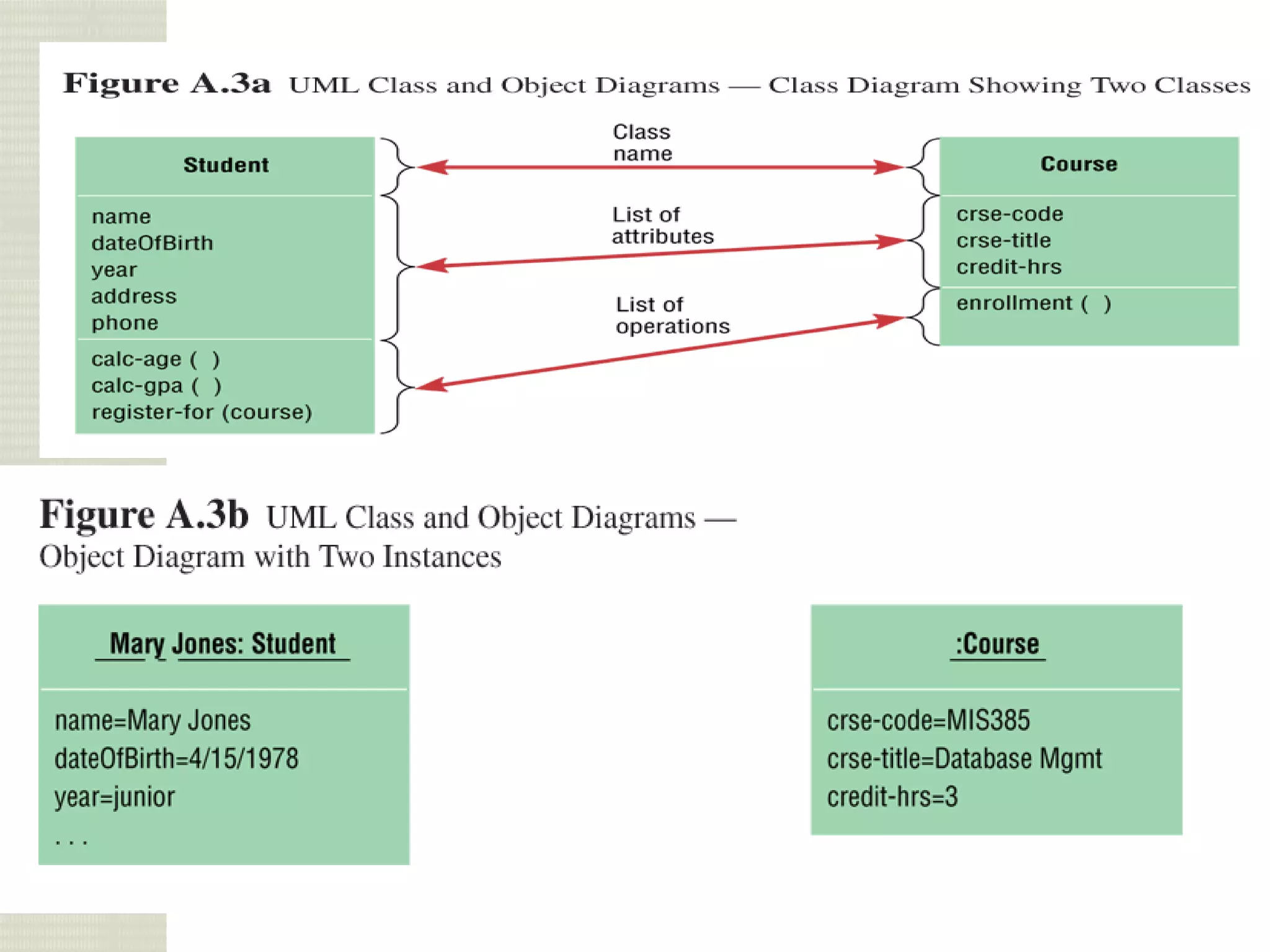


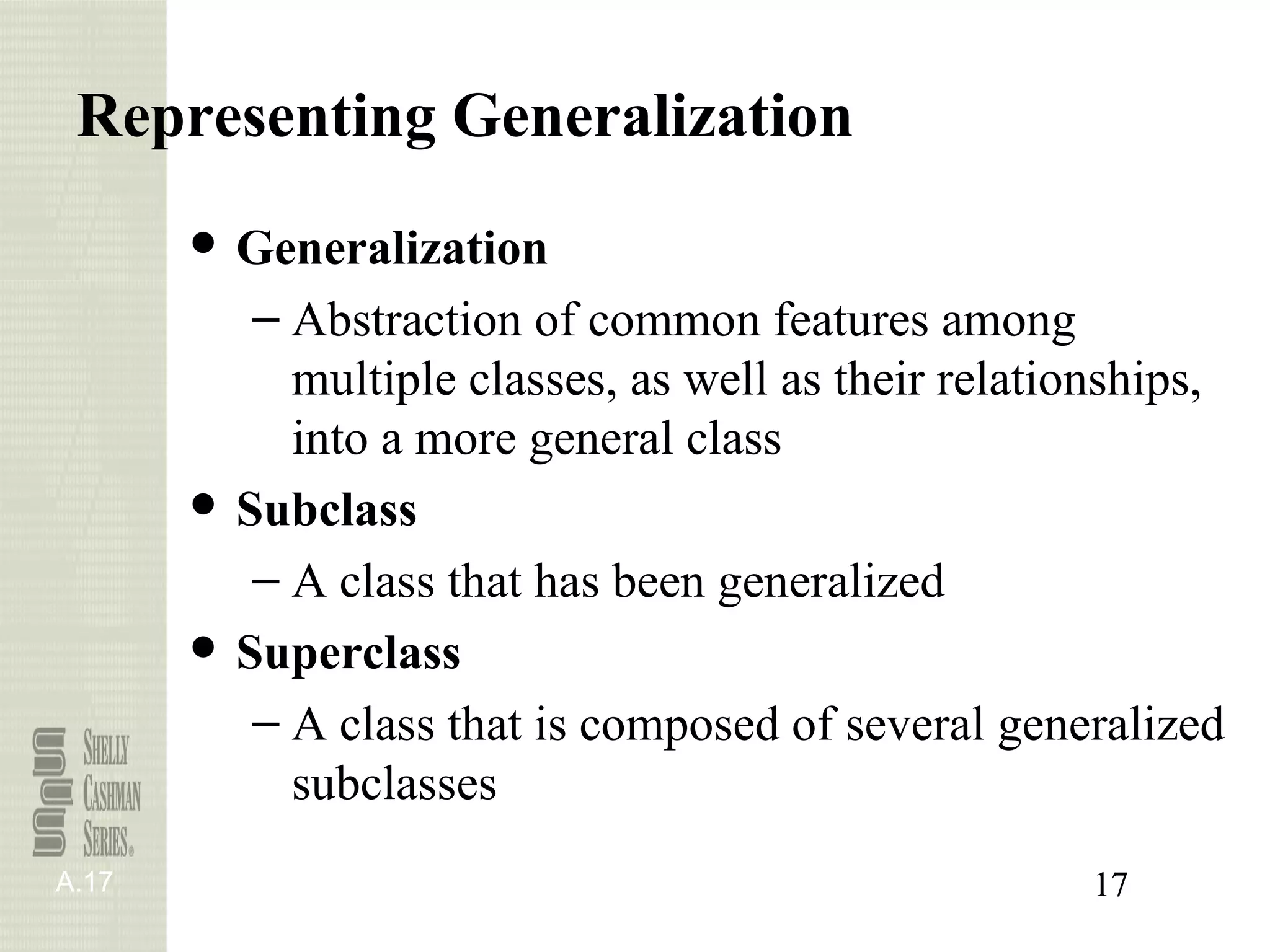


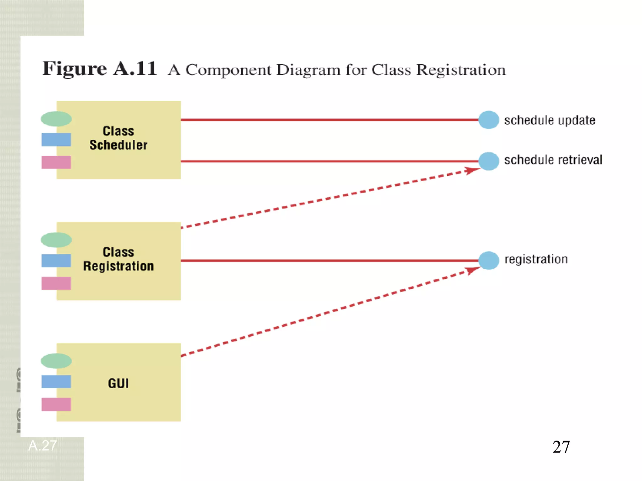


This document provides an overview of object-oriented analysis and design. It defines key terms and concepts in object-oriented modeling like use cases, class diagrams, states, sequences. It describes developing requirements models using use cases and class diagrams. It also explains modeling object behavior through state and sequence diagrams and transitioning analysis models to design.