Objective
At the endof the topic trainee will be
able to understand and explain
various units of the VCS System.
CATC/CNS/Ab-initio/VHF/VCS
System 2
3.
INDEX
Purpose
Introduction
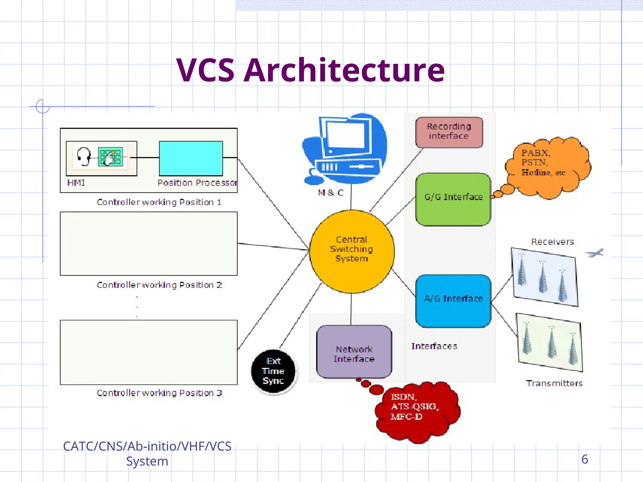
VCS Architecture
SCHMID VCSICS 200/60
VCS Hardware Configuration
Communication Server System
Interface subsystem
Management (Monitoring and Control) system
Controller Position
CATC/CNS/Ab-initio/VHF/VCS System 3
4.
Purpose
Due increase inair traffic, controller get
busy to handle voice communication.
So requirement of such system by which
all the communication can be easily
perform.
To improve performance & Safety.
Any Voice communication can be
performed any controller position.
CATC/CNS/Ab-initio/VHF/VCS
System 4
5.
Introduction
Voice communication systemis a
switching system, which connects the
different controller positions to various
Air-to-ground (A/G) and Ground-to-
ground (G/G) communication systems.
AAI Uses different VCS System.
SCHMID VCS
DRAKE VCS
FREQUENTIS VCS
CATC/CNS/Ab-initio/VHF/VCS
System 5
SCHMID VCS ICS200/60
ICS -Integrated Communications System.
200-Operartor Position /Controller
Position.
60- Time Slot /Analog-Digital
59 oice Data.
01 Digital Data.
Fully digital design.
Fast switching performance for radio and
telephone channels.
CATC/CNS/Ab-initio/VHF/VCS
System
7
8.
Well-developed BITE (Built-inTest
Equipment) possibilities support an
easy maintenance of the system.
Fast online reconfiguration on the
running system.
Three main subsystems:
The server system.
The interface system.
The operator position rings.
SCHMID VCS ICS 200/60
CATC/CNS/Ab-initio/VHF/VCS
System 8
9.
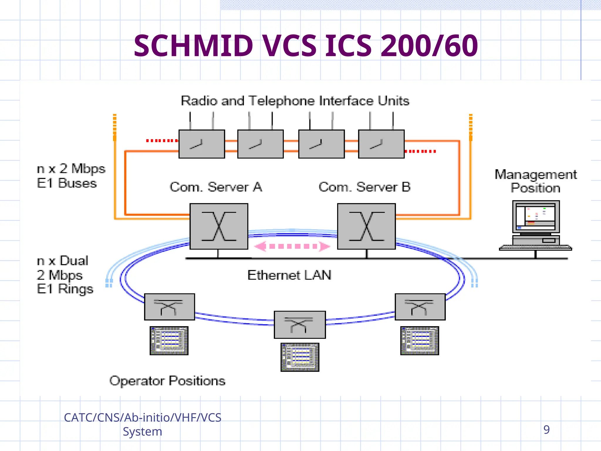
SCHMID VCS ICS200/60
CATC/CNS/Ab-initio/VHF/VCS
System 9
10.
Four main elementsof the system are:-
Communication Server System(CSS).
Interface subsystem.
Monitoring and Control(Management
System).
Controller Work Position
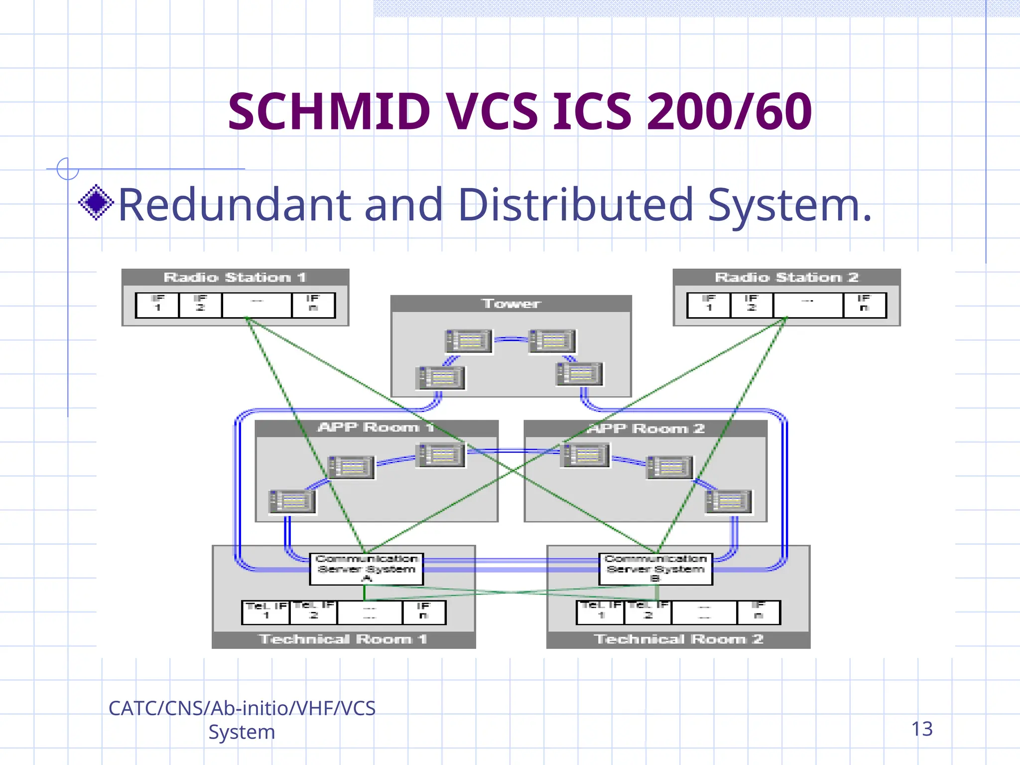
We can connect up to 700 Radio &
Telephone interface.
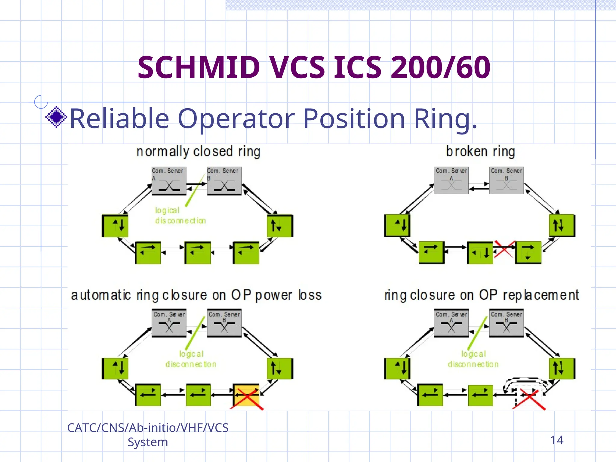
Operator positions are connected to
server in Ring topology manner.
SCHMID VCS ICS 200/60
CATC/CNS/Ab-initio/VHF/VCS
System
10
11.
Bus Topology isused for Interface.
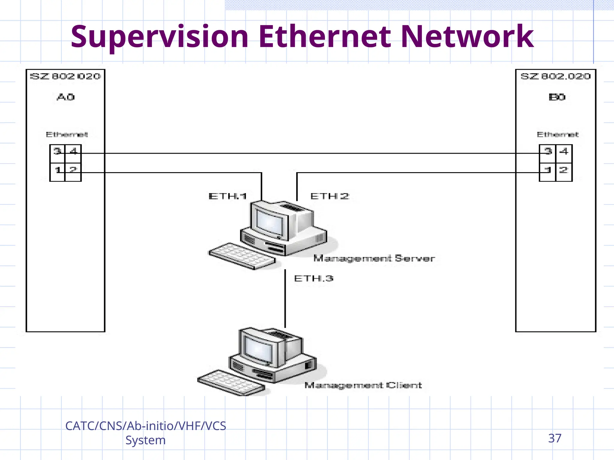
Management PC is connected by
Ethernet LAN.
Four Rings Can be maintained.
In One Ring - 2 E1 Line.
Total E1 Line= 08
One E1 Line=32 channel; Each 64Kbps
One E1 Line Capacity=32*64=2.048Mbps.
SCHMID VCS ICS 200/60
CATC/CNS/Ab-initio/VHF/VCS
System 11
12.
One Ring=64 Channel Slots
0 – reserved for synchronization.
16 – reserved for real time signaling (PTT &
Squelch).
One is reserved for ISDN & QSIG.
ISDN is use for Management purpose.
ATS-QSIG used for networking of Different VCS
System.
In one ring 50 operator position can
connect.
SCHMID VCS ICS 200/60
CATC/CNS/Ab-initio/VHF/VCS
System 12
VCS Hardware Configuration
Elementsof SCHMID VCS are :-
Communication Server System(CSS).
Interface subsystem.
Management (Monitoring and Control)
system.
Controller Work Position
CATC/CNS/Ab-initio/VHF/VCS
System 15
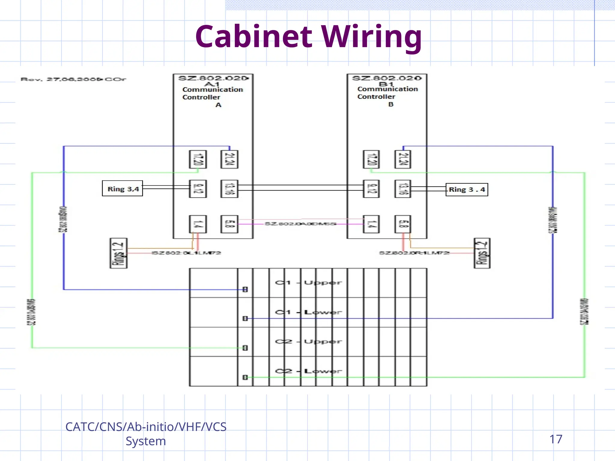
Communication Server System
(CSS)
Thecommunication server system
modules are accommodated in server
subracks of ICS 200/60 cabinets.
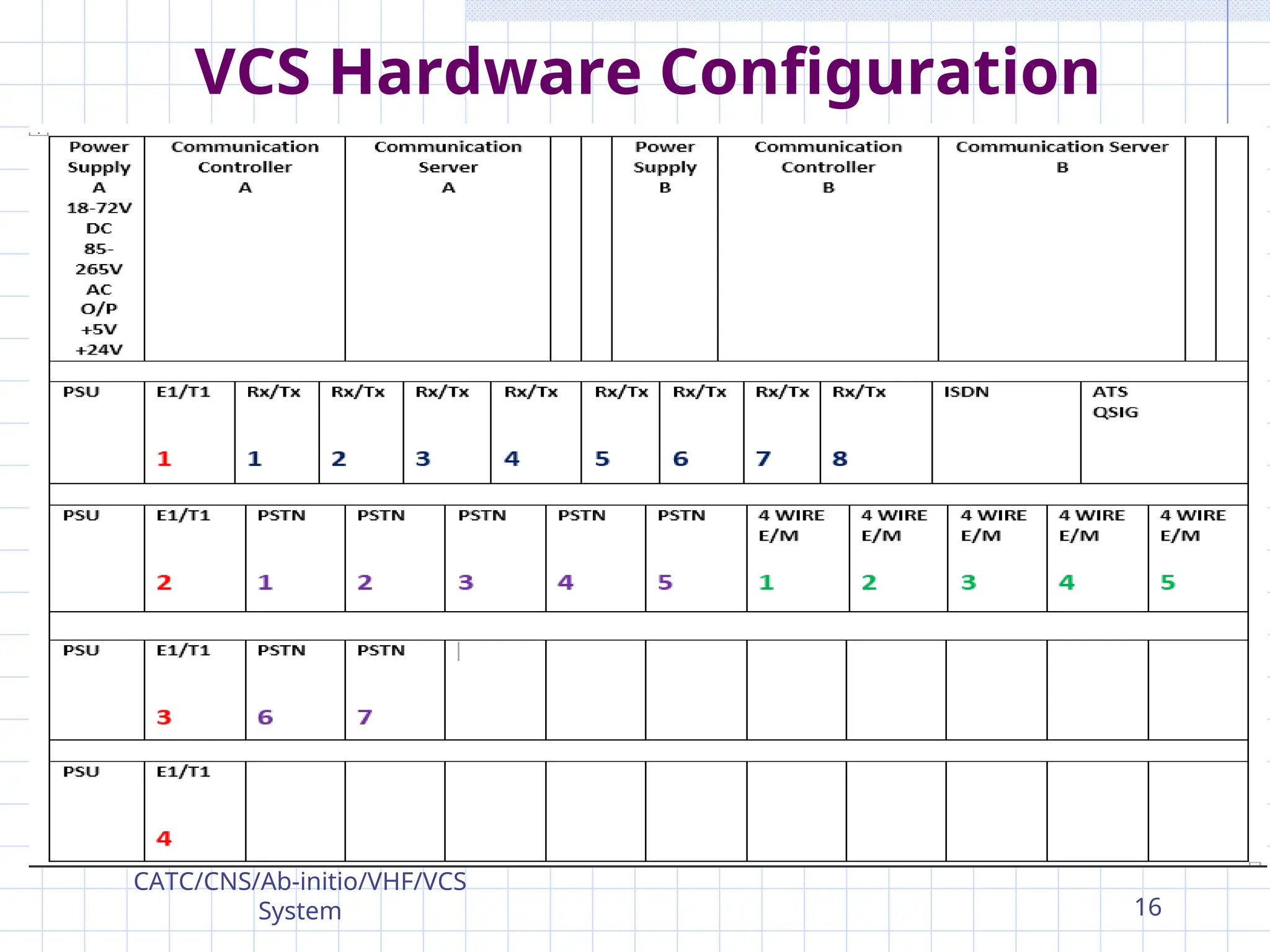
Main Modules are:-
2 Communication Controller (A & B).
2 Communication Server (A & B)
2 Server Subrack Power Supplies
CATC/CNS/Ab-initio/VHF/VCS
System 19
20.
Communication Server System
(CSS)
CommunicationController (SZ.802.010)-
Is responsible for all operator-controlled
and all signal based switching decisions
(ATS, radio-main/standby selection) of the
Communication Server Modules.
The communication controller has the
following main features:
Control of up to 8 communication servers
Start up without management control
Disk- and fan-less operation
CATC/CNS/Ab-initio/VHF/VCS
System 20
21.
Communication Server System
(CSS)
CommunicationController (SZ.802.010)-
The communication controller has the
following main features:
Operation with second redundant
communication controller.
Hot swappable.
Multiple Ethernet interfaces for
management access.
SNMPv3 management access.
CATC/CNS/Ab-initio/VHF/VCS
System 21
22.
Communication Server System
(CSS)
CommunicationServer (SZ.802.020)-
Has the following main features:
6 x 4 x E1 on front panel
2x4096 Voice slots on Backplane through
2xH.110 (32 x 8 Mbps)
Drop and insert of voice data from and into
respectively time slots.
Fast switching capability
CATC/CNS/Ab-initio/VHF/VCS
System 22
23.
Communication Server System
(CSS)
Executes all tasks and switching commands
assigned through the Communication
Controller.
Executes all real-time tasks
Free assignment of E1 connections to
operator position rings and interface
busses.
Free assignment of the bandwidth of
operator position rings (1 to 4 E1) and
interface busses.
CATC/CNS/Ab-initio/VHF/VCS
System 23
24.
Communication Server System
(CSS)
Dynamic assignment of the HDLC-
Bandwidth in operator position rings and
interface buses.
Start up without management control
Supports manually started self tests
Replacement without pre-configuration
Disk- and fan-less operation
Hot swappable
CATC/CNS/Ab-initio/VHF/VCS
System 24
25.
Communication Server System
(CSS)
PowerSupply (SZ.801.010) -
The 200 W power supply module.
Supports DC power input 18 to 72 V.
Or AC input the range of 85 to 265 VAC.
The output voltages are +5 VDC, +24 VDC.
The in/outputs are galvanic separated.
The status of the input and output voltages are
shown by 4 LEDs on the front panel and is
available on the communication controller.
Two identical power supplies are used for
redundancy.
CATC/CNS/Ab-initio/VHF/VCS
System
25
26.
Communication Server System
(CSS)
PowerSupply (SZ.801.010) –
Main features of the power module are:
Wide AC and DC power input range.
Redundant AC and DC input.
Possibility of two redundant power modules
with load sharing.
Hot-swap capability.
Protection of in- and outputs .
Possibility of extensive supervision of the
module. by management .
CATC/CNS/Ab-initio/VHF/VCS
System 26
27.
Communication Server System
(CSS)
PowerSupply (SZ.801.010) –
Main features of the power module are:
Basic information for error source
determination.
Detection of primary supply failure.
Readout of secondary voltages and currents .
Readout of temperature.
CATC/CNS/Ab-initio/VHF/VCS
System 27
28.
Interface subsystem
Accommodate thefollowing interface
modules :-
8 Radio 4-w E&M interface modules for
access to 8 radio lines (4 freq. in main/st.-
by configuration)
7 Universal Quad 2-w interface module.
1 ATS-QSIG interface modules for access to
2x QSIG channels
1 ISDN interface modules.
CATC/CNS/Ab-initio/VHF/VCS
System 28
29.
Interface subsystem
5E&M interface modules
4 E1/T1 System internal interfaces
4 Interface subrack power supplies
Interface subsystem modules as follws:-
Universal quad E1/T1 Interface Module
(SZ.814.010V1).
Quad 2-wire Interface Module
(SZ.812.010V1).
Radio interface module (SZ.693.030.V11) .
CATC/CNS/Ab-initio/VHF/VCS
System 29
30.
Interface subsystem
Universal quadE1/T1 Interface
Module (SZ.814.010V1):-
Operating Modes
Interface Subrack Controller Mode Access
between the comm. Server subsystems and
the backplane of interface subracks.
ICS-ICS Networking Mode Interconnection
between several ICS 200/60 systems
offering telephone, radio and control
communication.
CATC/CNS/Ab-initio/VHF/VCS
System 30
31.
Interface subsystem
Quad 2-wireInterface Module
(SZ.812.010V1):-
Have BORSCHT functions:
B—battery feed
O—overvoltage protection
R—ringing
S—signaling
C—coding (analog-to-digital conversion and
digital-to-analog conversion)
H—hybrid (two- to four-wire conversion)
T—test
CATC/CNS/Ab-initio/VHF/VCS
System
31
Interface subsystem
SCHMID VCSline interfaces there are 4
legal recording outputs which can
individually export the following voice
slots:
Incoming voice
Outgoing voice
Summary of incoming and outgoing voice
CATC/CNS/Ab-initio/VHF/VCS
System 33
34.
Interface subsystem
Radio interfacemodule
(SZ.693.030.V11):-
To provide the following interfaces and
related functions for 1 radio channel:
One digital voice input is converted to an
analogue output (600 Ohms).
One analogue input (600 Ohms) is converted
to a digital voice output .
Control the radio transceiver via a V.24/28
serial interface.
CATC/CNS/Ab-initio/VHF/VCS
System 34
35.
Interface subsystem
Radio interfacemodule
(SZ.693.030.V11):-
The module provides the following
external Interfaces:
A 4-wire Tx/Rx line interface circuit.
E(ar) input and M(outh) output for Squelch and
Push To Talk signaling.
One legal recording output as sum of input
and output signal.
V.24/28 serial interface.
CATC/CNS/Ab-initio/VHF/VCS
System
35
36.
Management (Monitoring and
Control)system
The management system bases on PC
system.
Offers the possibility to configure,
monitor and supervise the ICS 200/60
system.
It consists of:
2 Management Server PC with 17" TFT
colour flat screen
2 Laser Printer
CATC/CNS/Ab-initio/VHF/VCS
System 36
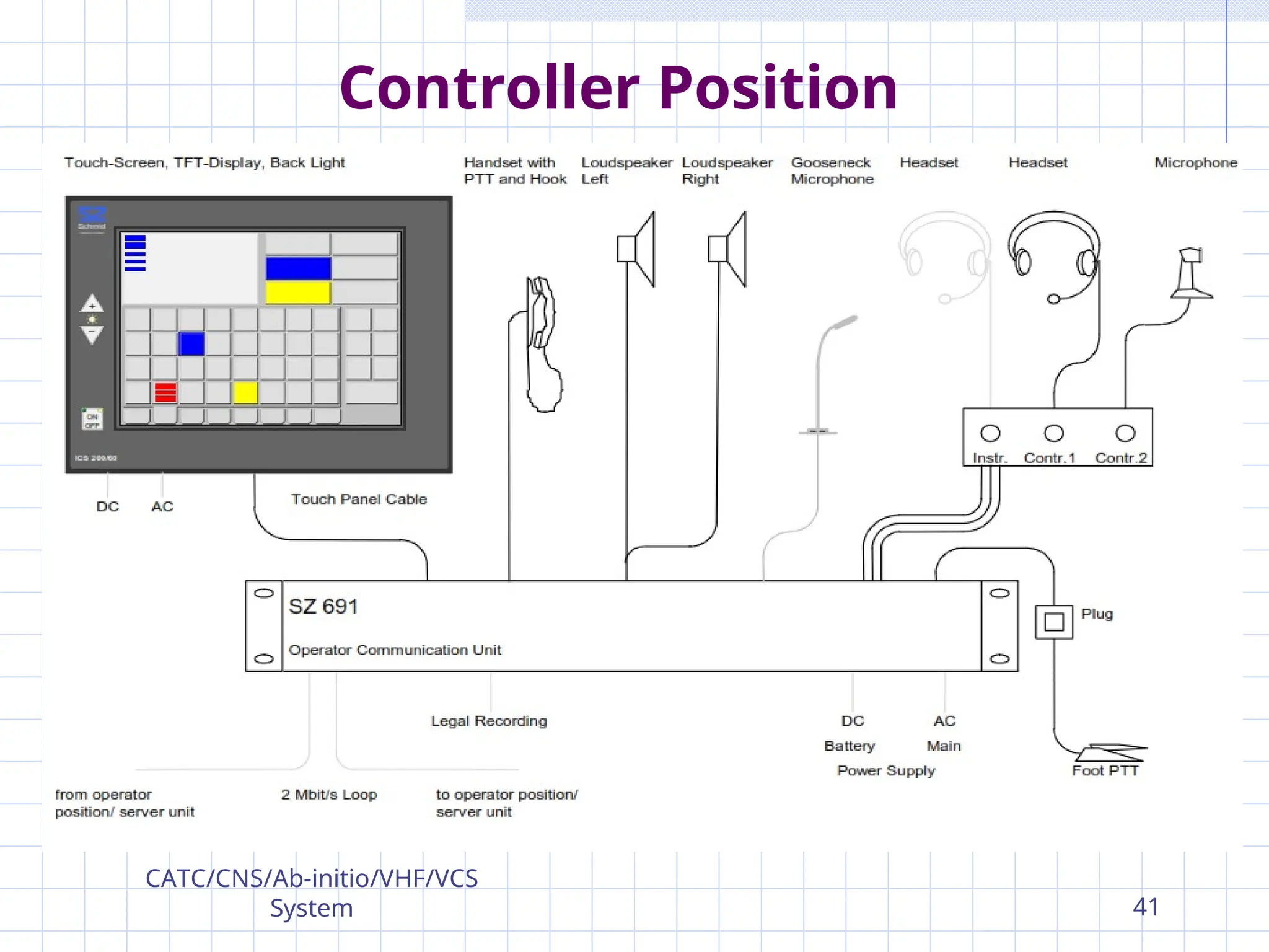
Controller Position
The OperatorCommunication Unit (OCU)
is the central part of the operator
position.
OCU provides the digital and analogue
signal processing for any
communications taking place at the
position.
Operator position serves as
communications tool to a controller, an
assistant or a supervisor.
CATC/CNS/Ab-initio/VHF/VCS
System 38
39.
Controller Position
OCU buildsthe interface between the
audio and display devices and VCS.
It is responsible for the following tasks:
Digital communications with the server
system
Voice channel management based on the
system configuration and operator inputs
Distribution of audio signals to the
handset, headsets and speakers
CATC/CNS/Ab-initio/VHF/VCS
System 39
40.
Controller Position
OCU isresponsible for the following tasks:
Reception of audio signals from the
handset and the microphones.
Display of radio-, phone and general
system states on a VGA or LCD screen.
Processing of the commands such as
on/off hook, push to talk, dial or general
control commands.
CATC/CNS/Ab-initio/VHF/VCS
System 40
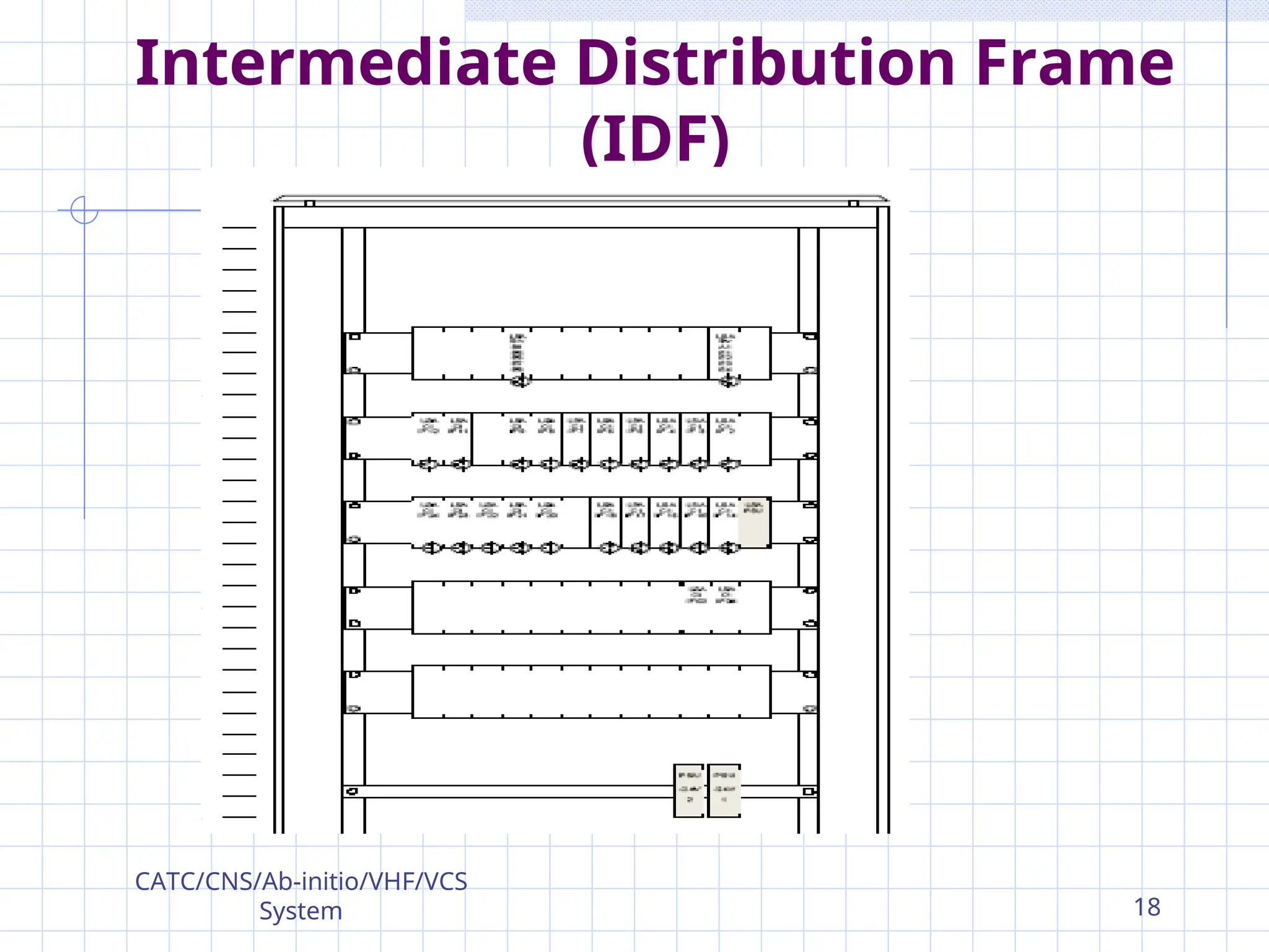
Intermediate Distribution Frame
(IDF)
IDFis built up with LSA (Krone) strips.
Mounted at the rear of ICS 200/60
cabinets directly seen & accessible
from rear side.
The IDF used as interconnection facility
for
the operator positions and the telephon
e and radio interfaces.
CATC/CNS/Ab-initio/VHF/VCS
System 42
43.
Summary
Purpose
VCS Architecture
SCHMID VCSHardware Configuration
Communication Server System & Power Supply
Interface subsystem
E1/T1,Quad 2 wire, Radio Interface
Management, Monitoring and Control system
Controller Position
Intermediate Distribution Frame
CATC/CNS/Ab-initio/VHF/VCS
System 43