Downloaded 441 times
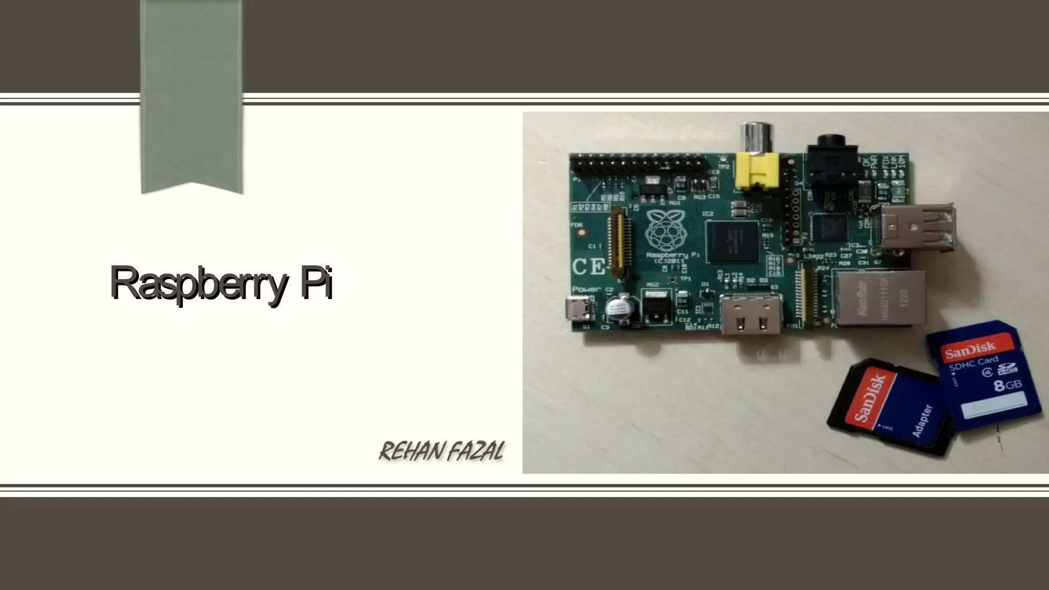
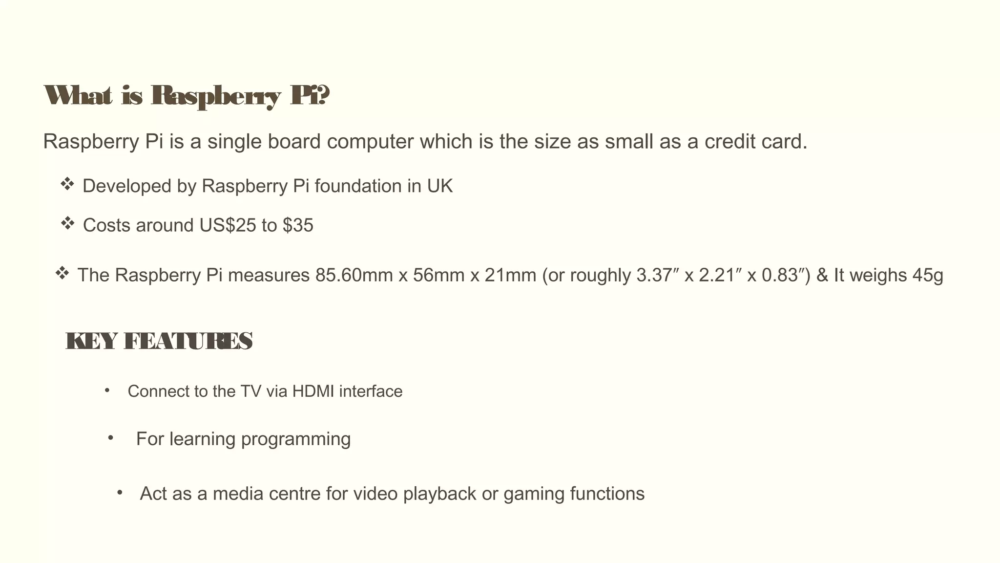
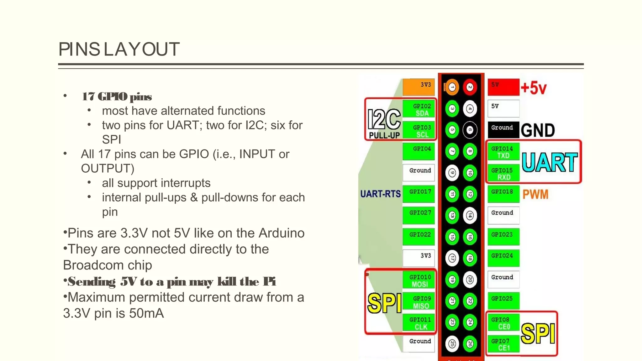

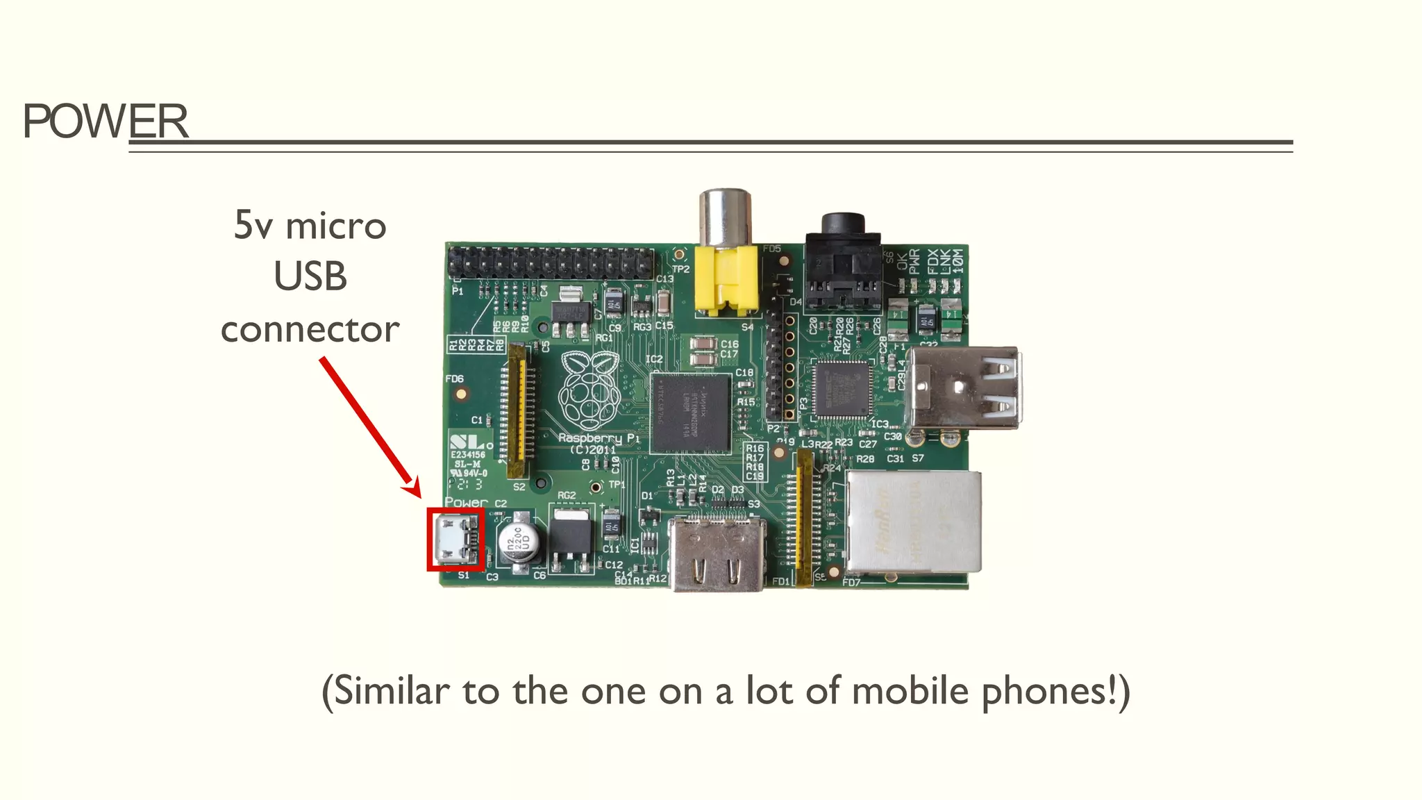
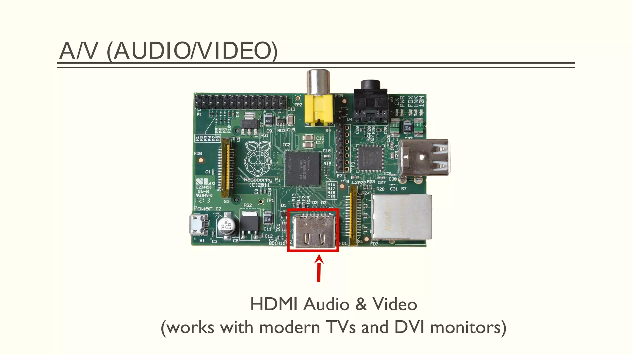
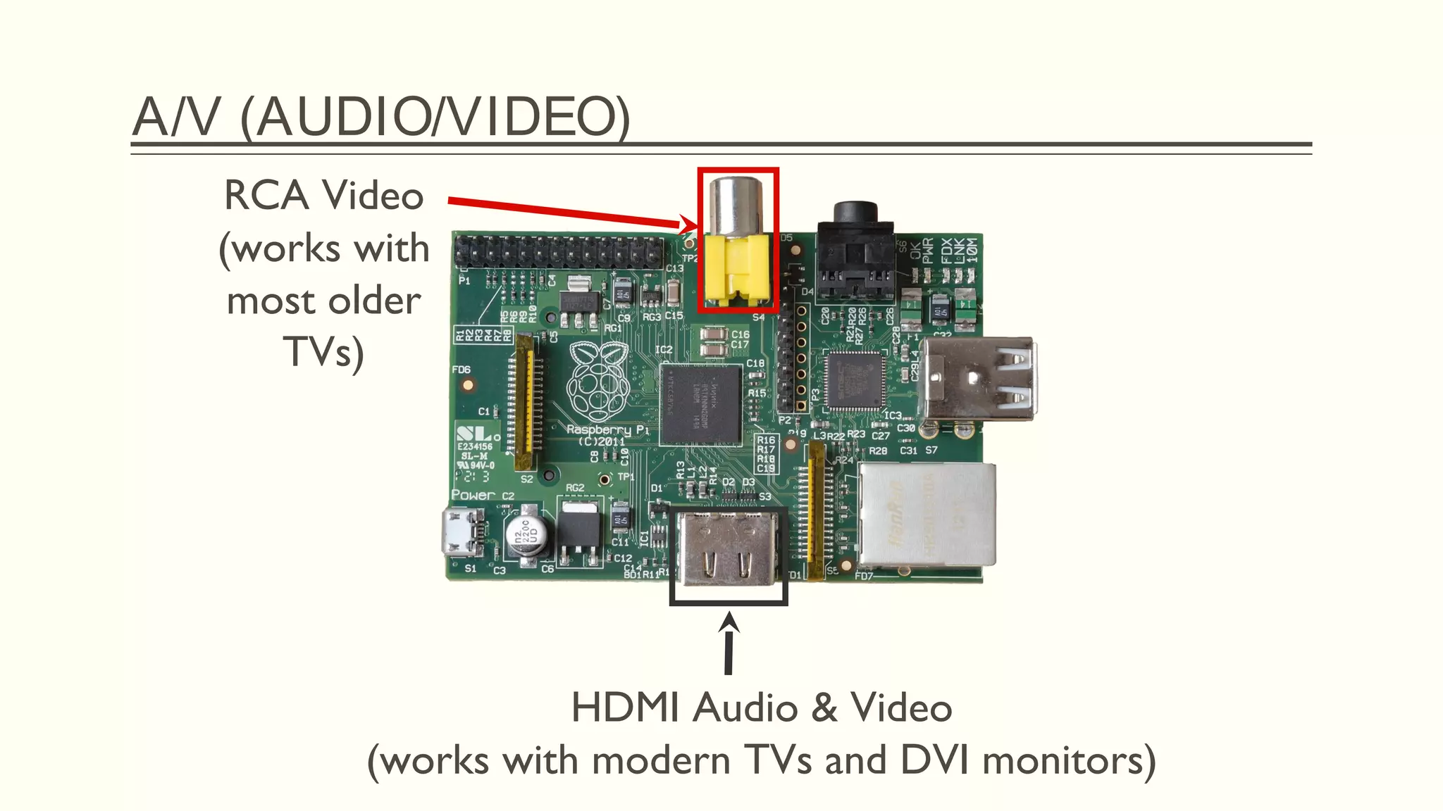
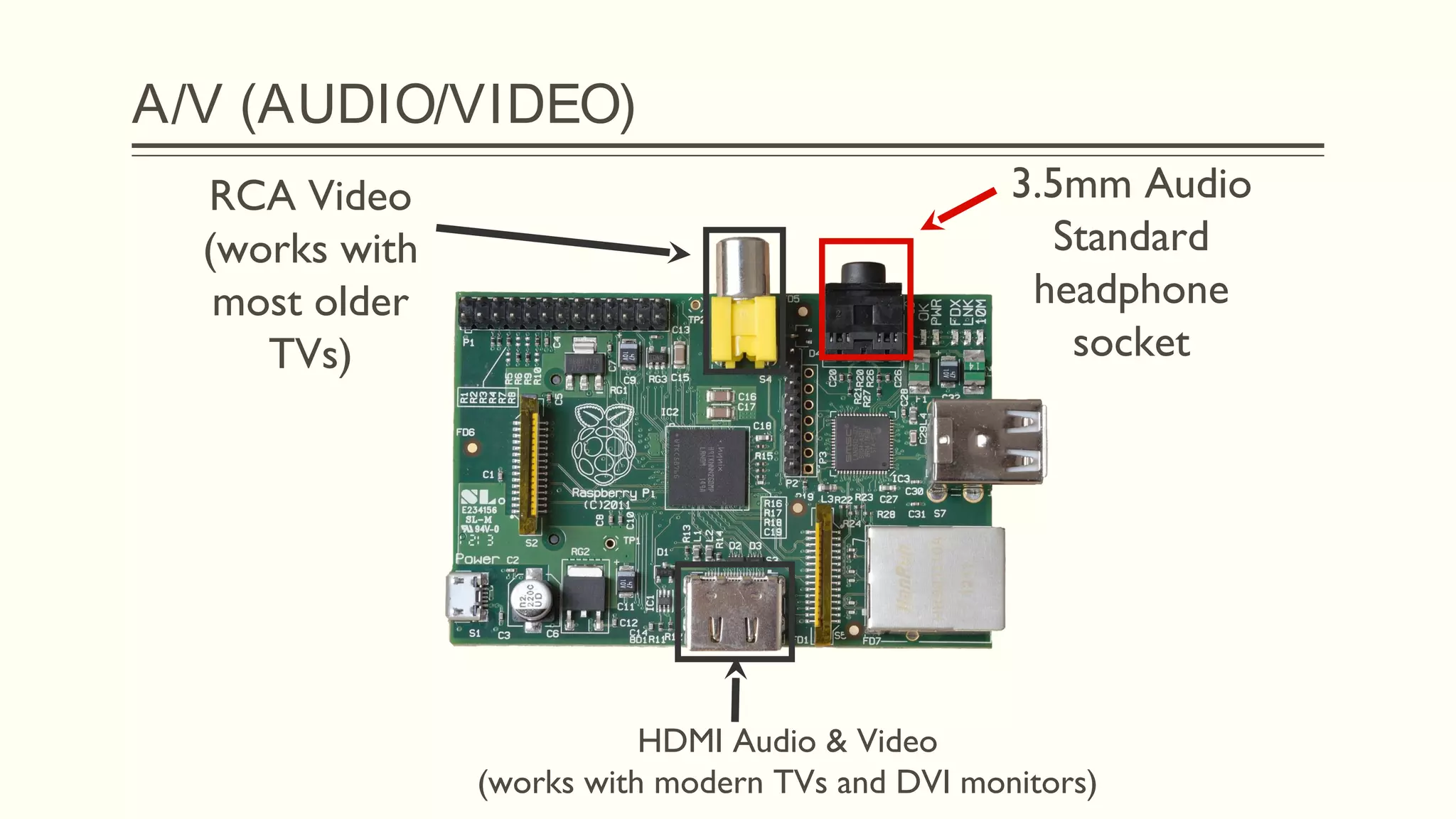
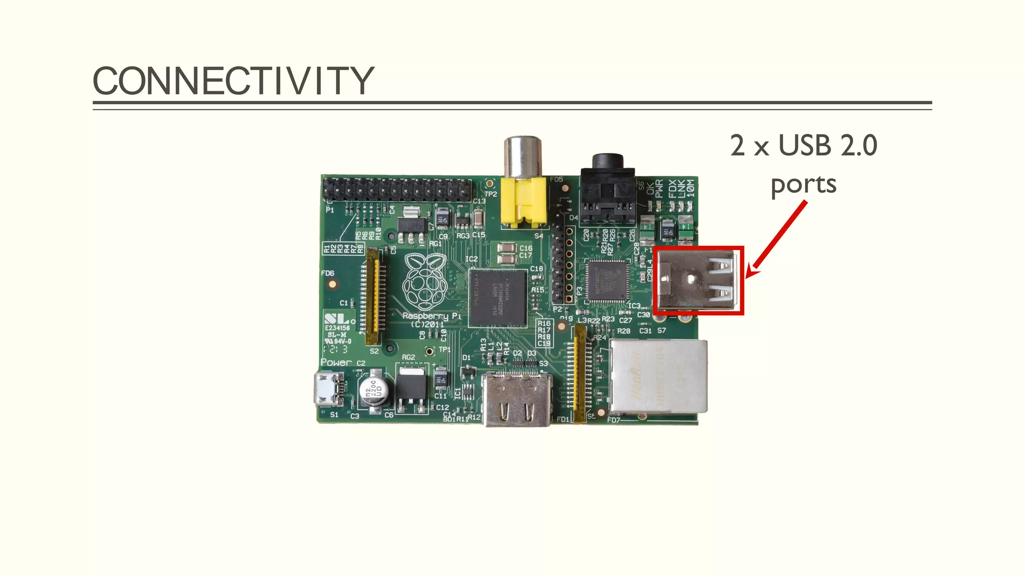
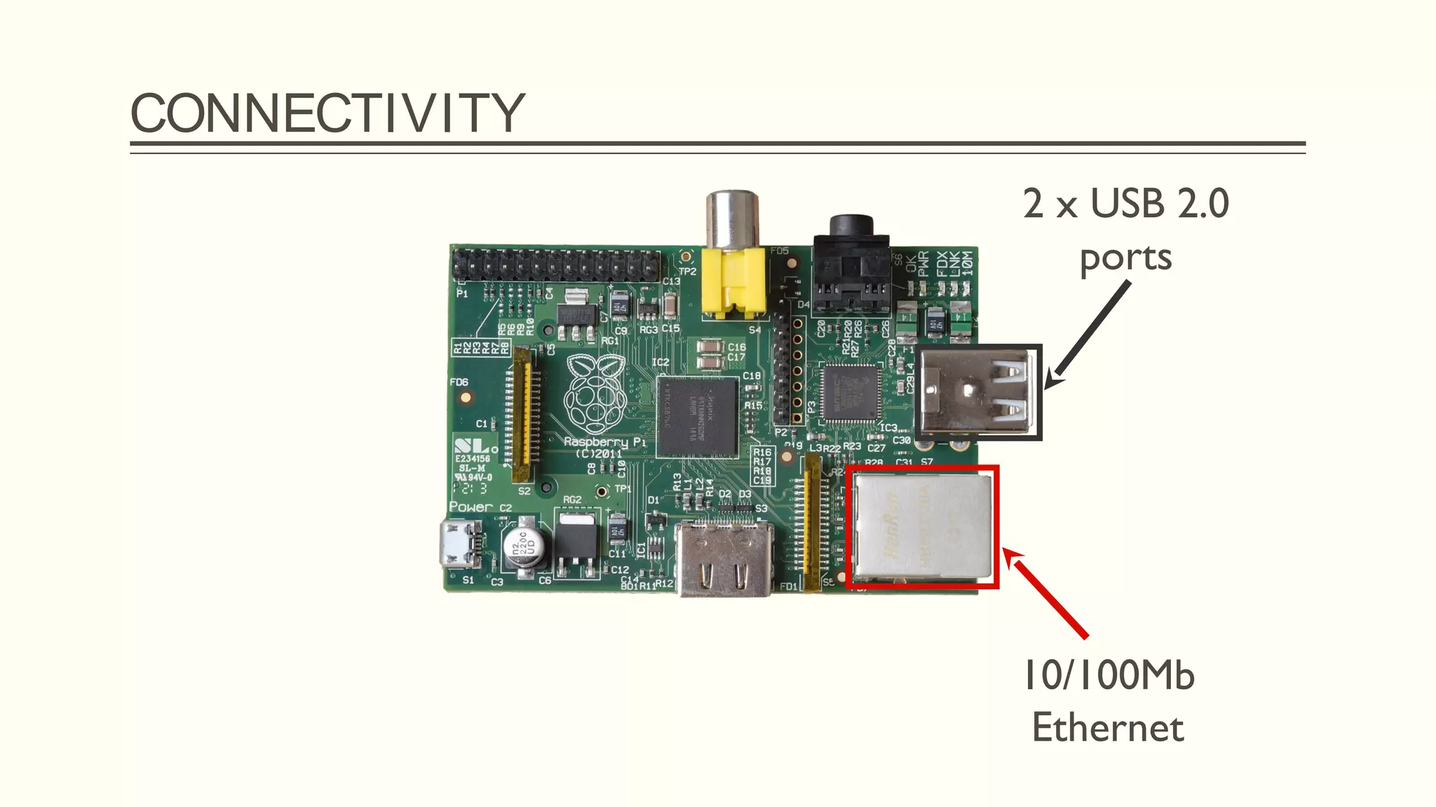
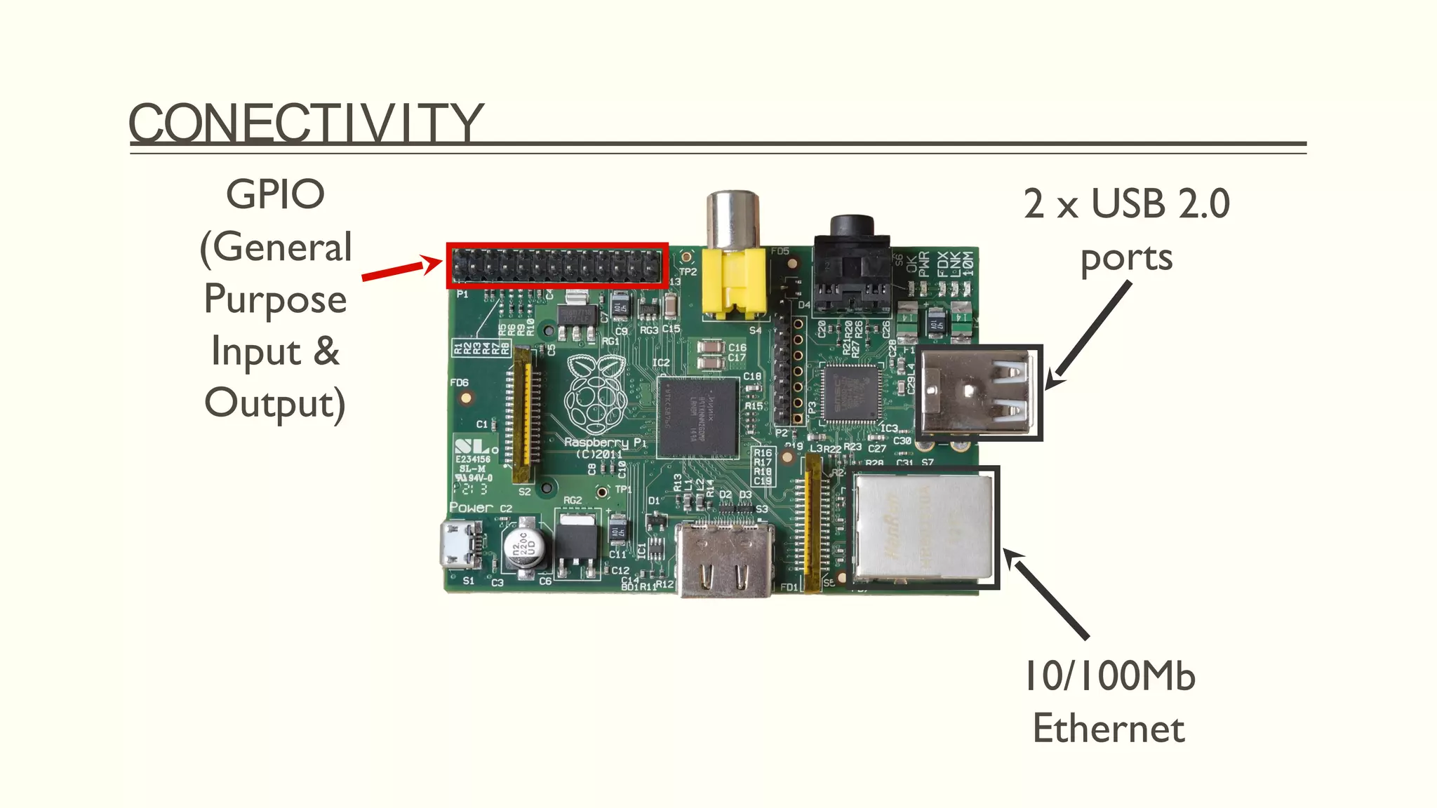
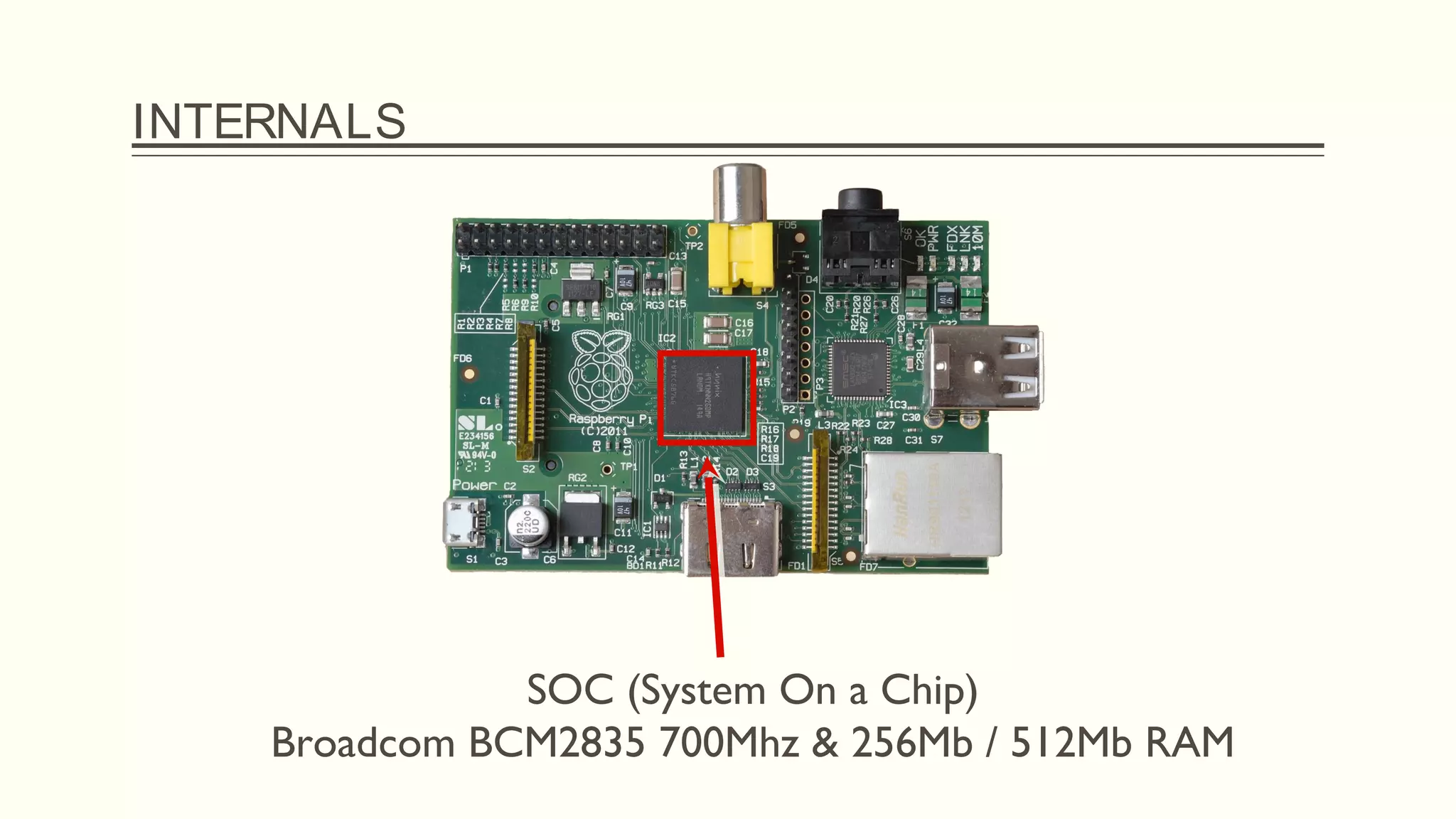
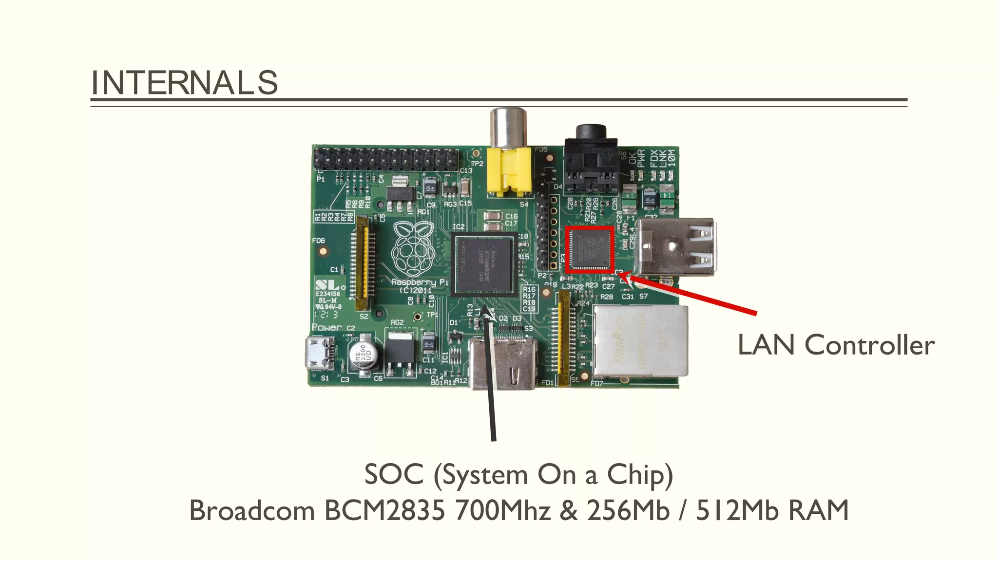
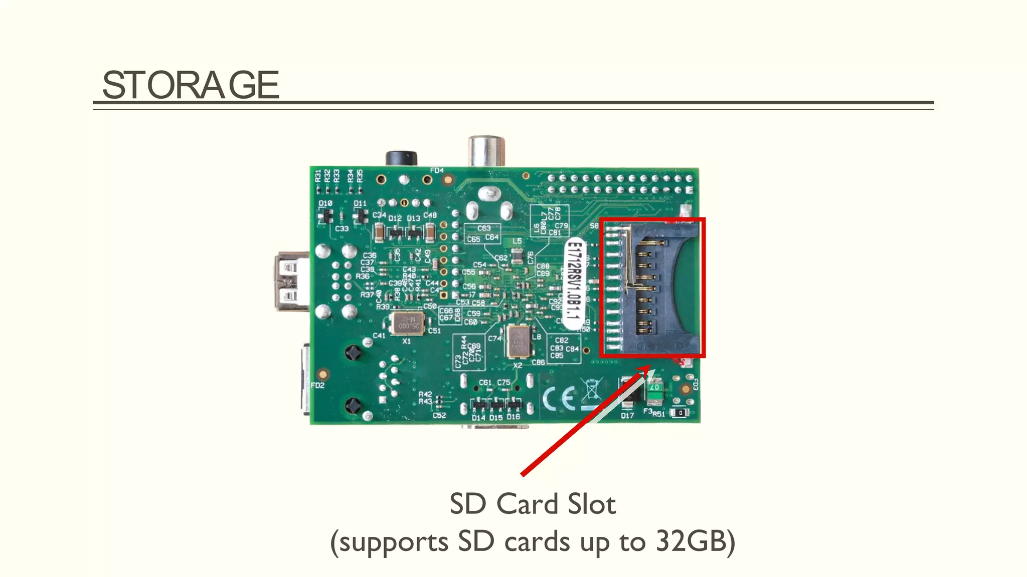


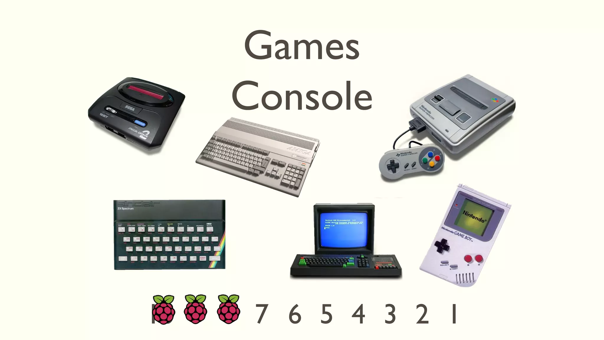


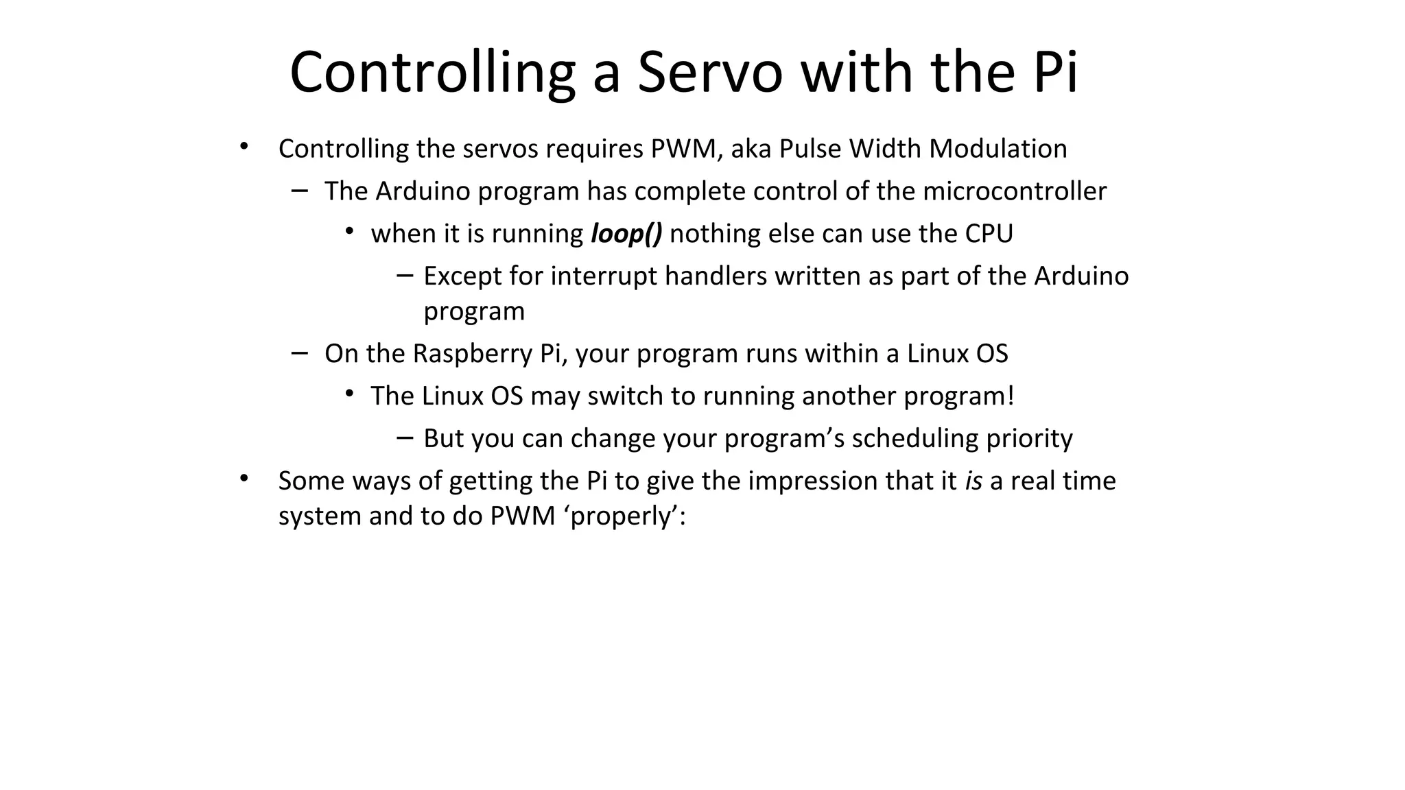
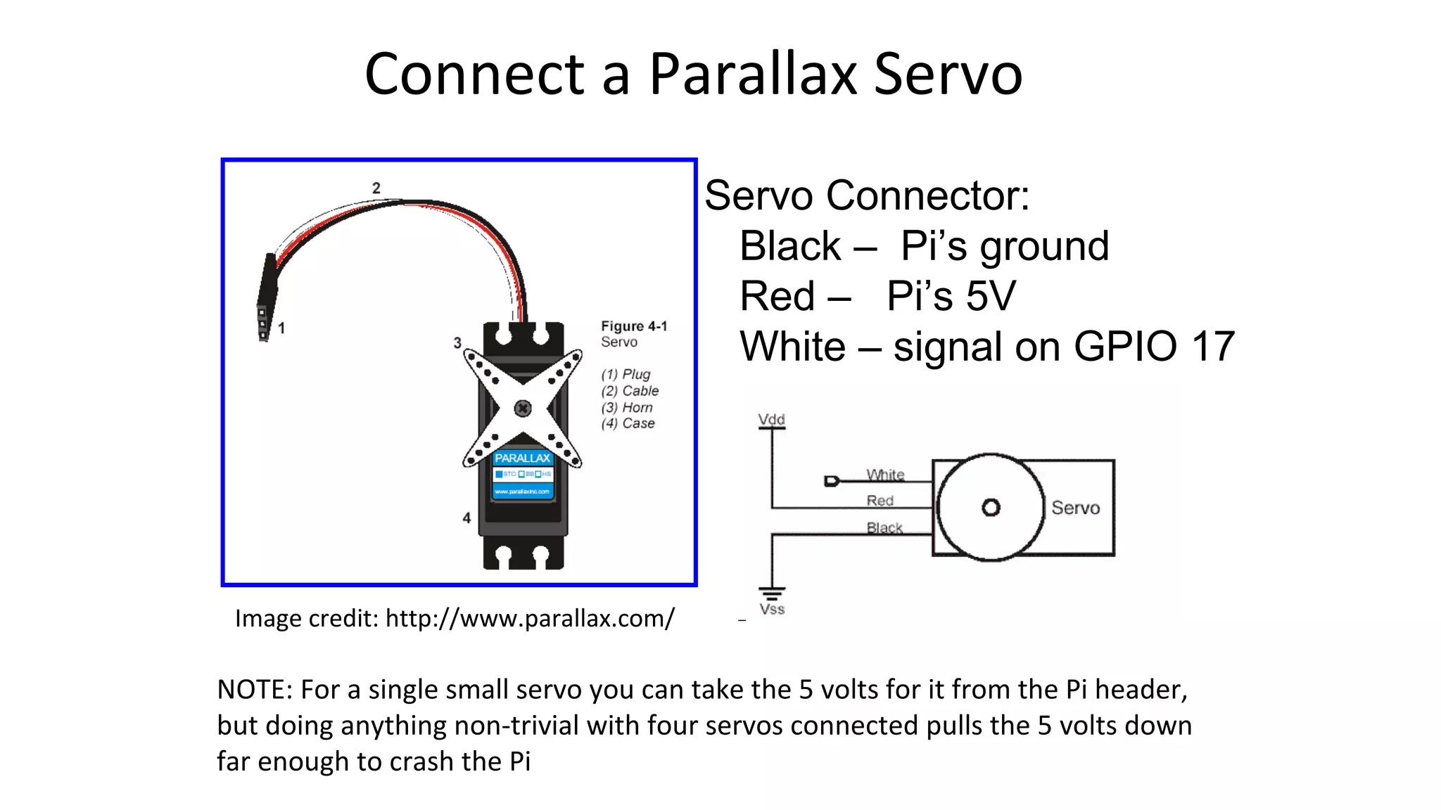
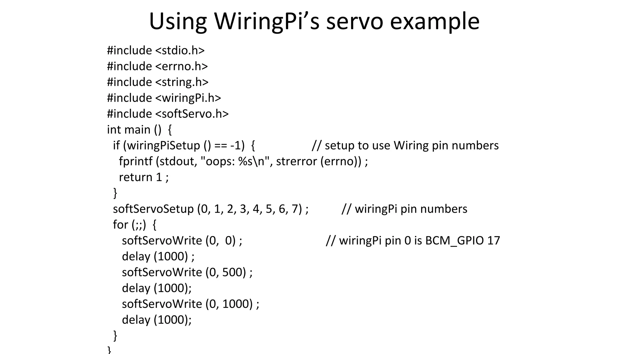
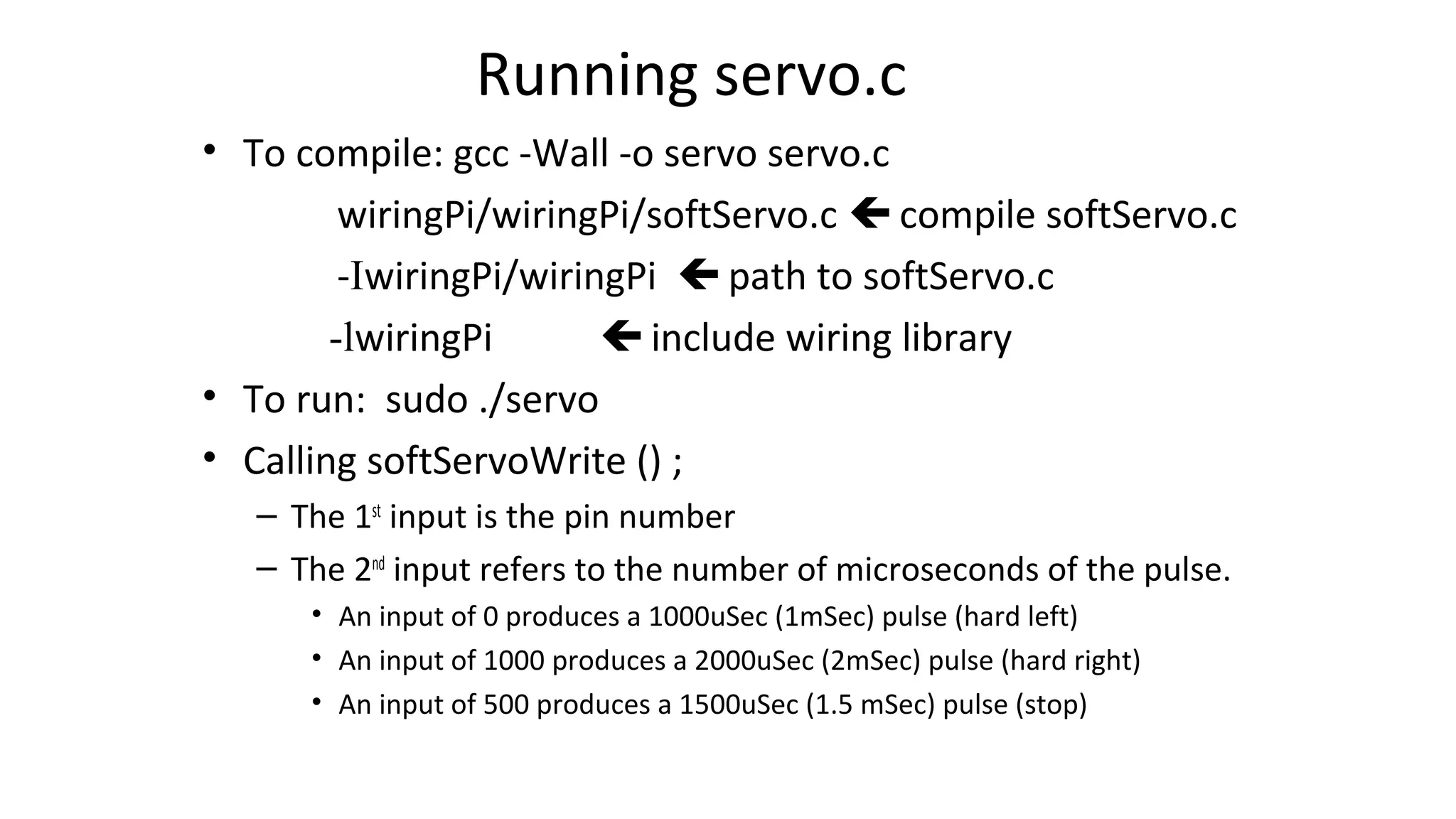


Raspberry Pi is a single board computer that is about the size of a credit card. It has various ports and connections that allow it to be used for many purposes like media center, office tasks, programming, and more. It uses Linux operating systems and can control physical devices like servos through its GPIO pins using Pulse Width Modulation. The document describes connecting a servo to the Raspberry Pi GPIO pin and using the WiringPi library to send PWM signals to control the servo position.