UNIT IV: IoTPhysical Devices & Endpoints
UNIT IV
IoT Physical Devices & Endpoints: what is an IoT Device: Basic building blocks of an IoT
device, Introduction to Raspberry: about the Board, Linux on Raspberry Pi, Raspberry
Pi Interfaces (serial, SPI, I2C), Programming Raspberry Pi with Python: Controlling LED,
integration of LED and Switch, interfacing an Ultrasonic Sensor, PIR sensor, DHT22
sensor, Pi camera.
3.
What is anIoT Device?
Definition:
•Anything that has a sensor attached to it and can transmit data from one
object to another or to people with the help of internet is known as an IoT
device.
OR
•IoT Device Integrates with sensors, actuators, gadgets, appliances, or
machines, that are programmed for certain applications and can transmit
data over the internet or other networks.
4.
Building Blocks ofan IoT Device
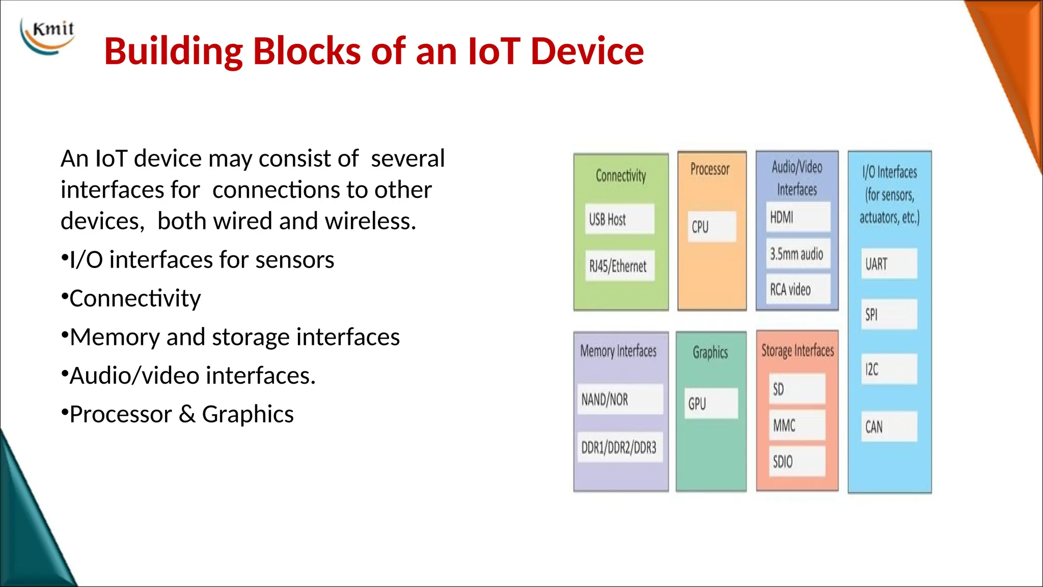
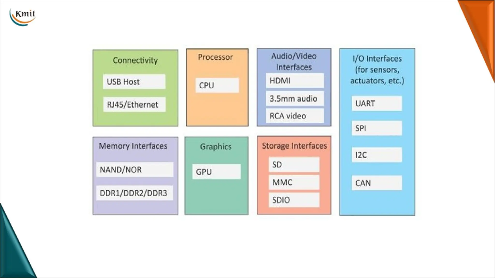
An IoT device may consist of several
interfaces for connections to other
devices, both wired and wireless.
•I/O interfaces for sensors
•Connectivity
•Memory and storage interfaces
•Audio/video interfaces.
•Processor & Graphics
6.
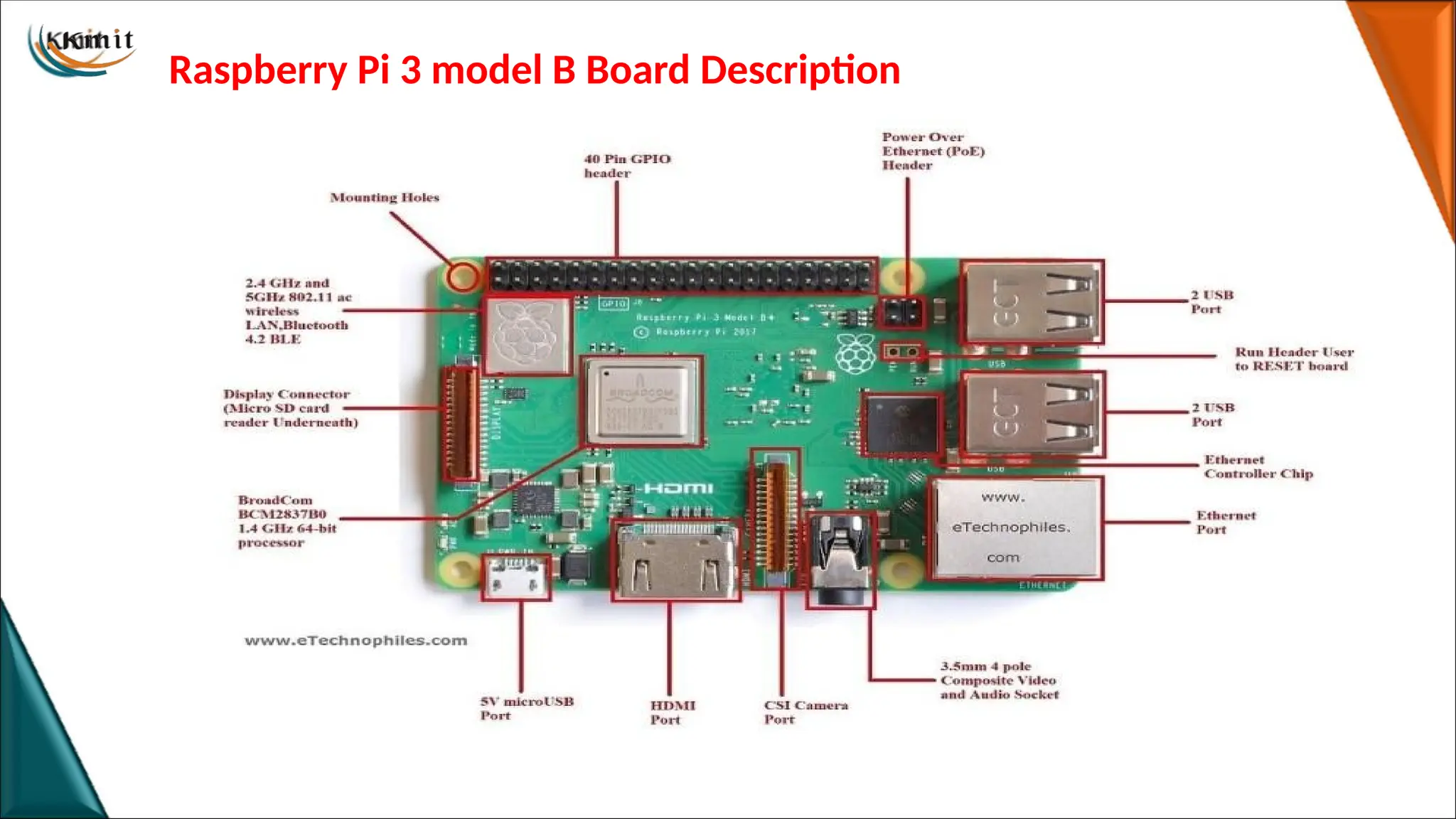
Introduction to RaspberryPi
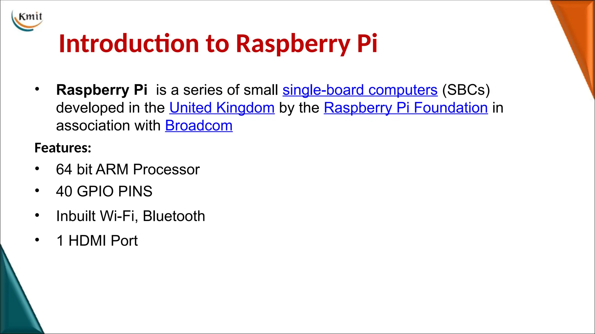
• Raspberry Pi is a series of small single-board computers (SBCs)
developed in the United Kingdom by the Raspberry Pi Foundation in
association with Broadcom
Features:
• 64 bit ARM Processor
• 40 GPIO PINS
• Inbuilt Wi-Fi, Bluetooth
• 1 HDMI Port
7.
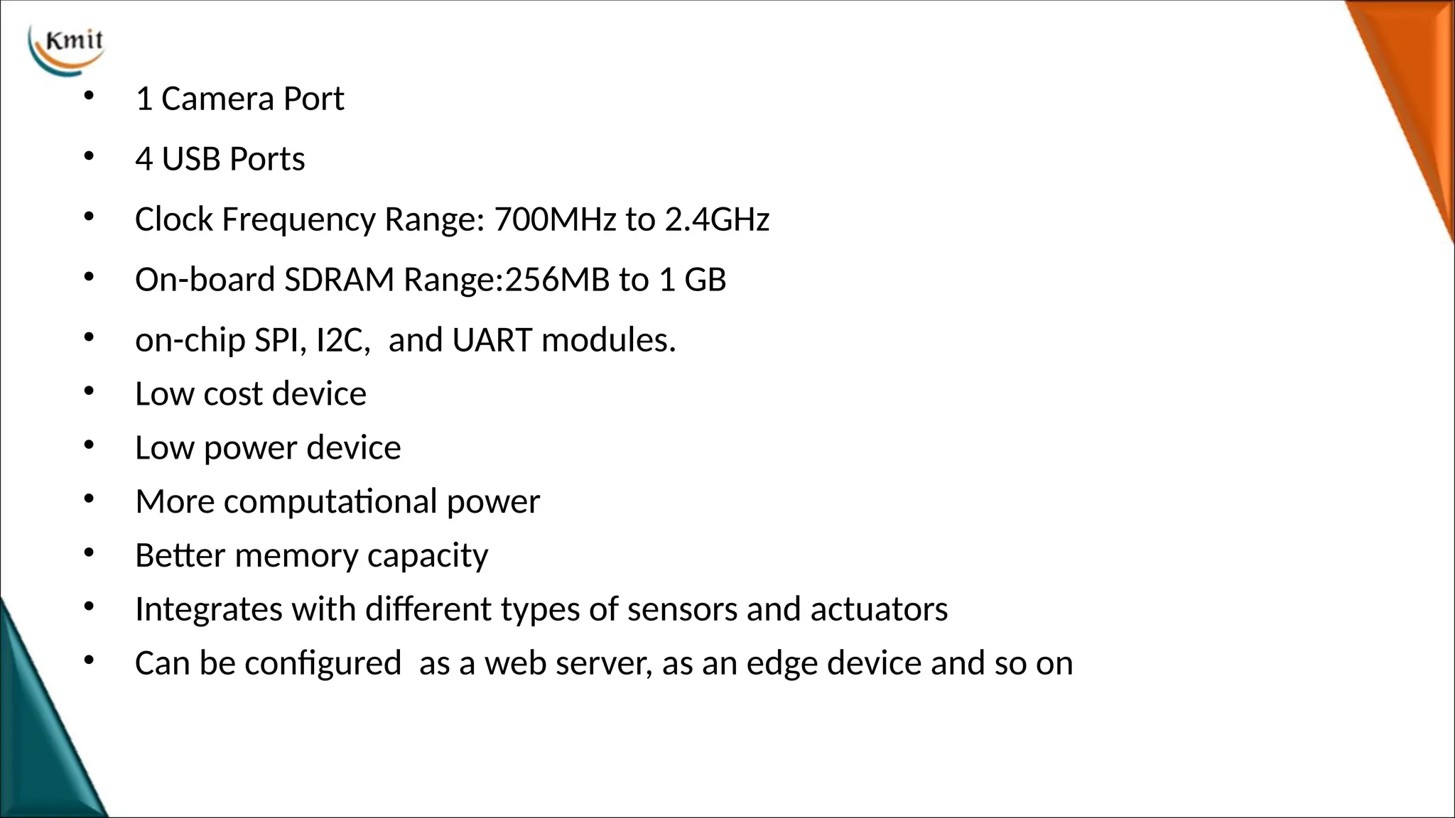
• 1 CameraPort
• 4 USB Ports
• Clock Frequency Range: 700MHz to 2.4GHz
• On-board SDRAM Range:256MB to 1 GB
• on-chip SPI, I2C, and UART modules.
• Low cost device
• Low power device
• More computational power
• Better memory capacity
• Integrates with different types of sensors and actuators
• Can be configured as a web server, as an edge device and so on
• Processor &RAM: 64 bit ARMv7 Broadcom BCM2837 Quad Core Computer running at
1.2GHz.
• USB Ports: Four 2.0 USB ports, provides a current up to 100mA.
• Ethernet Ports: Standard RJ45 Ethernet port to provide Internet connectivity.
• HDMI Output: The HDMI port on Raspberry Pi provides both video and audio output. We
can connect the Raspberry Pi to a monitor using an HDMI cable.
• Composite Video Output: Raspberry Pi comes with a composite video output with an RCA
jack that supports both PAL and NTSC video output. The RCA jack can be used to connect old
televisions that have an RCA input only.
• Audio Output: 3.5 mm audio output jack.
Provides audio output to old televisions along with the RCA jack for video.
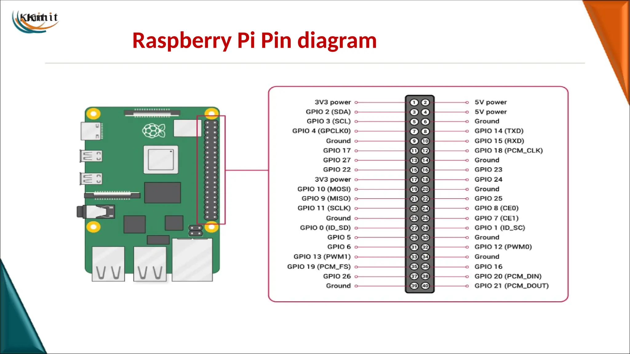
• GPIO Pins: Raspberry Pi comes with a 28 general purpose input/output pins
12.
• Display SerialInterface(DSI): The DSI interface can be used to connect an LCD panel to
Raspberry Pi.
• Camera Serial Interface (CSI): This interface can be used to connect a camera module to
Raspberry Pi.
• SD Card Slot: Raspberry Pi does not have a built in operating system and storage. User can
plug-in an SD card loaded with a Linux image to the SD card slot.
• Power Input: Raspberry Pi has a micro-USB connector for power input.
13.
Raspberry Pi UARTCommunication
Introduction
•UART (Universal Asynchronous Receiver/Transmitter) is a serial communication protocol in
which data is transferred serially i.e. bit by bit.
•.
•UART serial communication protocol uses a defined frame structure for their data bytes.
Frame structure in Asynchronous communication consists:
•START bit: It is a bit with which indicates that serial communication has started and it is always
low.
14.
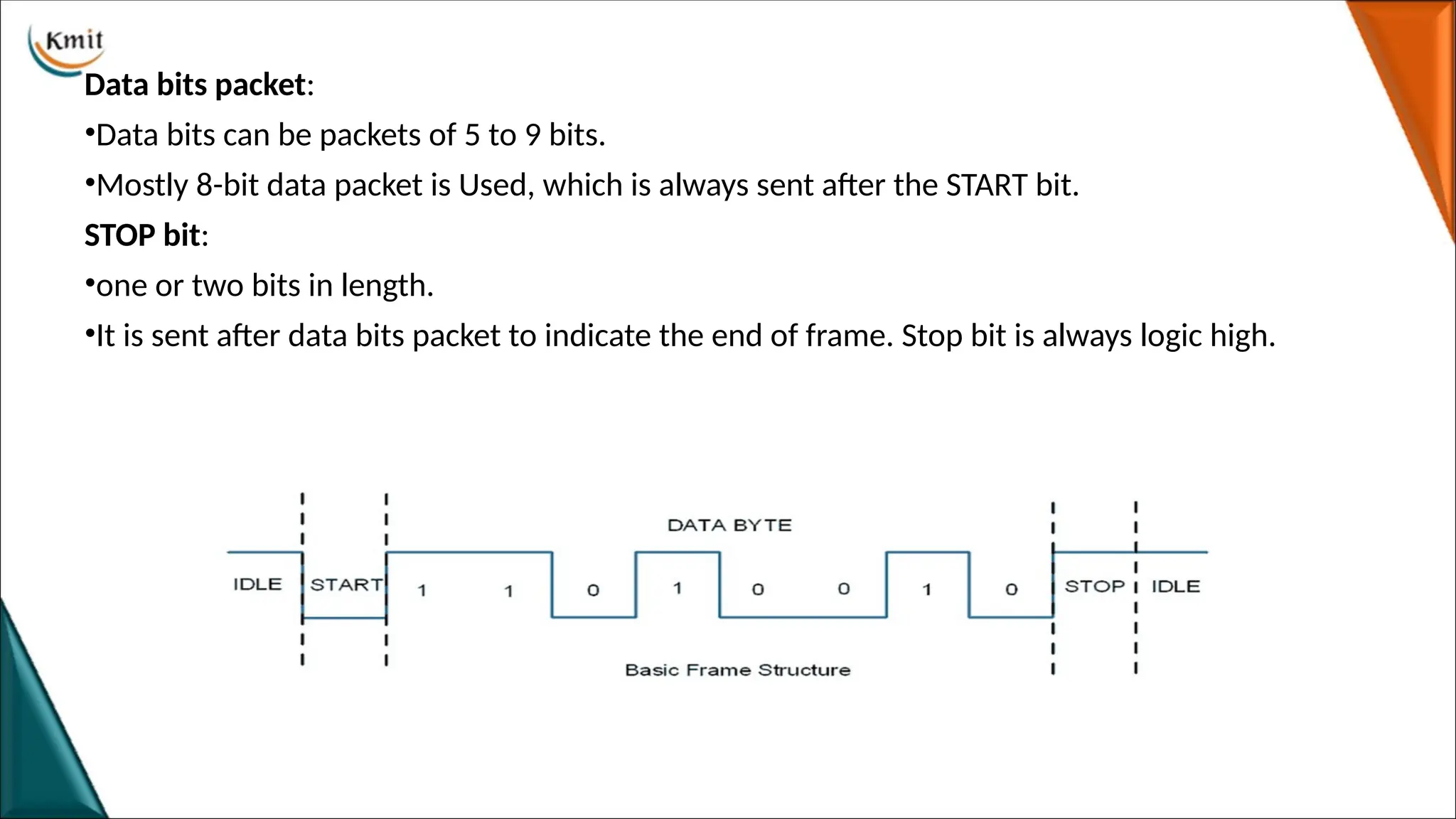
Data bits packet:
•Databits can be packets of 5 to 9 bits.
•Mostly 8-bit data packet is Used, which is always sent after the START bit.
STOP bit:
•one or two bits in length.
•It is sent after data bits packet to indicate the end of frame. Stop bit is always logic high.
15.
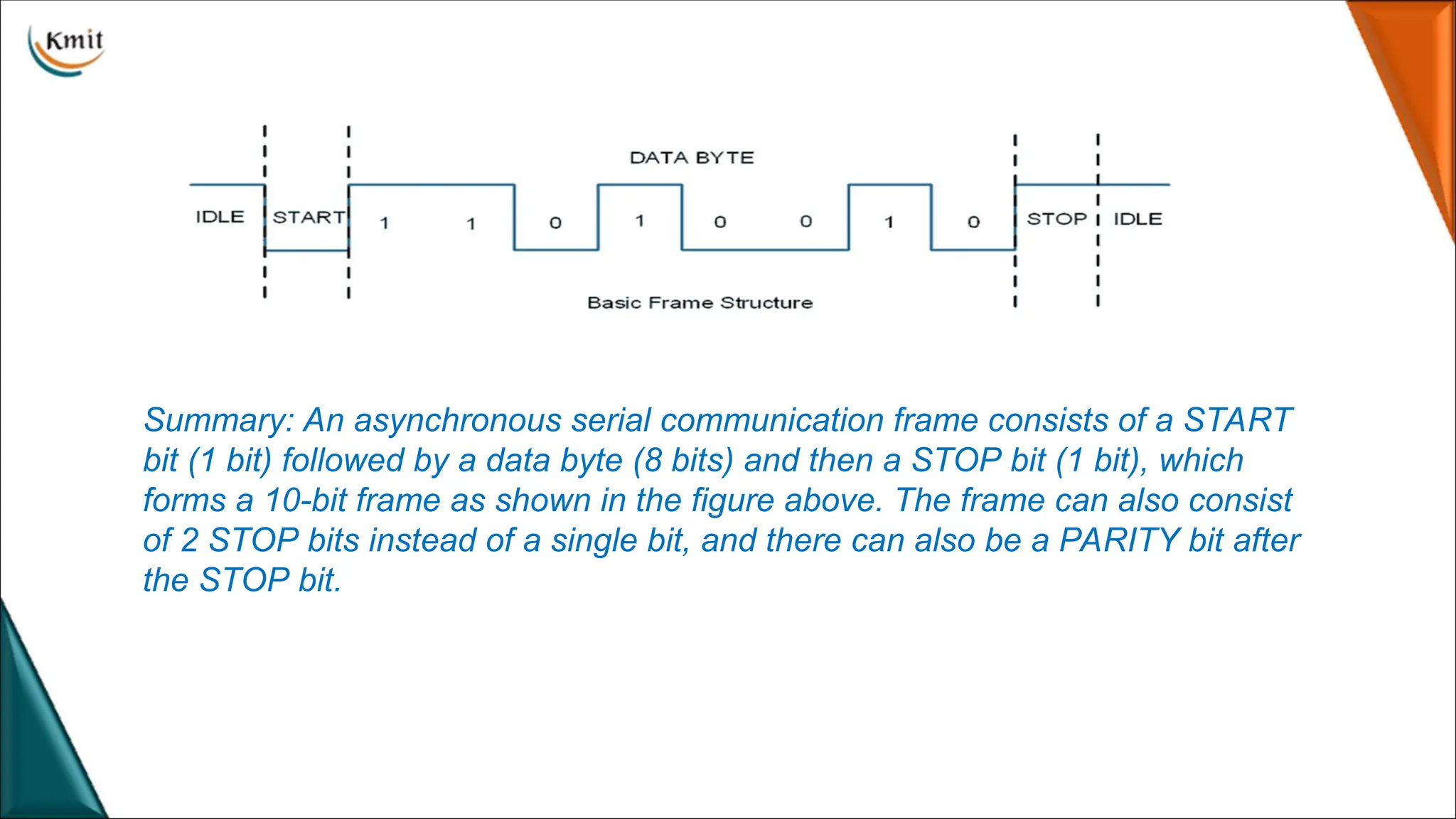
Summary: An asynchronousserial communication frame consists of a START
bit (1 bit) followed by a data byte (8 bits) and then a STOP bit (1 bit), which
forms a 10-bit frame as shown in the figure above. The frame can also consist
of 2 STOP bits instead of a single bit, and there can also be a PARITY bit after
the STOP bit.
16.
Raspberry Pi UART
RaspberryPi has two in-built UART which are as follows:
1.PL011 UART
2.mini UART
•PL011 UART is an ARM based UART.
•PL011 UART has better throughput than mini UART.
•mini UART uses the frequency which is linked to the core frequency of GPU. So as the GPU
core frequency changes, the frequency of UART will also change which in turn will change the
baud rate for UART. This makes the mini UART unstable which may lead to data loss or
corruption.
•To make mini UART stable, fix the core frequency.
•mini UART doesn’t have parity support.
17.
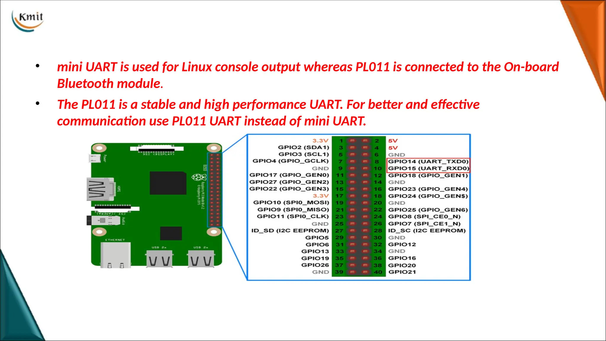
• mini UARTis used for Linux console output whereas PL011 is connected to the On-board
Bluetooth module.
• The PL011 is a stable and high performance UART. For better and effective
communication use PL011 UART instead of mini UART.
18.
Raspberry Pi UARTPins
• RX for Reception. It will connect this pin to the TX pin of the other component.
• TX for Transmission. It will connect this pin to the RX of the other component.
19.
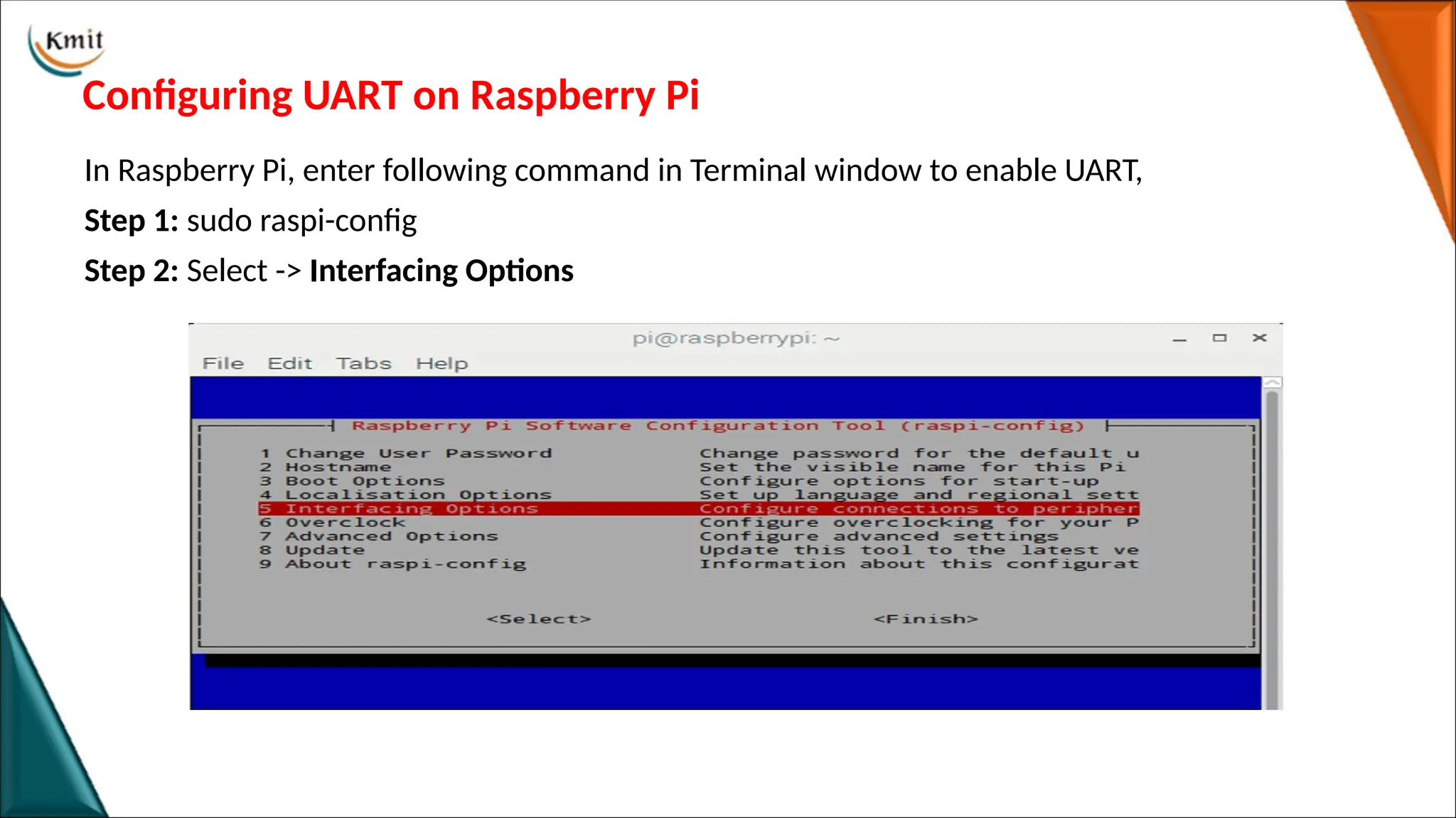
Configuring UART onRaspberry Pi
In Raspberry Pi, enter following command in Terminal window to enable UART,
Step 1: sudo raspi-config
Step 2: Select -> Interfacing Options
20.
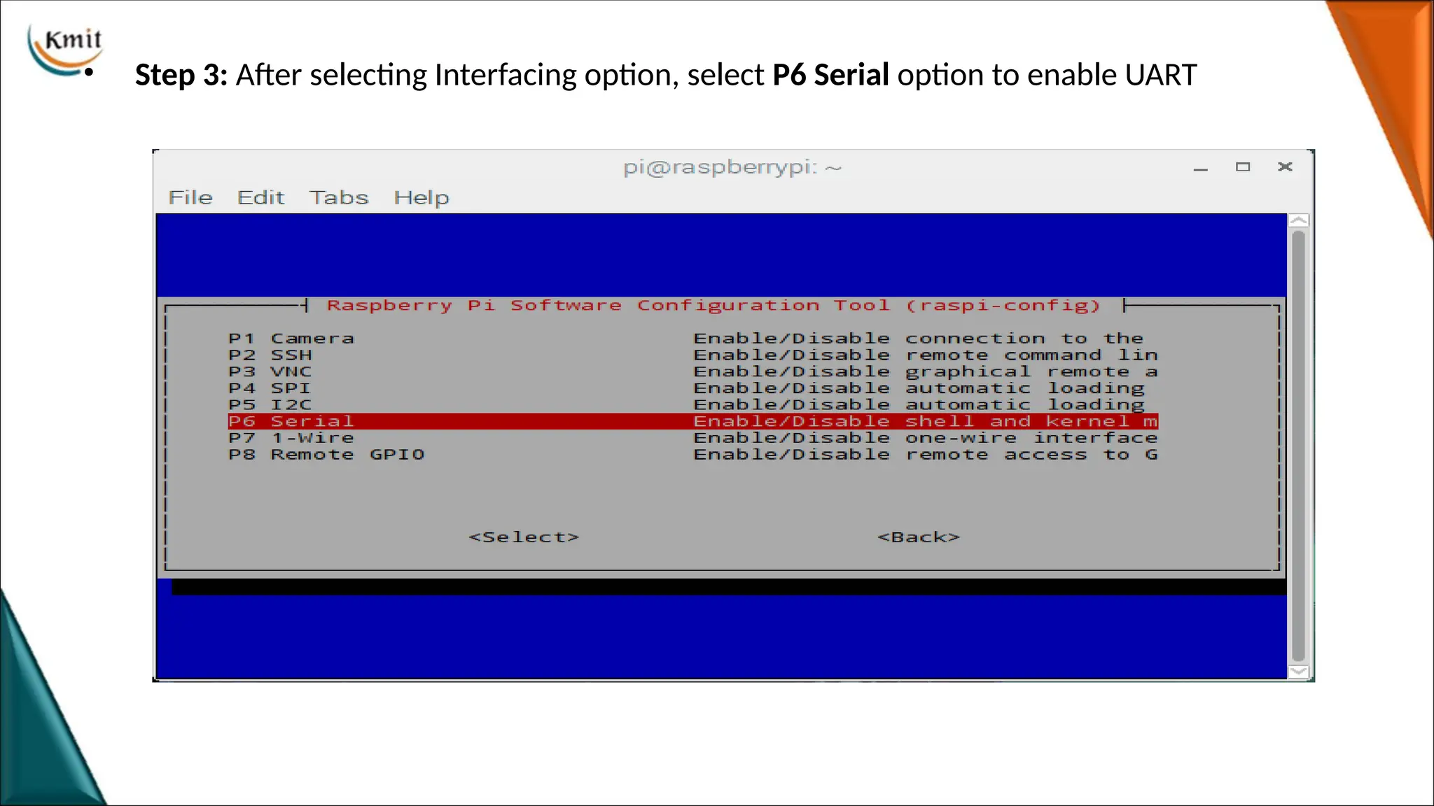
• Step 3:After selecting Interfacing option, select P6 Serial option to enable UART
21.
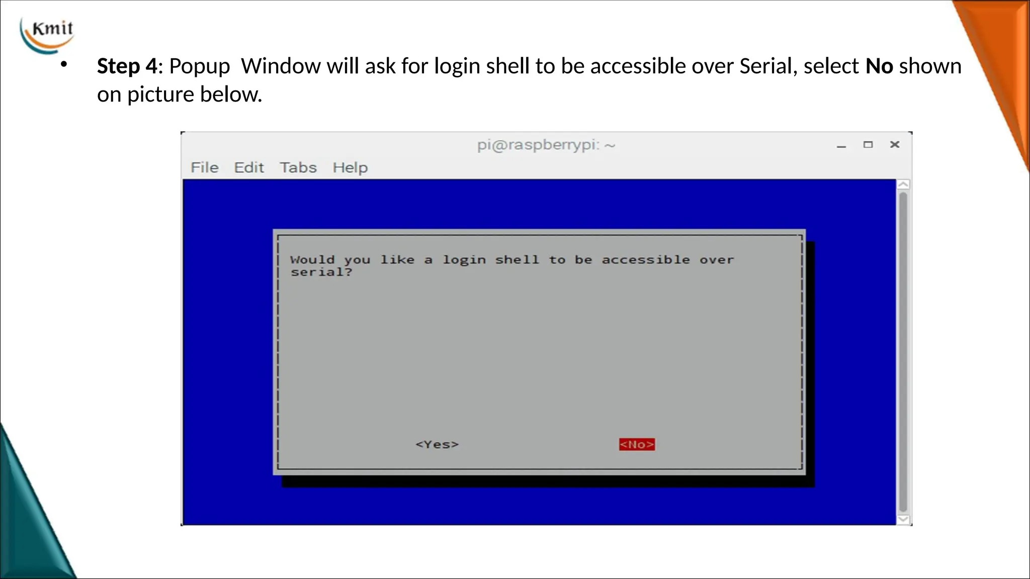
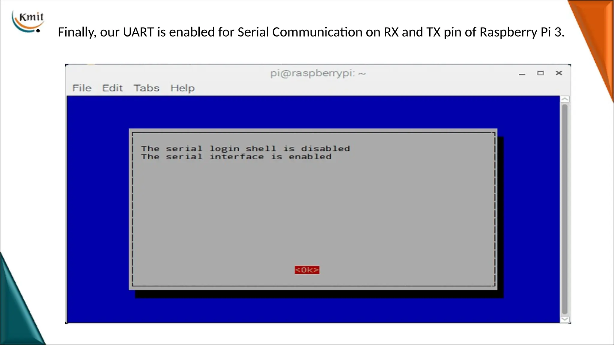
• Step 4:Popup Window will ask for login shell to be accessible over Serial, select No shown
on picture below.
22.
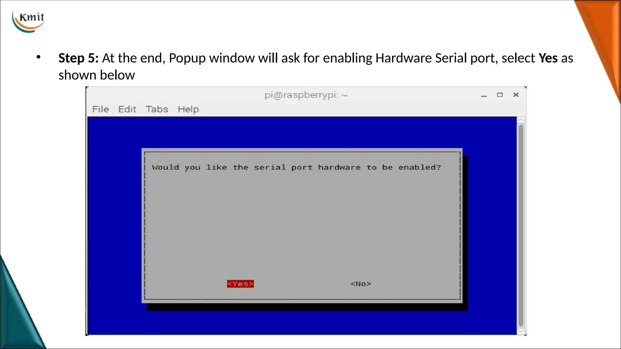
• Step 5:At the end, Popup window will ask for enabling Hardware Serial port, select Yes as
shown below
23.
• Finally, ourUART is enabled for Serial Communication on RX and TX pin of Raspberry Pi 3.
24.
I2C (Inter IntegratedCircuit)
Introduction
•I2C (Inter Integrated Circuit) is a synchronous serial protocol that communicates data between
two devices.
•Master-slave protocol which may have one master or many master and many slaves whereas SPI
has only one master.
•Generally used for communication over short distance.
•It is also called as Two Wire Interface (TWI) protocol.
•The I2C device has 7-bit or 10-bit unique address. So, to access these devices, master should
address them by the 7-bit or 10-bit unique address.
•I2C is used in many applications like reading RTC (Real time clock), accessing external EEPROM
memory. It is also used in sensor modules like gyro, magnetometer etc.
25.
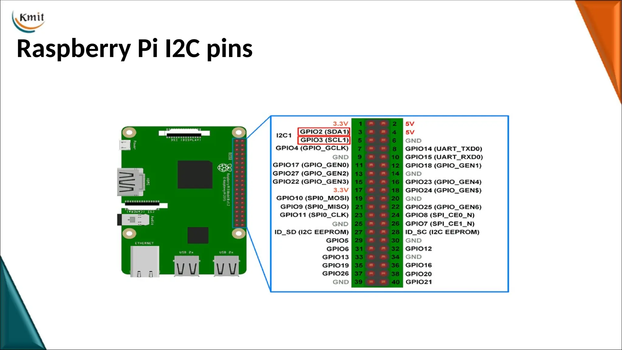
Raspberry Pi I2C
•Raspberry Pi has Broadcom processor having Broadcom Serial Controller (BSC).
• The BSC bus is compliant with the Philips I2C bus.
• It supports both 7-bit and 10-bit addressing.
• It also has BSC2 master which is dedicatedly used with HDMI interface and should
not be accessed by user.
• I2C bus/interface is used to communicate with the external devices like RTC,
MPU6050, Magnetometer, etc with only 2 lines.
26.
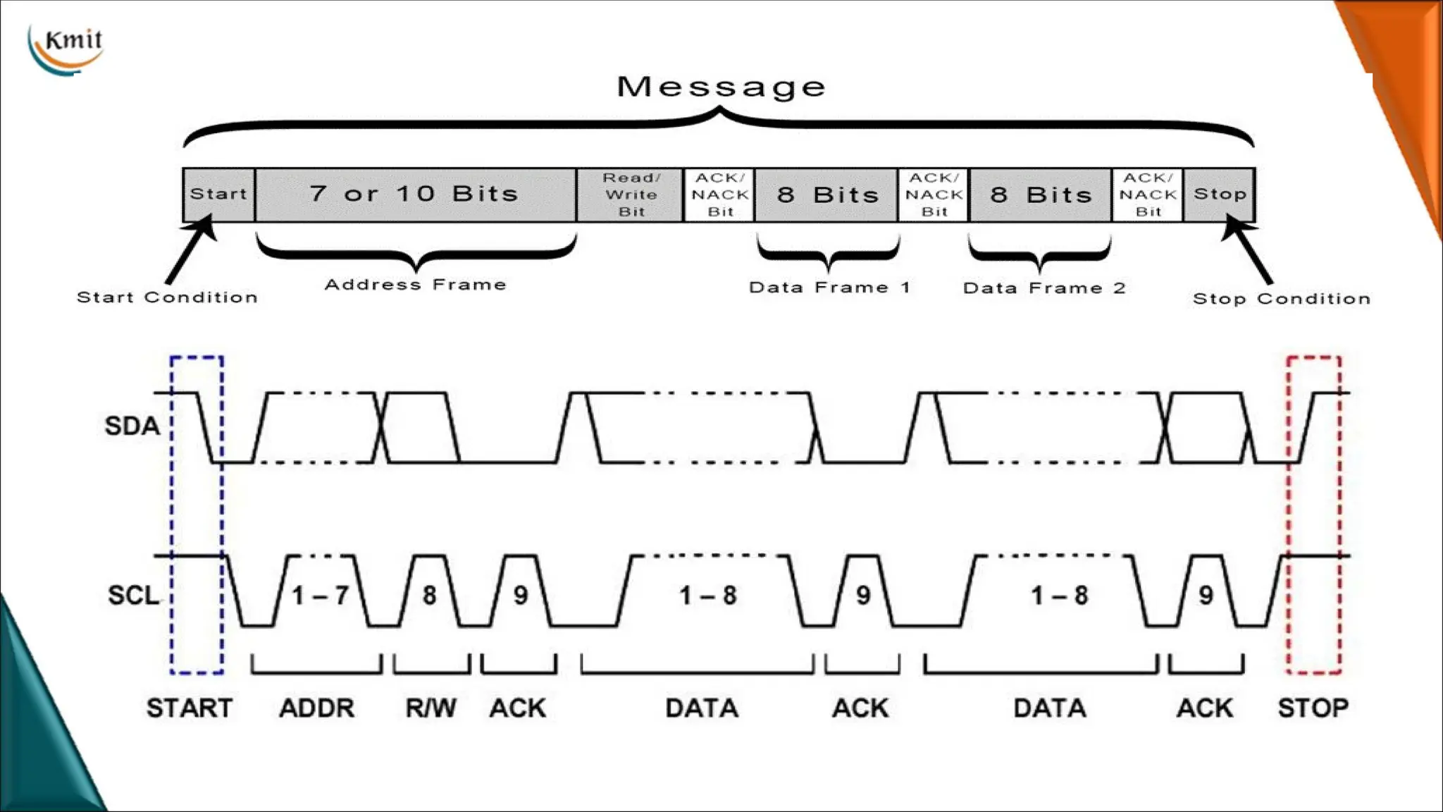
STEPS OF I2CDATA TRANSMISSION
• 1.The master sends the start condition to every connected slave by switching the SDA line from a
high voltage level to a low voltage level before switching the SCL line from high to low:
• 2.The master sends each slave the 7 or 10 bit address of the slave it wants to communicate with,
along with the read/write bit:
• 3.Each slave compares the address sent from the master to its own address. If the address matches,
the slave returns an ACK bit by pulling the SDA line low for one bit. If the address from the master
does not match the slave’s own address, SDA line high.
• 4.The master sends or receives the data frame:
• 5.After each data frame has been transferred, the receiving device returns another ACK bit to the
sender to acknowledge successful receipt of the frame:
• 6.To stop the data transmission, the master sends a stop condition to the slave by switching SCL high
before switching SDA high:
SPI
• SPI isa common communication protocol used by many different devices. Example, SD card
modules, RFID card reader modules, and 2.4 GHz wireless transmitter/receivers all use SPI to
communicate with microcontrollers.
• One unique benefit of SPI is the fact that data can be transferred without interruption. Any number
of bits can be sent or received in a continuous stream.
• Devices communicating via SPI are in a master-slave relationship.
• The master is the controlling device (usually a microcontroller), while the slave (usually a sensor,
display, or memory chip) takes instruction from the master.
30.
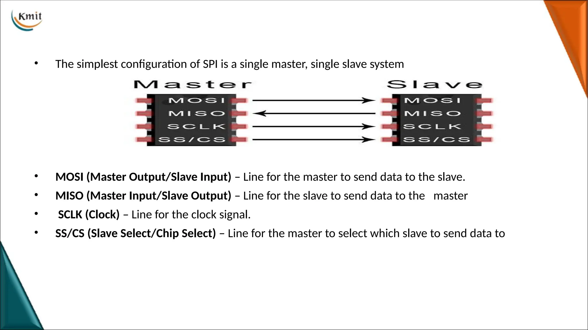
• The simplestconfiguration of SPI is a single master, single slave system
• MOSI (Master Output/Slave Input) – Line for the master to send data to the slave.
• MISO (Master Input/Slave Output) – Line for the slave to send data to the master
• SCLK (Clock) – Line for the clock signal.
• SS/CS (Slave Select/Chip Select) – Line for the master to select which slave to send data to
31.
Raspberry Pi ProgrammingBasics
1.RPi.GPIO API Library
• RPi.GPIO API is the Library to launch input and output pins
• This set of Python files and source is included with Raspbian OS --NOOBS,(Linux
based )
Setup RPi.GPIO
• RPi.GPIO library is available on Raspbian operating system by default and you don’t
need to install it.
• In order To us RPi.GPIO in Python script, you need to put below statement at
the top of your file:
• import RPi.GPIO as GPIO
32.
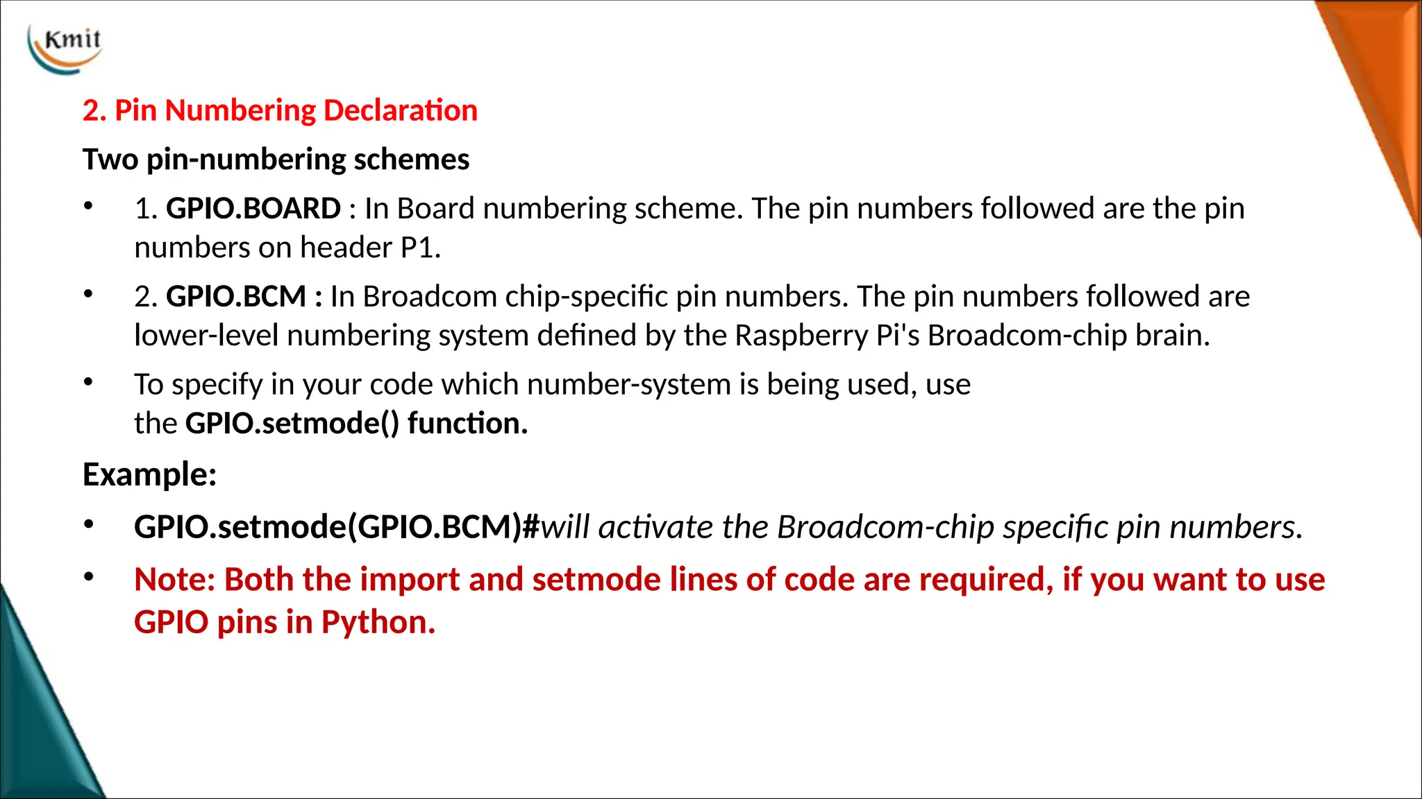
2. Pin NumberingDeclaration
Two pin-numbering schemes
• 1. GPIO.BOARD : In Board numbering scheme. The pin numbers followed are the pin
numbers on header P1.
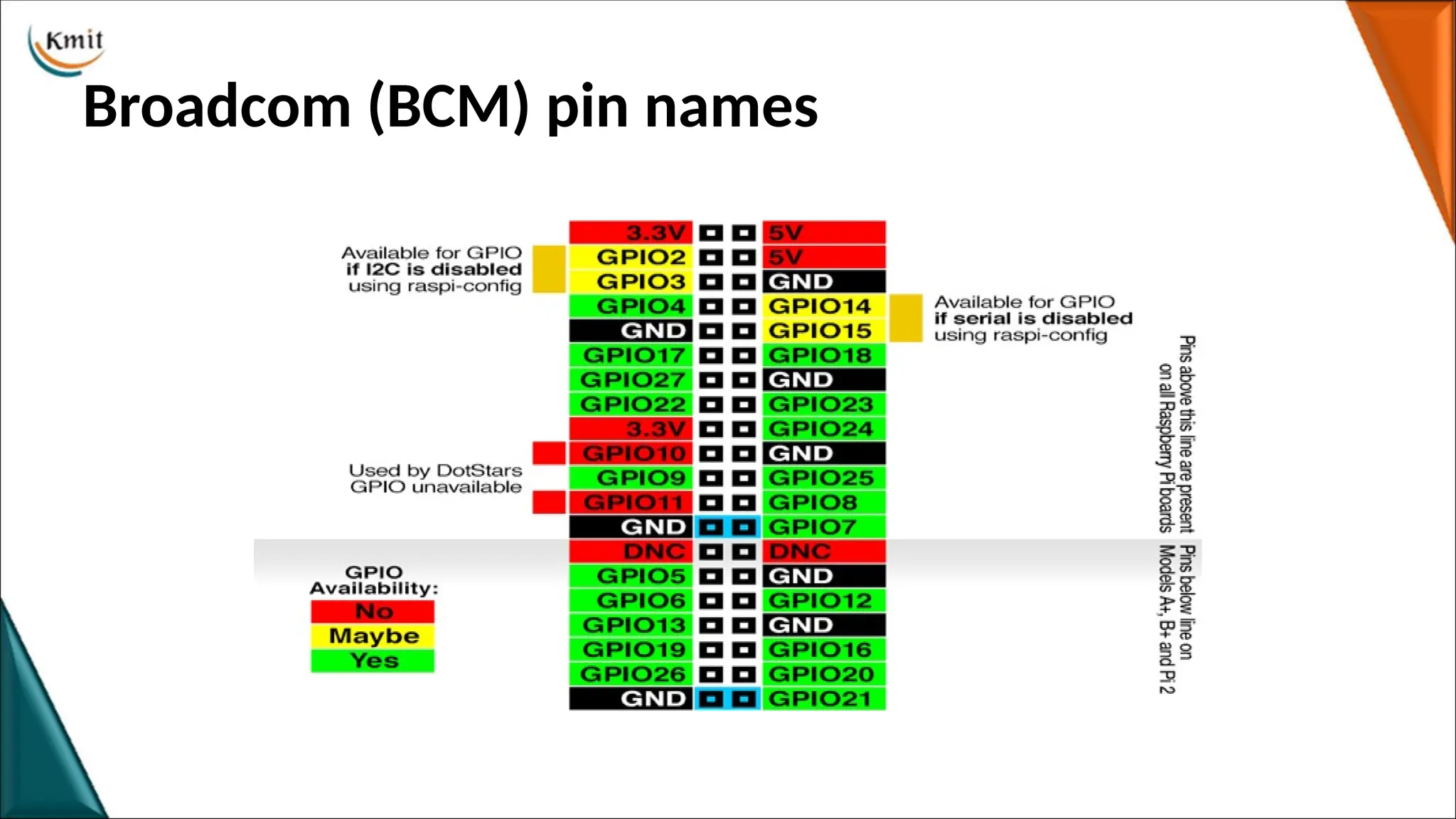
• 2. GPIO.BCM : In Broadcom chip-specific pin numbers. The pin numbers followed are
lower-level numbering system defined by the Raspberry Pi's Broadcom-chip brain.
• To specify in your code which number-system is being used, use
the GPIO.setmode() function.
Example:
• GPIO.setmode(GPIO.BCM)#will activate the Broadcom-chip specific pin numbers.
• Note: Both the import and setmode lines of code are required, if you want to use
GPIO pins in Python.
33.
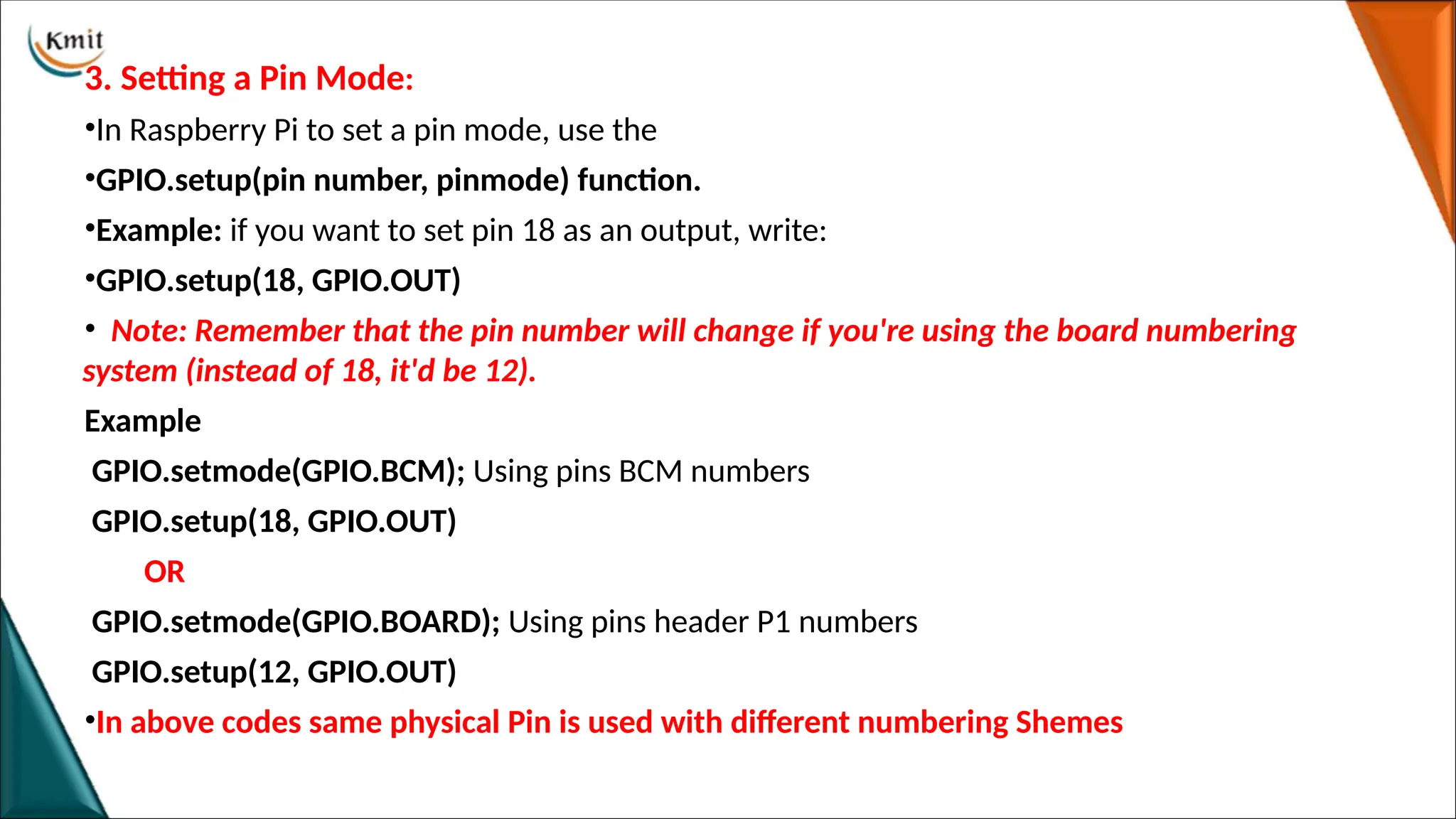
3. Setting aPin Mode:
•In Raspberry Pi to set a pin mode, use the
•GPIO.setup(pin number, pinmode) function.
•Example: if you want to set pin 18 as an output, write:
•GPIO.setup(18, GPIO.OUT)
• Note: Remember that the pin number will change if you're using the board numbering
system (instead of 18, it'd be 12).
Example
GPIO.setmode(GPIO.BCM); Using pins BCM numbers
GPIO.setup(18, GPIO.OUT)
OR
GPIO.setmode(GPIO.BOARD); Using pins header P1 numbers
GPIO.setup(12, GPIO.OUT)
•In above codes same physical Pin is used with different numbering Shemes
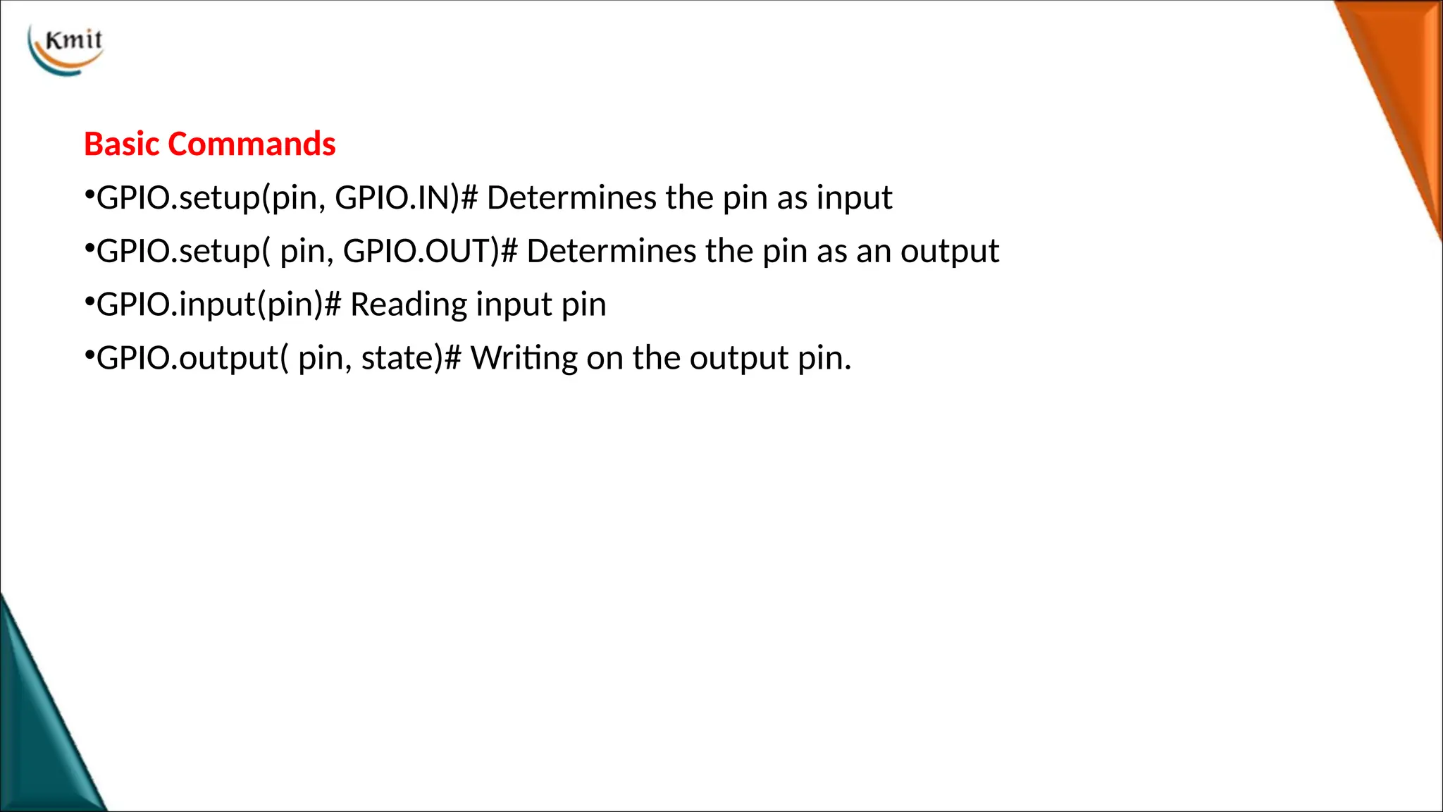
Basic Commands
•GPIO.setup(pin, GPIO.IN)#Determines the pin as input
•GPIO.setup( pin, GPIO.OUT)# Determines the pin as an output
•GPIO.input(pin)# Reading input pin
•GPIO.output( pin, state)# Writing on the output pin.
37.
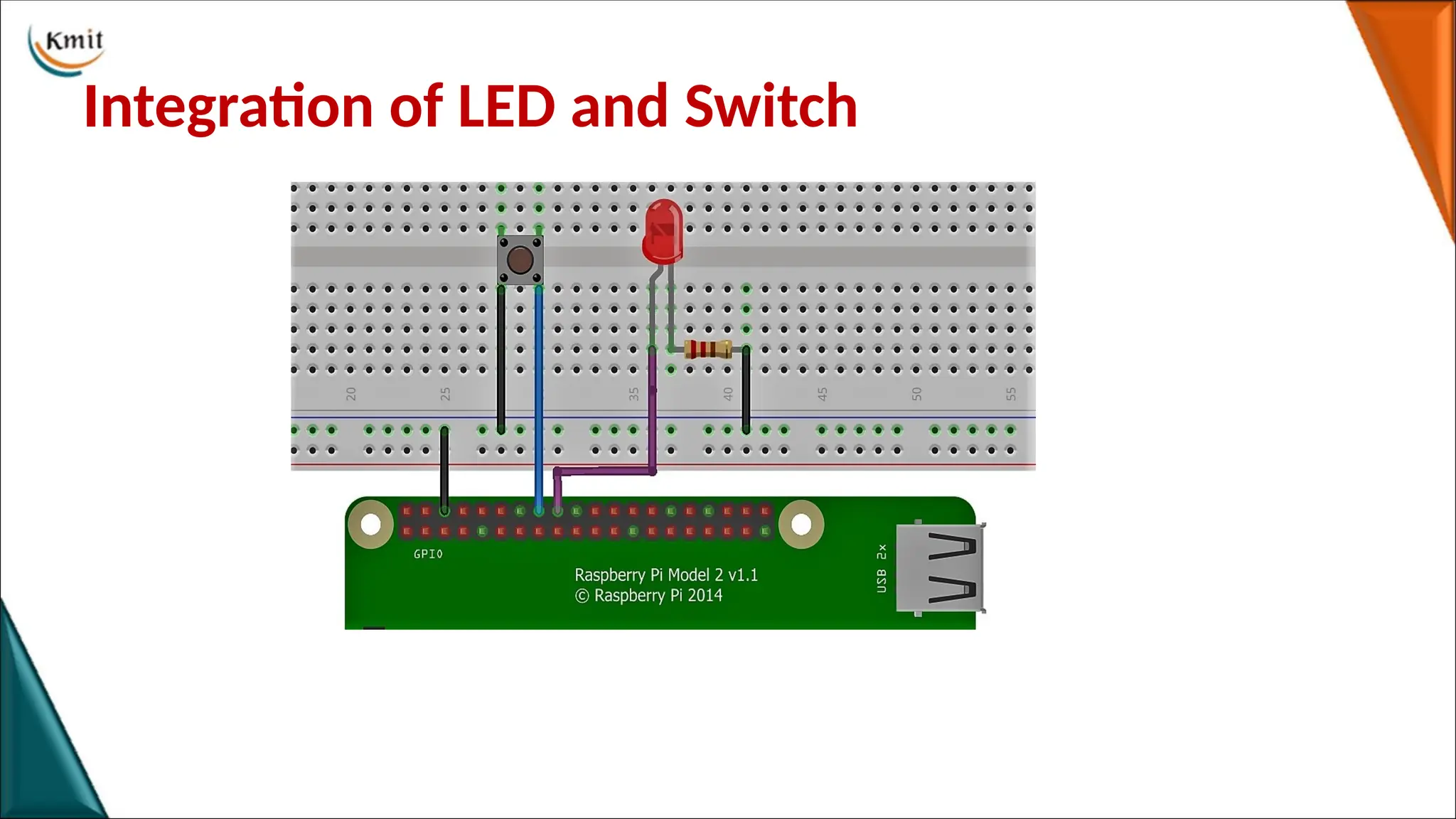
Programming Raspberry Piwith Python
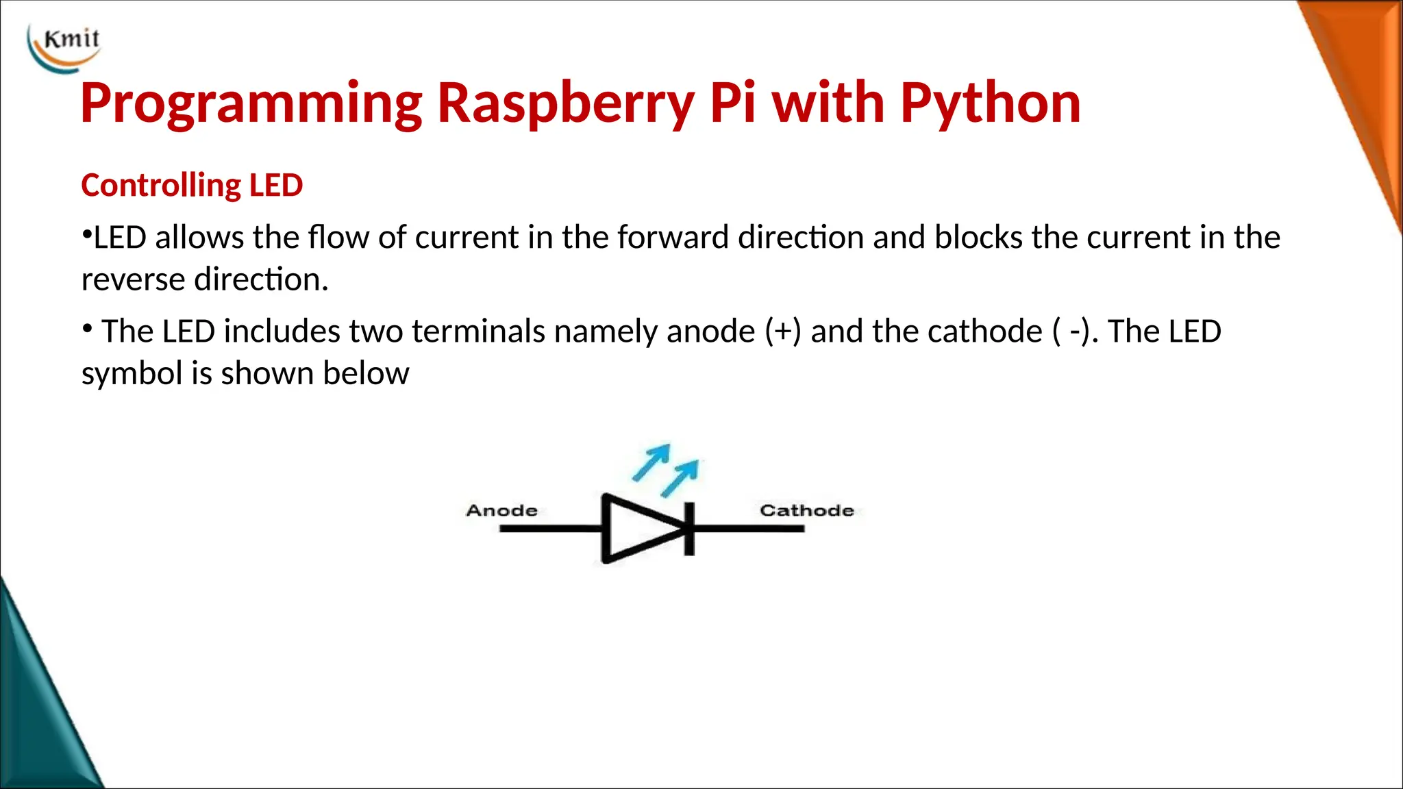
Controlling LED
•LED allows the flow of current in the forward direction and blocks the current in the
reverse direction.
• The LED includes two terminals namely anode (+) and the cathode ( -). The LED
symbol is shown below
Controlling LED ON/OFFPROGRAM
import RPi.GPIO as GPIO
import time
GPIO.setmode(GPIO.BCM)
GPIO.setup(18,GPIO.OUT)
while True:
GPIO.output(18,True)
time.sleep(2)
GPIO.output(18,False)
time.sleep(2)
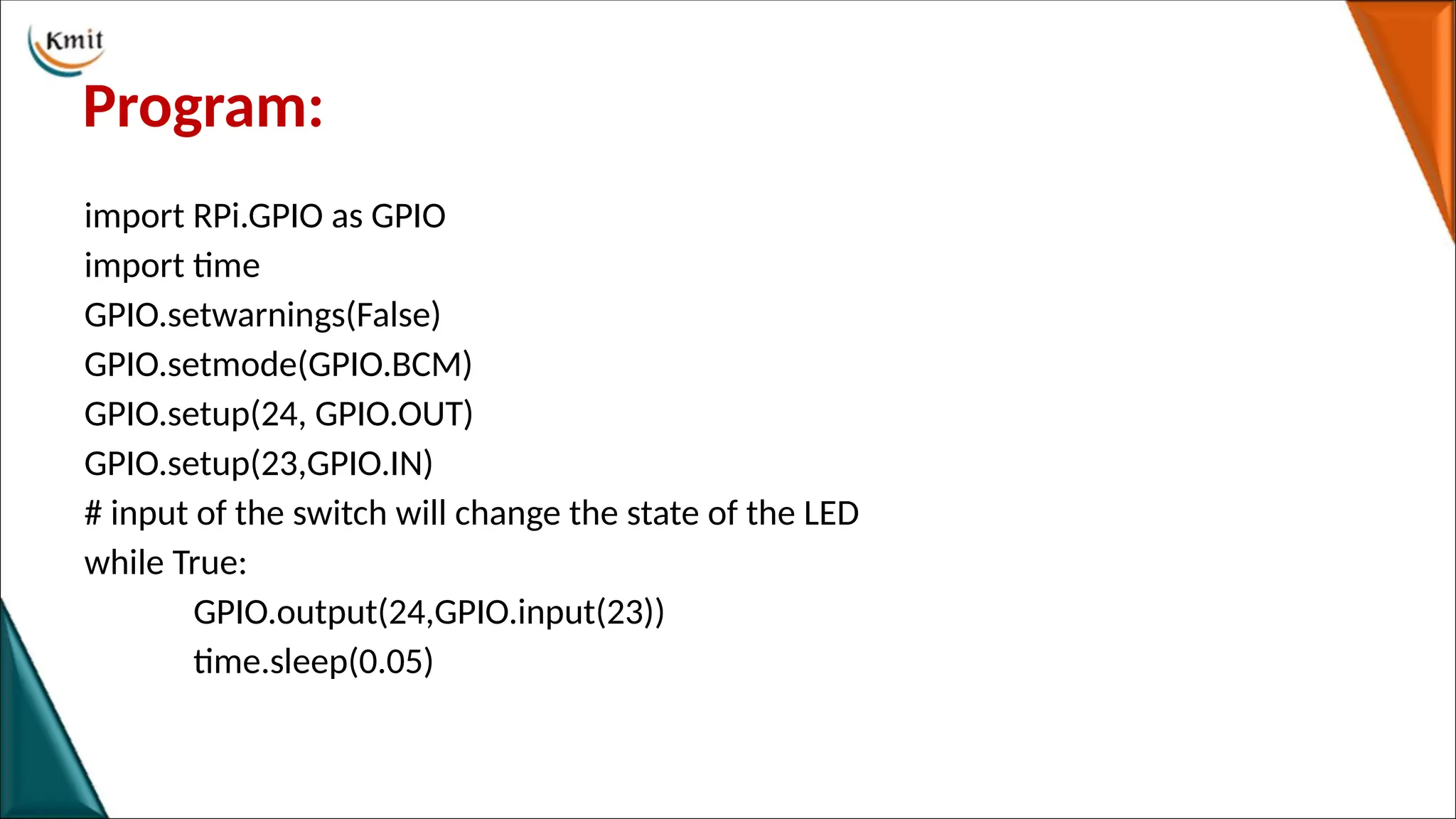
Program:
import RPi.GPIO asGPIO
import time
GPIO.setwarnings(False)
GPIO.setmode(GPIO.BCM)
GPIO.setup(24, GPIO.OUT)
GPIO.setup(23,GPIO.IN)
# input of the switch will change the state of the LED
while True:
GPIO.output(24,GPIO.input(23))
time.sleep(0.05)
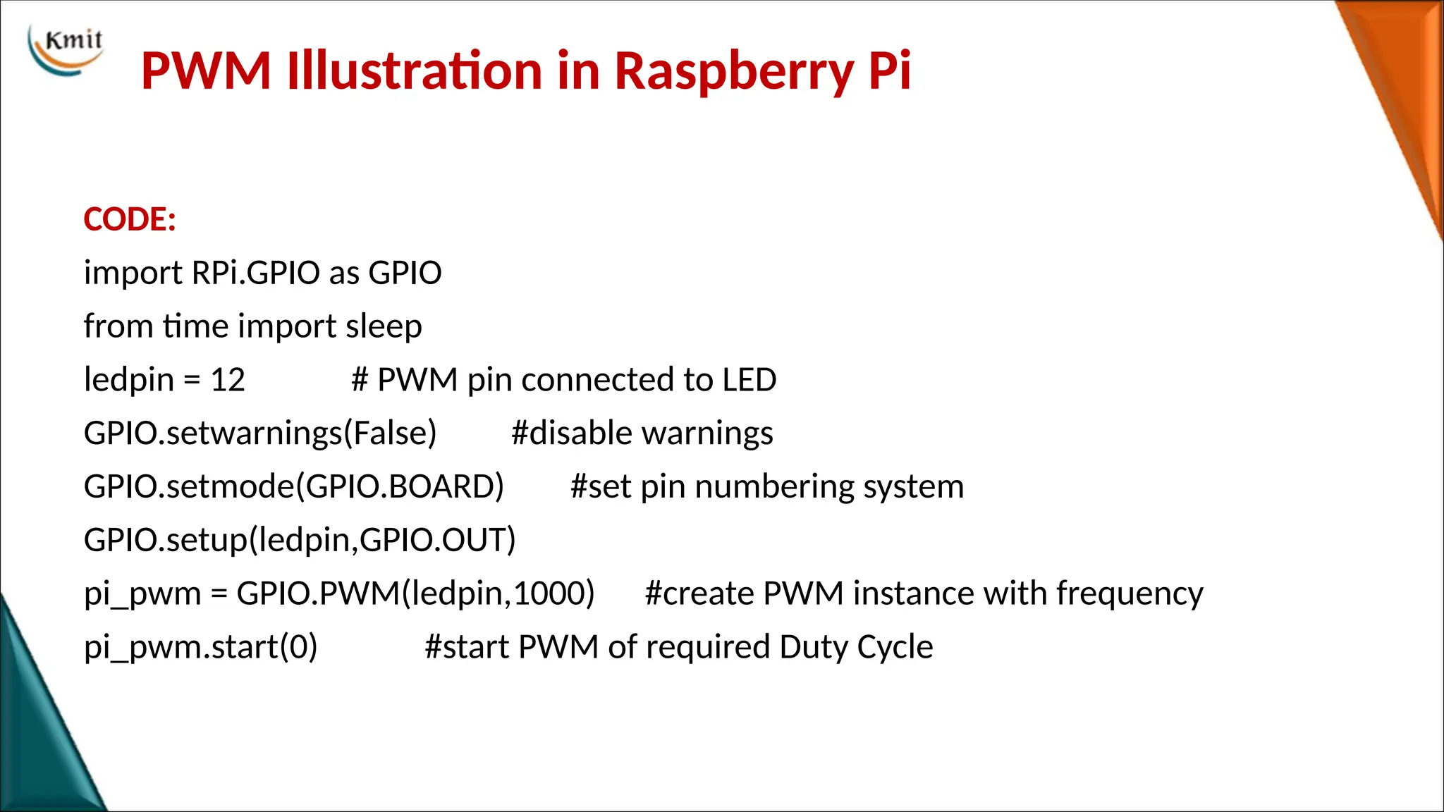
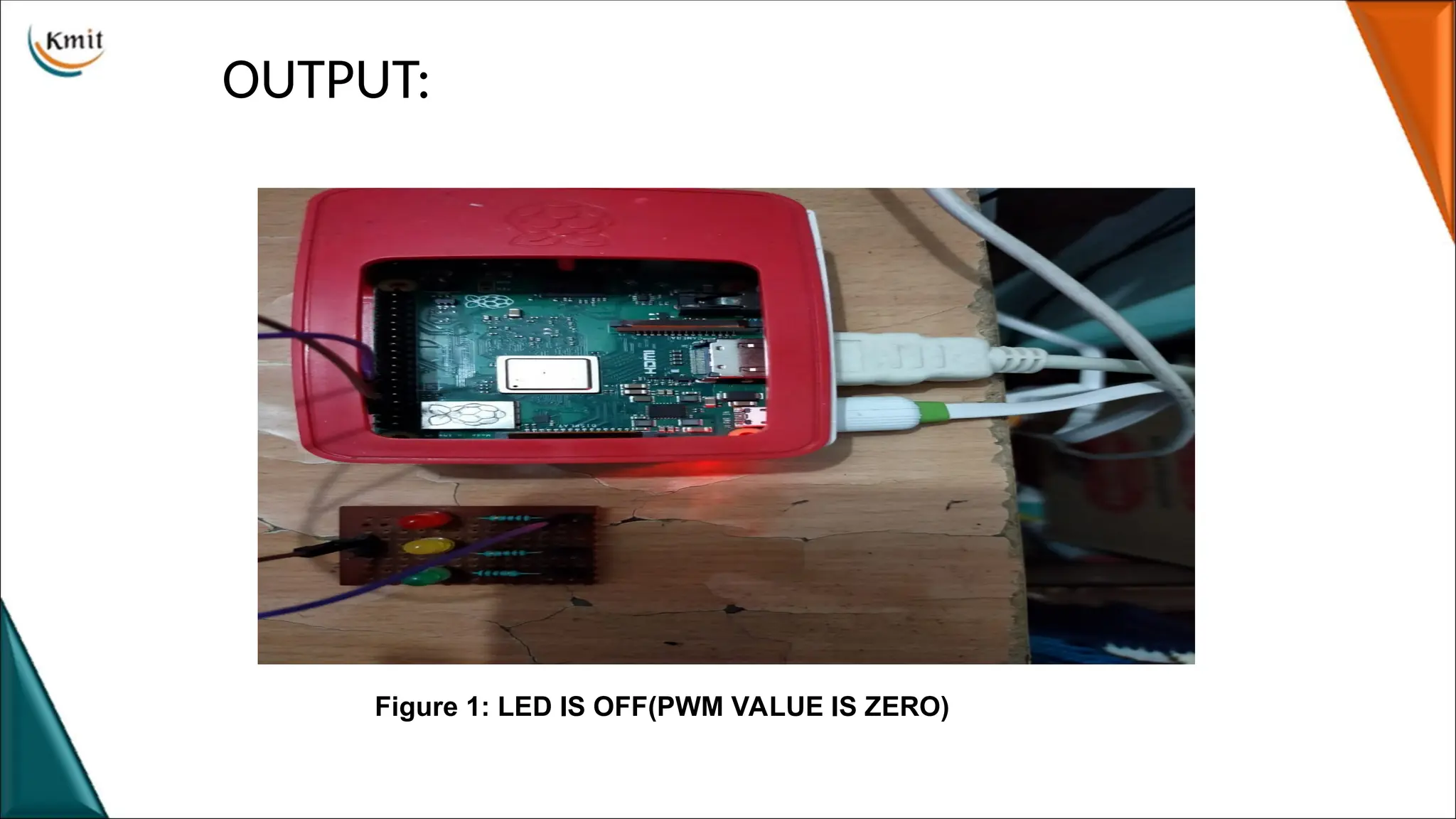
PWM Illustration inRaspberry Pi
CODE:
import RPi.GPIO as GPIO
from time import sleep
ledpin = 12 # PWM pin connected to LED
GPIO.setwarnings(False) #disable warnings
GPIO.setmode(GPIO.BOARD) #set pin numbering system
GPIO.setup(ledpin,GPIO.OUT)
pi_pwm = GPIO.PWM(ledpin,1000) #create PWM instance with frequency
pi_pwm.start(0) #start PWM of required Duty Cycle
45.
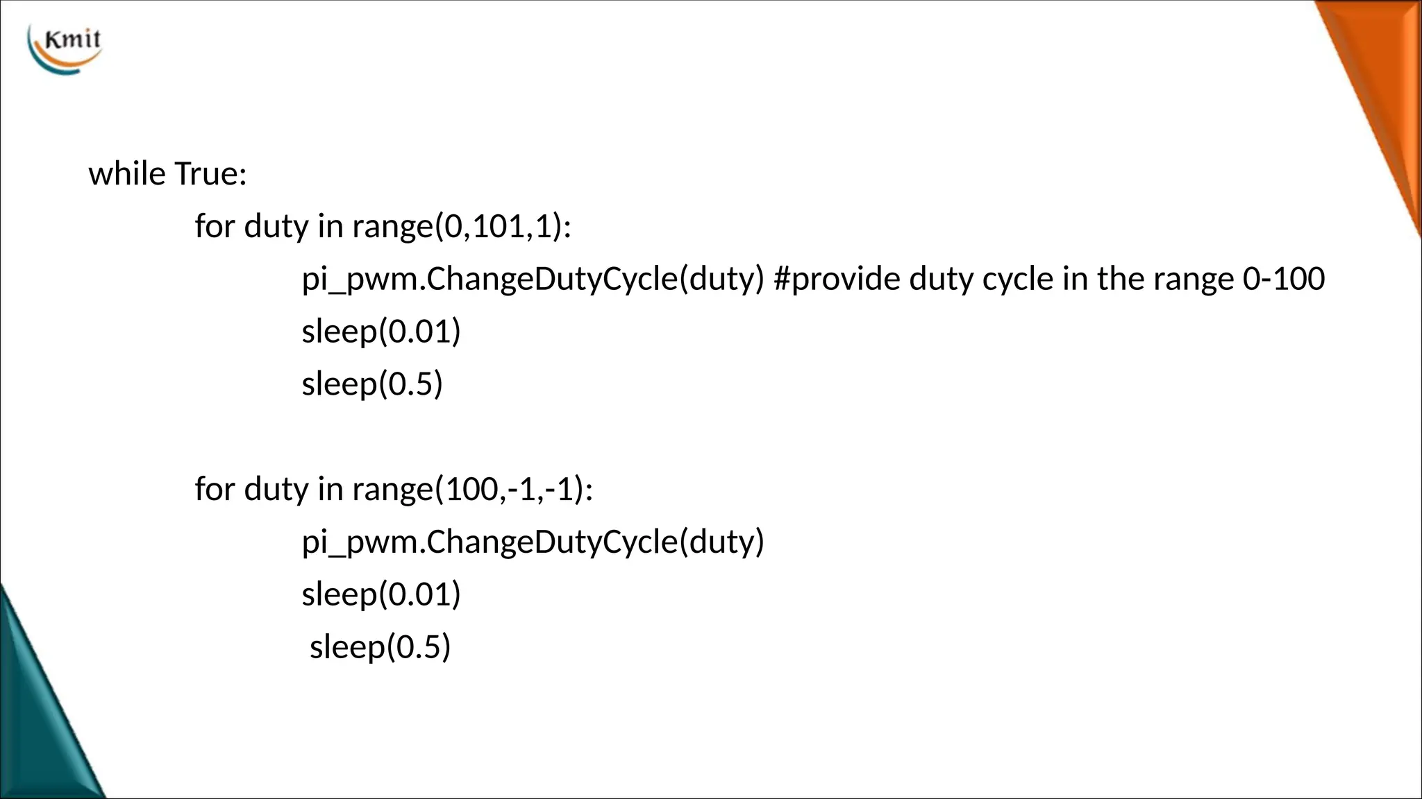
while True:
for dutyin range(0,101,1):
pi_pwm.ChangeDutyCycle(duty) #provide duty cycle in the range 0-100
sleep(0.01)
sleep(0.5)
for duty in range(100,-1,-1):
pi_pwm.ChangeDutyCycle(duty)
sleep(0.01)
sleep(0.5)
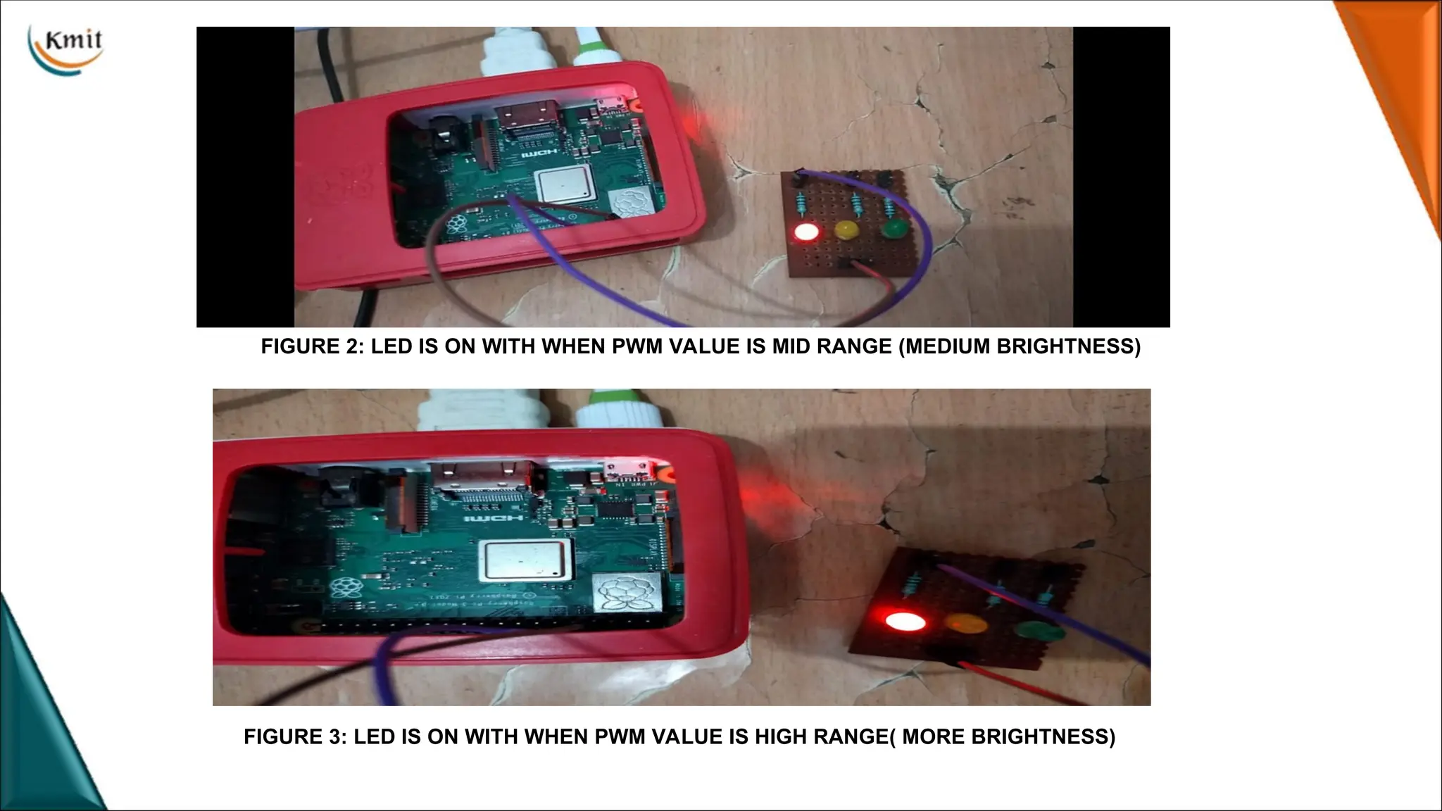
FIGURE 2: LEDIS ON WITH WHEN PWM VALUE IS MID RANGE (MEDIUM BRIGHTNESS)
FIGURE 3: LED IS ON WITH WHEN PWM VALUE IS HIGH RANGE( MORE BRIGHTNESS)
48.
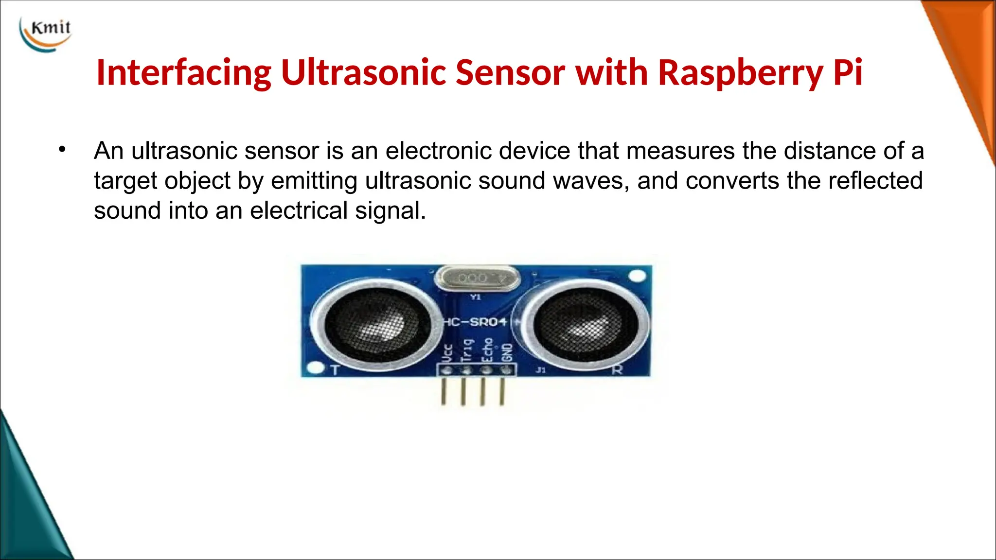
Interfacing Ultrasonic Sensorwith Raspberry Pi
• An ultrasonic sensor is an electronic device that measures the distance of a
target object by emitting ultrasonic sound waves, and converts the reflected
sound into an electrical signal.
49.
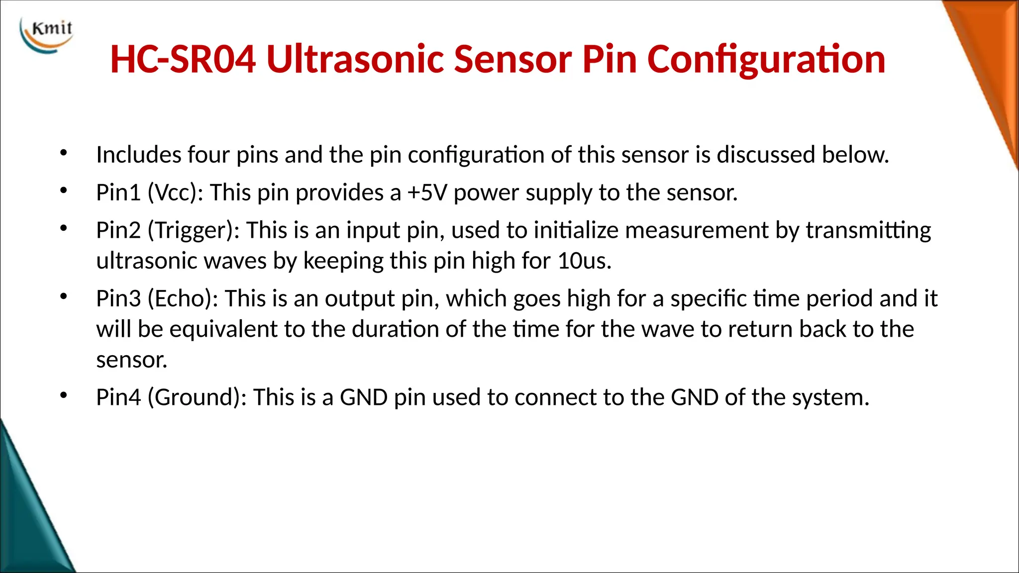
HC-SR04 Ultrasonic SensorPin Configuration
• Includes four pins and the pin configuration of this sensor is discussed below.
• Pin1 (Vcc): This pin provides a +5V power supply to the sensor.
• Pin2 (Trigger): This is an input pin, used to initialize measurement by transmitting
ultrasonic waves by keeping this pin high for 10us.
• Pin3 (Echo): This is an output pin, which goes high for a specific time period and it
will be equivalent to the duration of the time for the wave to return back to the
sensor.
• Pin4 (Ground): This is a GND pin used to connect to the GND of the system.
50.
Features:
• The powersupply is +5V DC
• Dimension is 45mm x 20mm x 15mm
• Quiescent current used for this sensor is <2mA
• The input pulse width of trigger is10uS
• Operating current is 15mA
• Measuring angle is 30 degrees
• The distance range is 2cm to 800 cm
• Resolution is 0.3 cm
• Effectual Angle is <15°
• Operating frequency range is 40Hz
• Accuracy is 3mm
51.
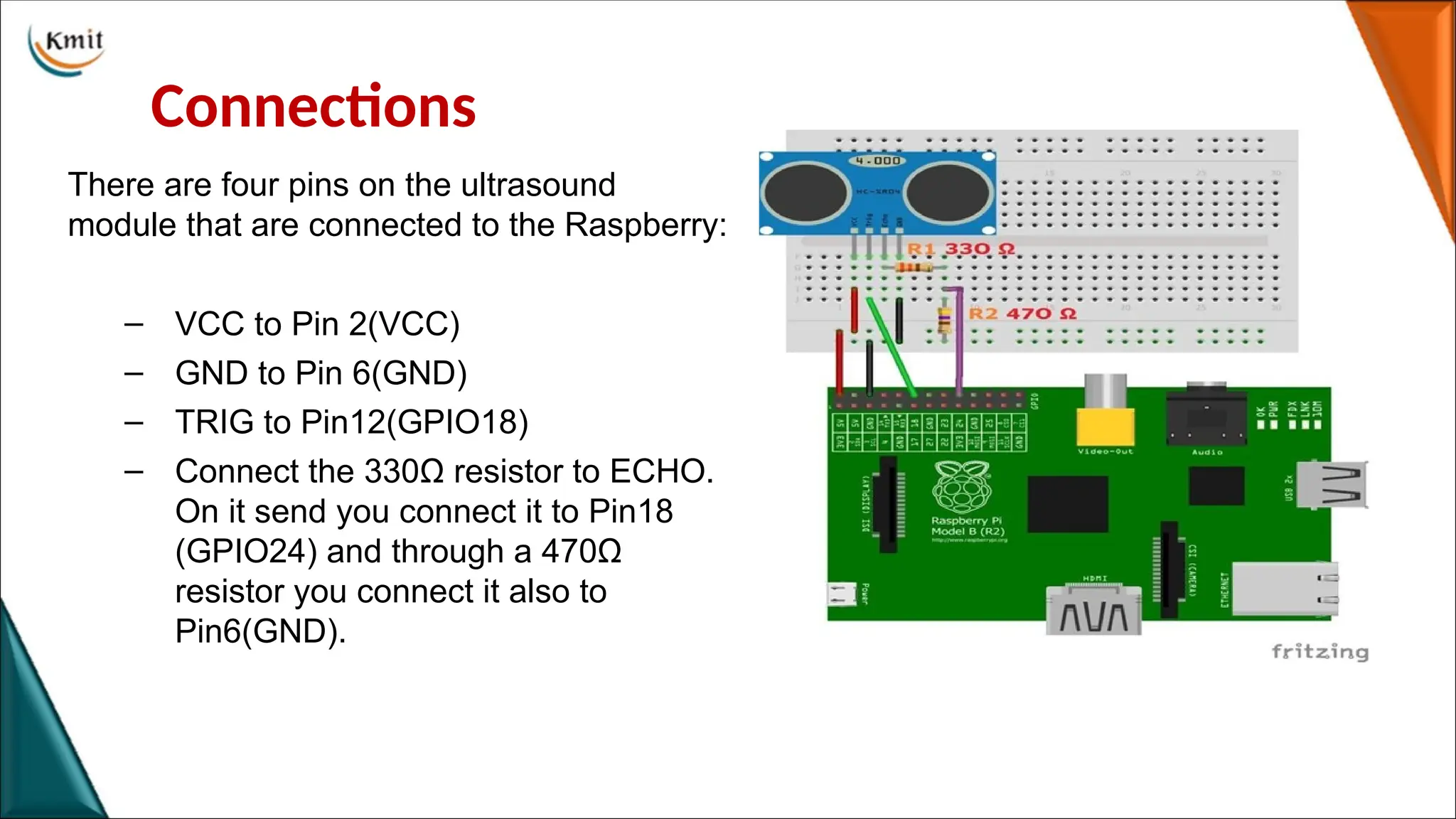
Connections
There are fourpins on the ultrasound
module that are connected to the Raspberry:
– VCC to Pin 2(VCC)
– GND to Pin 6(GND)
– TRIG to Pin12(GPIO18)
– Connect the 330Ω resistor to ECHO.
On it send you connect it to Pin18
(GPIO24) and through a 470Ω
resistor you connect it also to
Pin6(GND).
52.
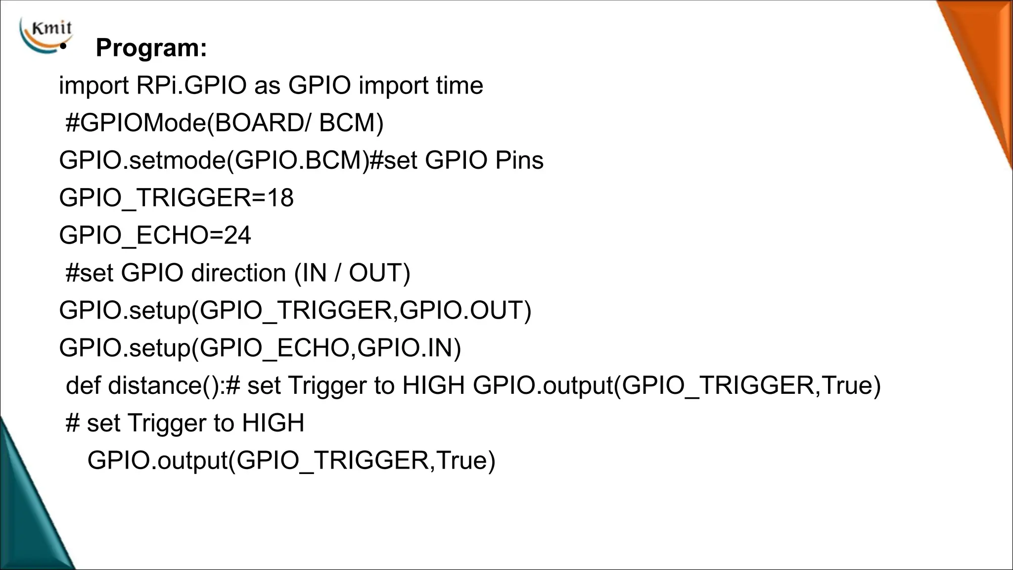
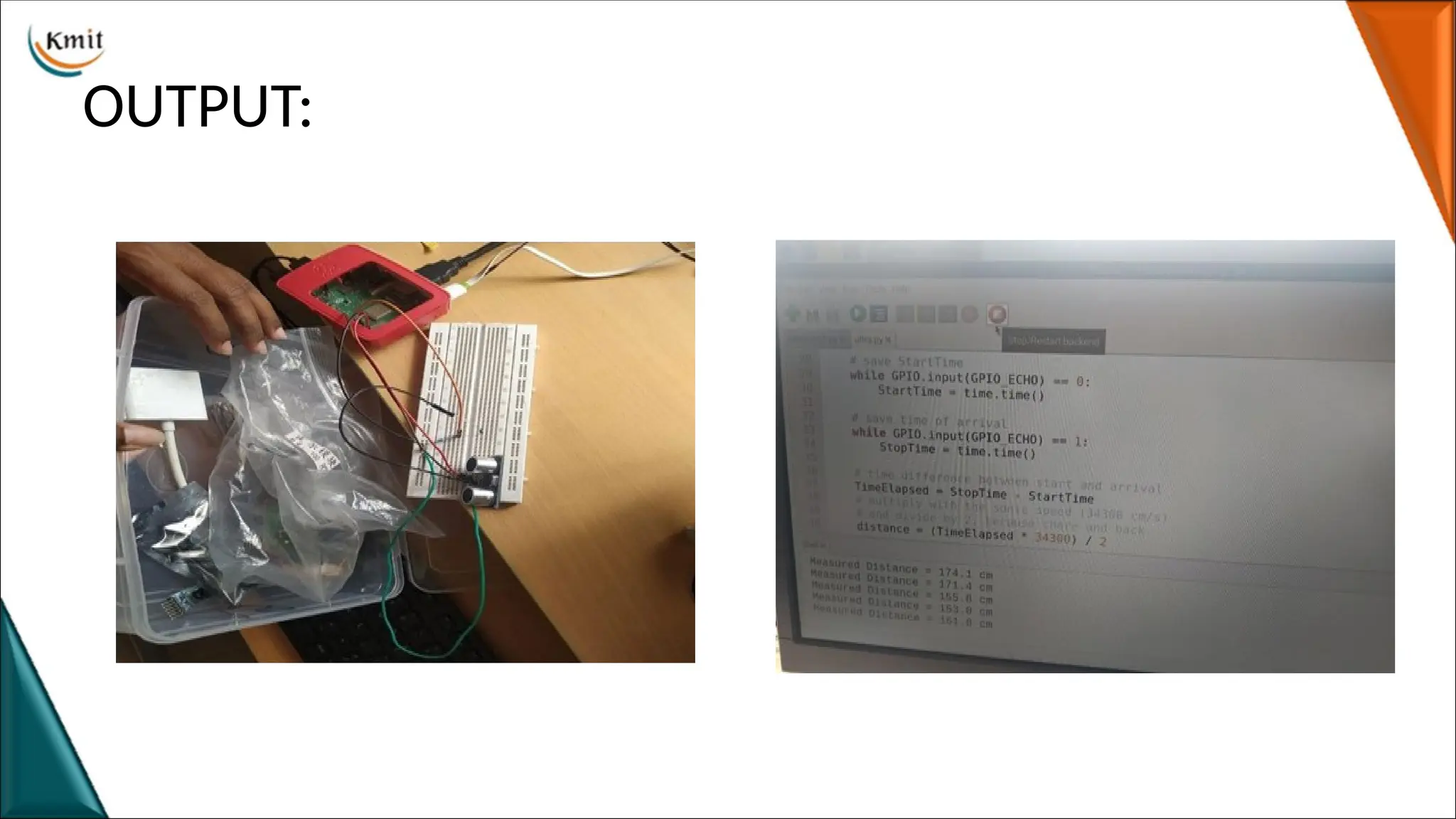
• Program:
import RPi.GPIOas GPIO import time
#GPIOMode(BOARD/ BCM)
GPIO.setmode(GPIO.BCM)#set GPIO Pins
GPIO_TRIGGER=18
GPIO_ECHO=24
#set GPIO direction (IN / OUT)
GPIO.setup(GPIO_TRIGGER,GPIO.OUT)
GPIO.setup(GPIO_ECHO,GPIO.IN)
def distance():# set Trigger to HIGH GPIO.output(GPIO_TRIGGER,True)
# set Trigger to HIGH
GPIO.output(GPIO_TRIGGER,True)
53.
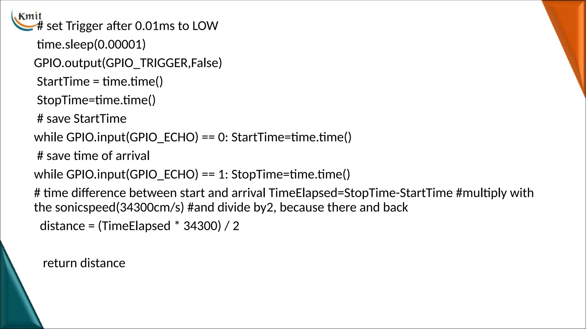
# set Triggerafter 0.01ms to LOW
time.sleep(0.00001)
GPIO.output(GPIO_TRIGGER,False)
StartTime = time.time()
StopTime=time.time()
# save StartTime
while GPIO.input(GPIO_ECHO) == 0: StartTime=time.time()
# save time of arrival
while GPIO.input(GPIO_ECHO) == 1: StopTime=time.time()
# time difference between start and arrival TimeElapsed=StopTime-StartTime #multiply with
the sonicspeed(34300cm/s) #and divide by2, because there and back
distance = (TimeElapsed * 34300) / 2
return distance
54.
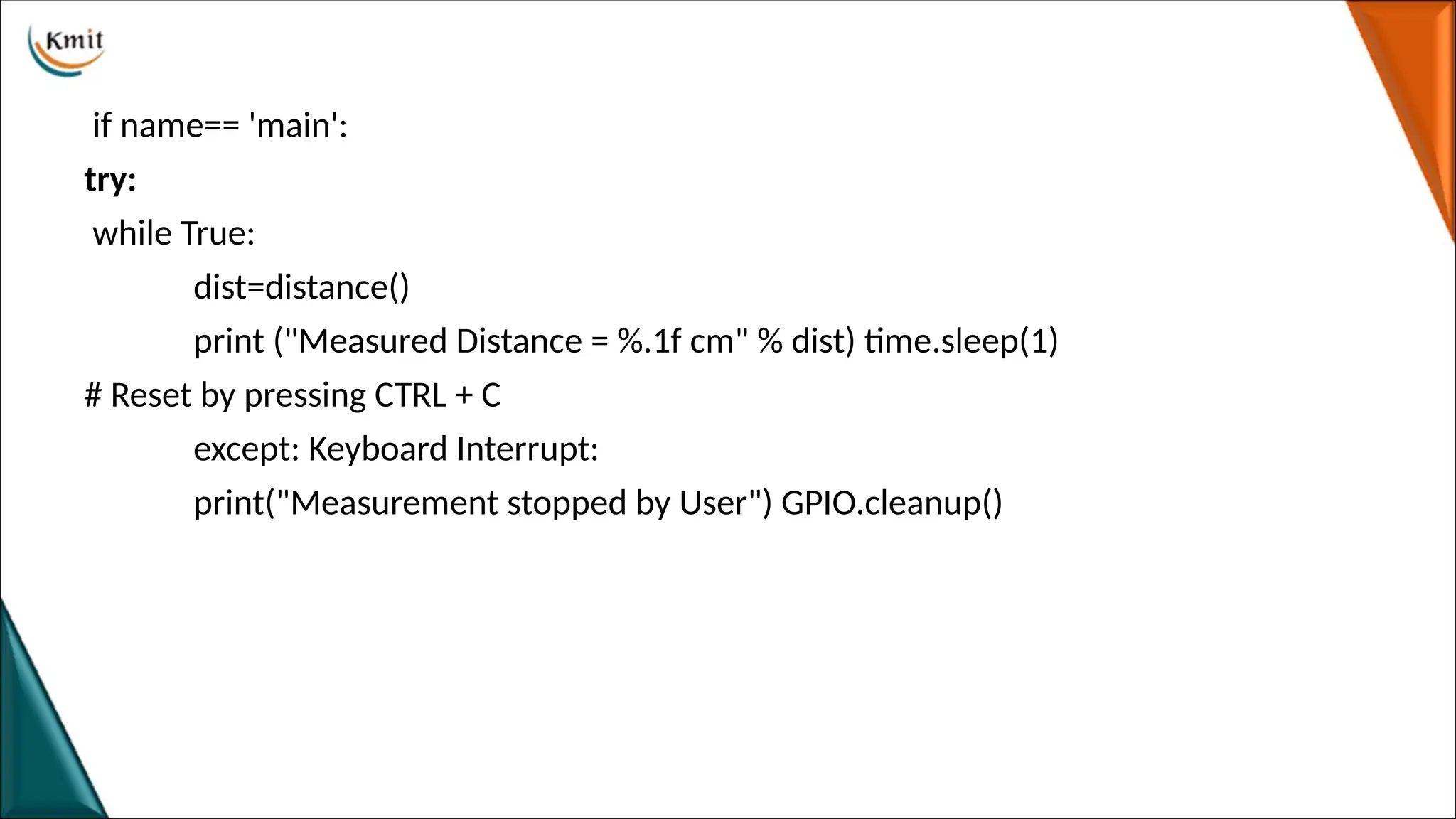
if name== 'main':
try:
whileTrue:
dist=distance()
print ("Measured Distance = %.1f cm" % dist) time.sleep(1)
# Reset by pressing CTRL + C
except: Keyboard Interrupt:
print("Measurement stopped by User") GPIO.cleanup()
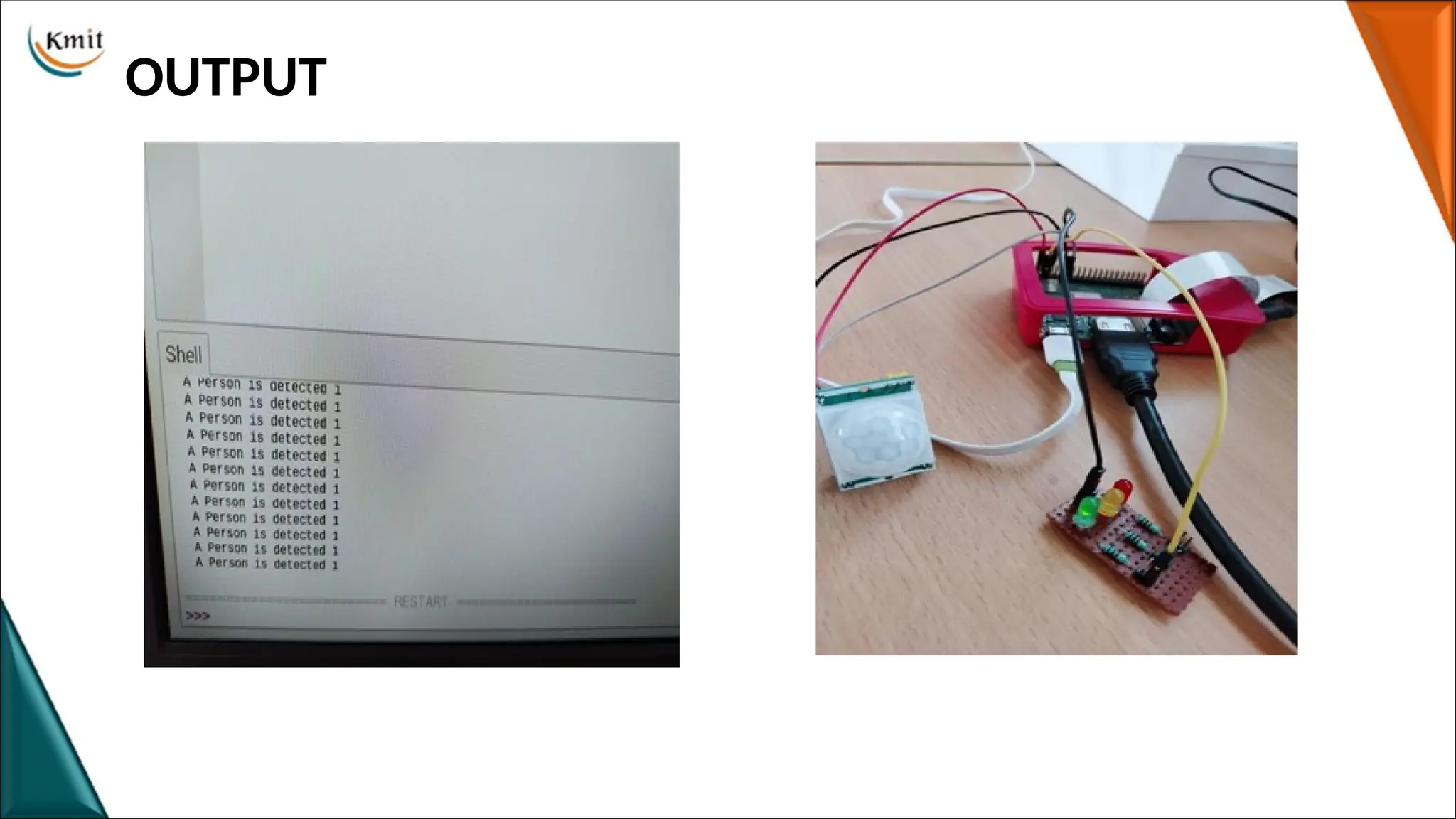
Interfacing PIR Sensorwith Raspberry Pi
PIR SENSOR
•A passive infrared sensor (PIR sensor) is an electronic sensor that measures infrared (IR) light
radiating from objects in its field of view.(range)
•PIR sensors are commonly used in security alarms and automatic lighting applications.
•PIR sensors detect general movement, but do not give information on who or what moved.
PIN DESCRIPTION
•Pin1 corresponds to the drain terminal of the device, which connected to the positive supply
5V DC.
•Pin2 corresponds to the source terminal of the device, which connects to the ground terminal
via a 100K or 47K resistor. The Pin2 is the output pin of the sensor.
•Pin3 of the sensor connected to the ground.
57.
PIR WORKING
• ThePIR sensor itself has two slots in it, each slot is made of a special material
that is sensitive to IR. When the sensor is idle, both slots detect the same
amount of IR, the ambient amount radiated from the room or walls or outdoors.
• When a warm body like a human or animal passes by, it first intercepts one half
of the PIR sensor, which causes a positive differential change between the two
halves. When the warm body leaves the sensing area, the reverse happens,
whereby the sensor generates a negative differential change. These change pulses
are what is detected.
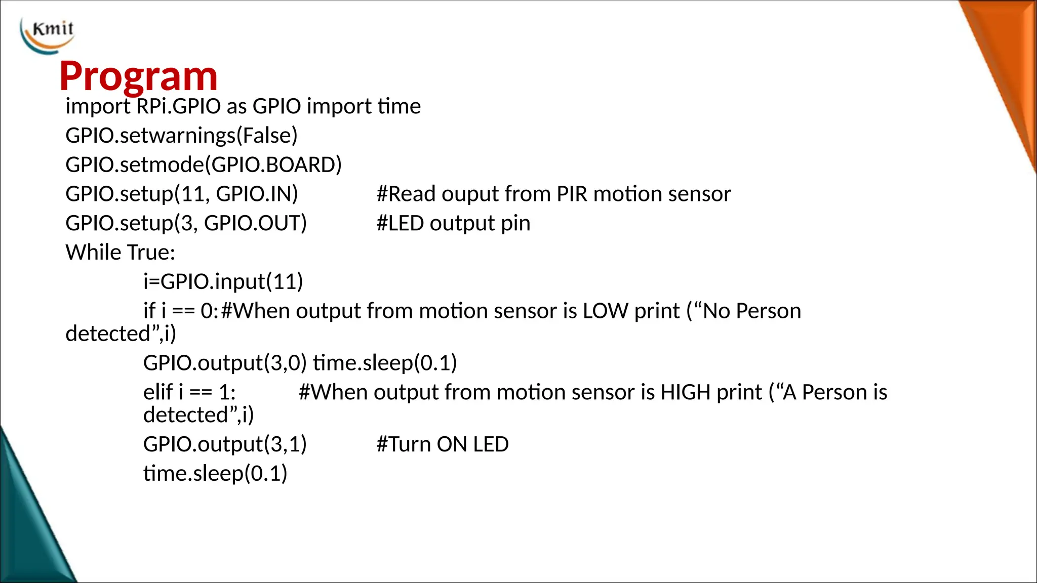
Program
import RPi.GPIO asGPIO import time
GPIO.setwarnings(False)
GPIO.setmode(GPIO.BOARD)
GPIO.setup(11, GPIO.IN) #Read ouput from PIR motion sensor
GPIO.setup(3, GPIO.OUT) #LED output pin
While True:
i=GPIO.input(11)
if i == 0:#When output from motion sensor is LOW print (“No Person
detected”,i)
GPIO.output(3,0) time.sleep(0.1)
elif i == 1: #When output from motion sensor is HIGH print (“A Person is
detected”,i)
GPIO.output(3,1) #Turn ON LED
time.sleep(0.1)
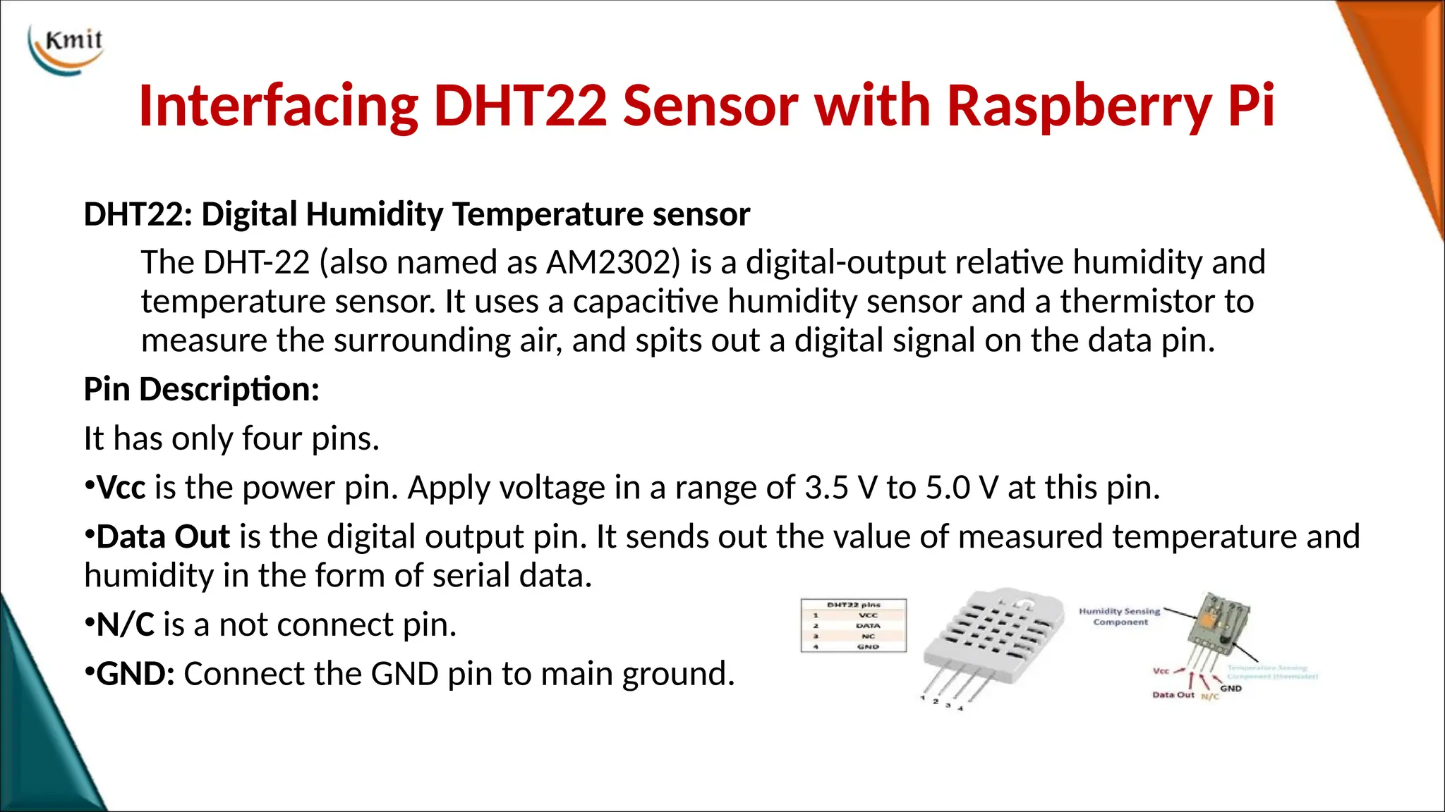
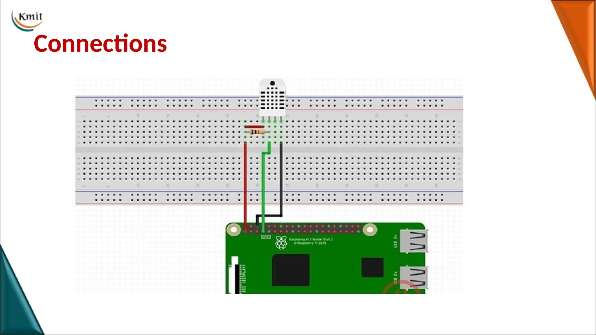
Interfacing DHT22 Sensorwith Raspberry Pi
DHT22: Digital Humidity Temperature sensor
The DHT-22 (also named as AM2302) is a digital-output relative humidity and
temperature sensor. It uses a capacitive humidity sensor and a thermistor to
measure the surrounding air, and spits out a digital signal on the data pin.
Pin Description:
It has only four pins.
•Vcc is the power pin. Apply voltage in a range of 3.5 V to 5.0 V at this pin.
•Data Out is the digital output pin. It sends out the value of measured temperature and
humidity in the form of serial data.
•N/C is a not connect pin.
•GND: Connect the GND pin to main ground.
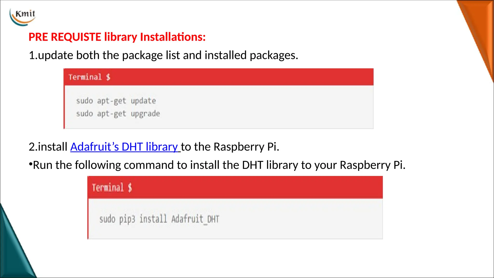
PRE REQUISTE libraryInstallations:
1.update both the package list and installed packages.
2.install Adafruit’s DHT library to the Raspberry Pi.
•Run the following command to install the DHT library to your Raspberry Pi.
64.
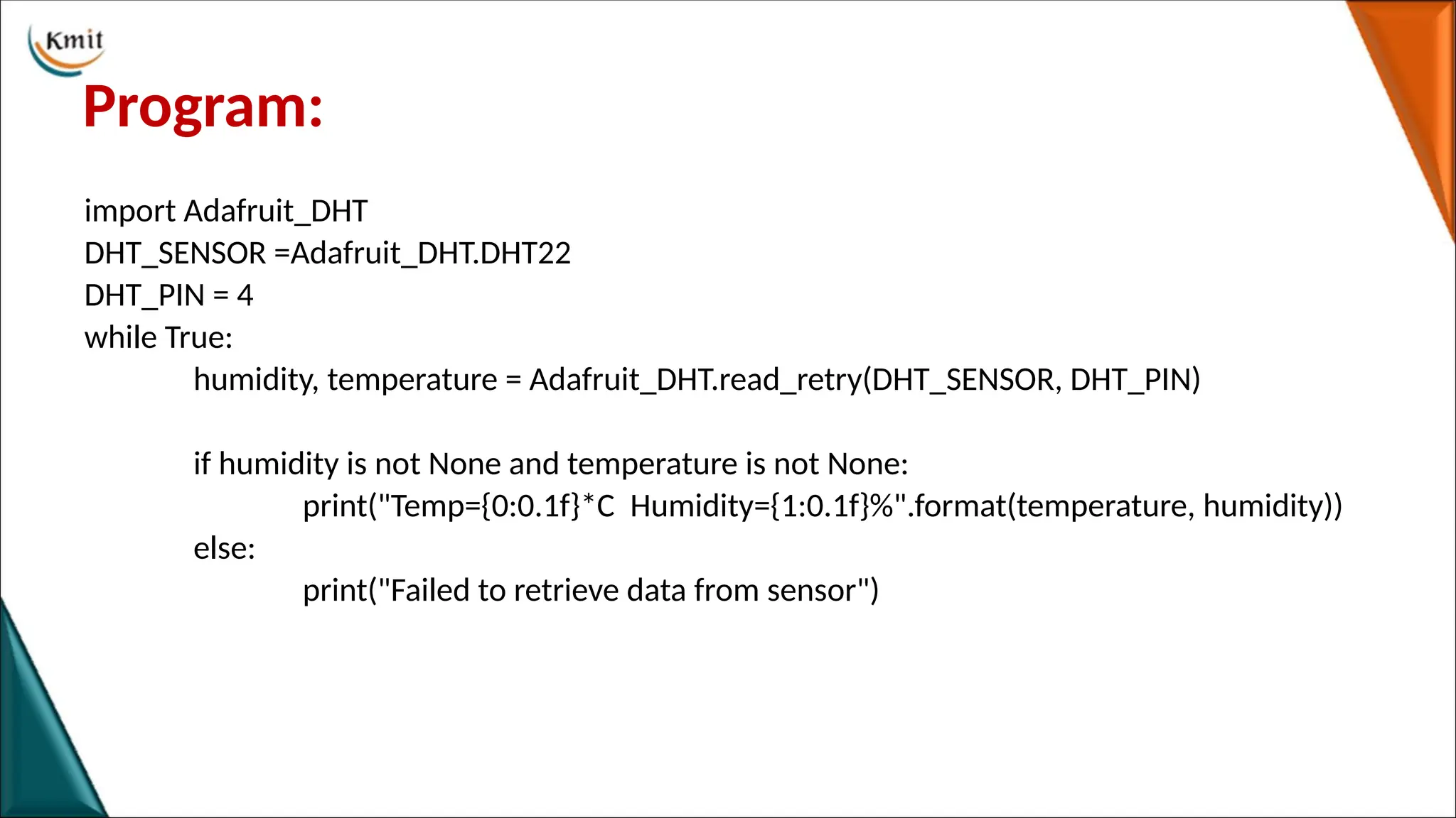
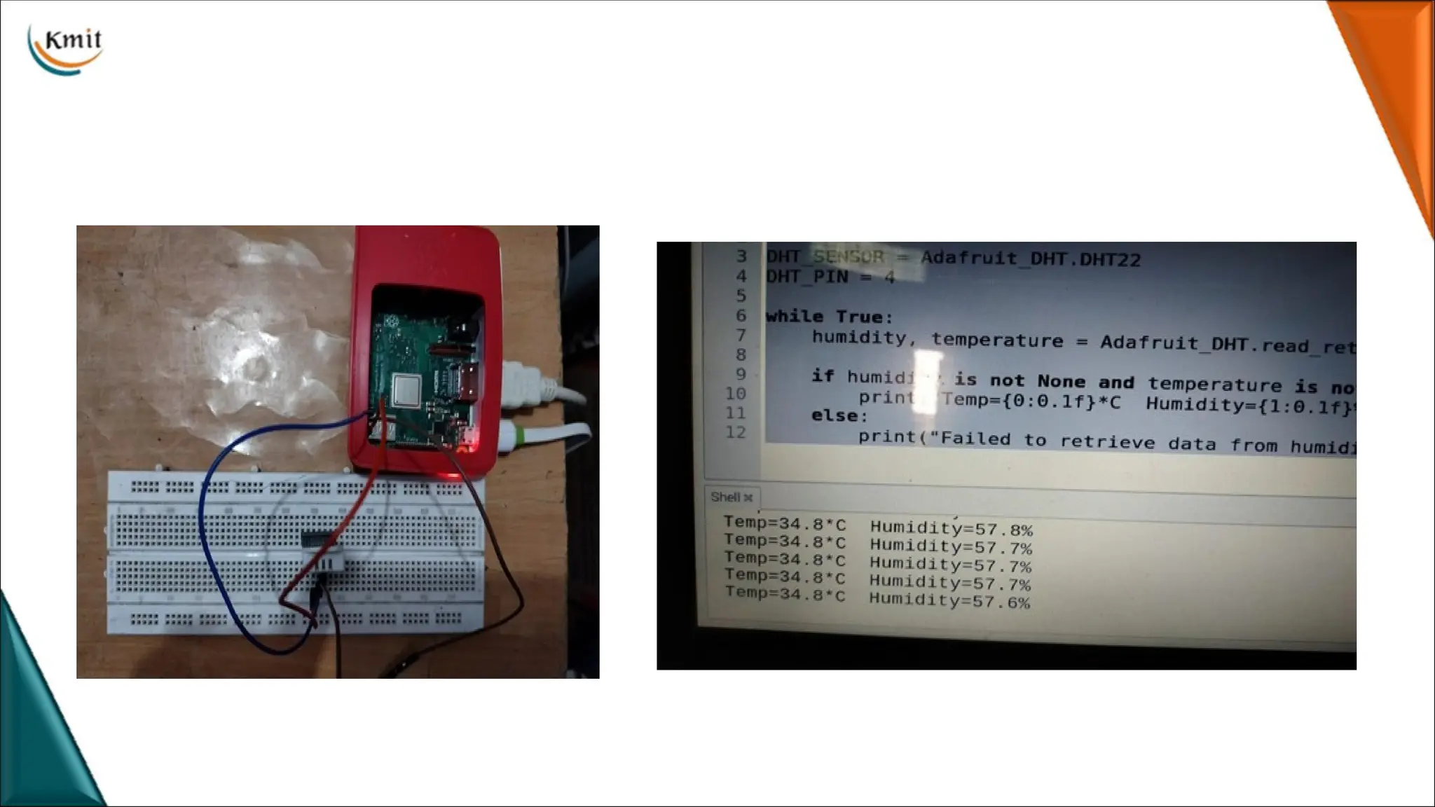
Program:
import Adafruit_DHT
DHT_SENSOR =Adafruit_DHT.DHT22
DHT_PIN= 4
while True:
humidity, temperature = Adafruit_DHT.read_retry(DHT_SENSOR, DHT_PIN)
if humidity is not None and temperature is not None:
print("Temp={0:0.1f}*C Humidity={1:0.1f}%".format(temperature, humidity))
else:
print("Failed to retrieve data from sensor")
66.
Interfacing PI camerawith Raspberry Pi
PI camera
• The Pi camera module is a portable light weight camera that supports
Raspberry Pi. It communicates with Pi using the MIPI camera serial interface
protocol. It is normally used in image processing, machine learning or in
surveillance projects.
• Pi Camera module can be used to take pictures and high definition video.
Raspberry Pi Board has CSI (Camera Serial Interface) interface to which we
can attach Pi Camera module directly using 15-pin ribbon cable.
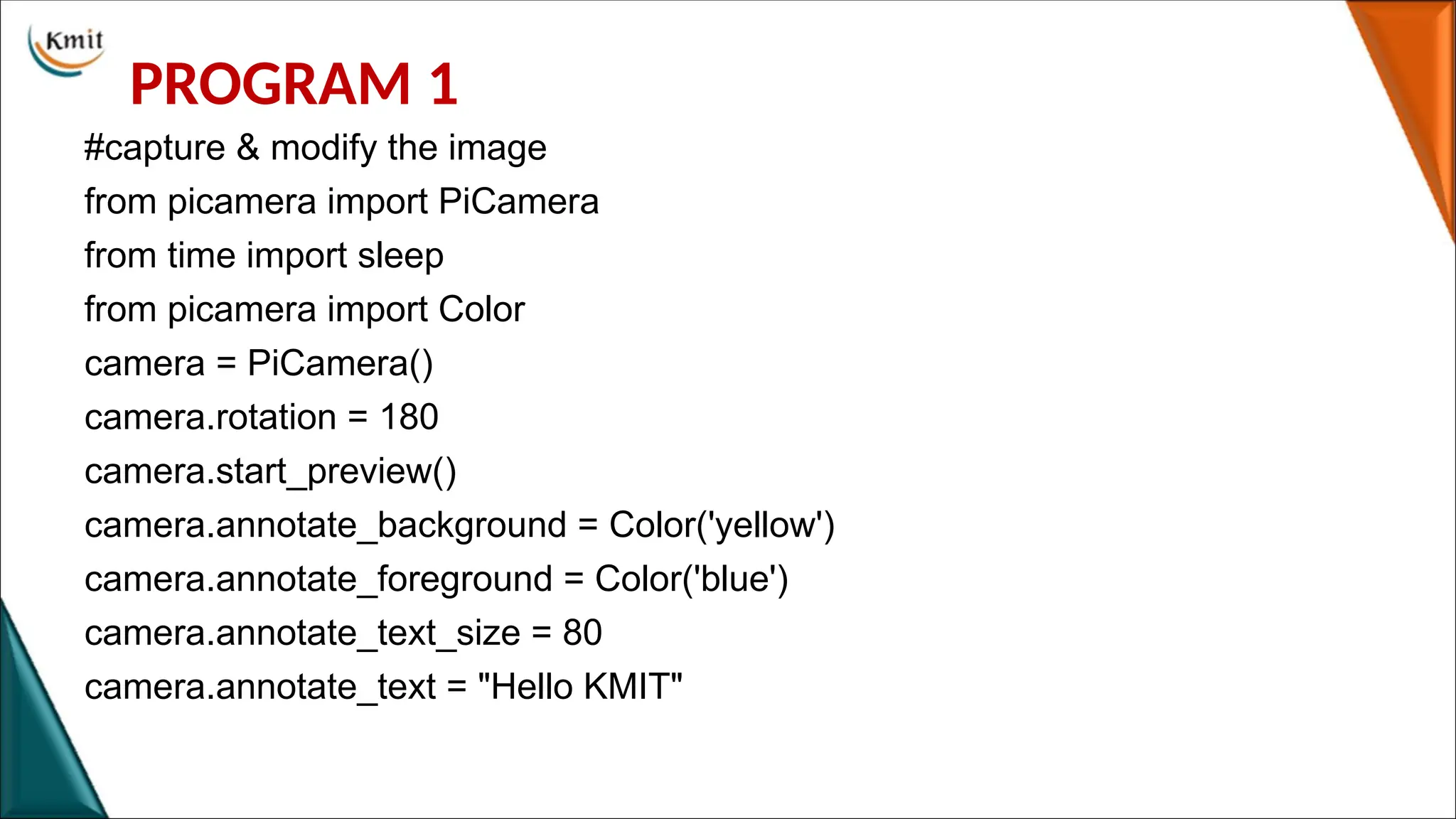
PROGRAM 1
#capture &modify the image
from picamera import PiCamera
from time import sleep
from picamera import Color
camera = PiCamera()
camera.rotation = 180
camera.start_preview()
camera.annotate_background = Color('yellow')
camera.annotate_foreground = Color('blue')
camera.annotate_text_size = 80
camera.annotate_text = "Hello KMIT"
69.
for i inrange(5): sleep(5)
camera.capture('/home/pi/Desktop/Rasp1%s.jpg' % i)
camera.stop_preview()
70.
PROGRAM 2
#video saving
frompicamera import PiCamera
from time import sleep
from picamera import PiCamera, Color
camera = PiCamera()
camera.rotation = 180
camera.start_preview()
camera.annotate_background = Color('yellow')
camera.annotate_foreground = Color('blue')
camera.annotate_text_size = 80
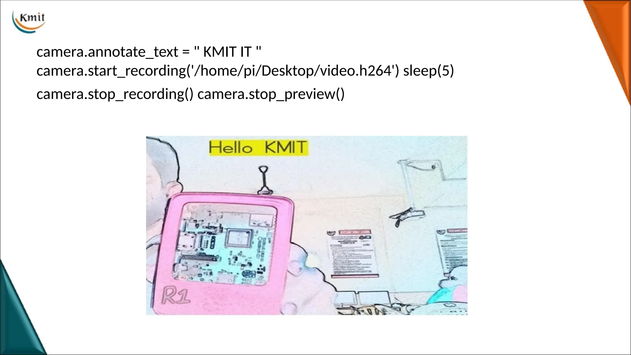
71.
camera.annotate_text = "KMIT IT "
camera.start_recording('/home/pi/Desktop/video.h264') sleep(5)
camera.stop_recording() camera.stop_preview()