Download to read offline
![International Research Journal of Engineering and Technology (IRJET) e-ISSN: 2395-0056
Volume: 04 Issue: 07 | July -2017 www.irjet.net p-ISSN: 2395-0072
© 2017, IRJET | Impact Factor value: 5.181 | ISO 9001:2008 Certified Journal | Page 54
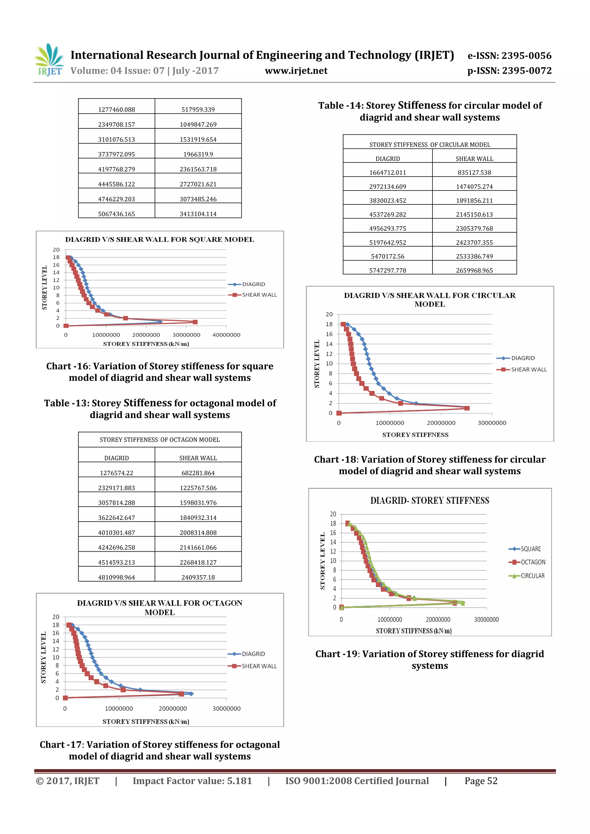
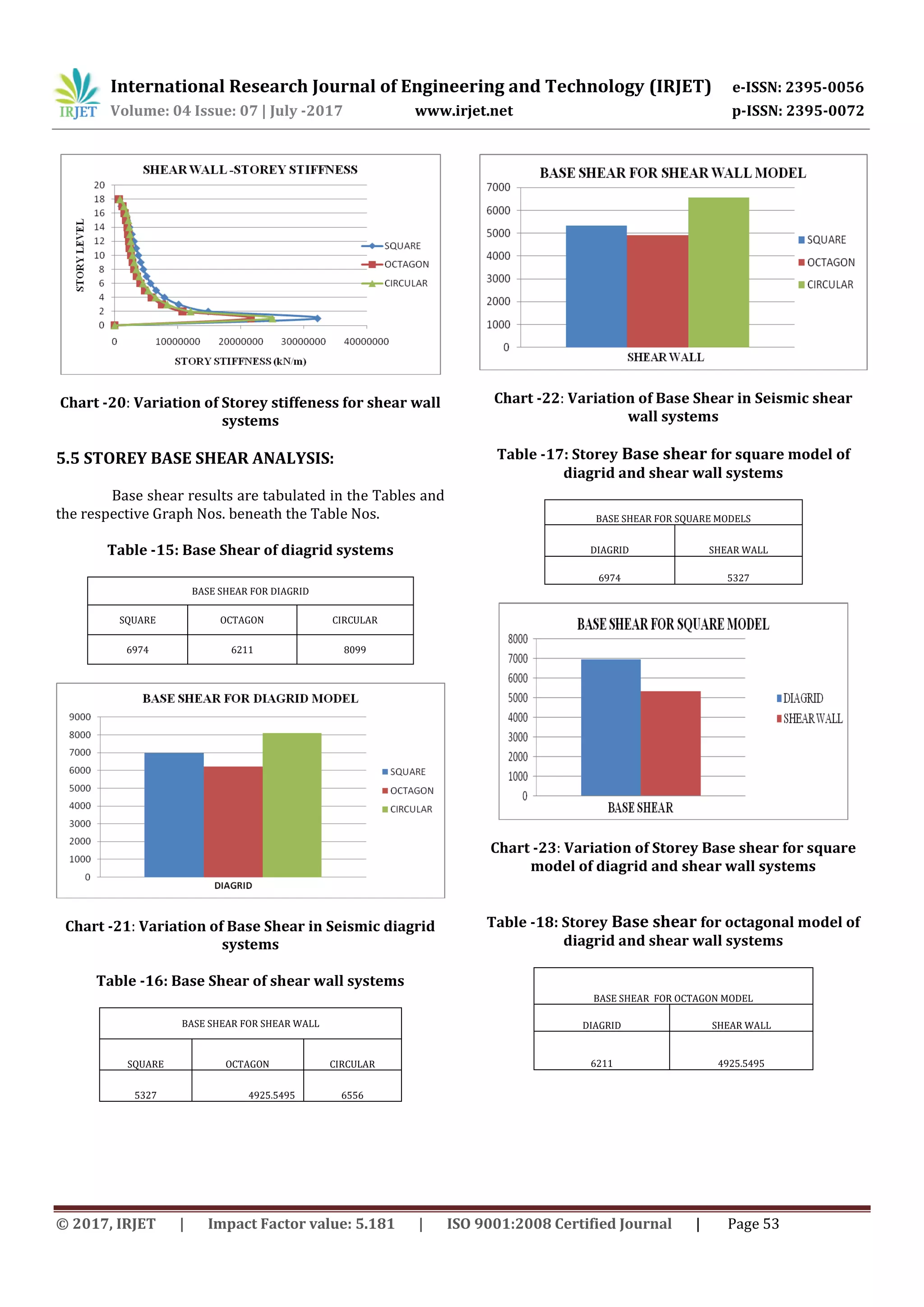
Chart -24: Variation of Base Shear for octagonal model
of diagrid and shear wall systems
Table -19: Storey Base shear for circular model of
diagrid and shear wall systems
BASE SHEAR FOR CIRCULAR MODEL
DIAGRID SHEAR WALL
8099 6556
Chart -25: Variation of Base Shear for circular model
of diagrid and shear wall systems
6. CONCLUSIONS
The introduction of diagrid systems in tall
structures is found to increase the seismic
performance of the structure.
From the comparison of diagrid system with shear
wall system it is found that the lateral
displacements in diagrid models are much lesser
than the shear wall models.
The lesser lateral displacements in diagrid shows
the enhanced resistance of the buildings against
lateral seismic force.
The storey drifts is also smaller value in model with
diagrid system than shear wall system. Thus the
diagonal elements ofthediagrideffectivelycounter
the drifts from earthquake forces.
The stiffness values of the diagrid models are also
comparatively higher than the shear wall models.
The diagrid models are stiff against vibrations due
to seismic forces than the shear wall models.
The base shear values in diagrid models are higher
than other models with shows higher seismic
forces are acting on the diagrid models.
The time periods are less in diagrid system models.
lesser values of the time period than shear wall
models shows that diagrid models are less flexible
against seismic vibrations.
REFERENCES
[1] Khalid K. Shadhan “Optimal diagrid angle to minimize
drift in high-rise steel buildings subjected to wind
loads”,International Journal of Civil Engineering and
Technology (IJCIET),Volume 6, Issue 11, Nov 2015, pp.
01-10
[2] Lekshmi Mohan1, C.K.Prasad Varma Thampan2,
“Numerical Modelling and Evaluation of Hybrid Diagrid
Structures” International Journal of Research in Advent
Technology (E-ISSN: 2321-9637),“TASC-15”,June2015
pp10-11.
[3] Raghunath .D. Deshpande1, Sadanand M. Patil2,
Subramanya Ratan3 “Analysis and comparisonofdiagrid
and conventional structural system” IRJET, Volume: 02
Issue: 03 June -2015.
[4] Harish Varsani 1, Narendra Pokar 2, Dipesh Gandhi3
“Comparative Analysis of Diagrid Structural System and
Conventional Structural System for High Rise Steel
Building” IJAREST ISSN(O):2393-9877, ISSN(P): 2394-
2444,Volume 2,Issue 1, January- 2015..
[5] Nishith B. Panchal, Dr. V. R. Patel, Dr. I. I. Pandya,
“Optimum Angle of Diagrid Structural System”
IETR,ISSN: 2321-0869, Volume-2, Issue-6, June 2014
BIOGRAPHIES
Pavana v pursuing his M.Tech. in
Civil Strutures from Government
Engineering College, Haveri &
obtained B.E. Civil from BIT
Bangalore.
Dr. Shreepad Desai presently
working as Asst. Professor in
Government Engineering College,
Haveri. He has obtained his PhD
from VTU Belagavi. M.Tech from
M.C.E Hasan & obtained B.E. Civil
Engineering from S.D.M College of
Engineering and Technology,
Dharwad.](https://image.slidesharecdn.com/irjet-v4i808-170915105624/75/Performance-Analysis-of-the-Tall-Structure-with-Diagrid-for-Seismic-Loading-11-2048.jpg)


![International Research Journal of Engineering and Technology (IRJET) e-ISSN: 2395-0056
Volume: 04 Issue: 07 | July -2017 www.irjet.net p-ISSN: 2395-0072
© 2017, IRJET | Impact Factor value: 5.181 | ISO 9001:2008 Certified Journal | Page 54
Chart -24: Variation of Base Shear for octagonal model
of diagrid and shear wall systems
Table -19: Storey Base shear for circular model of
diagrid and shear wall systems
BASE SHEAR FOR CIRCULAR MODEL
DIAGRID SHEAR WALL
8099 6556
Chart -25: Variation of Base Shear for circular model
of diagrid and shear wall systems
6. CONCLUSIONS
The introduction of diagrid systems in tall
structures is found to increase the seismic
performance of the structure.
From the comparison of diagrid system with shear
wall system it is found that the lateral
displacements in diagrid models are much lesser
than the shear wall models.
The lesser lateral displacements in diagrid shows
the enhanced resistance of the buildings against
lateral seismic force.
The storey drifts is also smaller value in model with
diagrid system than shear wall system. Thus the
diagonal elements ofthediagrideffectivelycounter
the drifts from earthquake forces.
The stiffness values of the diagrid models are also
comparatively higher than the shear wall models.
The diagrid models are stiff against vibrations due
to seismic forces than the shear wall models.
The base shear values in diagrid models are higher
than other models with shows higher seismic
forces are acting on the diagrid models.
The time periods are less in diagrid system models.
lesser values of the time period than shear wall
models shows that diagrid models are less flexible
against seismic vibrations.
REFERENCES
[1] Khalid K. Shadhan “Optimal diagrid angle to minimize
drift in high-rise steel buildings subjected to wind
loads”,International Journal of Civil Engineering and
Technology (IJCIET),Volume 6, Issue 11, Nov 2015, pp.
01-10
[2] Lekshmi Mohan1, C.K.Prasad Varma Thampan2,
“Numerical Modelling and Evaluation of Hybrid Diagrid
Structures” International Journal of Research in Advent
Technology (E-ISSN: 2321-9637),“TASC-15”,June2015
pp10-11.
[3] Raghunath .D. Deshpande1, Sadanand M. Patil2,
Subramanya Ratan3 “Analysis and comparisonofdiagrid
and conventional structural system” IRJET, Volume: 02
Issue: 03 June -2015.
[4] Harish Varsani 1, Narendra Pokar 2, Dipesh Gandhi3
“Comparative Analysis of Diagrid Structural System and
Conventional Structural System for High Rise Steel
Building” IJAREST ISSN(O):2393-9877, ISSN(P): 2394-
2444,Volume 2,Issue 1, January- 2015..
[5] Nishith B. Panchal, Dr. V. R. Patel, Dr. I. I. Pandya,
“Optimum Angle of Diagrid Structural System”
IETR,ISSN: 2321-0869, Volume-2, Issue-6, June 2014
BIOGRAPHIES
Pavana v pursuing his M.Tech. in
Civil Strutures from Government
Engineering College, Haveri &
obtained B.E. Civil from BIT
Bangalore.
Dr. Shreepad Desai presently
working as Asst. Professor in
Government Engineering College,
Haveri. He has obtained his PhD
from VTU Belagavi. M.Tech from
M.C.E Hasan & obtained B.E. Civil
Engineering from S.D.M College of
Engineering and Technology,
Dharwad.](https://crownmelresort.com/image.slidesharecdn.com/irjet-v4i808-170915105624/75/Performance-Analysis-of-the-Tall-Structure-with-Diagrid-for-Seismic-Loading-11-2048.jpg)

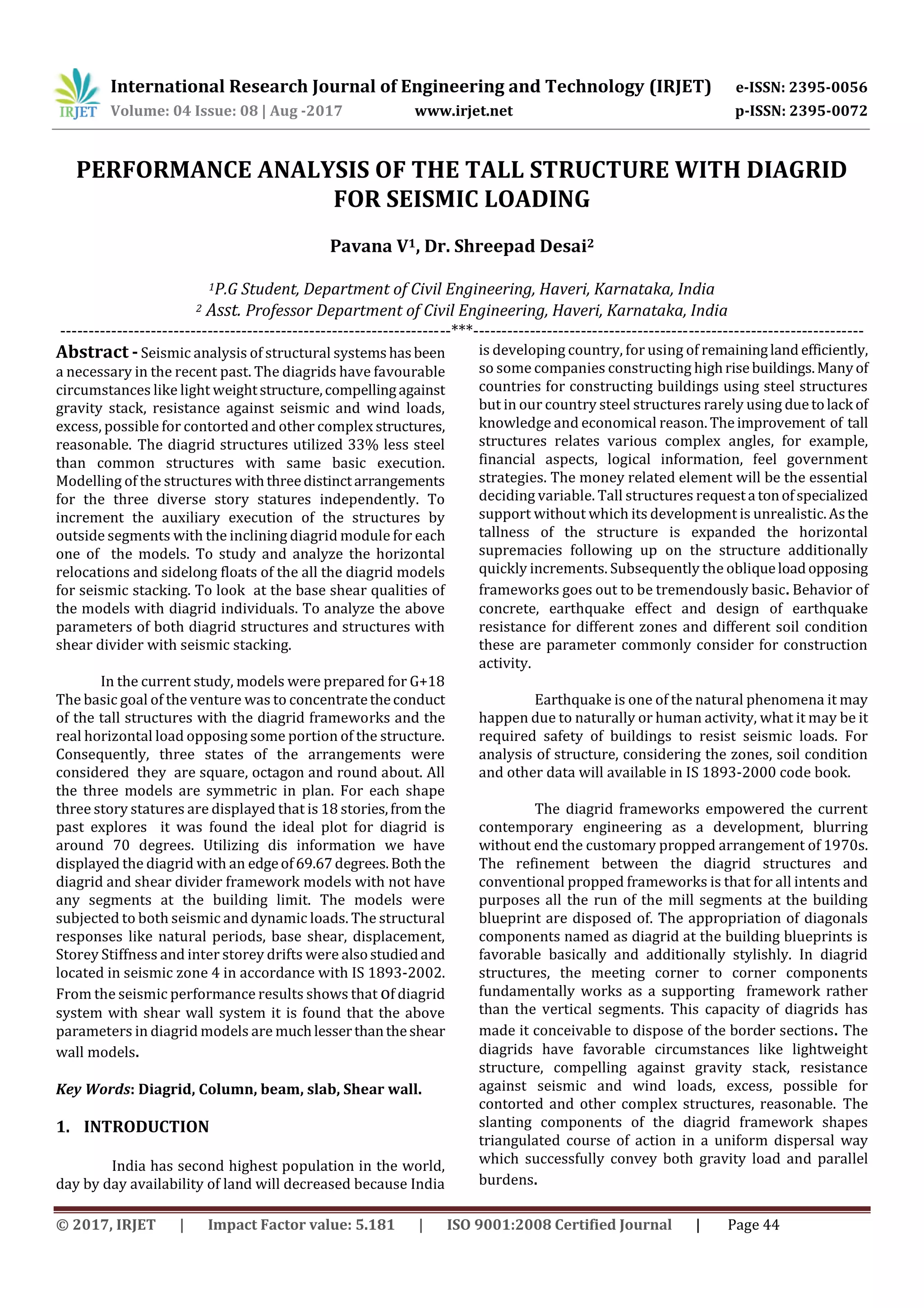
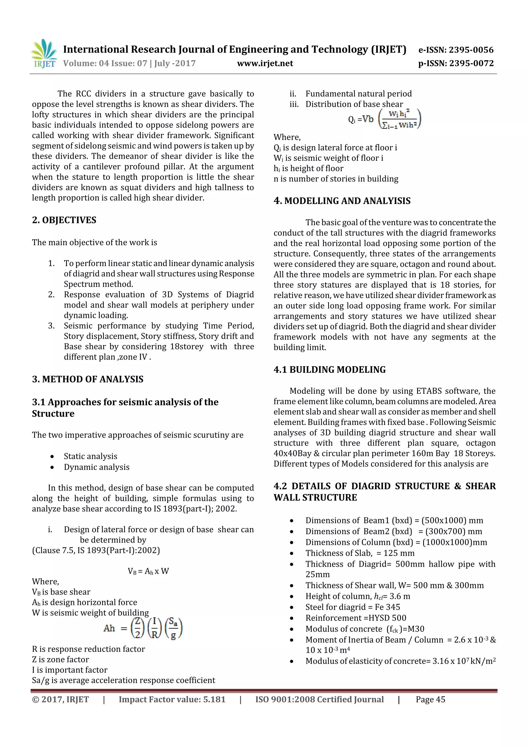
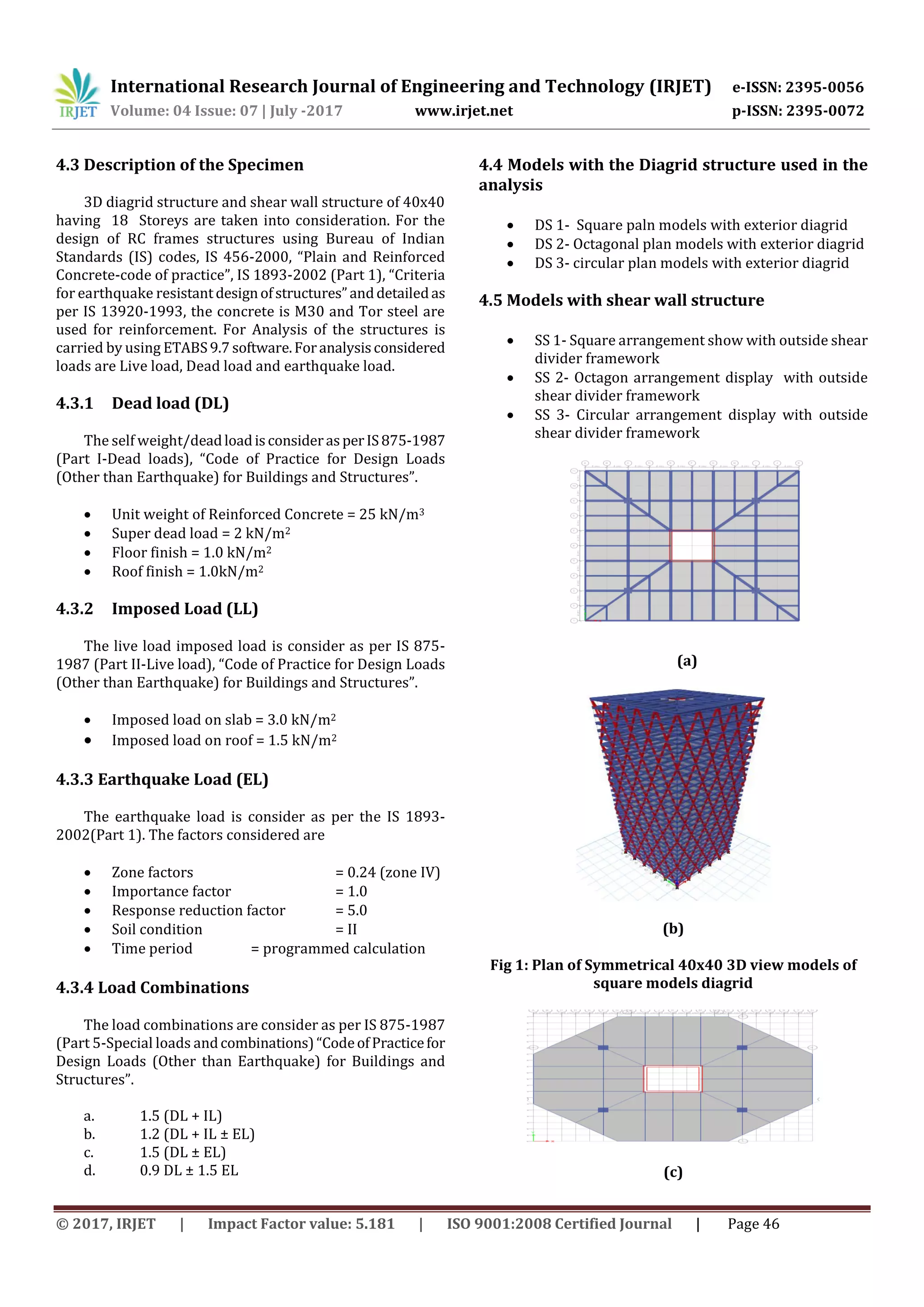
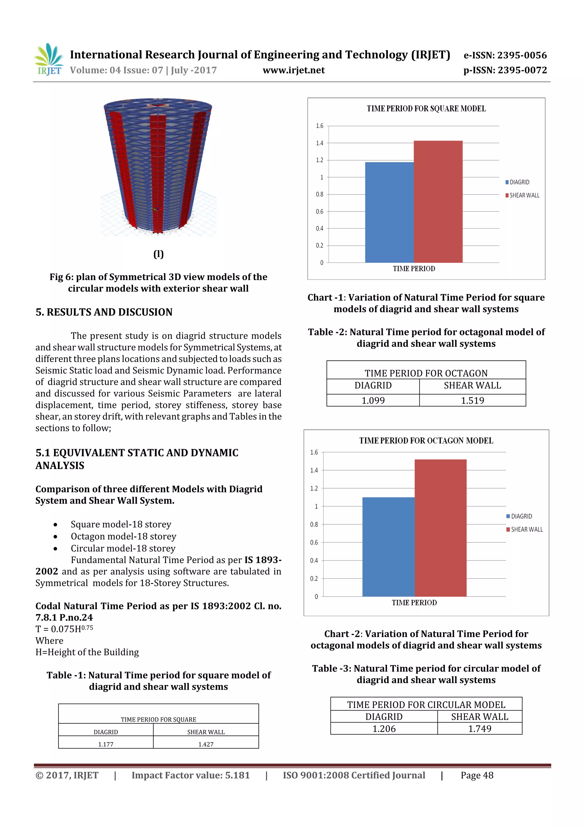
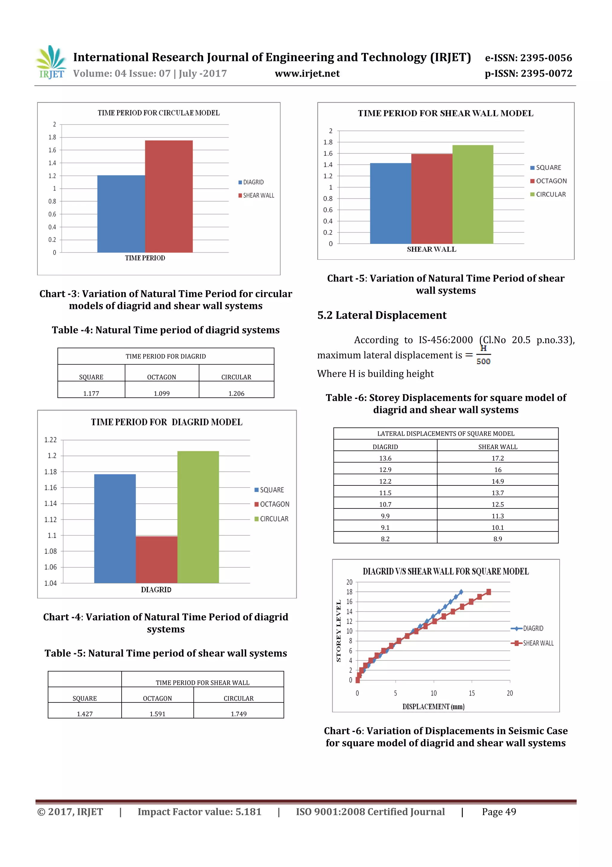
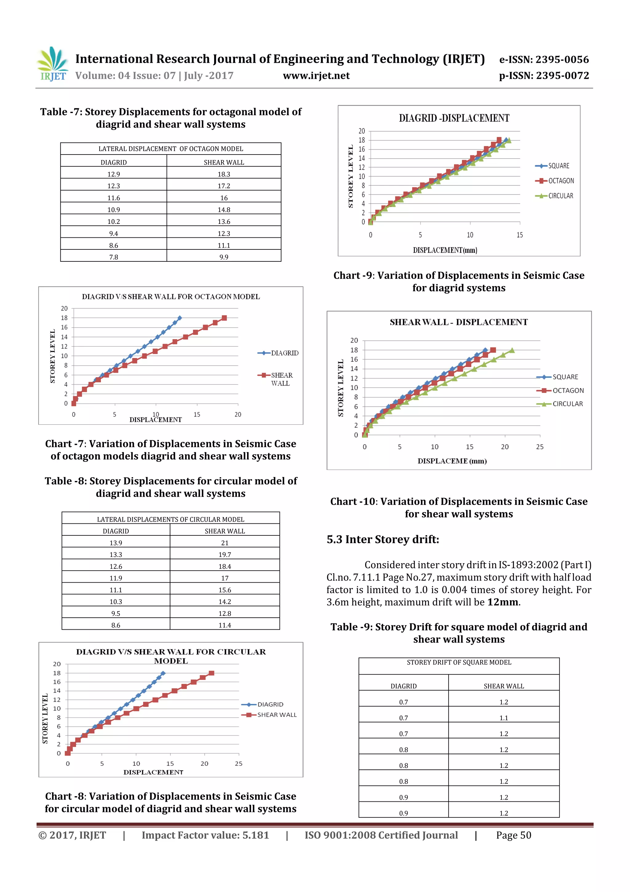
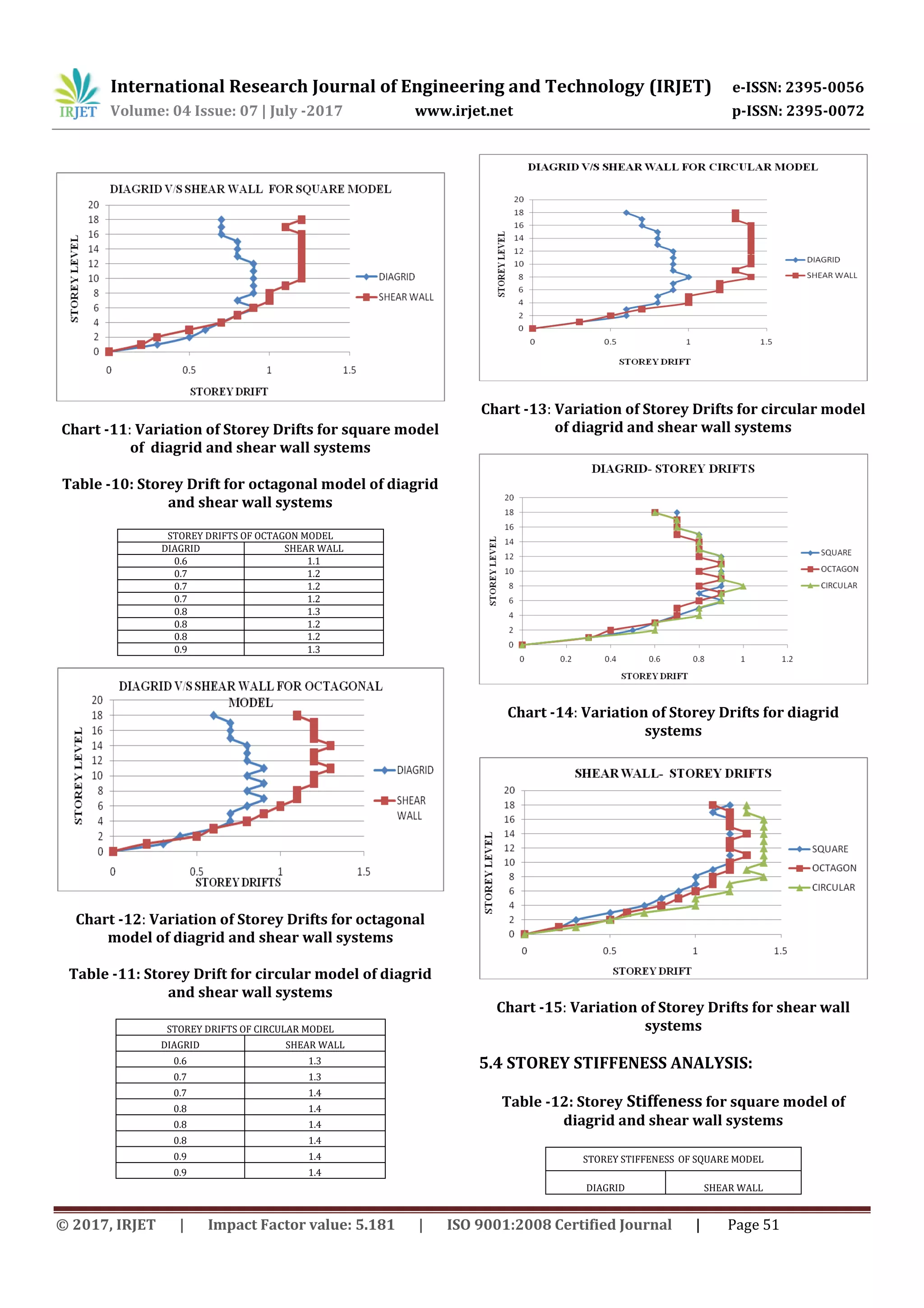
This document analyzes the performance of tall structures with diagrid frameworks under seismic loading. Three 18-story building models are created with square, octagonal, and circular plans using diagrid and shear wall systems. Linear static and dynamic analyses are performed using ETABS software. Results show the diagrid models have shorter natural periods and lower base shear, story displacement, and drift values compared to the equivalent shear wall models, indicating diagrid structures perform better seismically. The study aims to understand how diagrid systems help resist lateral loads in tall buildings.


![presentation]](https://cdn.slidesharecdn.com/ss_thumbnails/e66f3ab5-a49b-471e-8fdf-d93abb012839-160825182707-thumbnail.jpg?width=640&height=640&fit=bounds)


