Downloaded 364 times
![TRAFFIC SIGNAL DESIGN
[IRC 93-1985]](https://image.slidesharecdn.com/ircmethodofsignaldesign-181106111228/75/IRC-Method-of-Signal-Design-1-2048.jpg)


![TRAFFIC SIGNAL DESIGN
[IRC 93-1985]](https://crownmelresort.com/image.slidesharecdn.com/ircmethodofsignaldesign-181106111228/75/IRC-Method-of-Signal-Design-1-2048.jpg)


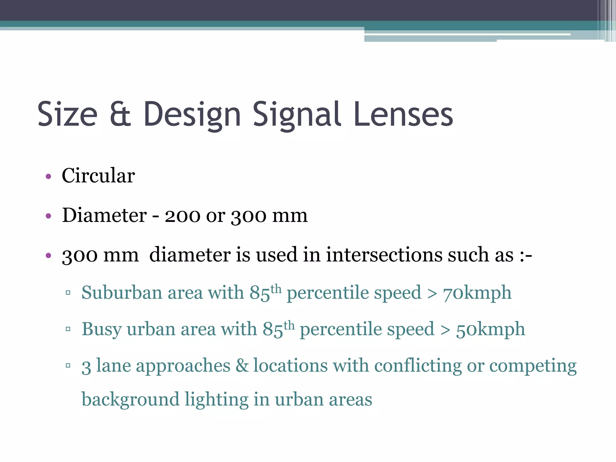
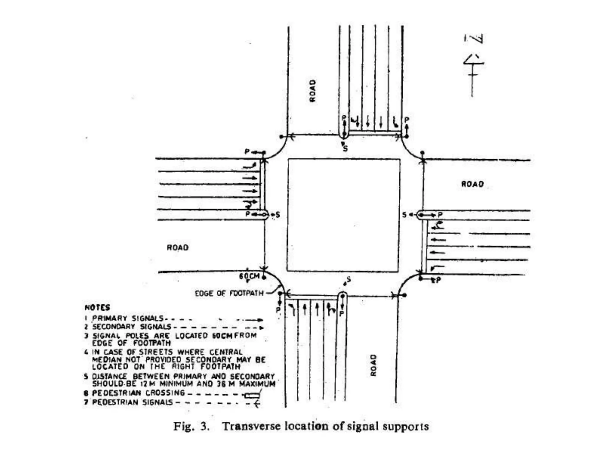
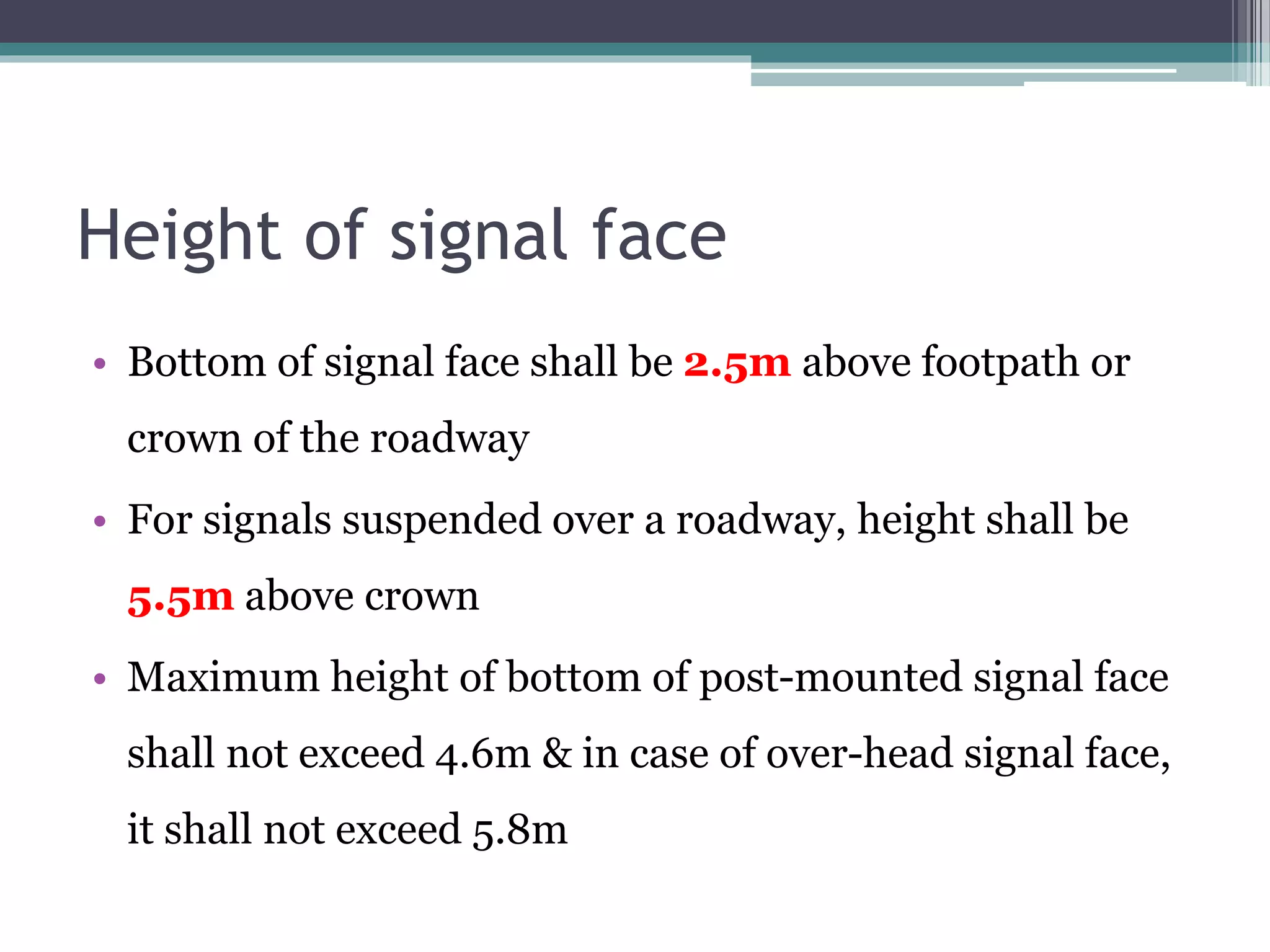
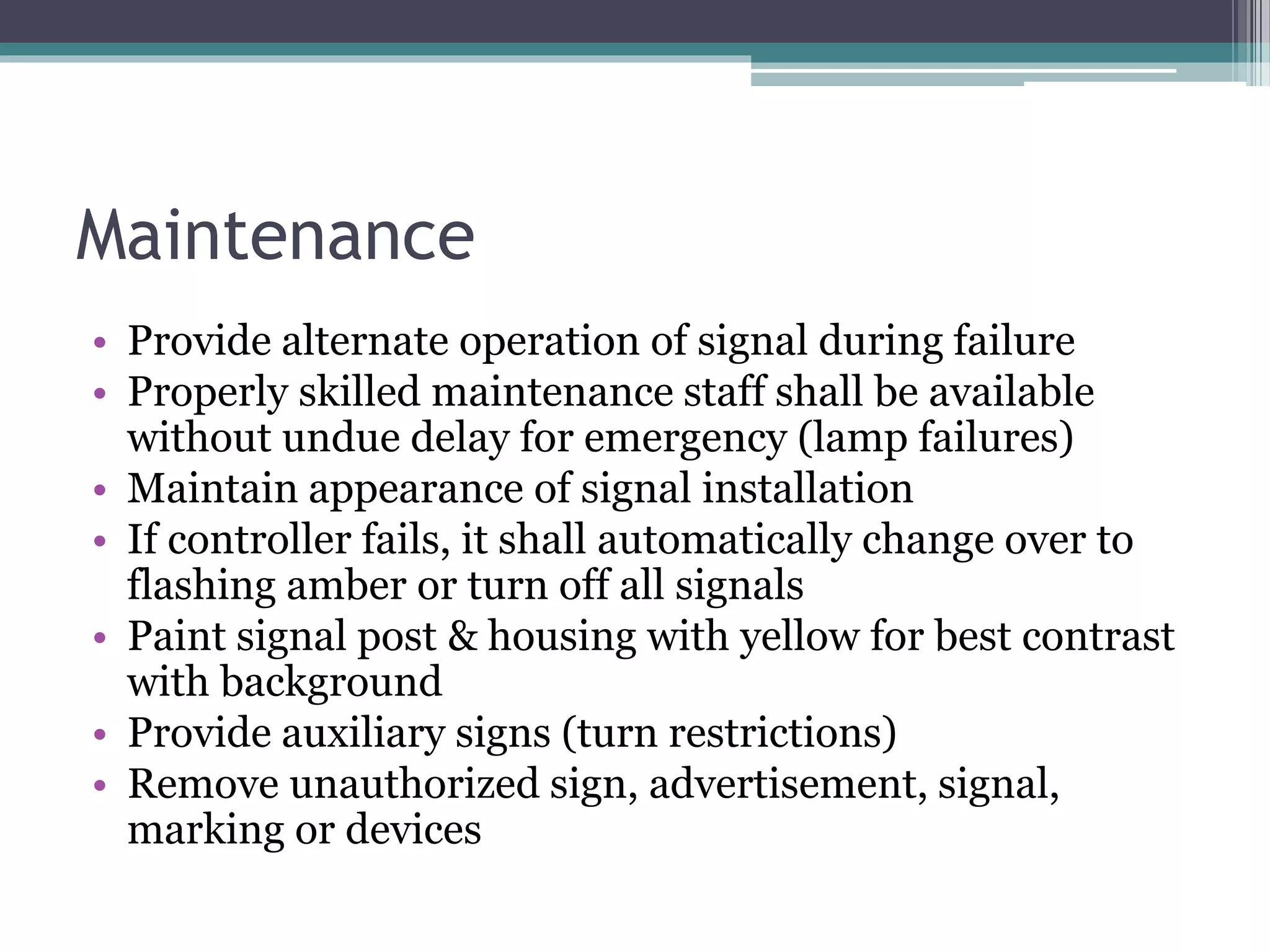
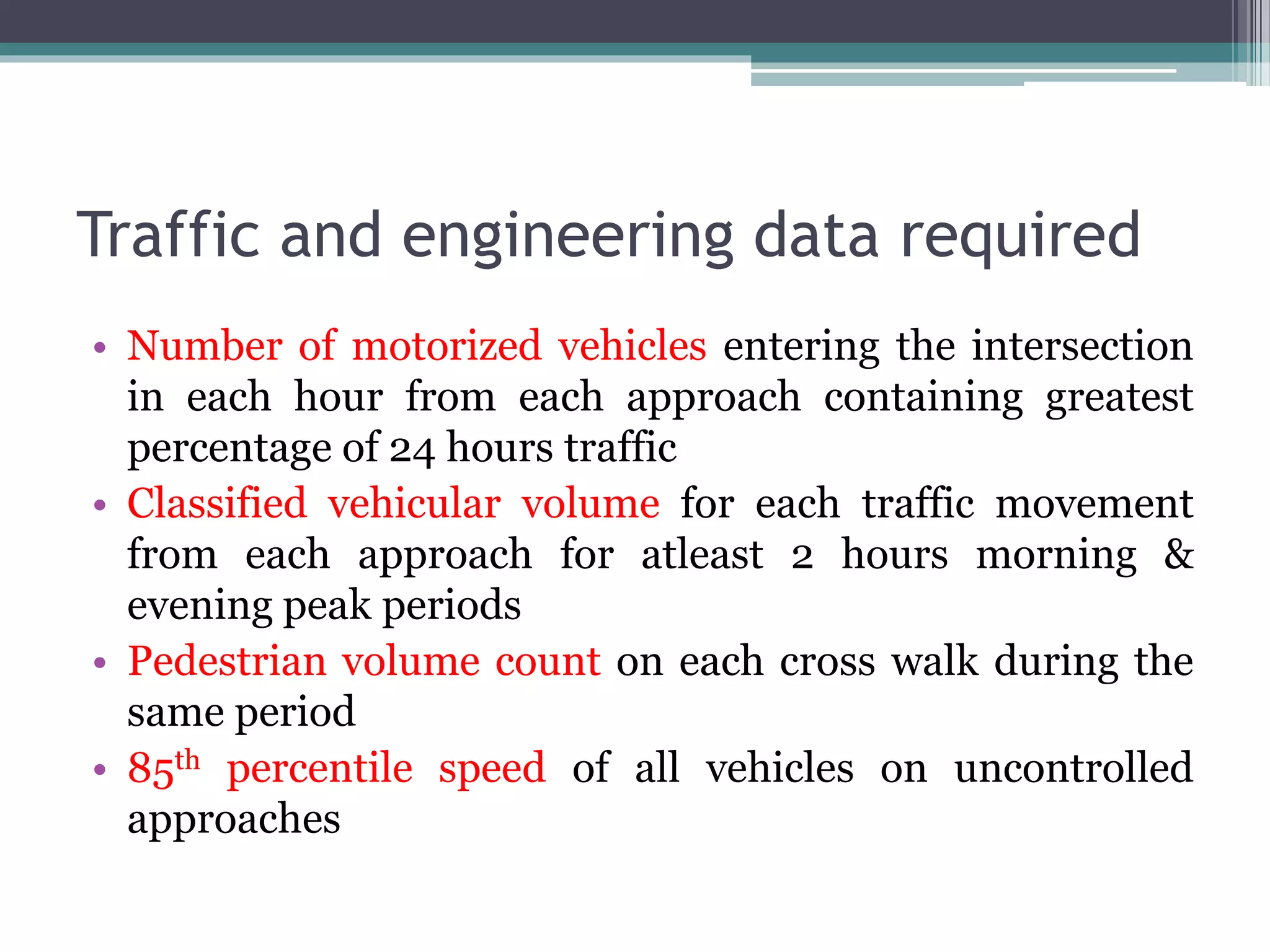
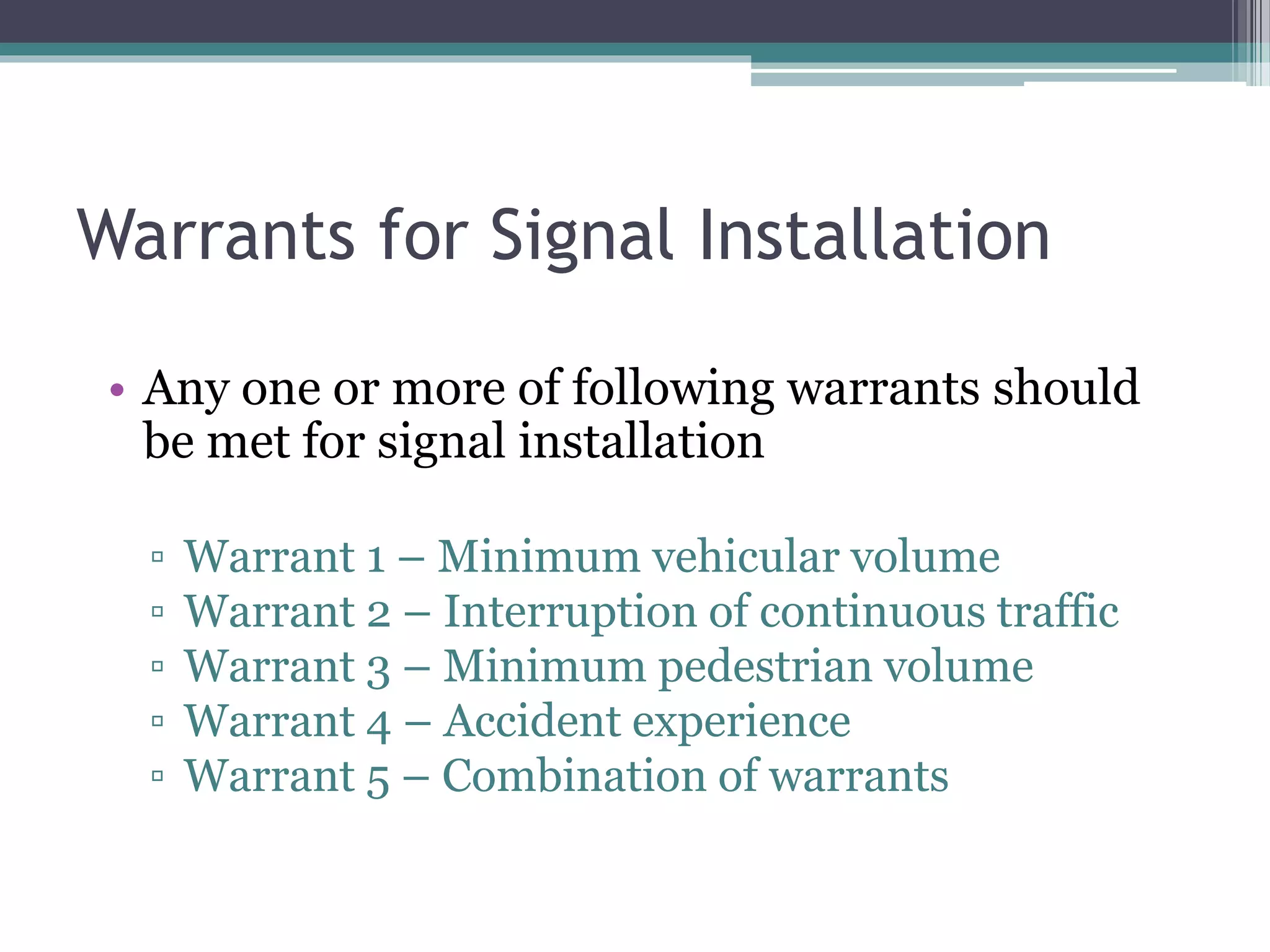
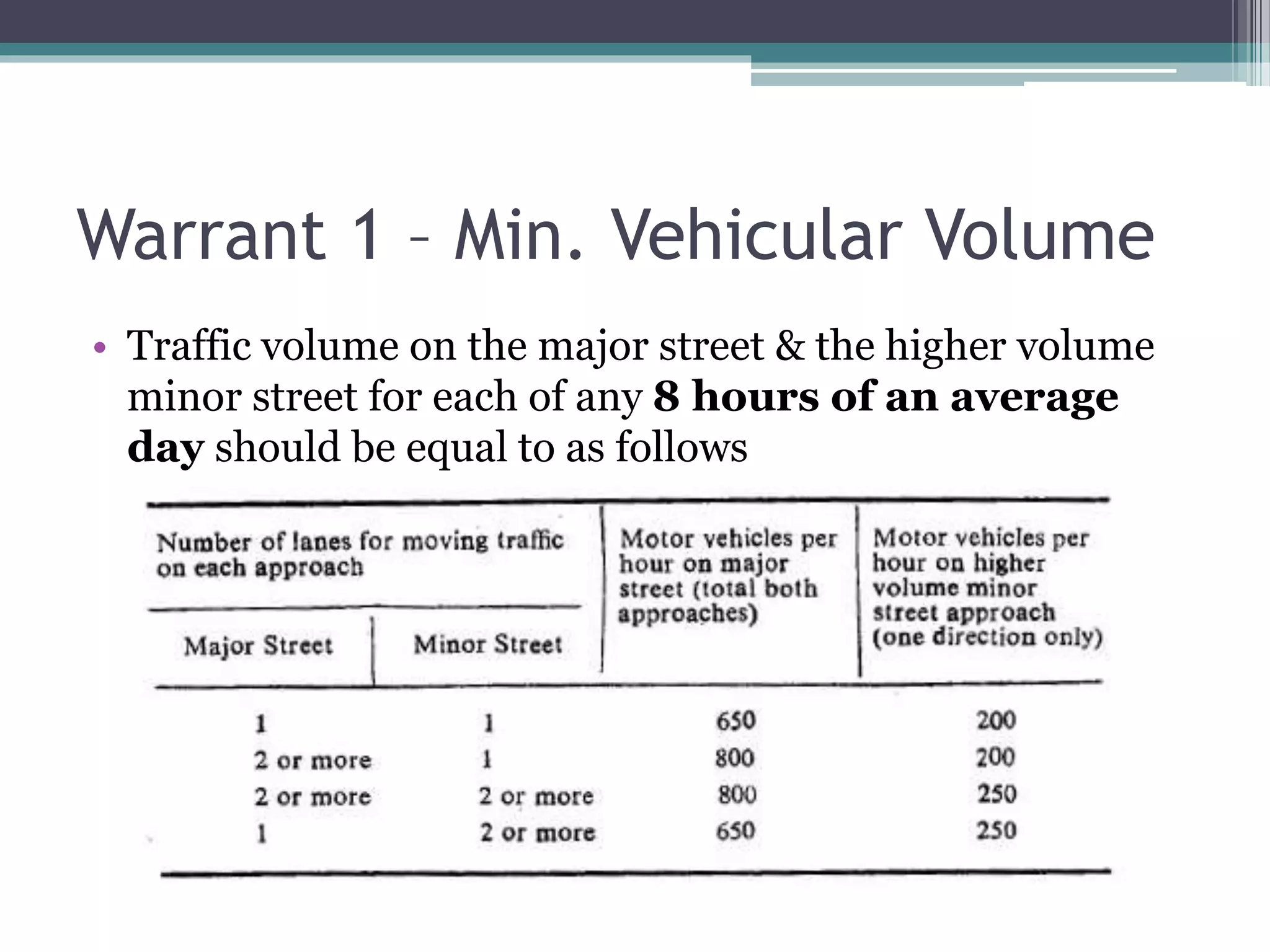
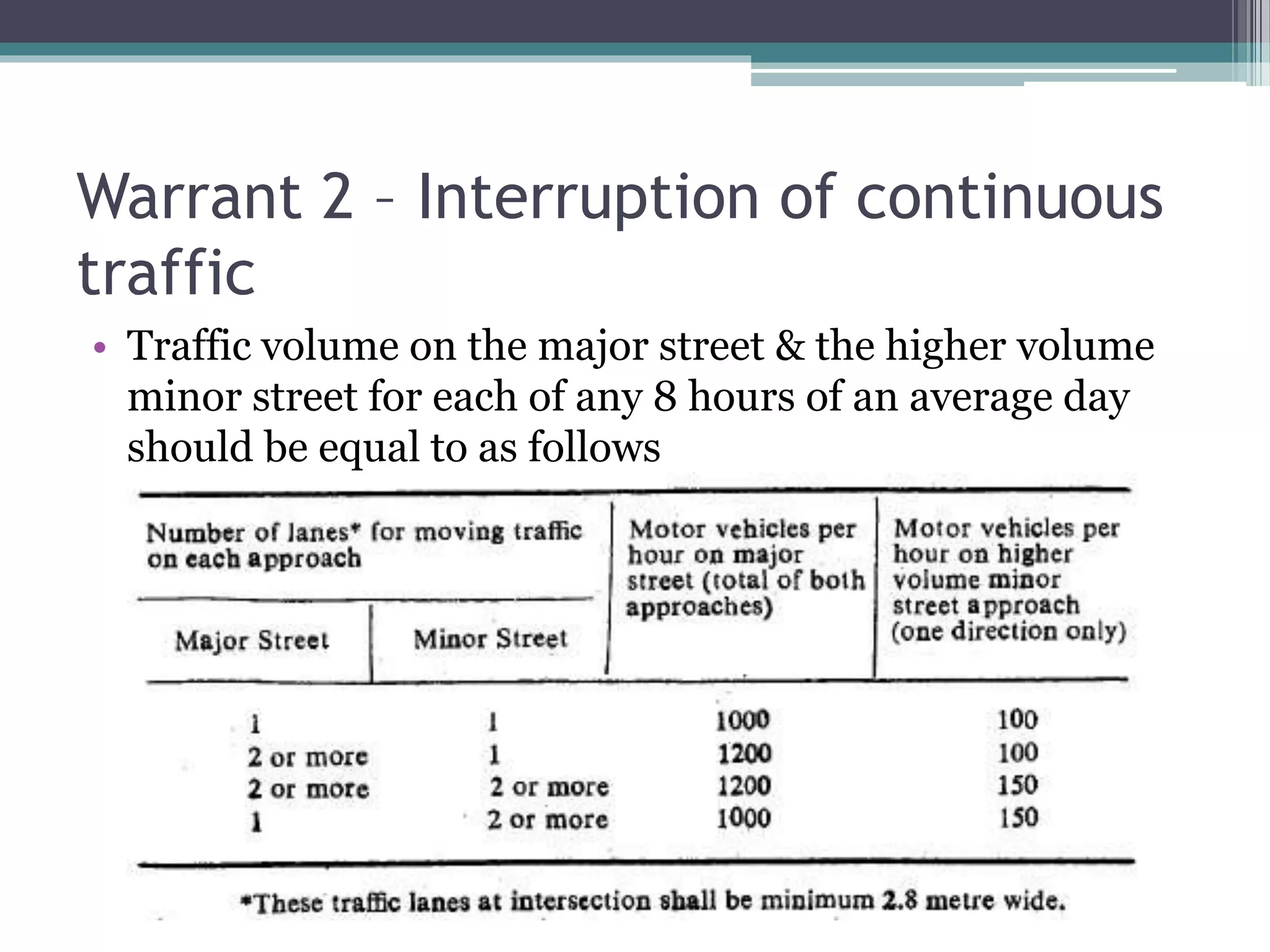
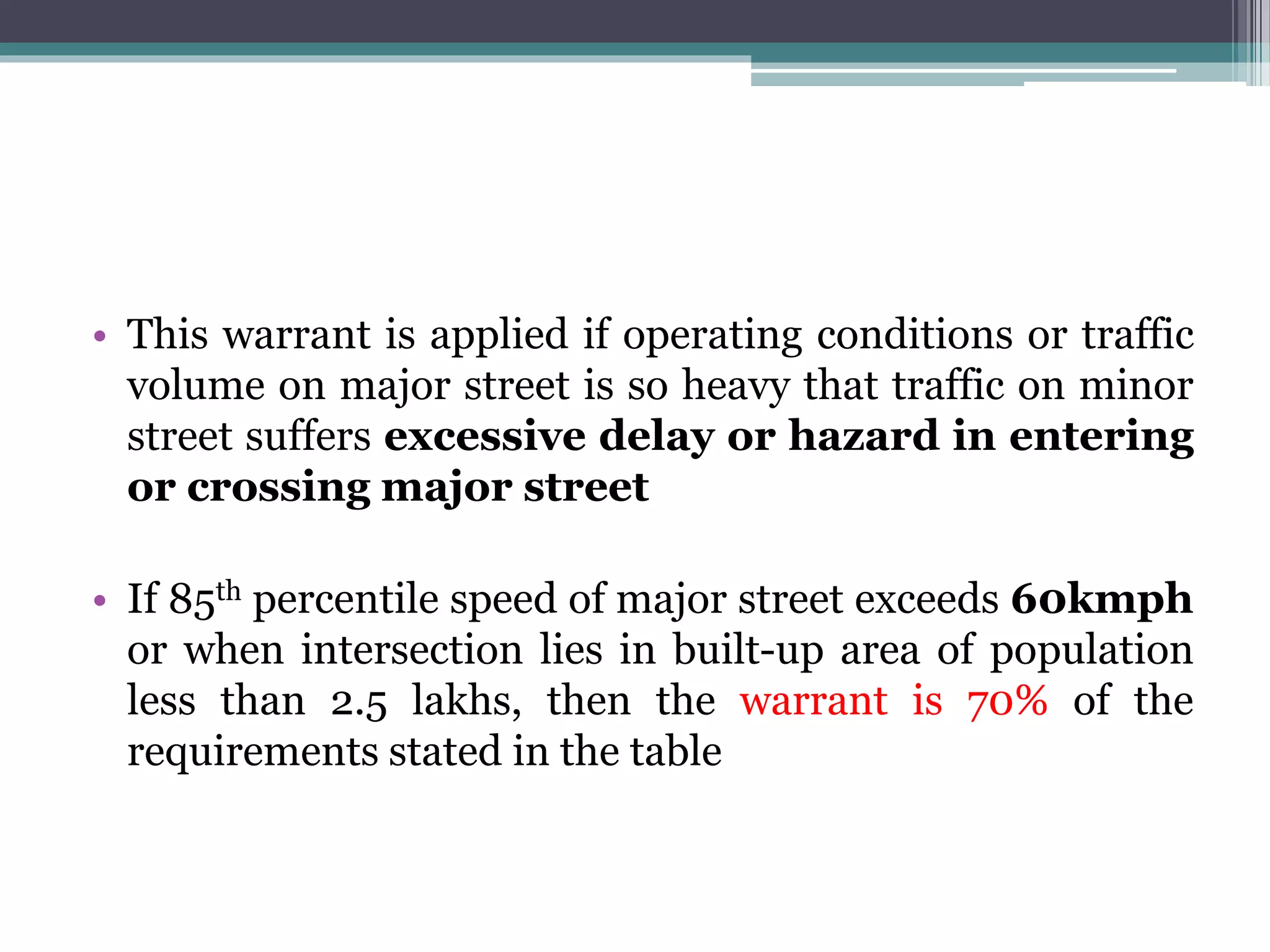
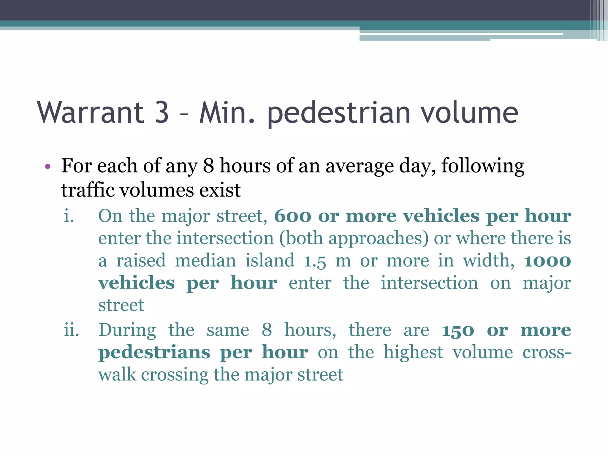
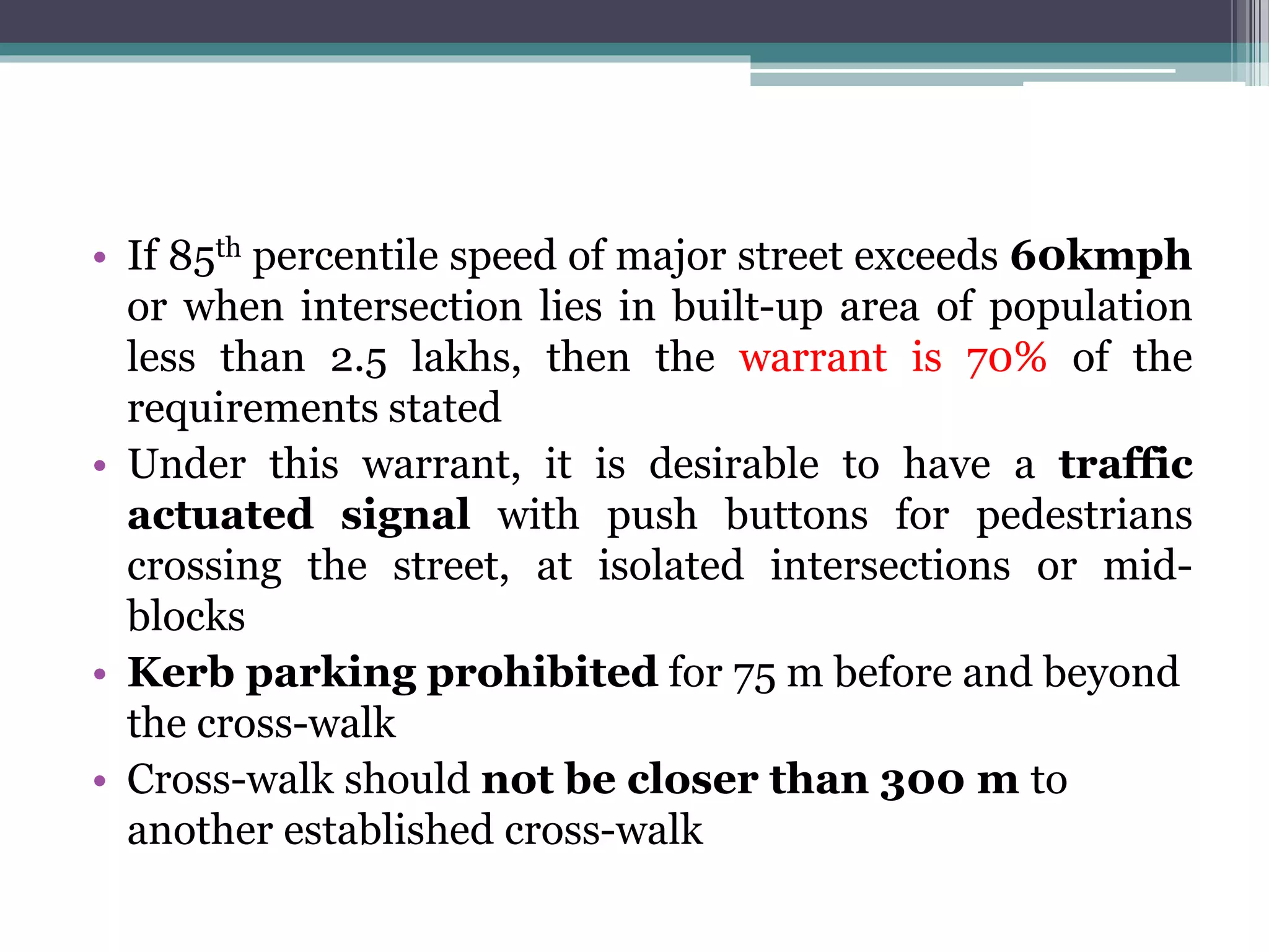
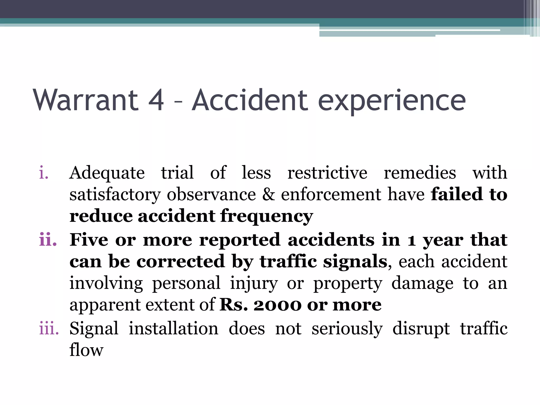
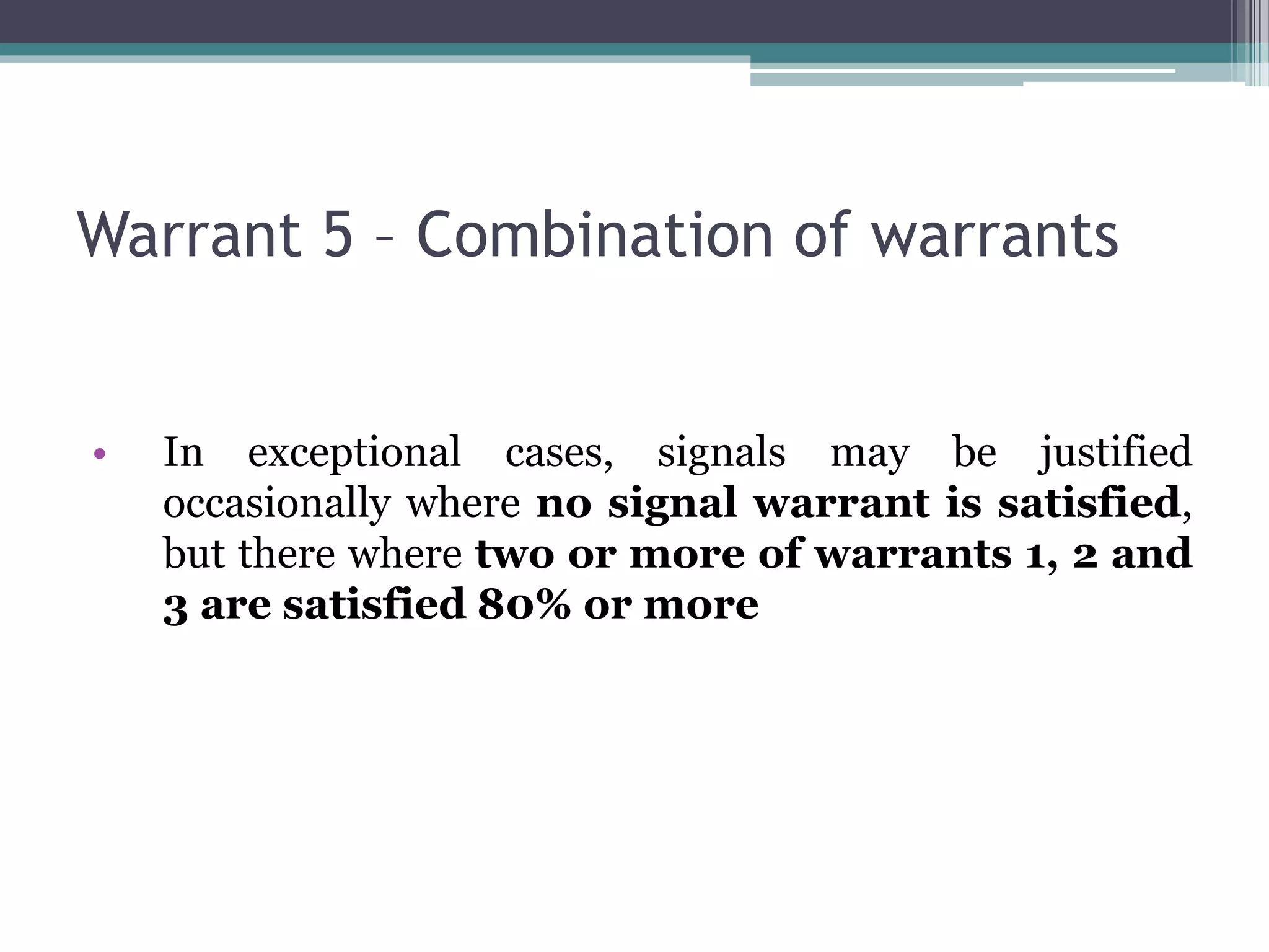
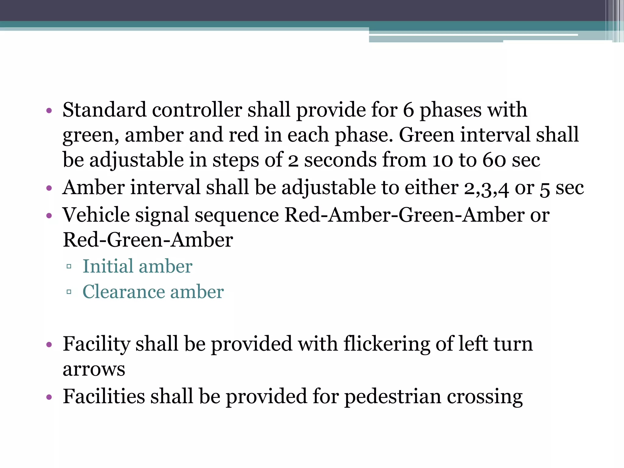
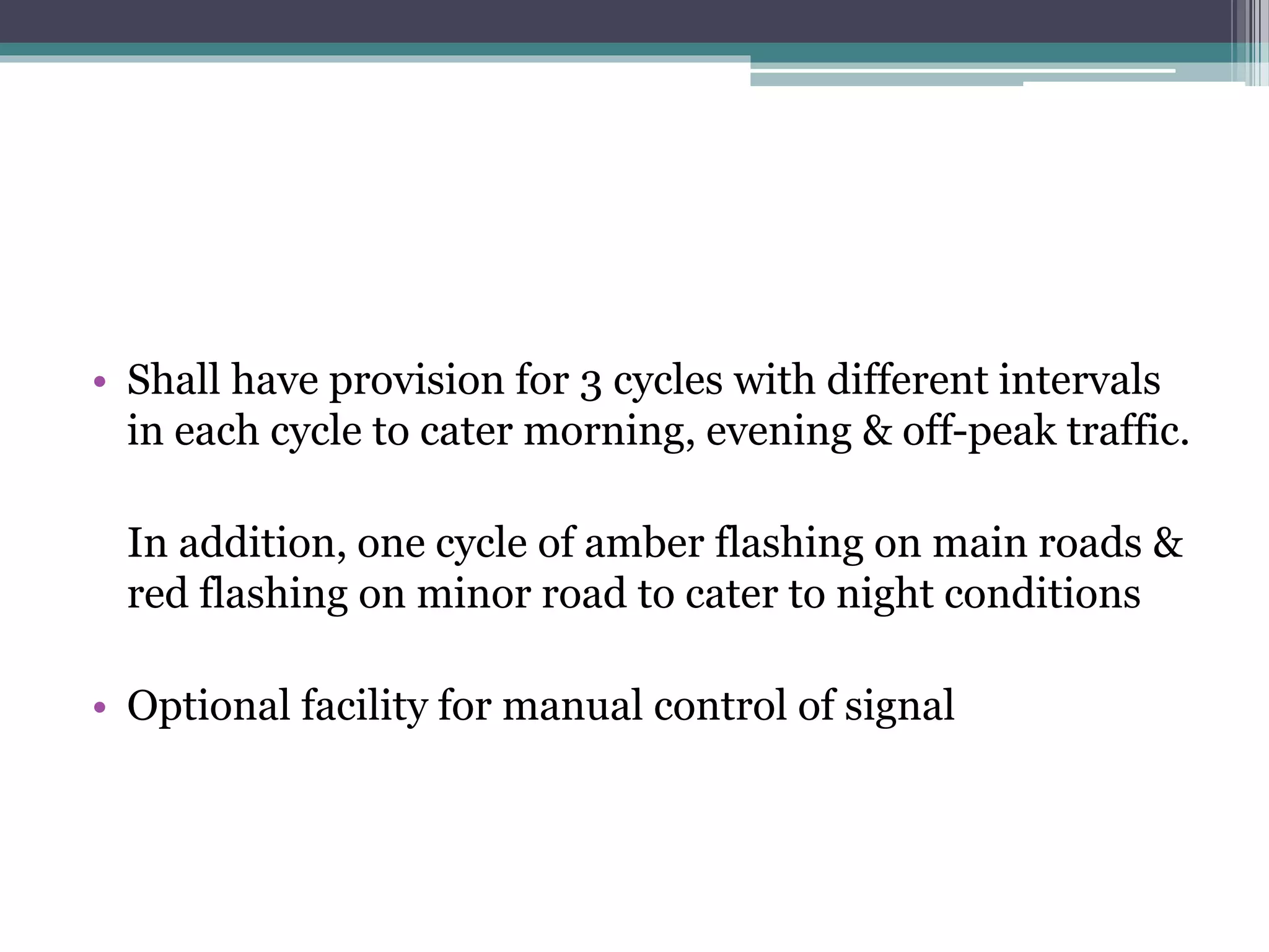
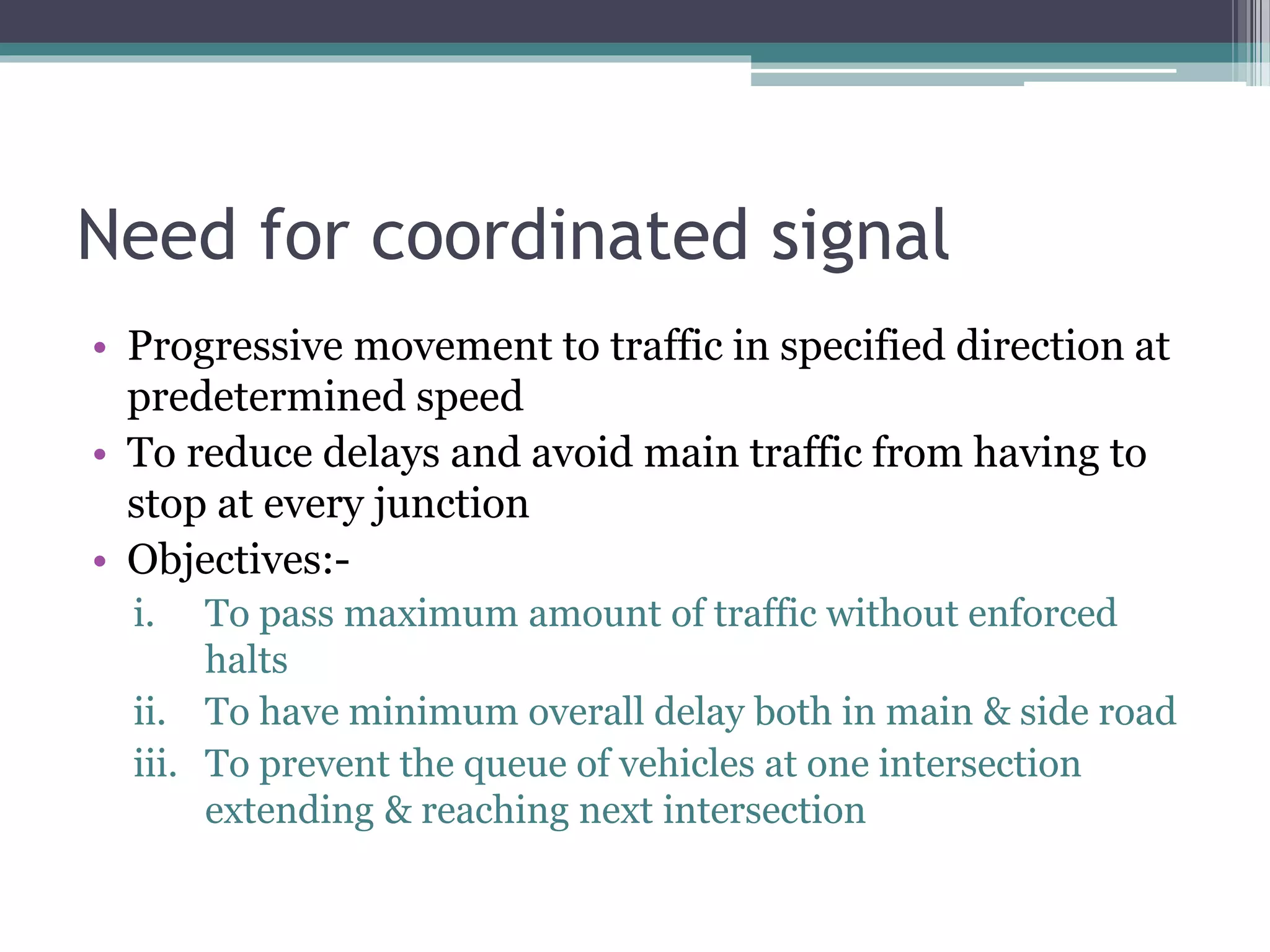
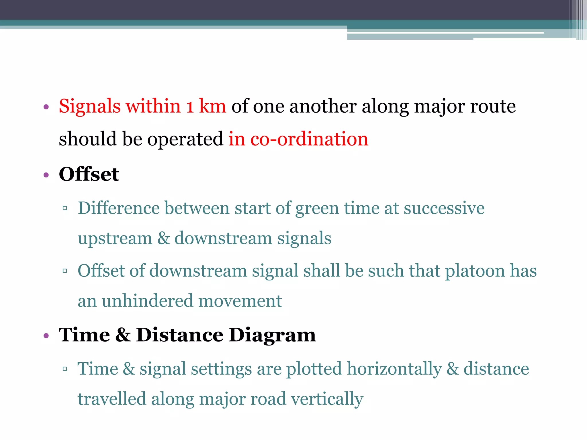
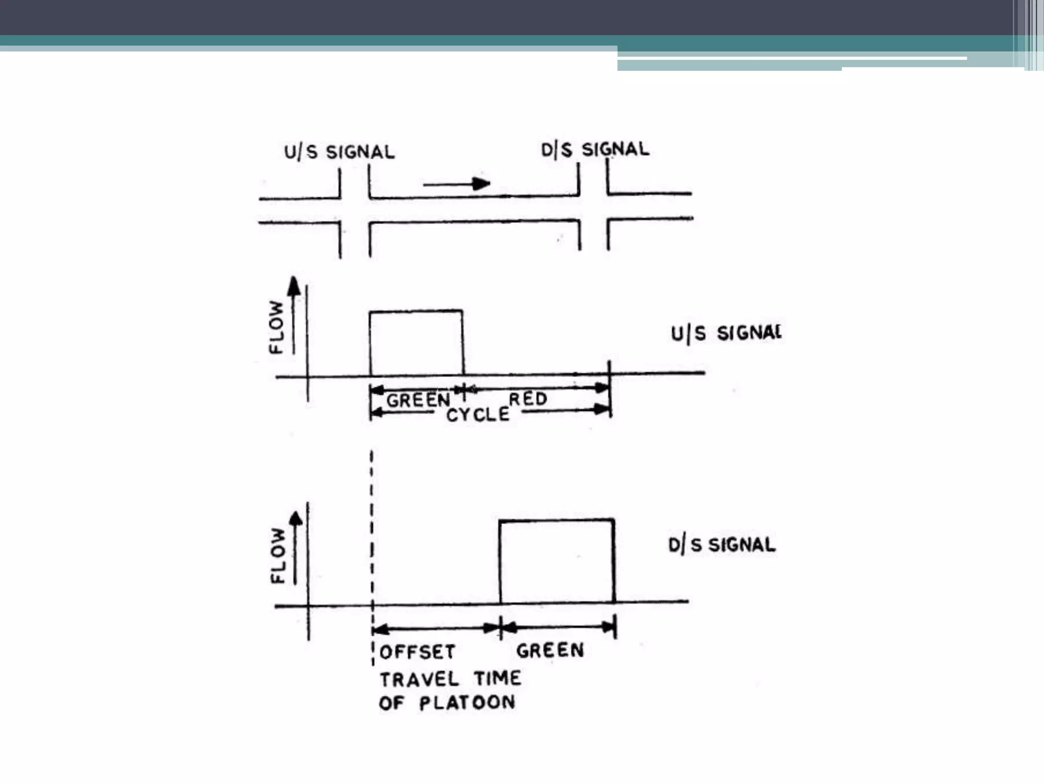
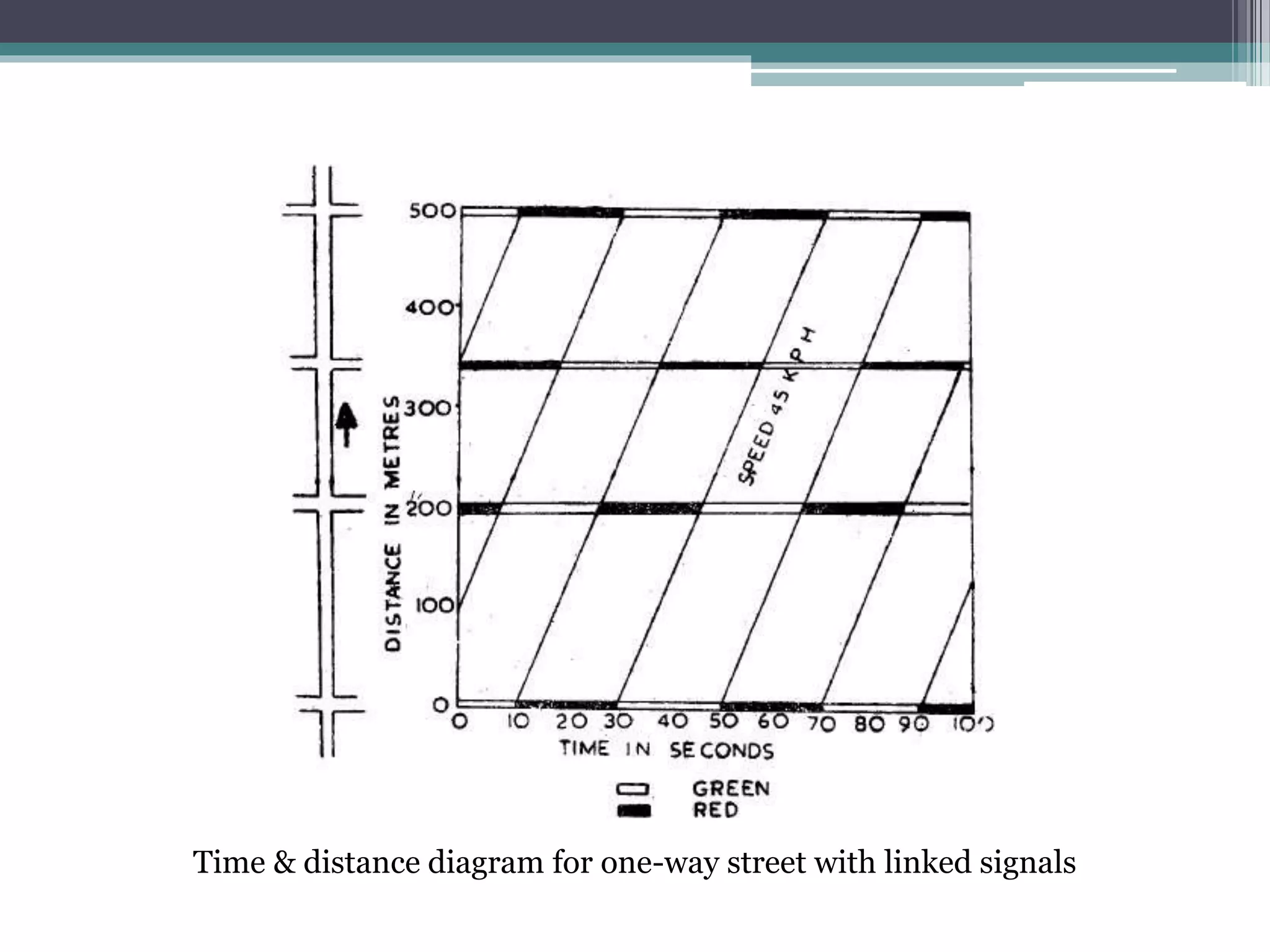
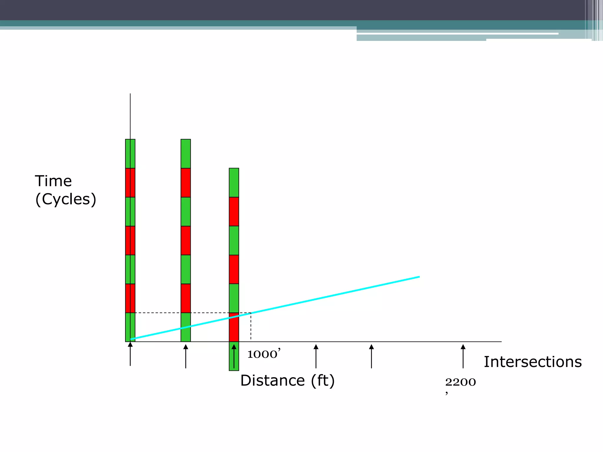
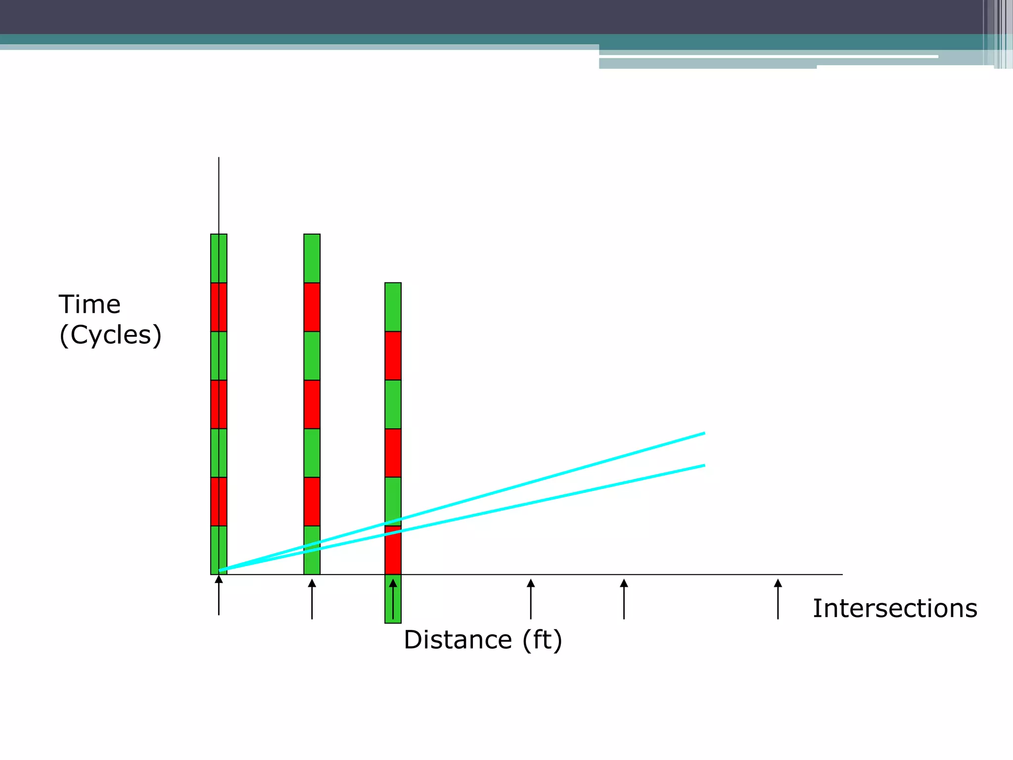
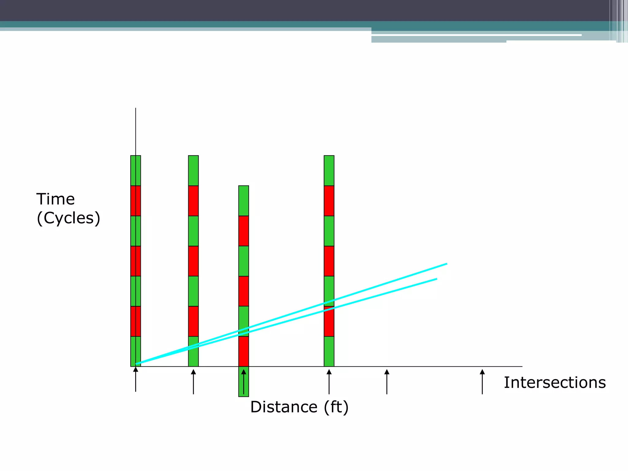
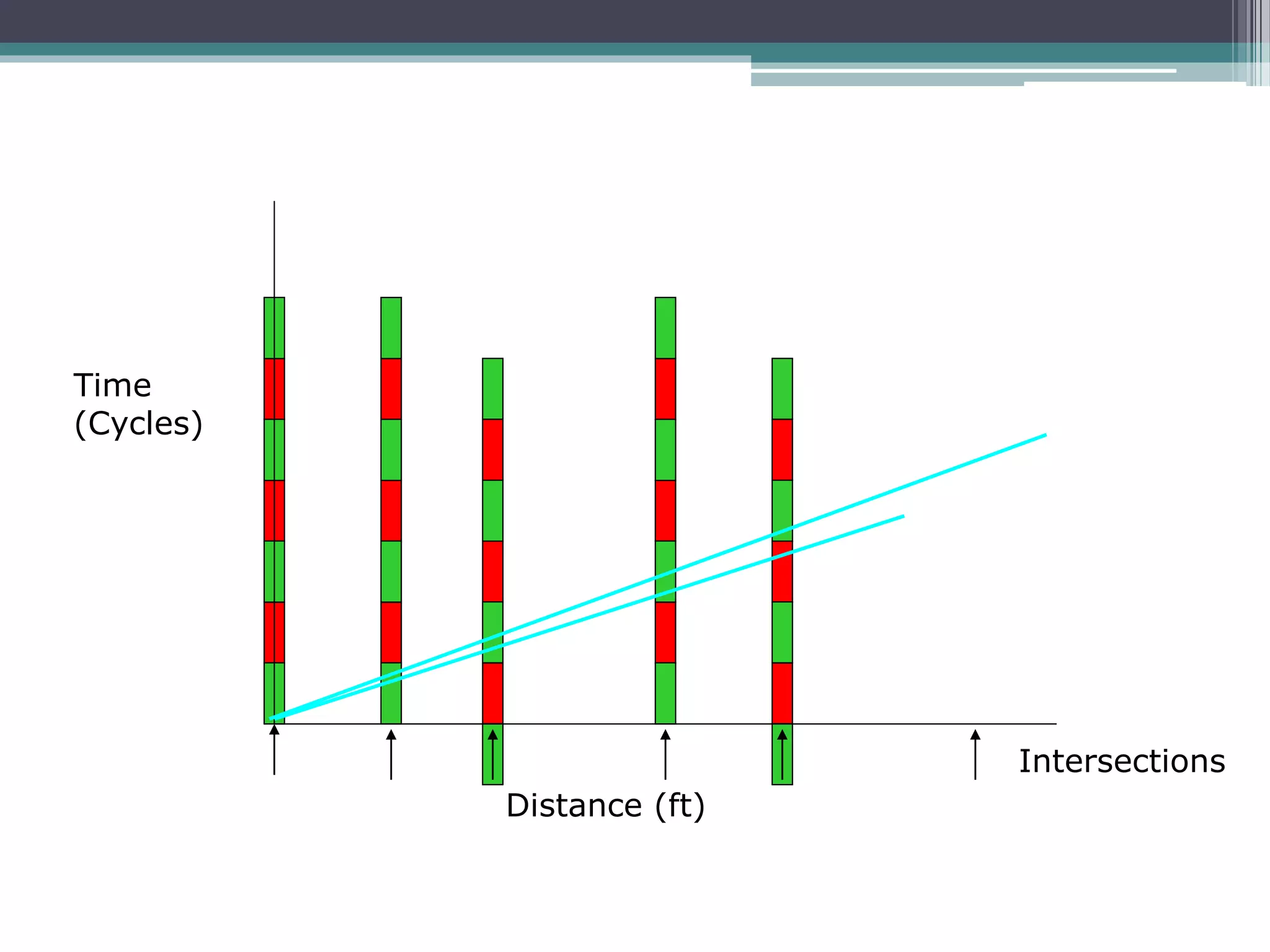
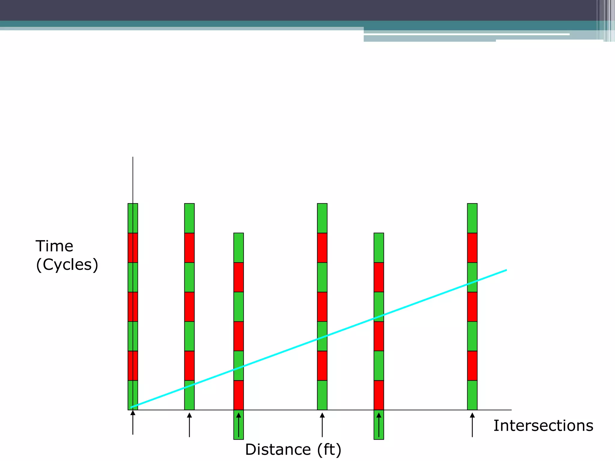
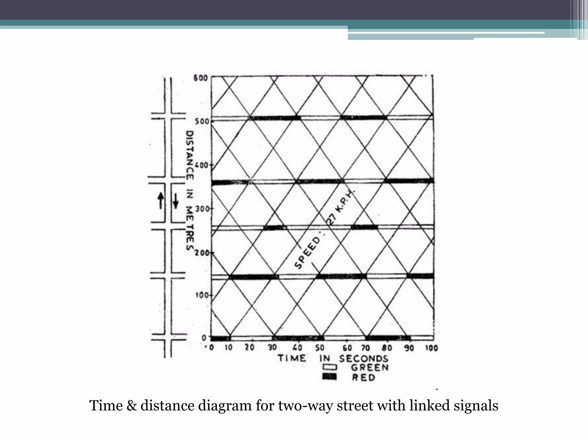
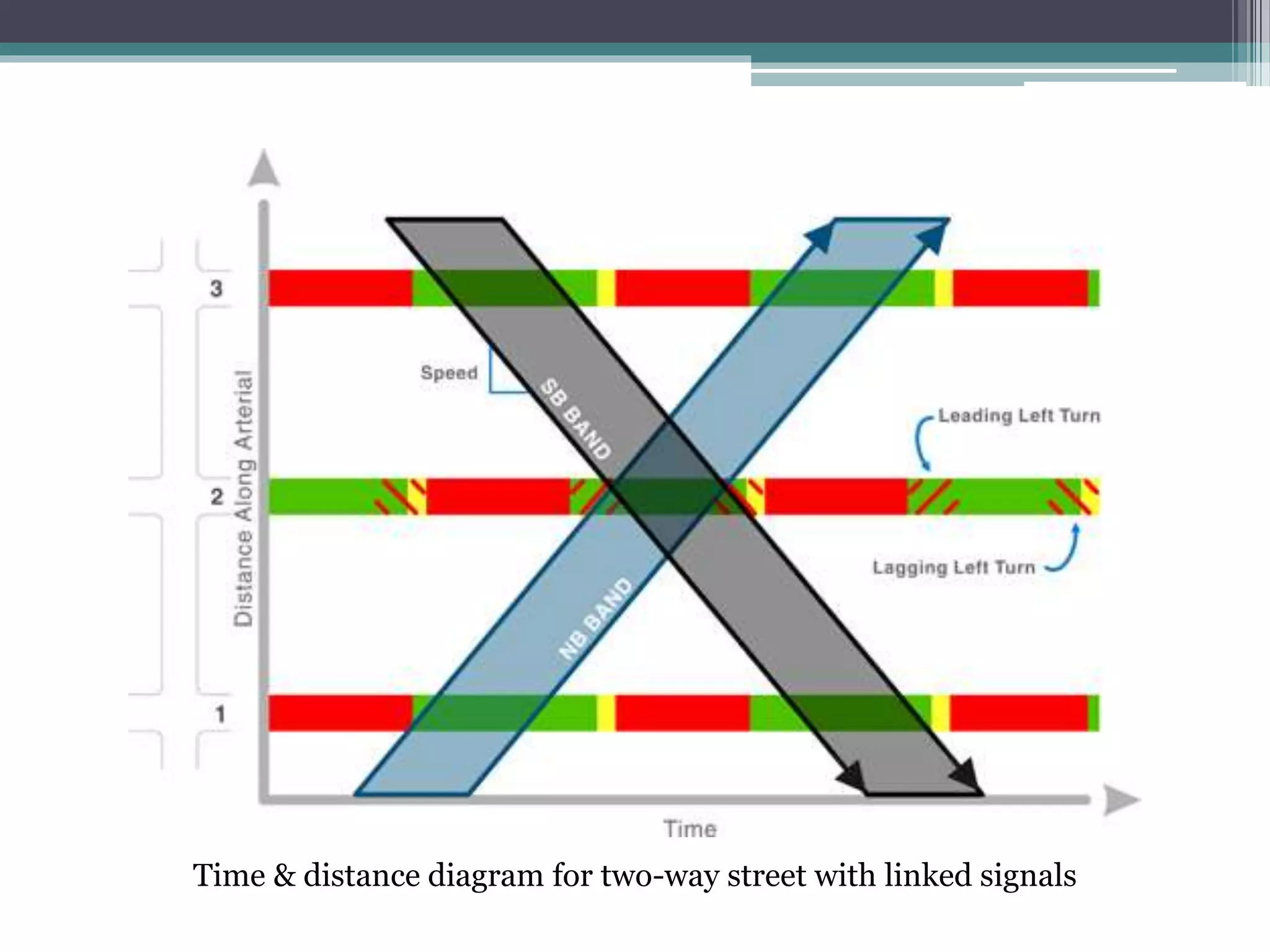
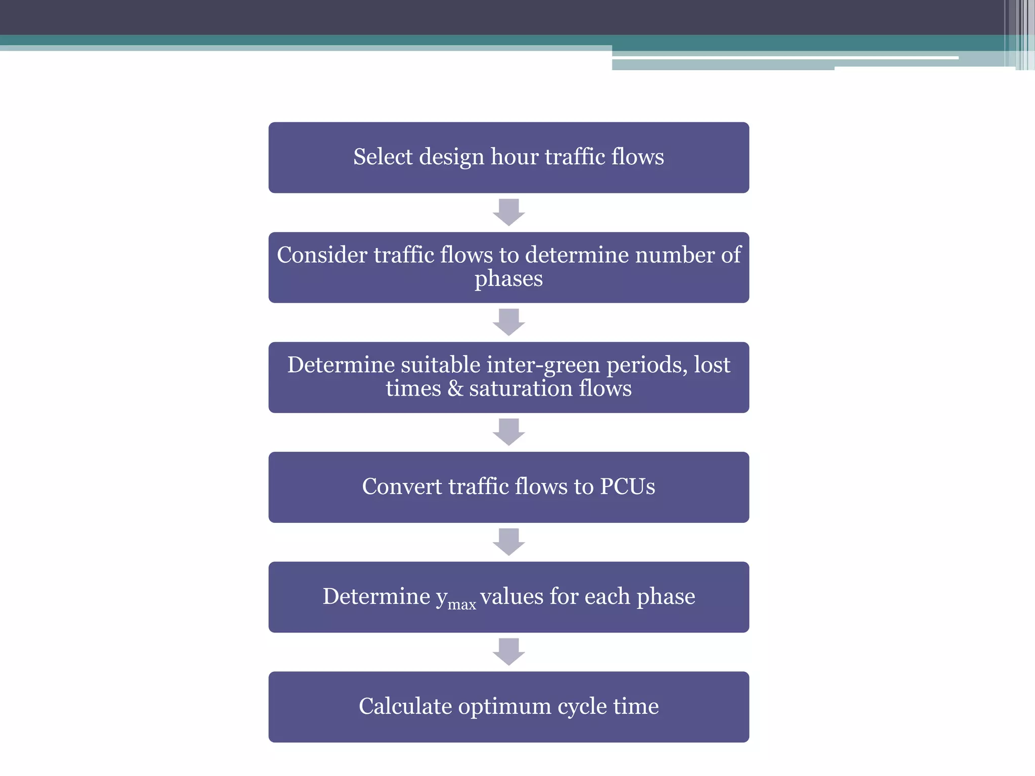
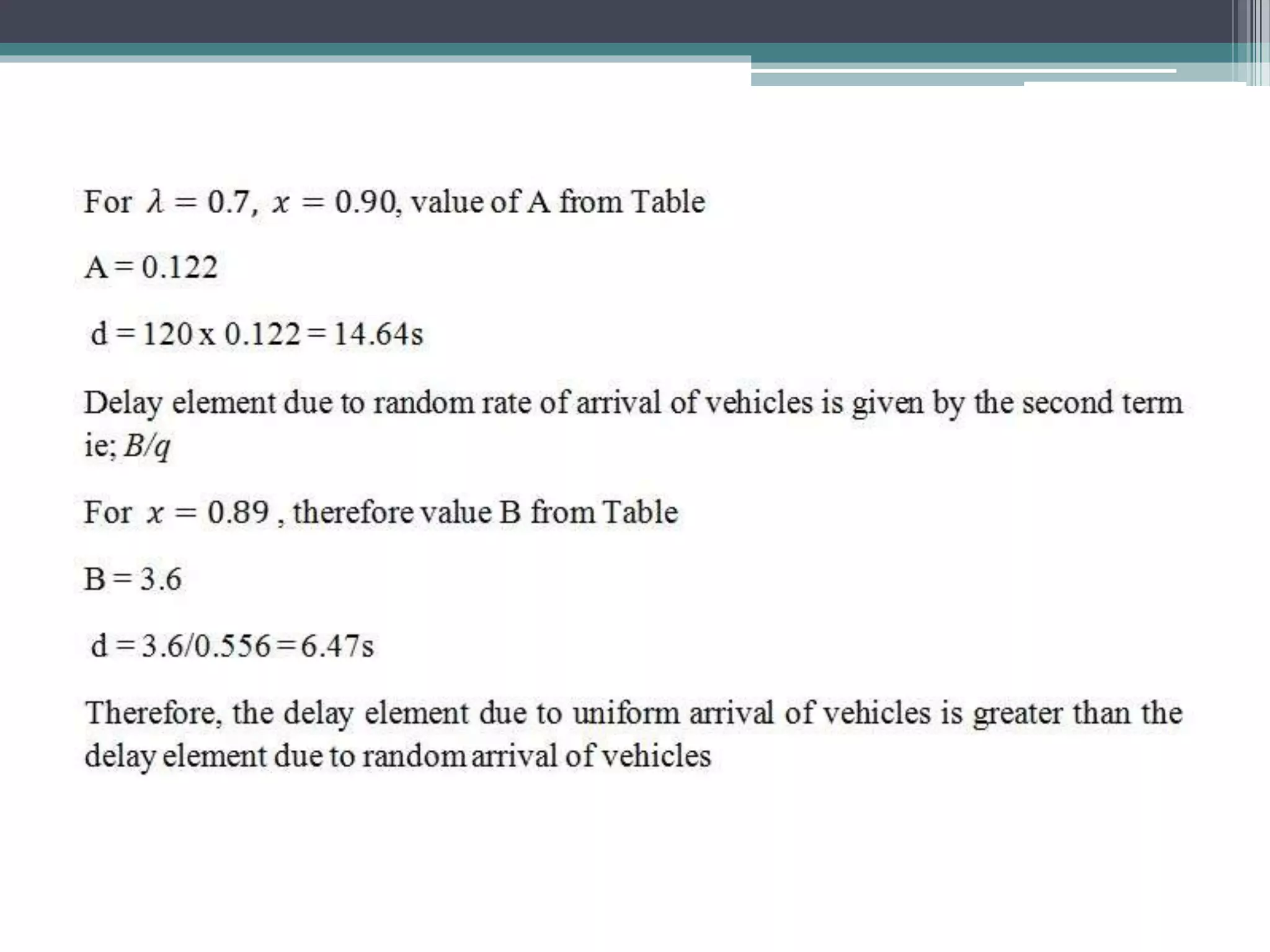
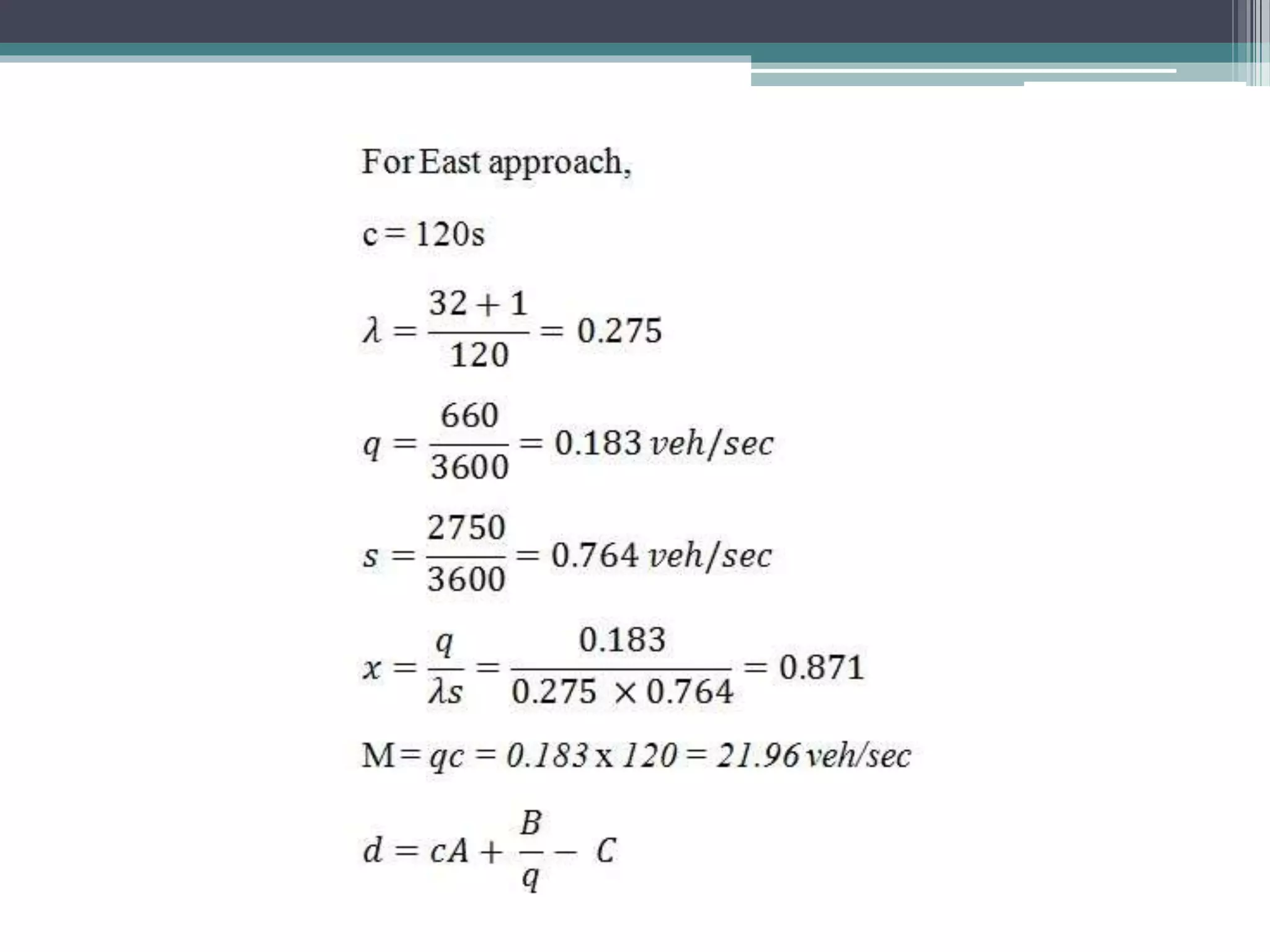
This document provides guidelines for traffic signal design and operation. It discusses: 1. Signal types including fixed time, vehicle actuated, and semi-vehicle actuated signals. Signal displays include green, amber, and red indications. 2. Warrants for signal installation based on minimum vehicular or pedestrian volumes, interruption of traffic flow, or accident experience. 3. Design considerations like signal height, location, size of lenses, and maintenance procedures. Traffic data collection and site conditions should also be analyzed. 4. Coordinated signal timing using time-distance diagrams to allow continuous traffic flow at a predetermined speed along a route with multiple signals.


![ANPARA THERMAL POWER STATION[1] sangam.pdf](https://cdn.slidesharecdn.com/ss_thumbnails/anparathermalpowerstation1sangam-251121115219-9261cde4-thumbnail.jpg?width=640&height=640&fit=bounds)


