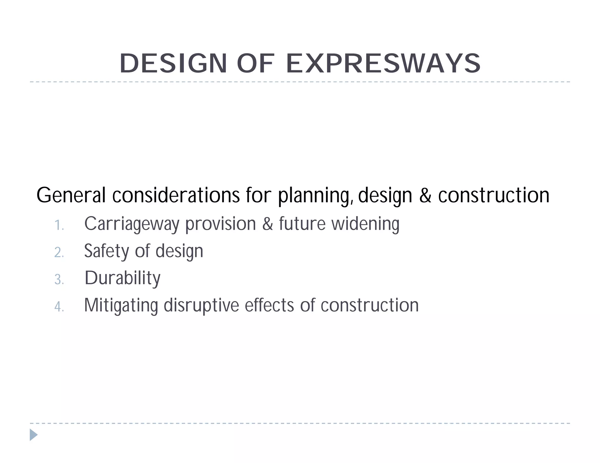
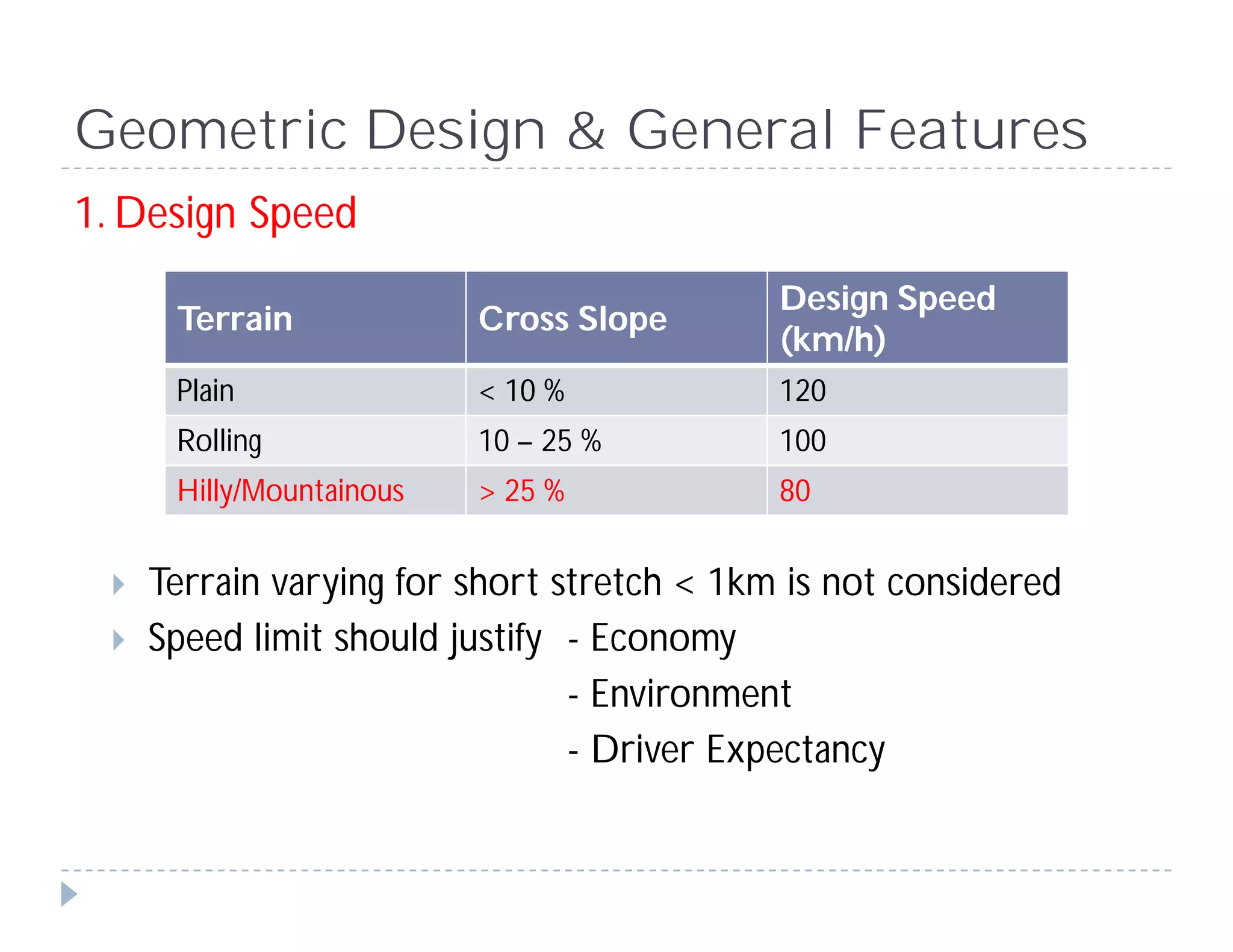
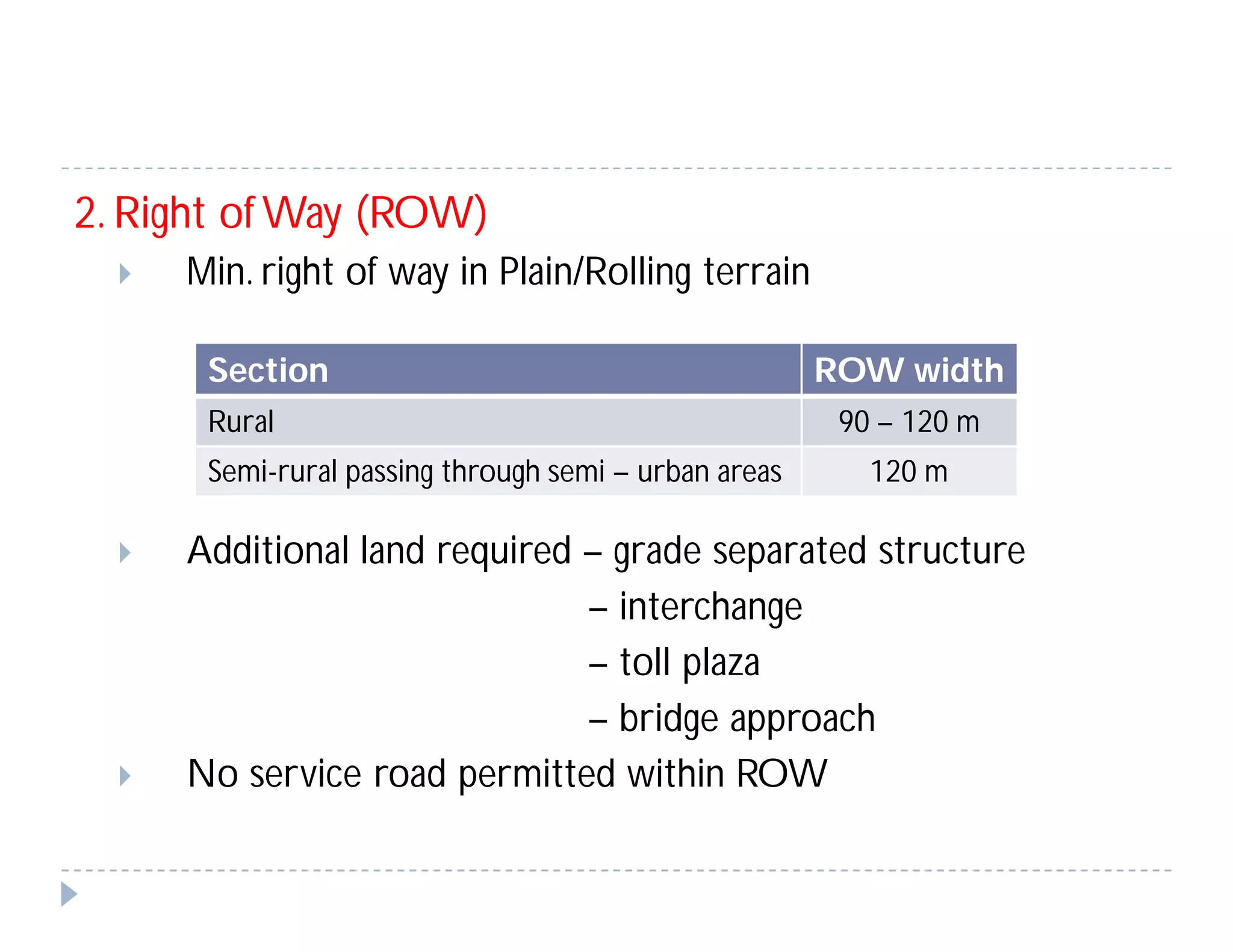
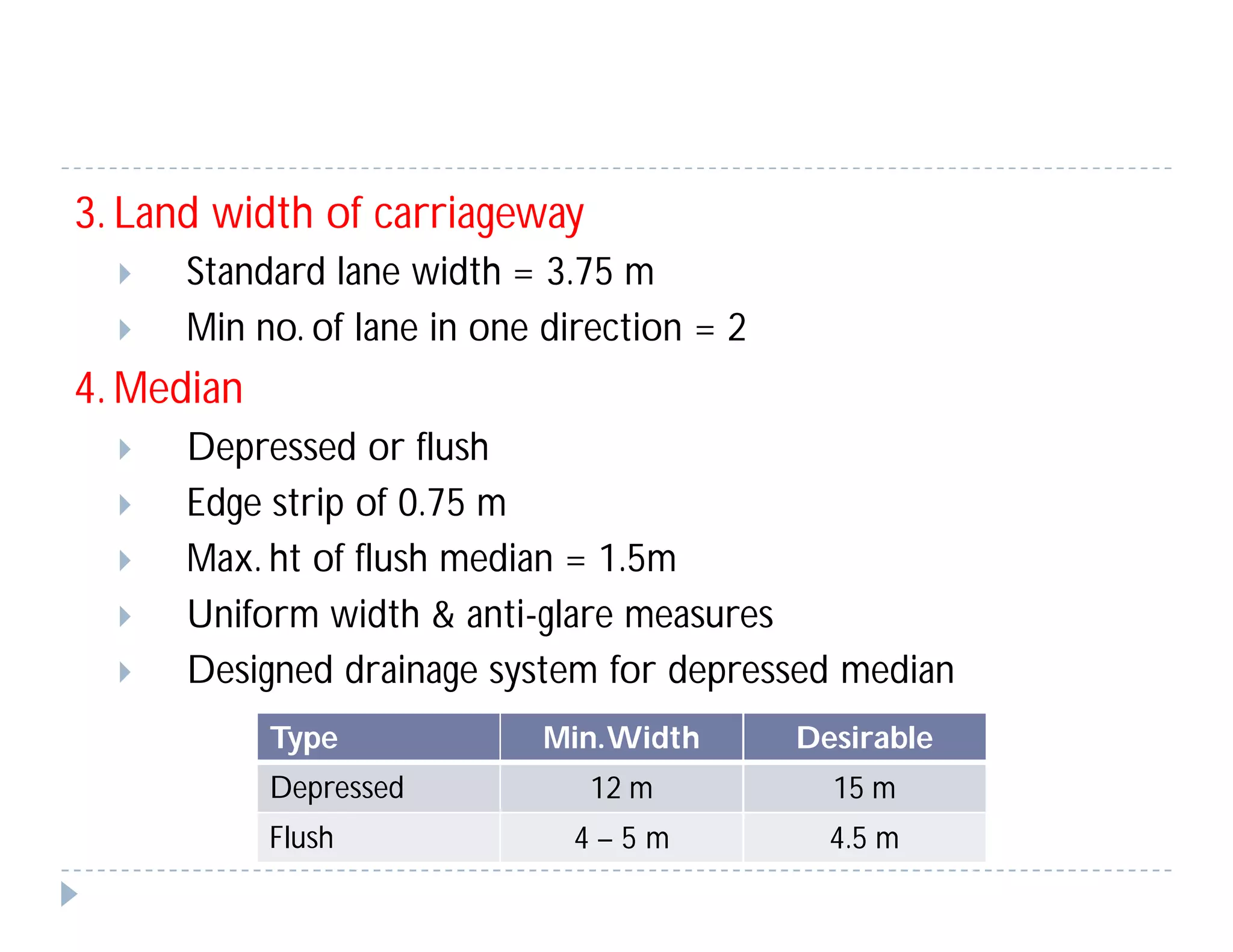
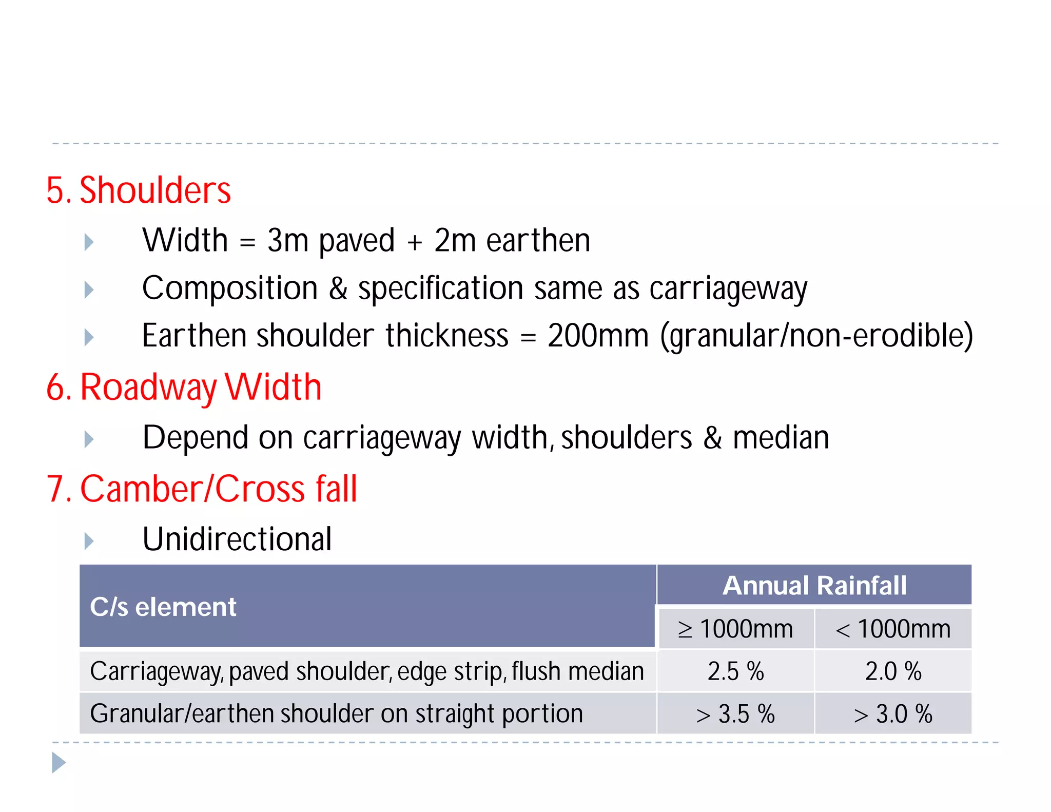
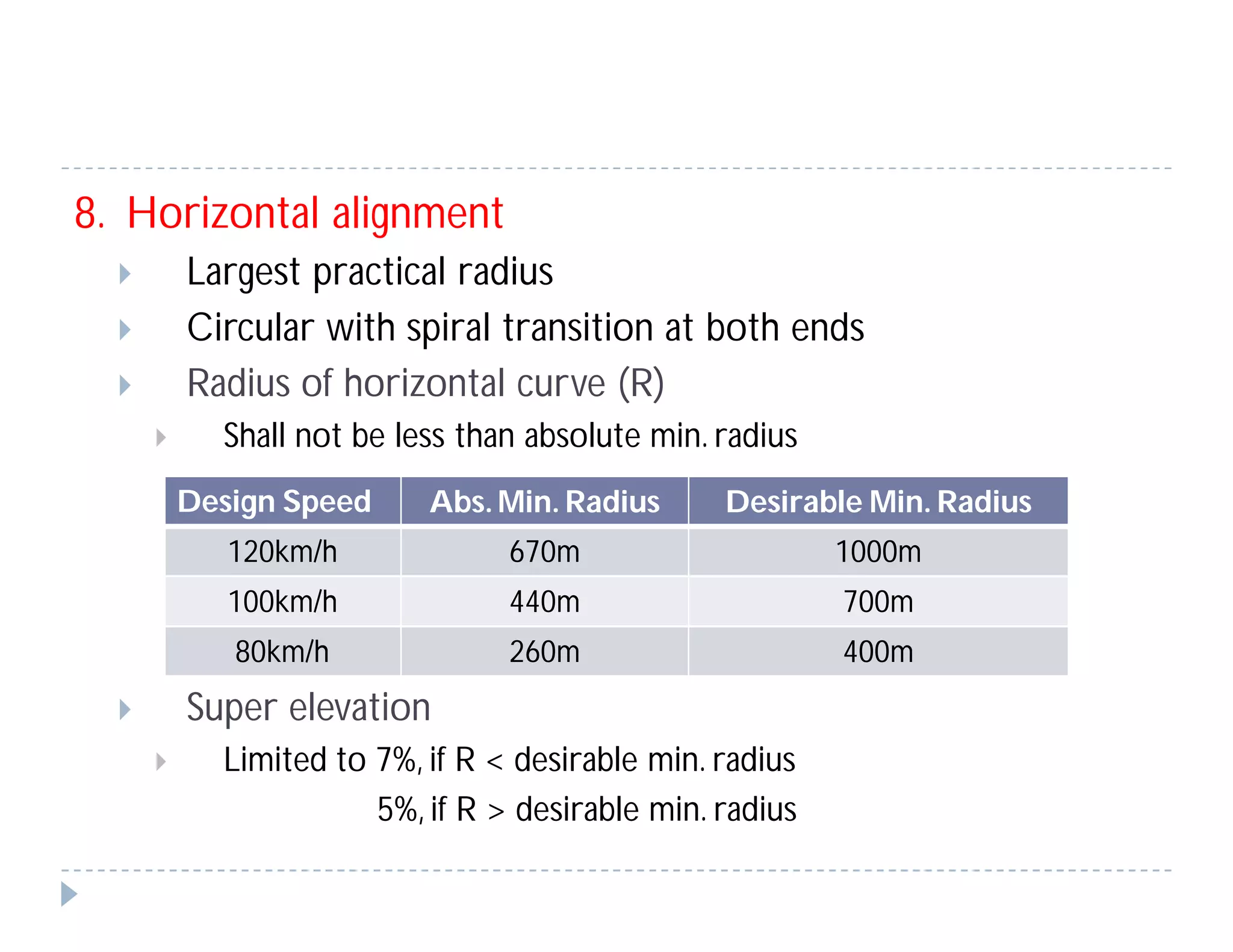
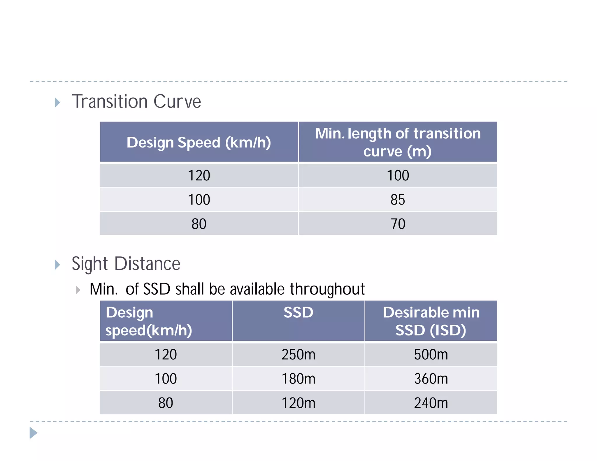
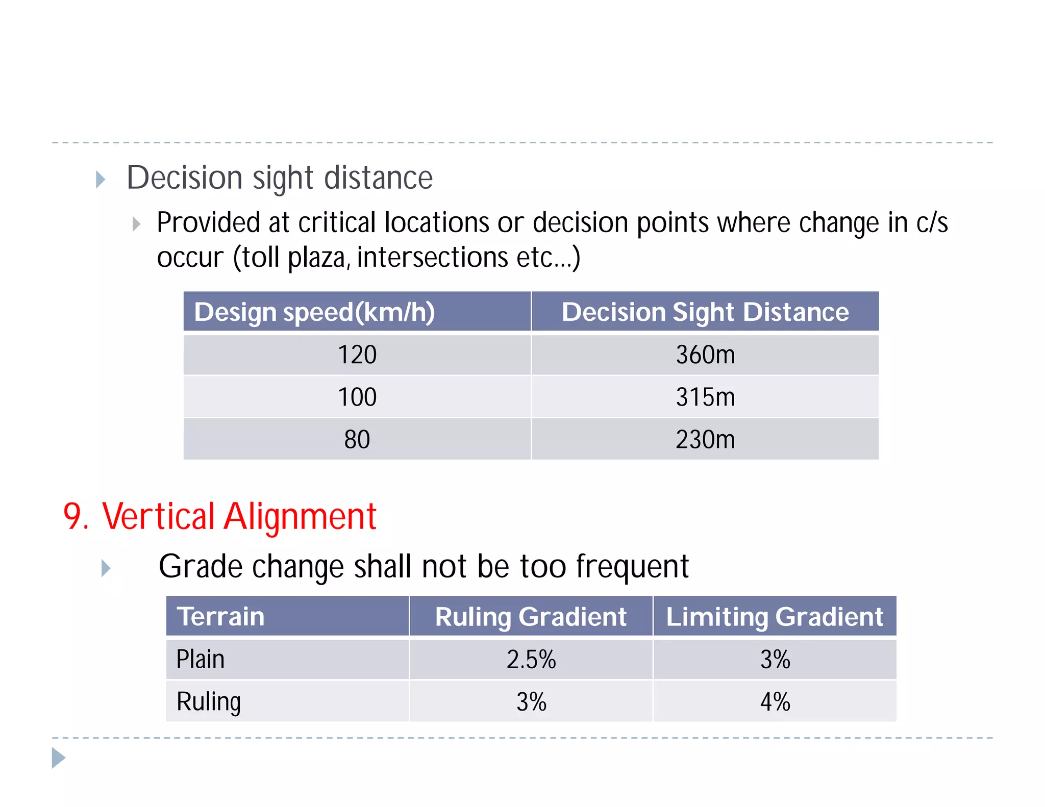
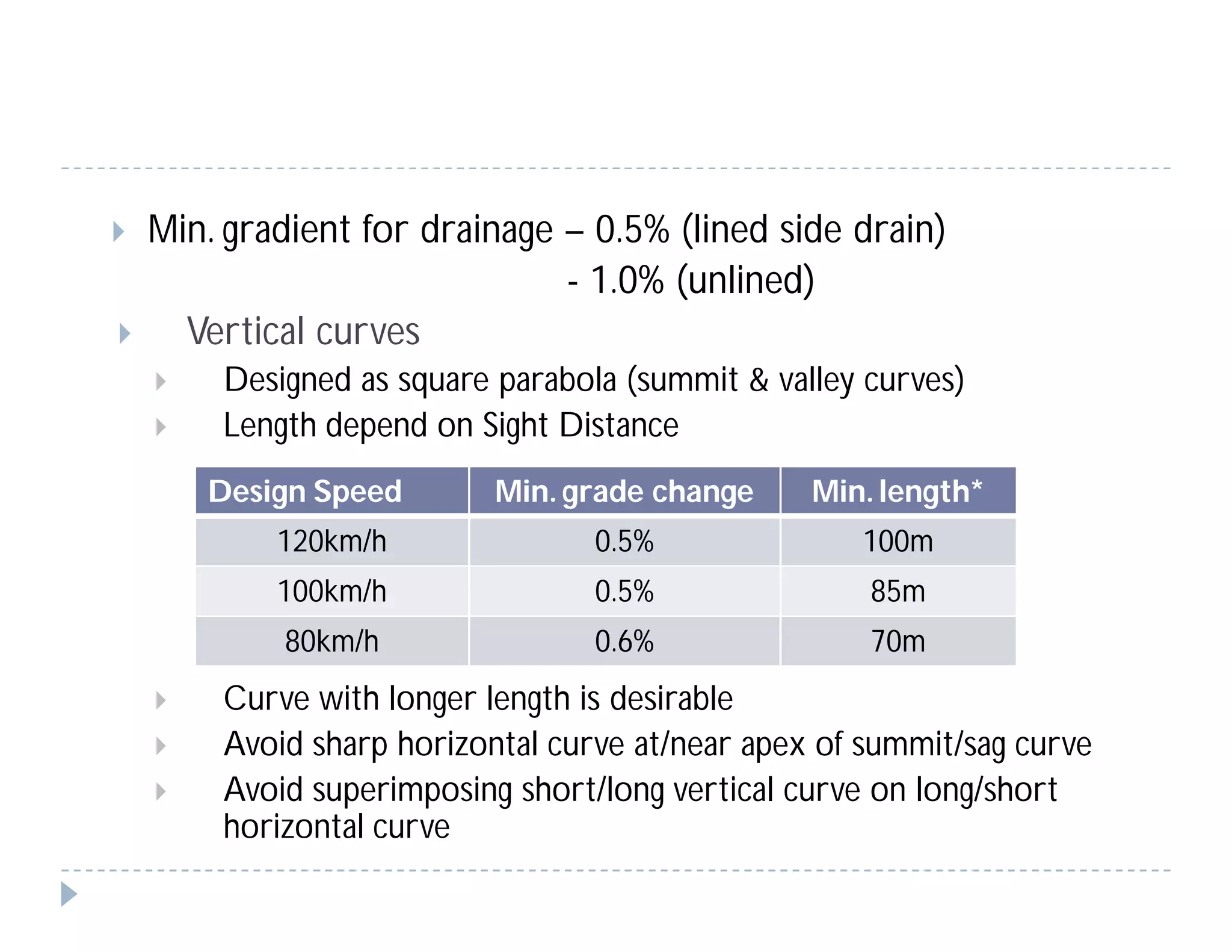
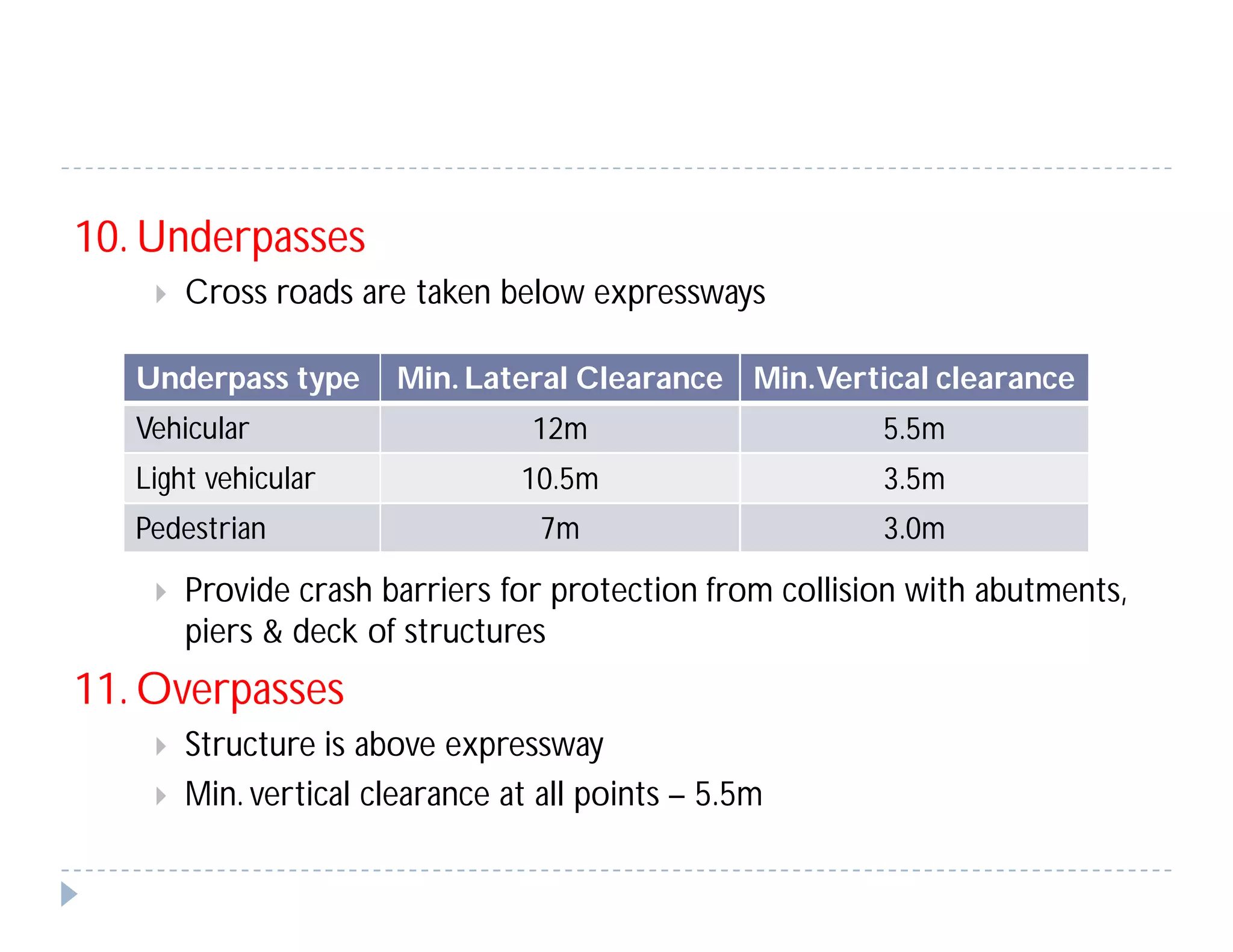
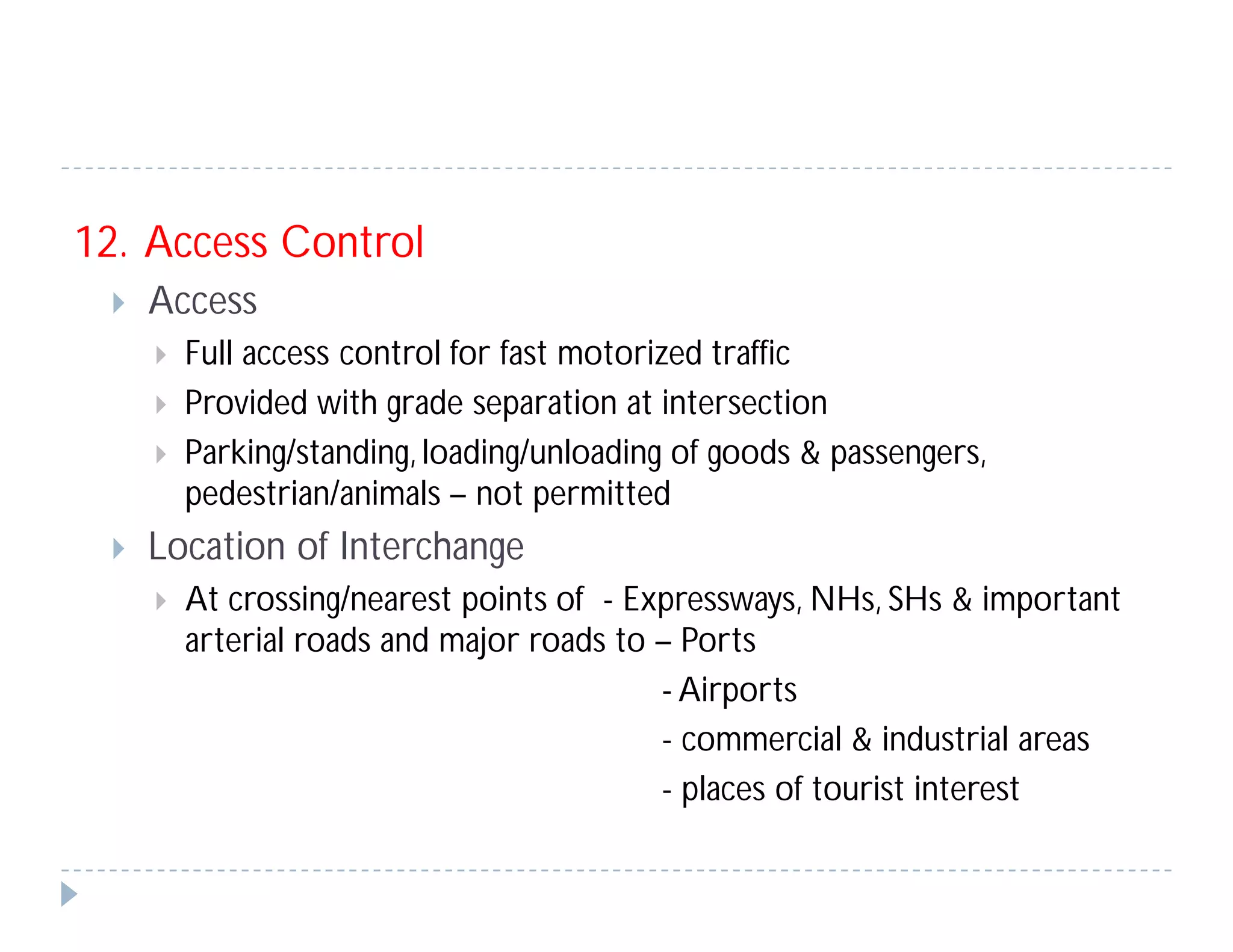
VIJAI KRISHNANV.
M.Tech Student
Transportation Engineering
Rajiv Gandhi Institute ofTechnology, Kottayam, Kerala
DESIGN OF EXPRESWAYS
General considerations for planning, design & construction
1. Carriageway provision & future widening
2. Safety of design
3. Durability
4. Mitigating disruptive effects of construction
Geometric Design & General Features
1. Design Speed
 Terrain varying for short stretch < 1km is not considered
 Speed limit should justify - Economy
- Environment
- Driver Expectancy
Terrain Cross Slope
Design Speed
(km/h)
Plain < 10 % 120
Rolling 10 – 25 % 100
Hilly/Mountainous > 25 % 80
2. Right of Way (ROW)
 Min. right of way in Plain/Rolling terrain
 Additional land required – grade separated structure
– interchange
– toll plaza
– bridge approach
 No service road permitted within ROW
Section ROW width
Rural 90 – 120 m
Semi-rural passing through semi – urban areas 120 m
3. Land width of carriageway
 Standard lane width = 3.75 m
 Min no. of lane in one direction = 2
4. Median
 Depressed or flush
 Edge strip of 0.75 m
 Max. ht of flush median = 1.5m
 Uniform width & anti-glare measures
 Designed drainage system for depressed median
Type Min.Width Desirable
Depressed 12 m 15 m
Flush 4 – 5 m 4.5 m
5. Shoulders
 Width = 3m paved + 2m earthen
 Composition & specification same as carriageway
 Earthen shoulder thickness = 200mm (granular/non-erodible)
6. Roadway Width
 Depend on carriageway width, shoulders & median
7. Camber/Cross fall
 Unidirectional
C/s element
Annual Rainfall
 1000mm  1000mm
Carriageway,paved shoulder,edge strip, flush median 2.5 % 2.0 %
Granular/earthen shoulder on straight portion  3.5 %  3.0 %
8. Horizontal alignment
 Largest practical radius
 Circular with spiral transition at both ends
 Radius of horizontal curve (R)
 Shall not be less than absolute min. radius
 Super elevation
 Limited to 7%, if R < desirable min. radius
5%, if R > desirable min. radius
Design Speed Abs. Min. Radius Desirable Min. Radius
120km/h 670m 1000m
100km/h 440m 700m
80km/h 260m 400m
 Transition Curve
 Sight Distance
 Min. of SSD shall be available throughout
Design Speed (km/h)
Min. length of transition
curve (m)
120 100
100 85
80 70
Design
speed(km/h)
SSD Desirable min
SSD (ISD)
120 250m 500m
100 180m 360m
80 120m 240m
 Decision sight distance
 Provided at critical locations or decision points where change in c/s
occur (toll plaza, intersections etc...)
9. Vertical Alignment
 Grade change shall not be too frequent
Design speed(km/h) Decision Sight Distance
120 360m
100 315m
80 230m
Terrain Ruling Gradient Limiting Gradient
Plain 2.5% 3%
Ruling 3% 4%
 Min. gradient for drainage – 0.5% (lined side drain)
- 1.0% (unlined)
 Vertical curves
 Designed as square parabola (summit & valley curves)
 Length depend on Sight Distance
 Curve with longer length is desirable
 Avoid sharp horizontal curve at/near apex of summit/sag curve
 Avoid superimposing short/long vertical curve on long/short
horizontal curve
Design Speed Min. grade change Min. length*
120km/h 0.5% 100m
100km/h 0.5% 85m
80km/h 0.6% 70m
10. Underpasses
 Cross roads are taken below expressways
 Provide crash barriers for protection from collision with abutments,
piers & deck of structures
11. Overpasses
 Structure is above expressway
 Min. vertical clearance at all points – 5.5m
Underpass type Min. Lateral Clearance Min.Vertical clearance
Vehicular 12m 5.5m
Light vehicular 10.5m 3.5m
Pedestrian 7m 3.0m
12. Access Control
 Access
 Full access control for fast motorized traffic
 Provided with grade separation at intersection
 Parking/standing, loading/unloading of goods & passengers,
pedestrian/animals – not permitted
 Location of Interchange
 At crossing/nearest points of - Expressways, NHs, SHs & important
arterial roads and major roads to – Ports
- Airports
- commercial & industrial areas
- places of tourist interest
 Connecting Roads
 For proper circulation of local traffic
 Continuity of travel
 To facilitate crossing over to other side of expressways through under
or overpass
 Fencing is provided
 Width = 7m
13. Grade separated structures
 Approach gradient < 2.5%
 Intersection where parallel cross roads are located within 2km,
design as staggered crossing
 In built-up areas, expressway is elevated on viaduct
 Decision to construct a grade separated structure is taken
based on - Drainage
- Land acquisition
- Height of embankment
- Provision of ramp
- Project economy
 Structure is decided to be underpass/overpass based on:-
- Nature of terrain
-Vertical profile of road
- availability of adequate sight distance
 Pedestrian Underpass/overpass
 Max. distance to reach crossing facility = 500m
 Provided within 2 km of vehicular under/overpass & 200m from
school/hospital/factory/industrial area
 Provision for disabled persons
14. Median Opening
 Provided at 5km spacing with detachable barrier
 Should not be located on curves & closer than 450m from any
structure/speed change taper
15. Fencing & Boundary Stones
 Fencing - at 2m inside of ROW boundary
- Height = 2.5m
- Made of mild steel & welded steel wire mesh
- Fencing post is embedded in M15 concrete
- Anti-corrosive paint on exposed metal surface
 Boundary stones - to demarcate ROW
- spacing = 100m
- made of cement concrete
- painted with cement primer & enamel paint
Design of expressways

Design of expressways

  • 1.
    VIJAI KRISHNANV. M.Tech Student TransportationEngineering Rajiv Gandhi Institute ofTechnology, Kottayam, Kerala
  • 2.
    DESIGN OF EXPRESWAYS Generalconsiderations for planning, design & construction 1. Carriageway provision & future widening 2. Safety of design 3. Durability 4. Mitigating disruptive effects of construction
  • 3.
    Geometric Design &General Features 1. Design Speed  Terrain varying for short stretch < 1km is not considered  Speed limit should justify - Economy - Environment - Driver Expectancy Terrain Cross Slope Design Speed (km/h) Plain < 10 % 120 Rolling 10 – 25 % 100 Hilly/Mountainous > 25 % 80
  • 4.
    2. Right ofWay (ROW)  Min. right of way in Plain/Rolling terrain  Additional land required – grade separated structure – interchange – toll plaza – bridge approach  No service road permitted within ROW Section ROW width Rural 90 – 120 m Semi-rural passing through semi – urban areas 120 m
  • 5.
    3. Land widthof carriageway  Standard lane width = 3.75 m  Min no. of lane in one direction = 2 4. Median  Depressed or flush  Edge strip of 0.75 m  Max. ht of flush median = 1.5m  Uniform width & anti-glare measures  Designed drainage system for depressed median Type Min.Width Desirable Depressed 12 m 15 m Flush 4 – 5 m 4.5 m
  • 6.
    5. Shoulders  Width= 3m paved + 2m earthen  Composition & specification same as carriageway  Earthen shoulder thickness = 200mm (granular/non-erodible) 6. Roadway Width  Depend on carriageway width, shoulders & median 7. Camber/Cross fall  Unidirectional C/s element Annual Rainfall  1000mm  1000mm Carriageway,paved shoulder,edge strip, flush median 2.5 % 2.0 % Granular/earthen shoulder on straight portion  3.5 %  3.0 %
  • 7.
    8. Horizontal alignment Largest practical radius  Circular with spiral transition at both ends  Radius of horizontal curve (R)  Shall not be less than absolute min. radius  Super elevation  Limited to 7%, if R < desirable min. radius 5%, if R > desirable min. radius Design Speed Abs. Min. Radius Desirable Min. Radius 120km/h 670m 1000m 100km/h 440m 700m 80km/h 260m 400m
  • 8.
     Transition Curve Sight Distance  Min. of SSD shall be available throughout Design Speed (km/h) Min. length of transition curve (m) 120 100 100 85 80 70 Design speed(km/h) SSD Desirable min SSD (ISD) 120 250m 500m 100 180m 360m 80 120m 240m
  • 9.
     Decision sightdistance  Provided at critical locations or decision points where change in c/s occur (toll plaza, intersections etc...) 9. Vertical Alignment  Grade change shall not be too frequent Design speed(km/h) Decision Sight Distance 120 360m 100 315m 80 230m Terrain Ruling Gradient Limiting Gradient Plain 2.5% 3% Ruling 3% 4%
  • 10.
     Min. gradientfor drainage – 0.5% (lined side drain) - 1.0% (unlined)  Vertical curves  Designed as square parabola (summit & valley curves)  Length depend on Sight Distance  Curve with longer length is desirable  Avoid sharp horizontal curve at/near apex of summit/sag curve  Avoid superimposing short/long vertical curve on long/short horizontal curve Design Speed Min. grade change Min. length* 120km/h 0.5% 100m 100km/h 0.5% 85m 80km/h 0.6% 70m
  • 11.
    10. Underpasses  Crossroads are taken below expressways  Provide crash barriers for protection from collision with abutments, piers & deck of structures 11. Overpasses  Structure is above expressway  Min. vertical clearance at all points – 5.5m Underpass type Min. Lateral Clearance Min.Vertical clearance Vehicular 12m 5.5m Light vehicular 10.5m 3.5m Pedestrian 7m 3.0m
  • 12.
    12. Access Control Access  Full access control for fast motorized traffic  Provided with grade separation at intersection  Parking/standing, loading/unloading of goods & passengers, pedestrian/animals – not permitted  Location of Interchange  At crossing/nearest points of - Expressways, NHs, SHs & important arterial roads and major roads to – Ports - Airports - commercial & industrial areas - places of tourist interest
  • 13.
     Connecting Roads For proper circulation of local traffic  Continuity of travel  To facilitate crossing over to other side of expressways through under or overpass  Fencing is provided  Width = 7m 13. Grade separated structures  Approach gradient < 2.5%  Intersection where parallel cross roads are located within 2km, design as staggered crossing  In built-up areas, expressway is elevated on viaduct
  • 14.
     Decision toconstruct a grade separated structure is taken based on - Drainage - Land acquisition - Height of embankment - Provision of ramp - Project economy  Structure is decided to be underpass/overpass based on:- - Nature of terrain -Vertical profile of road - availability of adequate sight distance
  • 15.
     Pedestrian Underpass/overpass Max. distance to reach crossing facility = 500m  Provided within 2 km of vehicular under/overpass & 200m from school/hospital/factory/industrial area  Provision for disabled persons 14. Median Opening  Provided at 5km spacing with detachable barrier  Should not be located on curves & closer than 450m from any structure/speed change taper
  • 16.
    15. Fencing &Boundary Stones  Fencing - at 2m inside of ROW boundary - Height = 2.5m - Made of mild steel & welded steel wire mesh - Fencing post is embedded in M15 concrete - Anti-corrosive paint on exposed metal surface  Boundary stones - to demarcate ROW - spacing = 100m - made of cement concrete - painted with cement primer & enamel paint