Download to read offline

![Specific Speed
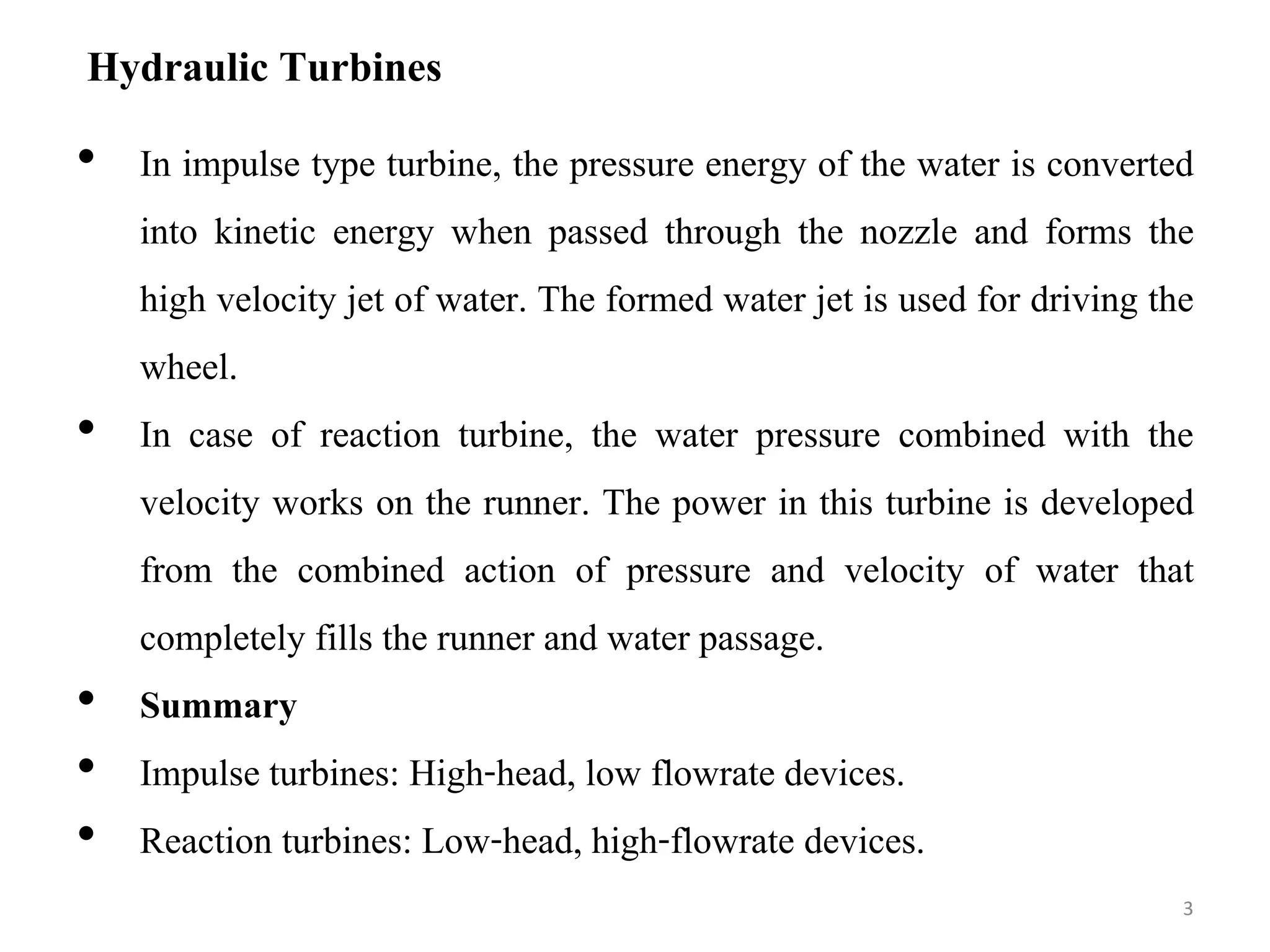
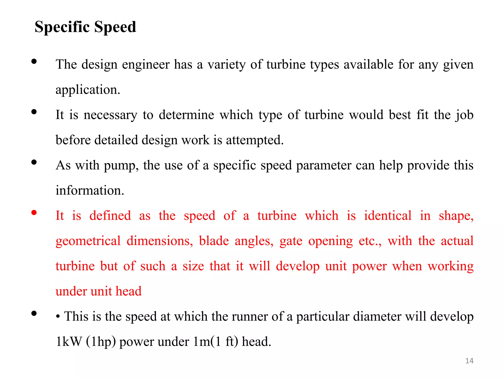
• It is defined as the speed of a turbine which is identical in shape,
geometrical dimensions, blade angles, gate opening etc., with the
actual turbine but of such a size that it will develop unit power when
working under unit head
• • This is the speed at which the runner of a particular diameter will
develop 1kW (1hp) power under 1m(1 ft) head.
15
4
/
5
)]
(
[
)
(
)
(
)
(
m
H
kW
P
rpm
N
rpm
Ns ](https://image.slidesharecdn.com/hydel-lecture-2-220312134029/75/Hydel-lecture-2-15-2048.jpg)
![Specific Speed
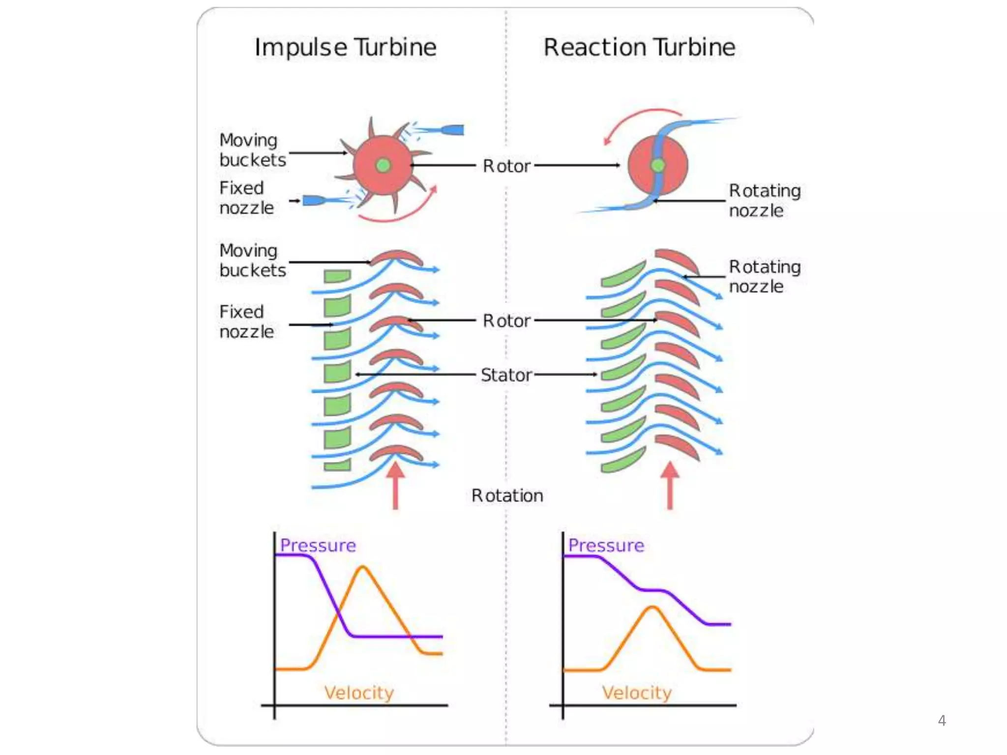
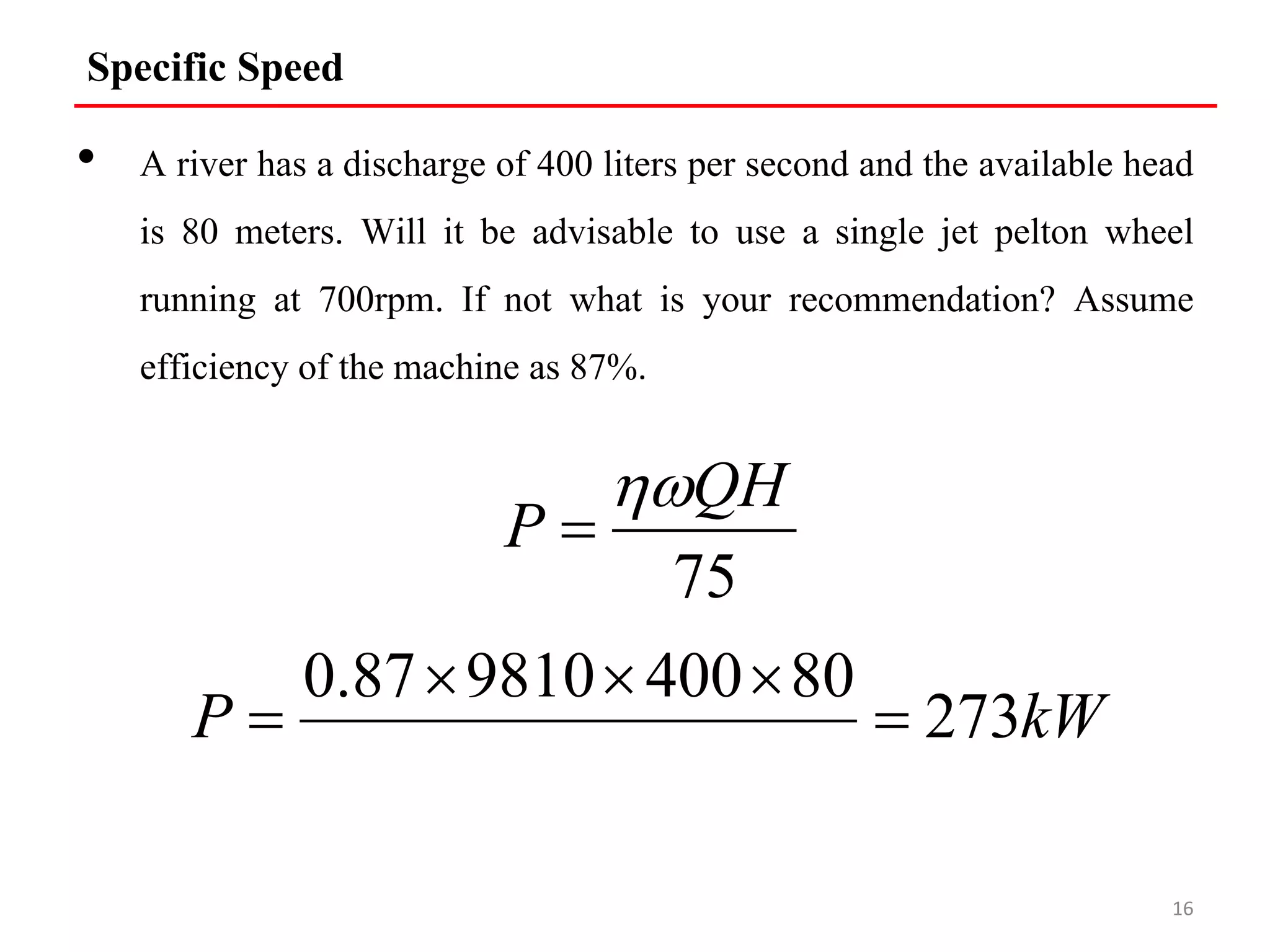
• The specific speed of the machine is given by
17
4
/
5
)]
(
[
)
(
)
(
)
(
m
H
kW
P
rpm
N
rpm
Ns
34
.
48
)]
(
80
[
273
)
(
700
)
( 4
/
5
m
rpm
rpm
Ns](https://image.slidesharecdn.com/hydel-lecture-2-220312134029/75/Hydel-lecture-2-17-2048.jpg)


![Specific Speed
• It is defined as the speed of a turbine which is identical in shape,
geometrical dimensions, blade angles, gate opening etc., with the
actual turbine but of such a size that it will develop unit power when
working under unit head
• • This is the speed at which the runner of a particular diameter will
develop 1kW (1hp) power under 1m(1 ft) head.
15
4
/
5
)]
(
[
)
(
)
(
)
(
m
H
kW
P
rpm
N
rpm
Ns ](https://crownmelresort.com/image.slidesharecdn.com/hydel-lecture-2-220312134029/75/Hydel-lecture-2-15-2048.jpg)

![Specific Speed
• The specific speed of the machine is given by
17
4
/
5
)]
(
[
)
(
)
(
)
(
m
H
kW
P
rpm
N
rpm
Ns
34
.
48
)]
(
80
[
273
)
(
700
)
( 4
/
5
m
rpm
rpm
Ns](https://crownmelresort.com/image.slidesharecdn.com/hydel-lecture-2-220312134029/75/Hydel-lecture-2-17-2048.jpg)


This document discusses different types of hydraulic turbines used in hydroelectric power plants. It describes how impulse turbines like Pelton wheels use jet water to drive the turbine, while reaction turbines like Francis and Kaplan turbines use both pressure and velocity of water filling the runner casing. It provides details on Pelton, Francis, and Kaplan turbine designs and applications based on specific speed. For a case study river with 80m head and 400L/s flow, the document recommends using a Francis turbine instead of a single Pelton wheel, since the specific speed calculated is outside the typical Pelton wheel range.


