This document describes the impulse turbine known as the Pelton turbine. It consists of a wheel with buckets that is struck by one or more high-velocity jets of water. The jet is produced by a nozzle that converts the potential energy of water from a reservoir into kinetic energy. As the jet strikes the buckets, it transfers momentum which spins the wheel and powers the turbine's shaft. Key components include the runner, buckets, nozzle, and casing. The document provides details on dimensions, speed ratio, jet ratio, and the number of jets used.
This slide introduces the presenters of the topic on impulse turbines.
It defines a turbine's role in converting high-grade energy from fluid into mechanical work, emphasizing site characteristics for optimal turbine selection.
Explains how steam's pressure drop is converted into kinetic energy, creating driving force through changing motion direction.
An introduction to Pelton turbines, highlighting their usage and characteristics as impulse turbines.
Describes how Pelton turbines use a water jet for energy conversion under high head conditions.
Details how the jet impacts the runner's buckets to produce mechanical power and discusses the number of nozzles.
Focuses on the runner's structure composed of double cupped buckets that split water jets for balance.
Describes the nozzle's role in energy conversion and flow regulation, including materials used.
Discusses the casing's protective role, material choice, and supporting structures for operation.
Presents specific measurements for bucket dimensions to optimize performance and energy transfer.
Explains factors affecting bucket count for ideal jet usage to minimize frictional loss.
Details the relationship between nozzle velocity and discharge rates for effective turbine operation.
Defines speed ratio, linking the wheel's tangential speed to theoretical jet velocity.
Defines and explores jet ratio based on runner diameter and nozzle diameter relationships.
Discusses the limitations on the number of jets in Pelton turbines for efficient governing.
DEFINITION OF TURBINE
A Turbine is a Form of Engine Requires a suitable working fluid in
order to function- a source of High Grade Energy and a Sink for Low
Grade energy. When a Fluid Flows through the Turbine ,Part of Energy
Content is Continuously Extracted andConverted in to Useful mechanical
Work.
• A turbine converts energy in the form of falling water into rotating shaft
power. The selection of the best turbine for any particular hydro site
depends on the site characteristics, the dominant ones being the head and
flow available. Selection also depends on the desired running speed of the
generator or other device loading the turbine. Other considerations such
as whether the turbine is expected to produce power under part-flow
conditions, also play an important role in the selection. All turbines have a
power-speed characteristic. They will tend to run most efficiently at a
particular speed, head and flow combination.
3.
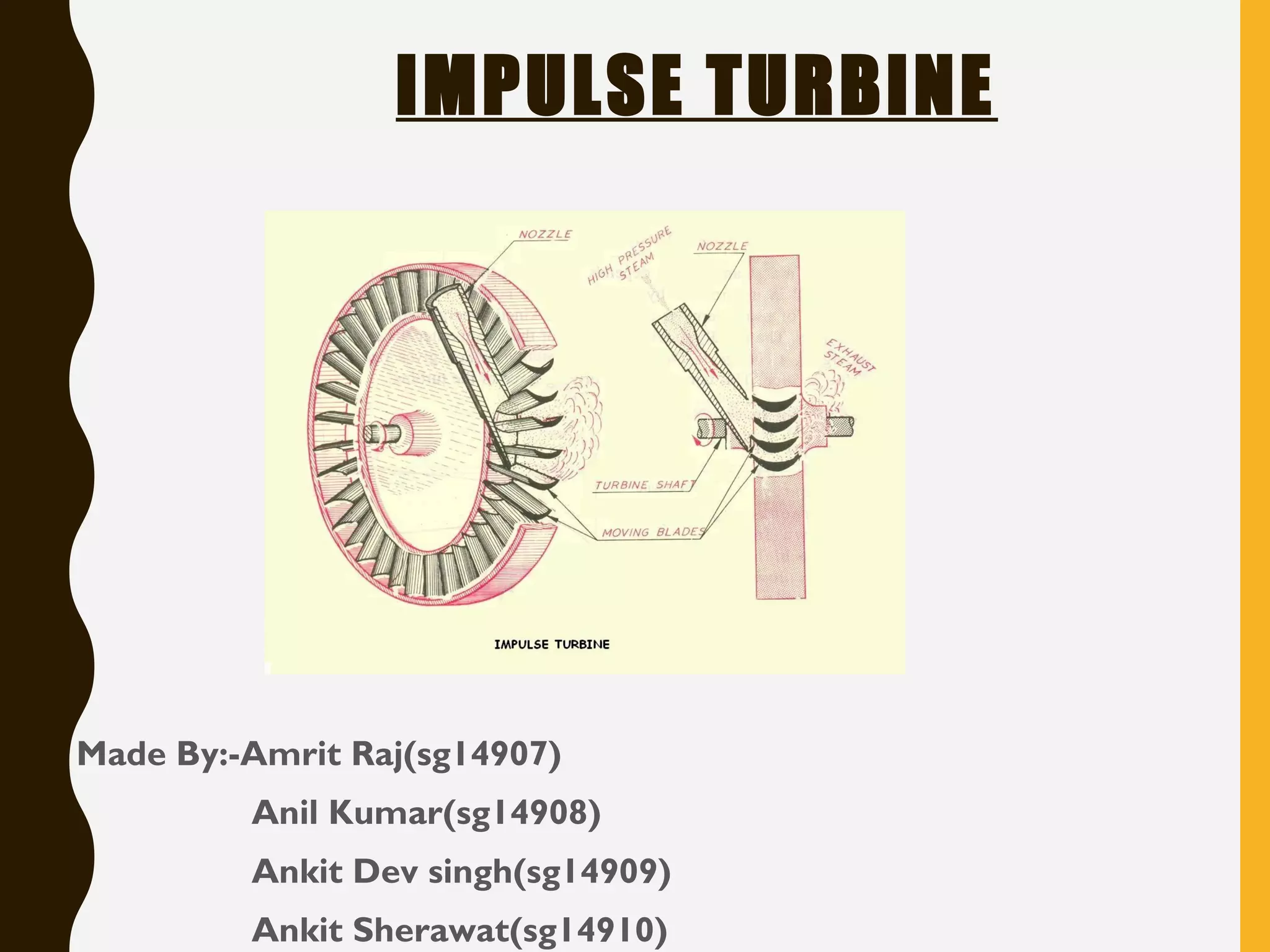
WORKING PRINCIPLE OF
IMPULSETURBINE
The steam is made to fall in its pressure by
expanding in a nozzle. Due to this fall in
pressure, a certain amount of heat energy is
converted into kinetic energy, which sets the
steam to flow with a greater velocity.
The rapidly moving particles of the steam enter the
rotating part of the turbine, where it undergoes a
change in the direction of motion, which gives rise to a change of
momentum and therefore force. This constitutes the driving
force of the turbine.
PELTON TURBINES
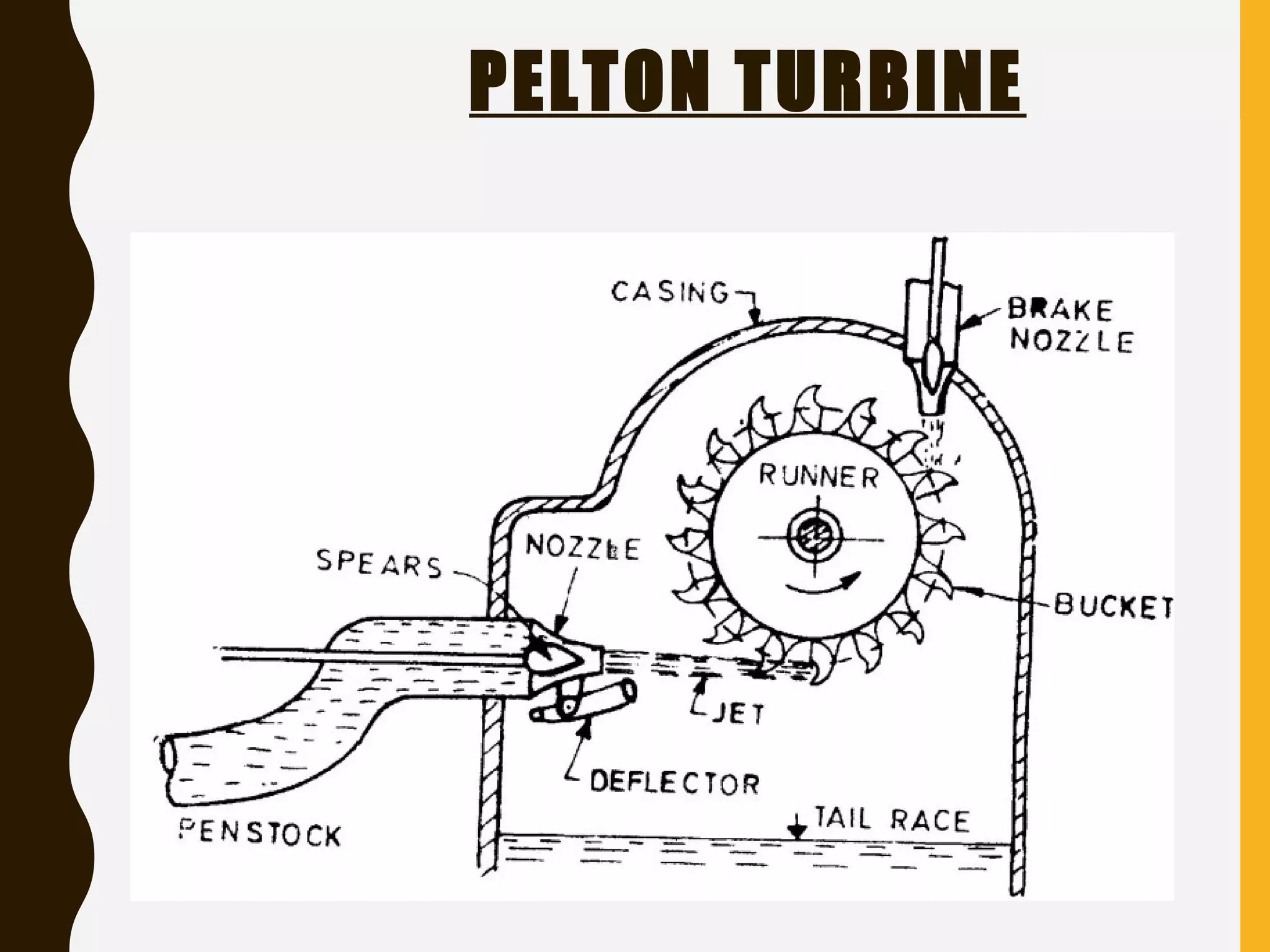
• Theonly type of impulse turbine that is in use these days is Pelton turbine.
It is also called a free jet turbine as it uses a free jet of water under
atmospheric pressure.
• It works under high head and uses less quantity of water. Water from the
reservoir is brought to the turbine through penstocks, at the end of which
a nozzle is fitted. The nozzle converts whole of the available head into the
kinetic head in the form of a high velocity jet.
PELTON TURBINES
• Thejet strikes the buckets mounted on the rim of a wheel called runner.
• A shaft passes through the runner. The force of jet causes the runner to
rotate and mechanical power is produced.
• In the end water goes into the tail race.
• Number of nozzles depends upon specific speed. However, maximum
number of nozzles can be 6.
8.
COMPONENTS OF APELTON
TURBINE
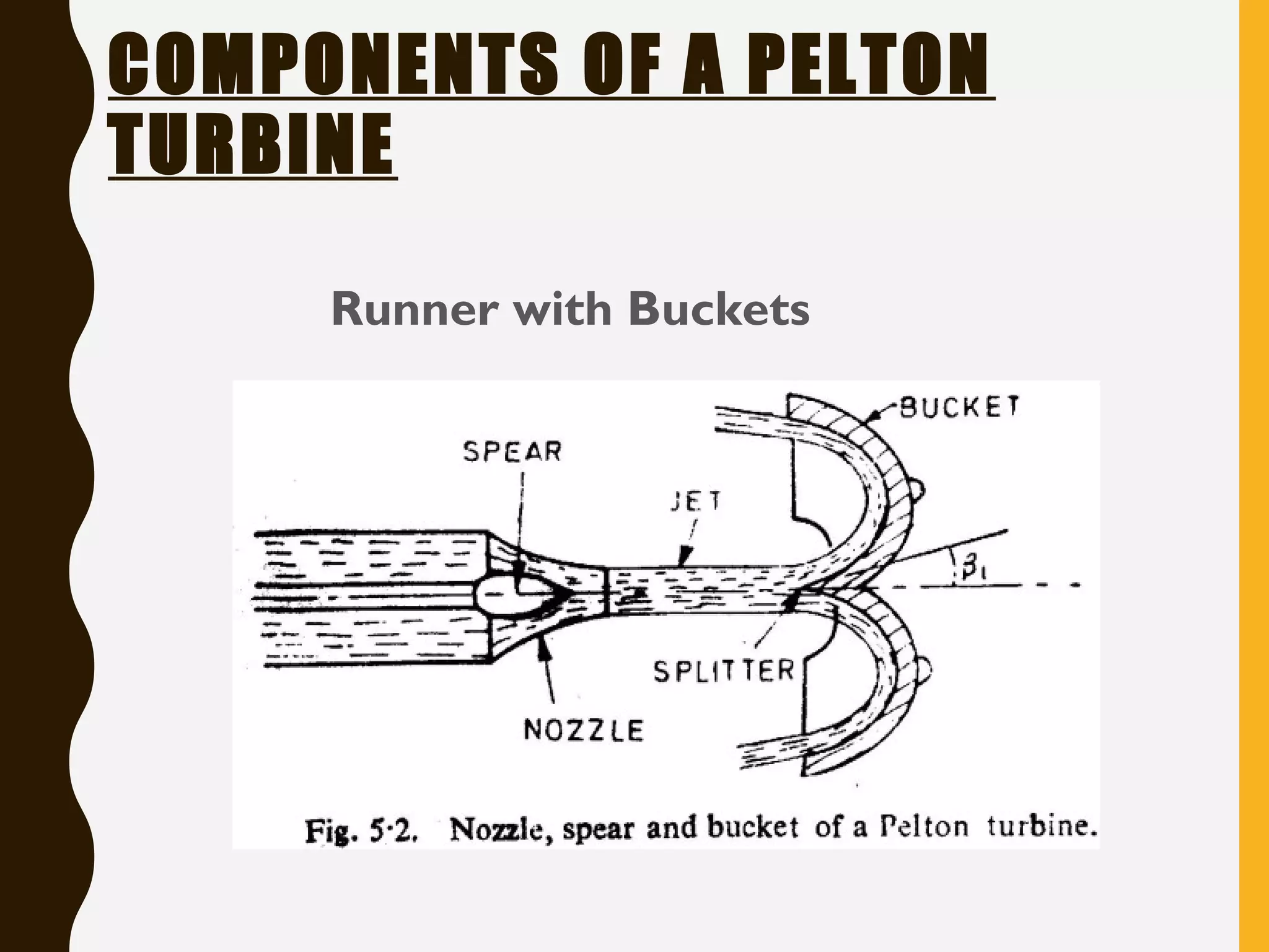
Runner with Buckets
• The runner of a Pelton turbine consists of a number of double cupped
buckets fixed to the periphery of the wheel.
• Each bucket has a sharp edge at the center called the splitter
• The jet strikes each bucket at this splitter and is divided into two sides,
thus avoiding any unbalanced thrust on the shaft.
• As the splitter takes the full impact of the jet, so it has to be quite strong.
COMPONENTS OF APELTON
TURBINE
Nozzle with guide mechanism
• The function of the nozzle of a Pelton wheel is to convert the available
pressure energy into high velocity energy in the form of jet.
• The quantity of water required is proportional to the load on the turbine.
Therefore, to control the flow through the nozzle, some sort of a
regulating or a governing mechanism is necessary. This is generally done by
using a spear inside the nozzle. The movement of spear inside the nozzle
changes the area of flow through it, thus varying the discharge.
11.
COMPONENTS OF APELTON
TURBINE
Nozzle with guide mechanism
• The nozzle is usually made of either cast iron or cast steel.
• Sometimes, a small brake nozzle is also used in case of large turbine
When the wheel is to stopped, besides cutting off the supply of wate
through the main nozzle, the brake nozzle also directs the water on to th
back of buckets to bring the wheel quickly to rest.
12.
COMPONENTS OF APELTON
TURBINE
Casing
• The casing is not to perform any hydraulic function.
• However, a casing is necessary to avoid accidents, splashing of water, to
lead the water to the tailrace and to support the hosing for the bearing and
the nozzle.
• Material for the casing is usually cast iron.
13.
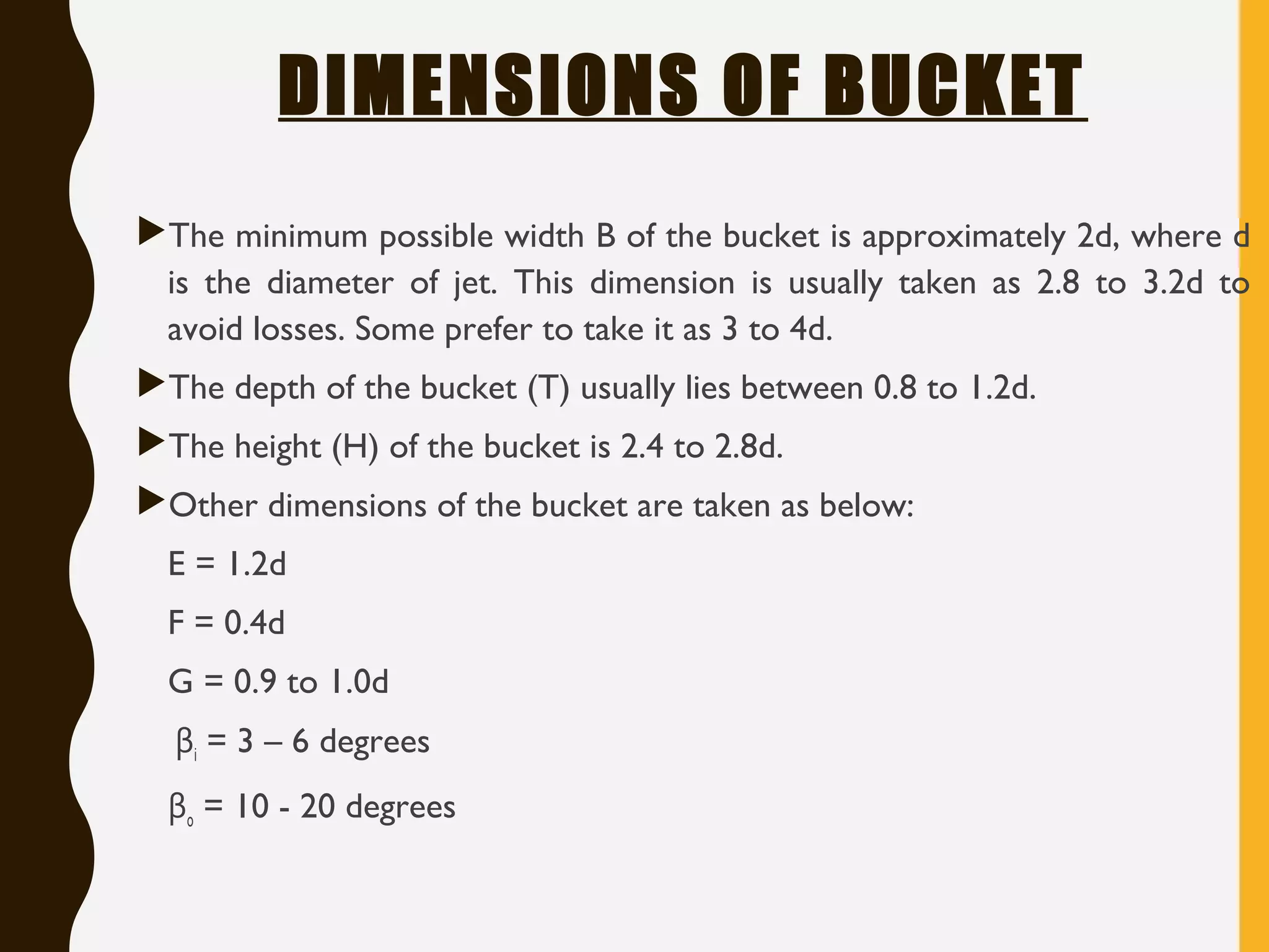
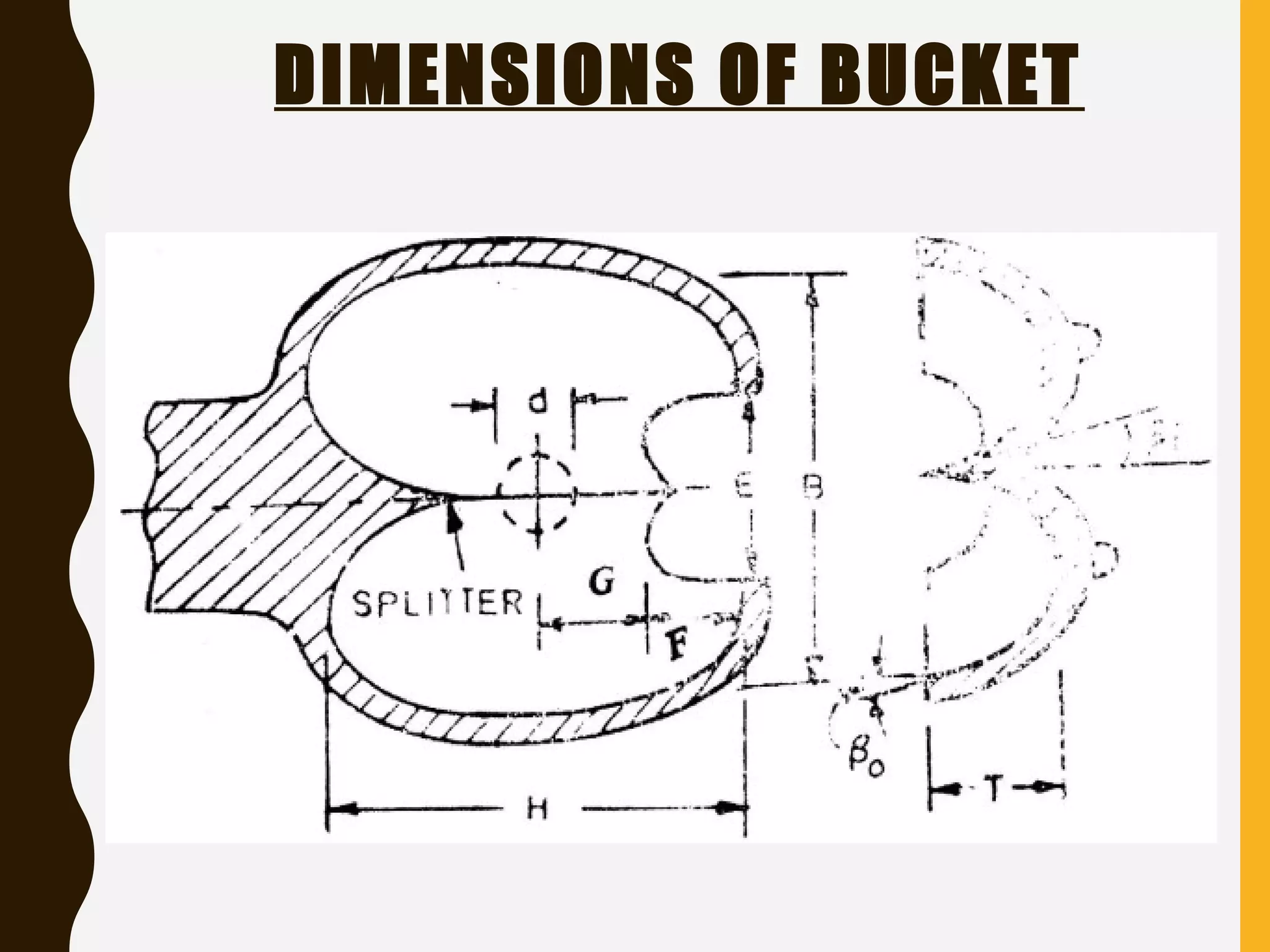
DIMENSIONS OF BUCKET
Theminimum possible width B of the bucket is approximately 2d, where d
is the diameter of jet. This dimension is usually taken as 2.8 to 3.2d to
avoid losses. Some prefer to take it as 3 to 4d.
The depth of the bucket (T) usually lies between 0.8 to 1.2d.
The height (H) of the bucket is 2.4 to 2.8d.
Other dimensions of the bucket are taken as below:
E = 1.2d
F = 0.4d
G = 0.9 to 1.0d
βi = 3 – 6 degrees
βo = 10 - 20 degrees
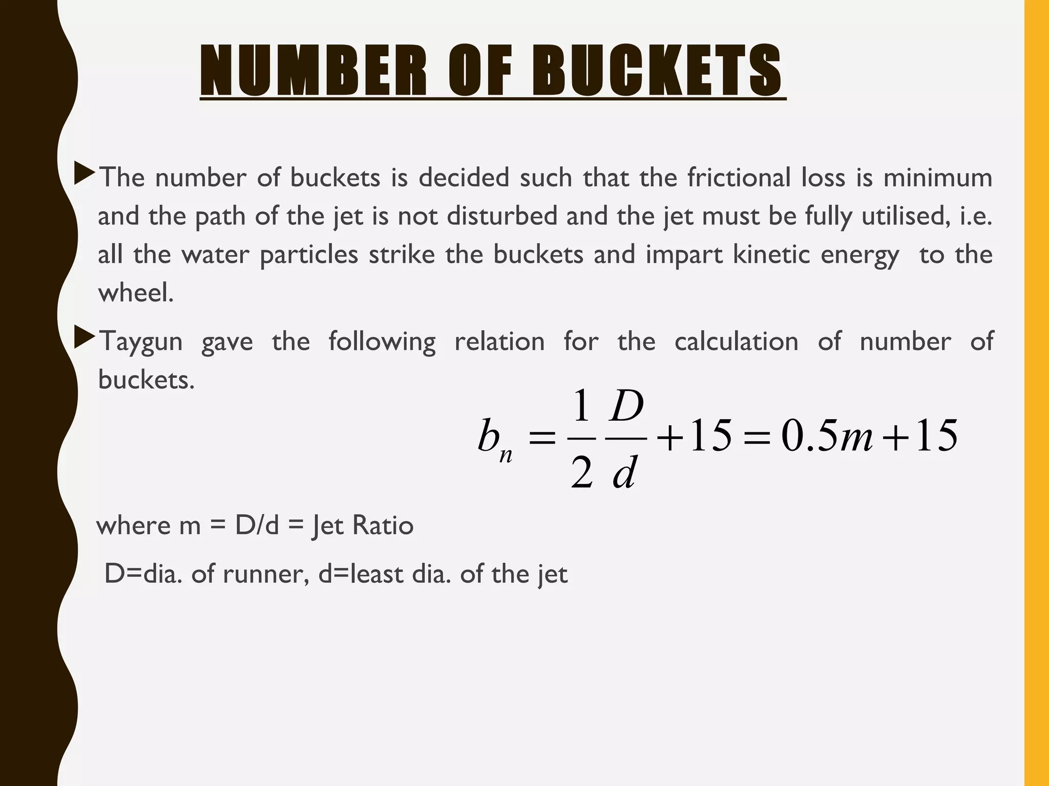
NUMBER OF BUCKETS
Thenumber of buckets is decided such that the frictional loss is minimum
and the path of the jet is not disturbed and the jet must be fully utilised, i.e.
all the water particles strike the buckets and impart kinetic energy to the
wheel.
Taygun gave the following relation for the calculation of number of
buckets.
where m = D/d = Jet Ratio
D=dia. of runner, d=least dia. of the jet
155.015
2
1
+=+= m
d
D
bn
16.
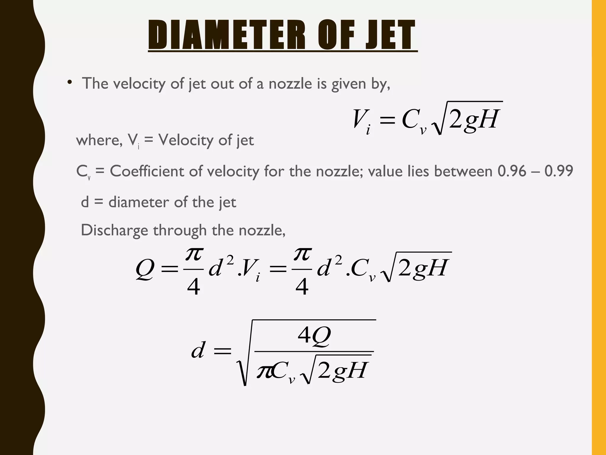
DIAMETER OF JET
•The velocity of jet out of a nozzle is given by,
where, Vi = Velocity of jet
Cv = Coefficient of velocity for the nozzle; value lies between 0.96 – 0.99
d = diameter of the jet
Discharge through the nozzle,
gHCV vi 2=
gHCdVdQ vi 2.
4
.
4
22 ππ
==
gHC
Q
d
v 2
4
π
=
17.
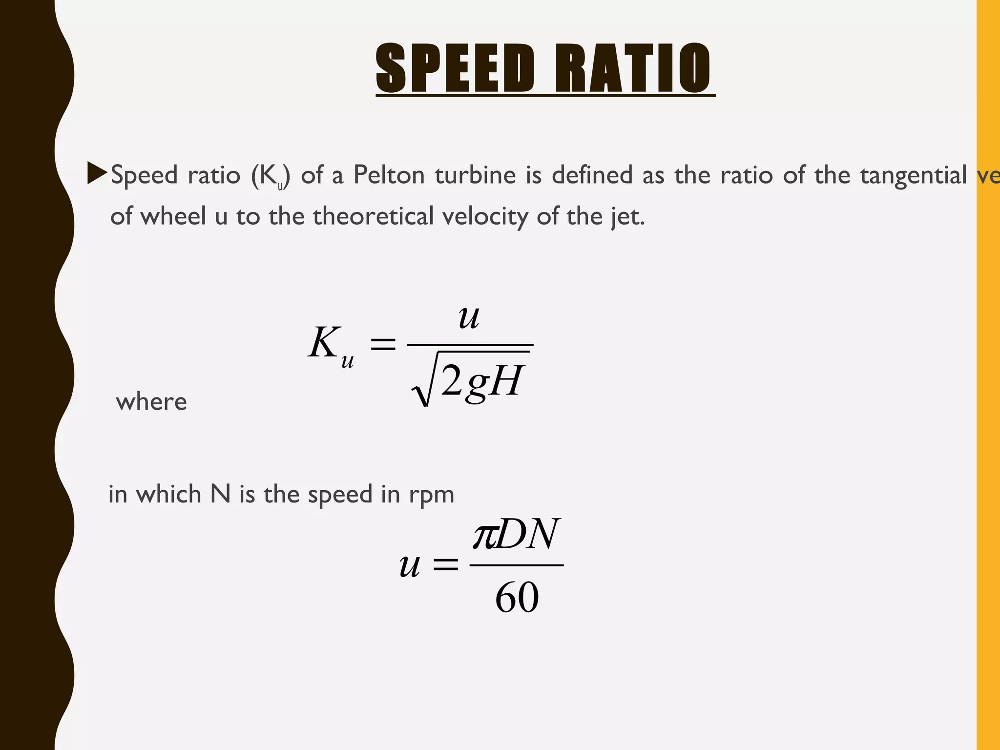
SPEED RATIO
Speed ratio(Ku) of a Pelton turbine is defined as the ratio of the tangential ve
of wheel u to the theoretical velocity of the jet.
where
in which N is the speed in rpm
gH
u
Ku
2
=
60
DN
u
π
=
18.
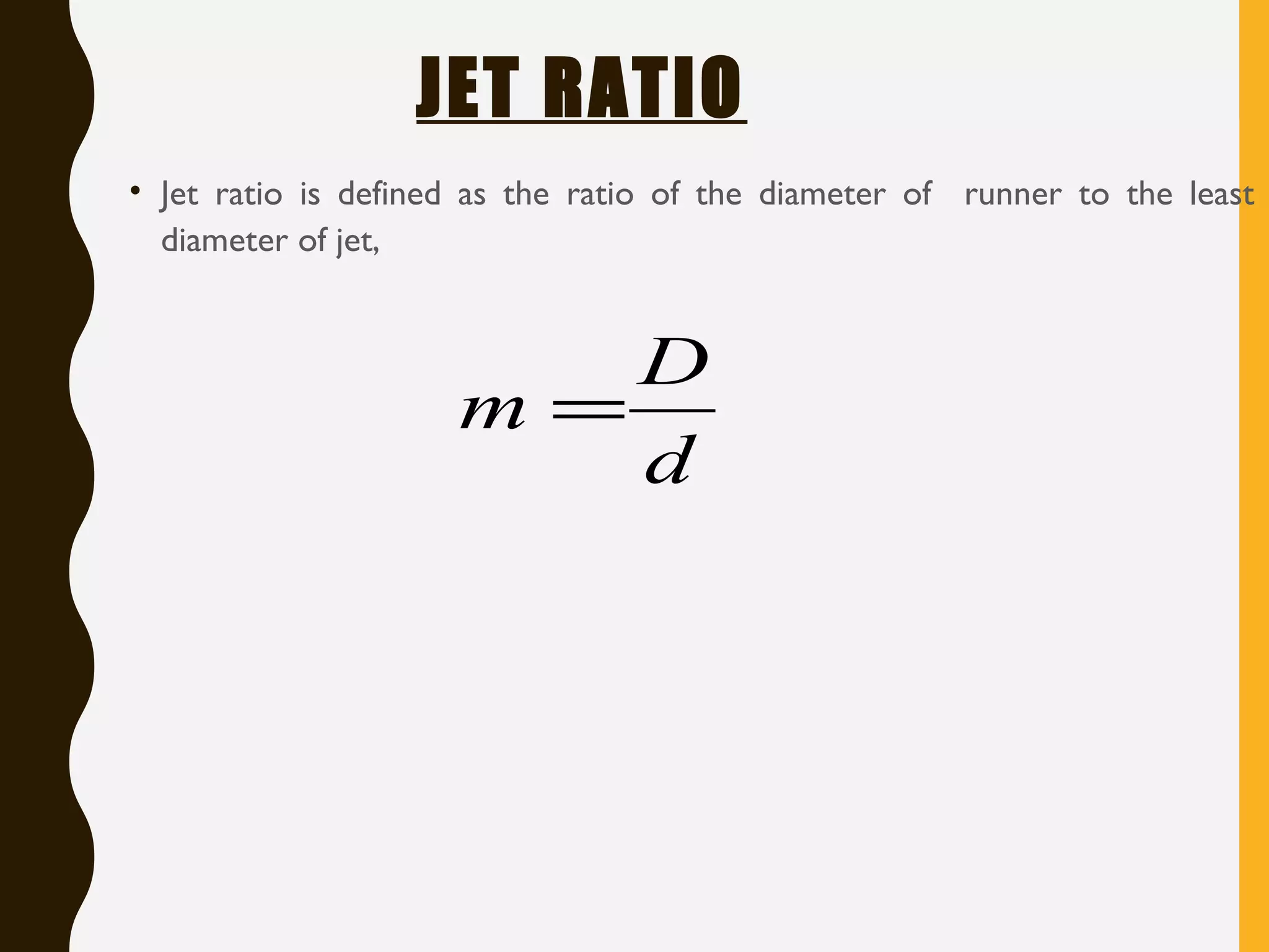
JET RATIO
• Jetratio is defined as the ratio of the diameter of runner to the least
diameter of jet,
d
D
m =
19.
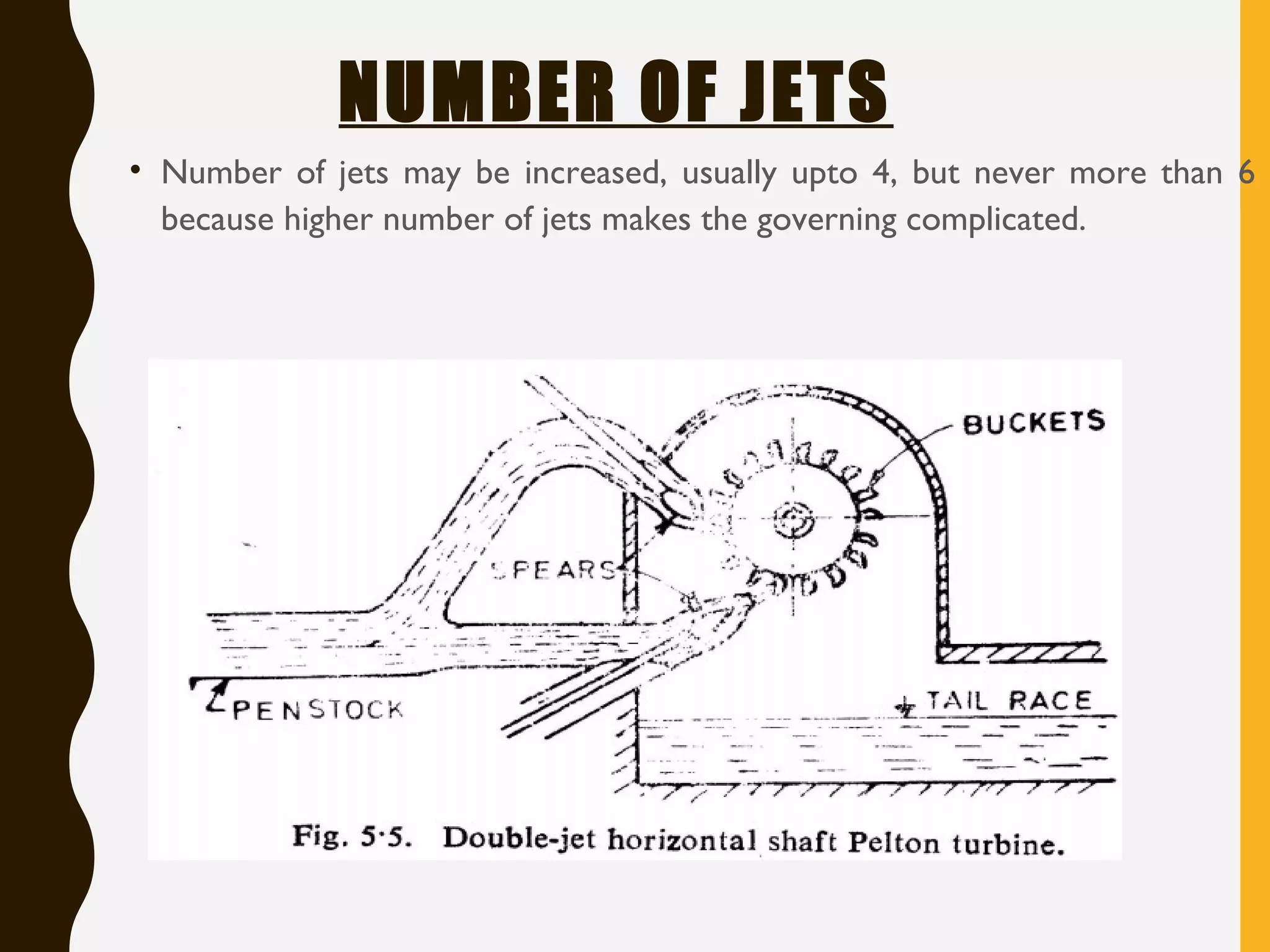
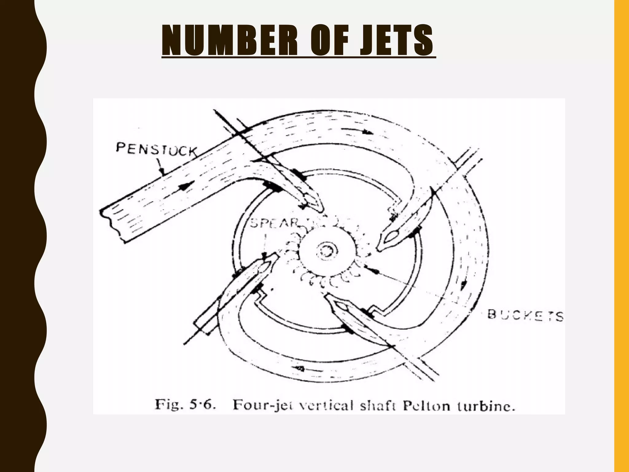
NUMBER OF JETS
•Number of jets may be increased, usually upto 4, but never more than 6
because higher number of jets makes the governing complicated.