Download as PDF, PPTX
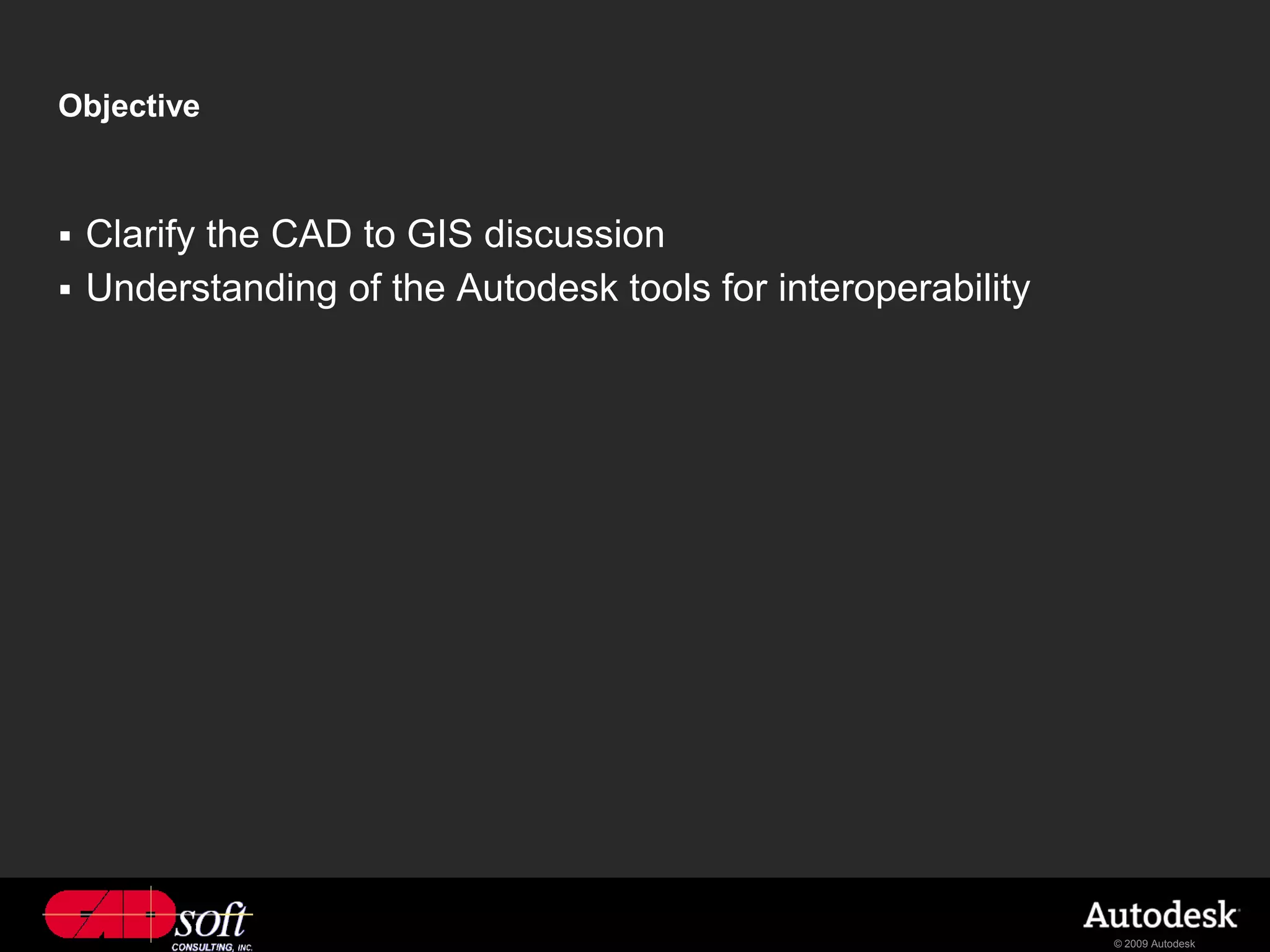
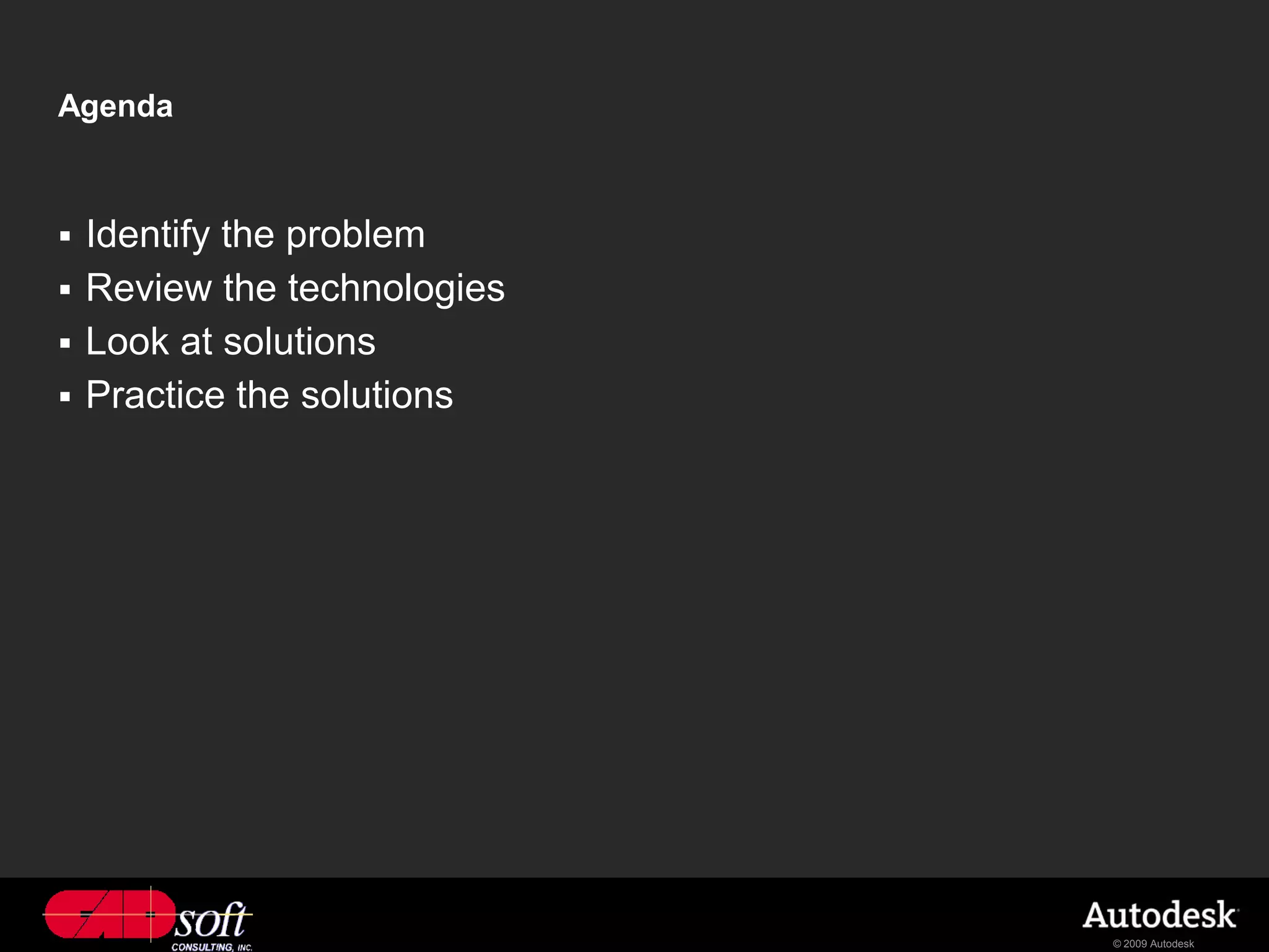


The document discusses harnessing the integrated power of AutoCAD Map 3D and ESRI software through Autodesk's interoperability tools. It introduces Richard Chappell, a geospatial application engineer, and outlines the objective to clarify the CAD to GIS discussion and understand Autodesk's interoperability solutions. The agenda includes identifying issues with CAD and GIS integration, reviewing the technologies, examining solutions, and practicing the solutions.


