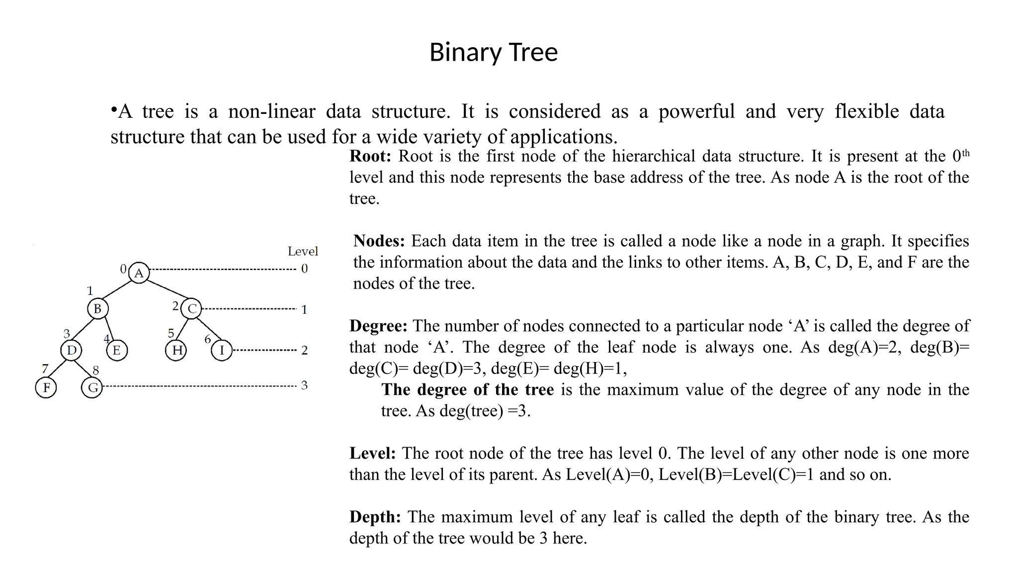
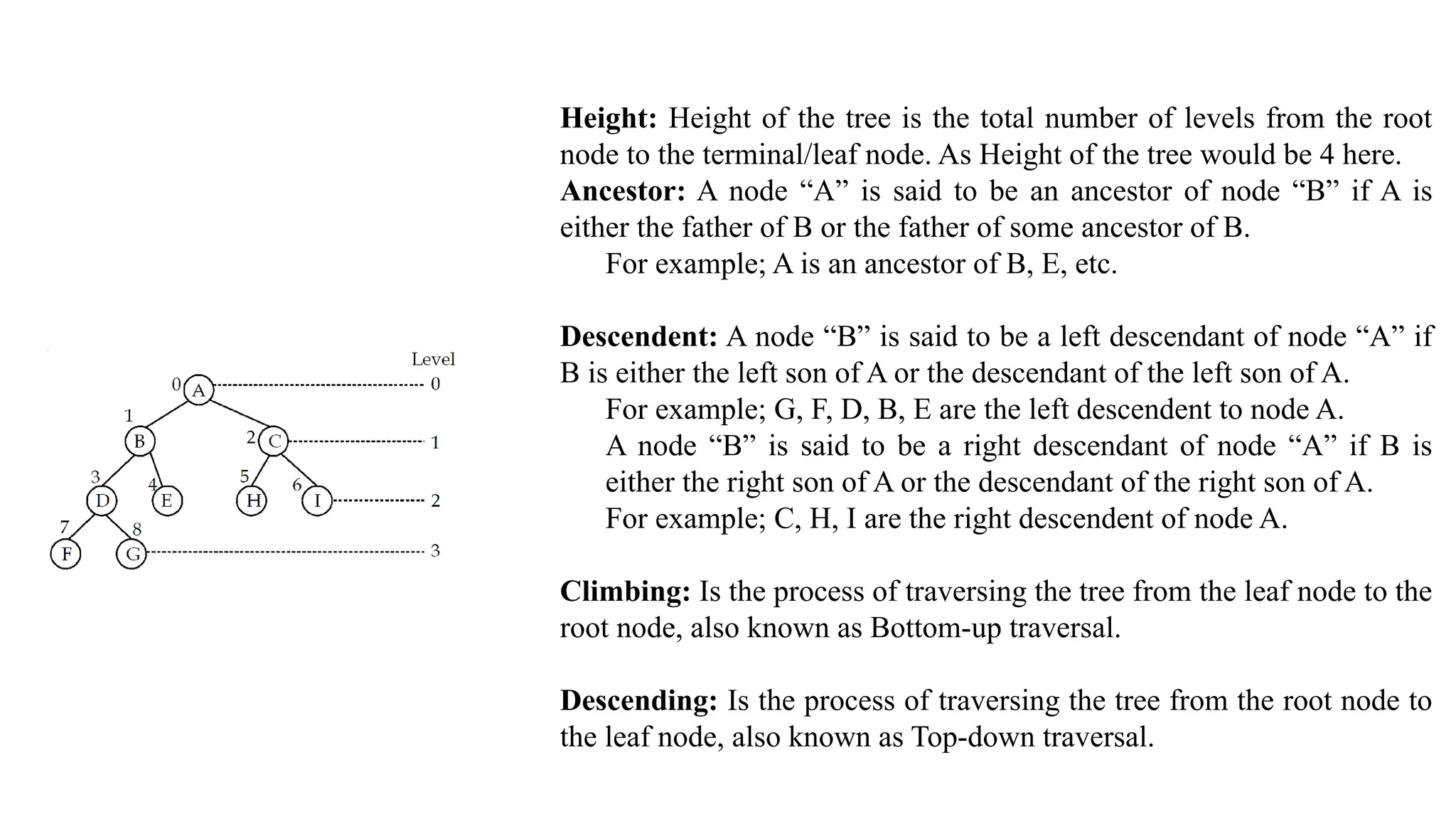
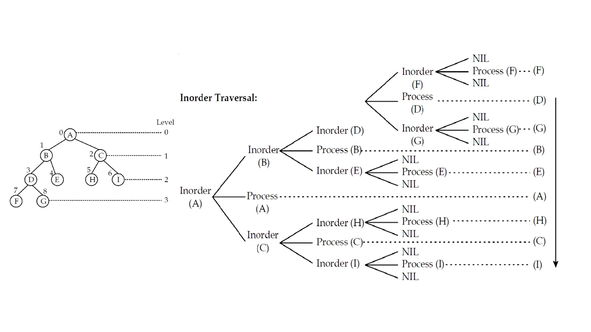
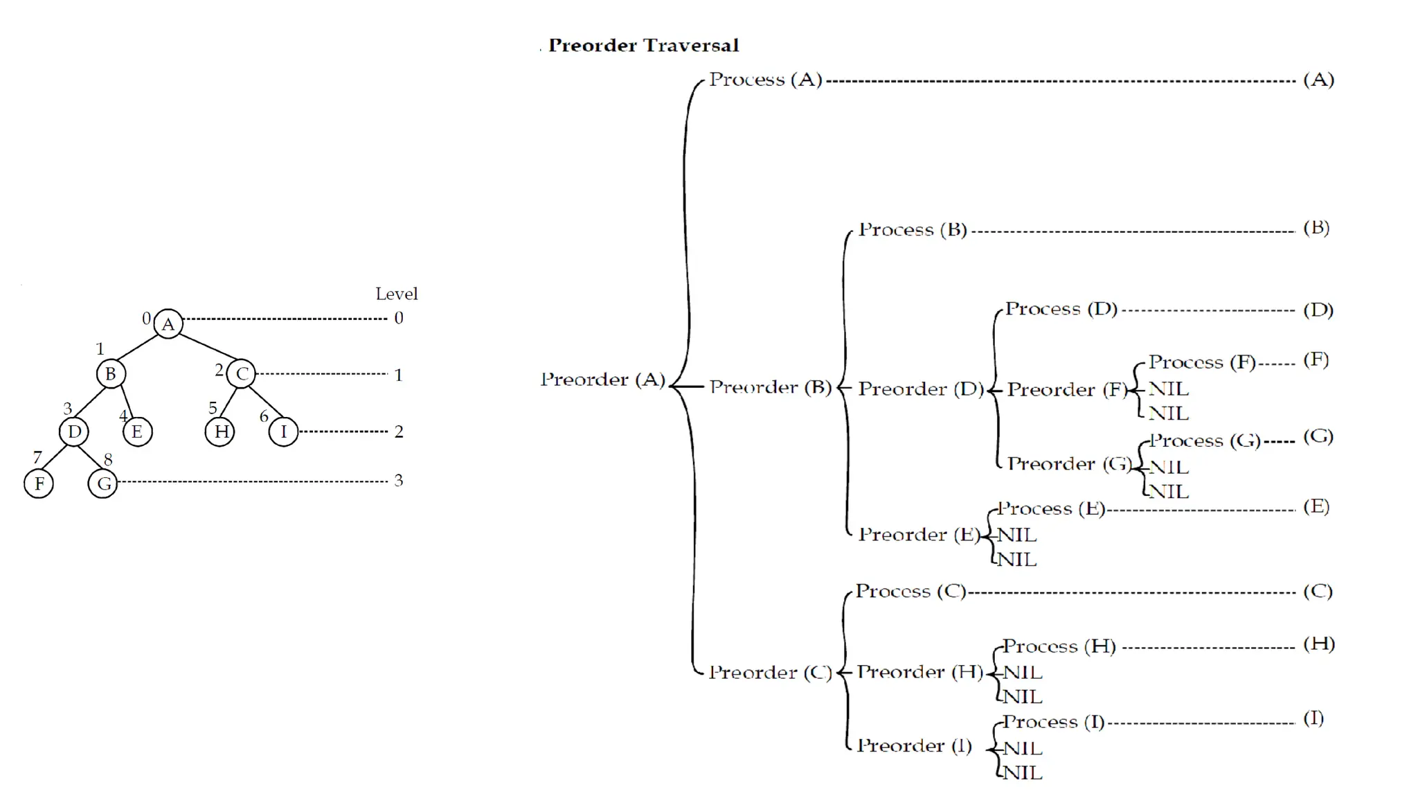
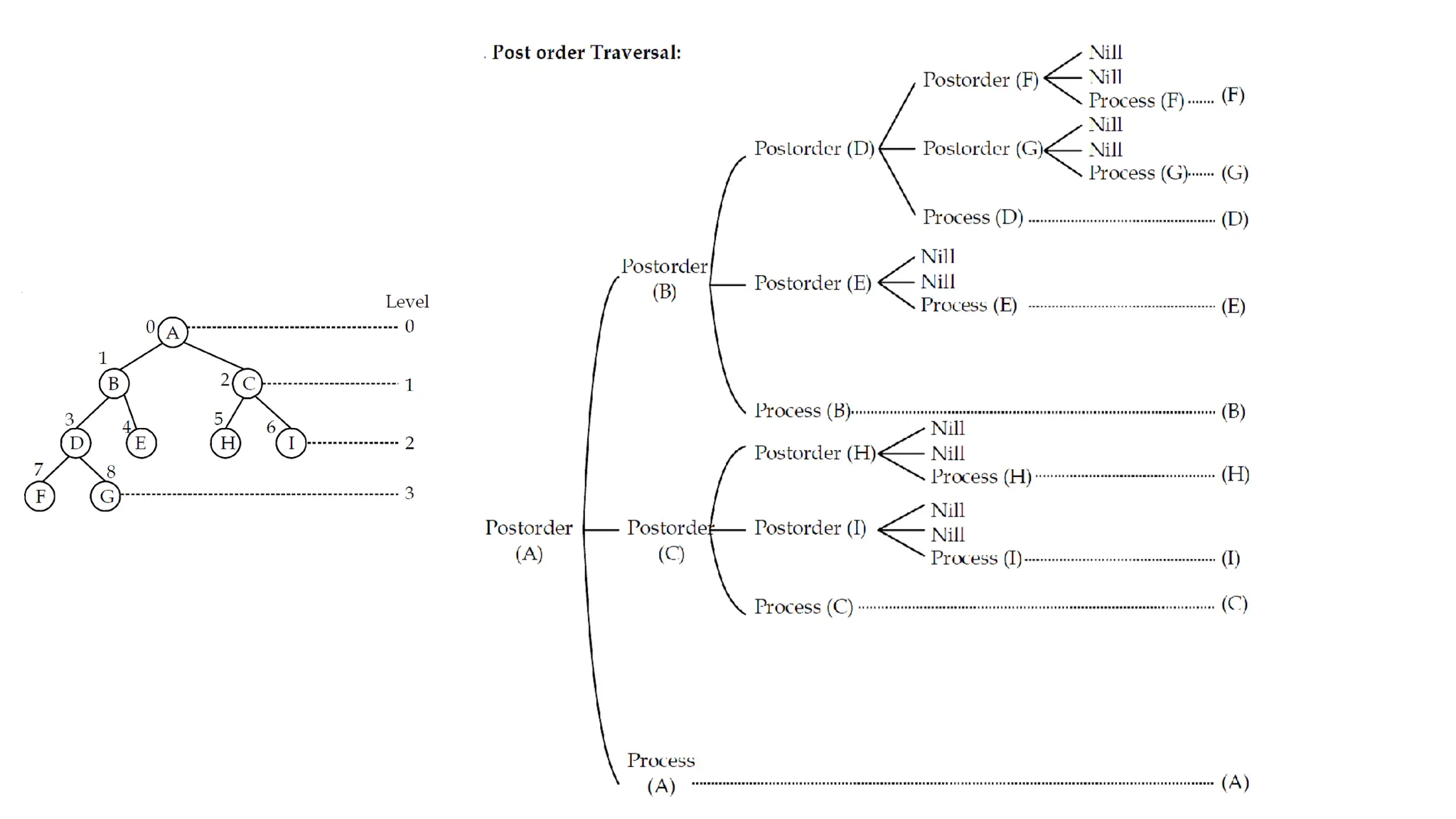
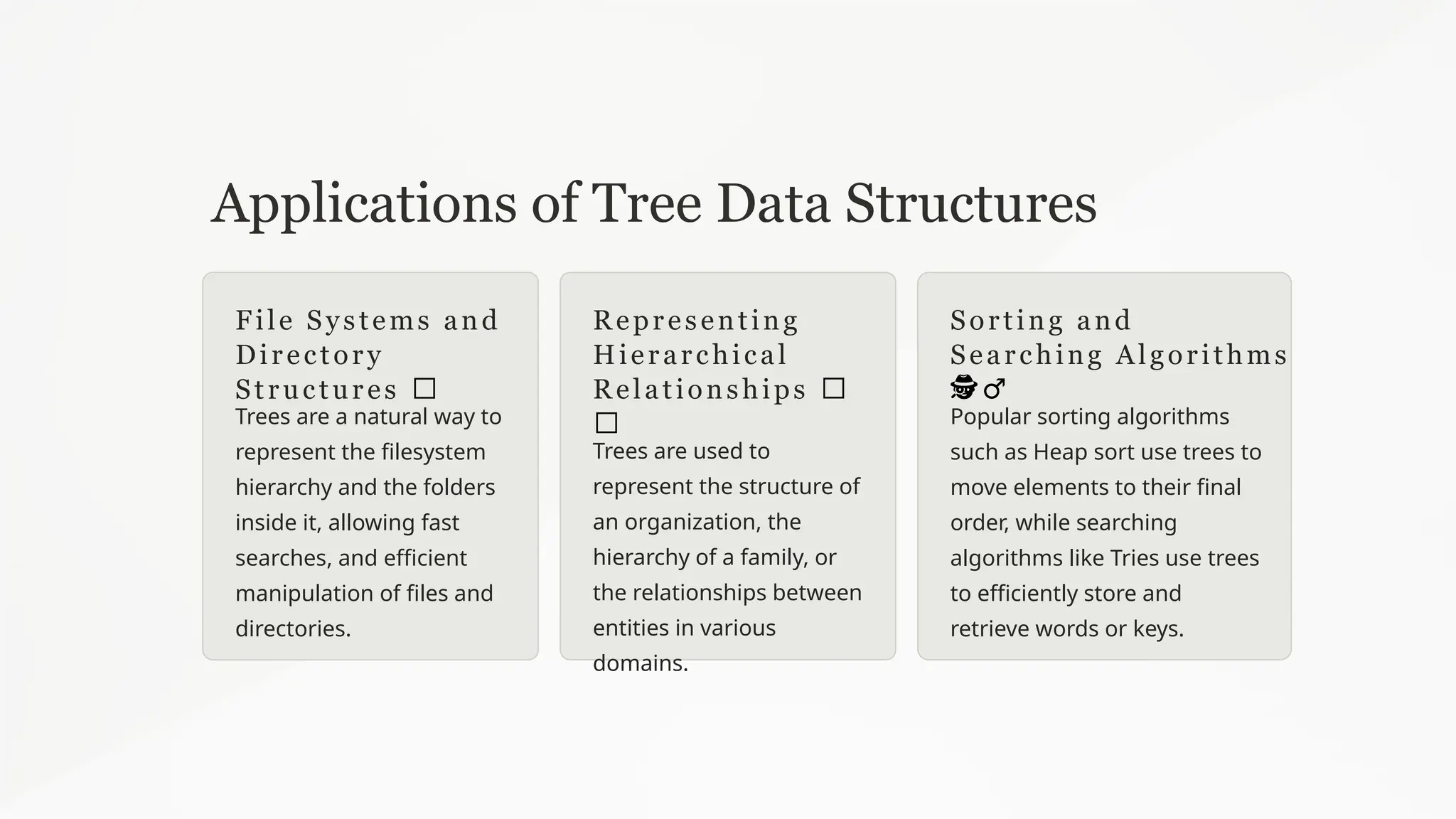
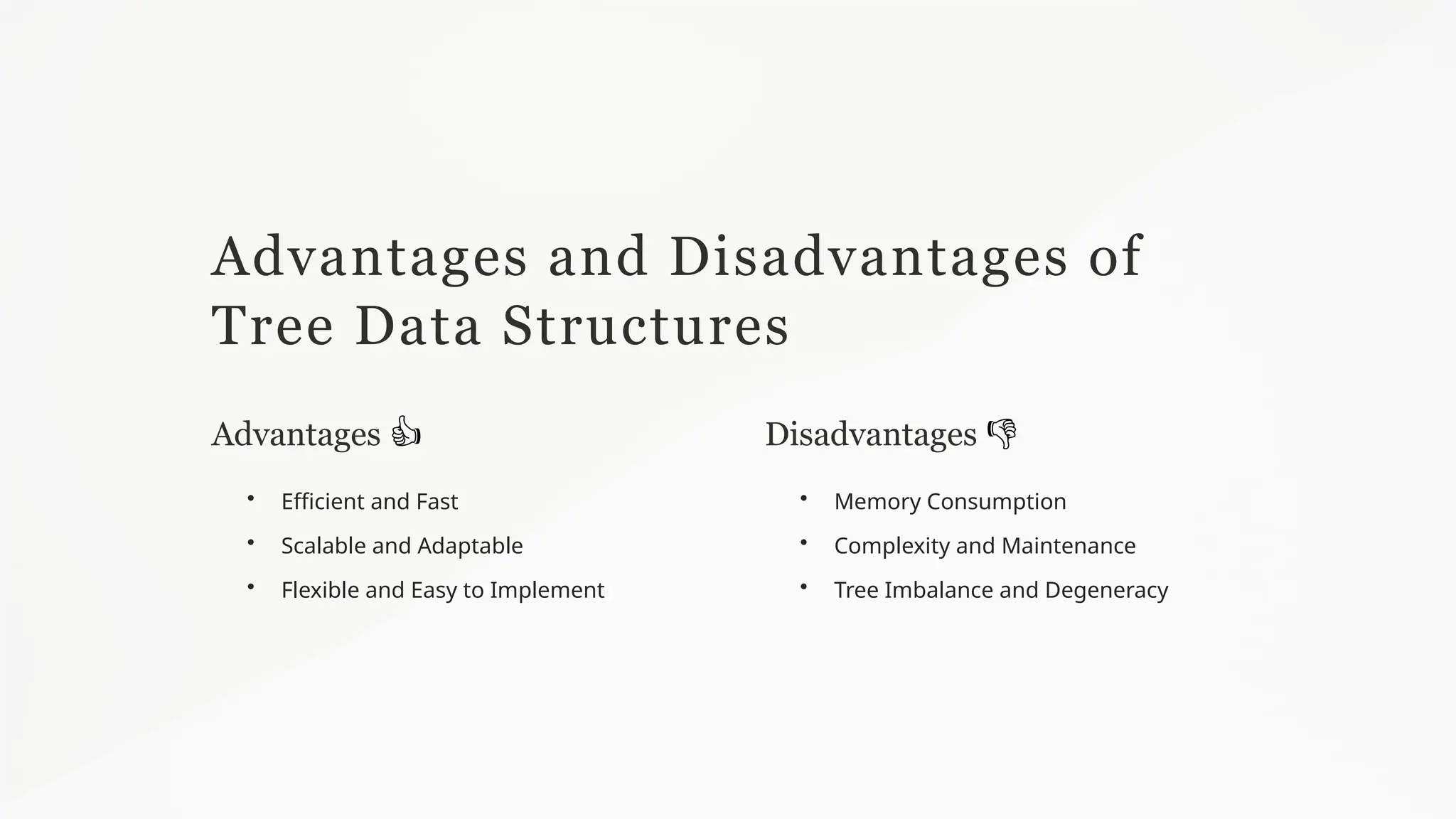
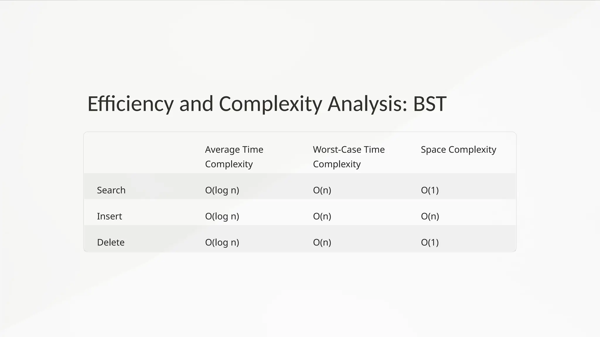
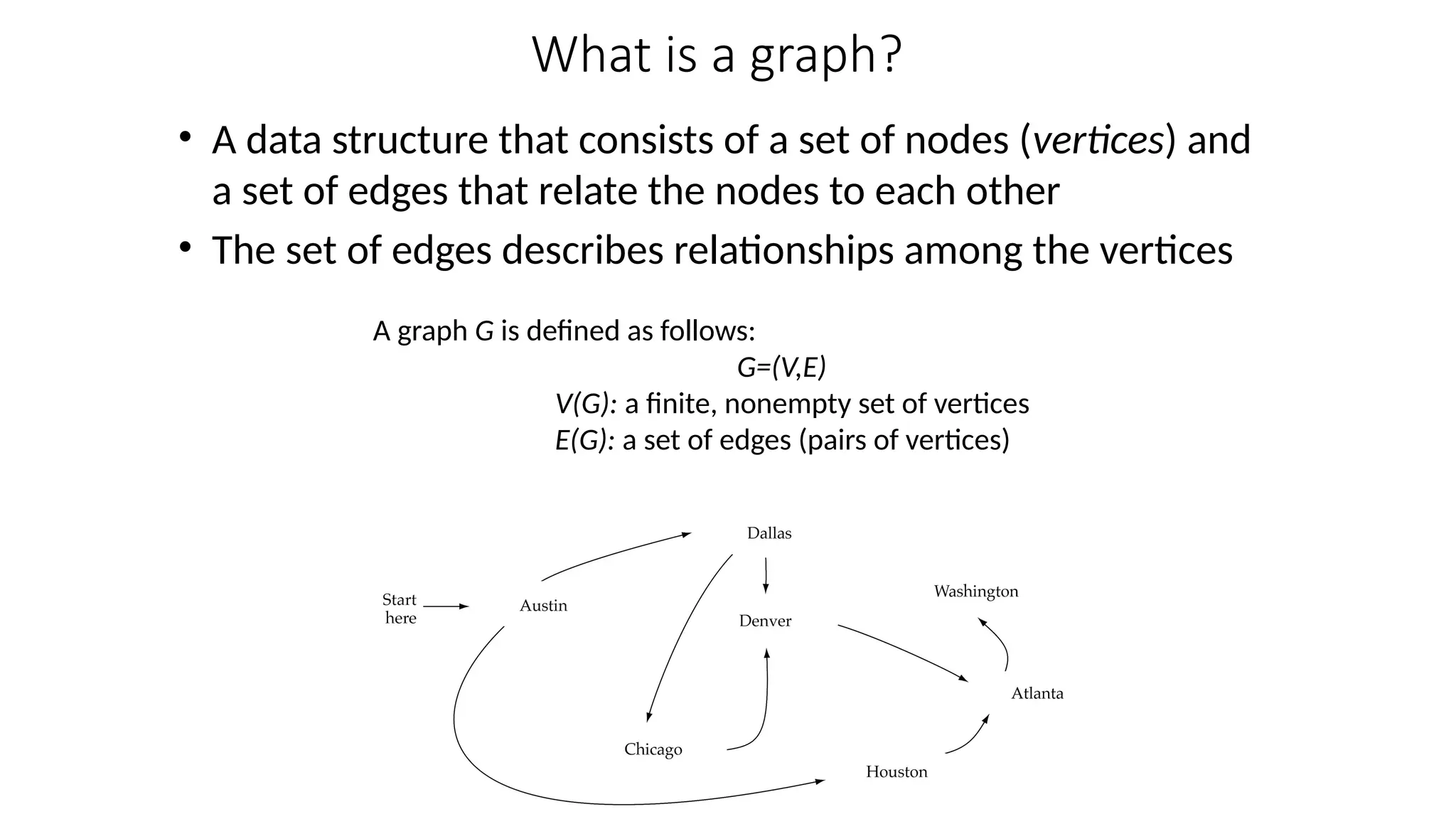
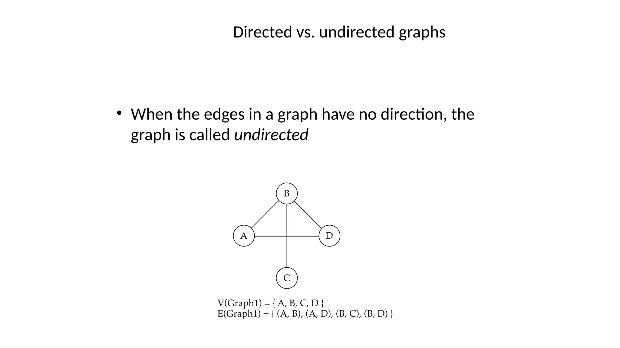
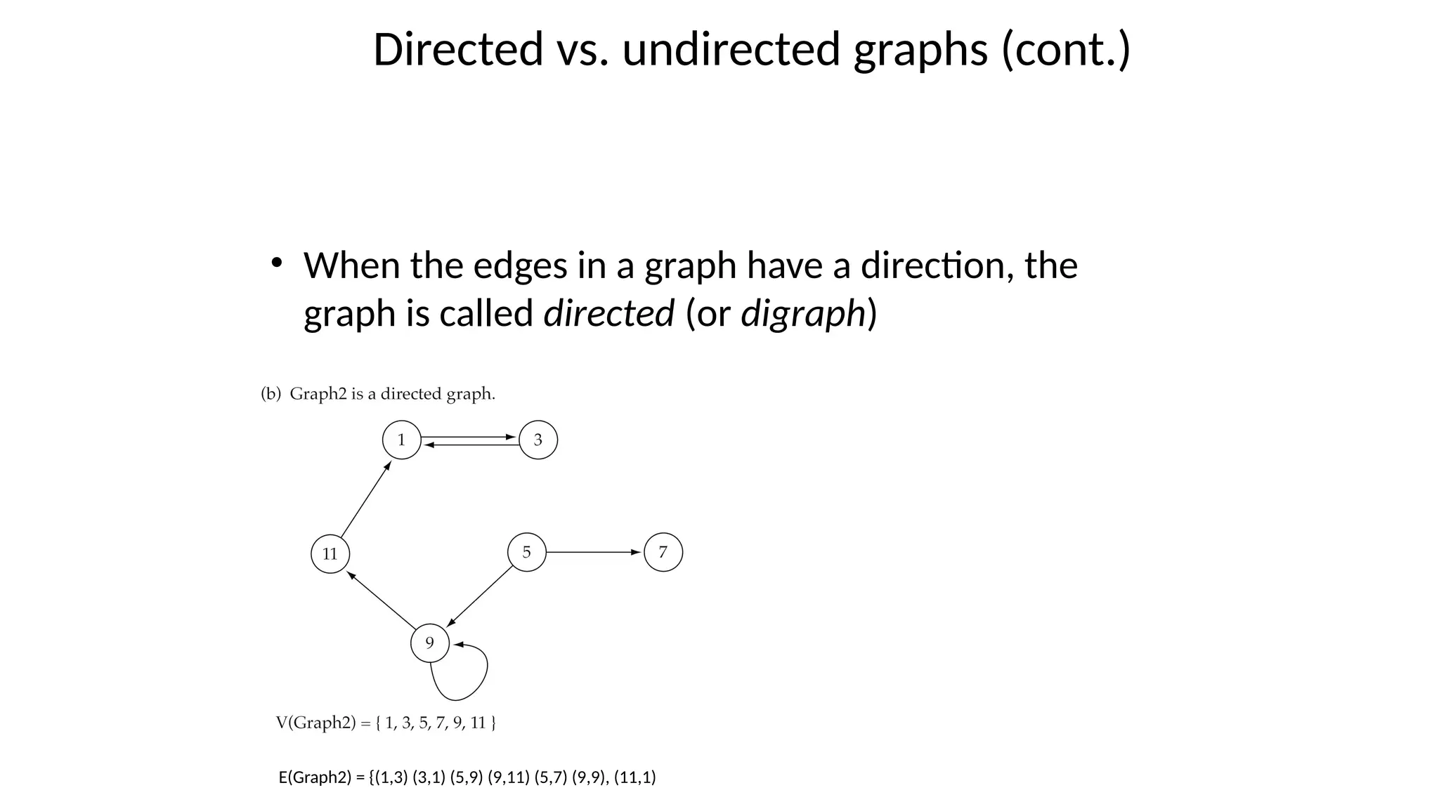
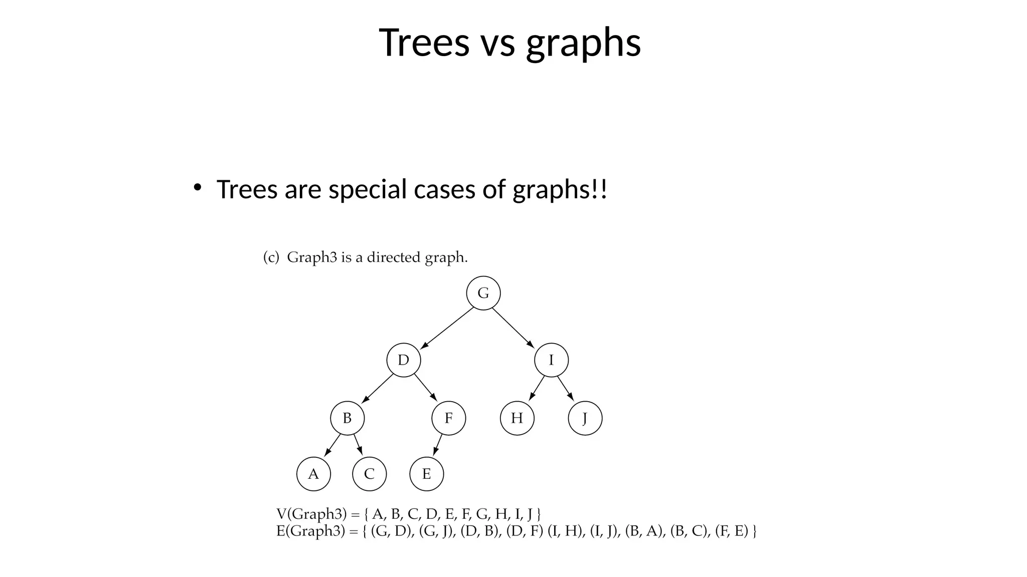
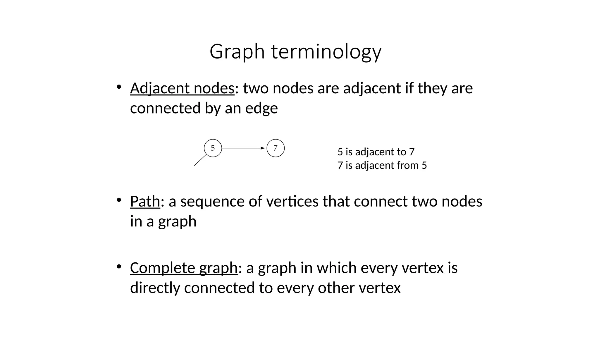
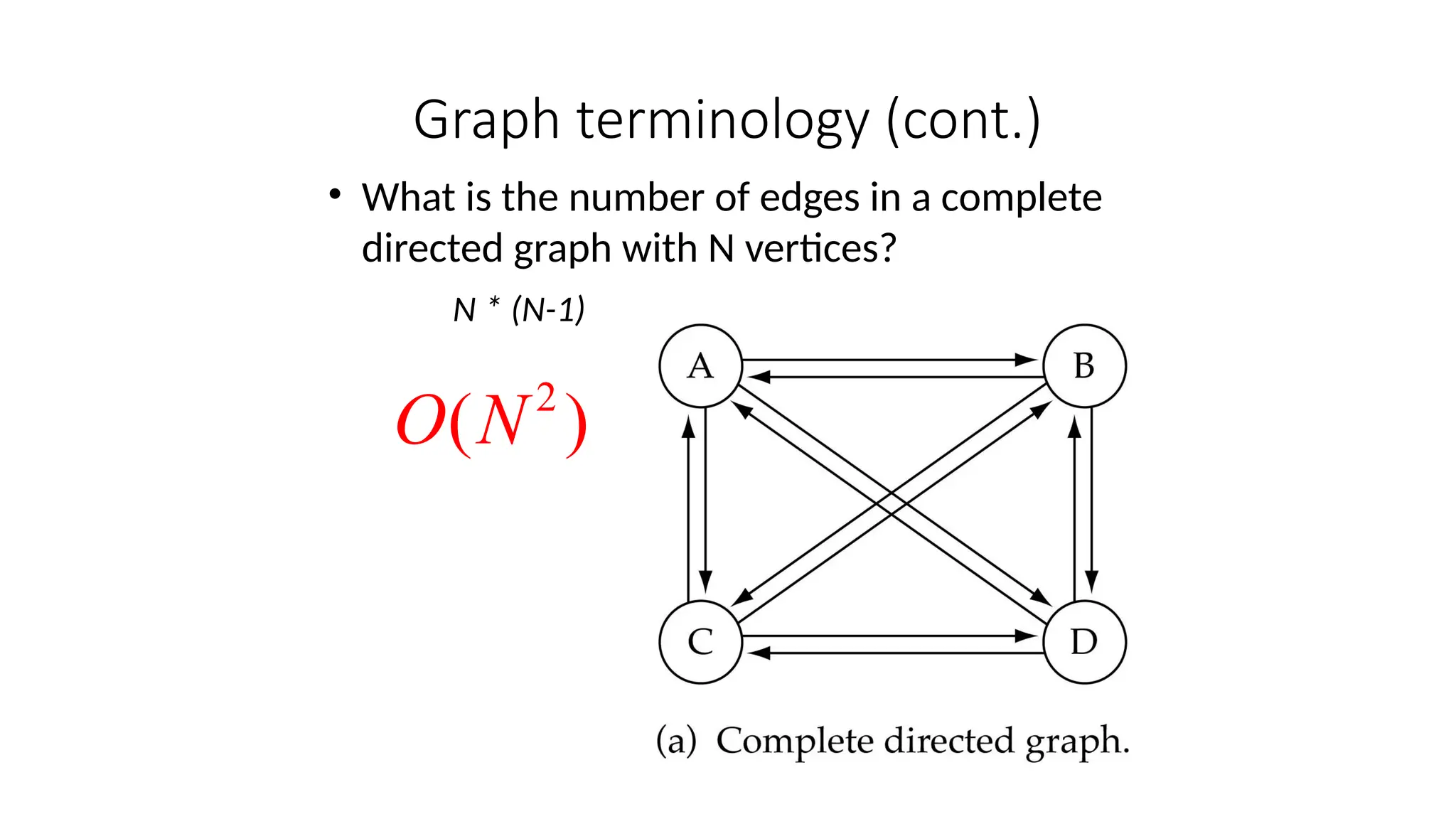
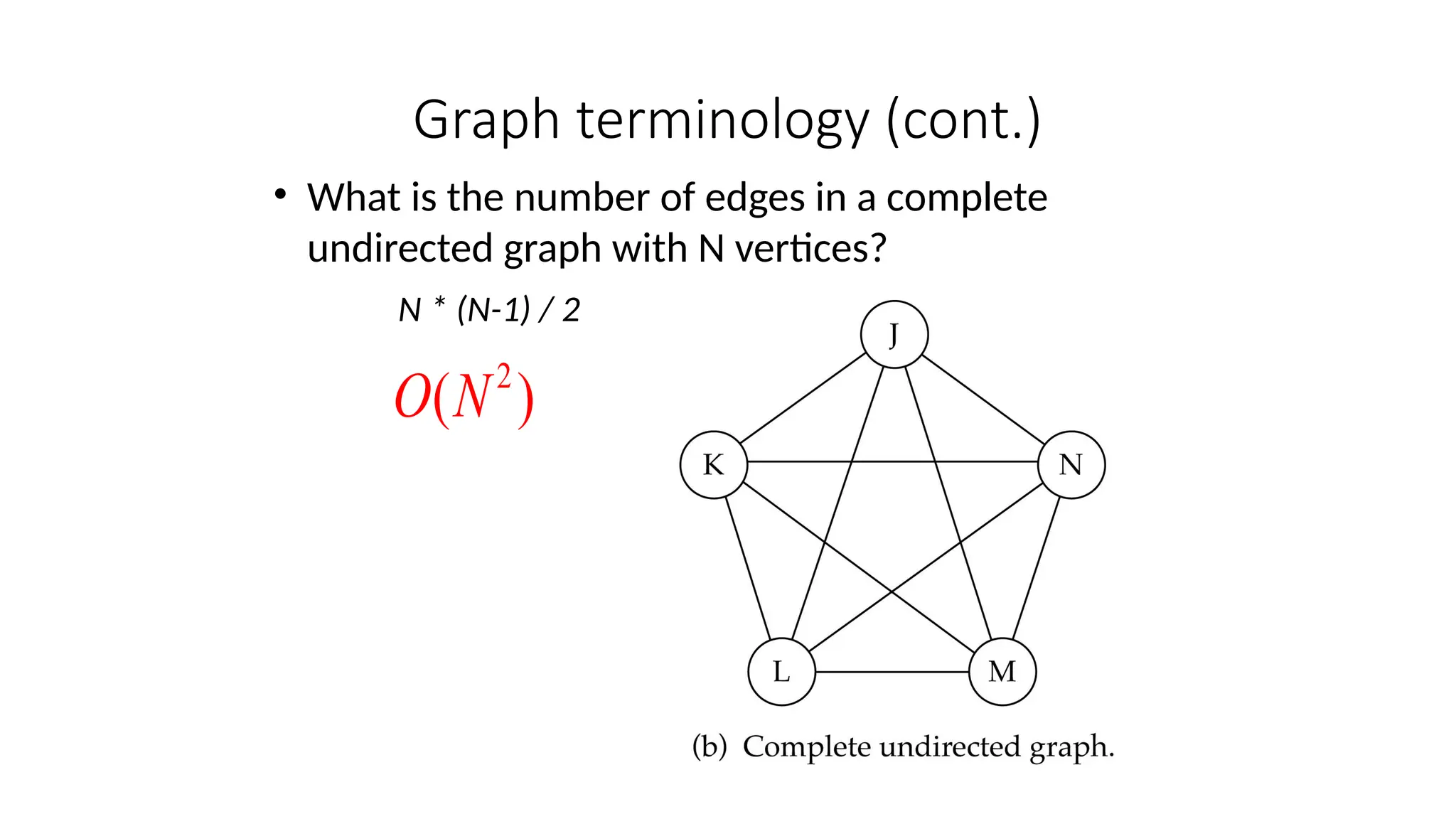
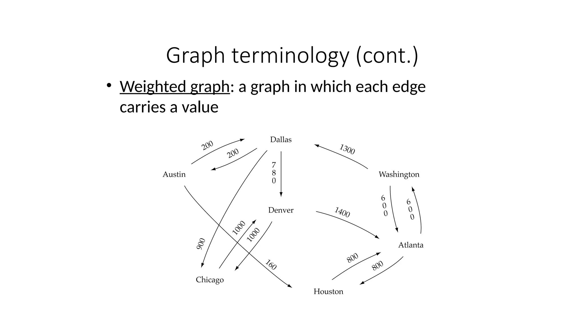
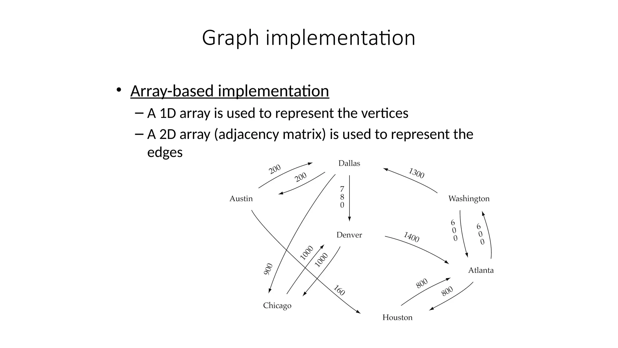
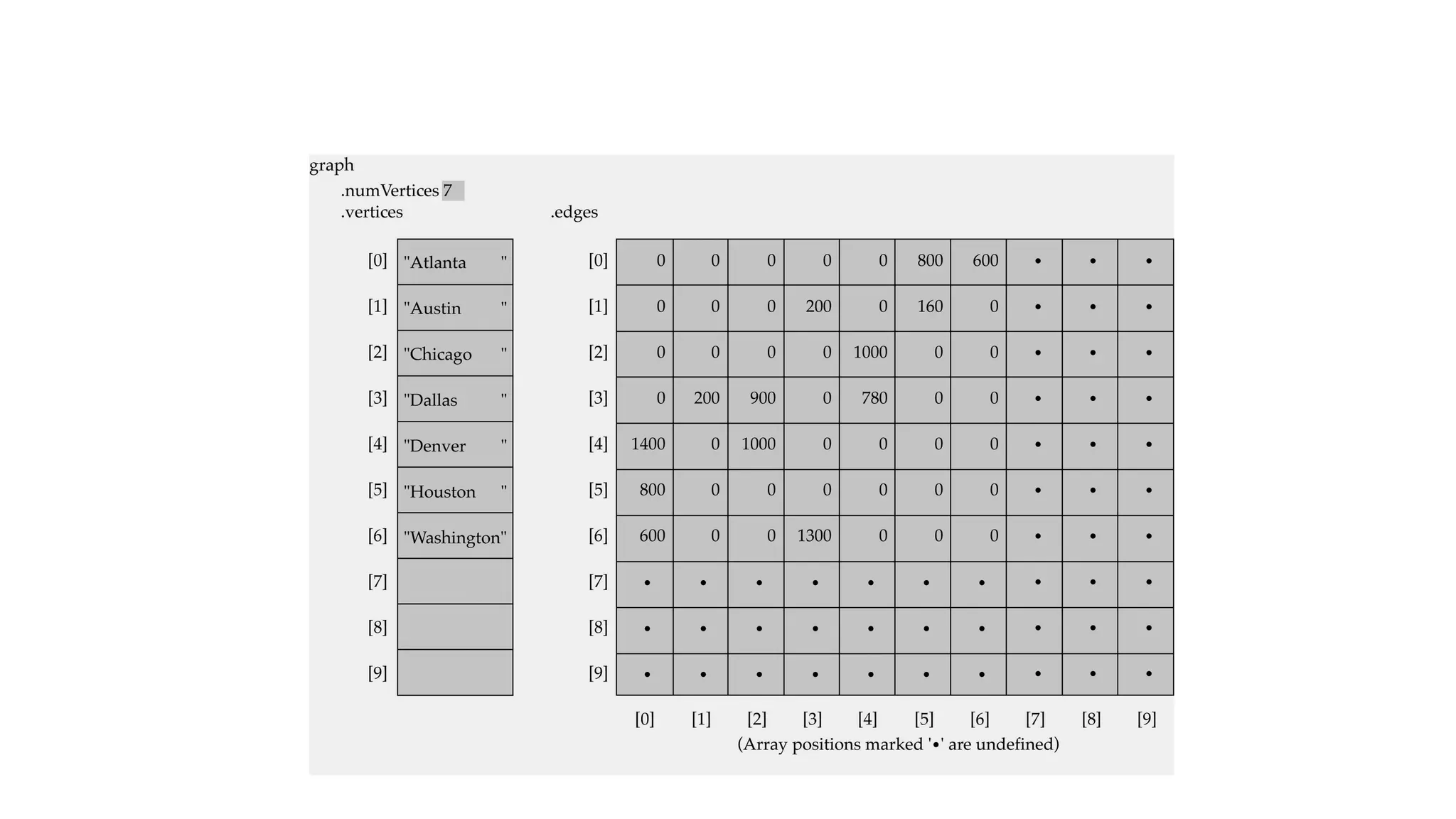
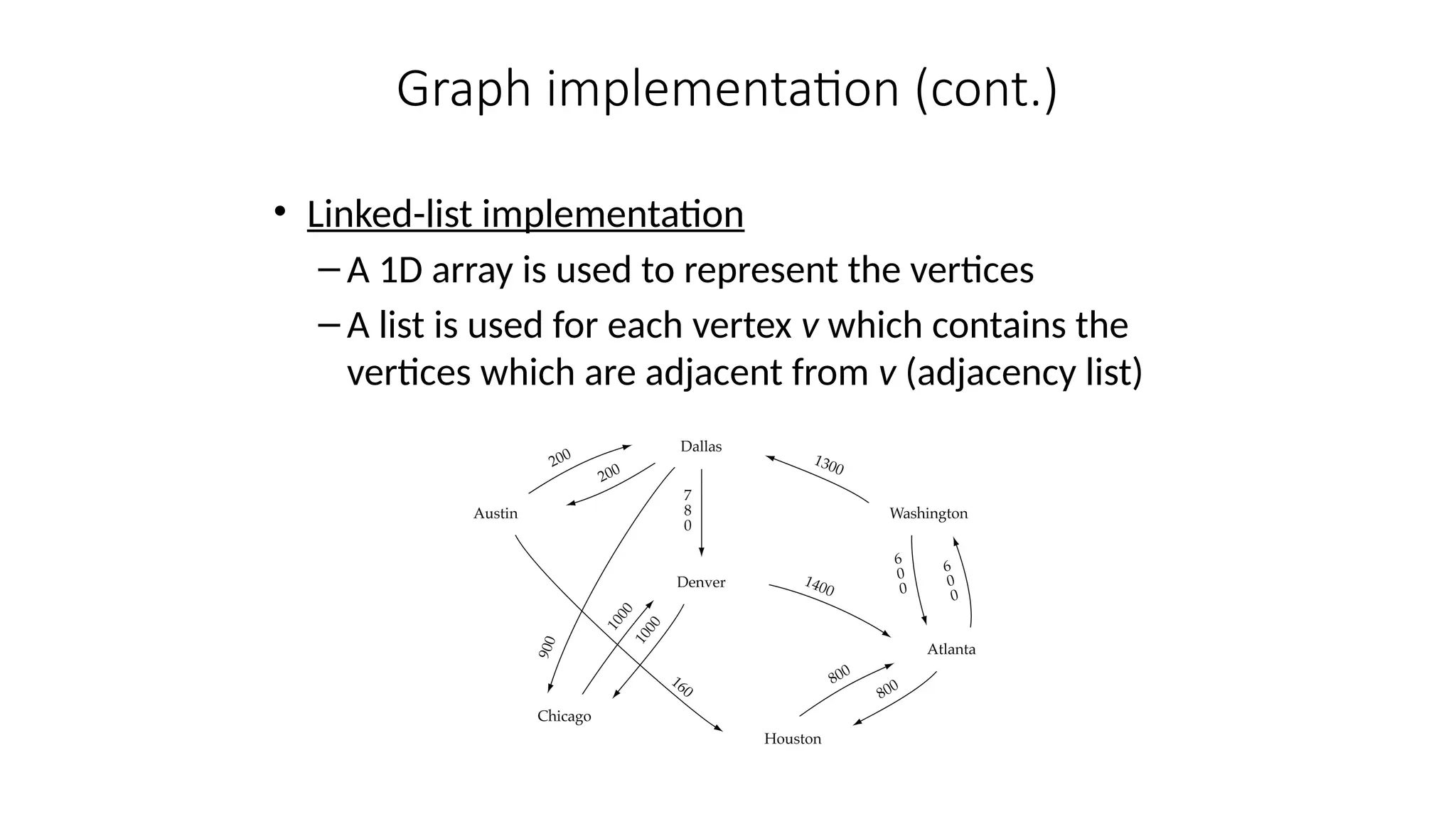
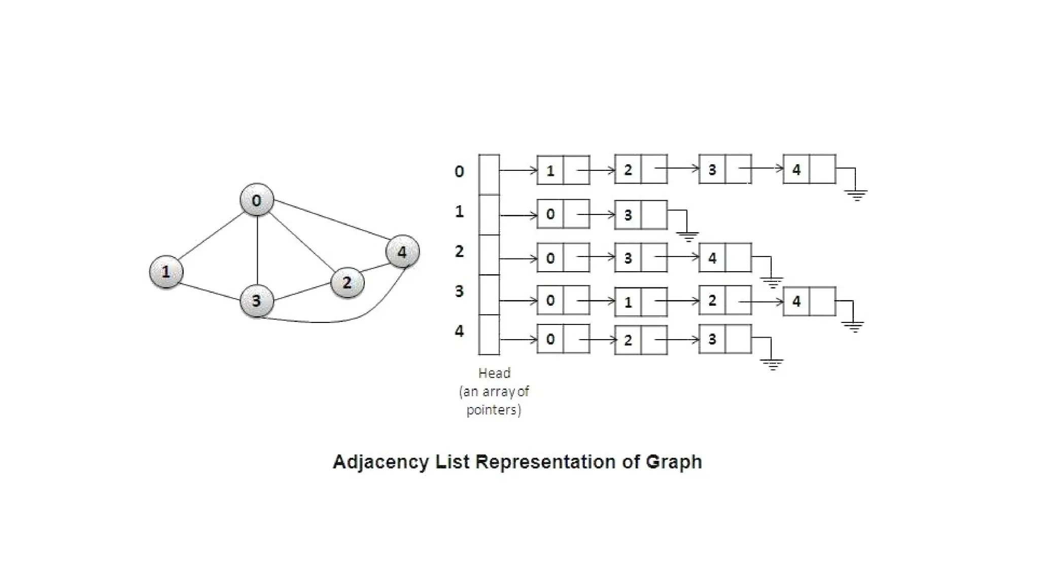
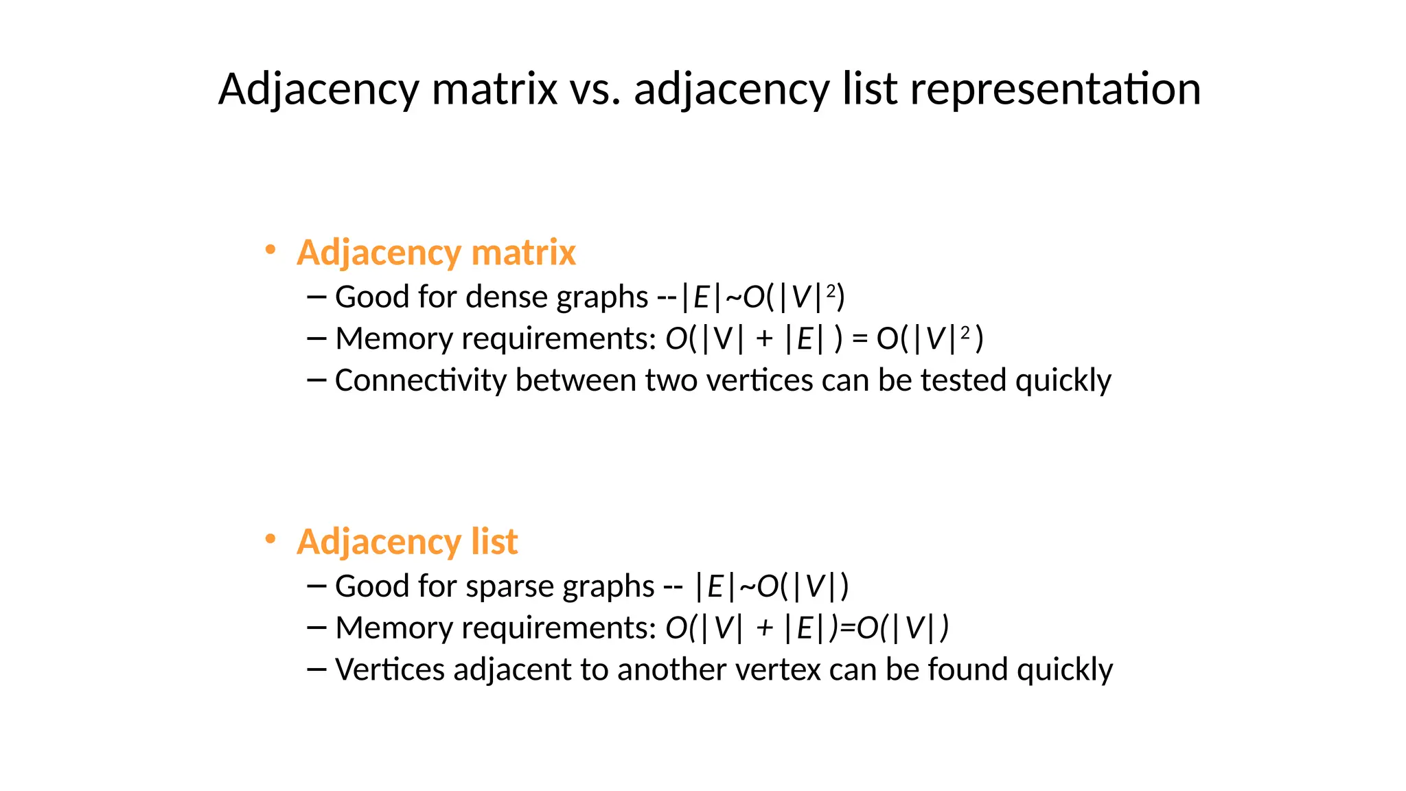
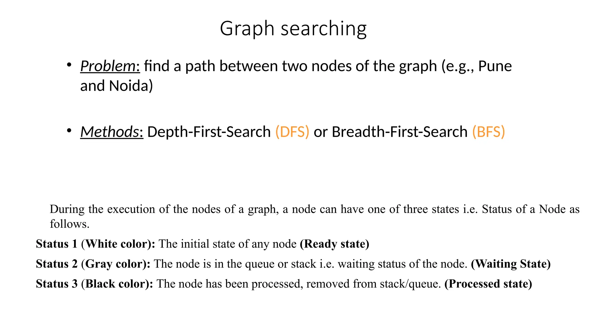
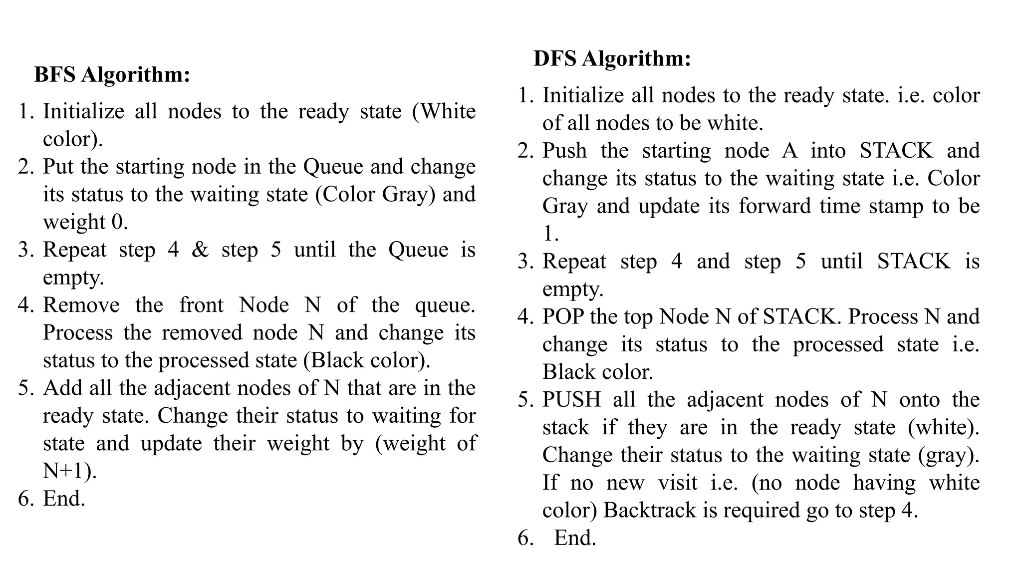
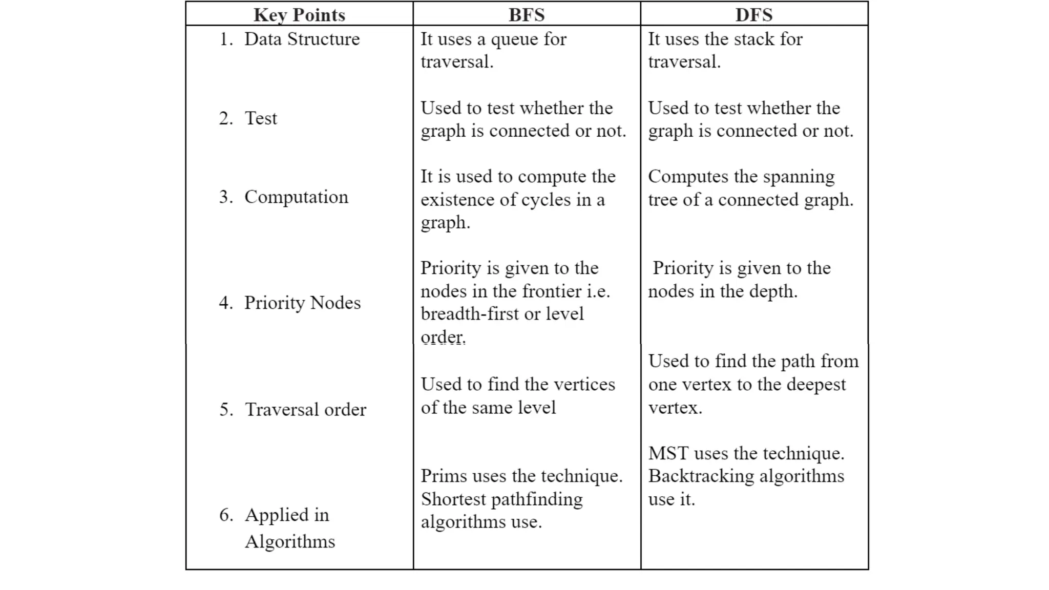
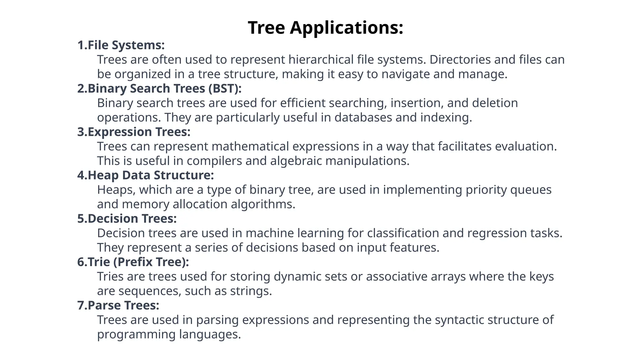
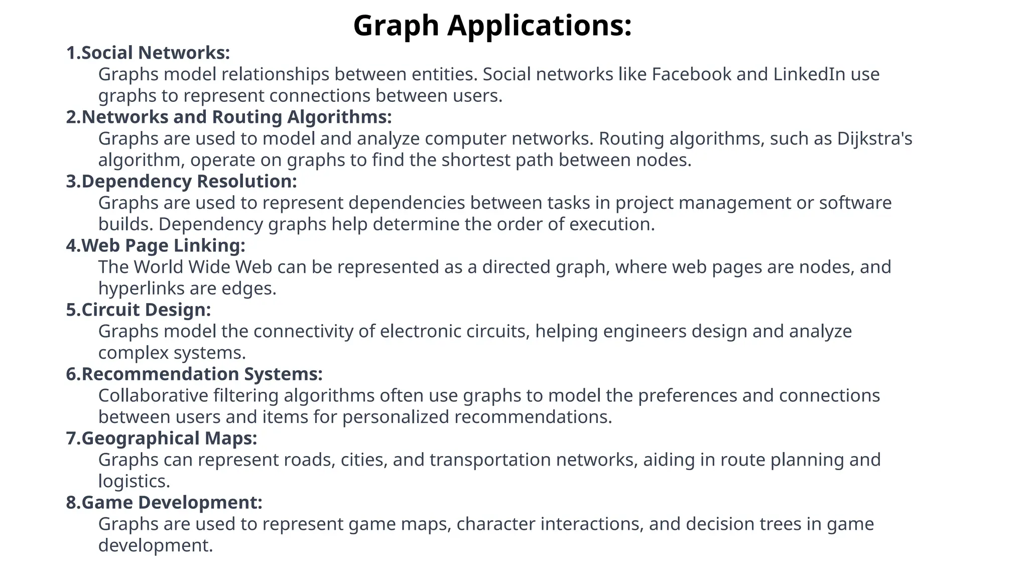
Tree Data Structures
Tree data structures are versatile and powerful ways to organize and
manipulate hierarchical information. In this presentation, we'll
explore their many applications and learn how to use them
effectively.
Definition and Characteristics of Trees
1 Node-Based Structure 🌳
A tree is a collection of nodes connected by
edges, with a single root node and no cycles or
loops.
2 Hierarchical Relationship
Trees represent a natural hierarchical
structure, making them ideal for organizing
data that has parent-child relationships.
3 Multiple Branches 🌱
A tree can have multiple branches, with each
node having at most one parent and zero or
more children.
4 Recursive Nature
The recursive structure of trees allows for
efficient algorithms with logarithmic time
complexity.
Binary Tree
•A tree is a non-linear data structure. It is considered as a powerful and very flexible data
structure that can be used for a wide variety of applications.
Root: Root is the first node of the hierarchical data structure. It is present at the 0th
level and this node represents the base address of the tree. As node A is the root of the
tree.
Nodes: Each data item in the tree is called a node like a node in a graph. It specifies
the information about the data and the links to other items. A, B, C, D, E, and F are the
nodes of the tree.
Degree: The number of nodes connected to a particular node ‘A’ is called the degree of
that node ‘A’. The degree of the leaf node is always one. As deg(A)=2, deg(B)=
deg(C)= deg(D)=3, deg(E)= deg(H)=1,
The degree of the tree is the maximum value of the degree of any node in the
tree. As deg(tree) =3.
Level: The root node of the tree has level 0. The level of any other node is one more
than the level of its parent. As Level(A)=0, Level(B)=Level(C)=1 and so on.
Depth: The maximum level of any leaf is called the depth of the binary tree. As the
depth of the tree would be 3 here.
Height: Height of the tree is the total number of levels from the root
node to the terminal/leaf node. As Height of the tree would be 4 here.
Ancestor: A node “A” is said to be an ancestor of node “B” if A is
either the father of B or the father of some ancestor of B.
For example; A is an ancestor of B, E, etc.
Descendent: A node “B” is said to be a left descendant of node “A” if
B is either the left son of A or the descendant of the left son of A.
For example; G, F, D, B, E are the left descendent to node A.
A node “B” is said to be a right descendant of node “A” if B is
either the right son of A or the descendant of the right son of A.
For example; C, H, I are the right descendent of node A.
Climbing: Is the process of traversing the tree from the leaf node to the
root node, also known as Bottom-up traversal.
Descending: Is the process of traversing the tree from the root node to
the leaf node, also known as Top-down traversal.
TYPES OF BINARY TREES
REPRESENTATION OF BINARY TREE IN MEMORY
TRAVERSING BINARY TREE
Pre-order: N-L-R (node(root)-left-right)
In-order: L-N-R (left-node(root)-right)
Post-order: L-R-N (left-right-node(root))
Operations on Trees
1 Traversing and Searching 🔍
There are multiple ways to traverse
a tree, such as Inorder, Preorder,
Postorder and Level-Order.
Searching can be done recursively or
iteratively, depending on the tree's
structure.
2
Insertion and Deletion ➕ ➖
New nodes can be inserted into a
tree in an ordered manner, while
existing nodes can be deleted using
their position or value. These actions
are crucial for sorting and
manipulating hierarchical data.
Applications of Tree Data Structures
File Systems and
Directory
Structures 📁
Trees are a natural way to
represent the filesystem
hierarchy and the folders
inside it, allowing fast
searches, and efficient
manipulation of files and
directories.
Representing
Hierarchical
Relationships 👩
‍
‍ ‍
‍
‍
‍
‍
‍
‍
‍
‍
‍
‍
‍
‍
👦
‍
‍
‍ ‍
‍
‍
‍
‍
‍
‍
‍
‍
‍
‍
‍
‍
‍
‍
‍
‍
‍
‍
‍
‍
‍
‍
‍
‍
‍
‍
Trees are used to
represent the structure of
an organization, the
hierarchy of a family, or
the relationships between
entities in various
domains.
Sorting and
Searching Algorithms
🕵️
‍
♂️
Popular sorting algorithms
such as Heap sort use trees to
move elements to their final
order, while searching
algorithms like Tries use trees
to efficiently store and
retrieve words or keys.
Advantages and Disadvantages of
Tree Data Structures
Advantages 👍
• Efficient and Fast
• Scalable and Adaptable
• Flexible and Easy to Implement
Disadvantages 👎
• Memory Consumption
• Complexity and Maintenance
• Tree Imbalance and Degeneracy
Efficiency and Complexity Analysis: BST
Average Time
Complexity
Worst-Case Time
Complexity
Space Complexity
Search O(log n) O(n) O(1)
Insert O(log n) O(n) O(n)
Delete O(log n) O(n) O(1)
Graphs
What is a graph?
• A data structure that consists of a set of nodes (vertices) and
a set of edges that relate the nodes to each other
• The set of edges describes relationships among the vertices
A graph G is defined as follows:
G=(V,E)
V(G): a finite, nonempty set of vertices
E(G): a set of edges (pairs of vertices)
• When the edges in a graph have no direction, the
graph is called undirected
Directed vs. undirected graphs
• When the edges in a graph have a direction, the
graph is called directed (or digraph)
E(Graph2) = {(1,3) (3,1) (5,9) (9,11) (5,7) (9,9), (11,1)
Warning: if the graph is
directed, the order of the
vertices in each edge is
important !!
Directed vs. undirected graphs (cont.)
• Trees are special cases of graphs!!
Trees vs graphs
Graph terminology
• Adjacent nodes: two nodes are adjacent if they are
connected by an edge
• Path: a sequence of vertices that connect two nodes
in a graph
• Complete graph: a graph in which every vertex is
directly connected to every other vertex
5 is adjacent to 7
7 is adjacent from 5
• What is the number of edges in a complete
directed graph with N vertices?
N * (N-1)
Graph terminology (cont.)
2
( )
O N
• What is the number of edges in a complete
undirected graph with N vertices?
N * (N-1) / 2
Graph terminology (cont.)
2
( )
O N
• Weighted graph: a graph in which each edge
carries a value
Graph terminology (cont.)
Graph implementation
• Array-based implementation
– A 1D array is used to represent the vertices
– A 2D array (adjacency matrix) is used to represent the
edges
Array-based implementation
Graph implementation (cont.)
• Linked-list implementation
– A 1D array is used to represent the vertices
– A list is used for each vertex v which contains the
vertices which are adjacent from v (adjacency list)
Linked-list implementation
• Adjacency matrix
– Good for dense graphs --|E|~O(|V|2
)
– Memory requirements: O(|V| + |E|) = O(|V|2
)
– Connectivity between two vertices can be tested quickly
• Adjacency list
– Good for sparse graphs -- |E|~O(|V|)
– Memory requirements: O(|V| + |E|)=O(|V|)
– Vertices adjacent to another vertex can be found quickly
Adjacency matrix vs. adjacency list representation
Graph searching
• Problem: find a path between two nodes of the graph (e.g., Pune
and Noida)
• Methods: Depth-First-Search (DFS) or Breadth-First-Search (BFS)
During the execution of the nodes of a graph, a node can have one of three states i.e. Status of a Node as
follows.
Status 1 (White color): The initial state of any node (Ready state)
Status 2 (Gray color): The node is in the queue or stack i.e. waiting status of the node. (Waiting State)
Status 3 (Black color): The node has been processed, removed from stack/queue. (Processed state)
BFS Algorithm:
1. Initialize all nodes to the ready state (White
color).
2. Put the starting node in the Queue and change
its status to the waiting state (Color Gray) and
weight 0.
3. Repeat step 4 & step 5 until the Queue is
empty.
4. Remove the front Node N of the queue.
Process the removed node N and change its
status to the processed state (Black color).
5. Add all the adjacent nodes of N that are in the
ready state. Change their status to waiting for
state and update their weight by (weight of
N+1).
6. End.
DFS Algorithm:
1. Initialize all nodes to the ready state. i.e. color
of all nodes to be white.
2. Push the starting node A into STACK and
change its status to the waiting state i.e. Color
Gray and update its forward time stamp to be
1.
3. Repeat step 4 and step 5 until STACK is
empty.
4. POP the top Node N of STACK. Process N and
change its status to the processed state i.e.
Black color.
5. PUSH all the adjacent nodes of N onto the
stack if they are in the ready state (white).
Change their status to the waiting state (gray).
If no new visit i.e. (no node having white
color) Backtrack is required go to step 4.
6. End.
start end
Tree Applications:
1.File Systems:
Trees are often used to represent hierarchical file systems. Directories and files can
be organized in a tree structure, making it easy to navigate and manage.
2.Binary Search Trees (BST):
Binary search trees are used for efficient searching, insertion, and deletion
operations. They are particularly useful in databases and indexing.
3.Expression Trees:
Trees can represent mathematical expressions in a way that facilitates evaluation.
This is useful in compilers and algebraic manipulations.
4.Heap Data Structure:
Heaps, which are a type of binary tree, are used in implementing priority queues
and memory allocation algorithms.
5.Decision Trees:
Decision trees are used in machine learning for classification and regression tasks.
They represent a series of decisions based on input features.
6.Trie (Prefix Tree):
Tries are trees used for storing dynamic sets or associative arrays where the keys
are sequences, such as strings.
7.Parse Trees:
Trees are used in parsing expressions and representing the syntactic structure of
programming languages.
Graph Applications:
1.Social Networks:
Graphs model relationships between entities. Social networks like Facebook and LinkedIn use
graphs to represent connections between users.
2.Networks and Routing Algorithms:
Graphs are used to model and analyze computer networks. Routing algorithms, such as Dijkstra's
algorithm, operate on graphs to find the shortest path between nodes.
3.Dependency Resolution:
Graphs are used to represent dependencies between tasks in project management or software
builds. Dependency graphs help determine the order of execution.
4.Web Page Linking:
The World Wide Web can be represented as a directed graph, where web pages are nodes, and
hyperlinks are edges.
5.Circuit Design:
Graphs model the connectivity of electronic circuits, helping engineers design and analyze
complex systems.
6.Recommendation Systems:
Collaborative filtering algorithms often use graphs to model the preferences and connections
between users and items for personalized recommendations.
7.Geographical Maps:
Graphs can represent roads, cities, and transportation networks, aiding in route planning and
logistics.
8.Game Development:
Graphs are used to represent game maps, character interactions, and decision trees in game
development.
Conclusion and Key Takeaways
1 Tree Data Structures Are Everywhere
From your computer's file system to your bank's transaction history, trees are
widely used to represent hierarchical data.
2 Choose the Right Tree for the Job
There are many types of trees, each with its own strengths and weaknesses.
Selecting the right one can make a big difference in the efficiency and speed of
your algorithm.
3 Think Recursively
The recursive nature of trees makes them powerful tools for solving complex
problems. By thinking in terms of parent-child relationships, you can unlock the
full potential of tree structure.
Thank you!

D9-Tree and Graph-Data-Structures information.pptx

  • 1.
    Tree Data Structures Treedata structures are versatile and powerful ways to organize and manipulate hierarchical information. In this presentation, we'll explore their many applications and learn how to use them effectively.
  • 2.
    Definition and Characteristicsof Trees 1 Node-Based Structure 🌳 A tree is a collection of nodes connected by edges, with a single root node and no cycles or loops. 2 Hierarchical Relationship Trees represent a natural hierarchical structure, making them ideal for organizing data that has parent-child relationships. 3 Multiple Branches 🌱 A tree can have multiple branches, with each node having at most one parent and zero or more children. 4 Recursive Nature The recursive structure of trees allows for efficient algorithms with logarithmic time complexity.
  • 3.
    Binary Tree •A treeis a non-linear data structure. It is considered as a powerful and very flexible data structure that can be used for a wide variety of applications. Root: Root is the first node of the hierarchical data structure. It is present at the 0th level and this node represents the base address of the tree. As node A is the root of the tree. Nodes: Each data item in the tree is called a node like a node in a graph. It specifies the information about the data and the links to other items. A, B, C, D, E, and F are the nodes of the tree. Degree: The number of nodes connected to a particular node ‘A’ is called the degree of that node ‘A’. The degree of the leaf node is always one. As deg(A)=2, deg(B)= deg(C)= deg(D)=3, deg(E)= deg(H)=1, The degree of the tree is the maximum value of the degree of any node in the tree. As deg(tree) =3. Level: The root node of the tree has level 0. The level of any other node is one more than the level of its parent. As Level(A)=0, Level(B)=Level(C)=1 and so on. Depth: The maximum level of any leaf is called the depth of the binary tree. As the depth of the tree would be 3 here.
  • 4.
    Height: Height ofthe tree is the total number of levels from the root node to the terminal/leaf node. As Height of the tree would be 4 here. Ancestor: A node “A” is said to be an ancestor of node “B” if A is either the father of B or the father of some ancestor of B. For example; A is an ancestor of B, E, etc. Descendent: A node “B” is said to be a left descendant of node “A” if B is either the left son of A or the descendant of the left son of A. For example; G, F, D, B, E are the left descendent to node A. A node “B” is said to be a right descendant of node “A” if B is either the right son of A or the descendant of the right son of A. For example; C, H, I are the right descendent of node A. Climbing: Is the process of traversing the tree from the leaf node to the root node, also known as Bottom-up traversal. Descending: Is the process of traversing the tree from the root node to the leaf node, also known as Top-down traversal.
  • 5.
  • 7.
  • 8.
    TRAVERSING BINARY TREE Pre-order:N-L-R (node(root)-left-right) In-order: L-N-R (left-node(root)-right) Post-order: L-R-N (left-right-node(root))
  • 12.
    Operations on Trees 1Traversing and Searching 🔍 There are multiple ways to traverse a tree, such as Inorder, Preorder, Postorder and Level-Order. Searching can be done recursively or iteratively, depending on the tree's structure. 2 Insertion and Deletion ➕ ➖ New nodes can be inserted into a tree in an ordered manner, while existing nodes can be deleted using their position or value. These actions are crucial for sorting and manipulating hierarchical data.
  • 13.
    Applications of TreeData Structures File Systems and Directory Structures 📁 Trees are a natural way to represent the filesystem hierarchy and the folders inside it, allowing fast searches, and efficient manipulation of files and directories. Representing Hierarchical Relationships 👩 ‍ ‍ ‍ ‍ ‍ ‍ ‍ ‍ ‍ ‍ ‍ ‍ ‍ ‍ ‍ 👦 ‍ ‍ ‍ ‍ ‍ ‍ ‍ ‍ ‍ ‍ ‍ ‍ ‍ ‍ ‍ ‍ ‍ ‍ ‍ ‍ ‍ ‍ ‍ ‍ ‍ ‍ ‍ ‍ ‍ ‍ Trees are used to represent the structure of an organization, the hierarchy of a family, or the relationships between entities in various domains. Sorting and Searching Algorithms 🕵️ ‍ ♂️ Popular sorting algorithms such as Heap sort use trees to move elements to their final order, while searching algorithms like Tries use trees to efficiently store and retrieve words or keys.
  • 14.
    Advantages and Disadvantagesof Tree Data Structures Advantages 👍 • Efficient and Fast • Scalable and Adaptable • Flexible and Easy to Implement Disadvantages 👎 • Memory Consumption • Complexity and Maintenance • Tree Imbalance and Degeneracy
  • 15.
    Efficiency and ComplexityAnalysis: BST Average Time Complexity Worst-Case Time Complexity Space Complexity Search O(log n) O(n) O(1) Insert O(log n) O(n) O(n) Delete O(log n) O(n) O(1)
  • 16.
  • 17.
    What is agraph? • A data structure that consists of a set of nodes (vertices) and a set of edges that relate the nodes to each other • The set of edges describes relationships among the vertices A graph G is defined as follows: G=(V,E) V(G): a finite, nonempty set of vertices E(G): a set of edges (pairs of vertices)
  • 18.
    • When theedges in a graph have no direction, the graph is called undirected Directed vs. undirected graphs
  • 19.
    • When theedges in a graph have a direction, the graph is called directed (or digraph) E(Graph2) = {(1,3) (3,1) (5,9) (9,11) (5,7) (9,9), (11,1) Warning: if the graph is directed, the order of the vertices in each edge is important !! Directed vs. undirected graphs (cont.)
  • 20.
    • Trees arespecial cases of graphs!! Trees vs graphs
  • 21.
    Graph terminology • Adjacentnodes: two nodes are adjacent if they are connected by an edge • Path: a sequence of vertices that connect two nodes in a graph • Complete graph: a graph in which every vertex is directly connected to every other vertex 5 is adjacent to 7 7 is adjacent from 5
  • 22.
    • What isthe number of edges in a complete directed graph with N vertices? N * (N-1) Graph terminology (cont.) 2 ( ) O N
  • 23.
    • What isthe number of edges in a complete undirected graph with N vertices? N * (N-1) / 2 Graph terminology (cont.) 2 ( ) O N
  • 24.
    • Weighted graph:a graph in which each edge carries a value Graph terminology (cont.)
  • 25.
    Graph implementation • Array-basedimplementation – A 1D array is used to represent the vertices – A 2D array (adjacency matrix) is used to represent the edges
  • 26.
  • 27.
    Graph implementation (cont.) •Linked-list implementation – A 1D array is used to represent the vertices – A list is used for each vertex v which contains the vertices which are adjacent from v (adjacency list)
  • 28.
  • 29.
    • Adjacency matrix –Good for dense graphs --|E|~O(|V|2 ) – Memory requirements: O(|V| + |E|) = O(|V|2 ) – Connectivity between two vertices can be tested quickly • Adjacency list – Good for sparse graphs -- |E|~O(|V|) – Memory requirements: O(|V| + |E|)=O(|V|) – Vertices adjacent to another vertex can be found quickly Adjacency matrix vs. adjacency list representation
  • 30.
    Graph searching • Problem:find a path between two nodes of the graph (e.g., Pune and Noida) • Methods: Depth-First-Search (DFS) or Breadth-First-Search (BFS) During the execution of the nodes of a graph, a node can have one of three states i.e. Status of a Node as follows. Status 1 (White color): The initial state of any node (Ready state) Status 2 (Gray color): The node is in the queue or stack i.e. waiting status of the node. (Waiting State) Status 3 (Black color): The node has been processed, removed from stack/queue. (Processed state)
  • 31.
    BFS Algorithm: 1. Initializeall nodes to the ready state (White color). 2. Put the starting node in the Queue and change its status to the waiting state (Color Gray) and weight 0. 3. Repeat step 4 & step 5 until the Queue is empty. 4. Remove the front Node N of the queue. Process the removed node N and change its status to the processed state (Black color). 5. Add all the adjacent nodes of N that are in the ready state. Change their status to waiting for state and update their weight by (weight of N+1). 6. End. DFS Algorithm: 1. Initialize all nodes to the ready state. i.e. color of all nodes to be white. 2. Push the starting node A into STACK and change its status to the waiting state i.e. Color Gray and update its forward time stamp to be 1. 3. Repeat step 4 and step 5 until STACK is empty. 4. POP the top Node N of STACK. Process N and change its status to the processed state i.e. Black color. 5. PUSH all the adjacent nodes of N onto the stack if they are in the ready state (white). Change their status to the waiting state (gray). If no new visit i.e. (no node having white color) Backtrack is required go to step 4. 6. End.
  • 32.
  • 33.
    Tree Applications: 1.File Systems: Treesare often used to represent hierarchical file systems. Directories and files can be organized in a tree structure, making it easy to navigate and manage. 2.Binary Search Trees (BST): Binary search trees are used for efficient searching, insertion, and deletion operations. They are particularly useful in databases and indexing. 3.Expression Trees: Trees can represent mathematical expressions in a way that facilitates evaluation. This is useful in compilers and algebraic manipulations. 4.Heap Data Structure: Heaps, which are a type of binary tree, are used in implementing priority queues and memory allocation algorithms. 5.Decision Trees: Decision trees are used in machine learning for classification and regression tasks. They represent a series of decisions based on input features. 6.Trie (Prefix Tree): Tries are trees used for storing dynamic sets or associative arrays where the keys are sequences, such as strings. 7.Parse Trees: Trees are used in parsing expressions and representing the syntactic structure of programming languages.
  • 34.
    Graph Applications: 1.Social Networks: Graphsmodel relationships between entities. Social networks like Facebook and LinkedIn use graphs to represent connections between users. 2.Networks and Routing Algorithms: Graphs are used to model and analyze computer networks. Routing algorithms, such as Dijkstra's algorithm, operate on graphs to find the shortest path between nodes. 3.Dependency Resolution: Graphs are used to represent dependencies between tasks in project management or software builds. Dependency graphs help determine the order of execution. 4.Web Page Linking: The World Wide Web can be represented as a directed graph, where web pages are nodes, and hyperlinks are edges. 5.Circuit Design: Graphs model the connectivity of electronic circuits, helping engineers design and analyze complex systems. 6.Recommendation Systems: Collaborative filtering algorithms often use graphs to model the preferences and connections between users and items for personalized recommendations. 7.Geographical Maps: Graphs can represent roads, cities, and transportation networks, aiding in route planning and logistics. 8.Game Development: Graphs are used to represent game maps, character interactions, and decision trees in game development.
  • 35.
    Conclusion and KeyTakeaways 1 Tree Data Structures Are Everywhere From your computer's file system to your bank's transaction history, trees are widely used to represent hierarchical data. 2 Choose the Right Tree for the Job There are many types of trees, each with its own strengths and weaknesses. Selecting the right one can make a big difference in the efficiency and speed of your algorithm. 3 Think Recursively The recursive nature of trees makes them powerful tools for solving complex problems. By thinking in terms of parent-child relationships, you can unlock the full potential of tree structure.
  • 36.