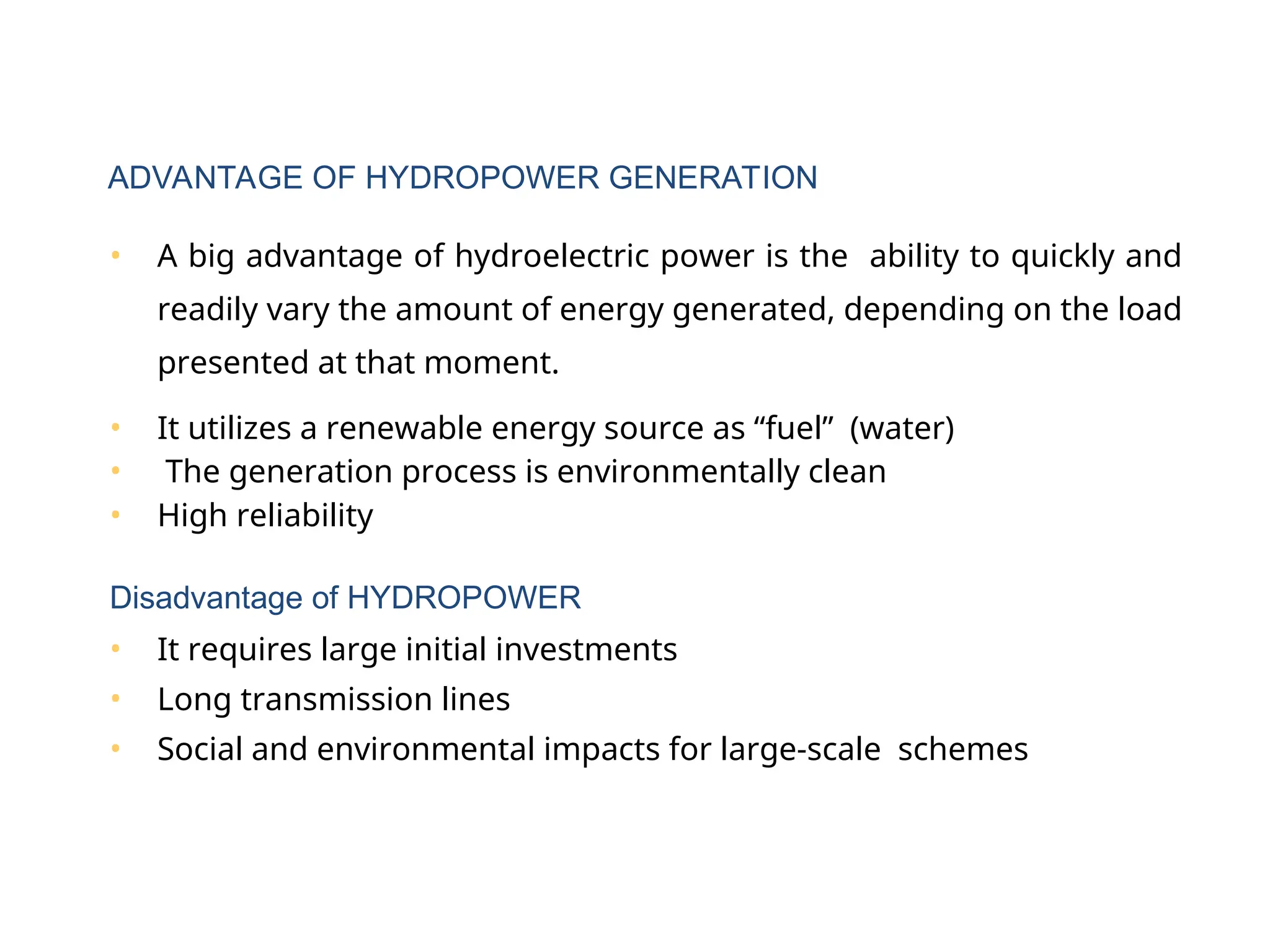
• A bigadvantage of hydroelectric power is the ability to quickly and
readily vary the amount of energy generated, depending on the load
presented at that moment.
• It utilizes a renewable energy source as “fuel” (water)
• The generation process is environmentally clean
• High reliability
Disadvantage of HYDROPOWER
• It requires large initial investments
• Long transmission lines
• Social and environmental impacts for large-scale schemes
ADVANTAGE OF HYDROPOWER GENERATION
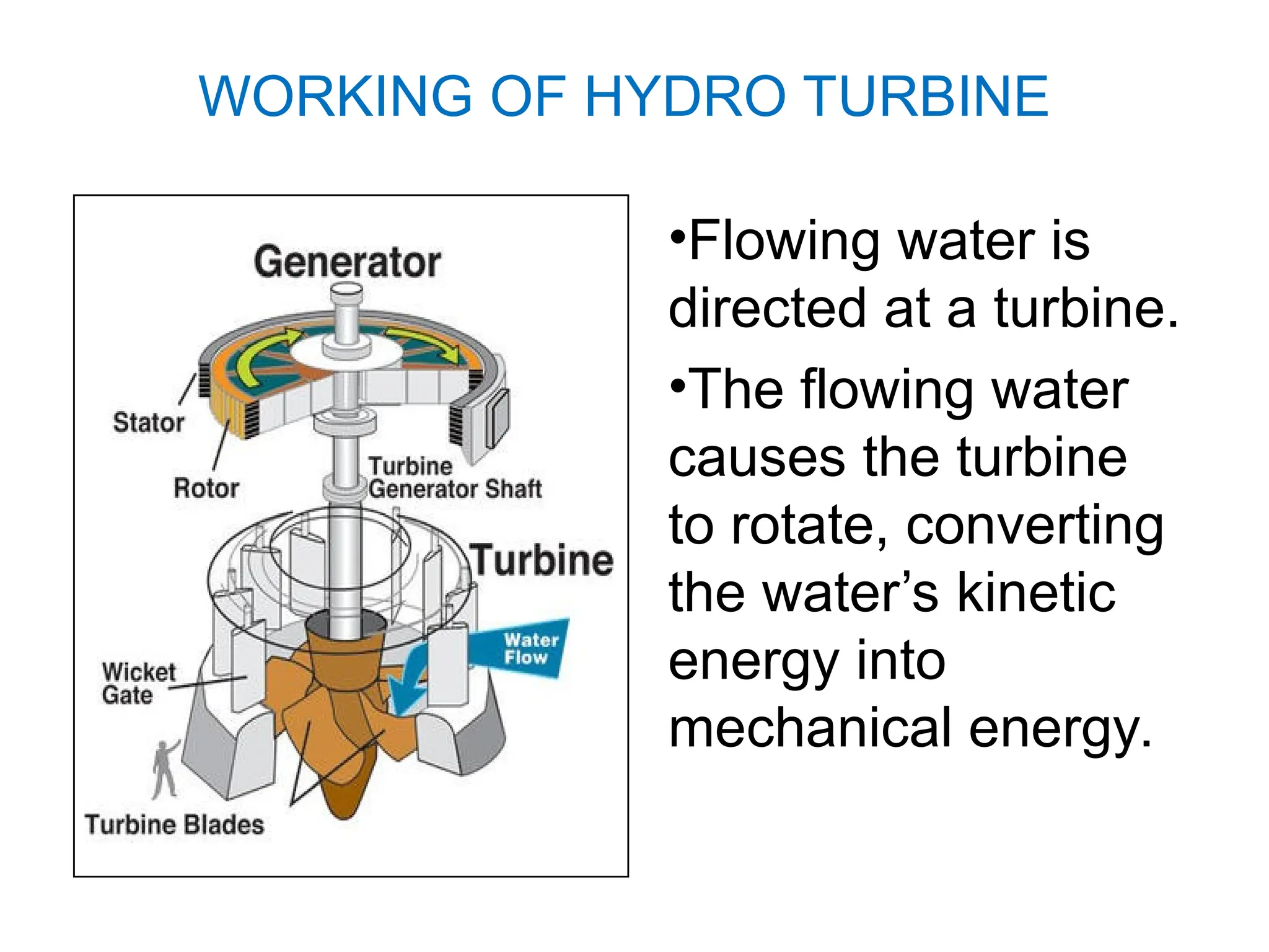
•Flowing water is
directedat a turbine.
•The flowing water
causes the turbine
to rotate, converting
the water’s kinetic
energy into
mechanical energy.
WORKING OF HYDRO TURBINE
6.
• The mechanicalenergy produced by the
turbine is converted into electric energy
using a turbine generator.
• Inside the generator, the shaft of the
turbine spins a magnet inside coils of
copper wire.
• It is a fact of nature that moving a magnet
near a conductor causes an electric
current.
7.
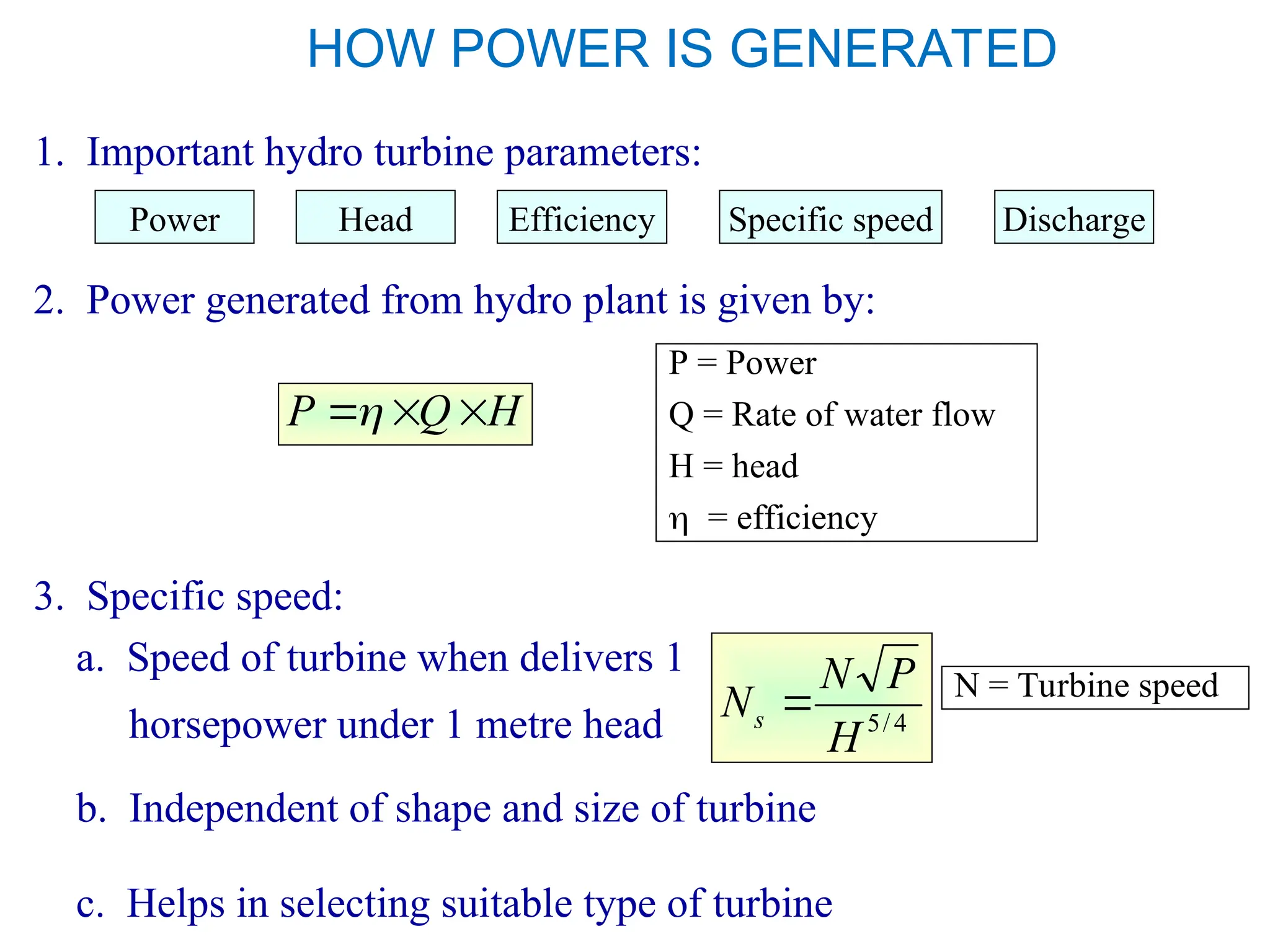
HOW POWER ISGENERATED
1. Important hydro turbine parameters:
2. Power generated from hydro plant is given by:
H
Q
P
P = Power
Q = Rate of water flow
H = head
= efficiency
3. Specific speed:
a. Speed of turbine when delivers 1
horsepower under 1 metre head
Power Head Efficiency Specific speed Discharge
b. Independent of shape and size of turbine
c. Helps in selecting suitable type of turbine
4
/
5
H
P
N
Ns N = Turbine speed
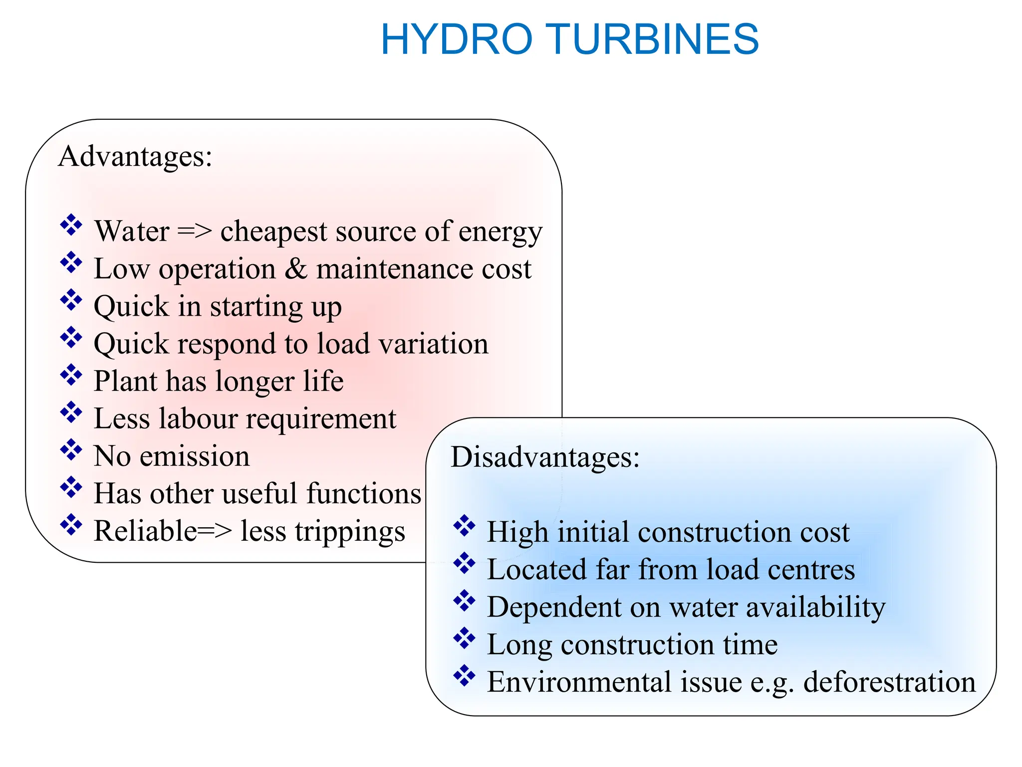
HYDRO TURBINES
Advantages:
Water=> cheapest source of energy
Low operation & maintenance cost
Quick in starting up
Quick respond to load variation
Plant has longer life
Less labour requirement
No emission
Has other useful functions
Reliable=> less trippings
Disadvantages:
High initial construction cost
Located far from load centres
Dependent on water availability
Long construction time
Environmental issue e.g. deforestration
10.
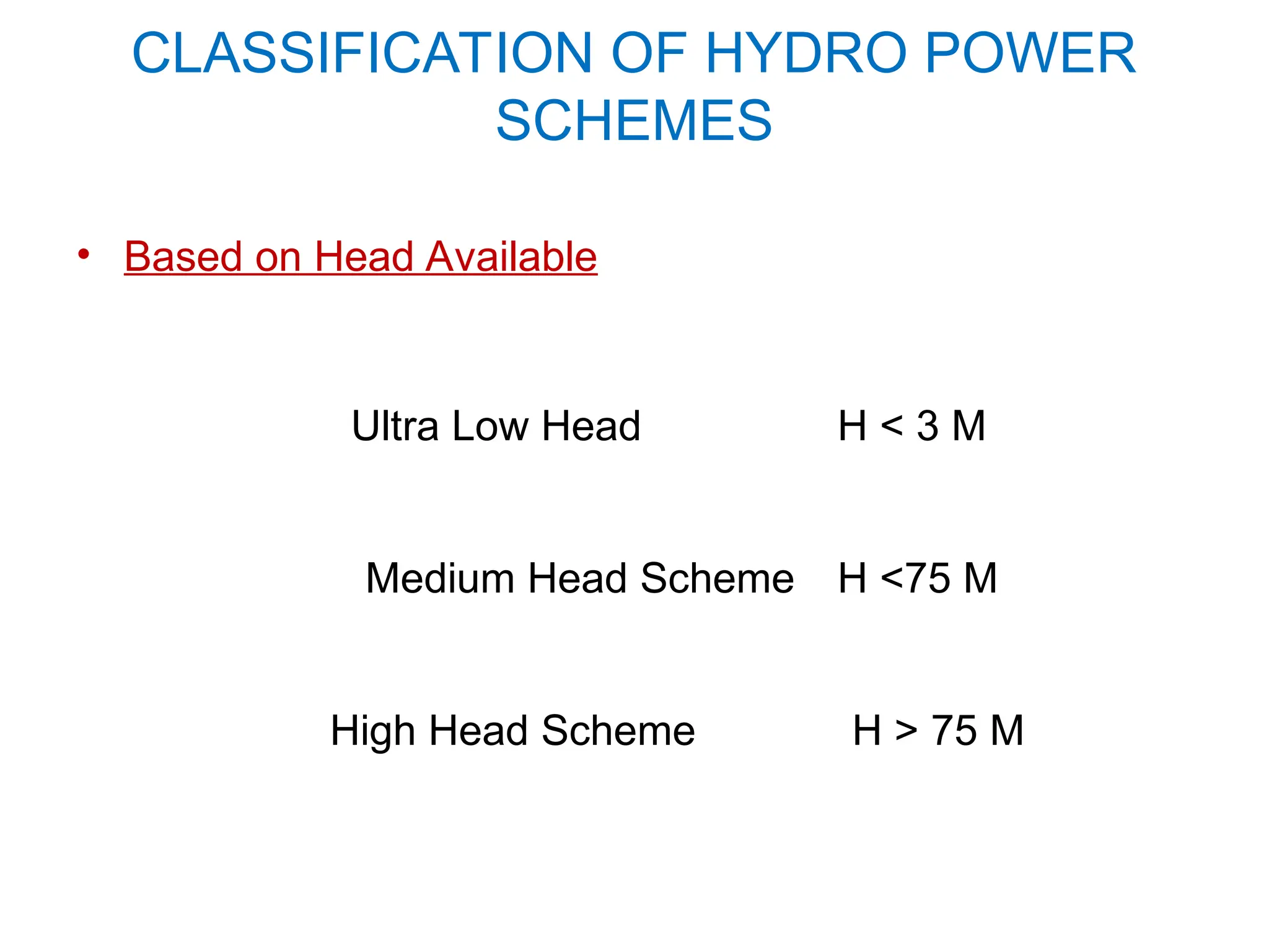
CLASSIFICATION OF HYDROPOWER
SCHEMES
• Based on Head Available
Ultra Low Head H < 3 M
Medium Head Scheme H <75 M
High Head Scheme H > 75 M
11.
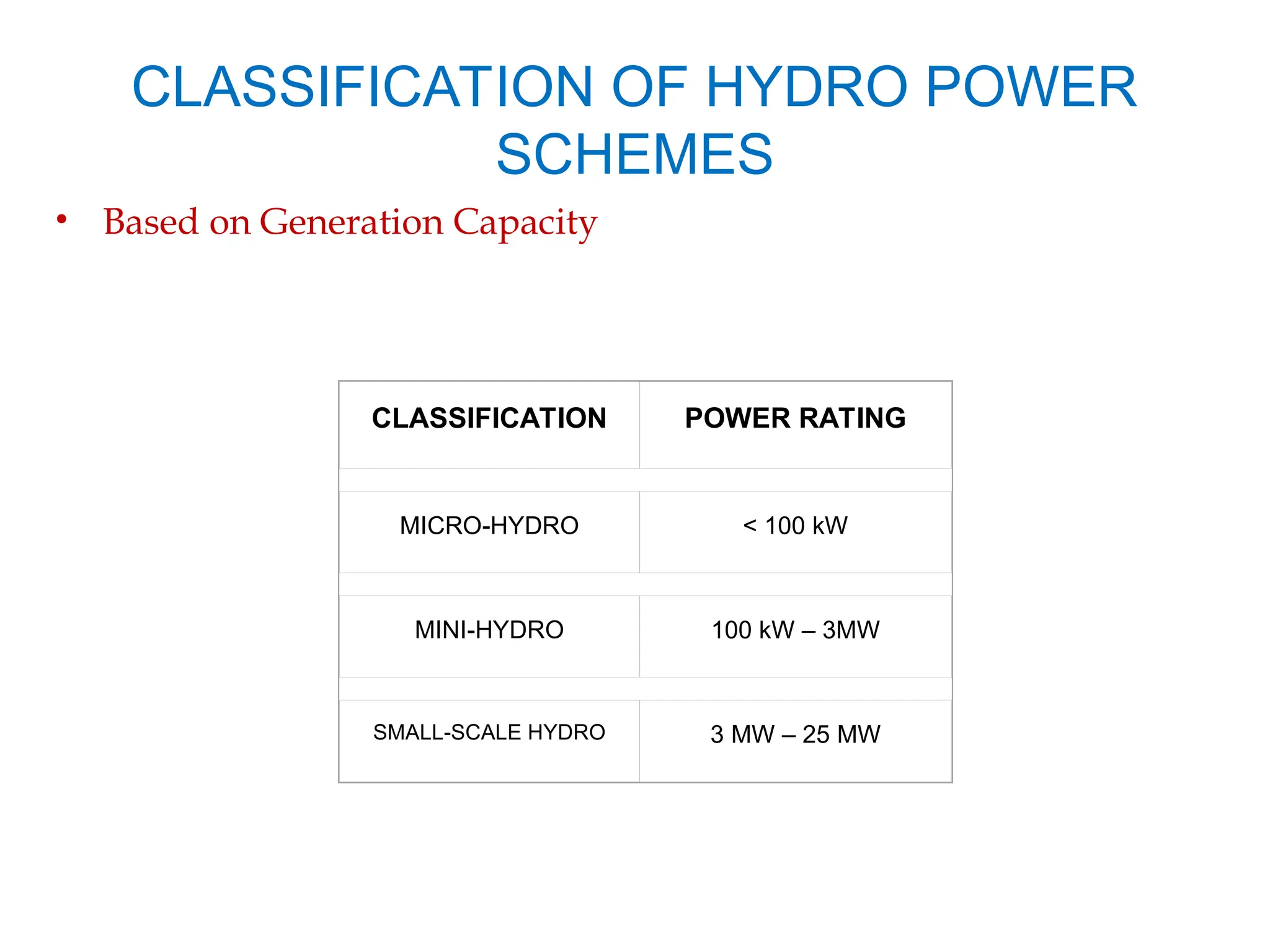
CLASSIFICATION OF HYDROPOWER
SCHEMES
• Based on Generation Capacity
CLASSIFICATION POWER RATING
MICRO-HYDRO < 100 kW
MINI-HYDRO 100 kW – 3MW
SMALL-SCALE HYDRO 3 MW – 25 MW
12.
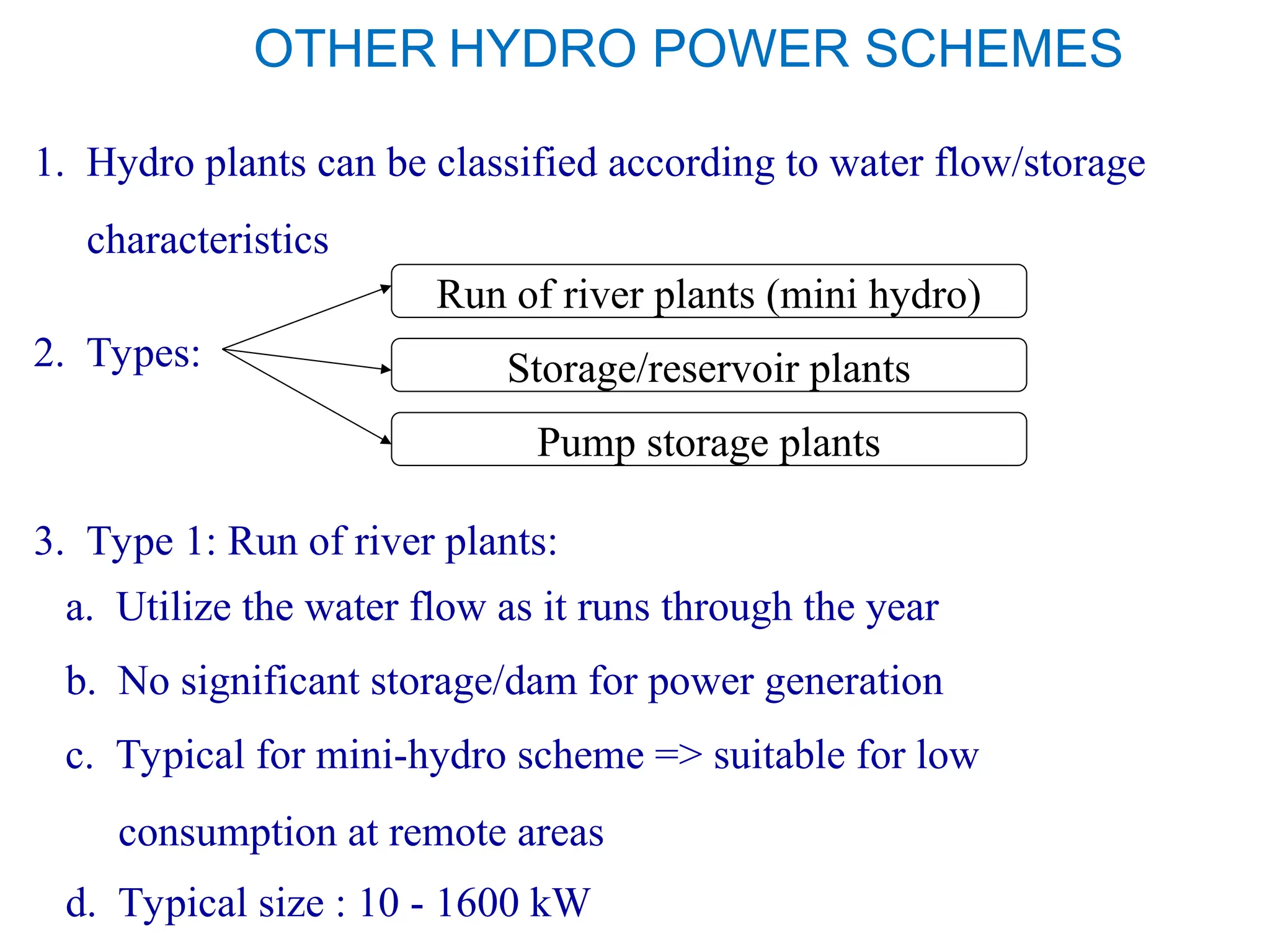
OTHER HYDRO POWERSCHEMES
1. Hydro plants can be classified according to water flow/storage
characteristics
2. Types:
Run of river plants (mini hydro)
Storage/reservoir plants
Pump storage plants
3. Type 1: Run of river plants:
a. Utilize the water flow as it runs through the year
b. No significant storage/dam for power generation
c. Typical for mini-hydro scheme => suitable for low
consumption at remote areas
d. Typical size : 10 - 1600 kW
13.
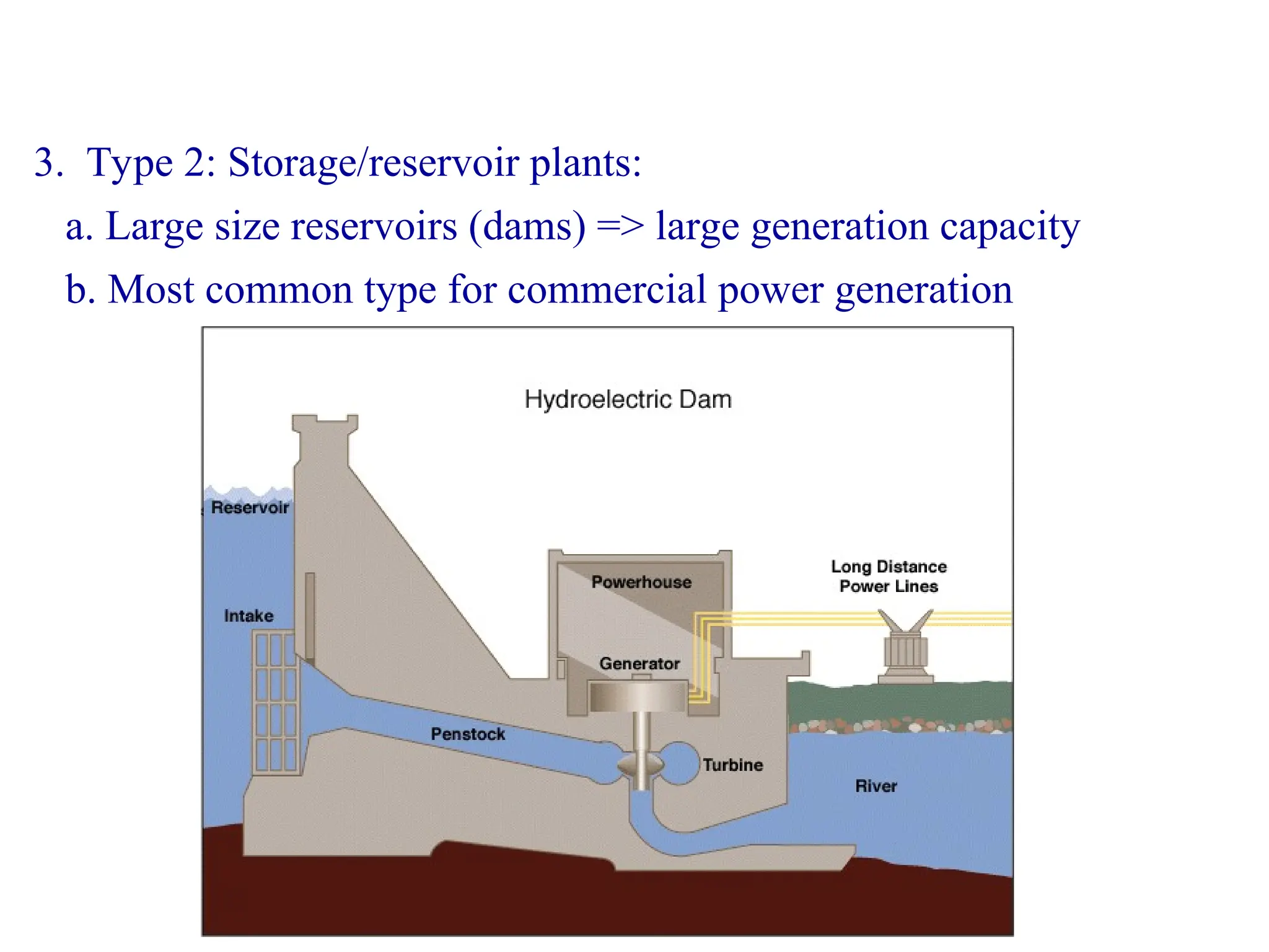
3. Type 2:Storage/reservoir plants:
a. Large size reservoirs (dams) => large generation capacity
b. Most common type for commercial power generation
14.
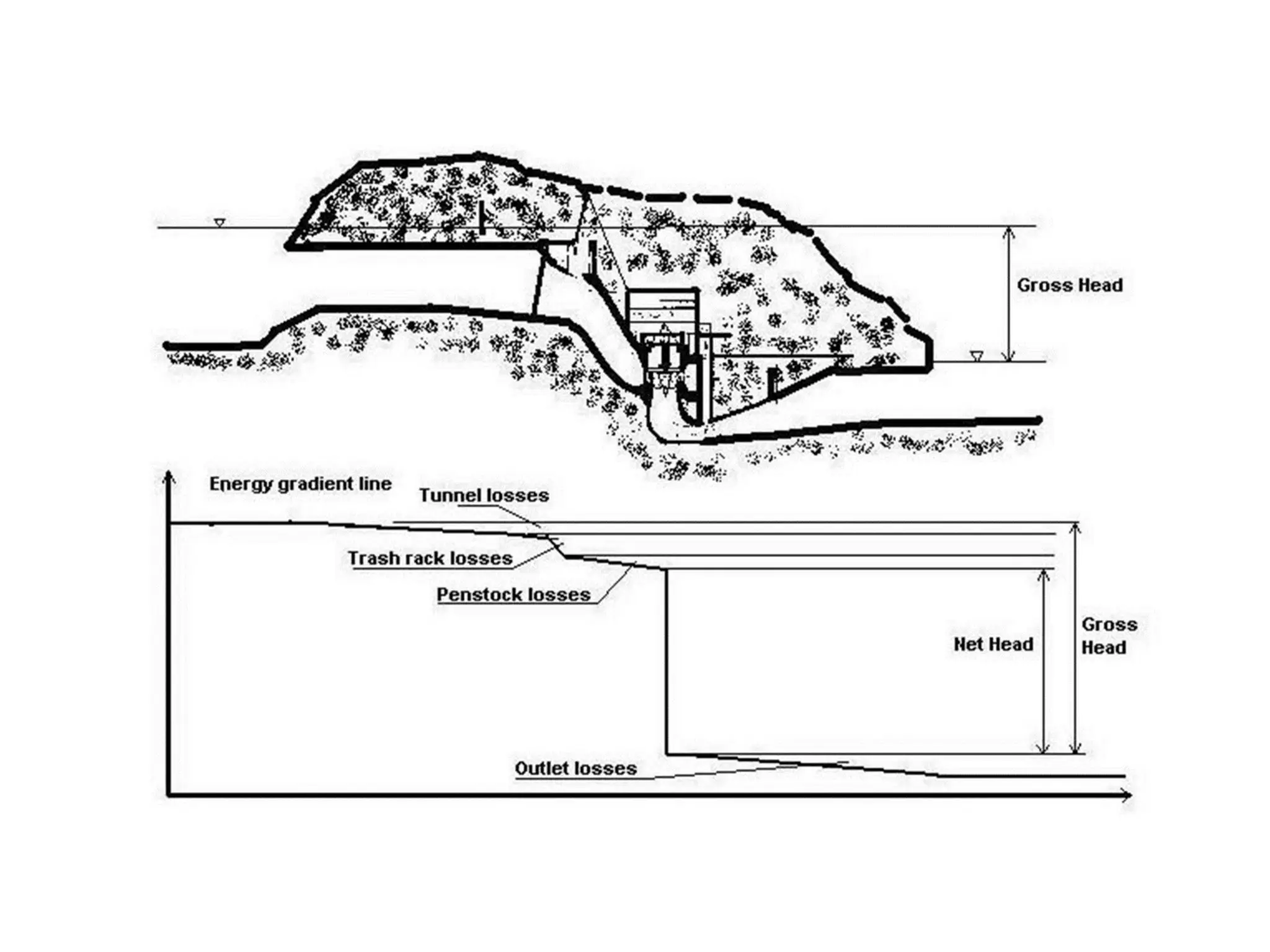
• GROSS HEADof a hydropower facility is the
difference between headwater elevation and
tailwater elevation.
• NET HEAD is the effective head on the turbine
and is equal to the gross head minus the
hydraulic losses before entrance to the turbine
and outlet losses
Hydraulic Head
16.
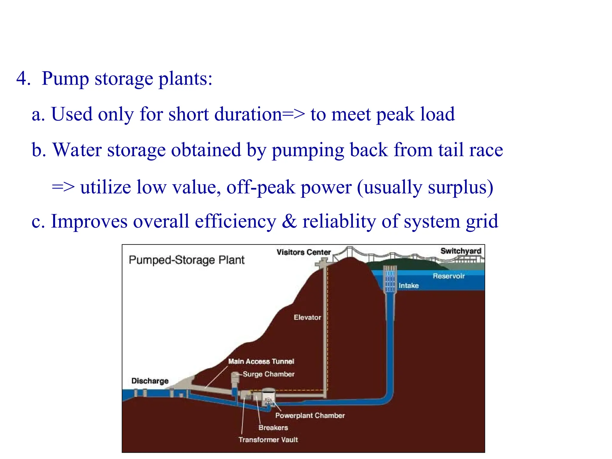
4. Pump storageplants:
b. Water storage obtained by pumping back from tail race
=> utilize low value, off-peak power (usually surplus)
a. Used only for short duration=> to meet peak load
c. Improves overall efficiency & reliablity of system grid
17.
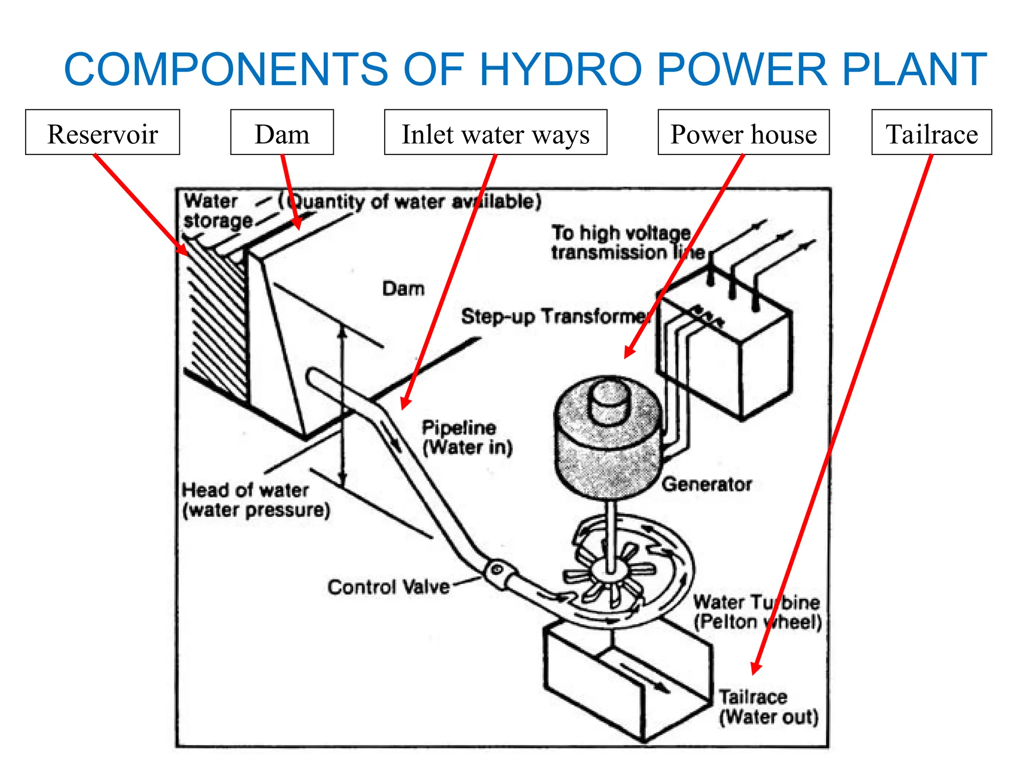
Reservoir Dam Inletwater ways Power house Tailrace
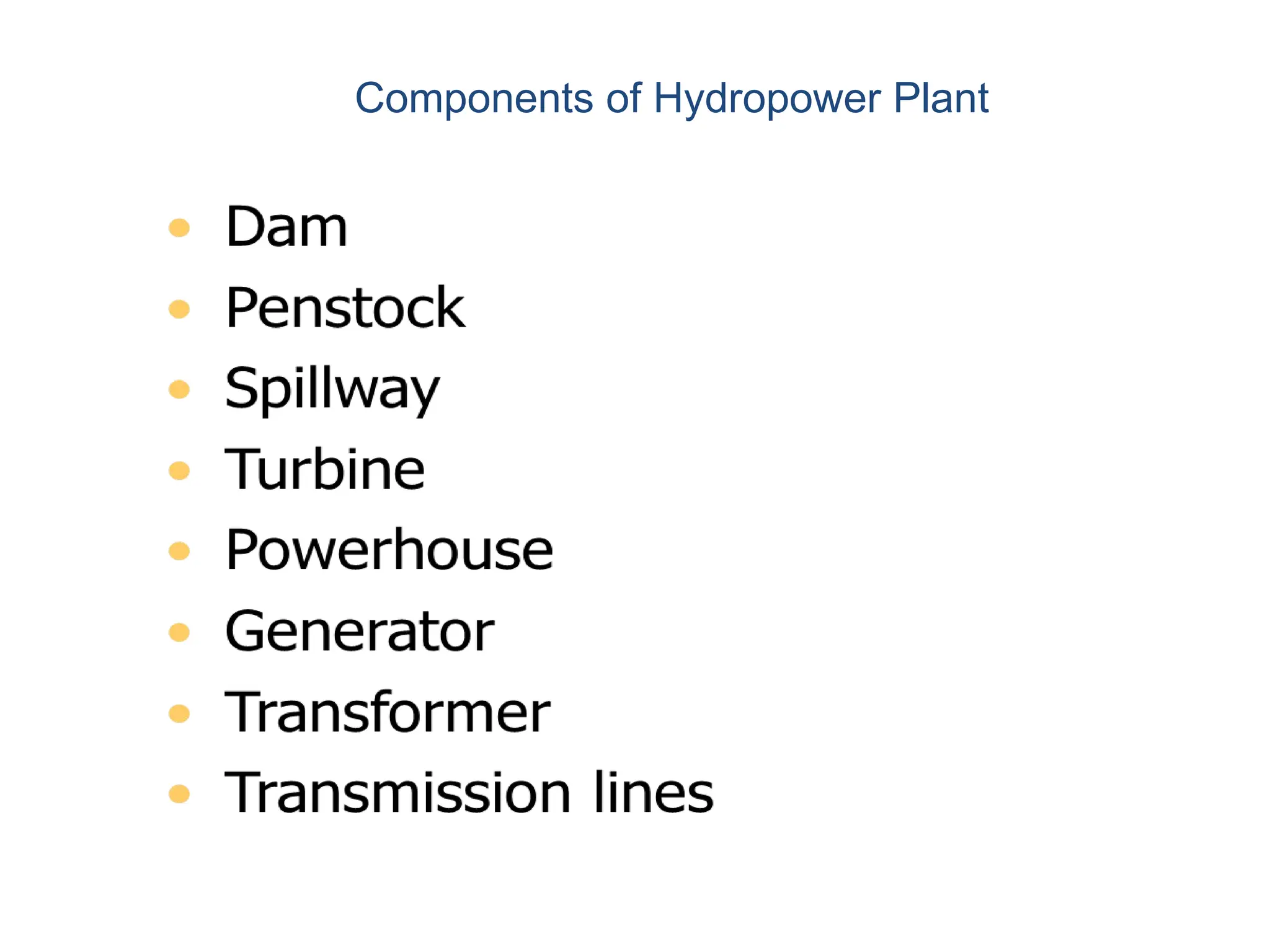
COMPONENTS OF HYDRO POWER PLANT
18.
MAJOR COMPONENTS
1. Reservoir:
a.Includes catchment area and water reservoir
c. Head race => water surface level of the reservoir
d. Reservoir can be natural or artificial (i.e. with dam)
b. Purpose: to store water
2. Dam:
a. A structure of masonry and/or rock fill built across a river
b. Purpose: i) to provide head of water
ii) to create storage or pondage
19.
MAJOR COMPONENTS
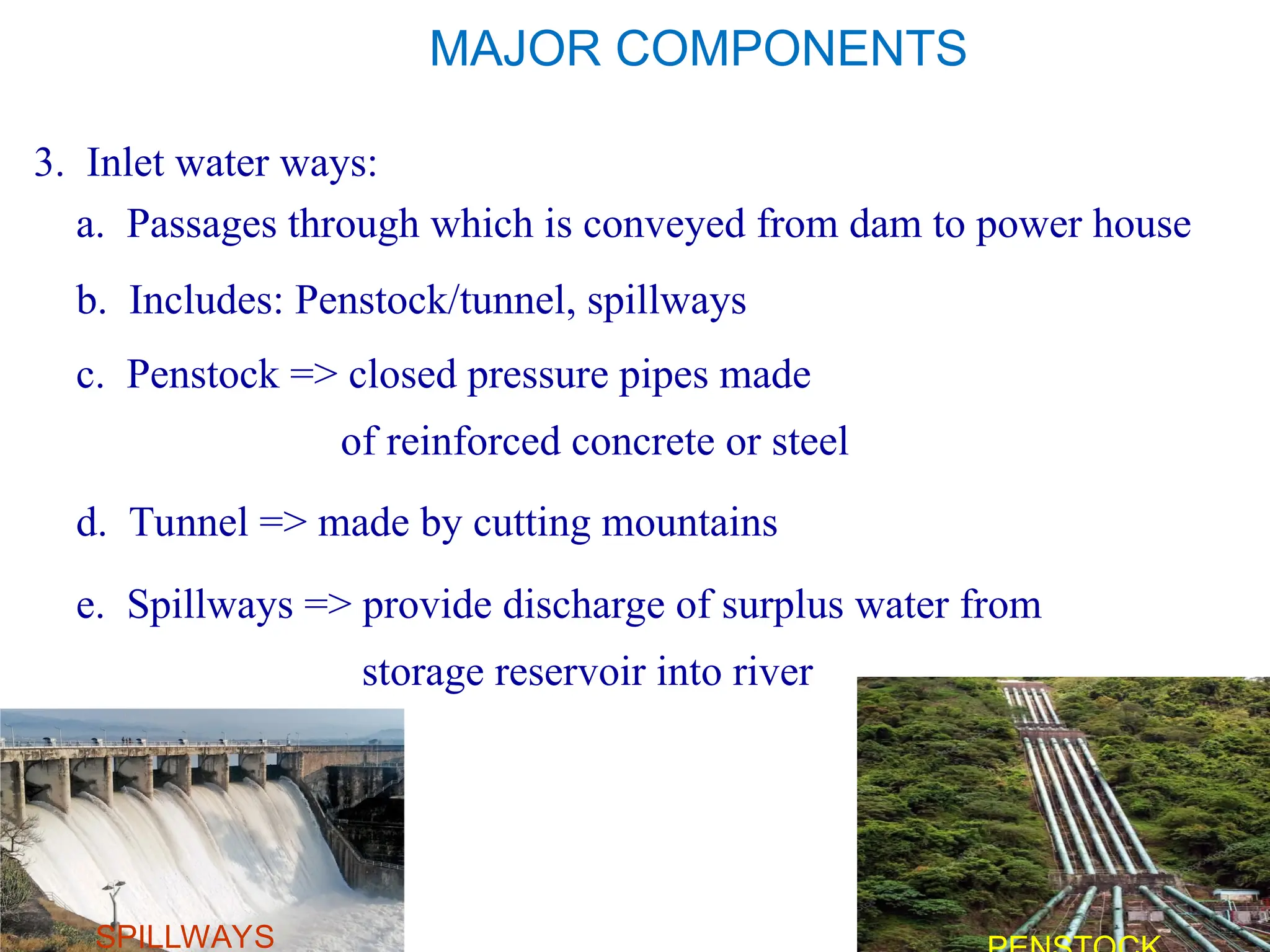
3. Inletwater ways:
a. Passages through which is conveyed from dam to power house
c. Penstock => closed pressure pipes made
of reinforced concrete or steel
b. Includes: Penstock/tunnel, spillways
d. Tunnel => made by cutting mountains
e. Spillways => provide discharge of surplus water from
storage reservoir into river
SPILLWAYS
20.
MAJOR COMPONENTS
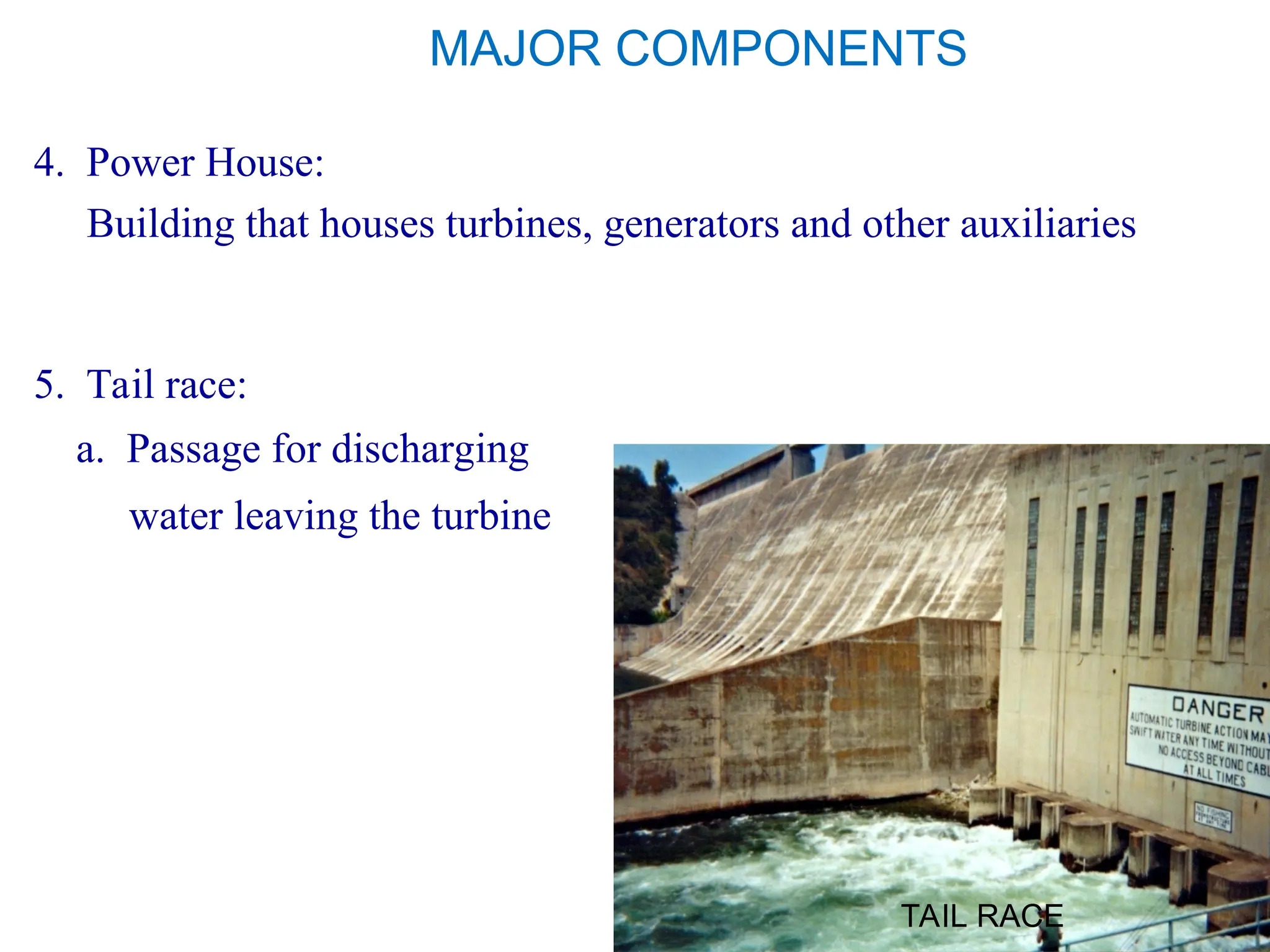
4. PowerHouse:
Building that houses turbines, generators and other auxiliaries
5. Tail race:
a. Passage for discharging
water leaving the turbine
TAIL RACE
21.
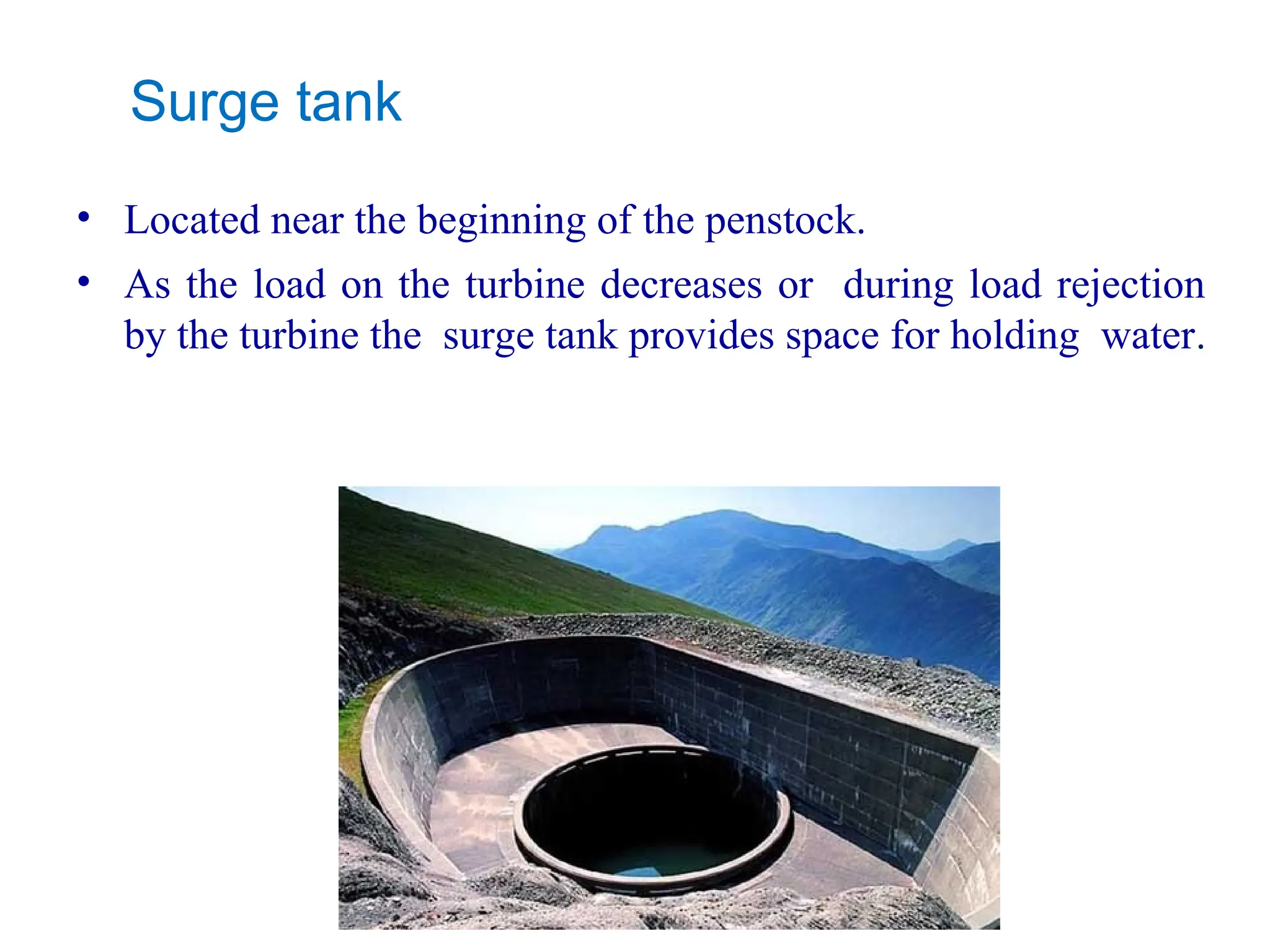
Surge tank
• Locatednear the beginning of the penstock.
• As the load on the turbine decreases or during load rejection
by the turbine the surge tank provides space for holding water.
22.
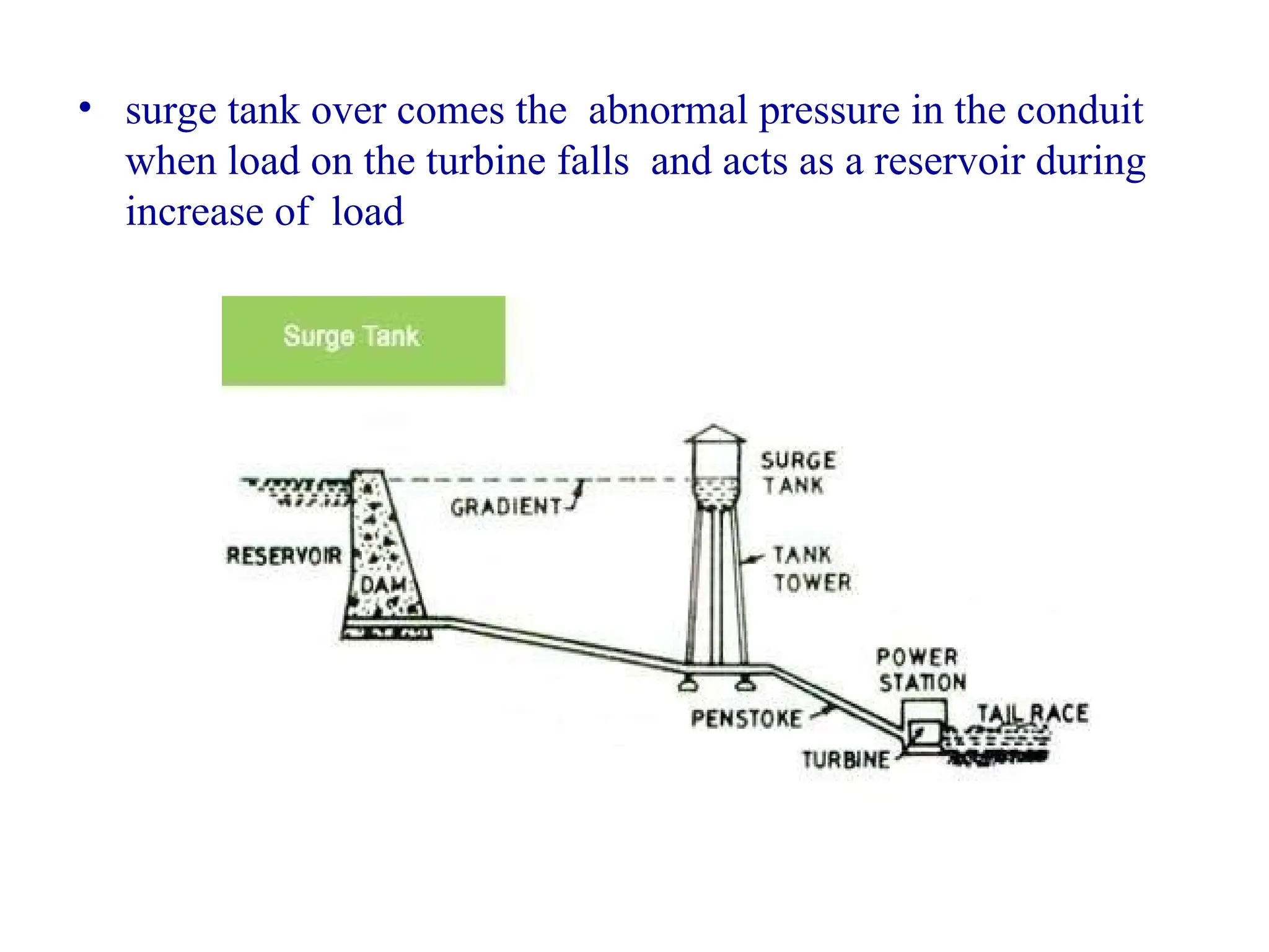
• surge tankover comes the abnormal pressure in the conduit
when load on the turbine falls and acts as a reservoir during
increase of load
he
turbine.
23.
TURBINES
• turbines areused to convert the energy water of falling water
into mechanical energy.
• water turbine is a rotary engine that takes energy from
moving water.
• flowing water is directed on to the blades of a turbine runner,
creating a force on the blades
24.
• Since therunner is spinning, the force acts through a distance
n this way, energy is transferred from the water flow to the
turbine.
• The principal types of turbines are:
1) Impulse turbine
2) Reaction Turbine
25.
25
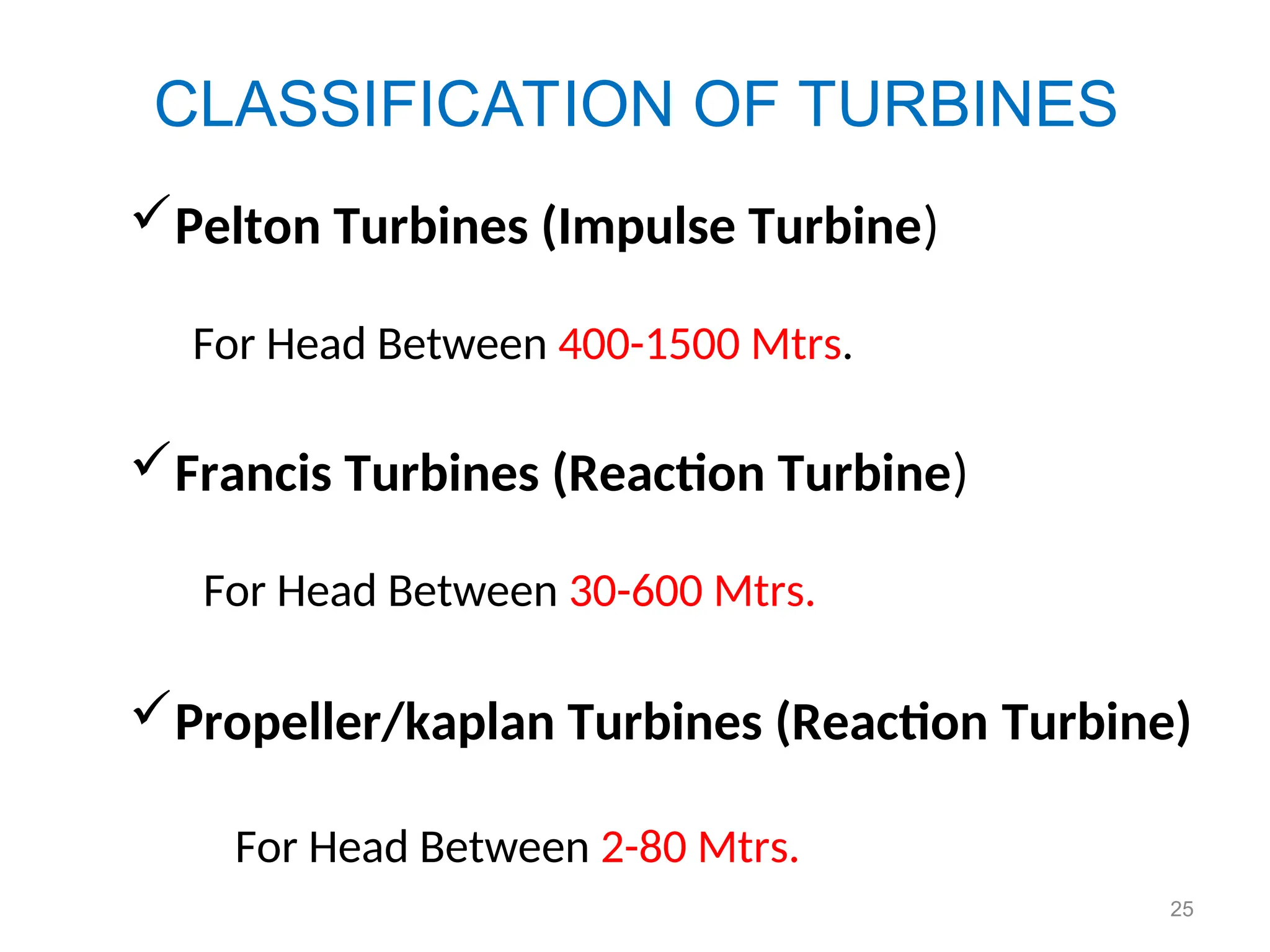
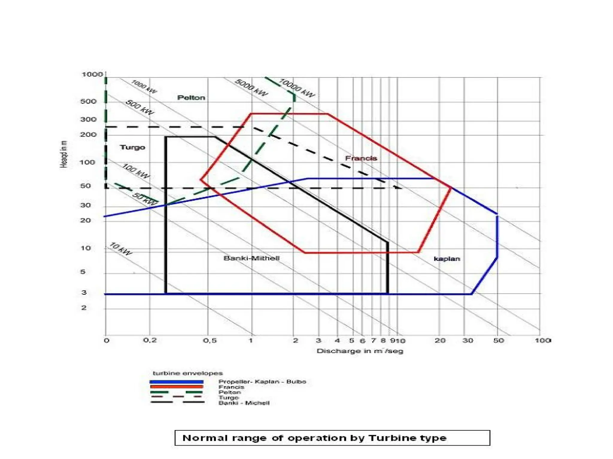
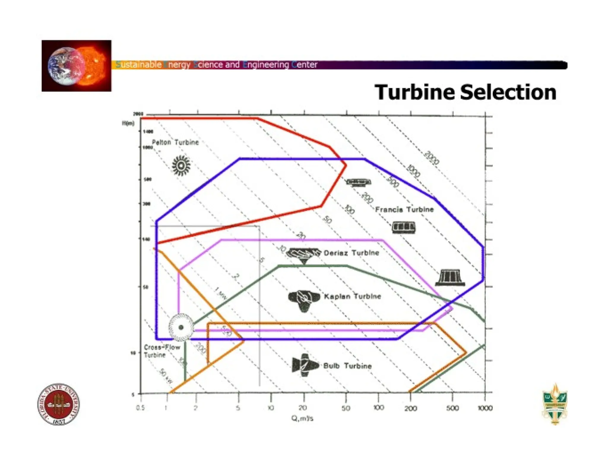
CLASSIFICATION OF TURBINES
PeltonTurbines (Impulse Turbine)
For Head Between 400-1500 Mtrs.
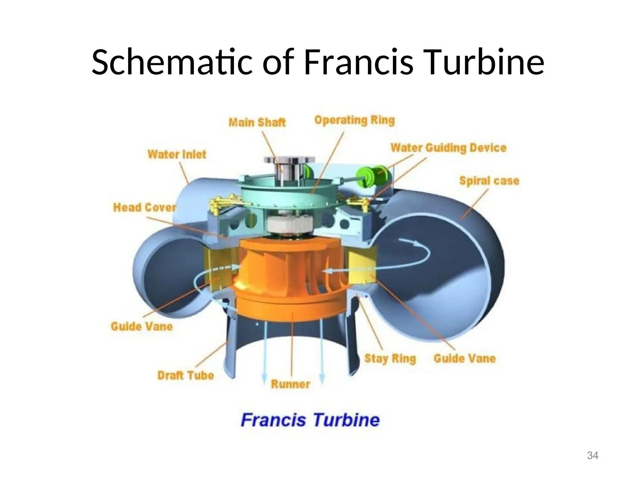
Francis Turbines (Reaction Turbine)
For Head Between 30-600 Mtrs.
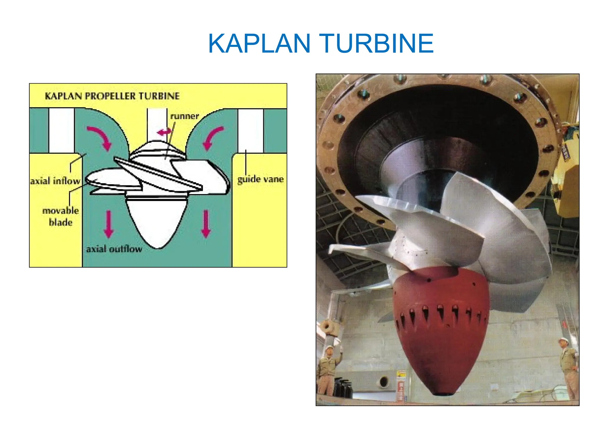
Propeller/kaplan Turbines (Reaction Turbine)
For Head Between 2-80 Mtrs.
26.
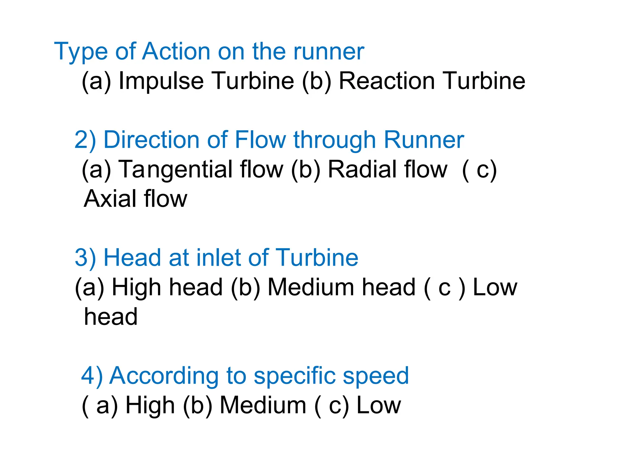
Type of Actionon the runner
(a) Impulse Turbine (b) Reaction Turbine
2) Direction of Flow through Runner
(a) Tangential flow (b) Radial flow ( c)
Axial flow
3) Head at inlet of Turbine
(a) High head (b) Medium head ( c ) Low
head
4) According to specific speed
( a) High (b) Medium ( c) Low
27.
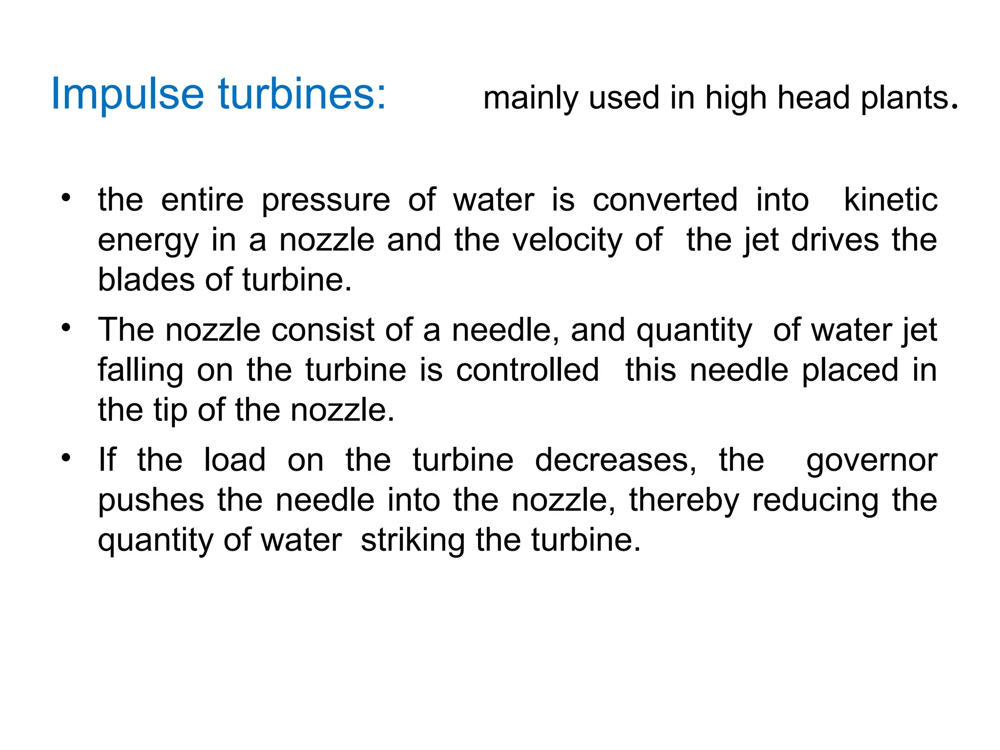
Impulse turbines: mainlyused in high head plants.
• the entire pressure of water is converted into kinetic
energy in a nozzle and the velocity of the jet drives the
blades of turbine.
• The nozzle consist of a needle, and quantity of water jet
falling on the turbine is controlled this needle placed in
the tip of the nozzle.
• If the load on the turbine decreases, the governor
pushes the needle into the nozzle, thereby reducing the
quantity of water striking the turbine.
28.
Examples of Impulseturbines are:
• Pelton Wheel.
• Turgo
• Michell-Banki (also known as the Cross
flow or Ossberger turbine.
Reaction turbines :are mainly for low and medium
head plants.
• In reaction turbine the water enters the runner
partly with pressure energy and partly with
velocity head.
• Most water turbines in use are reaction turbines
and are used in low (<30m/98 ft) and medium
(30-300m/98–984 ft)head applications.
• In reaction turbine pressure drop occurs in both
fixed and moving blades.
40
Comparison of Impulse& Reaction Turbines
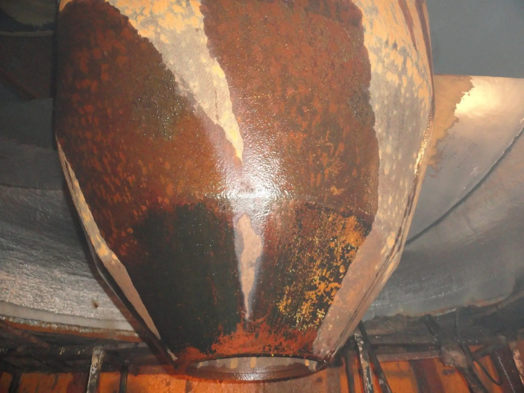
Experience has shown that under given conditions, wear
will be more in reaction turbines i.e. Propeller, Kaplan and
Francis. This is because water enters under pressure and
the under water components experience a severe erosive
action of water on the metal.
In case of pelton wheels, water hits the buckets and
because of this impact, buckets wear out but this may not
be much as compared to the reaction turbines, where the
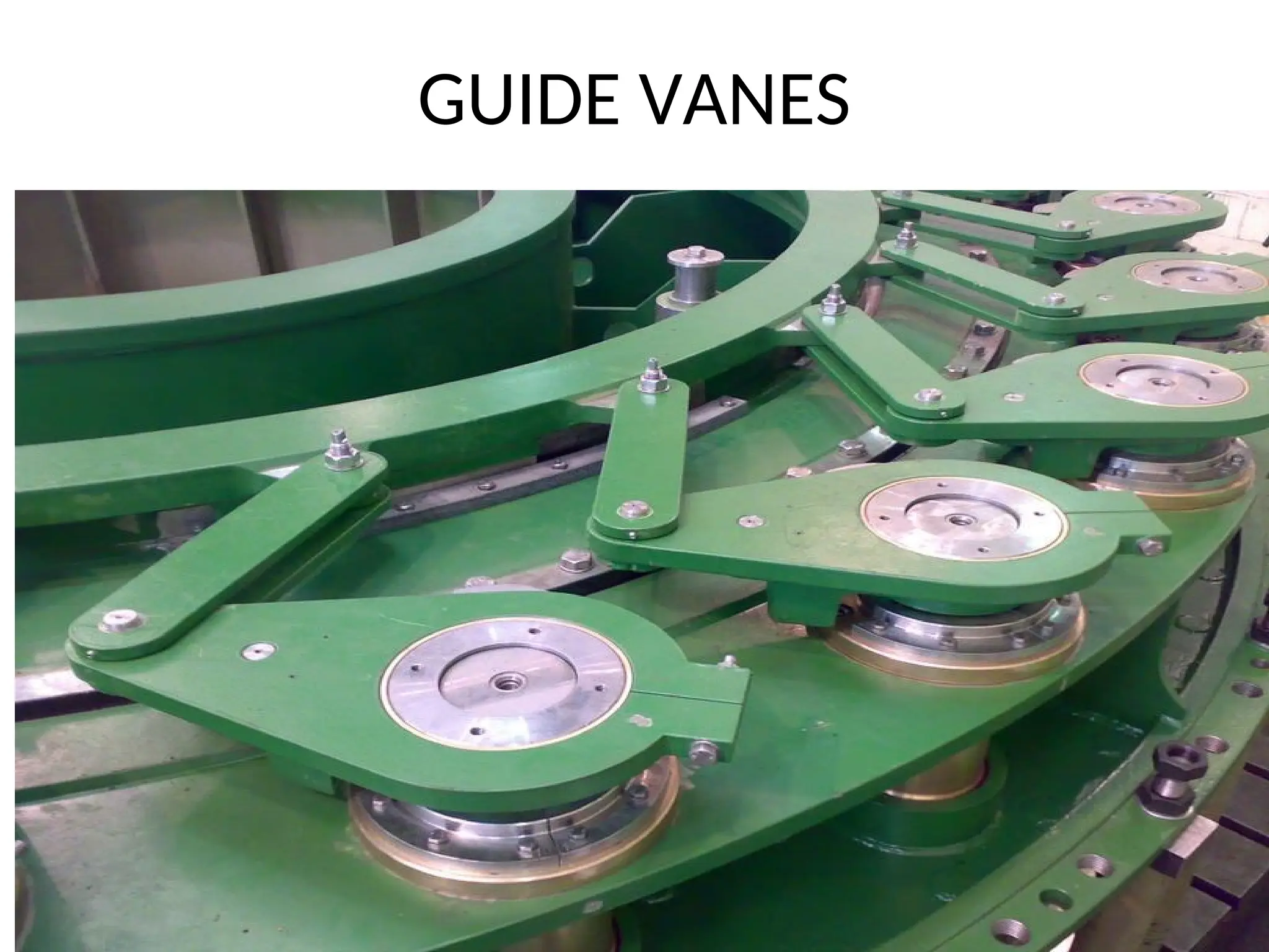
water is made to enter through constrained paths like
vanes and gates.
43.
43
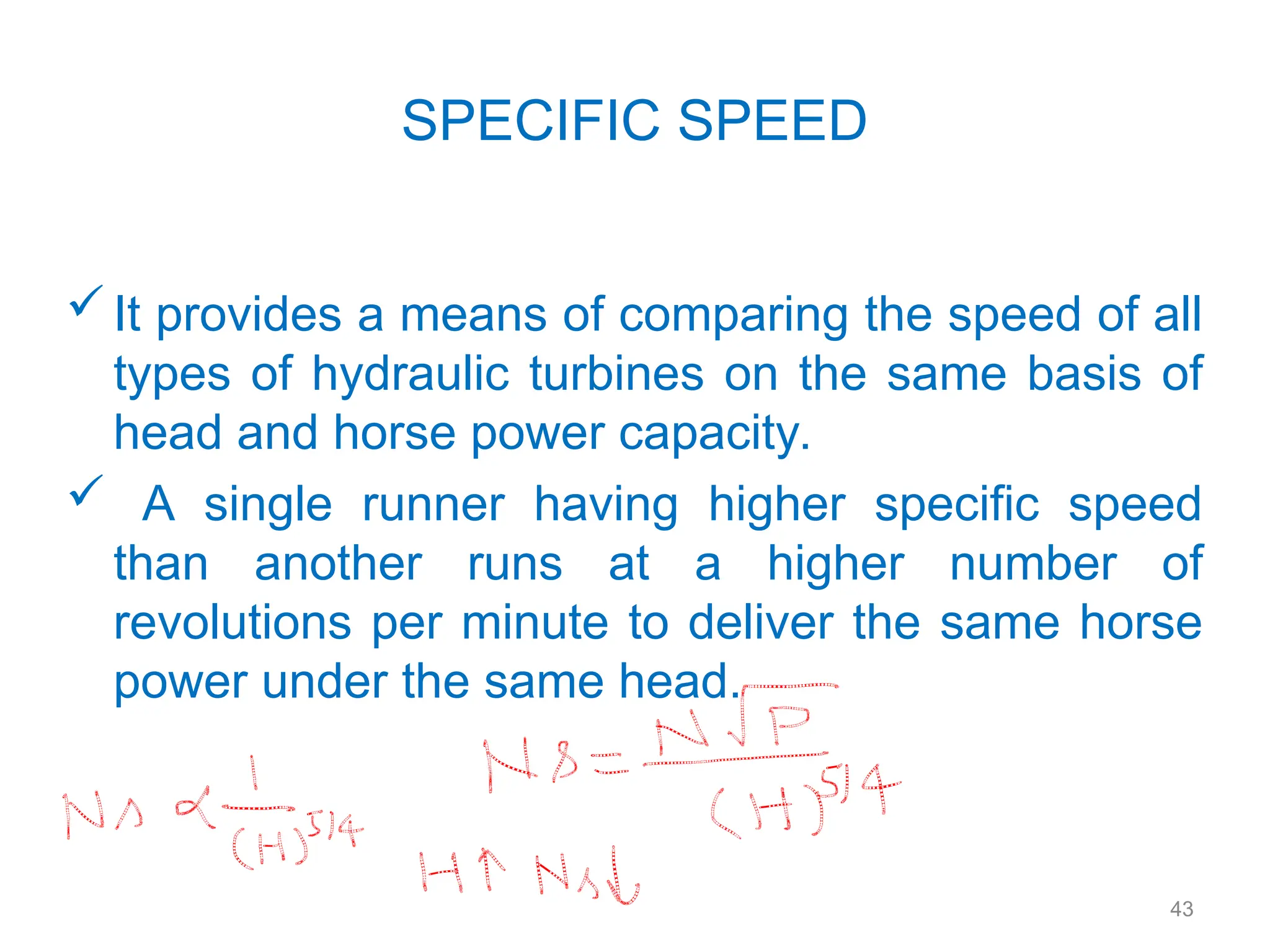
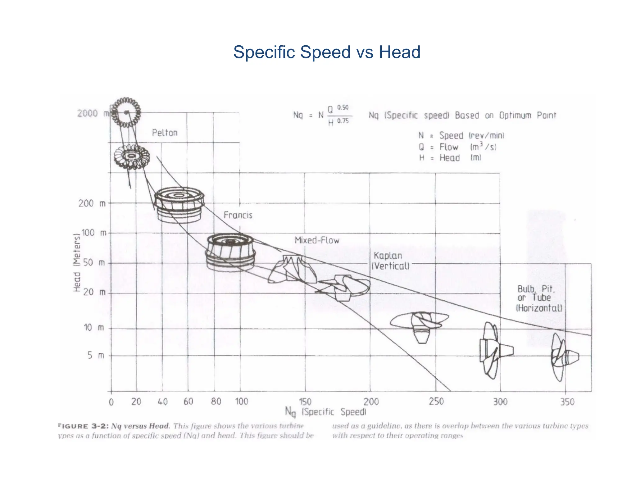
SPECIFIC SPEED
It providesa means of comparing the speed of all
types of hydraulic turbines on the same basis of
head and horse power capacity.
A single runner having higher specific speed
than another runs at a higher number of
revolutions per minute to deliver the same horse
power under the same head.
44.
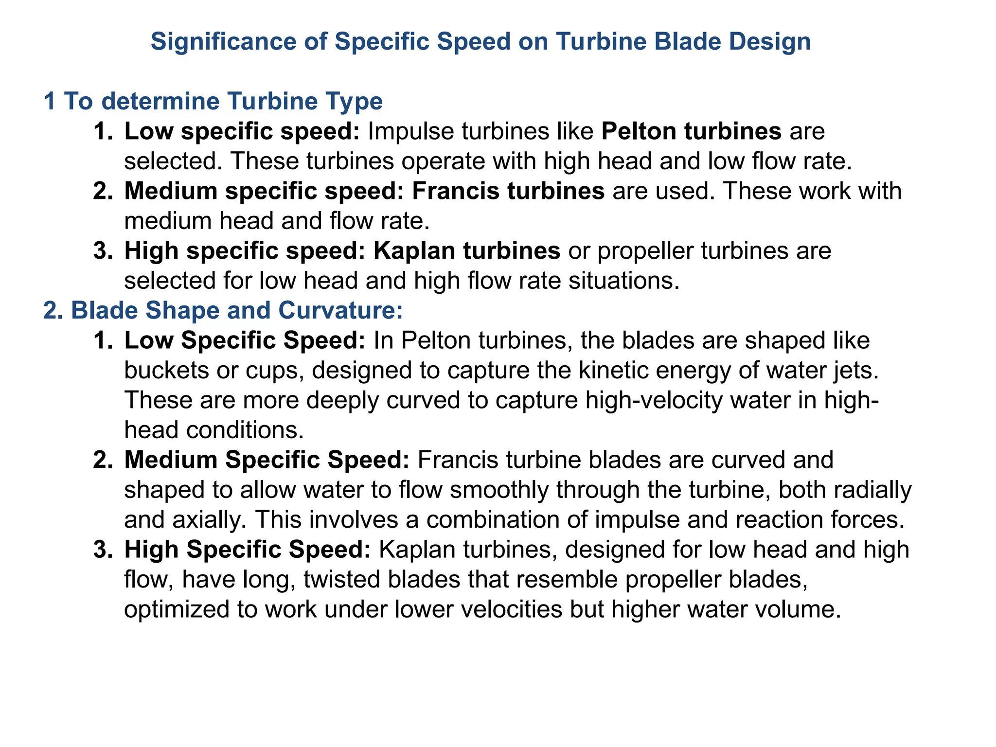
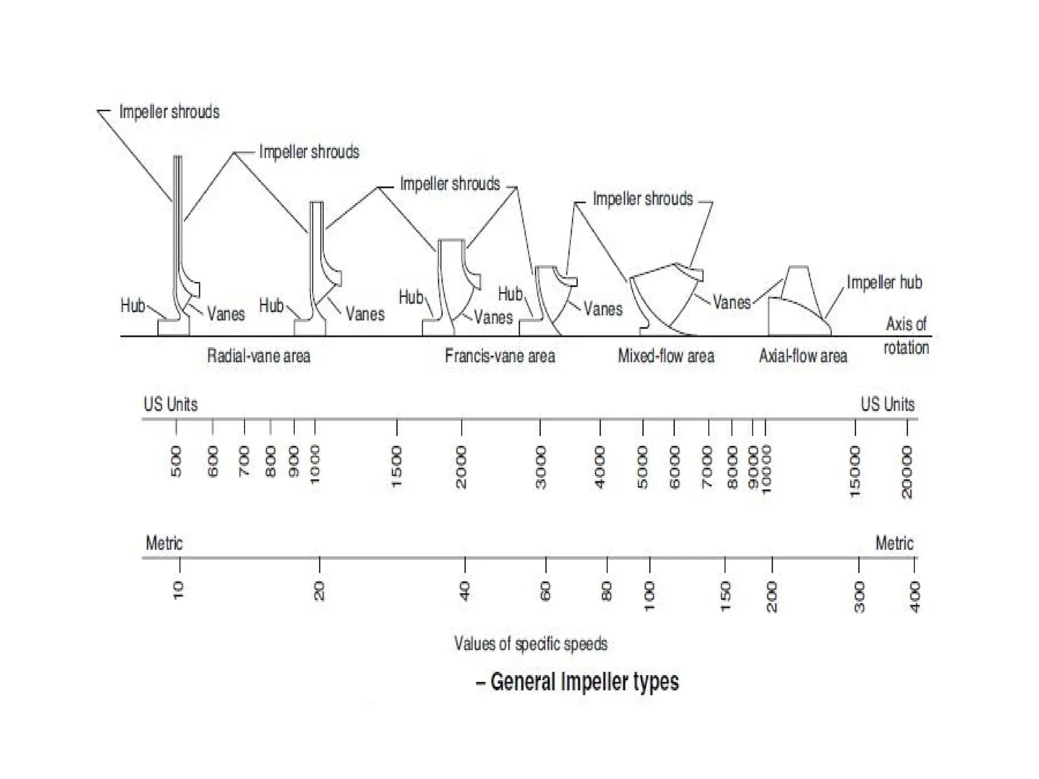
Significance of SpecificSpeed on Turbine Blade Design
1 To determine Turbine Type
1. Low specific speed: Impulse turbines like Pelton turbines are
selected. These turbines operate with high head and low flow rate.
2. Medium specific speed: Francis turbines are used. These work with
medium head and flow rate.
3. High specific speed: Kaplan turbines or propeller turbines are
selected for low head and high flow rate situations.
2. Blade Shape and Curvature:
1. Low Specific Speed: In Pelton turbines, the blades are shaped like
buckets or cups, designed to capture the kinetic energy of water jets.
These are more deeply curved to capture high-velocity water in high-
head conditions.
2. Medium Specific Speed: Francis turbine blades are curved and
shaped to allow water to flow smoothly through the turbine, both radially
and axially. This involves a combination of impulse and reaction forces.
3. High Specific Speed: Kaplan turbines, designed for low head and high
flow, have long, twisted blades that resemble propeller blades,
optimized to work under lower velocities but higher water volume.
45.
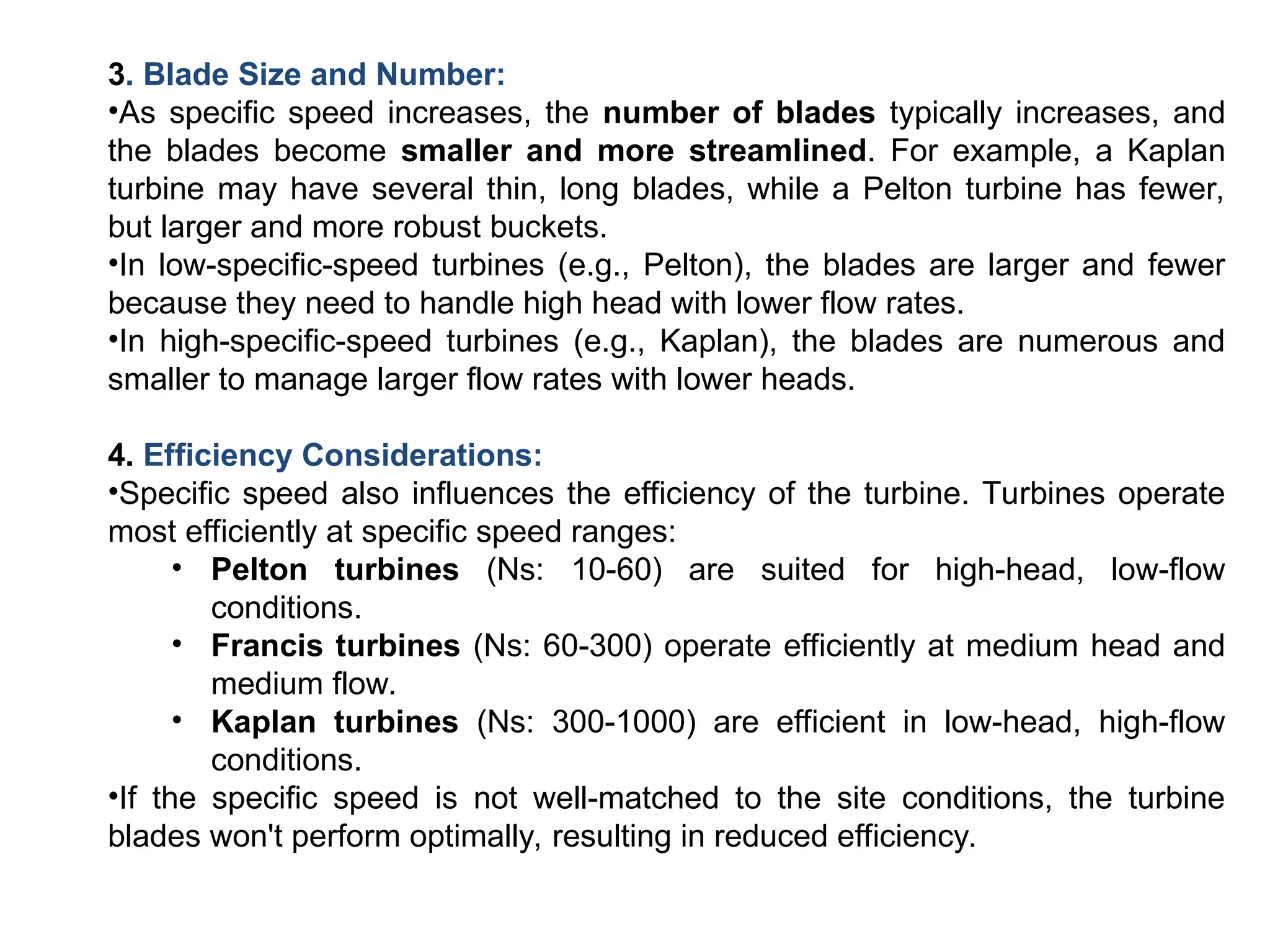
3. Blade Sizeand Number:
•As specific speed increases, the number of blades typically increases, and
the blades become smaller and more streamlined. For example, a Kaplan
turbine may have several thin, long blades, while a Pelton turbine has fewer,
but larger and more robust buckets.
•In low-specific-speed turbines (e.g., Pelton), the blades are larger and fewer
because they need to handle high head with lower flow rates.
•In high-specific-speed turbines (e.g., Kaplan), the blades are numerous and
smaller to manage larger flow rates with lower heads.
4. Efficiency Considerations:
•Specific speed also influences the efficiency of the turbine. Turbines operate
most efficiently at specific speed ranges:
• Pelton turbines (Ns: 10-60) are suited for high-head, low-flow
conditions.
• Francis turbines (Ns: 60-300) operate efficiently at medium head and
medium flow.
• Kaplan turbines (Ns: 300-1000) are efficient in low-head, high-flow
conditions.
•If the specific speed is not well-matched to the site conditions, the turbine
blades won't perform optimally, resulting in reduced efficiency.
46.
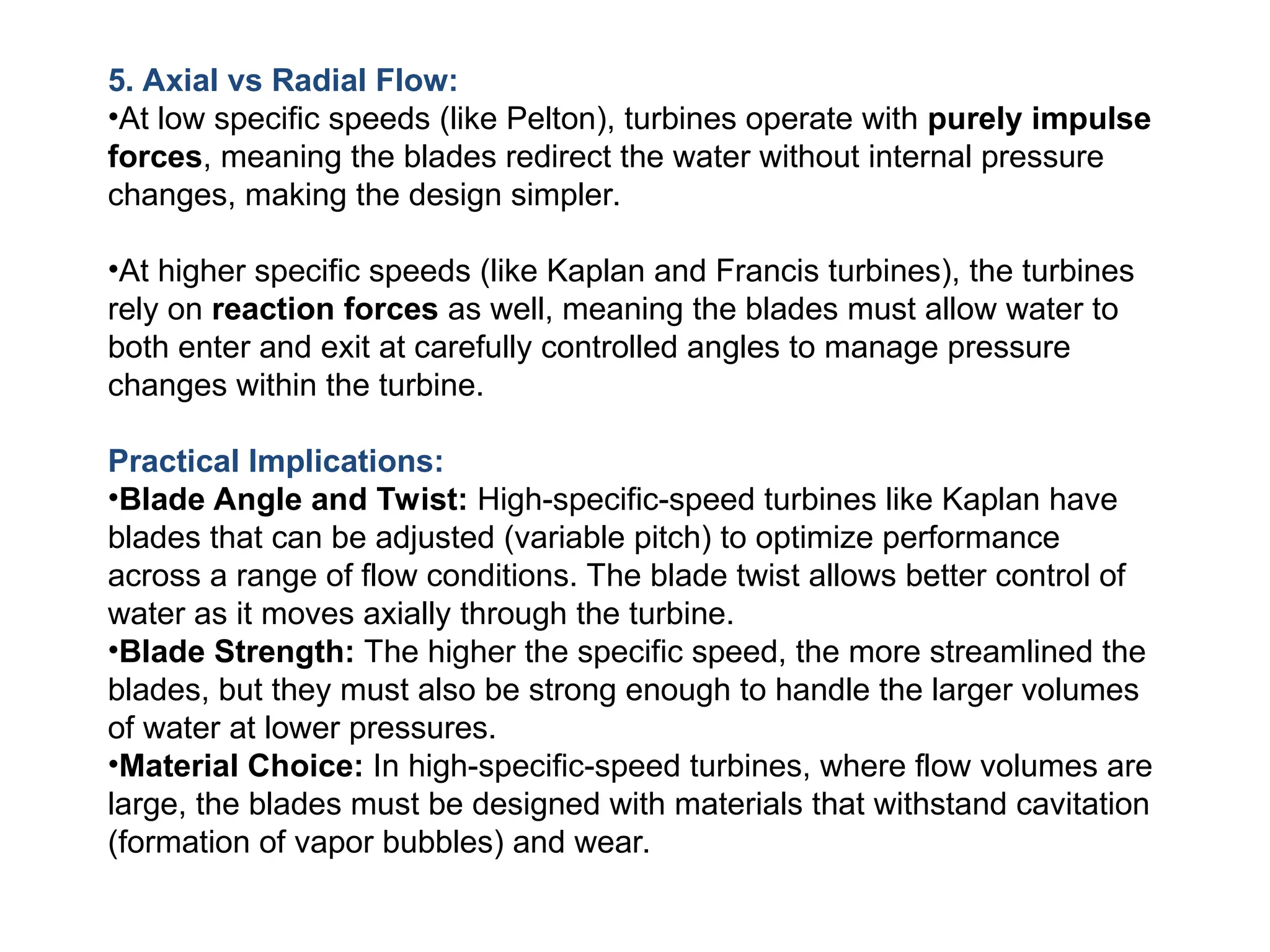
5. Axial vsRadial Flow:
•At low specific speeds (like Pelton), turbines operate with purely impulse
forces, meaning the blades redirect the water without internal pressure
changes, making the design simpler.
•At higher specific speeds (like Kaplan and Francis turbines), the turbines
rely on reaction forces as well, meaning the blades must allow water to
both enter and exit at carefully controlled angles to manage pressure
changes within the turbine.
Practical Implications:
•Blade Angle and Twist: High-specific-speed turbines like Kaplan have
blades that can be adjusted (variable pitch) to optimize performance
across a range of flow conditions. The blade twist allows better control of
water as it moves axially through the turbine.
•Blade Strength: The higher the specific speed, the more streamlined the
blades, but they must also be strong enough to handle the larger volumes
of water at lower pressures.
•Material Choice: In high-specific-speed turbines, where flow volumes are
large, the blades must be designed with materials that withstand cavitation
(formation of vapor bubbles) and wear.
47.
Conclusion
Specific speed directlydictates the type of turbine and the design of its
blades. It governs the blade's shape, size, curvature, and number,
ensuring that the turbine can operate efficiently under the given head and
flow conditions. Understanding and optimizing specific speed during
design ensures that the turbine maximizes energy extraction while
minimizing wear, cavitation, and inefficiencies.
50
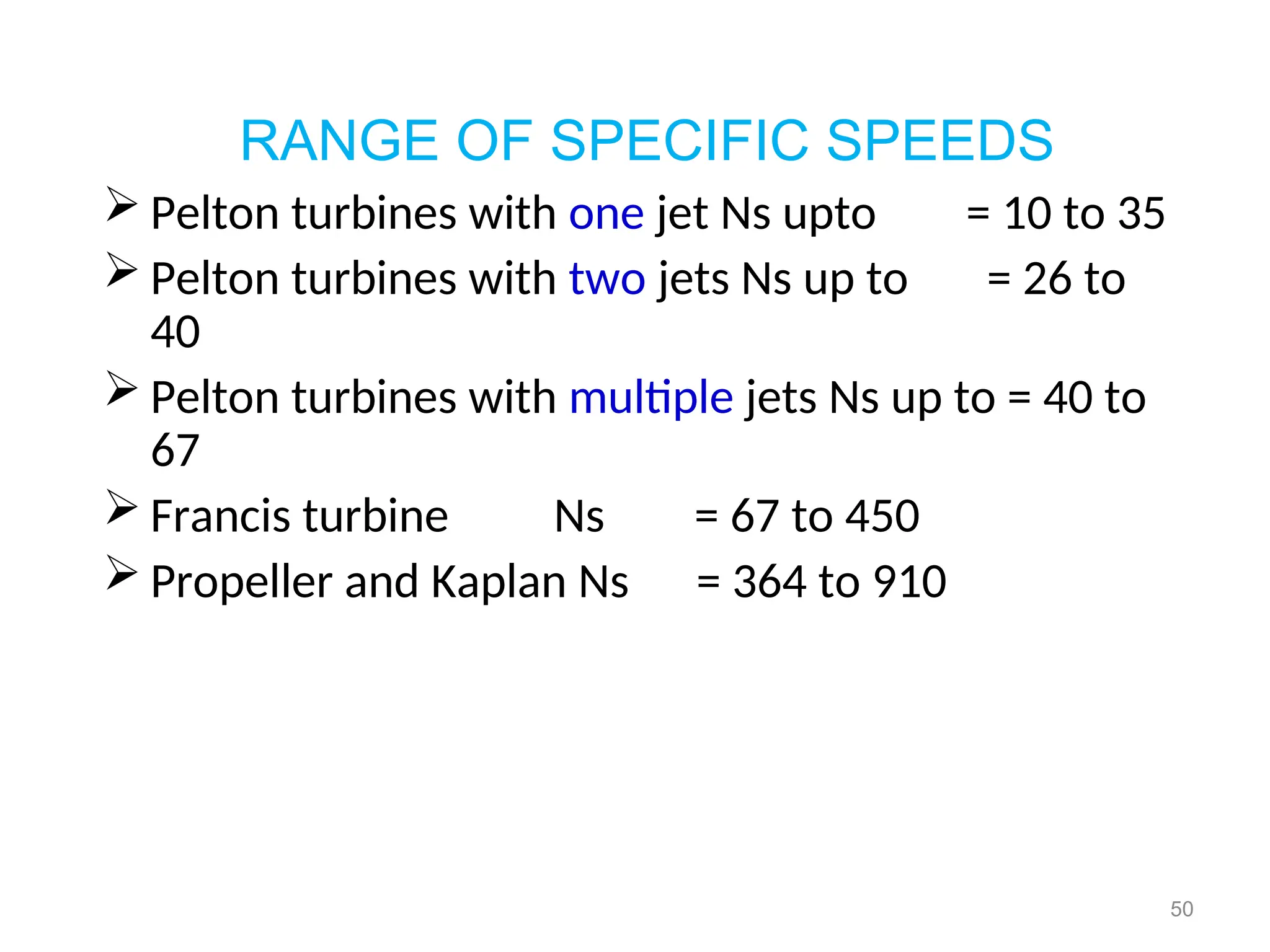
RANGE OF SPECIFICSPEEDS
Pelton turbines with one jet Ns upto = 10 to 35
Pelton turbines with two jets Ns up to = 26 to
40
Pelton turbines with multiple jets Ns up to = 40 to
67
Francis turbine Ns = 67 to 450
Propeller and Kaplan Ns = 364 to 910
52.
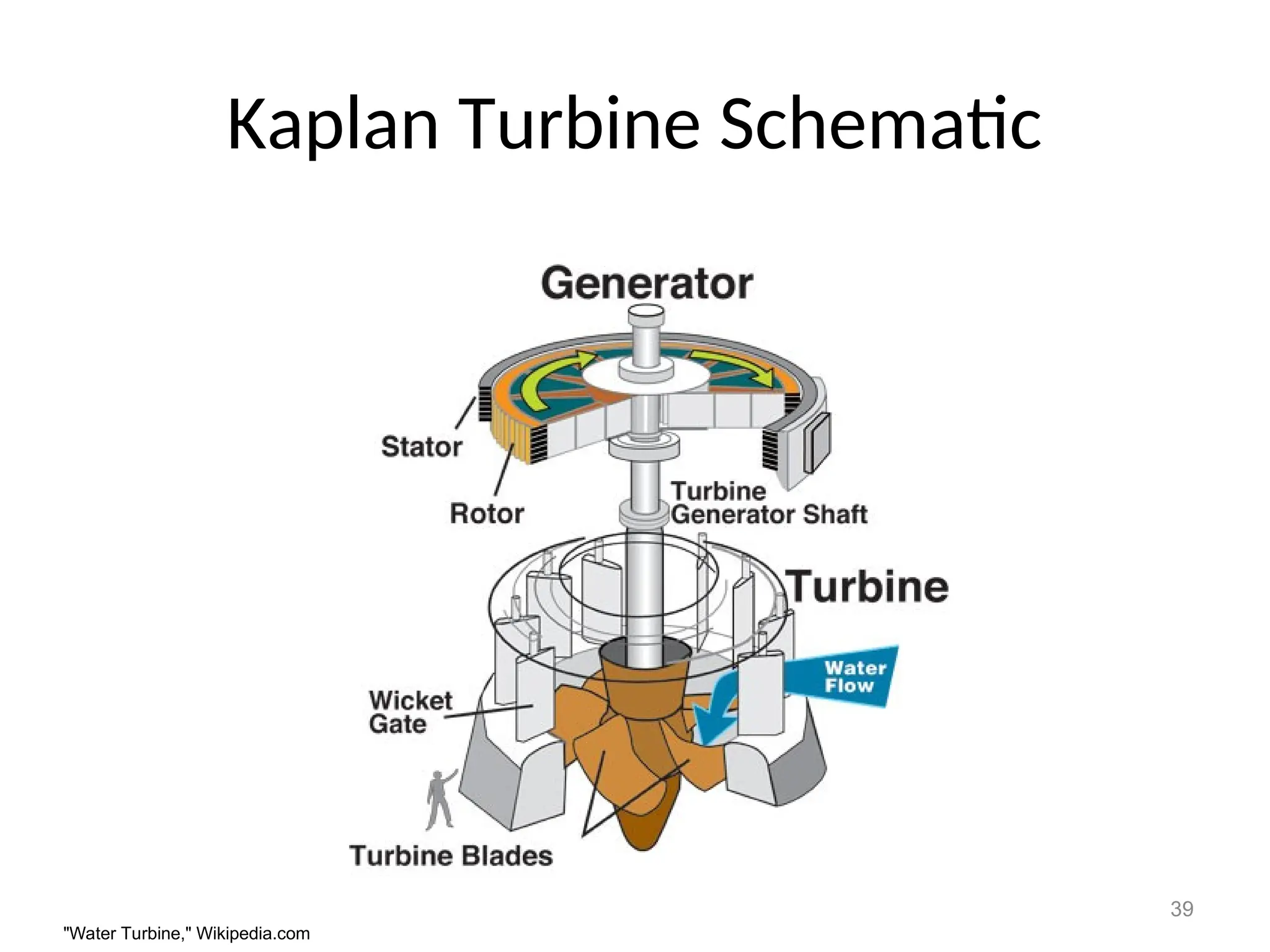
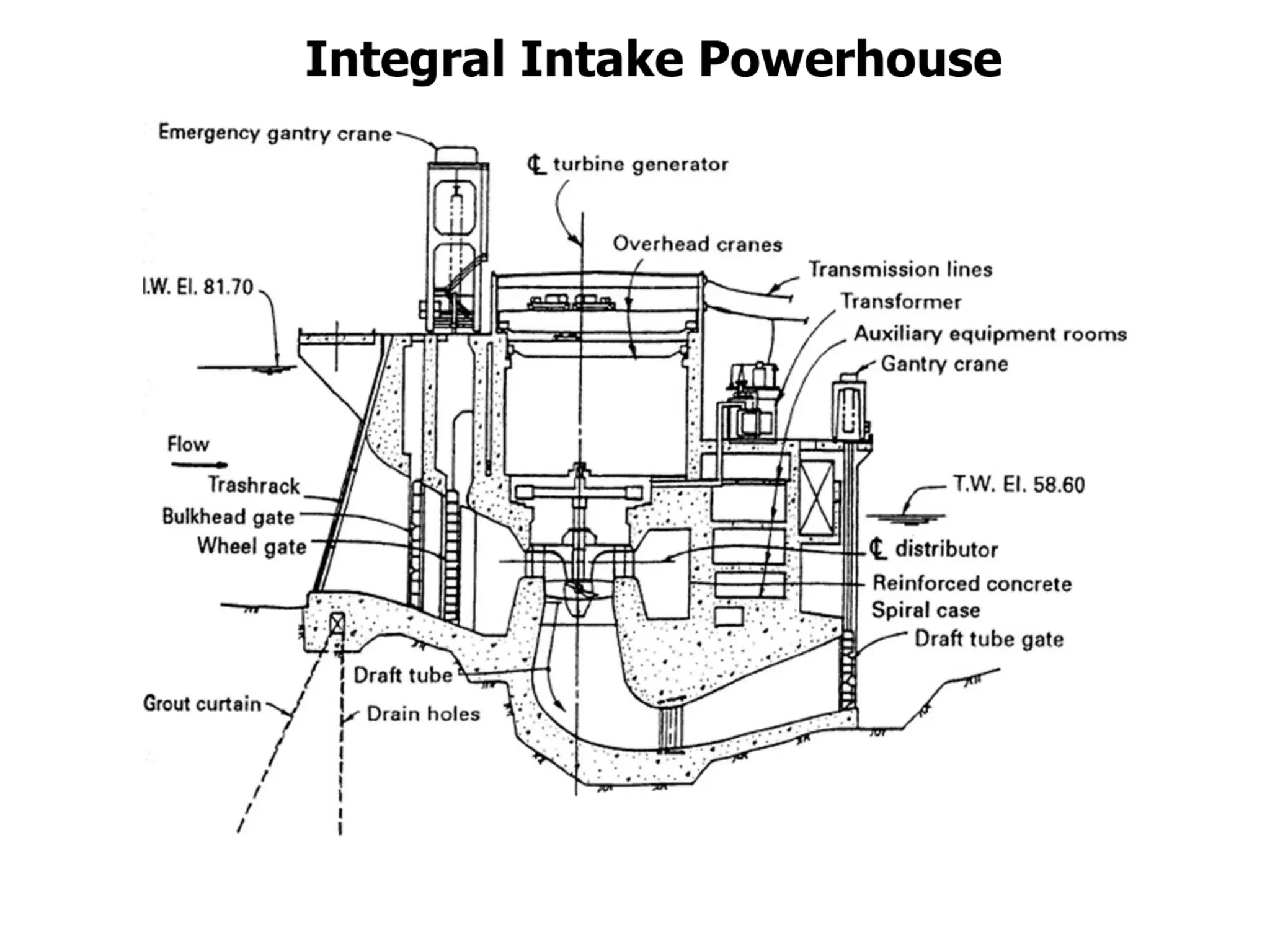
The powerhouses containthe turbine, generator, control equipment,
transformers, and supporting auxiliary equipment.
Below the turbines are the draft tubes and their gates
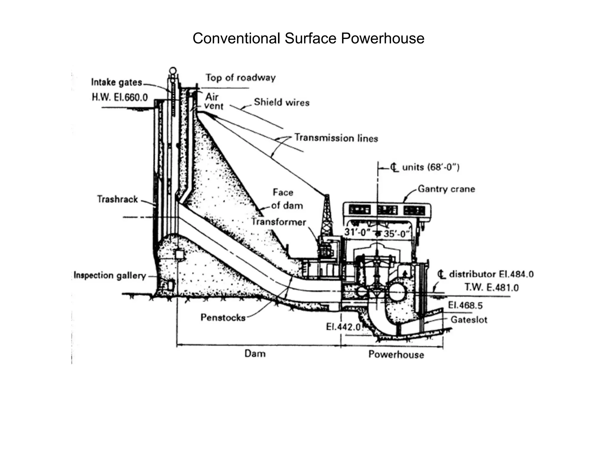
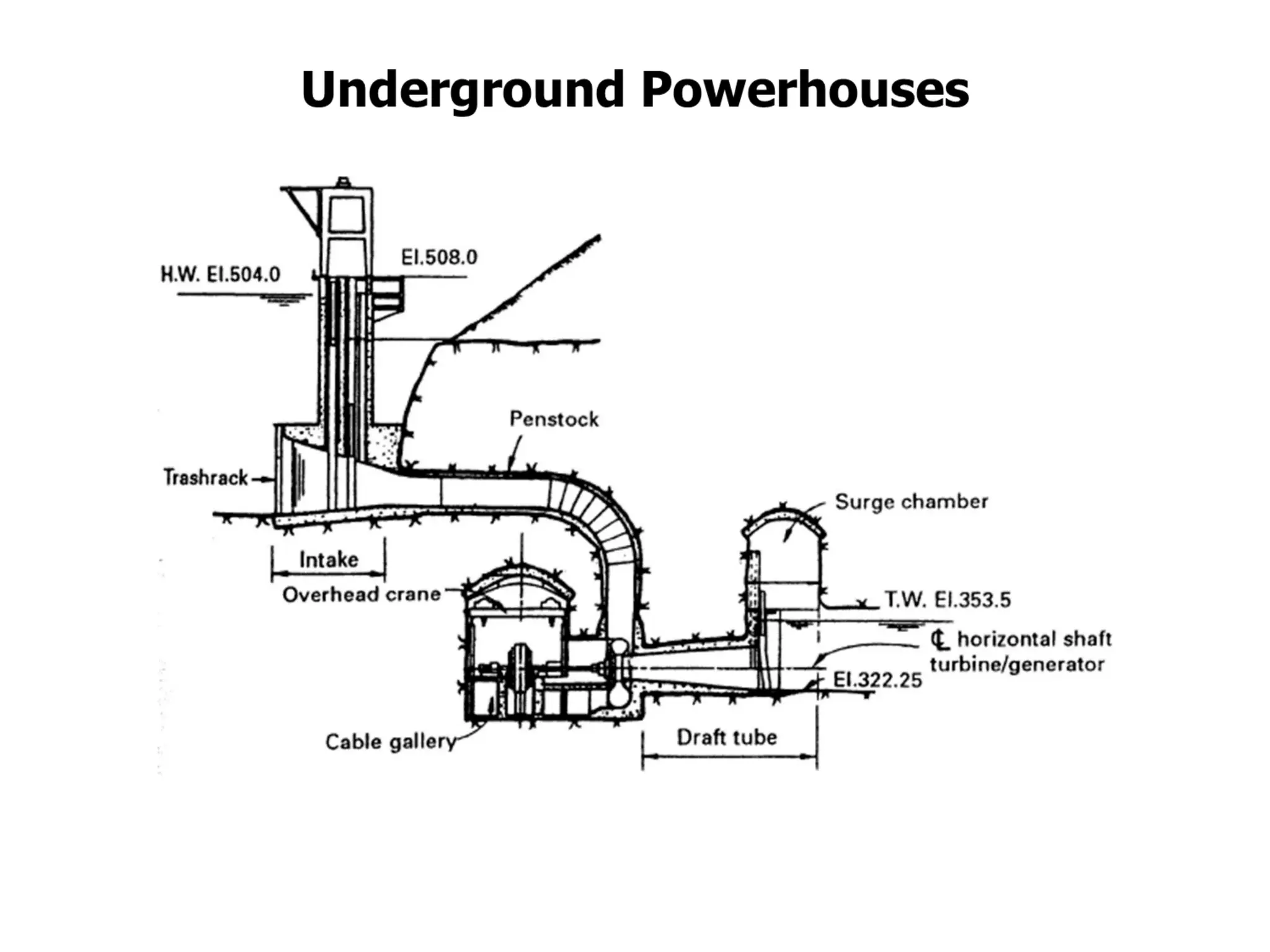
Types of powerhouses:
•Integral intake powerhouse
•Conventional surface powerhouse
•Underground powerhouse
Powerhouses
An integral intakepowerhouse refers to a type of hydroelectric power station
where the intake structure (where water enters the system) and the powerhouse
(where electricity is generated) are combined into a single, integrated structure. This
design is common in run-of-river hydroelectric plants and smaller-scale hydro
projects where the water intake and the turbine-generating components are co-
located to improve efficiency, reduce construction costs, and minimize environmental
impact.
Key Features:
1.Integrated Design: The intake, which directs water from the river or reservoir, is
built together with the powerhouse. This reduces the need for long penstocks (pipes
or tunnels) and simplifies the layout.
2.Run-of-River Projects: Typically used in low-head hydroelectric projects, where
water flows directly from the river to generate electricity, without the need for large
dams or reservoirs.
3.Compact Structure: The integrated design makes the power station more
compact, which can be especially beneficial in areas where space is limited or
environmental regulations are strict.
4.Efficient Operation: Since the water intake and turbines are co-located, energy
loss from water transport is minimized, leading to greater efficiency.
57.
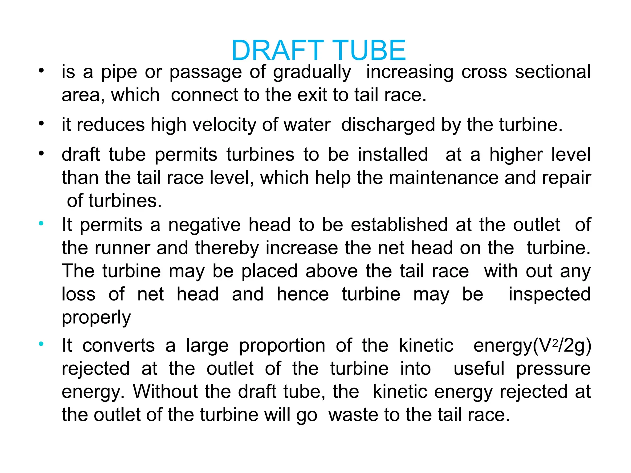
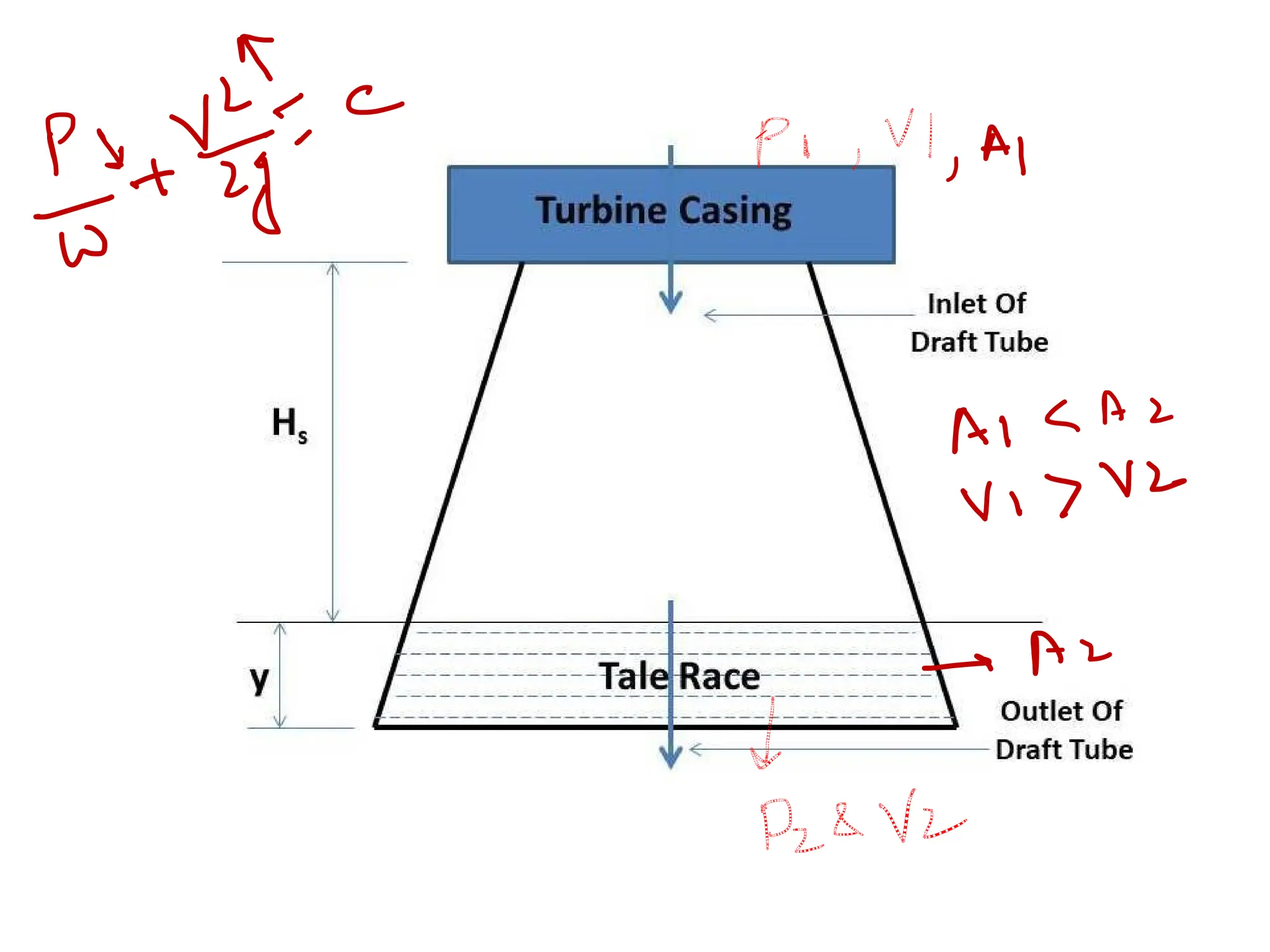
DRAFT TUBE
• isa pipe or passage of gradually increasing cross sectional
area, which connect to the exit to tail race.
• it reduces high velocity of water discharged by the turbine.
• draft tube permits turbines to be installed at a higher level
than the tail race level, which help the maintenance and repair
of turbines.
• It permits a negative head to be established at the outlet of
the runner and thereby increase the net head on the turbine.
The turbine may be placed above the tail race with out any
loss of net head and hence turbine may be inspected
properly
• It converts a large proportion of the kinetic energy(V2/2g)
rejected at the outlet of the turbine into useful pressure
energy. Without the draft tube, the kinetic energy rejected at
the outlet of the turbine will go waste to the tail race.
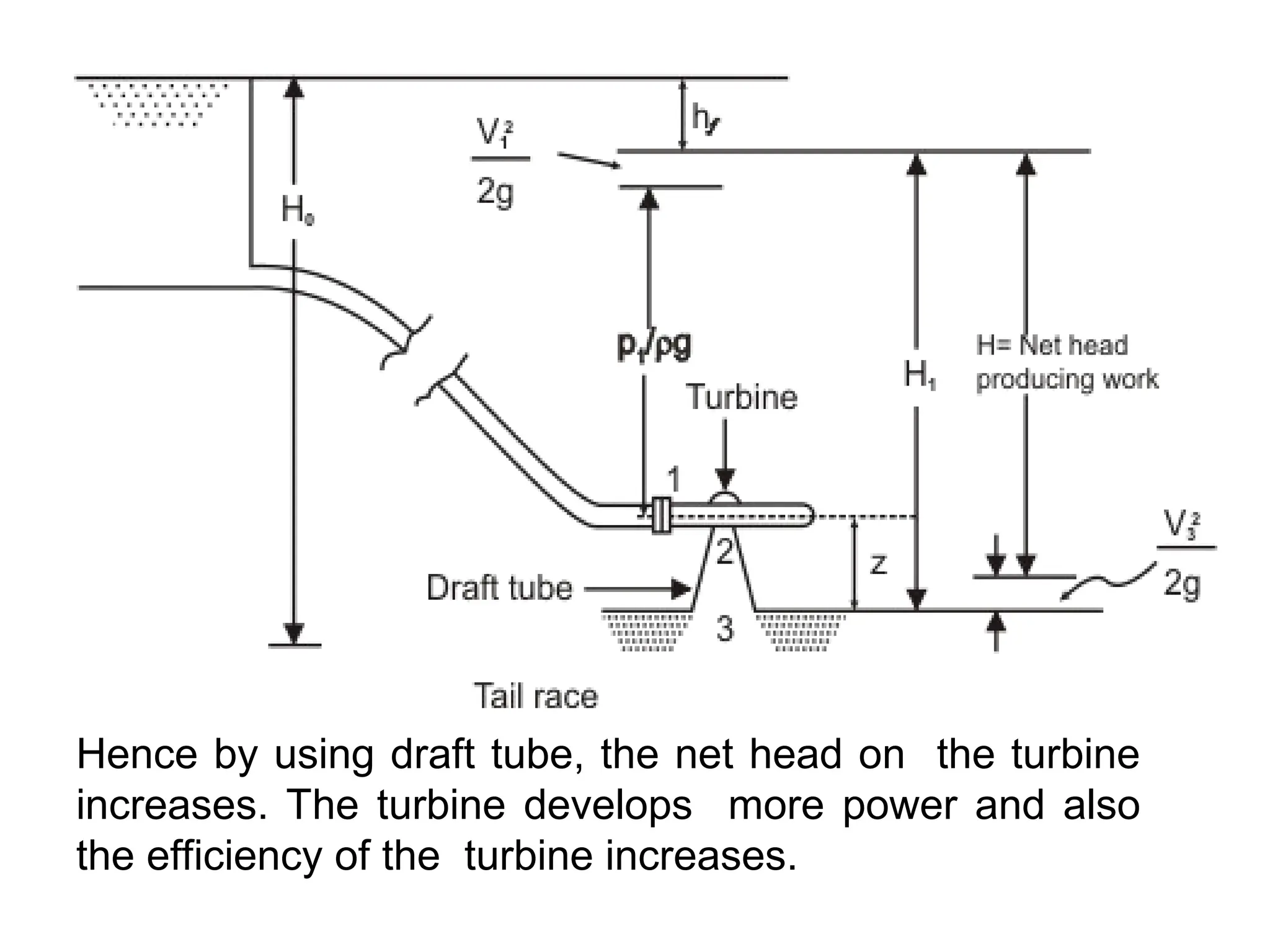
59.
Hence by usingdraft tube, the net head on the turbine
increases. The turbine develops more power and also
the efficiency of the turbine increases.
60.
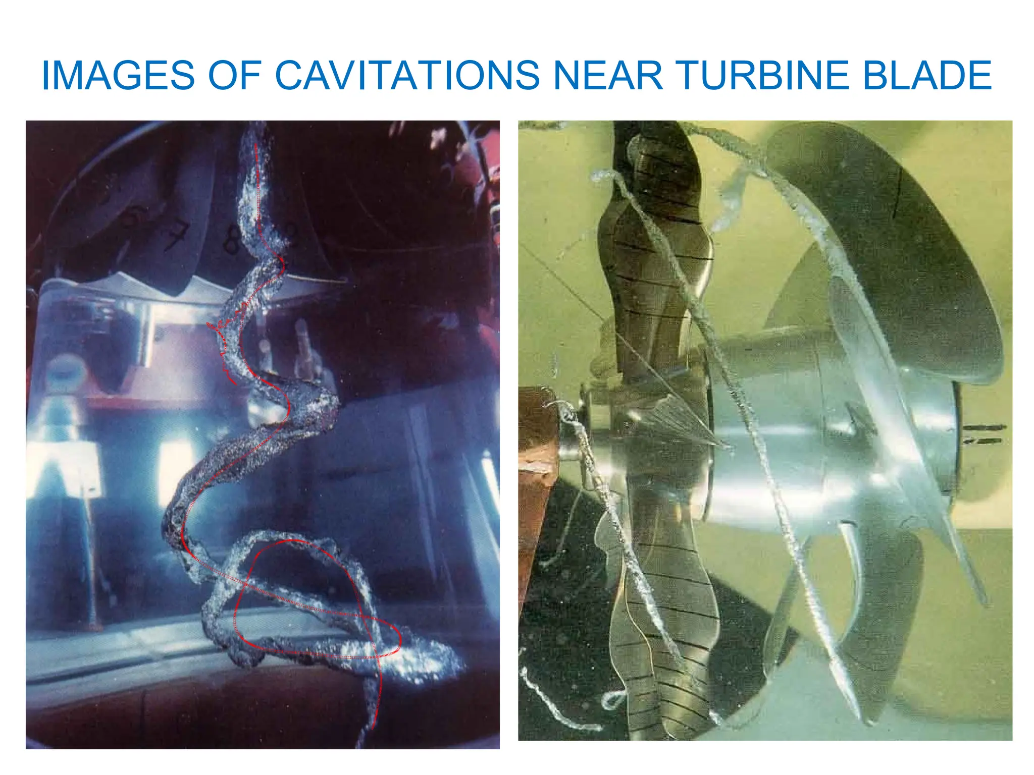
Cavitation isformation of vapor bubbles in the liquid
flowing through any Hydraulic Turbine. It describes the
phenomenon of phase changes of liquid-to-gas and gas
-to-liquid that occur when the local fluid dynamic
pressures in areas of accelerated flow drop below the
vapor pressure of the local fluid. the liquid boils and
large number of small bubbles of vapors are formed.
These bubbles mainly formed on account of low
pressure are carried by the stream to higher pressure
zones where the vapors condense and the bubbles
suddenly collapse, as the vapors are condensed to
liquid again.
Cavitation is most likely to occur near the fast moving
blades of the turbines and in the exit region of the
turbines.
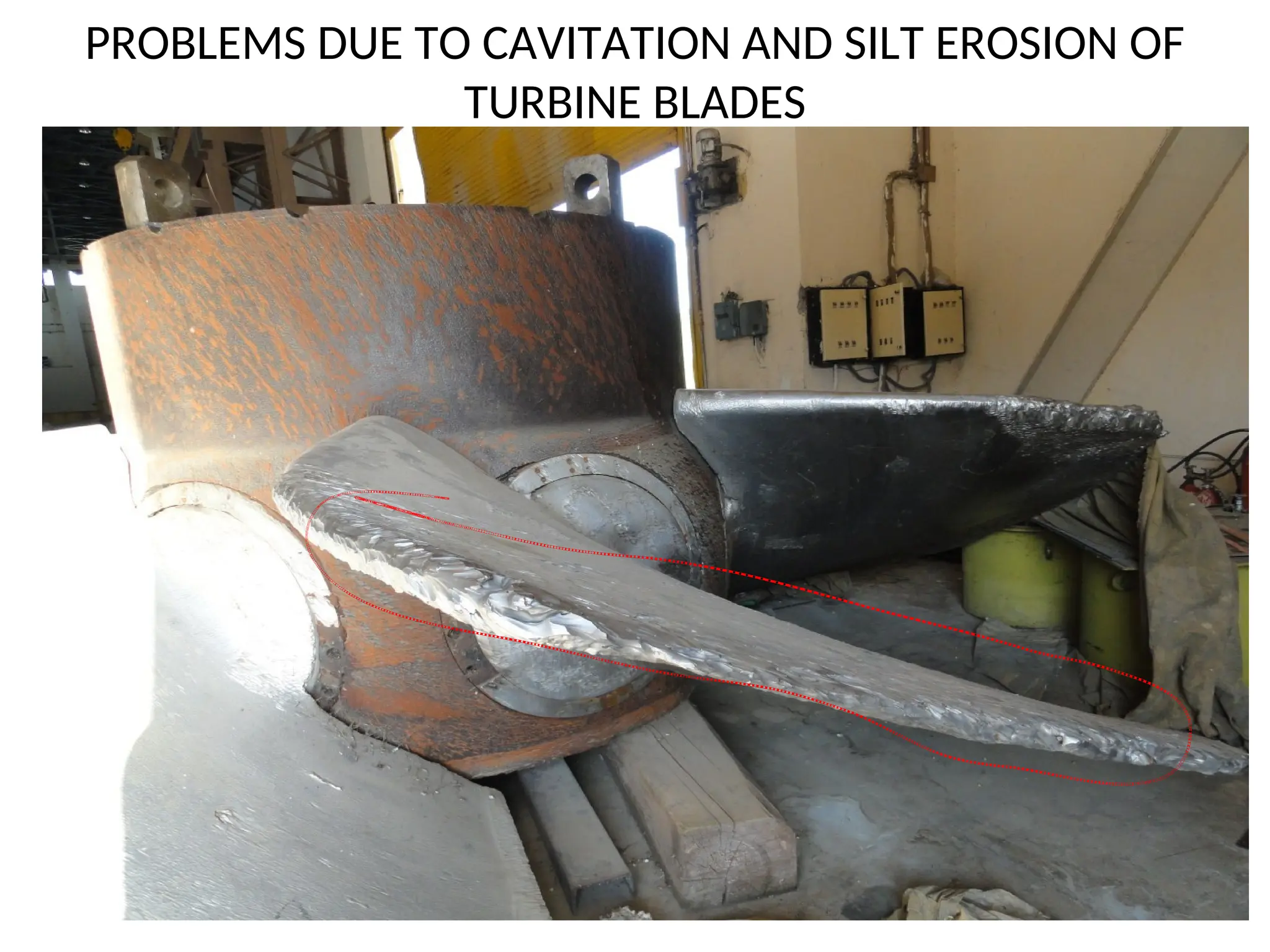
CAVITATION IN HYDRO TURBINE
61.
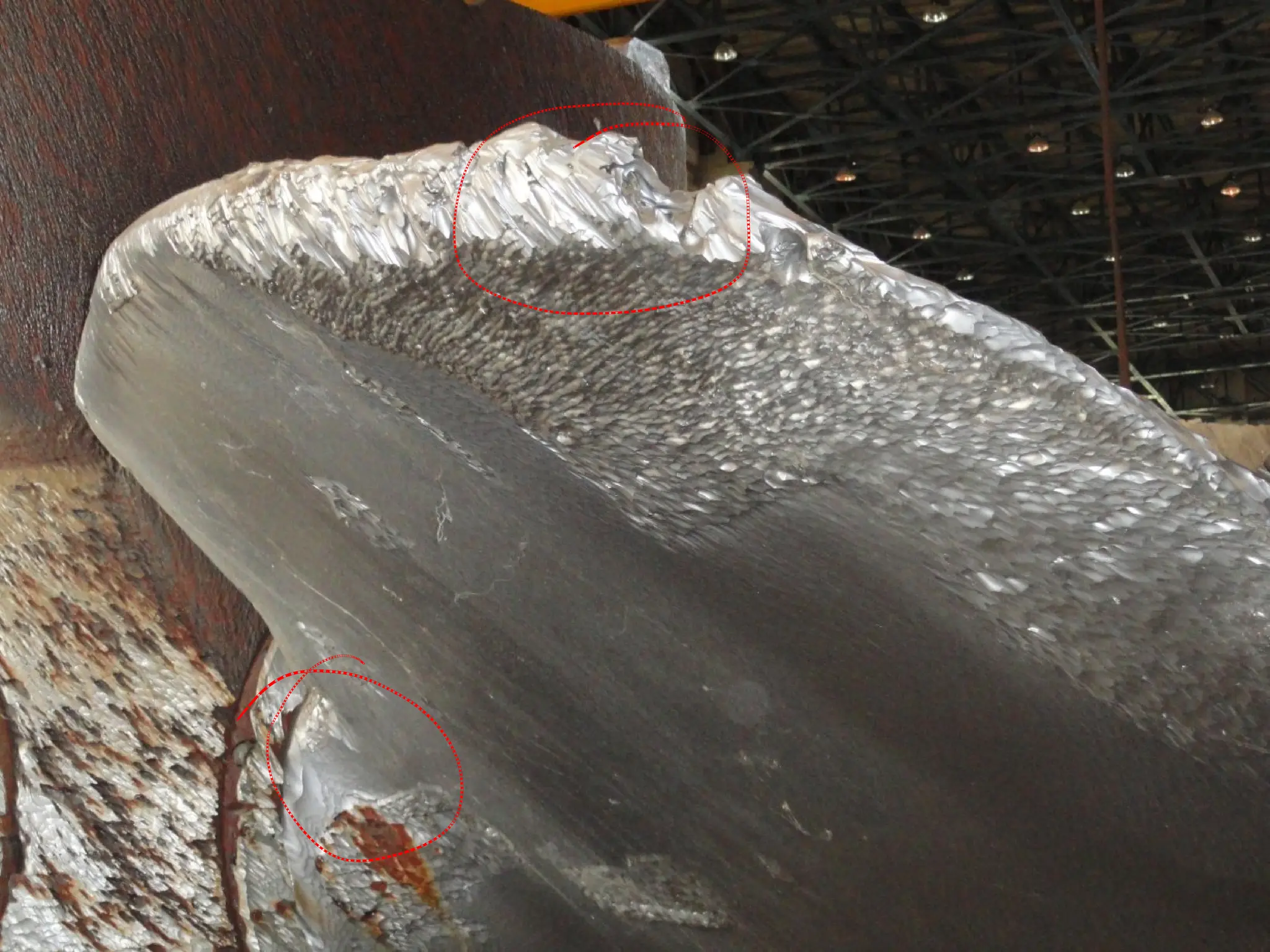
PROBLEMS DUE TOCAVITATION AND SILT EROSION OF
TURBINE BLADES