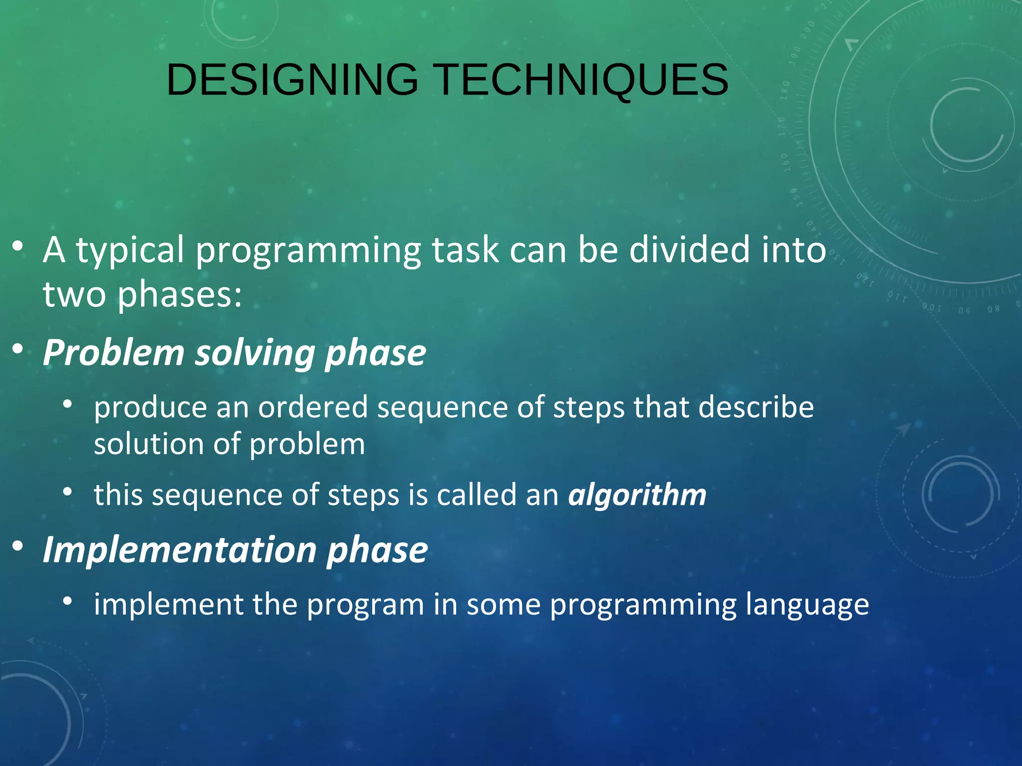
Program Designing techniques
Introduction to Computing
Lecture# 24,25
PROGRAM DESIGNING TECHNIQUES
Pseudocode
 Algorithm
Flowchart
DESIGNING TECHNIQUES
• A typical programming task can be divided into
two phases:
• Problem solving phase
• produce an ordered sequence of steps that describe
solution of problem
• this sequence of steps is called an algorithm
• Implementation phase
• implement the program in some programming language
STEPS IN PROBLEM SOLVING
• First produce a general algorithm (one can use
pseudocode)
• Refine the algorithm successively to get step by
step detailed algorithm that is very close to a
computer language.
• Pseudocode is an artificial and informal language
that helps programmers develop algorithms.
• Pseudocode is very similar to everyday English.
PSEUDOCODE & ALGORITHM
• Example 1: Write a pseudocode and an algorithm to convert the length in feet
to inches.
EXAMPLE 2
Pseudocode:
• Input the length in feet
• Calculate the length in inches by multiplying length in feet with 12
• Print length in inches.
EXAMPLE 2
Algorithm
• Step 1: Input L_ft
• Step 2: L_inches ← L_ft x 12
• Step 3: Print L_inches
THE FLOWCHART
• A schematic representation of a sequence of operations, as in a manufacturing
process or computer program.
• It is a graphic representation of how a process works, showing, at a minimum, the
sequence of steps.
• A flowchart consists of a sequence of instructions linked together by arrows to
show the order in which the instructions must be carried out.
CONT…
Each instruction is put into a box. The boxes are different shapes depending
upon what the instruction is.
Different symbols are used to draw each type of flowchart.
CONT…
A Flowchart
• shows logic of an algorithm
• emphasizes individual steps and their interconnections
• e.g. control flow from one action to the next
FLOWCHART SYMBOLS
Basic
EXAMPLE 2
• Write an algorithm and draw a flowchart to convert the length in feet to
centimeter.
Pseudocode:
• Input the length in feet (Lft)
• Calculate the length in cm (Lcm) by multiplying LFT with 30
• Print length in cm (LCM)
EXAMPLE 2
Algorithm
• Step 1: Input L_ft
• Step 2: Lcm ← L_ft x 30
• Step 3: Print L_cm
START
Input
L_ft
Lcm ← L_ft x 30
Print
L_cm
STOP
Flowchart
EXAMPLE 3
Write an algorithm and draw a flowchart that will
read the two sides of a rectangle and calculate its
area.
Pseudocode
• Input the width (W) and Length (L) of a rectangle
• Calculate the area (A) by multiplying L with W
• Print A
EXAMPLE 3
Algorithm
• Step 1: Input W,L
• Step 2: A ← L x W
• Step 3: Print A
START
Input
W, L
A ← L x W
Print
A
STOP
EXAMPLE 4
• Write an algorithm and draw a flowchart that
will calculate the roots of a quadratic equation
• Hint: d = sqrt ( ), and the roots are: x1 =
(–b + d)/2a and x2 = (–b – d)/2a
2
0ax bx c+ + =
2
4b ac−
EXAMPLE 4
Pseudocode:
• Input the coefficients (a, b, c) of the quadratic equation
• Calculate d
• Calculate x1
• Calculate x2
• Print x1 and x2
EXAMPLE 4
• Algorithm:
• Step 1: Input a, b, c
• Step 2: d ← sqrt ( )
• Step 3: x1 ← (–b + d) / (2 x a)
• Step 4: x2 ← (–b – d) / (2 x a)
• Step 5: Print x1, x2
4b b a c× − × ×
START
Input
a, b, c
d ← sqrt(b x b – 4 x a x c)
Print
x1 ,x2
STOP
x1 ←(–b + d) / (2 x a)
X2 ← (–b – d) / (2 x a)
DECISION STRUCTURES
• The expression A>B is a logical expression
• it describes a condition we want to test
• if A>B is true (if A is greater than B) we take the
action on left
• print the value of A
• if A>B is false (if A is not greater than B) we take
the action on right
• print the value of B
DECISION STRUCTURES
is
A>B
Print
B
Print
A
Y N
IF–THEN–ELSE STRUCTURE
• The structure is as follows
If condition then
true alternative
else
false alternative
endif
IF–THEN–ELSE STRUCTURE
If A>B then
print A
else
print B
endif
is
A>B
Print
B
Print
A
Y N
RELATIONAL OPERATORS
Relational Operators
Operator Description
> Greater than
< Less than
= Equal to
≥ Greater than or equal to
≤ Less than or equal to
≠ Not equal to
EXAMPLE 5
• Write an algorithm that reads two values, determines the
largest value and prints the largest value with an identifying
message.
ALGORITHM
Step 1: Input VALUE1, VALUE2
Step 2: if (VALUE1 > VALUE2) then
MAX ← VALUE1
else
MAX ← VALUE2
endif
Step 3: Print “The largest value is”, MAX
EXAMPLE 5
MAX ← VALUE1
Print
“The largest value is”,
MAX
STOP
Y N
START
Input
VALUE1,VALUE2
MAX ← VALUE2
is
VALUE1>VALUE2
NESTED IFS
• One of the alternatives within an IF–THEN–ELSE statement
• may involve further IF–THEN–ELSE statement
EXAMPLE 6
• Write an algorithm that reads three numbers and prints the value of the largest
number.
EXAMPLE 6
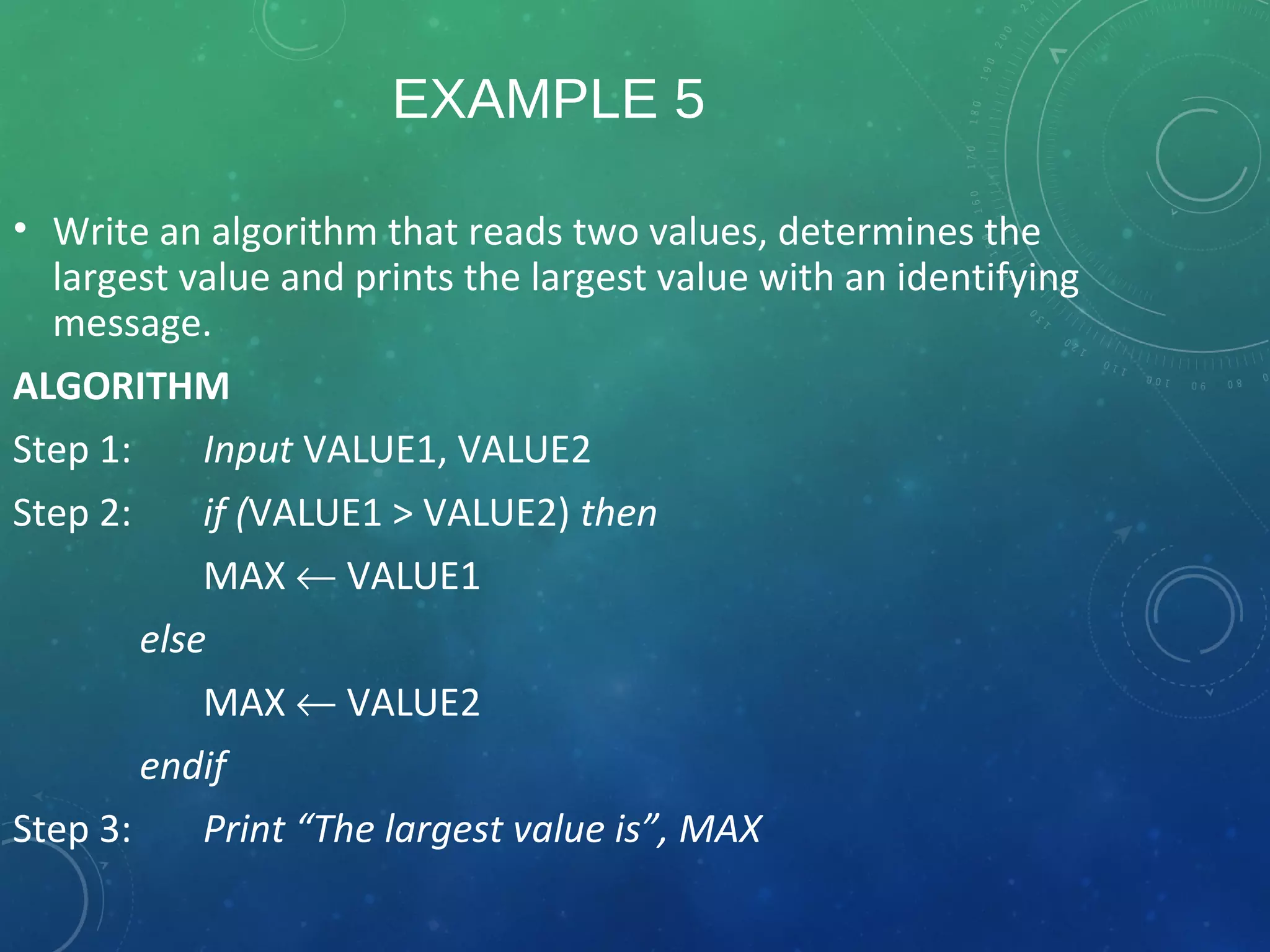
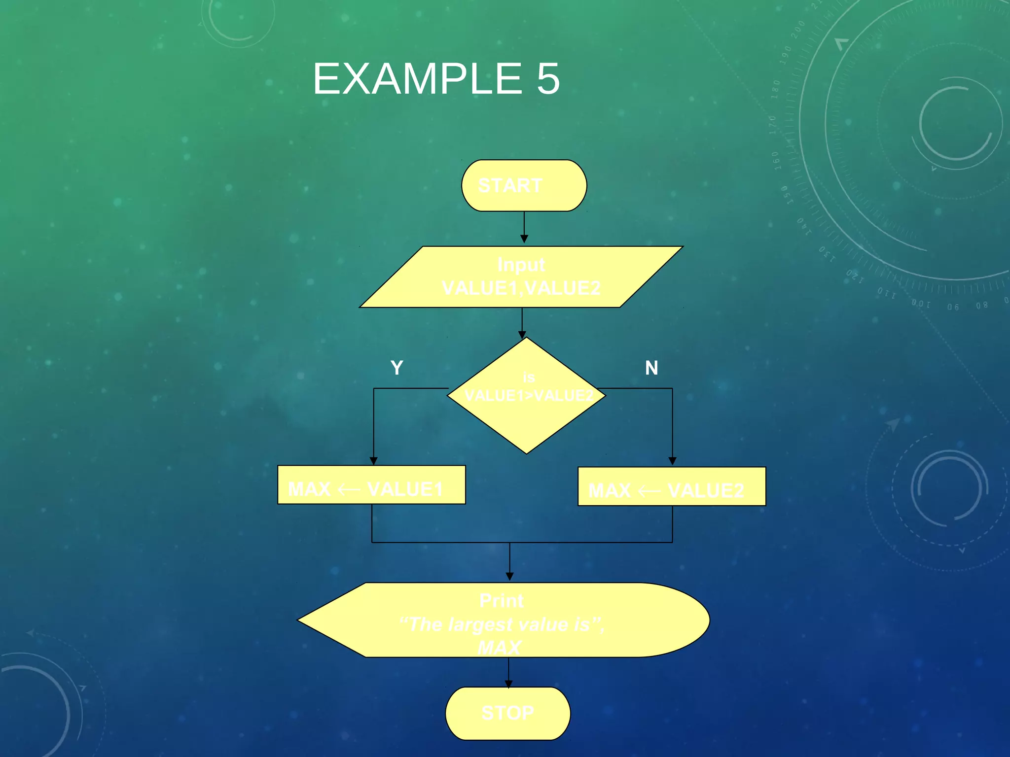
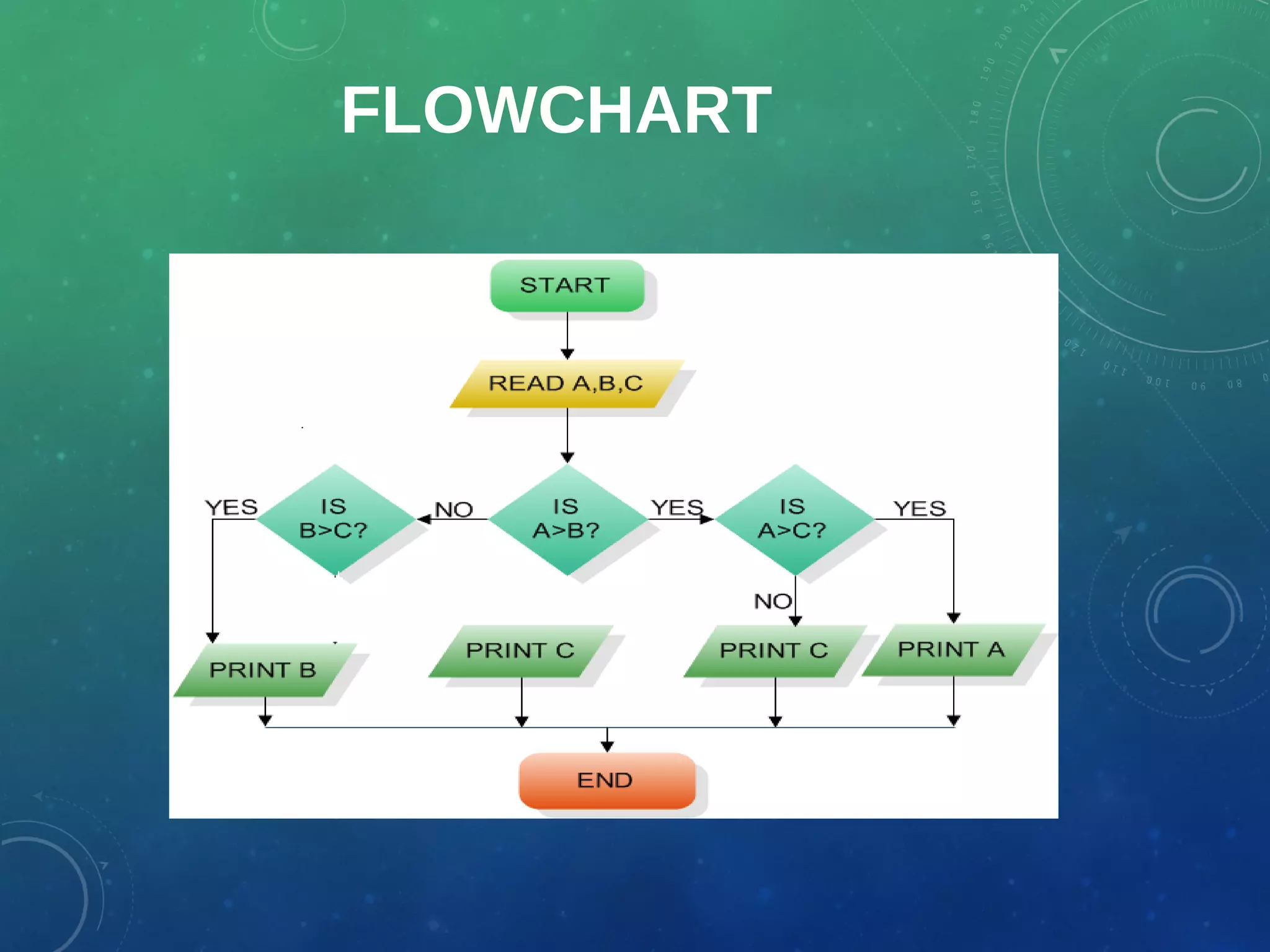
Step 1: Input N1, N2, N3
Step 2: if (N1>N2) then
if (N1>N3) then
MAX ← N1 [N1>N2, N1>N3]
else
MAX ← N3 [N3>N1>N2]
endif
else
if (N2>N3) then
MAX ← N2 [N2>N1, N2>N3]
else
MAX ← N3 [N3>N2>N1]
endif
endif
Step 3: Print “The largest number is”, MAX
EXAMPLE 6
• Flowchart: Draw the flowchart of the above Algorithm.
FLOWCHART
NO
EXAMPLE 7
• Write and algorithm and draw a flowchart to read an employee name
(NAME), overtime hours worked (OVERTIME), hours absent (ABSENT) and
determine the bonus payment (PAYMENT).
EXAMPLE 7
Bonus Schedule
OVERTIME – (2/3)*ABSENT Bonus Paid
>40 hours
>30 but ≤ 40 hours
>20 but ≤ 30 hours
>10 but ≤ 20 hours
≤ 10 hours
$50
$40
$30
$20
$10
Step 1: Input NAME,OVERTIME,ABSENT
Step 2: if (OVERTIME–(2/3)*ABSENT > 40 ) then
PAYMENT ← 50
else if (OVERTIME–(2/3)*ABSENT > 30 &&
OVERTIME–(2/3)*ABSENT<= 40 ) then
PAYMENT ← 40
else if (OVERTIME–(2/3)*ABSENT > 20 &&
OVERTIME–(2/3)*ABSENT<= 30 ) then
PAYMENT ← 30
Algorithm
else if (OVERTIME–(2/3)*ABSENT > 10 &&
OVERTIME–(2/3)*ABSENT<= 20) then
PAYMENT ←20
else
PAYMENT ← 10
endif
Step 3: Print “Bonus for”, NAME “is $”,
PAYMENT
EXAMPLE 7
• Flowchart: Draw the flowchart of the above algorithm?
LOOPS
• Computers are particularly well suited to applications in which operations are
repeated many times.
• If the same task is repeated over and over again a loop can be used to reduce
program size and complexity
FLOWCHART FOR FINDING THE SUM OF FIRST FIVE
NATURAL NUMBERS
( I.E. 1,2,3,4,5):
Example 8:
EXAMPLE 9
Flowchart to find the sum of first 50 natural numbers.
EXAMPLE 10
• Write down an algorithm and draw a flowchart to find and print the largest of N (N can
be any number) numbers. (Assume N to be 5 and the following set to be the numbers {1
4 2 6 8 })
ALGORITHM:
• Step 1: Input N
• Step 2: Input Current
• Step 3: Max  Current
• Step 4: Counter 1
• Step 5: While (Counter < N)
Repeat steps 5 through 8
• Step 6: Counter  Counter + 1
• Step 7: Input Next
• Step 8: If (Next > Max) then
Max  Next
endif
• Step 9: Print Max
START
Input
N, Current
Max  Current
Print
Max
STOP
Y
Counter < N
N
Counter 1
Counter  Counter +1
Input
Next
Next
>Max
Y
N
Max  Next
Flowchart
END

Program design techniques

  • 1.
    Program Designing techniques Introductionto Computing Lecture# 24,25
  • 2.
  • 3.
    DESIGNING TECHNIQUES • Atypical programming task can be divided into two phases: • Problem solving phase • produce an ordered sequence of steps that describe solution of problem • this sequence of steps is called an algorithm • Implementation phase • implement the program in some programming language
  • 4.
    STEPS IN PROBLEMSOLVING • First produce a general algorithm (one can use pseudocode) • Refine the algorithm successively to get step by step detailed algorithm that is very close to a computer language. • Pseudocode is an artificial and informal language that helps programmers develop algorithms. • Pseudocode is very similar to everyday English.
  • 5.
    PSEUDOCODE & ALGORITHM •Example 1: Write a pseudocode and an algorithm to convert the length in feet to inches.
  • 6.
    EXAMPLE 2 Pseudocode: • Inputthe length in feet • Calculate the length in inches by multiplying length in feet with 12 • Print length in inches.
  • 7.
    EXAMPLE 2 Algorithm • Step1: Input L_ft • Step 2: L_inches ← L_ft x 12 • Step 3: Print L_inches
  • 8.
    THE FLOWCHART • Aschematic representation of a sequence of operations, as in a manufacturing process or computer program. • It is a graphic representation of how a process works, showing, at a minimum, the sequence of steps. • A flowchart consists of a sequence of instructions linked together by arrows to show the order in which the instructions must be carried out.
  • 9.
    CONT… Each instruction isput into a box. The boxes are different shapes depending upon what the instruction is. Different symbols are used to draw each type of flowchart.
  • 10.
    CONT… A Flowchart • showslogic of an algorithm • emphasizes individual steps and their interconnections • e.g. control flow from one action to the next
  • 11.
  • 12.
    EXAMPLE 2 • Writean algorithm and draw a flowchart to convert the length in feet to centimeter. Pseudocode: • Input the length in feet (Lft) • Calculate the length in cm (Lcm) by multiplying LFT with 30 • Print length in cm (LCM)
  • 13.
    EXAMPLE 2 Algorithm • Step1: Input L_ft • Step 2: Lcm ← L_ft x 30 • Step 3: Print L_cm START Input L_ft Lcm ← L_ft x 30 Print L_cm STOP Flowchart
  • 14.
    EXAMPLE 3 Write analgorithm and draw a flowchart that will read the two sides of a rectangle and calculate its area. Pseudocode • Input the width (W) and Length (L) of a rectangle • Calculate the area (A) by multiplying L with W • Print A
  • 15.
    EXAMPLE 3 Algorithm • Step1: Input W,L • Step 2: A ← L x W • Step 3: Print A START Input W, L A ← L x W Print A STOP
  • 16.
    EXAMPLE 4 • Writean algorithm and draw a flowchart that will calculate the roots of a quadratic equation • Hint: d = sqrt ( ), and the roots are: x1 = (–b + d)/2a and x2 = (–b – d)/2a 2 0ax bx c+ + = 2 4b ac−
  • 17.
    EXAMPLE 4 Pseudocode: • Inputthe coefficients (a, b, c) of the quadratic equation • Calculate d • Calculate x1 • Calculate x2 • Print x1 and x2
  • 18.
    EXAMPLE 4 • Algorithm: •Step 1: Input a, b, c • Step 2: d ← sqrt ( ) • Step 3: x1 ← (–b + d) / (2 x a) • Step 4: x2 ← (–b – d) / (2 x a) • Step 5: Print x1, x2 4b b a c× − × × START Input a, b, c d ← sqrt(b x b – 4 x a x c) Print x1 ,x2 STOP x1 ←(–b + d) / (2 x a) X2 ← (–b – d) / (2 x a)
  • 19.
    DECISION STRUCTURES • Theexpression A>B is a logical expression • it describes a condition we want to test • if A>B is true (if A is greater than B) we take the action on left • print the value of A • if A>B is false (if A is not greater than B) we take the action on right • print the value of B
  • 20.
  • 21.
    IF–THEN–ELSE STRUCTURE • Thestructure is as follows If condition then true alternative else false alternative endif
  • 22.
    IF–THEN–ELSE STRUCTURE If A>Bthen print A else print B endif is A>B Print B Print A Y N
  • 23.
    RELATIONAL OPERATORS Relational Operators OperatorDescription > Greater than < Less than = Equal to ≥ Greater than or equal to ≤ Less than or equal to ≠ Not equal to
  • 24.
    EXAMPLE 5 • Writean algorithm that reads two values, determines the largest value and prints the largest value with an identifying message. ALGORITHM Step 1: Input VALUE1, VALUE2 Step 2: if (VALUE1 > VALUE2) then MAX ← VALUE1 else MAX ← VALUE2 endif Step 3: Print “The largest value is”, MAX
  • 25.
    EXAMPLE 5 MAX ←VALUE1 Print “The largest value is”, MAX STOP Y N START Input VALUE1,VALUE2 MAX ← VALUE2 is VALUE1>VALUE2
  • 26.
    NESTED IFS • Oneof the alternatives within an IF–THEN–ELSE statement • may involve further IF–THEN–ELSE statement
  • 27.
    EXAMPLE 6 • Writean algorithm that reads three numbers and prints the value of the largest number.
  • 28.
    EXAMPLE 6 Step 1:Input N1, N2, N3 Step 2: if (N1>N2) then if (N1>N3) then MAX ← N1 [N1>N2, N1>N3] else MAX ← N3 [N3>N1>N2] endif else if (N2>N3) then MAX ← N2 [N2>N1, N2>N3] else MAX ← N3 [N3>N2>N1] endif endif Step 3: Print “The largest number is”, MAX
  • 29.
    EXAMPLE 6 • Flowchart:Draw the flowchart of the above Algorithm.
  • 30.
  • 31.
    EXAMPLE 7 • Writeand algorithm and draw a flowchart to read an employee name (NAME), overtime hours worked (OVERTIME), hours absent (ABSENT) and determine the bonus payment (PAYMENT).
  • 32.
    EXAMPLE 7 Bonus Schedule OVERTIME– (2/3)*ABSENT Bonus Paid >40 hours >30 but ≤ 40 hours >20 but ≤ 30 hours >10 but ≤ 20 hours ≤ 10 hours $50 $40 $30 $20 $10
  • 33.
    Step 1: InputNAME,OVERTIME,ABSENT Step 2: if (OVERTIME–(2/3)*ABSENT > 40 ) then PAYMENT ← 50 else if (OVERTIME–(2/3)*ABSENT > 30 && OVERTIME–(2/3)*ABSENT<= 40 ) then PAYMENT ← 40 else if (OVERTIME–(2/3)*ABSENT > 20 && OVERTIME–(2/3)*ABSENT<= 30 ) then PAYMENT ← 30 Algorithm
  • 34.
    else if (OVERTIME–(2/3)*ABSENT> 10 && OVERTIME–(2/3)*ABSENT<= 20) then PAYMENT ←20 else PAYMENT ← 10 endif Step 3: Print “Bonus for”, NAME “is $”, PAYMENT
  • 35.
    EXAMPLE 7 • Flowchart:Draw the flowchart of the above algorithm?
  • 36.
    LOOPS • Computers areparticularly well suited to applications in which operations are repeated many times. • If the same task is repeated over and over again a loop can be used to reduce program size and complexity
  • 37.
    FLOWCHART FOR FINDINGTHE SUM OF FIRST FIVE NATURAL NUMBERS ( I.E. 1,2,3,4,5): Example 8:
  • 38.
    EXAMPLE 9 Flowchart tofind the sum of first 50 natural numbers.
  • 39.
    EXAMPLE 10 • Writedown an algorithm and draw a flowchart to find and print the largest of N (N can be any number) numbers. (Assume N to be 5 and the following set to be the numbers {1 4 2 6 8 })
  • 40.
    ALGORITHM: • Step 1:Input N • Step 2: Input Current • Step 3: Max  Current • Step 4: Counter 1 • Step 5: While (Counter < N) Repeat steps 5 through 8 • Step 6: Counter  Counter + 1 • Step 7: Input Next • Step 8: If (Next > Max) then Max  Next endif • Step 9: Print Max
  • 41.
    START Input N, Current Max Current Print Max STOP Y Counter < N N Counter 1 Counter  Counter +1 Input Next Next >Max Y N Max  Next Flowchart
  • 42.