Downloaded 1,588 times
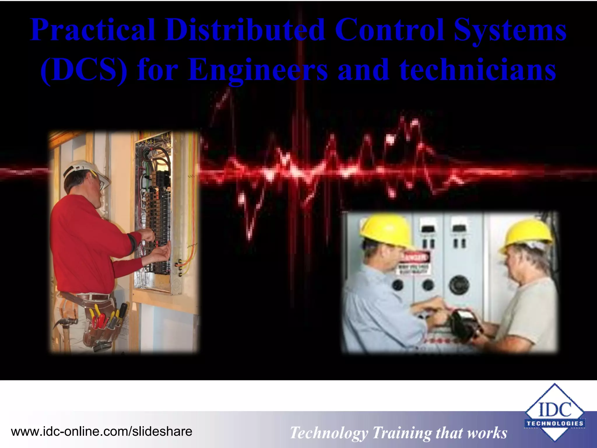
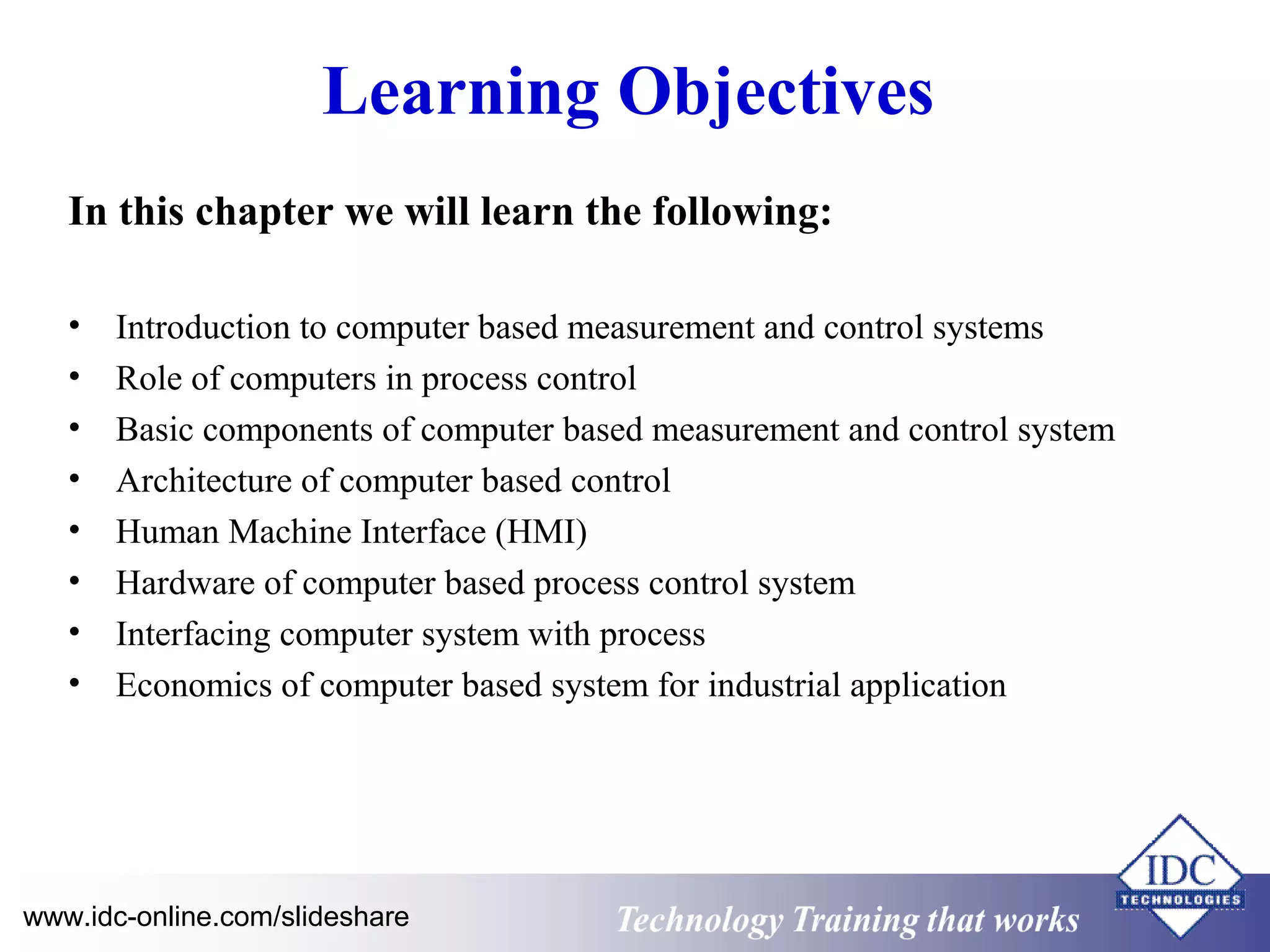
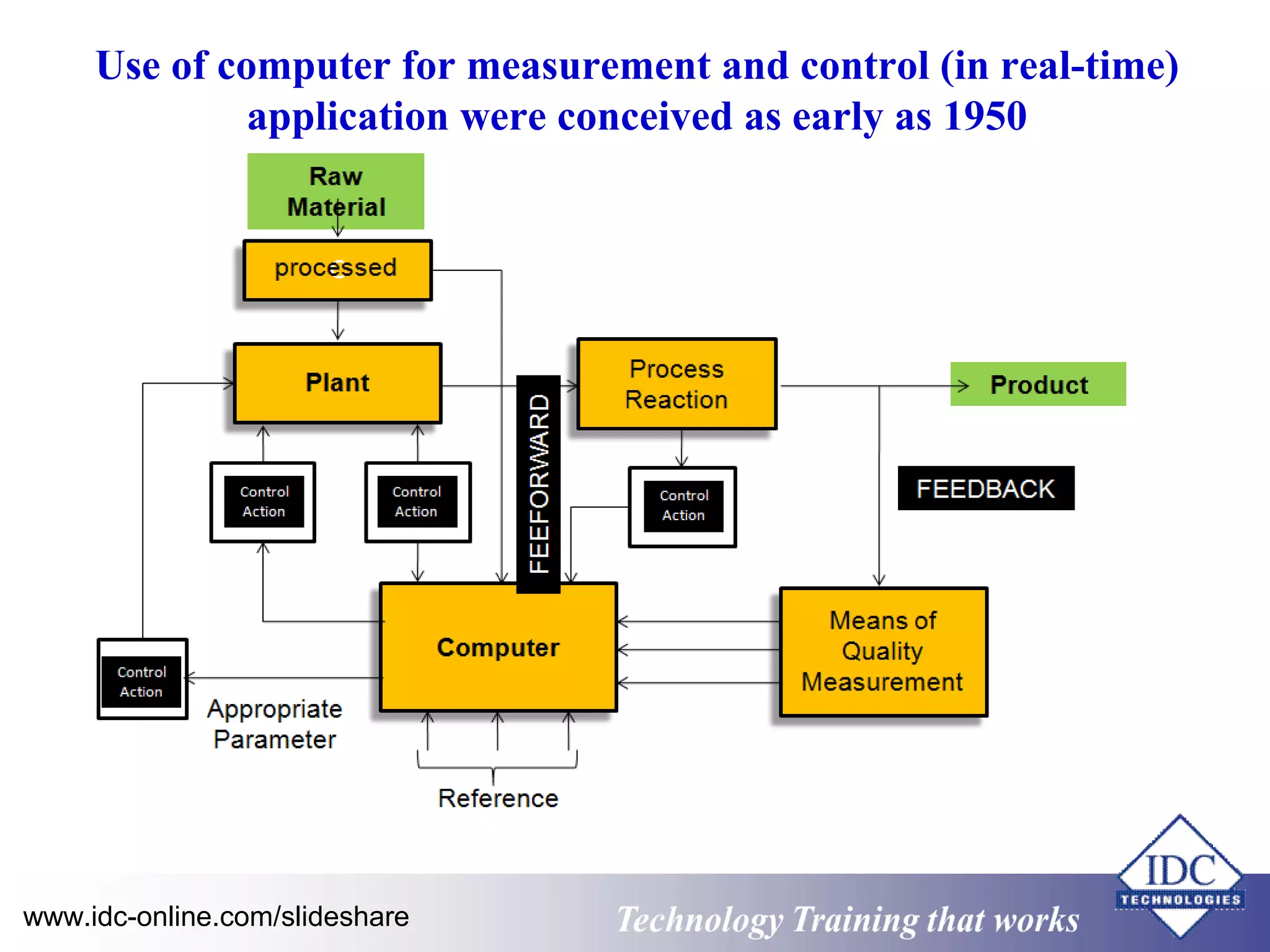
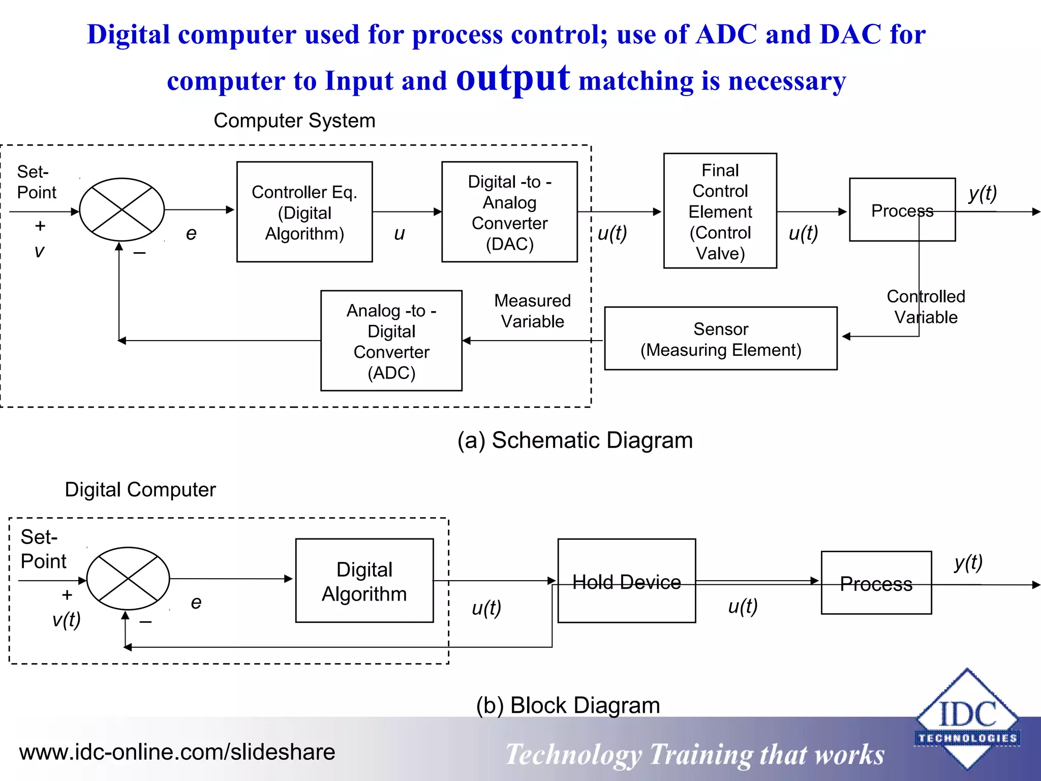
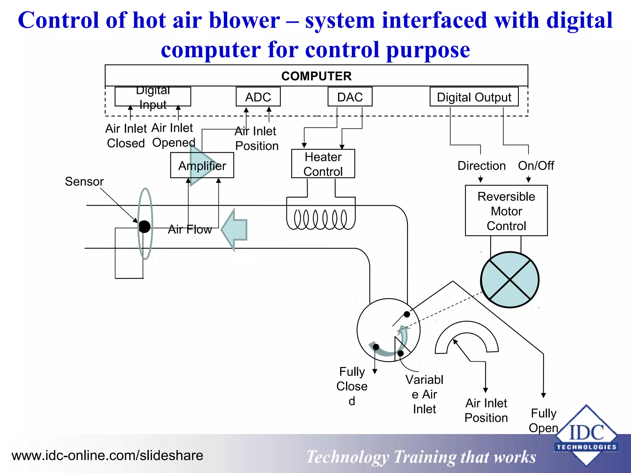
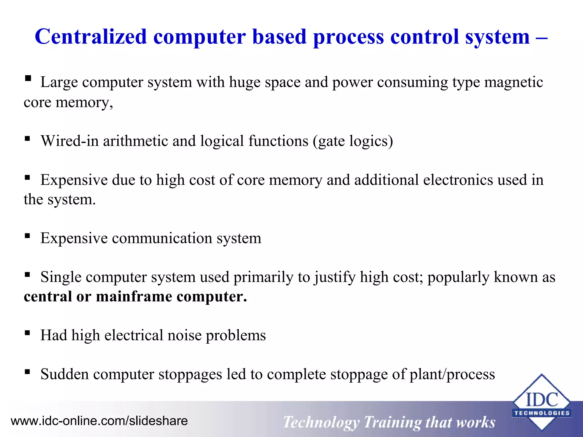


The document provides an overview of practical distributed control systems (DCS) for engineers and technicians, focusing on computer-based measurement and control systems, their components, architecture, and human-machine interfaces. It discusses the applications of digital computers in process control, both passive and active, as well as the hardware requirements for real-time control. Additionally, it covers interfacing computers with various process parameters and the role of multiplexing and modems in communication within these systems.