The document discusses processor logic design and register transfer logic. It describes registers, their functions, and how data is transferred between registers. There are four categories of microoperations - interregister transfer, arithmetic, logic, and shift. Interregister transfer moves data between registers without changing it. Arithmetic operations perform math on register data. Logic operations perform AND, OR, etc on register bit values. Shift operations serially move data within a register. The document also discusses conditional control statements that allow different microoperations to be selected based on register values.
Introduction to Module-V on Processor Logic Design covering the contents like Register Transfer Logic including Arithmetic, Logic, Shift Microoperations, and Conditional Control Statements.
Overview of registers as binary storage, their data movement and processing functions in digital systems, and the hierarchical design approach in large digital systems.
Description of microoperations and their types: interregister, arithmetic, logic, and shift, specifying how they affect data in registers. Introduction to RTL as symbolic notation for microoperations, explaining transfer operations and control functions within registers.
Details of control functions in data transfer processes in registers, including conditional transfers based on specific conditions.
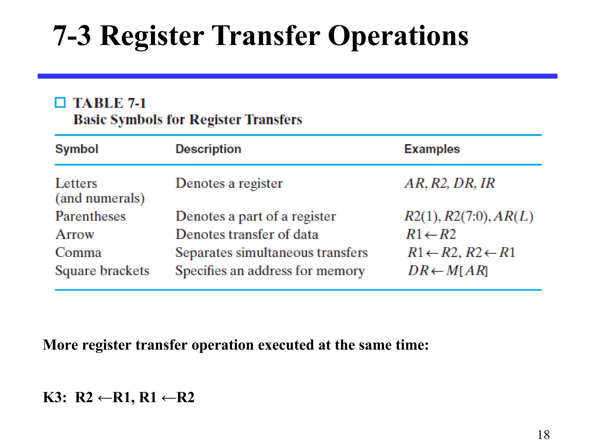
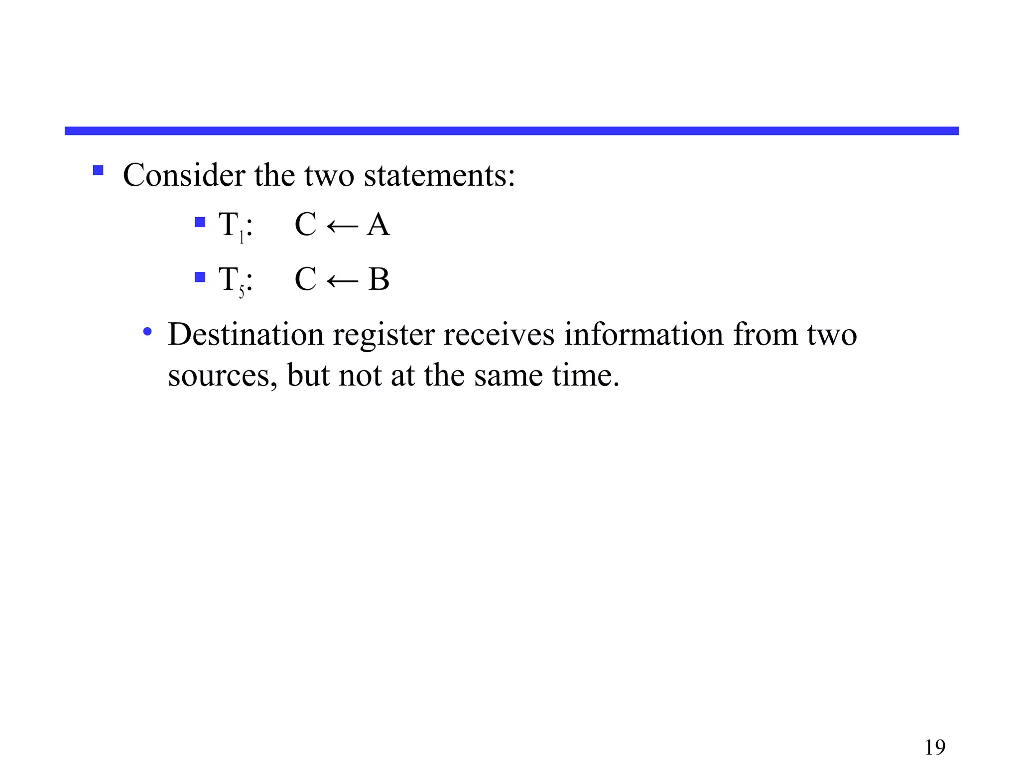
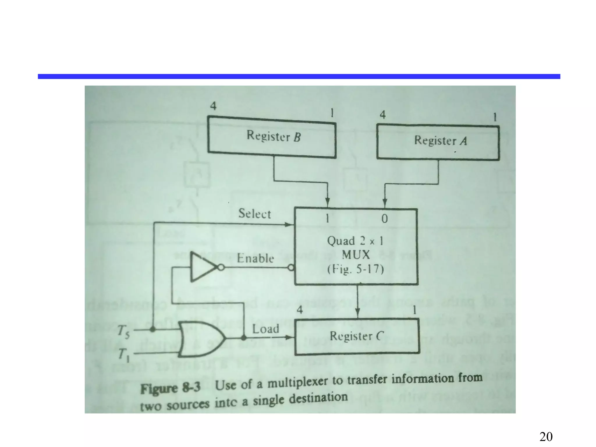
Execution of multiple register transfer operations simultaneously and how registers can receive information from different sources.
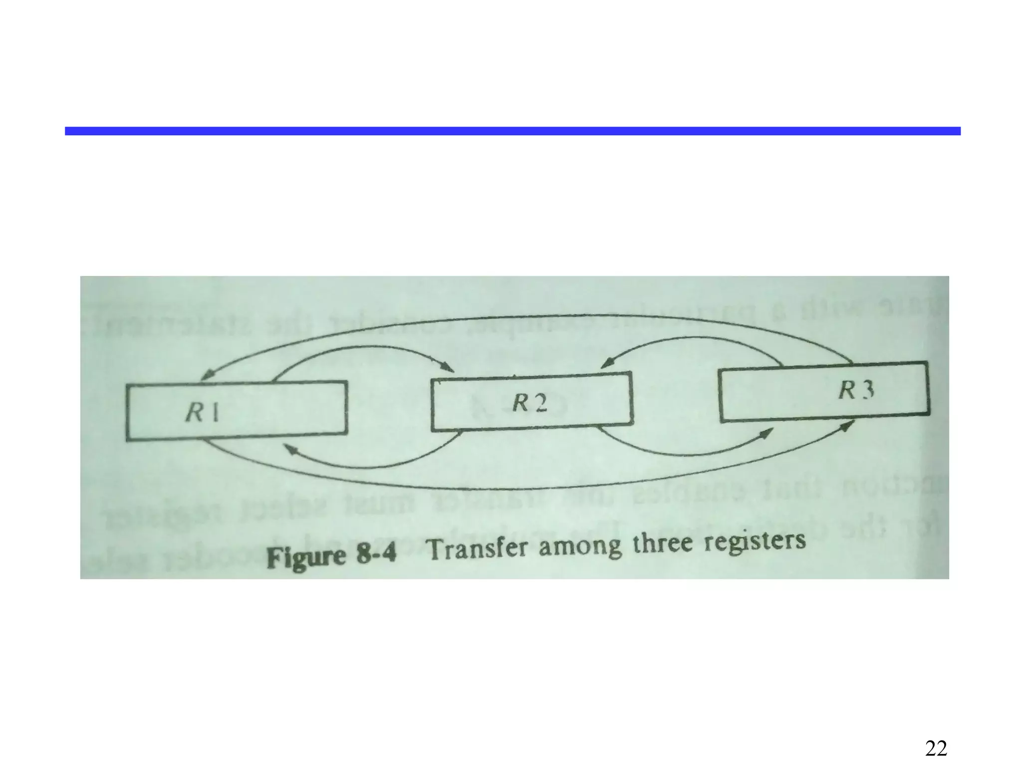
Functionality of common bus systems for transferring data between registers, along with memory read/write operations using specific address formatting.
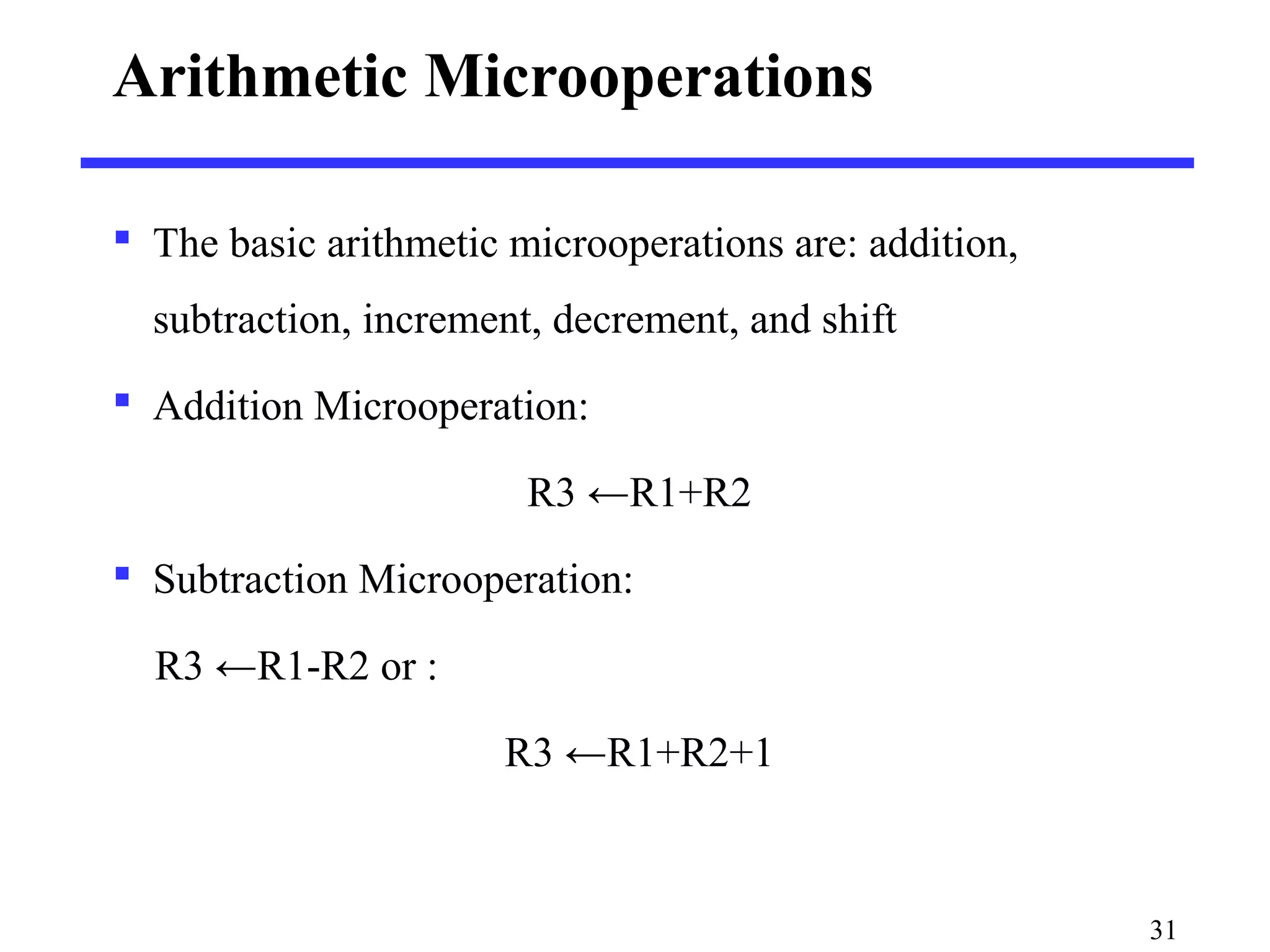
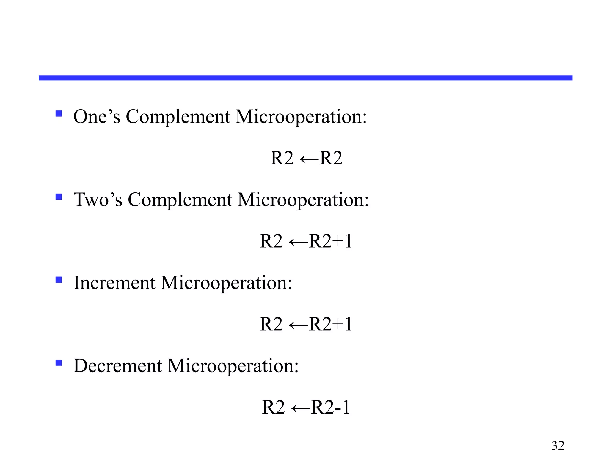
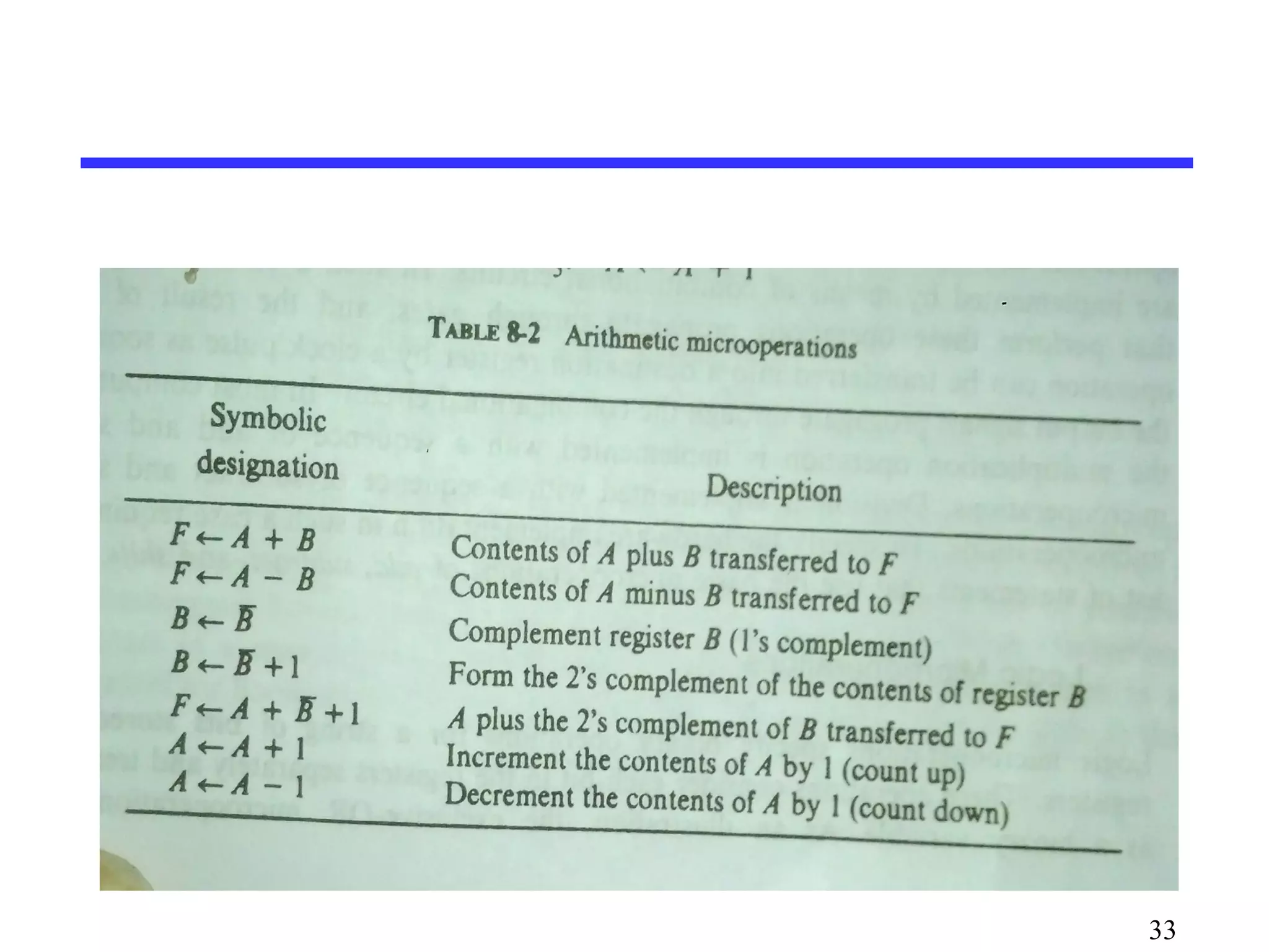
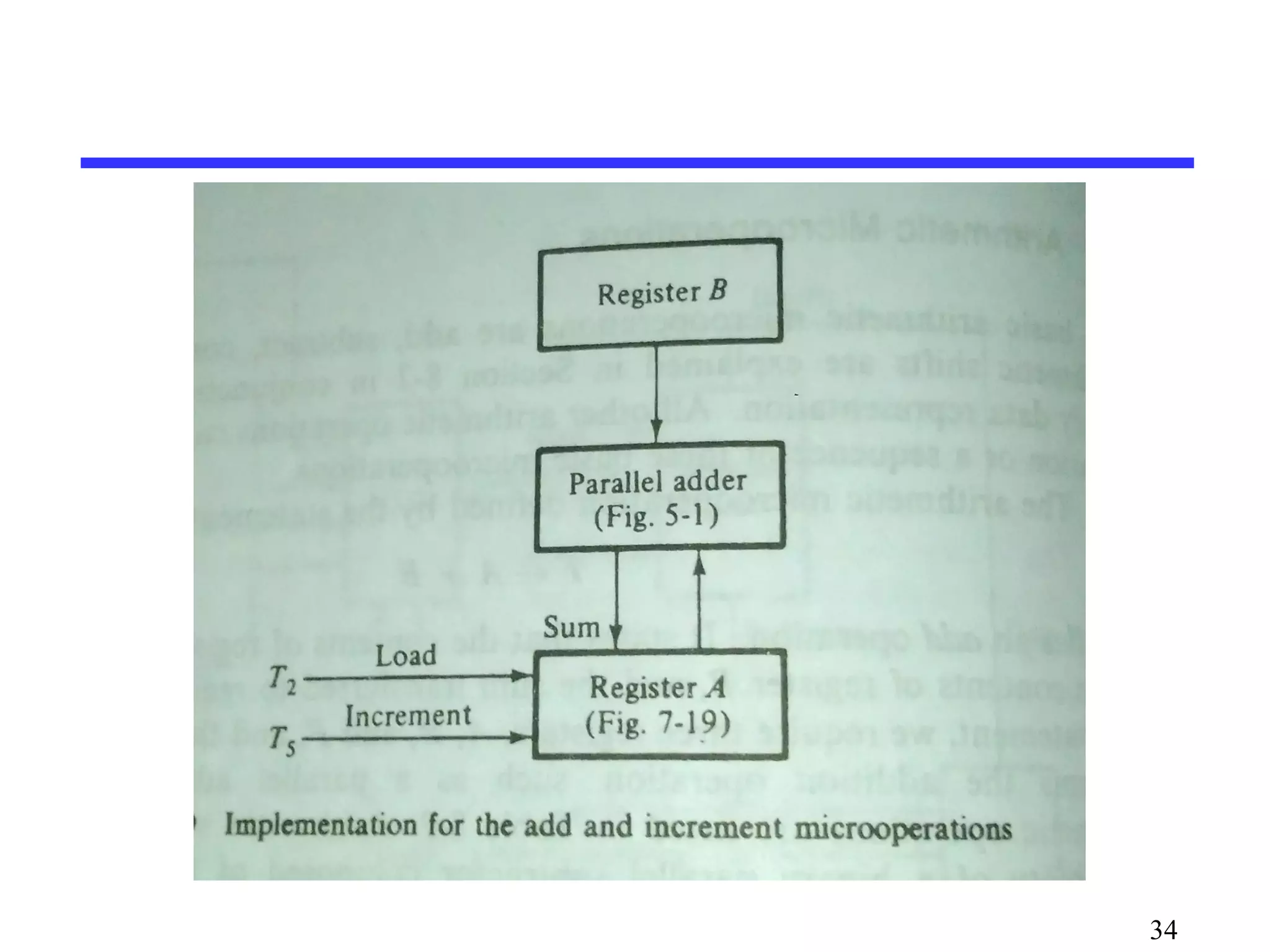
Explanation of basic arithmetic operations such as addition, subtraction, increment, and decrement performed on registers.
Introduction to logic microoperations executing binary operations like AND, OR, and exclusive-OR on individual bits in registers.
Detailed overview of shift microoperations, types of shifts (logical, circular, arithmetic), and their usage in data transfer.
Definition and examples of conditional control statements in processor logic design, illustrating the execution of microoperations based on conditions.
Contents
• RegisterTransfer Logic
Inter Register Transfer
Arithmetic Microoperations
Logic Microoperations
Shift Microoperations
• Conditional Control Statements
2
3.
3
Registers
Register
• acollection of binary storage elements
• included a set of flip-flop
• n-bit register store n-bit binary information
Frequently used to perform simple data
storage and data movement and processing
operations
5
Register transfer
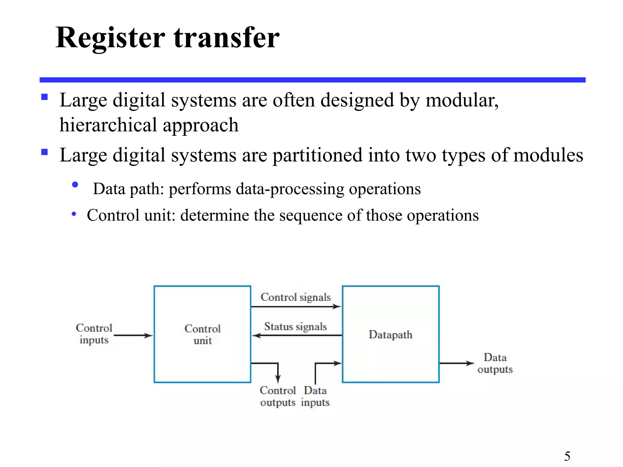
Largedigital systems are often designed by modular,
hierarchical approach
Large digital systems are partitioned into two types of modules
• Data path: performs data-processing operations
• Control unit: determine the sequence of those operations
6.
6
Register transfer
Theregisters are assumed to be basic components of the
digital system
Register transfer operation: movement on the data stored
in register and the processing performed on the data
The basic components for describing a digital system in
register transfer logic is:
• The set of registers in digital systems and their
functions.
• The operations performed on the data
• Control on the sequence of operations
7.
Register transfer Operations
Microoperations: operations executed on data stored in one
or more registers.
For any function of the computer, a sequence of
micro operations is used to describe it
The result of the operation may be:
• replace the previous binary information of a register or
• transferred to another register
7
8.
Register Transfer Language
Register Transfer Language (RTL) : a symbolic notation to
describe the microoperation transfers among registers
Next steps:
• Define symbols for various types of microoperations,
• Describe the hardware that implements these
microoperations
A statement in a register transfer language consists of a
control function and a list of micro operations.
8
9.
The typeof microoperations in digital systems can be
classified into four categories:
• Interregister –transfer microoperations do not change the
information content when the binary information moves from one
register to another.
• Arithmetic micro operations perform arithmetic on numbers stored
in registers.
• Logic microoperations perform operations such as AND and OR on
individual pairs of bits stored in registers.
• Shift microopeartions specify operations for shift registers.
9
10.
10
InterRegister Transfer
Computerregisters are designated by capital letters
(sometimes followed by numerals) to denote the function
of the register
R1: processor register
MAR: Memory Address Register (holds an address
for a memory unit)
PC: Program Counter
IR: Instruction Register
SR: Status Register
11.
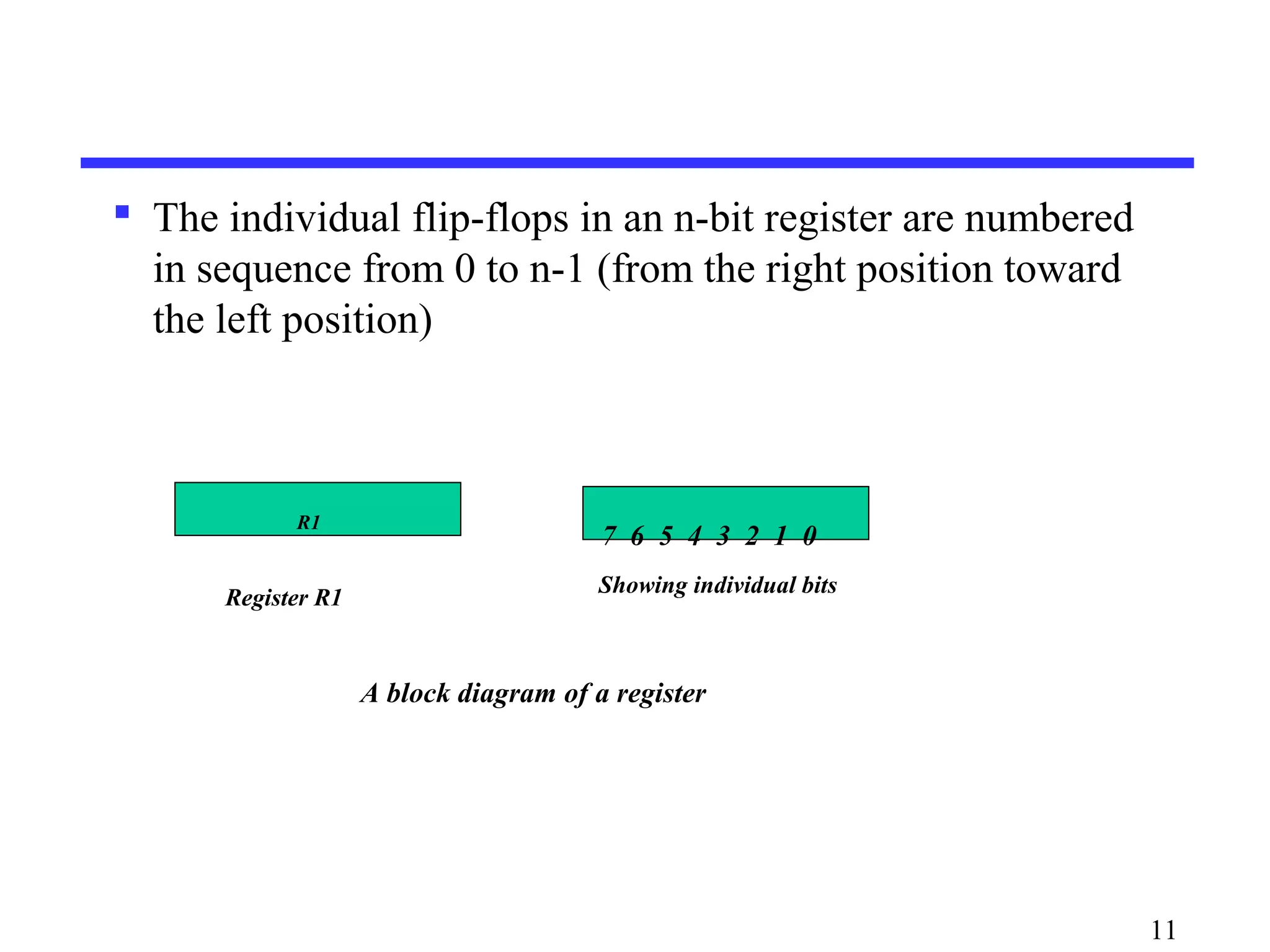
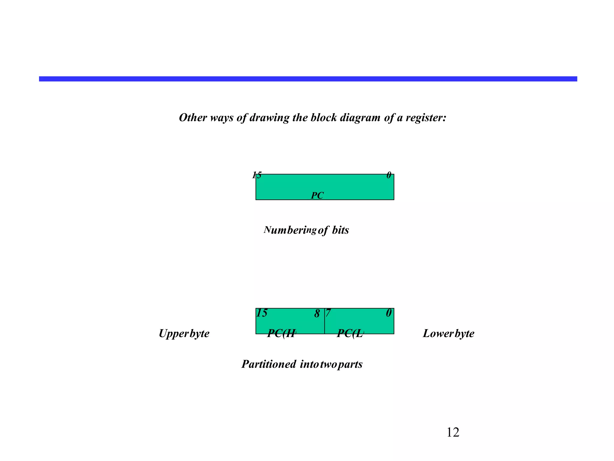
The individualflip-flops in an n-bit register are numbered
in sequence from 0 to n-1 (from the right position toward
the left position)
11
R1
Register R1
7 6 5 4 3 2 1 0
Showing individual bits
A block diagram of a register
13
Information transferfrom one register to another is described
by a replacement operator: R2 ← R1
This statement denotes a transfer of the content of register R1
into register R2
The transfer happens in one clock cycle
The content of the R1 (source) does not change
The content of the R2 (destination) will be lost and replaced by
the new data transferred from R1
We are assuming that the circuits are available from the outputs
of the source register to the inputs of the destination register,
and that the destination register has a parallel load capability
14.
14
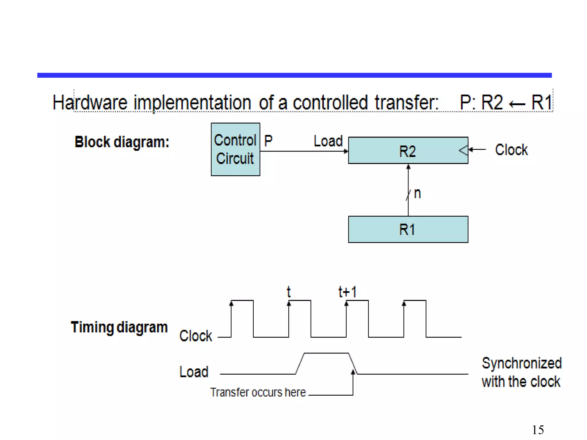
The conditionwhich determines when the transfer is to occur
is called a control function.
Conditional transfer occurs only under a control condition
Representation of a (conditional) transfer
P: R2 ← R1
A binary condition (P equals to 0 or 1) determines when the
transfer occurs
The content of R1 is transferred into R2 only if P is 1
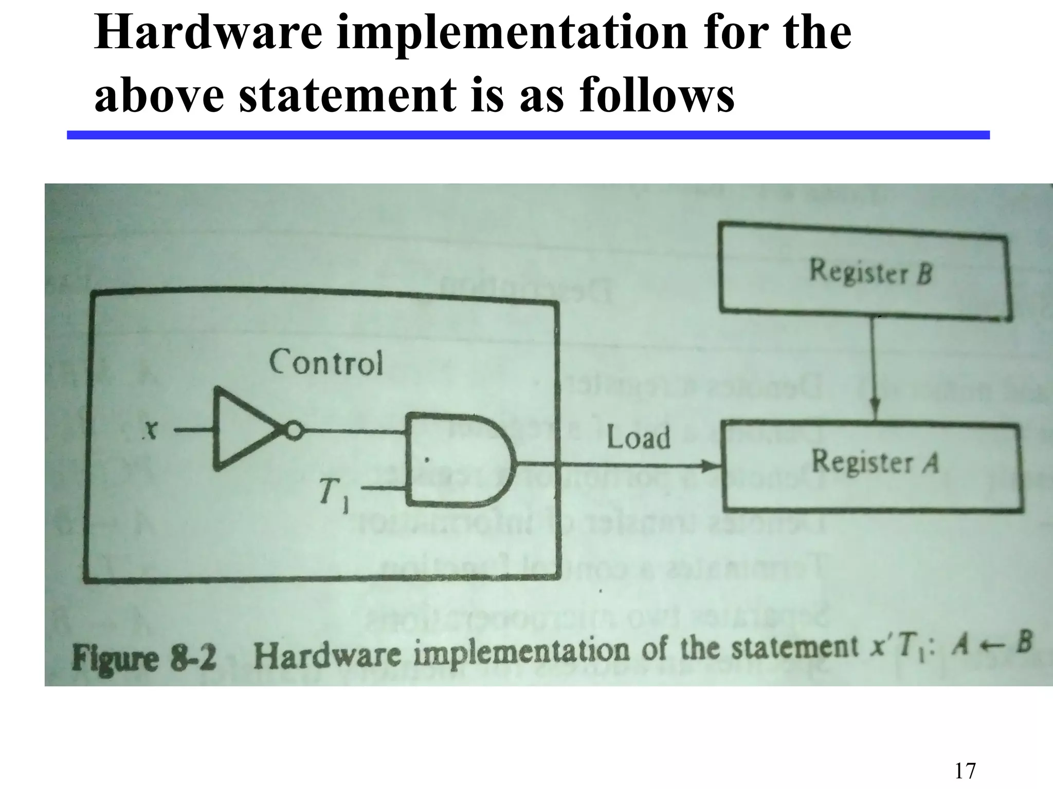
The controlfunction is included with the statement is as
follows:
x’T1: A ← B
The control function is terminated with a colon.
It shows that the transfer operation be executed by the
hardware only when the Boolean function x’T1 = 1
• i.e,when variable x=0 and timing variable T1 = 1
16
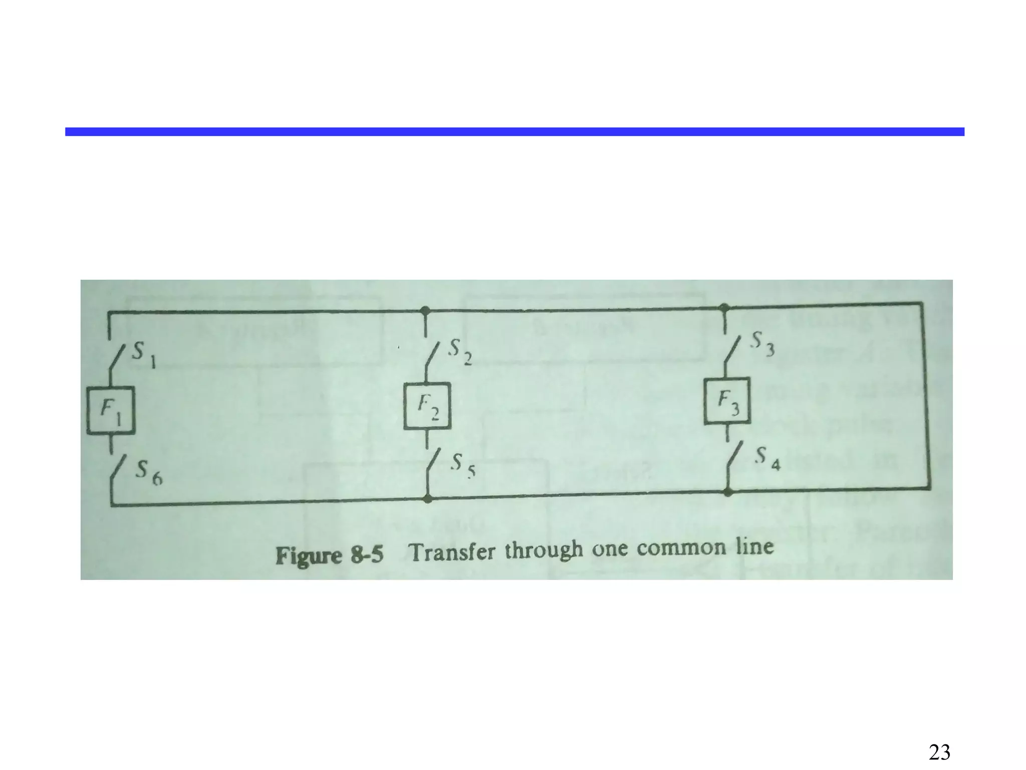
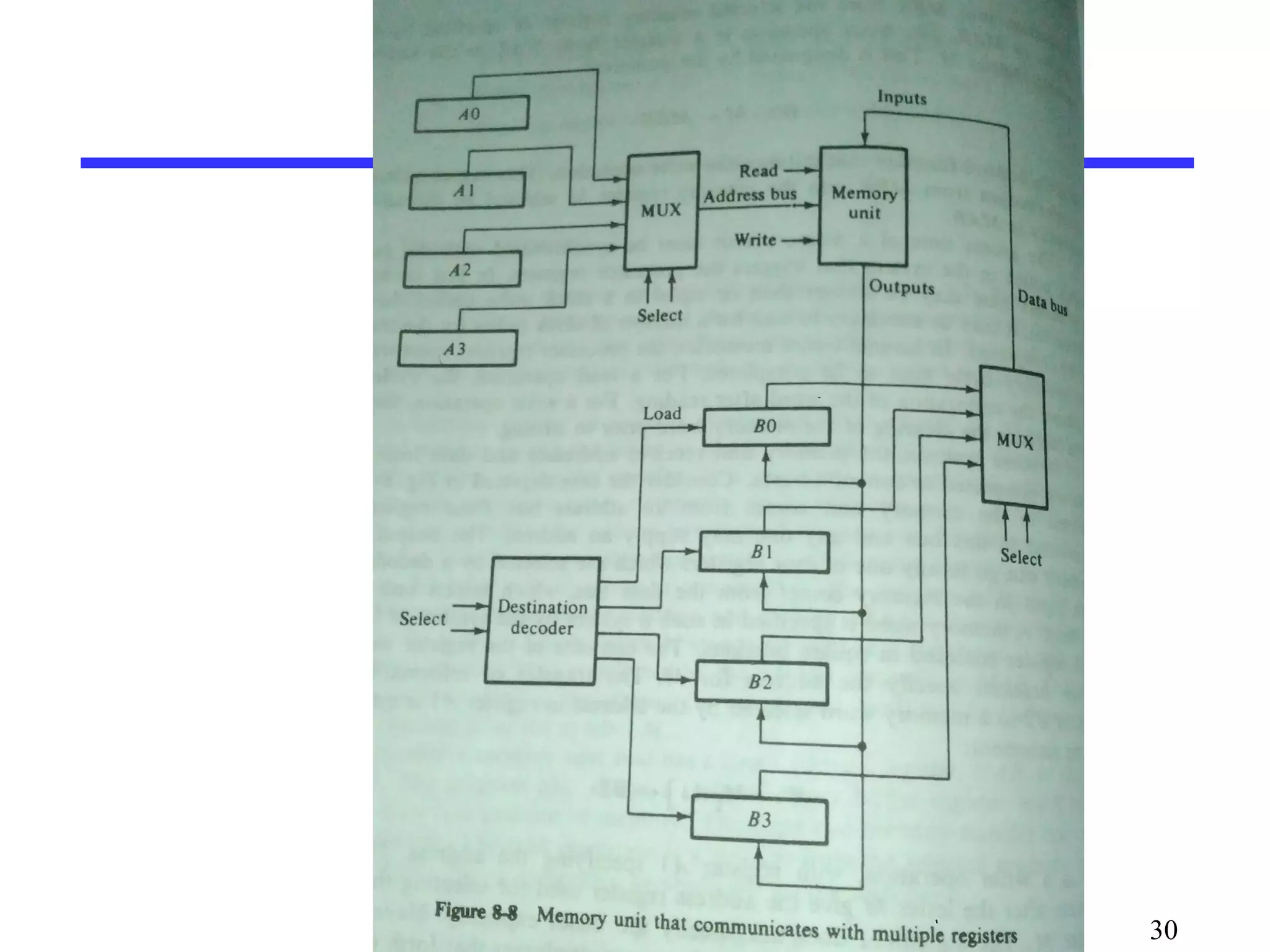
Bus and MemoryTransfers
Paths must be provided to transfer information from one register
to another
A Common Bus System is a scheme for transferring information
between registers in a multiple-register configuration
A bus: set of common lines, one for each bit of a register,
through which binary information is transferred one at a time
Control signals determine which register is selected by the bus
during each particular register transfer
21
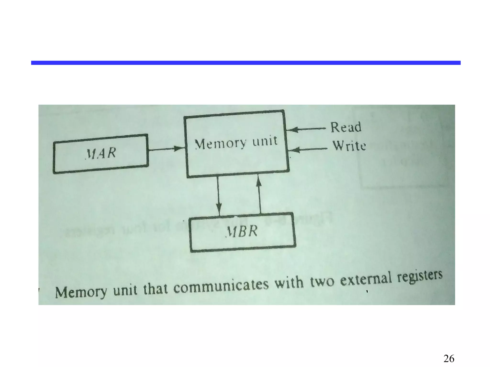
Memory Transfer
Memoryread : Transfer from memory
Memory write : Transfer to memory
Data being read or wrote is called a memory word (called
M)
It is necessary to specify the address of M when writing
/reading memory
This is done by enclosing the address in square brackets
following the letter M
Example: M[0016] : the memory contents at address
0x0016
25
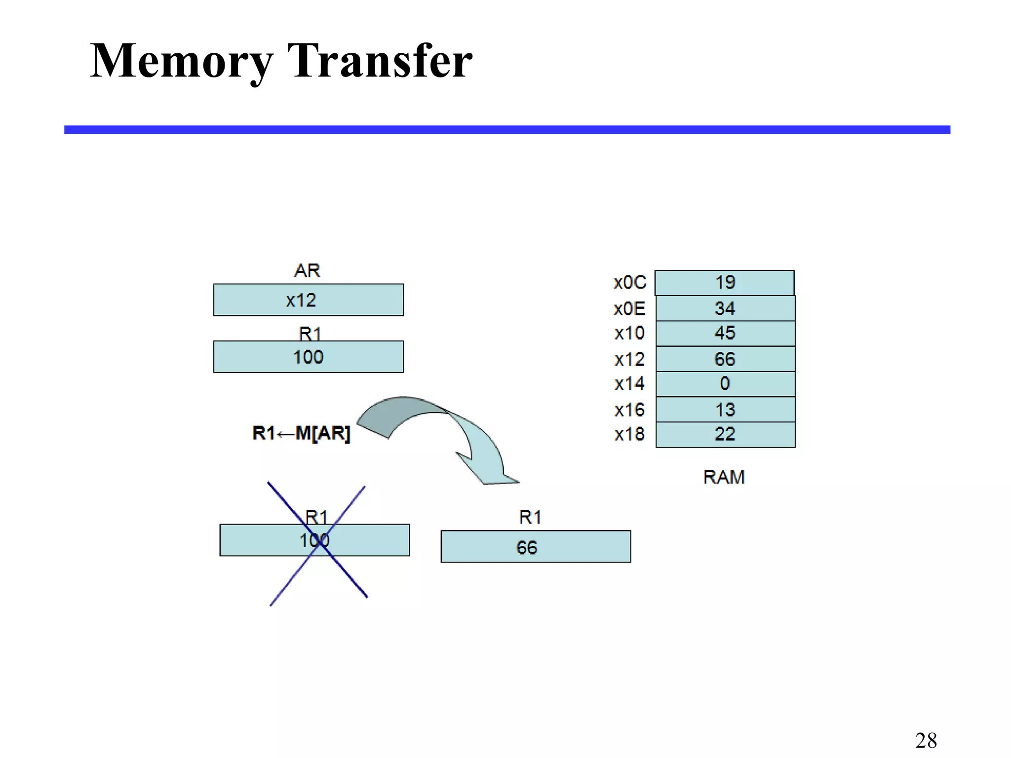
Assume thatthe address of a memory unit is
stored in a register called the Address
Register AR
Lets represent a Data Register with DR,
then:
Read: DR ← M[AR]
Write: M[AR] ← DR
27
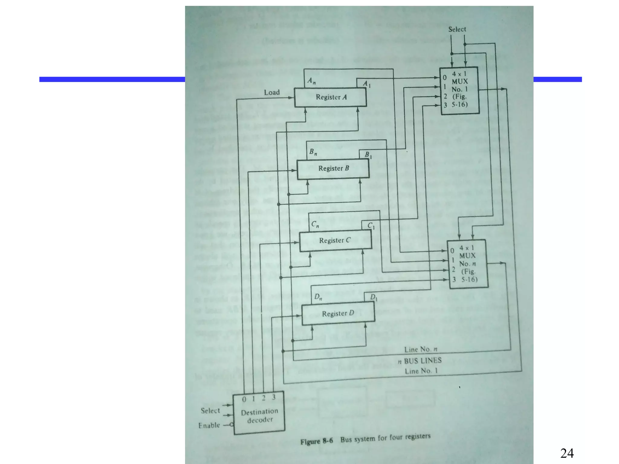
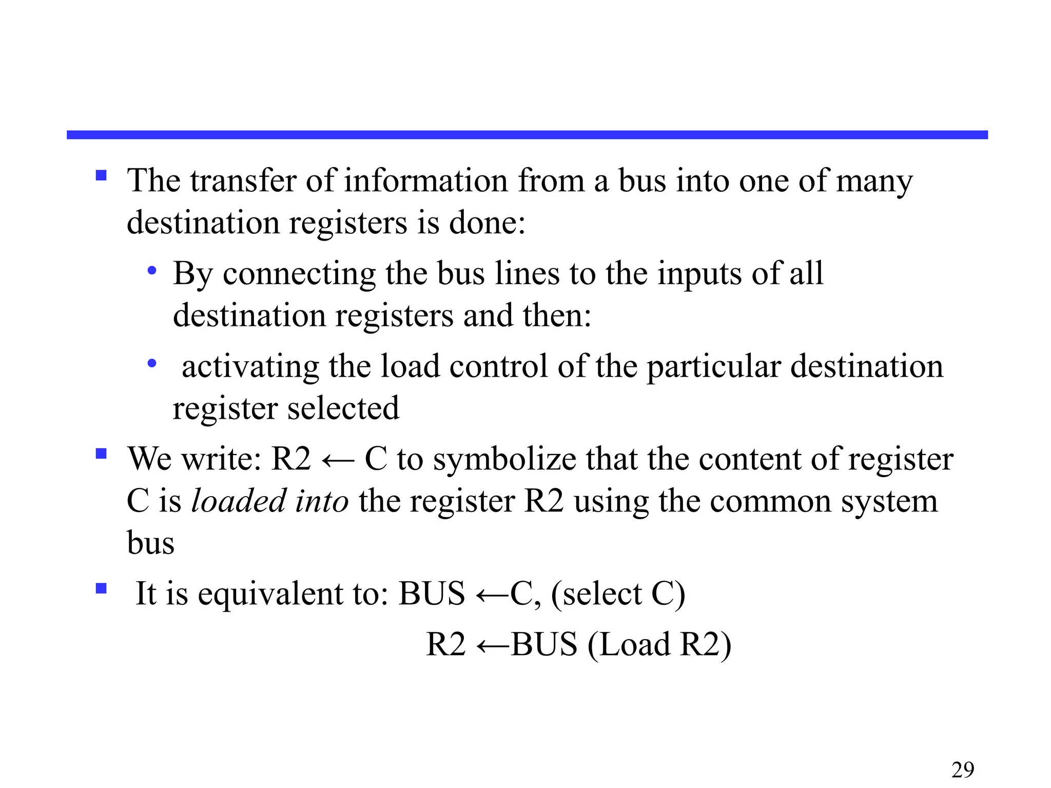
The transferof information from a bus into one of many
destination registers is done:
• By connecting the bus lines to the inputs of all
destination registers and then:
• activating the load control of the particular destination
register selected
We write: R2 ← C to symbolize that the content of register
C is loaded into the register R2 using the common system
bus
It is equivalent to: BUS ←C, (select C)
R2 ←BUS (Load R2)
29
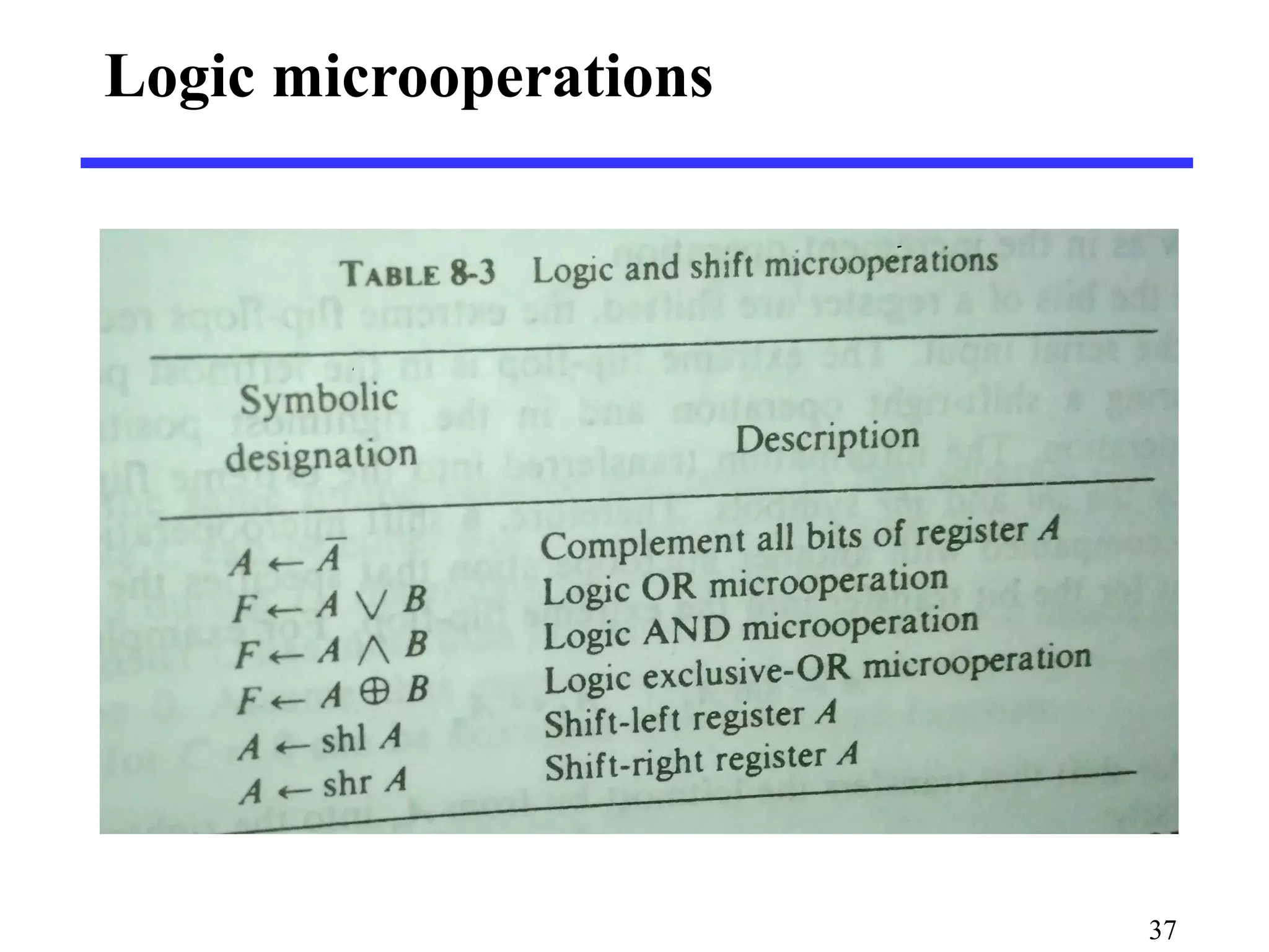
Logic microoperations
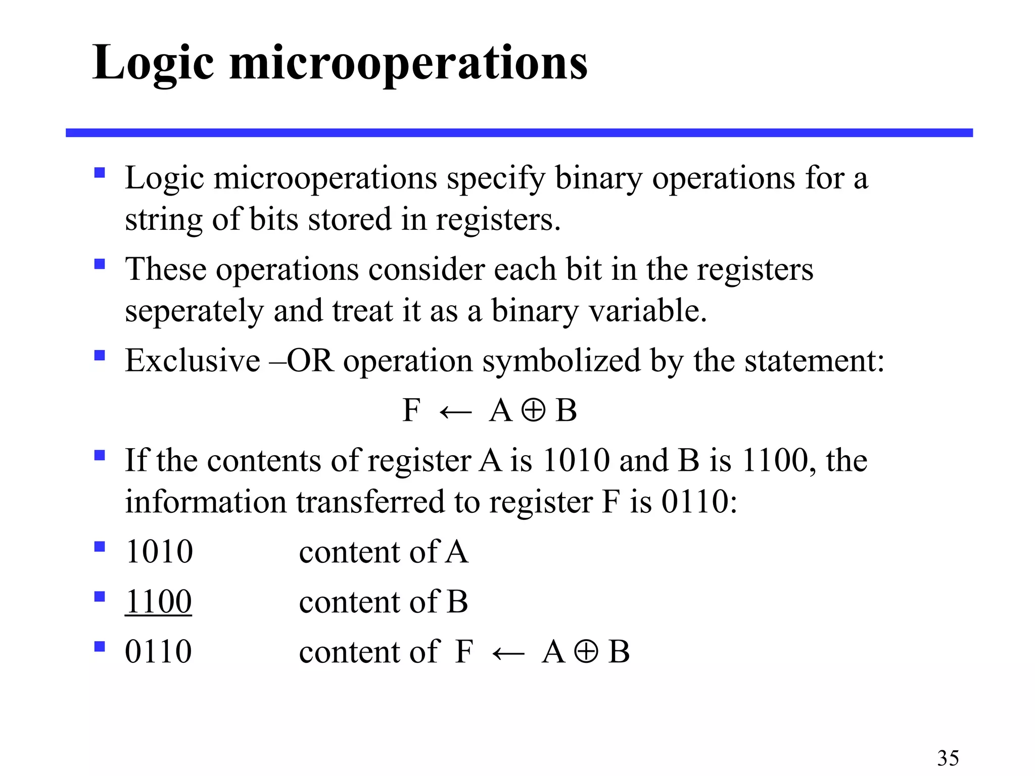
Logicmicrooperations specify binary operations for a
string of bits stored in registers.
These operations consider each bit in the registers
seperately and treat it as a binary variable.
Exclusive –OR operation symbolized by the statement:
F ← A ⊕ B
If the contents of register A is 1010 and B is 1100, the
information transferred to register F is 0110:
1010 content of A
1100 content of B
0110 content of F ← A ⊕ B
35
36.
16 differentpossible logic operations that
can be performed with two binary variables,
The symbol ∨ will be used to denote OR
microoperation and the symbol ∧ to denote
an AND microoperation.
Complement microoperation is the sameas
1’s complement and use a bar on top of the
letter that denotes the register.
36
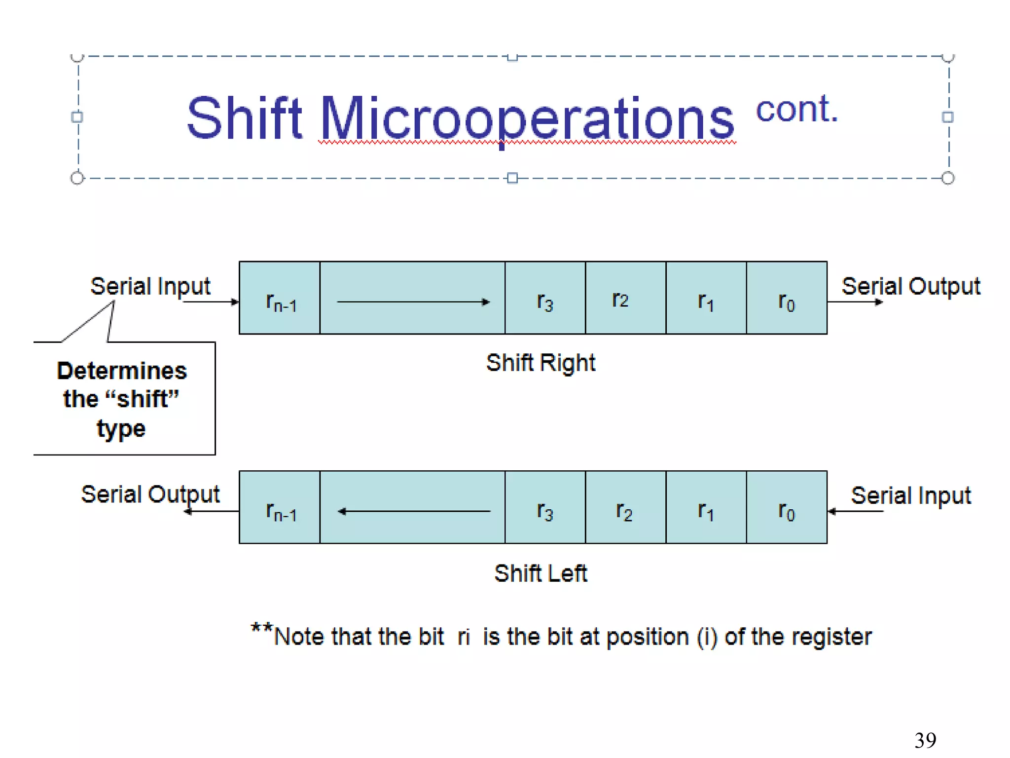
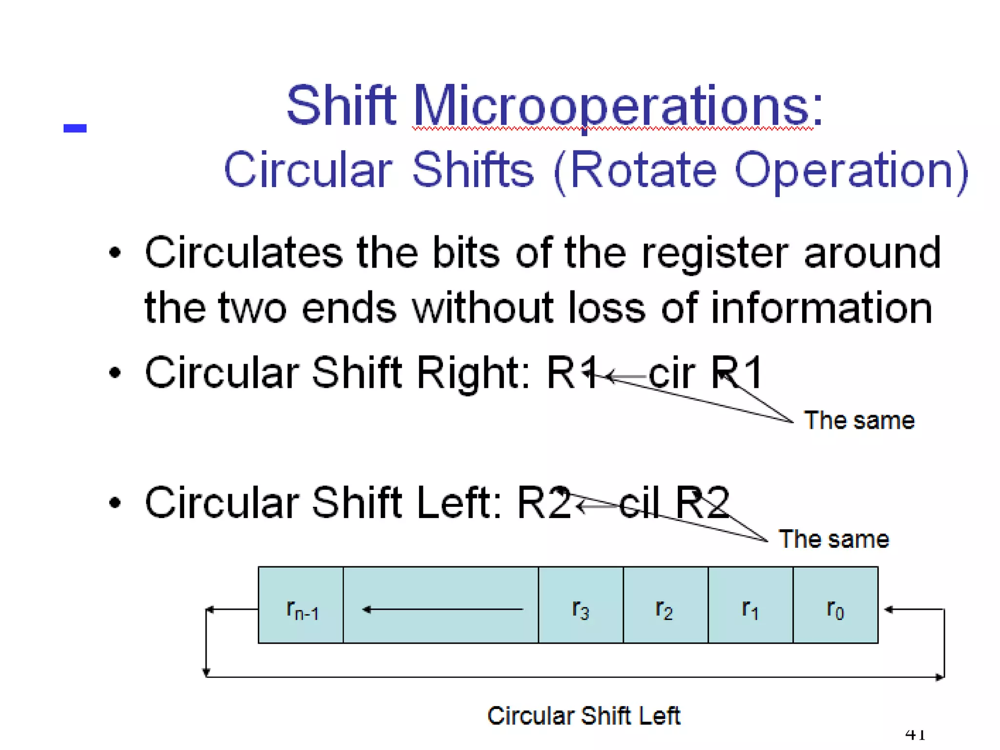
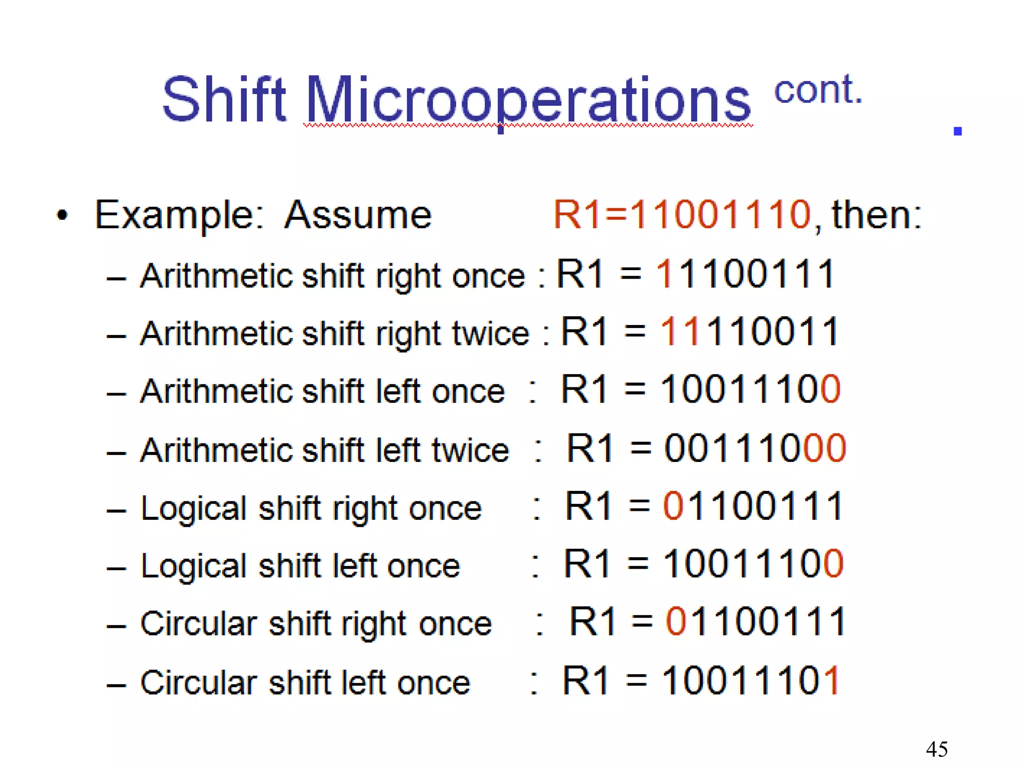
Shift Microoperations
Usedfor serial transfer of data
Also used in conjunction with arithmetic, logic, and other
data-processing operations
The contents of the register can be shifted to the left or to
the right
As being shifted, the first flip-flop receives its binary
information from the serial input
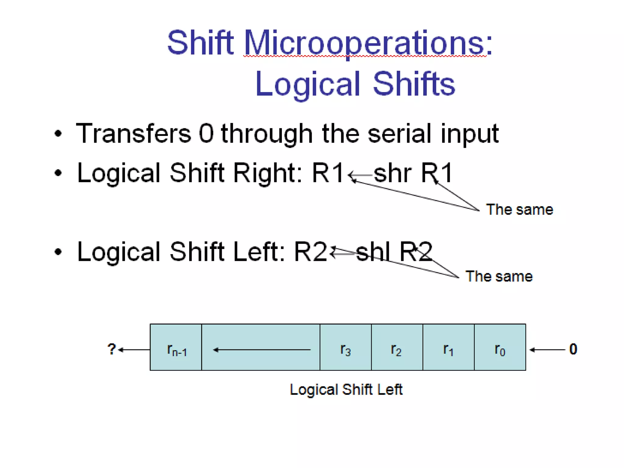
Three types of shift: Logical, Circular, and Arithmetic
38
CONDITIONAL CONTROL STATEMENTS
Conditional control statement is symbolized by an if-then –
else statement as follows:
P: If (condition) then [microoperation(s)] else
[microoperation(s)]
• It means that if the control condition stated within the
parentheses after the word if is true, then the
microoperation enclosed within the parentheses after
the word then is executed.
• If the condition is not true, the microoperation listed
after the word else is executed.
• In any case the control function P must occur for
anything to be done.
46
47.
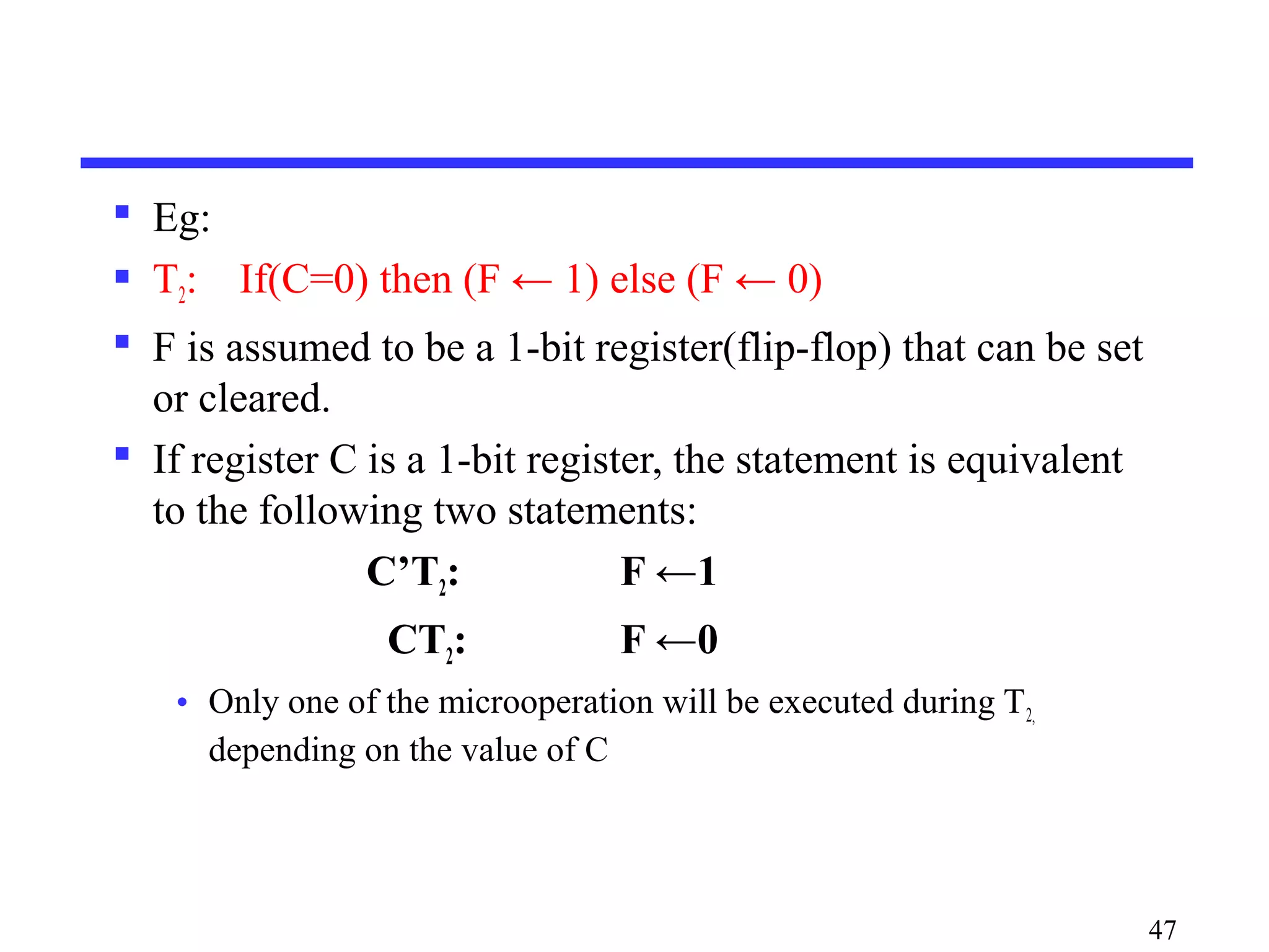
Eg:
T2:If(C=0) then (F ← 1) else (F ← 0)
F is assumed to be a 1-bit register(flip-flop) that can be set
or cleared.
If register C is a 1-bit register, the statement is equivalent
to the following two statements:
C’T2: F ←1
CT2: F ←0
• Only one of the microoperation will be executed during T2,
depending on the value of C
47
Editor's Notes
#5 States: 22 = 4
Input Combinations: 22 = 4
Output Combinations: 22 = 4
Y = A
A(t+1) = IN
Moore
States = 2n
Input Combinations = 2n
Output Combinations = 2n


![Memory Transfer
Memory read : Transfer from memory
Memory write : Transfer to memory
Data being read or wrote is called a memory word (called
M)
It is necessary to specify the address of M when writing
/reading memory
This is done by enclosing the address in square brackets
following the letter M
Example: M[0016] : the memory contents at address
0x0016
25](https://image.slidesharecdn.com/module5-part1-170527041953/75/Module-5-part1-25-2048.jpg)
![ Assume that the address of a memory unit is
stored in a register called the Address
Register AR
Lets represent a Data Register with DR,
then:
Read: DR ← M[AR]
Write: M[AR] ← DR
27](https://image.slidesharecdn.com/module5-part1-170527041953/75/Module-5-part1-27-2048.jpg)
![CONDITIONAL CONTROL STATEMENTS
Conditional control statement is symbolized by an if-then –
else statement as follows:
P: If (condition) then [microoperation(s)] else
[microoperation(s)]
• It means that if the control condition stated within the
parentheses after the word if is true, then the
microoperation enclosed within the parentheses after
the word then is executed.
• If the condition is not true, the microoperation listed
after the word else is executed.
• In any case the control function P must occur for
anything to be done.
46](https://image.slidesharecdn.com/module5-part1-170527041953/75/Module-5-part1-46-2048.jpg)


![Memory Transfer
Memory read : Transfer from memory
Memory write : Transfer to memory
Data being read or wrote is called a memory word (called
M)
It is necessary to specify the address of M when writing
/reading memory
This is done by enclosing the address in square brackets
following the letter M
Example: M[0016] : the memory contents at address
0x0016
25](https://crownmelresort.com/image.slidesharecdn.com/module5-part1-170527041953/75/Module-5-part1-25-2048.jpg)

![ Assume that the address of a memory unit is
stored in a register called the Address
Register AR
Lets represent a Data Register with DR,
then:
Read: DR ← M[AR]
Write: M[AR] ← DR
27](https://crownmelresort.com/image.slidesharecdn.com/module5-part1-170527041953/75/Module-5-part1-27-2048.jpg)


![CONDITIONAL CONTROL STATEMENTS
Conditional control statement is symbolized by an if-then –
else statement as follows:
P: If (condition) then [microoperation(s)] else
[microoperation(s)]
• It means that if the control condition stated within the
parentheses after the word if is true, then the
microoperation enclosed within the parentheses after
the word then is executed.
• If the condition is not true, the microoperation listed
after the word else is executed.
• In any case the control function P must occur for
anything to be done.
46](https://crownmelresort.com/image.slidesharecdn.com/module5-part1-170527041953/75/Module-5-part1-46-2048.jpg)