Download to read offline
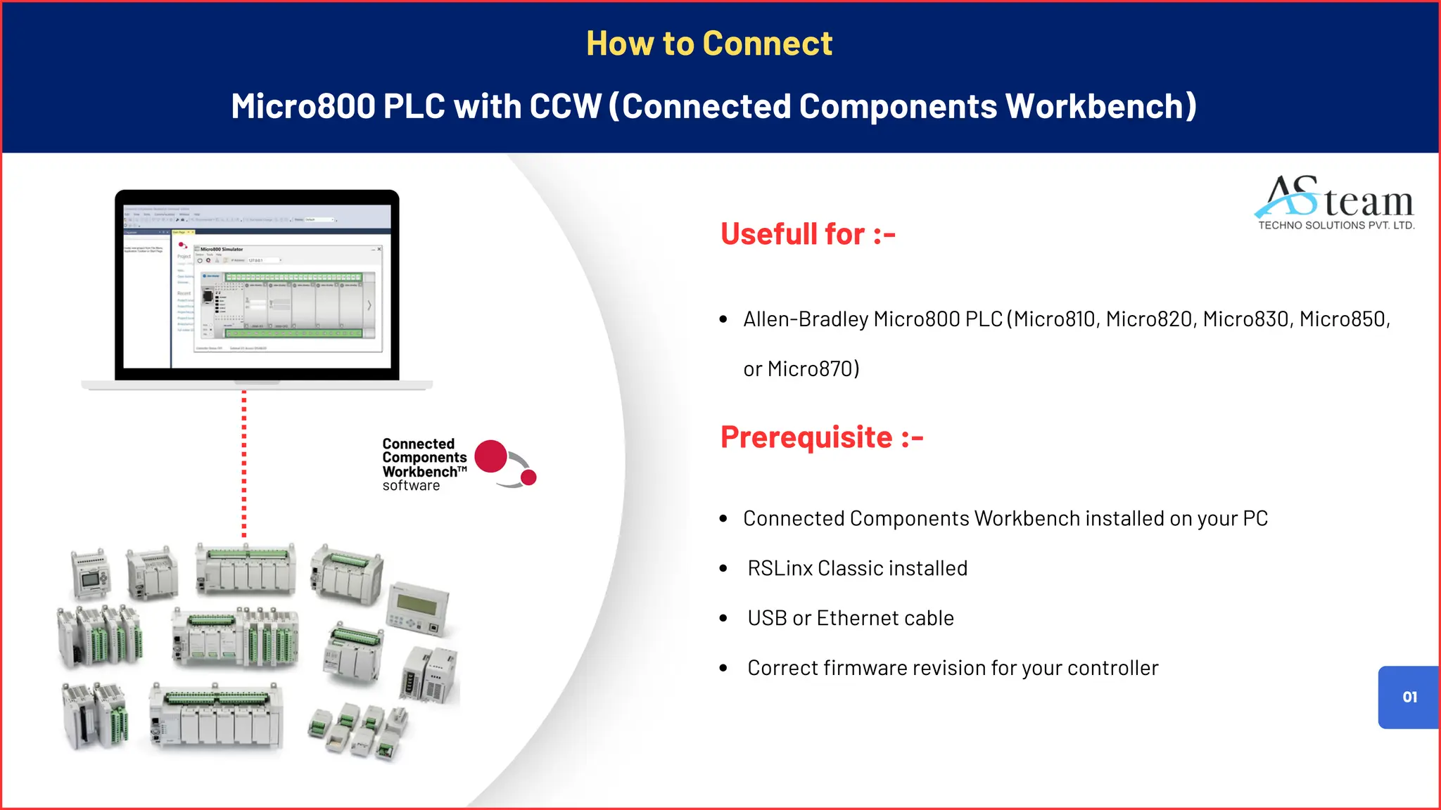
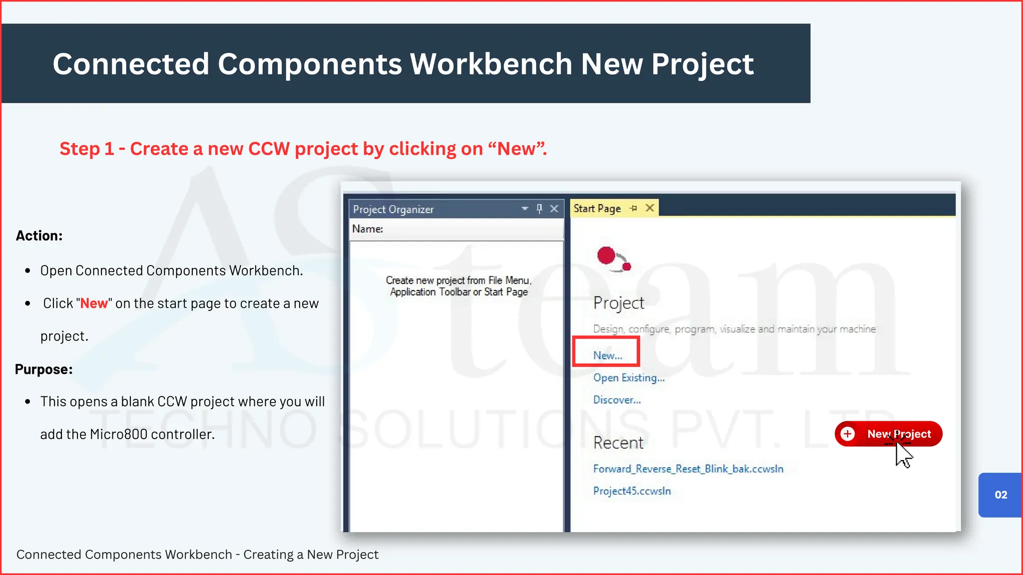
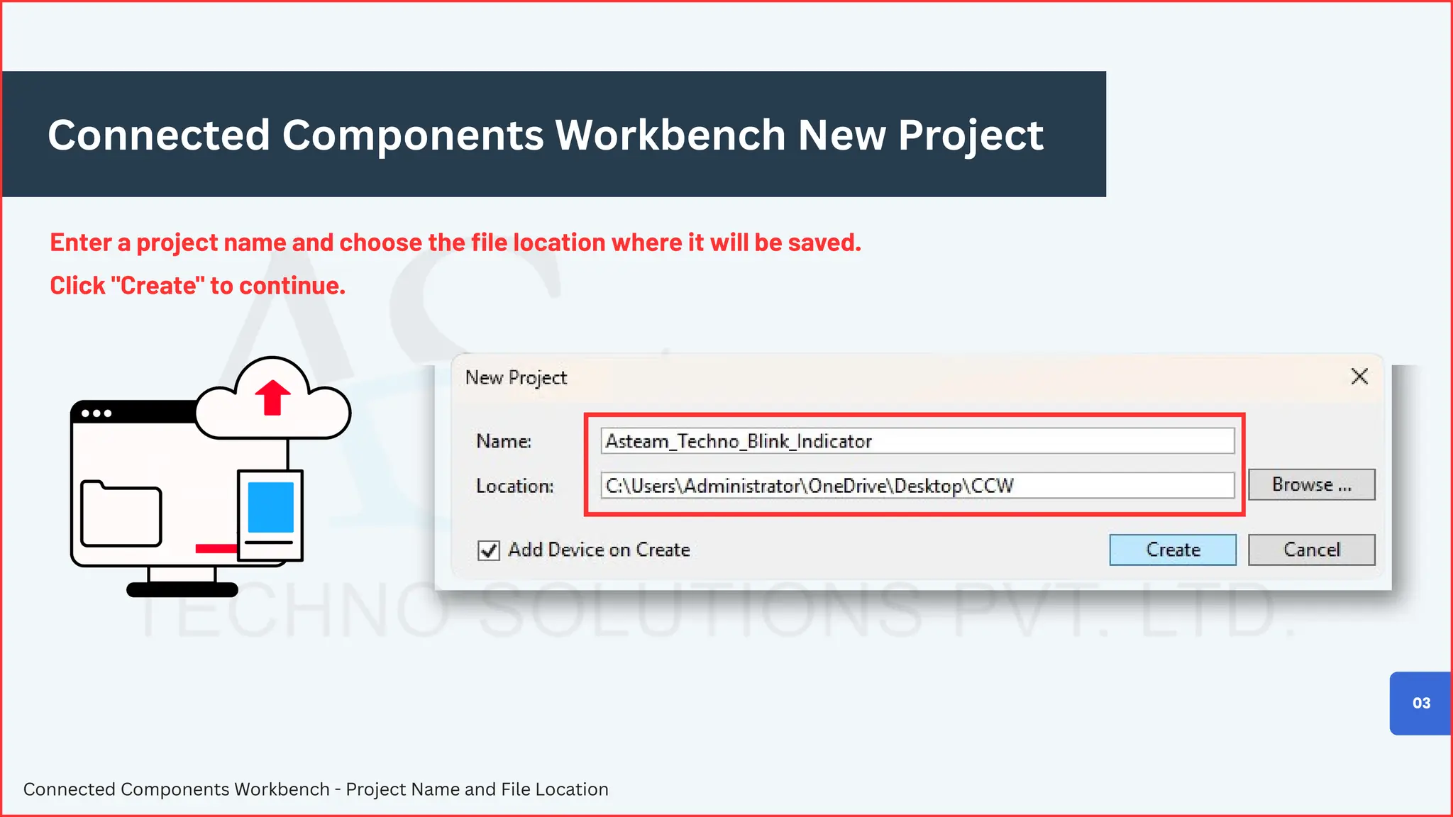
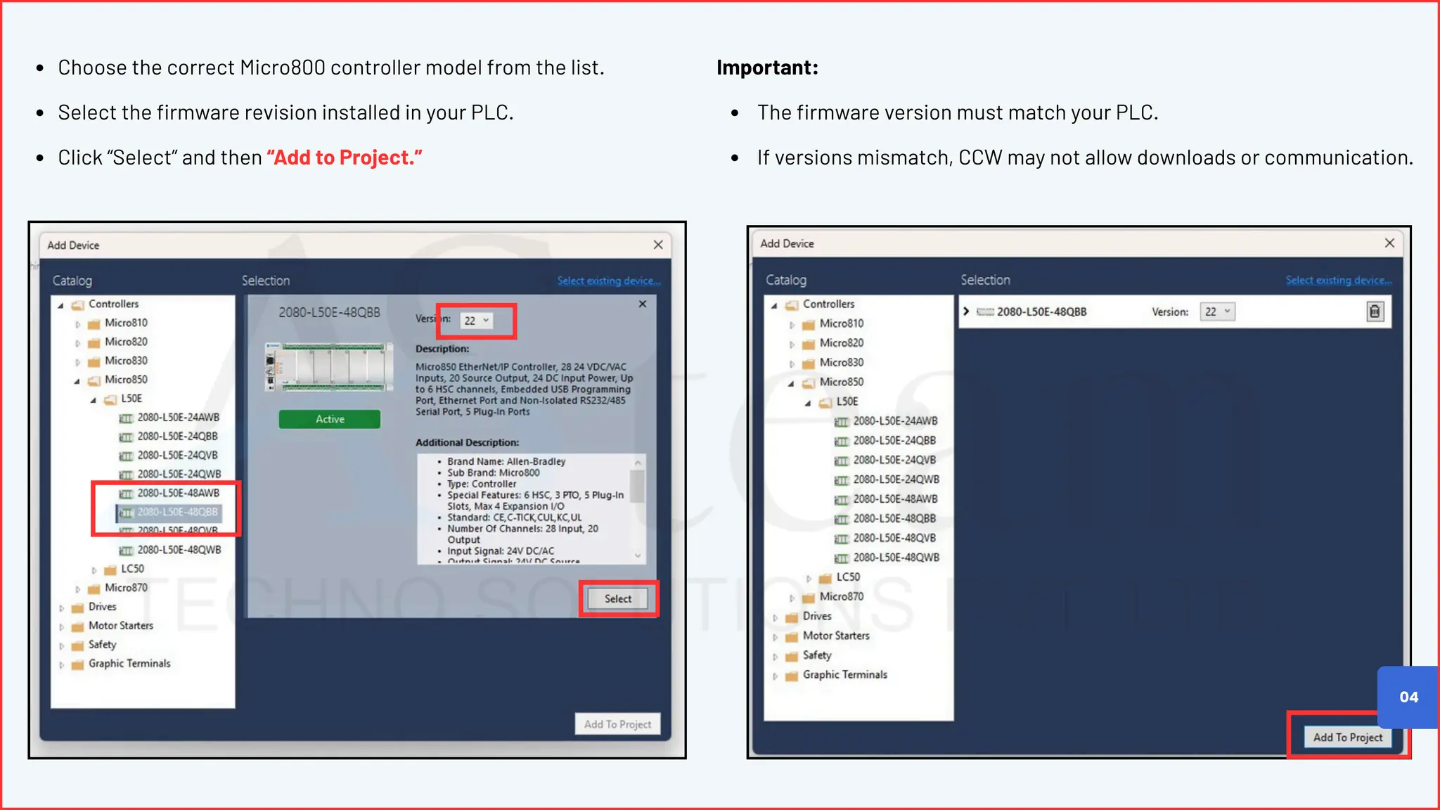
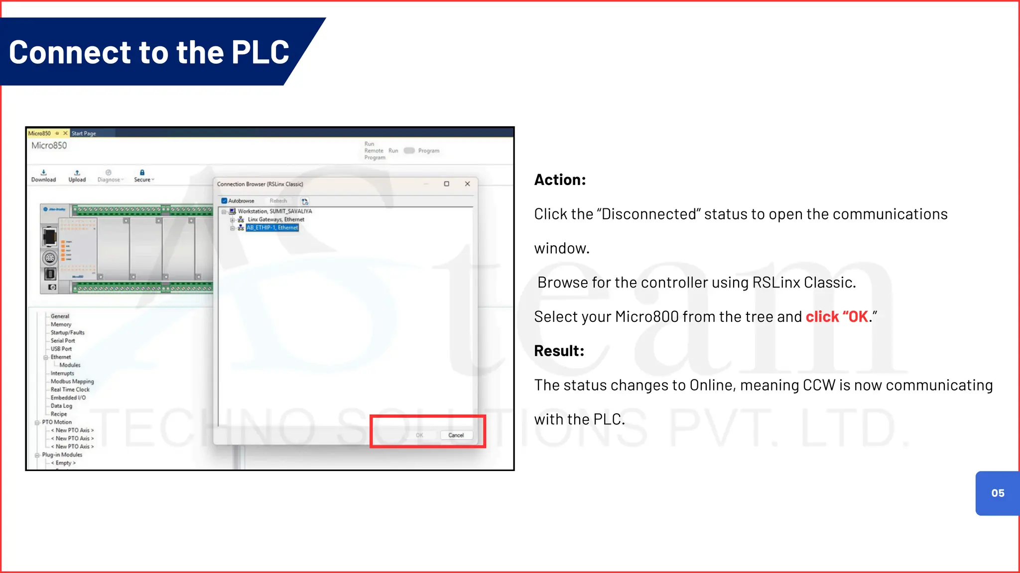
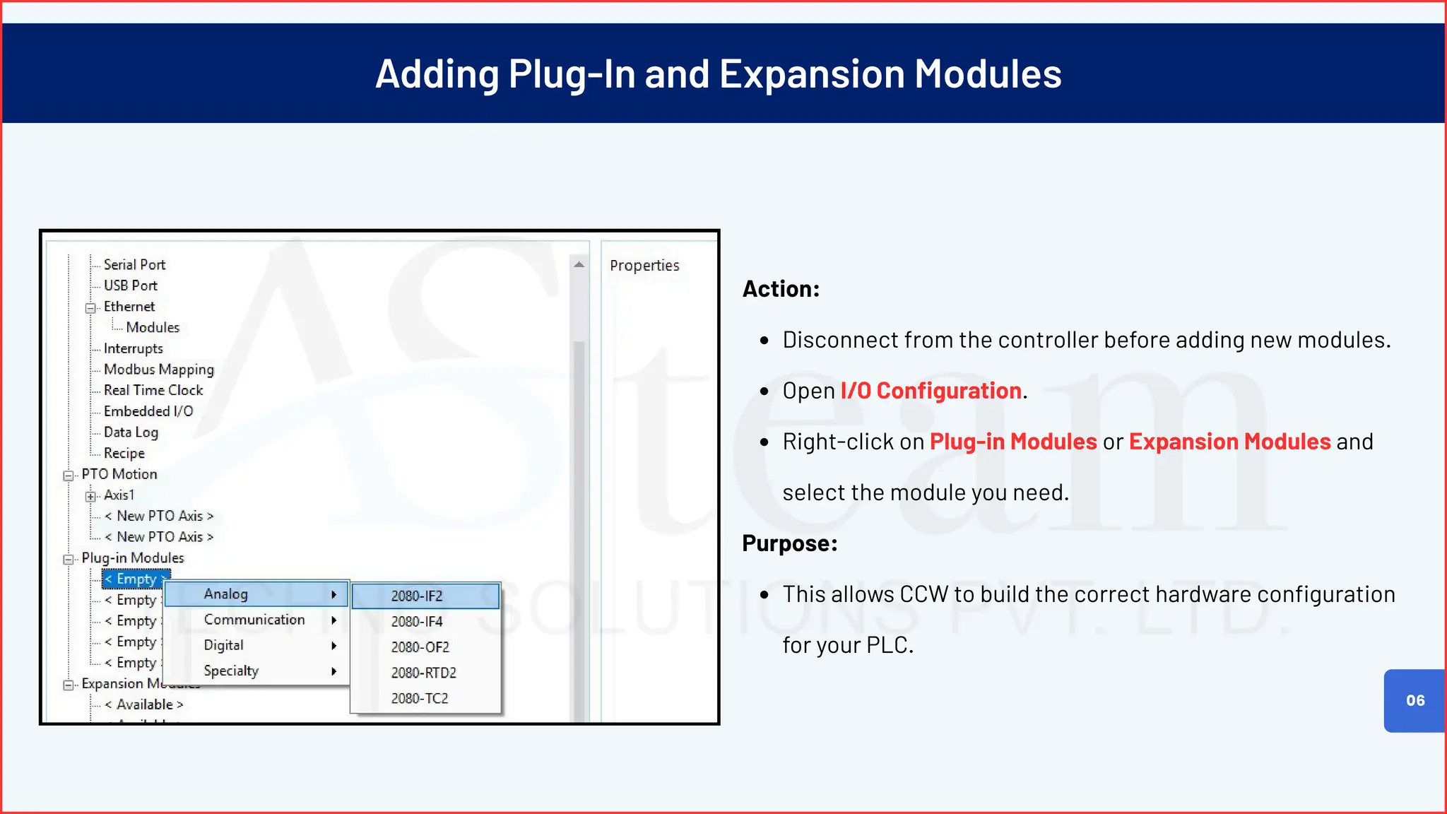
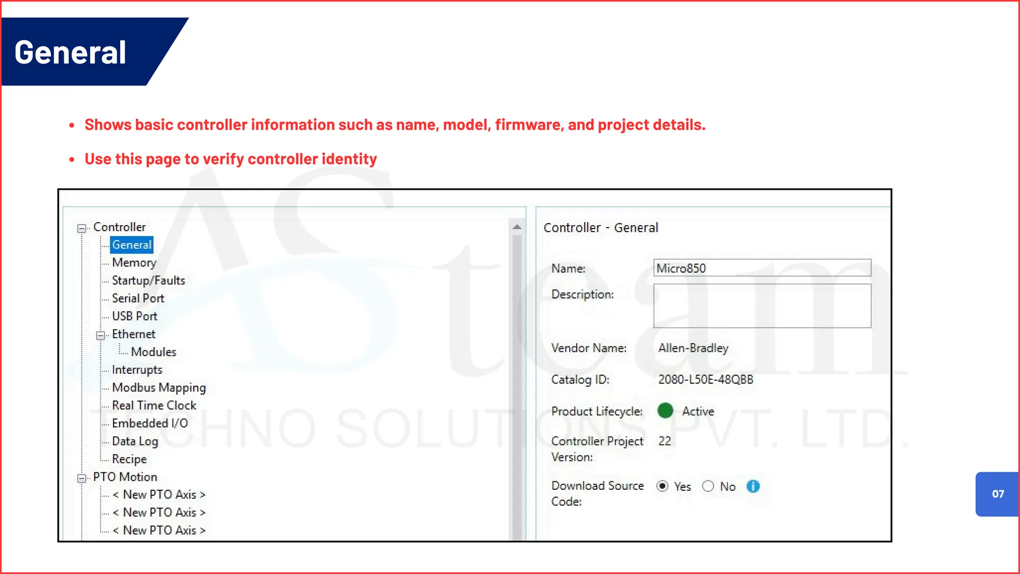
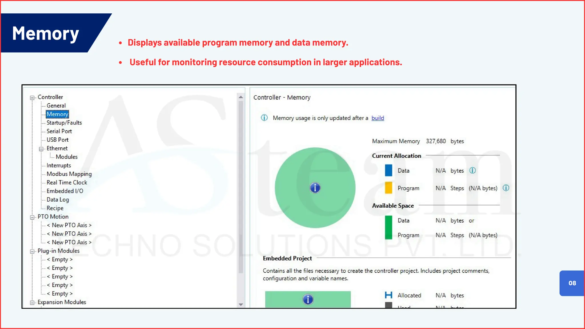
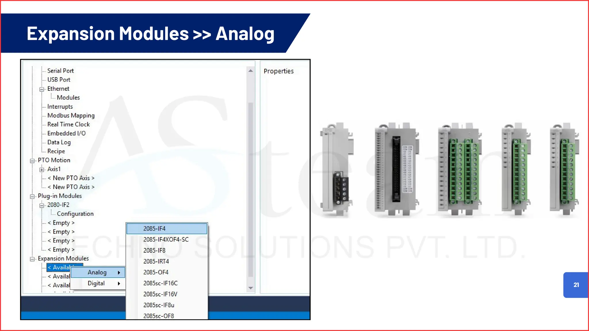
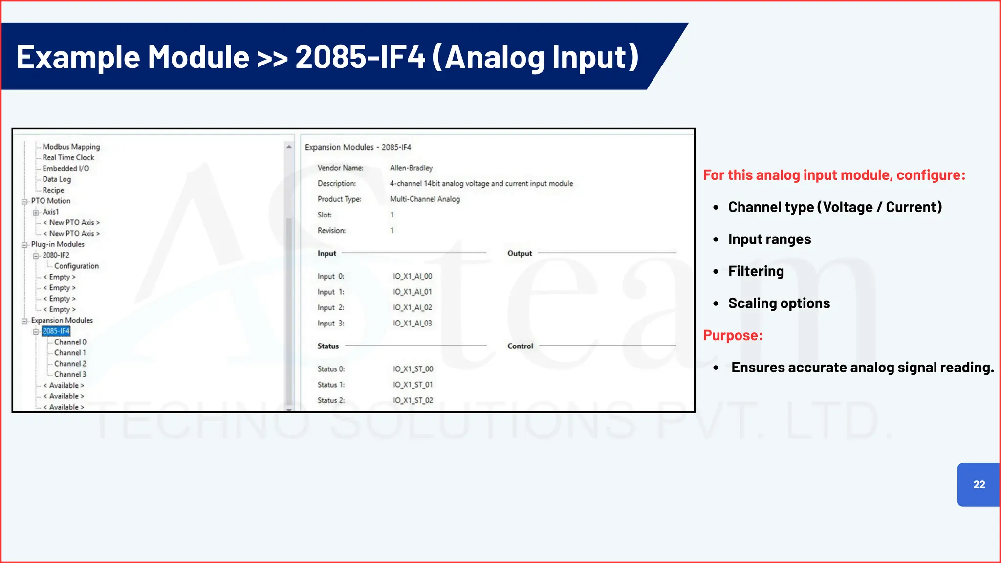
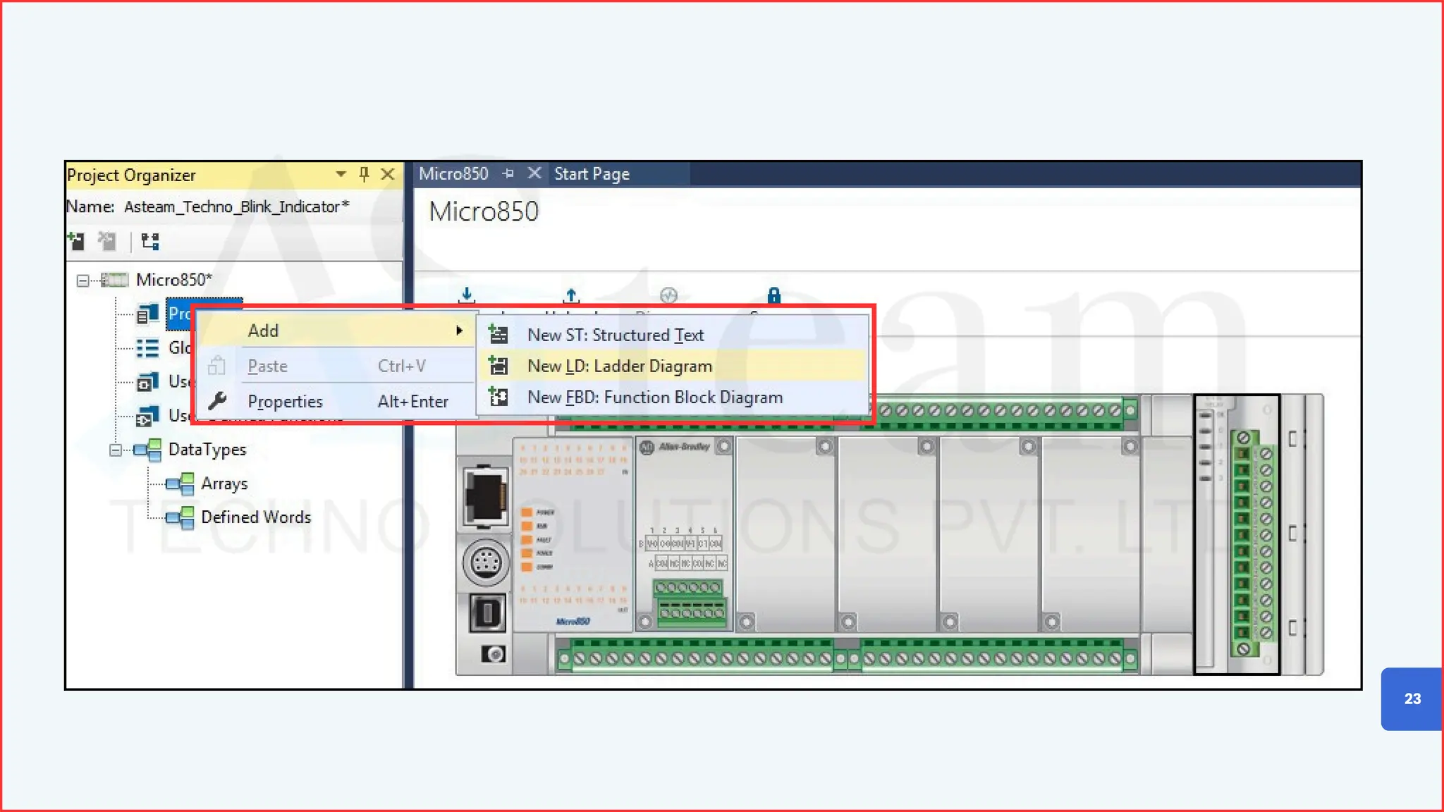
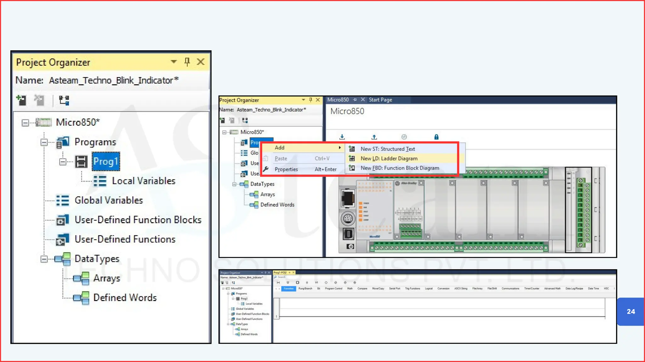


🚀 Sharing a helpful quick-reference guide for automation engineers working with Allen-Bradley Micro800 PLCs. This guide walks you through: • ✅ Creating a new CCW project • 🔌 Connecting the Micro800 controller • 🔧 Setting up firmware & communication paths • 📊 Configuring I/O, modules, and key controller settings It’s useful for commissioning, troubleshooting, and training team members who work with Micro810, Micro820, Micro830, Micro850 or Micro870 controllers. A simple resource that helps avoid common connection issues and saves time on the shop floor.


