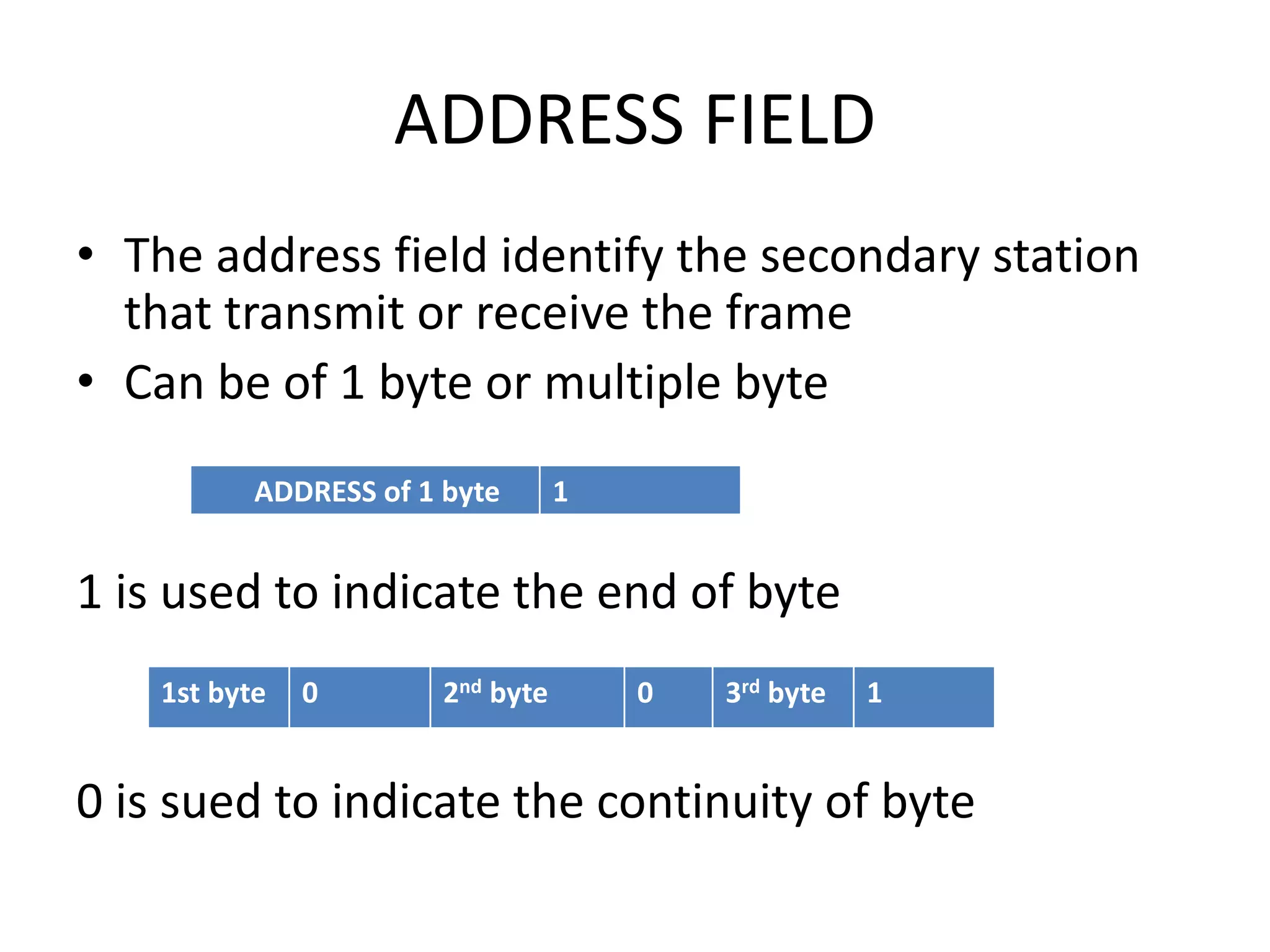
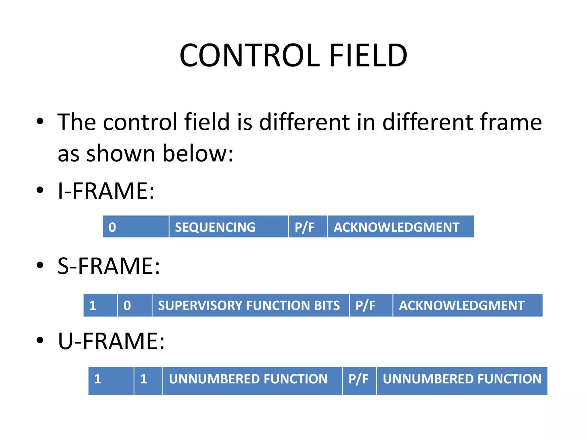
Definition
• HDLC ( high-level data link control)
• HDLC Is a group of protocols and rules for
transmitting data between network points
(called nodes).
• Developed by ISO.
description
• It works of layer 2, (data link) that encapsulate
layer 3 frame
• Data is organized in unit called frame and sent
across a network to the destination that verify
its successful arrival.
• It also manage the flow at which data is sent
• HDLC use synchronous transmission.
DATA LINK CONFIGURATION
• UNBALANCED: consist of one primary and
one(point to point) or more(multipoint)
secondary stations and support both full
duplex and half duplex transmission.
• BALANCED: consist of two combined station
supports both full duplex and half duplex
communication
Data transfer modes/Response modes
• NORMAL RESPOND MODE (NRM): Use unbalanced configuration.
The primary may initiate data transfer to secondary, but the
secondary may only transmit data in response to the command
from the primary.
• ASYNCHRONOUS RESPOND MODE(ARM): Use with an unbalanced
mode. Secondary may initiate transmission without permission of
primary.
• ASYNCHRONOUS BALANCE MODE(ABM): Used with balanced
configuration. Either combined station may initiate the data
without any permission of other combined data.(can only send
information not command and respond to command)
•
STATIONS TYPES
• PRIMARY: responsibility for controlling the operation of the
link,
• handles error recovery
• Frame issued by the primary called command
• SECONDARY: operate under the control of primary
• Frame issued by the secondary called response
• Primary station maintain the logical link with secondary.
•
• COMBINED: Each station can act as both primary and
secondary
FRAMING MODE
• There are three different classes of frames used in HDLC
• (1) I-frame (information frames): which carry actual
information. Such frame can also send ACK.
•
• (2) S-frame ( Supervisory frames): used when sender and
receiver want to sent ACK only, contain no information. It
can also be used for error and flow control.
•
• (3) U-frame (Unnumbered frames): use to link setup,
responsible to maintain terms and argument between the
sender and receiver.
FRAME STRUCTUR
• I-FRAME:
• U-FRAME:
• S-FRAME:
•
FLAG FIELD
• Indicate start and ending frame (closing and
opening flag)
• It indicate the start and ending of frame with a
unique pattern 011111110 which could be
found inside the frame
• To destruct the inner structure a method is
used called bit stuffing
• BIT STUFFING: The sender will insert 0 after
occurrence of 5
ADDRESS FIELD
• The address field identify the secondary station
that transmit or receive the frame
• Can be of 1 byte or multiple byte
1 is used to indicate the end of byte
0 is sued to indicate the continuity of byte
ADDRESS of 1 byte 1
1st byte 0 2nd byte 0 3rd byte 1
INFORMATION FIELD
• Present only in I-frame and some in U-
frame(management information does nit
contain DATA)
• MANAGEMENT INFORMATION: to maintain
the link, response mode, terms and arguments
between sender and receiver.
FCS FIELD
• The frame check sequence (FCS) is an error
detecting code calculated from remaining bit
of frame.
• Exclusive of flag the normal code is 16 bit
CONTROL FIELD
• The control field is different in different frame
as shown below:
• I-FRAME:
• S-FRAME:
• U-FRAME:
0 SEQUENCING P/F ACKNOWLEDGMENT
1 0 SUPERVISORY FUNCTION BITS P/F ACKNOWLEDGMENT
1 1 UNNUMBERED FUNCTION P/F UNNUMBERED FUNCTION
• POLL/FINAL (P/F): tells the direction of frame
• Poll => primary to secondary
• Final => secondary to primary
• Supervisory function: 2 bit code
• 00 = The Receive-ready
• 01 = Receive-not-ready
• 10 = REJ initiates
• 11 = selective reject
• Unnumbered function bit: usually of 32 bits sends large
number of information.
• Sequencing : the informative data that is to be send

Hdlc

  • 2.
    Definition • HDLC (high-level data link control) • HDLC Is a group of protocols and rules for transmitting data between network points (called nodes). • Developed by ISO.
  • 3.
    description • It worksof layer 2, (data link) that encapsulate layer 3 frame • Data is organized in unit called frame and sent across a network to the destination that verify its successful arrival. • It also manage the flow at which data is sent • HDLC use synchronous transmission.
  • 4.
    DATA LINK CONFIGURATION •UNBALANCED: consist of one primary and one(point to point) or more(multipoint) secondary stations and support both full duplex and half duplex transmission. • BALANCED: consist of two combined station supports both full duplex and half duplex communication
  • 5.
    Data transfer modes/Responsemodes • NORMAL RESPOND MODE (NRM): Use unbalanced configuration. The primary may initiate data transfer to secondary, but the secondary may only transmit data in response to the command from the primary. • ASYNCHRONOUS RESPOND MODE(ARM): Use with an unbalanced mode. Secondary may initiate transmission without permission of primary. • ASYNCHRONOUS BALANCE MODE(ABM): Used with balanced configuration. Either combined station may initiate the data without any permission of other combined data.(can only send information not command and respond to command) •
  • 6.
    STATIONS TYPES • PRIMARY:responsibility for controlling the operation of the link, • handles error recovery • Frame issued by the primary called command • SECONDARY: operate under the control of primary • Frame issued by the secondary called response • Primary station maintain the logical link with secondary. • • COMBINED: Each station can act as both primary and secondary
  • 7.
    FRAMING MODE • Thereare three different classes of frames used in HDLC • (1) I-frame (information frames): which carry actual information. Such frame can also send ACK. • • (2) S-frame ( Supervisory frames): used when sender and receiver want to sent ACK only, contain no information. It can also be used for error and flow control. • • (3) U-frame (Unnumbered frames): use to link setup, responsible to maintain terms and argument between the sender and receiver.
  • 8.
    FRAME STRUCTUR • I-FRAME: •U-FRAME: • S-FRAME: •
  • 9.
    FLAG FIELD • Indicatestart and ending frame (closing and opening flag) • It indicate the start and ending of frame with a unique pattern 011111110 which could be found inside the frame • To destruct the inner structure a method is used called bit stuffing • BIT STUFFING: The sender will insert 0 after occurrence of 5
  • 10.
    ADDRESS FIELD • Theaddress field identify the secondary station that transmit or receive the frame • Can be of 1 byte or multiple byte 1 is used to indicate the end of byte 0 is sued to indicate the continuity of byte ADDRESS of 1 byte 1 1st byte 0 2nd byte 0 3rd byte 1
  • 11.
    INFORMATION FIELD • Presentonly in I-frame and some in U- frame(management information does nit contain DATA) • MANAGEMENT INFORMATION: to maintain the link, response mode, terms and arguments between sender and receiver.
  • 12.
    FCS FIELD • Theframe check sequence (FCS) is an error detecting code calculated from remaining bit of frame. • Exclusive of flag the normal code is 16 bit
  • 13.
    CONTROL FIELD • Thecontrol field is different in different frame as shown below: • I-FRAME: • S-FRAME: • U-FRAME: 0 SEQUENCING P/F ACKNOWLEDGMENT 1 0 SUPERVISORY FUNCTION BITS P/F ACKNOWLEDGMENT 1 1 UNNUMBERED FUNCTION P/F UNNUMBERED FUNCTION
  • 14.
    • POLL/FINAL (P/F):tells the direction of frame • Poll => primary to secondary • Final => secondary to primary • Supervisory function: 2 bit code • 00 = The Receive-ready • 01 = Receive-not-ready • 10 = REJ initiates • 11 = selective reject • Unnumbered function bit: usually of 32 bits sends large number of information. • Sequencing : the informative data that is to be send