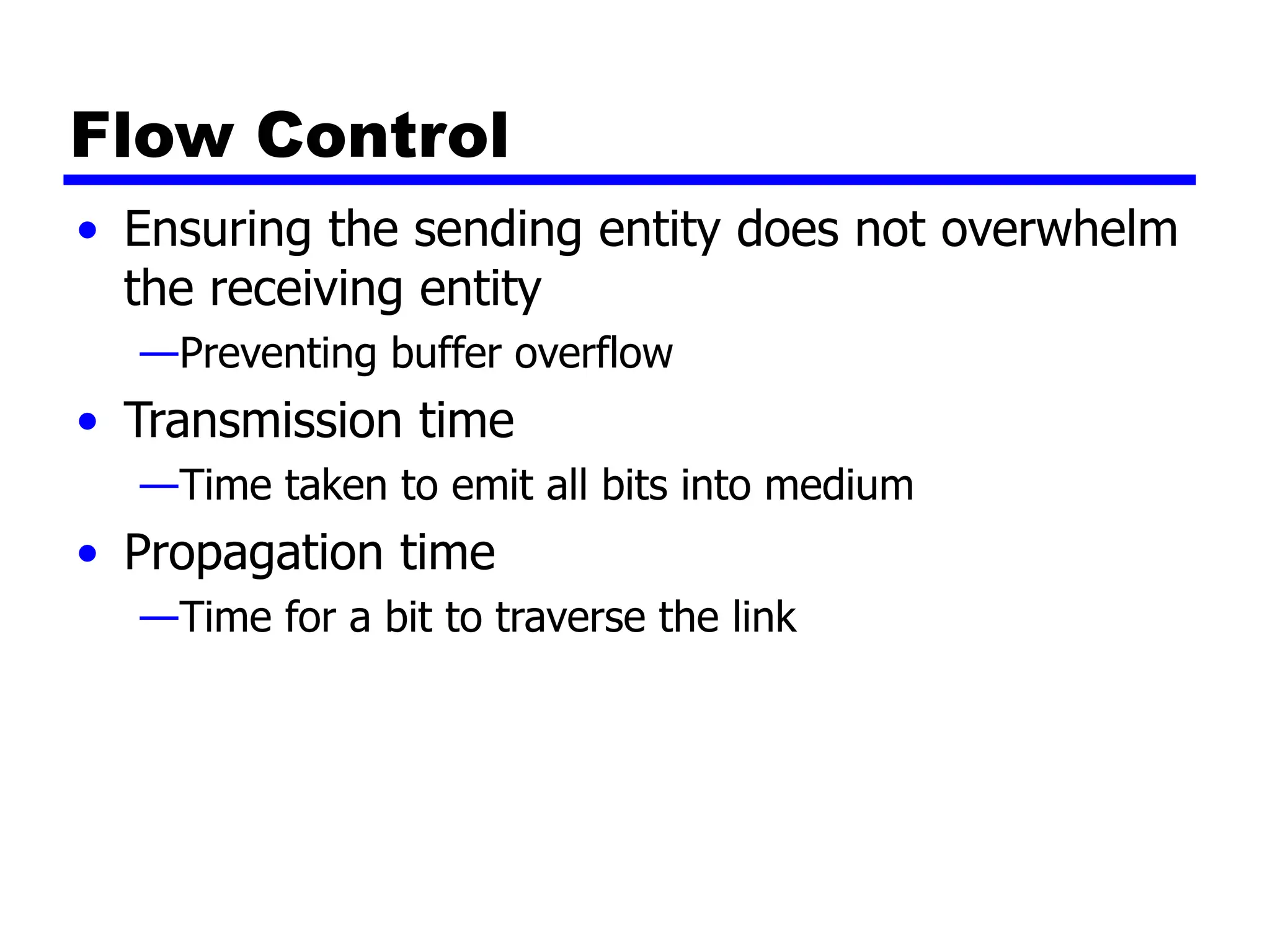
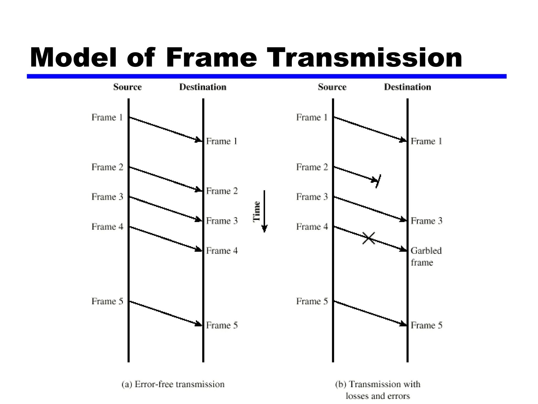
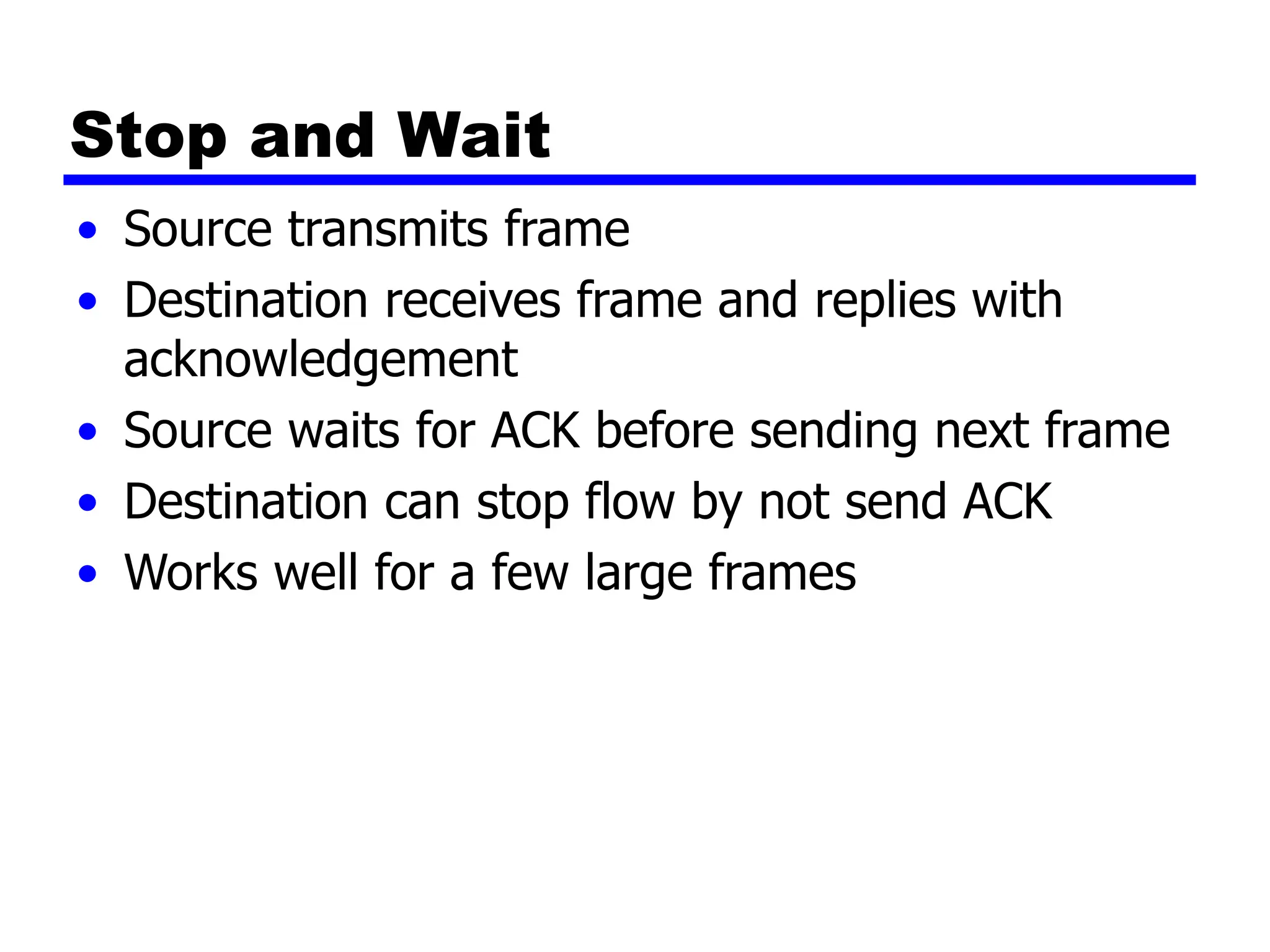
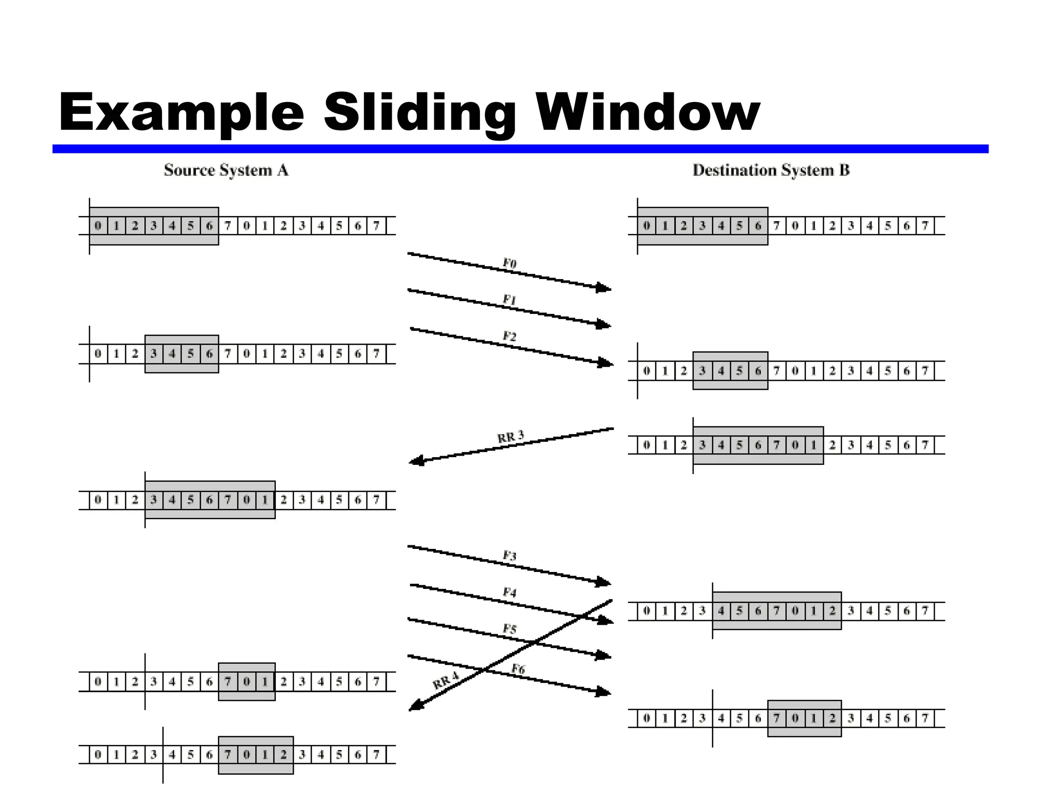
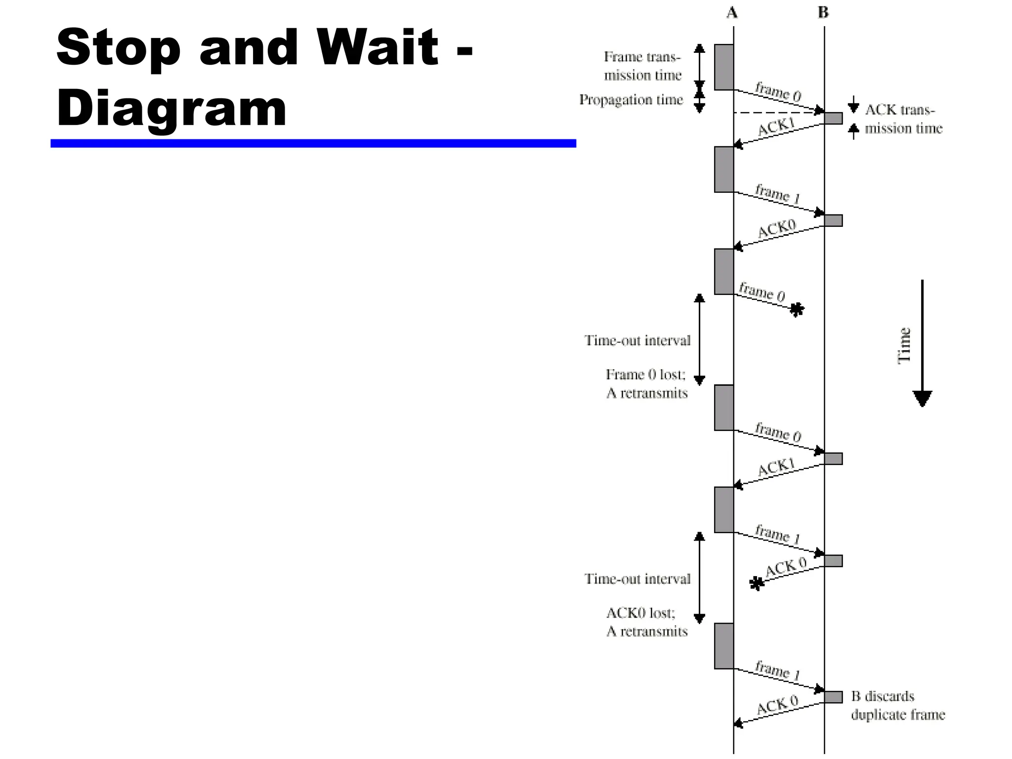
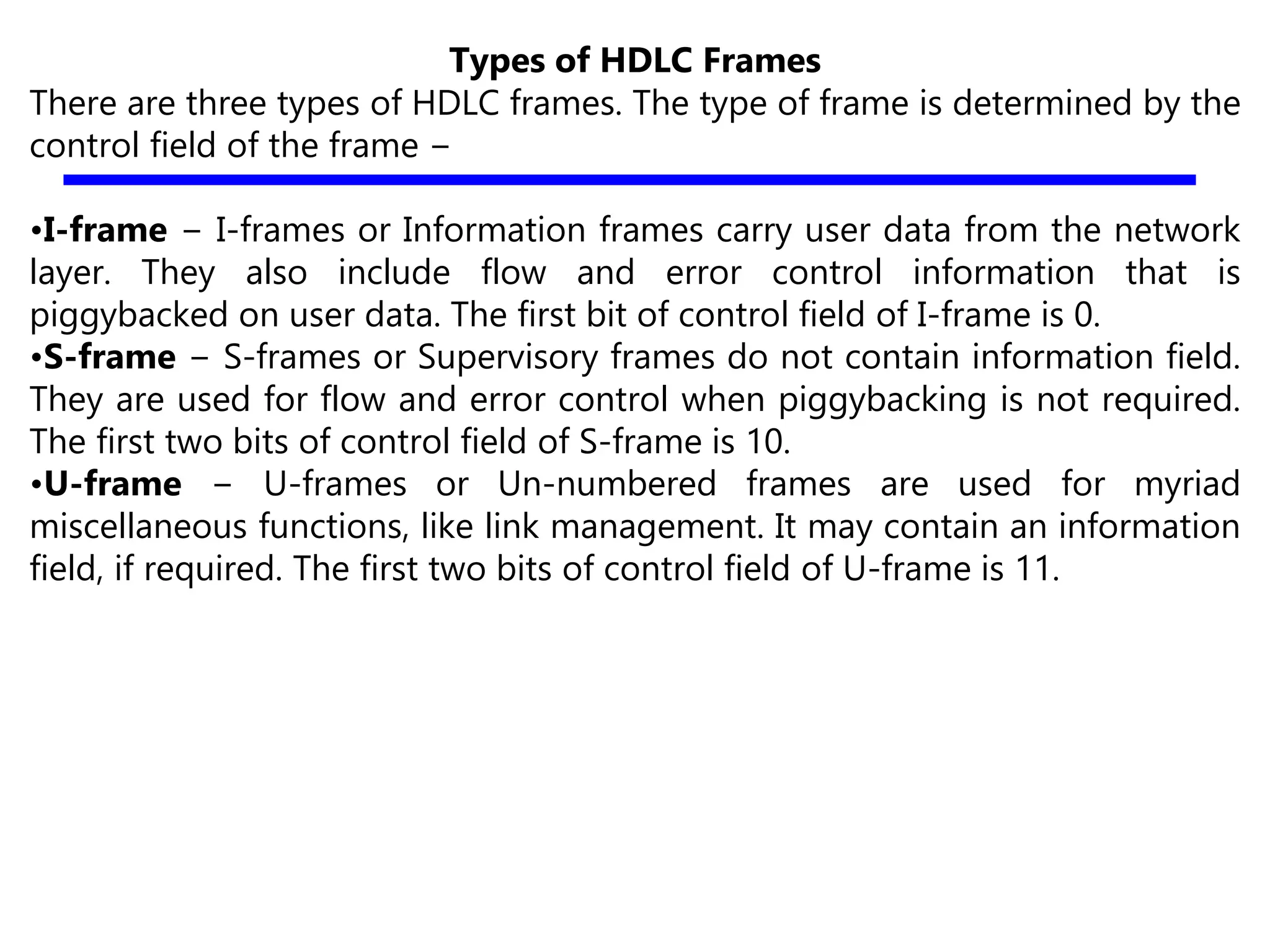
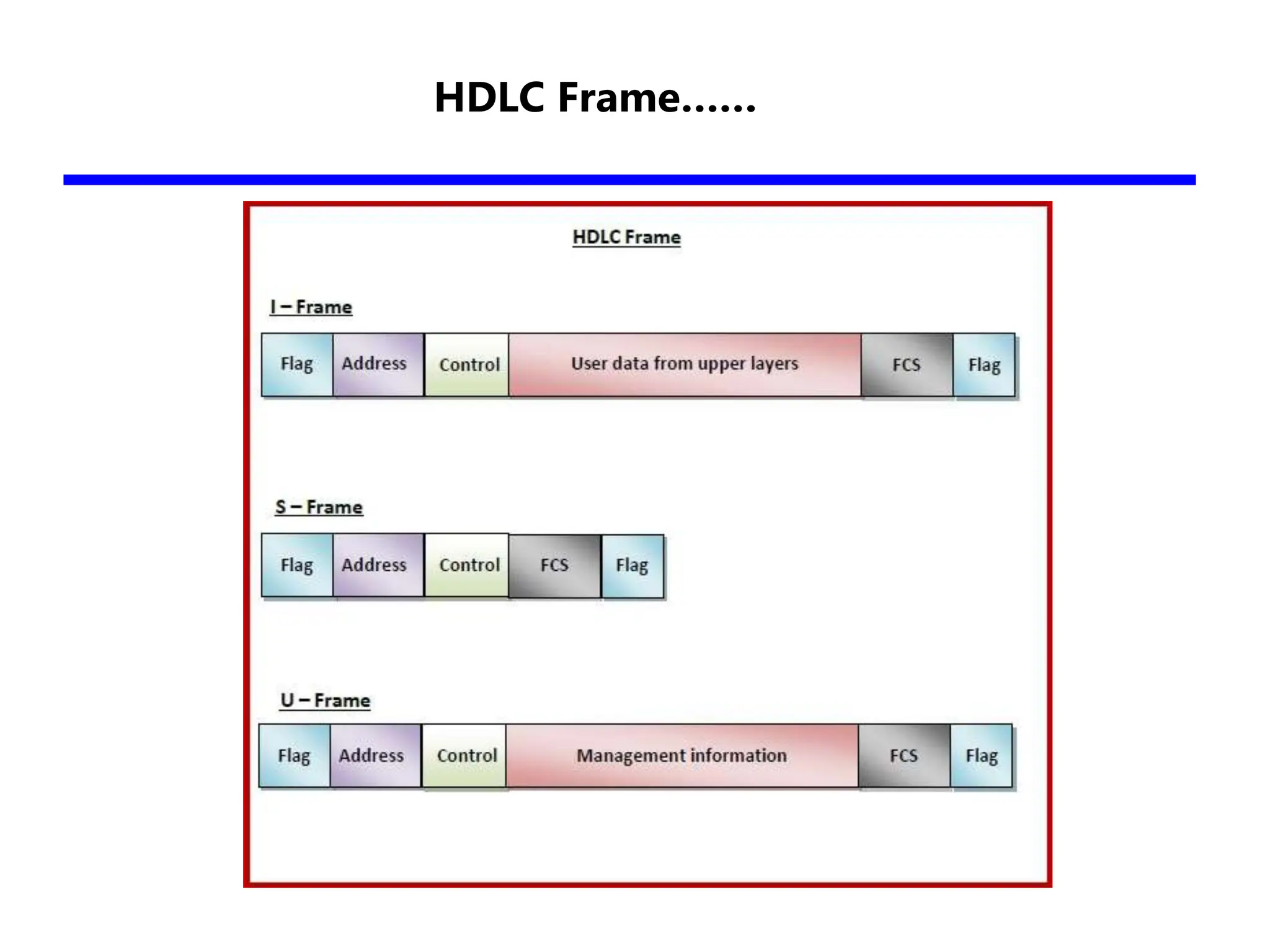
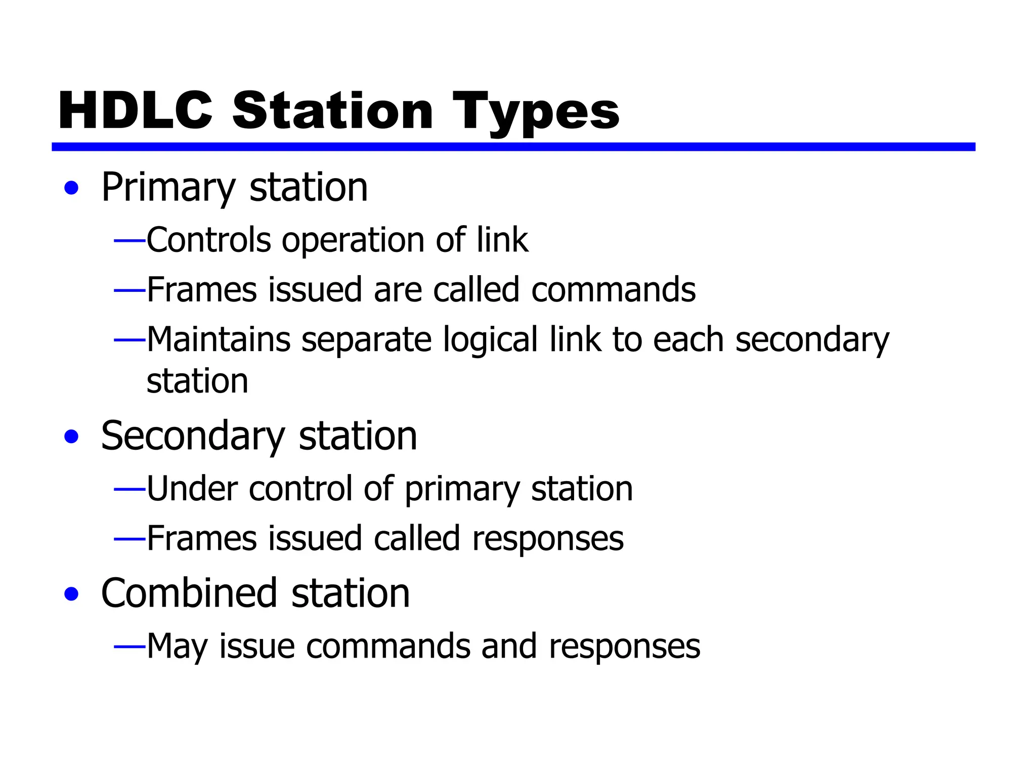
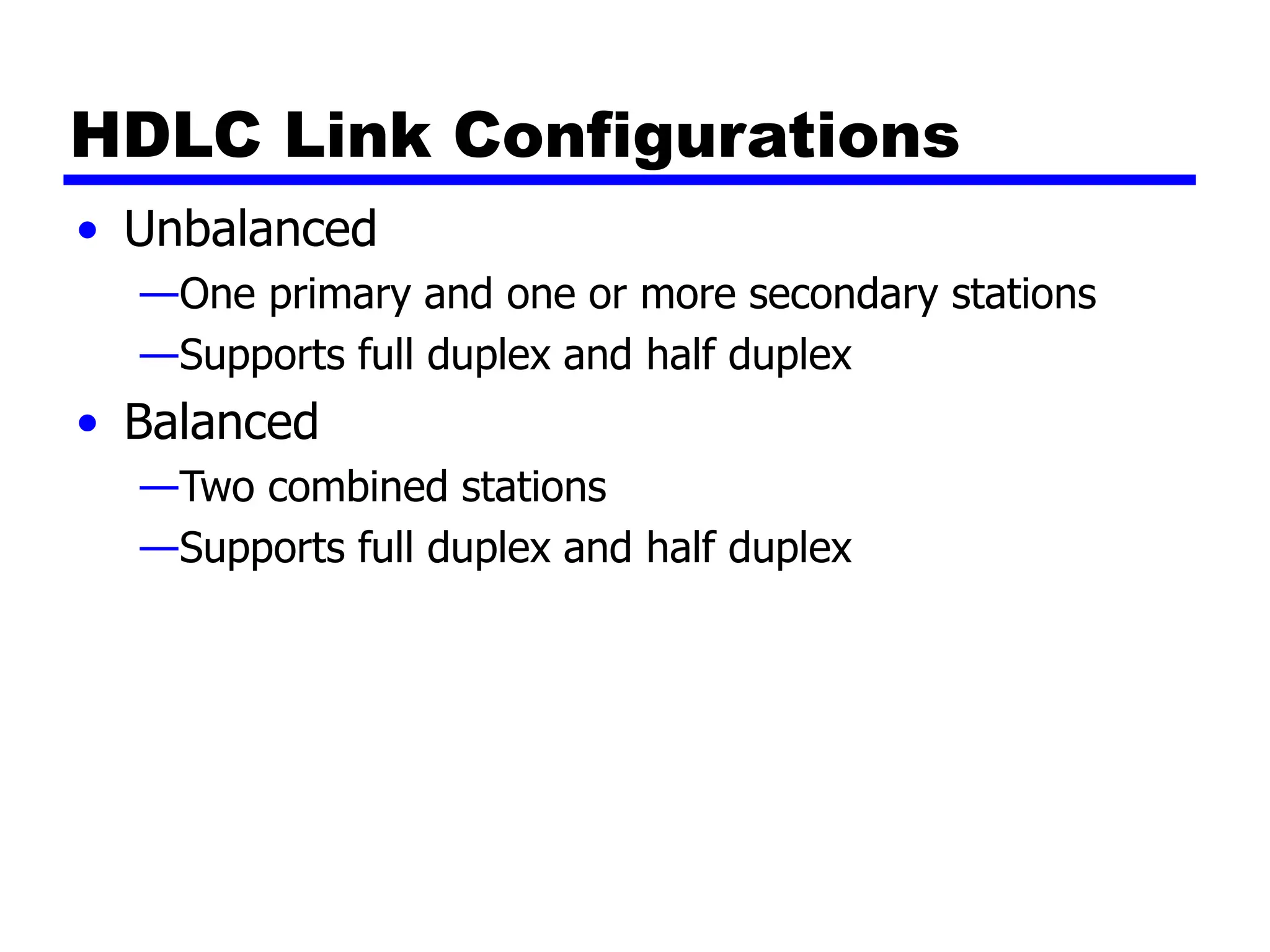
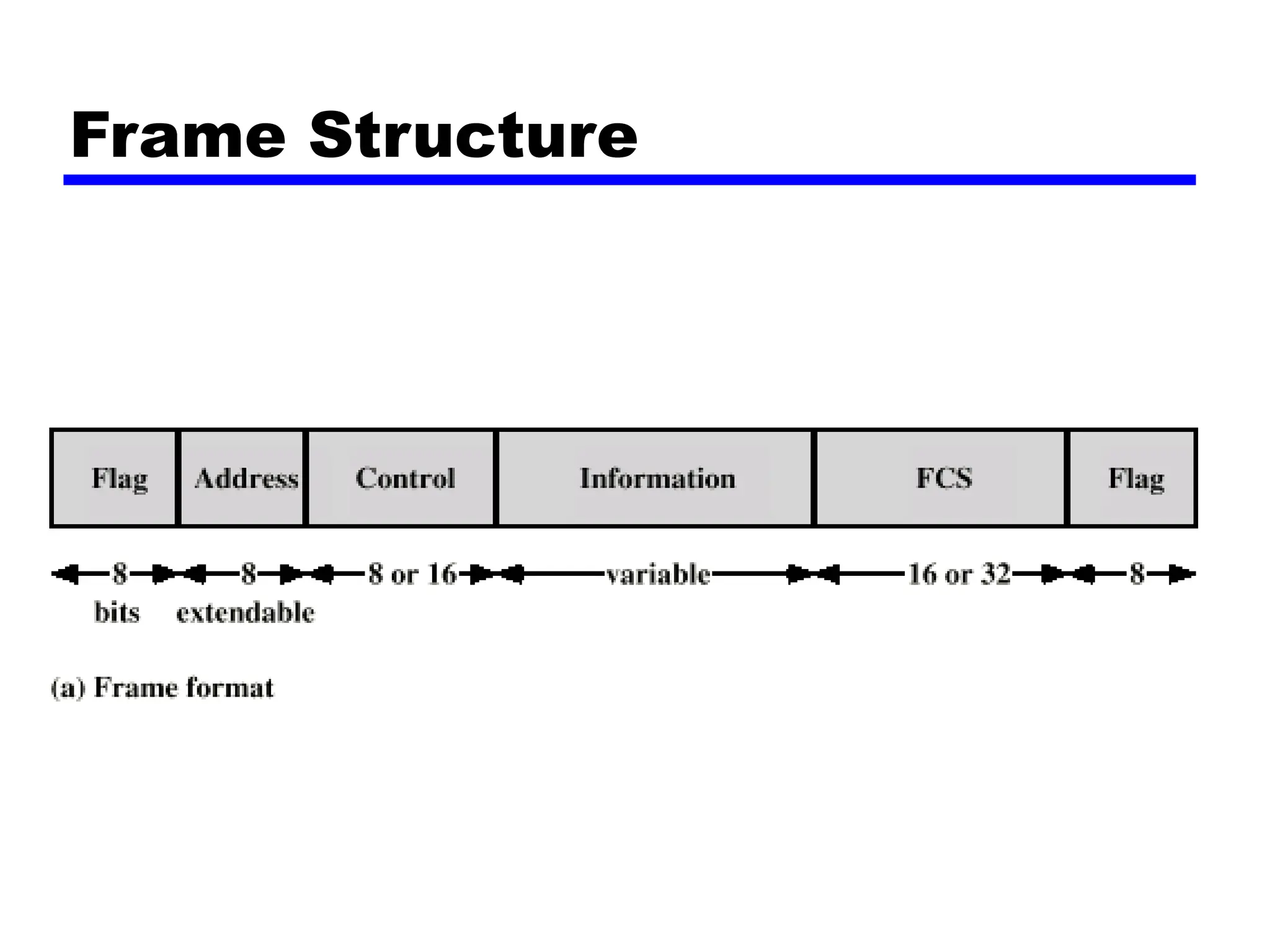
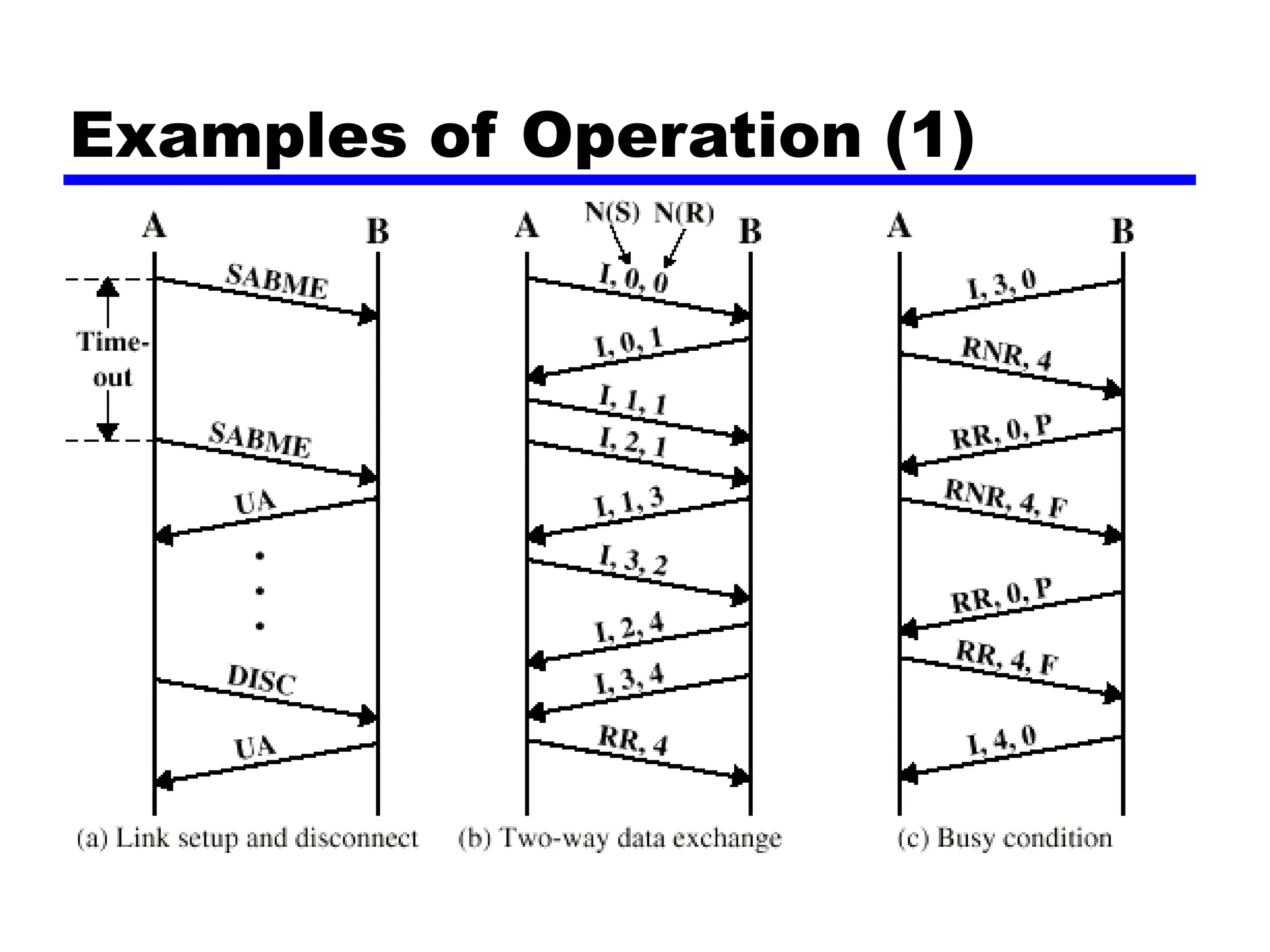
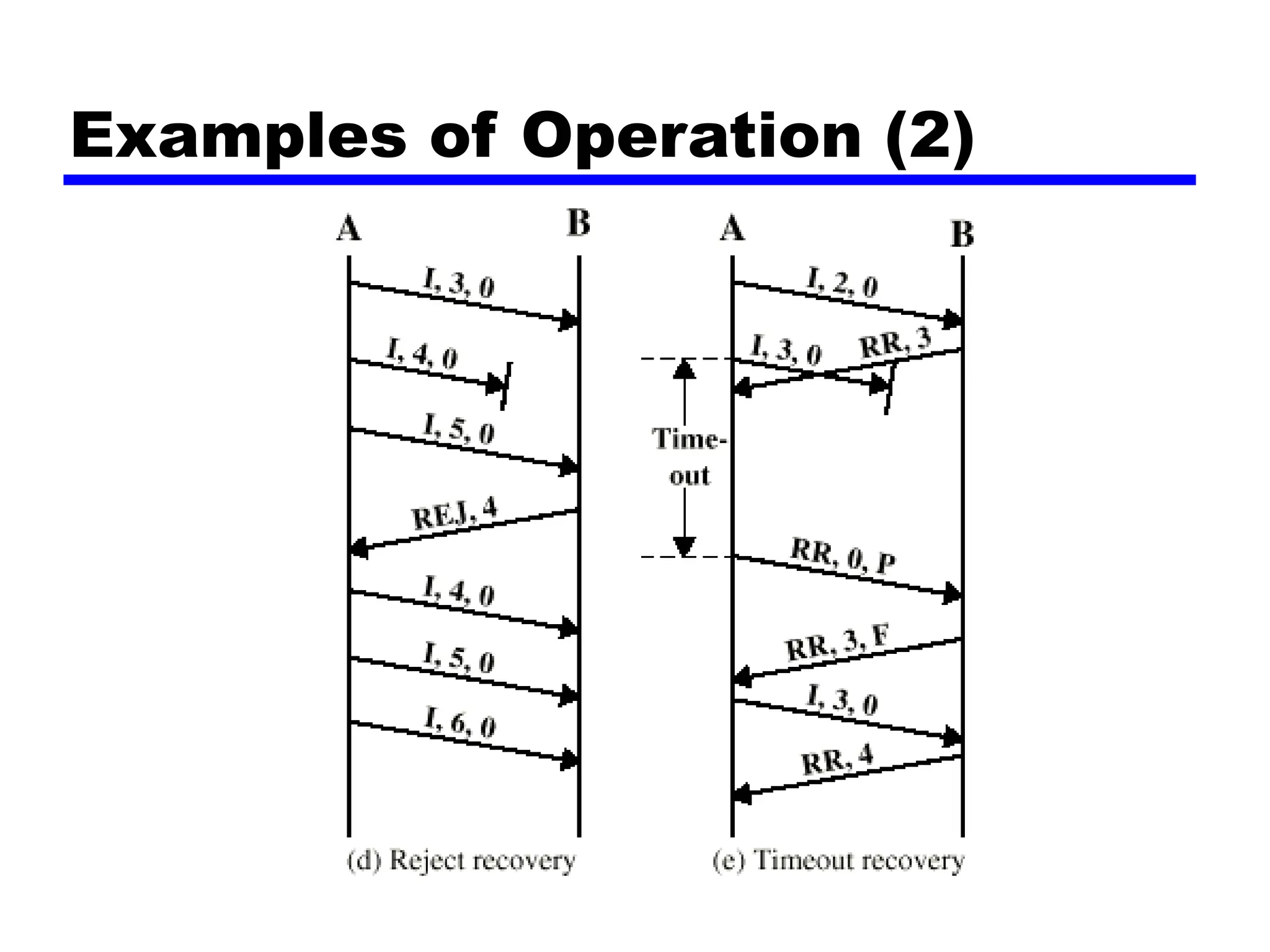
William Stallings
Data and Computer Communications
7th Edition
Chapter 7: Data Link Control Protocols
Flow Control
• Ensuring the sending entity does not overwhelm
the receiving entity
—Preventing buffer overflow
• Transmission time
—Time taken to emit all bits into medium
• Propagation time
—Time for a bit to traverse the link
Model of Frame Transmission
Stop and Wait
• Source transmits frame
• Destination receives frame and replies with
acknowledgement
• Source waits for ACK before sending next frame
• Destination can stop flow by not send ACK
• Works well for a few large frames
Fragmentation
• Large block of data may be split into small
frames
—Limited buffer size
—Errors detected sooner (when whole frame received)
—On error, retransmission of smaller frames is needed
—Prevents one station occupying medium for long
periods
• Stop and wait becomes inadequate
Stop and Wait Link Utilization
Sliding Windows Flow Control
• Allow multiple frames to be in transit
• Receiver has buffer W long
• Transmitter can send up to W frames without
ACK
• Each frame is numbered
• ACK includes number of next frame expected
• Sequence number bounded by size of field (k)
—Frames are numbered modulo 2k
Sliding Window Diagram
Example Sliding Window
Sliding Window Enhancements
• Receiver can acknowledge frames without
permitting further transmission (Receive Not
Ready)
• Must send a normal acknowledge to resume
• If duplex, use piggybacking
—If no data to send, use acknowledgement frame
—If data but no acknowledgement to send, send last
acknowledgement number again, or have ACK valid
flag (TCP)
Error Detection
• Additional bits added by transmitter for error
detection code
• Parity
—Value of parity bit is such that character has even
(even parity) or odd (odd parity) number of ones
—Even number of bit errors goes undetected
Cyclic Redundancy Check
• For a block of k bits transmitter generates n bit
sequence
• Transmit k+n bits which is exactly divisible by
some number
• Receive divides frame by that number
—If no remainder, assume no error
—For math, see Stallings chapter 7
Error Control
• Detection and correction of errors
• Lost frames
• Damaged frames
• Automatic repeat request
—Error detection
—Positive acknowledgment
—Retransmission after timeout
—Negative acknowledgement and retransmission
Automatic Repeat Request
(ARQ)
• Stop and wait
• Go back N
• Selective reject (selective retransmission)
Stop and Wait
• Source transmits single frame
• Wait for ACK
• If received frame damaged, discard it
—Transmitter has timeout
—If no ACK within timeout, retransmit
• If ACK damaged,transmitter will not recognize it
—Transmitter will retransmit
—Receive gets two copies of frame
—Use ACK0 and ACK1
Stop and Wait -
Diagram
Stop and Wait - Pros and Cons
• Simple
• Inefficient
Go Back N (1)
• Based on sliding window
• If no error, ACK as usual with next frame
expected
• Use window to control number of outstanding
frames
• If error, reply with rejection
—Discard that frame and all future frames until error
frame received correctly
—Transmitter must go back and retransmit that frame
and all subsequent frames
Go Back N - Damaged Frame
• Receiver detects error in frame i
• Receiver sends rejection-i
• Transmitter gets rejection-i
• Transmitter retransmits frame i and all
subsequent
Go Back N - Lost Frame (1)
• Frame i lost
• Transmitter sends i+1
• Receiver gets frame i+1 out of sequence
• Receiver send reject i
• Transmitter goes back to frame i and
retransmits
Go Back N - Lost Frame (2)
• Frame i lost and no additional frame sent
• Receiver gets nothing and returns neither
acknowledgement nor rejection
• Transmitter times out and sends
acknowledgement frame with P bit set to 1
• Receiver interprets this as command which it
acknowledges with the number of the next
frame it expects (frame i )
• Transmitter then retransmits frame i
Go Back N - Damaged
Acknowledgement
• Receiver gets frame i and send
acknowledgement (i+1) which is lost
• Acknowledgements are cumulative, so next
acknowledgement (i+n) may arrive before
transmitter times out on frame i
• If transmitter times out, it sends
acknowledgement with P bit set as before
• This can be repeated a number of times before
a reset procedure is initiated
Go Back N - Damaged Rejection
• As for lost frame (2)
Go Back N -
Diagram
Selective Reject
• Also called selective retransmission
• Only rejected frames are retransmitted
• Subsequent frames are accepted by the receiver
and buffered
• Minimizes retransmission
• Receiver must maintain large enough buffer
• More complex login in transmitter
Selective Reject -
Diagram
High Level Data Link Control
High-level Data Link Control (HDLC) is a group of communication
protocols of the data link layer for transmitting data between network
points or nodes. Since it is a data link protocol, data is organized into
frames. A frame is transmitted via the network to the destination that
verifies its successful arrival. It is a bit - oriented protocol that is
applicable for both point - to - point and multipoint communications.
HDLC Frame
HDLC is a bit - oriented protocol where each frame contains up to six fields.
HDLC frame are −
•Flag − It is an 8-bit sequence that marks the beginning and the end of the
frame. The bit pattern of the flag is 01111110.
•Address − It contains the address of the receiver. If the frame is sent by
the primary station, it contains the address(es) of the secondary station(s). If
it is sent by the secondary station, it contains the address of the primary
station. The address field may be from 1 byte to several bytes.
•Control − It is 1 or 2 bytes containing flow and error control information.
•Payload − This carries the data from the network layer. Its length may vary
from one network to another.
•FCS − It is a 2 byte or 4 bytes frame check sequence for error detection.
The standard code used is CRC (cyclic redundancy code)
FCS=frame check sequence
Types of HDLC Frames
There are three types of HDLC frames. The type of frame is determined by the
control field of the frame −
•I-frame − I-frames or Information frames carry user data from the network
layer. They also include flow and error control information that is
piggybacked on user data. The first bit of control field of I-frame is 0.
•S-frame − S-frames or Supervisory frames do not contain information field.
They are used for flow and error control when piggybacking is not required.
The first two bits of control field of S-frame is 10.
•U-frame − U-frames or Un-numbered frames are used for myriad
miscellaneous functions, like link management. It may contain an information
field, if required. The first two bits of control field of U-frame is 11.
HDLC Frame……
HDLC Station Types
• Primary station
—Controls operation of link
—Frames issued are called commands
—Maintains separate logical link to each secondary
station
• Secondary station
—Under control of primary station
—Frames issued called responses
• Combined station
—May issue commands and responses
HDLC Link Configurations
• Unbalanced
—One primary and one or more secondary stations
—Supports full duplex and half duplex
• Balanced
—Two combined stations
—Supports full duplex and half duplex
HDLC Transfer Modes (1)
• Normal Response Mode (NRM)
—Unbalanced configuration
—Primary initiates transfer to secondary
—Secondary may only transmit data in response to
command from primary
—Used on multi-drop lines
—Host computer as primary
—Terminals as secondary
HDLC Transfer Modes (2)
• Asynchronous Balanced Mode (ABM)
—Balanced configuration
—Either station may initiate transmission without
receiving permission
—Most widely used
—No polling overhead
HDLC Transfer Modes (3)
• Asynchronous Response Mode (ARM)
—Unbalanced configuration
—Secondary may initiate transmission without
permission form primary
—Primary responsible for line
—rarely used
Frame Structure
• Synchronous transmission
• All transmissions in frames
• Single frame format for all data and control
exchanges
Frame Structure
Flag Fields
• Delimit frame at both ends
• 01111110
• May close one frame and open another
• Receiver hunts for flag sequence to synchronize
• Bit stuffing used to avoid confusion with data containing
01111110
— 0 inserted after every sequence of five 1s
— If receiver detects five 1s it checks next bit
— If 0, it is deleted
— If 1 and seventh bit is 0, accept as flag
— If sixth and seventh bits 1, sender is indicating abort
Bit Stuffing
• Example with
possible errors
Bit stuffing is the insertion of non information bits into data.
Note that stuffed bits should not be confused with overhead
bits.
Address Field
• Identifies secondary station that sent or will receive
frame
• Usually 8 bits long
• May be extended to multiples of 7 bits
— LSB of each octet indicates that it is the last octet (1) or not (0)
• All ones (11111111) is broadcast
Control Field
• Different for different frame type
—Information - data to be transmitted to user (next
layer up)
• Flow and error control piggybacked on information frames
—Supervisory - ARQ when piggyback not used
—Unnumbered - supplementary link control
• First one or two bits of control filed identify
frame type
• Remaining bits explained later
Control Field Diagram
Poll/Final Bit
• Use depends on context
• Command frame
—P bit
—1 to solicit (poll) response from peer
• Response frame
—F bit
—1 indicates response to soliciting command
Information Field
• Only in information and some unnumbered
frames
• Must contain integral number of octets
• Variable length
Frame Check Sequence Field
• FCS
• Error detection
• 16 bit CRC
• Optional 32 bit CRC
HDLC Operation
• Exchange of information, supervisory and
unnumbered frames
• Three phases
—Initialization
—Data transfer
—Disconnect
Examples of Operation (1)
Examples of Operation (2)
References
• Stallings chapter 7
• Web sites on HDLC

a_presentation_on_hdlc_and_dlc_computer.ppt

  • 1.
    William Stallings Data andComputer Communications 7th Edition Chapter 7: Data Link Control Protocols
  • 2.
    Flow Control • Ensuringthe sending entity does not overwhelm the receiving entity —Preventing buffer overflow • Transmission time —Time taken to emit all bits into medium • Propagation time —Time for a bit to traverse the link
  • 3.
    Model of FrameTransmission
  • 4.
    Stop and Wait •Source transmits frame • Destination receives frame and replies with acknowledgement • Source waits for ACK before sending next frame • Destination can stop flow by not send ACK • Works well for a few large frames
  • 5.
    Fragmentation • Large blockof data may be split into small frames —Limited buffer size —Errors detected sooner (when whole frame received) —On error, retransmission of smaller frames is needed —Prevents one station occupying medium for long periods • Stop and wait becomes inadequate
  • 6.
    Stop and WaitLink Utilization
  • 7.
    Sliding Windows FlowControl • Allow multiple frames to be in transit • Receiver has buffer W long • Transmitter can send up to W frames without ACK • Each frame is numbered • ACK includes number of next frame expected • Sequence number bounded by size of field (k) —Frames are numbered modulo 2k
  • 8.
  • 9.
  • 10.
    Sliding Window Enhancements •Receiver can acknowledge frames without permitting further transmission (Receive Not Ready) • Must send a normal acknowledge to resume • If duplex, use piggybacking —If no data to send, use acknowledgement frame —If data but no acknowledgement to send, send last acknowledgement number again, or have ACK valid flag (TCP)
  • 11.
    Error Detection • Additionalbits added by transmitter for error detection code • Parity —Value of parity bit is such that character has even (even parity) or odd (odd parity) number of ones —Even number of bit errors goes undetected
  • 12.
    Cyclic Redundancy Check •For a block of k bits transmitter generates n bit sequence • Transmit k+n bits which is exactly divisible by some number • Receive divides frame by that number —If no remainder, assume no error —For math, see Stallings chapter 7
  • 13.
    Error Control • Detectionand correction of errors • Lost frames • Damaged frames • Automatic repeat request —Error detection —Positive acknowledgment —Retransmission after timeout —Negative acknowledgement and retransmission
  • 14.
    Automatic Repeat Request (ARQ) •Stop and wait • Go back N • Selective reject (selective retransmission)
  • 15.
    Stop and Wait •Source transmits single frame • Wait for ACK • If received frame damaged, discard it —Transmitter has timeout —If no ACK within timeout, retransmit • If ACK damaged,transmitter will not recognize it —Transmitter will retransmit —Receive gets two copies of frame —Use ACK0 and ACK1
  • 16.
    Stop and Wait- Diagram
  • 17.
    Stop and Wait- Pros and Cons • Simple • Inefficient
  • 18.
    Go Back N(1) • Based on sliding window • If no error, ACK as usual with next frame expected • Use window to control number of outstanding frames • If error, reply with rejection —Discard that frame and all future frames until error frame received correctly —Transmitter must go back and retransmit that frame and all subsequent frames
  • 19.
    Go Back N- Damaged Frame • Receiver detects error in frame i • Receiver sends rejection-i • Transmitter gets rejection-i • Transmitter retransmits frame i and all subsequent
  • 20.
    Go Back N- Lost Frame (1) • Frame i lost • Transmitter sends i+1 • Receiver gets frame i+1 out of sequence • Receiver send reject i • Transmitter goes back to frame i and retransmits
  • 21.
    Go Back N- Lost Frame (2) • Frame i lost and no additional frame sent • Receiver gets nothing and returns neither acknowledgement nor rejection • Transmitter times out and sends acknowledgement frame with P bit set to 1 • Receiver interprets this as command which it acknowledges with the number of the next frame it expects (frame i ) • Transmitter then retransmits frame i
  • 22.
    Go Back N- Damaged Acknowledgement • Receiver gets frame i and send acknowledgement (i+1) which is lost • Acknowledgements are cumulative, so next acknowledgement (i+n) may arrive before transmitter times out on frame i • If transmitter times out, it sends acknowledgement with P bit set as before • This can be repeated a number of times before a reset procedure is initiated
  • 23.
    Go Back N- Damaged Rejection • As for lost frame (2)
  • 24.
    Go Back N- Diagram
  • 25.
    Selective Reject • Alsocalled selective retransmission • Only rejected frames are retransmitted • Subsequent frames are accepted by the receiver and buffered • Minimizes retransmission • Receiver must maintain large enough buffer • More complex login in transmitter
  • 26.
  • 27.
    High Level DataLink Control High-level Data Link Control (HDLC) is a group of communication protocols of the data link layer for transmitting data between network points or nodes. Since it is a data link protocol, data is organized into frames. A frame is transmitted via the network to the destination that verifies its successful arrival. It is a bit - oriented protocol that is applicable for both point - to - point and multipoint communications.
  • 28.
    HDLC Frame HDLC isa bit - oriented protocol where each frame contains up to six fields. HDLC frame are − •Flag − It is an 8-bit sequence that marks the beginning and the end of the frame. The bit pattern of the flag is 01111110. •Address − It contains the address of the receiver. If the frame is sent by the primary station, it contains the address(es) of the secondary station(s). If it is sent by the secondary station, it contains the address of the primary station. The address field may be from 1 byte to several bytes. •Control − It is 1 or 2 bytes containing flow and error control information. •Payload − This carries the data from the network layer. Its length may vary from one network to another. •FCS − It is a 2 byte or 4 bytes frame check sequence for error detection. The standard code used is CRC (cyclic redundancy code) FCS=frame check sequence
  • 29.
    Types of HDLCFrames There are three types of HDLC frames. The type of frame is determined by the control field of the frame − •I-frame − I-frames or Information frames carry user data from the network layer. They also include flow and error control information that is piggybacked on user data. The first bit of control field of I-frame is 0. •S-frame − S-frames or Supervisory frames do not contain information field. They are used for flow and error control when piggybacking is not required. The first two bits of control field of S-frame is 10. •U-frame − U-frames or Un-numbered frames are used for myriad miscellaneous functions, like link management. It may contain an information field, if required. The first two bits of control field of U-frame is 11.
  • 30.
  • 31.
    HDLC Station Types •Primary station —Controls operation of link —Frames issued are called commands —Maintains separate logical link to each secondary station • Secondary station —Under control of primary station —Frames issued called responses • Combined station —May issue commands and responses
  • 32.
    HDLC Link Configurations •Unbalanced —One primary and one or more secondary stations —Supports full duplex and half duplex • Balanced —Two combined stations —Supports full duplex and half duplex
  • 33.
    HDLC Transfer Modes(1) • Normal Response Mode (NRM) —Unbalanced configuration —Primary initiates transfer to secondary —Secondary may only transmit data in response to command from primary —Used on multi-drop lines —Host computer as primary —Terminals as secondary
  • 34.
    HDLC Transfer Modes(2) • Asynchronous Balanced Mode (ABM) —Balanced configuration —Either station may initiate transmission without receiving permission —Most widely used —No polling overhead
  • 35.
    HDLC Transfer Modes(3) • Asynchronous Response Mode (ARM) —Unbalanced configuration —Secondary may initiate transmission without permission form primary —Primary responsible for line —rarely used
  • 36.
    Frame Structure • Synchronoustransmission • All transmissions in frames • Single frame format for all data and control exchanges
  • 37.
  • 38.
    Flag Fields • Delimitframe at both ends • 01111110 • May close one frame and open another • Receiver hunts for flag sequence to synchronize • Bit stuffing used to avoid confusion with data containing 01111110 — 0 inserted after every sequence of five 1s — If receiver detects five 1s it checks next bit — If 0, it is deleted — If 1 and seventh bit is 0, accept as flag — If sixth and seventh bits 1, sender is indicating abort
  • 39.
    Bit Stuffing • Examplewith possible errors
  • 40.
    Bit stuffing isthe insertion of non information bits into data. Note that stuffed bits should not be confused with overhead bits.
  • 41.
    Address Field • Identifiessecondary station that sent or will receive frame • Usually 8 bits long • May be extended to multiples of 7 bits — LSB of each octet indicates that it is the last octet (1) or not (0) • All ones (11111111) is broadcast
  • 42.
    Control Field • Differentfor different frame type —Information - data to be transmitted to user (next layer up) • Flow and error control piggybacked on information frames —Supervisory - ARQ when piggyback not used —Unnumbered - supplementary link control • First one or two bits of control filed identify frame type • Remaining bits explained later
  • 43.
  • 44.
    Poll/Final Bit • Usedepends on context • Command frame —P bit —1 to solicit (poll) response from peer • Response frame —F bit —1 indicates response to soliciting command
  • 45.
    Information Field • Onlyin information and some unnumbered frames • Must contain integral number of octets • Variable length
  • 46.
    Frame Check SequenceField • FCS • Error detection • 16 bit CRC • Optional 32 bit CRC
  • 47.
    HDLC Operation • Exchangeof information, supervisory and unnumbered frames • Three phases —Initialization —Data transfer —Disconnect
  • 48.
  • 49.
  • 50.
    References • Stallings chapter7 • Web sites on HDLC