Downloaded 1,356 times
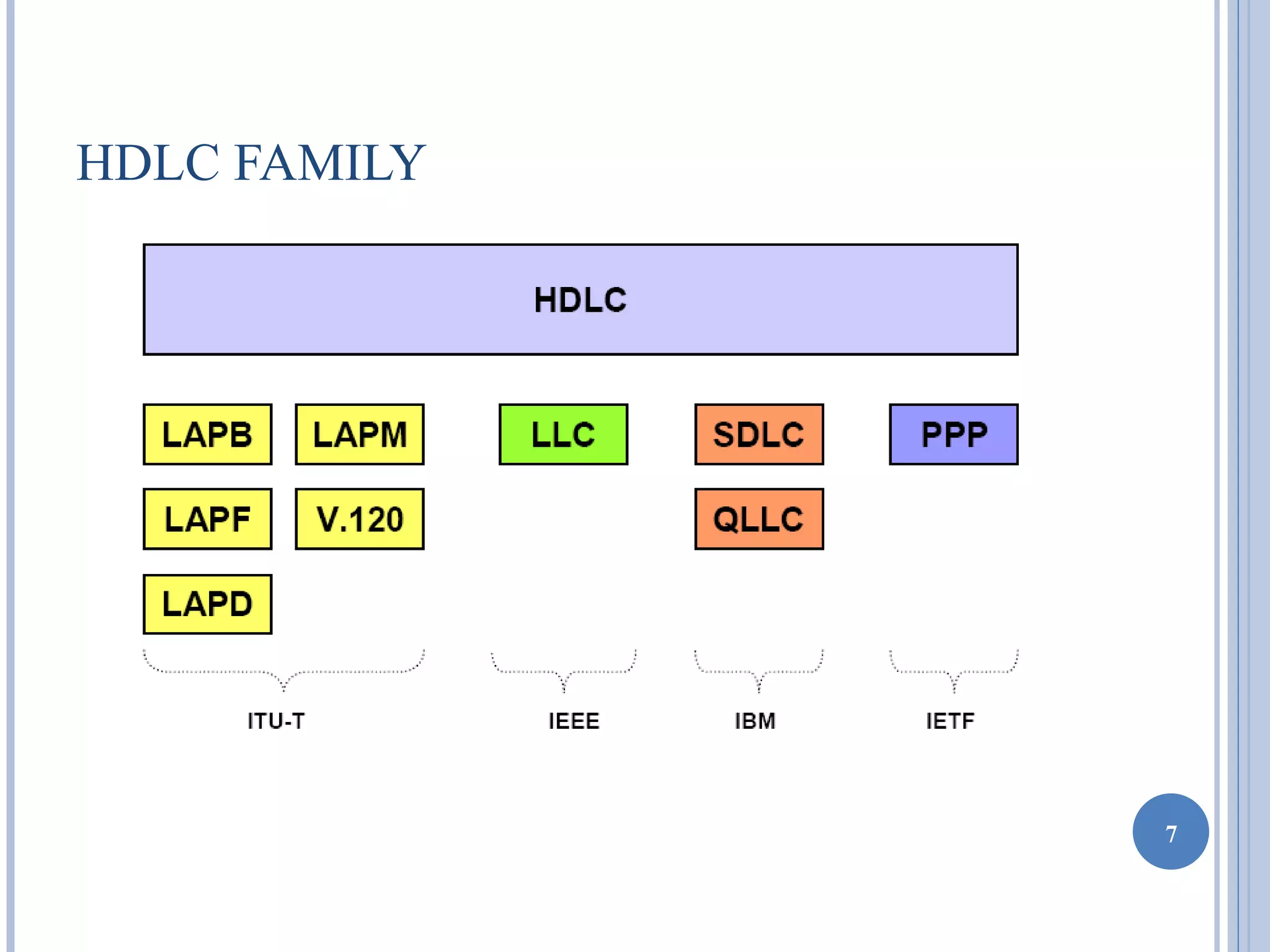
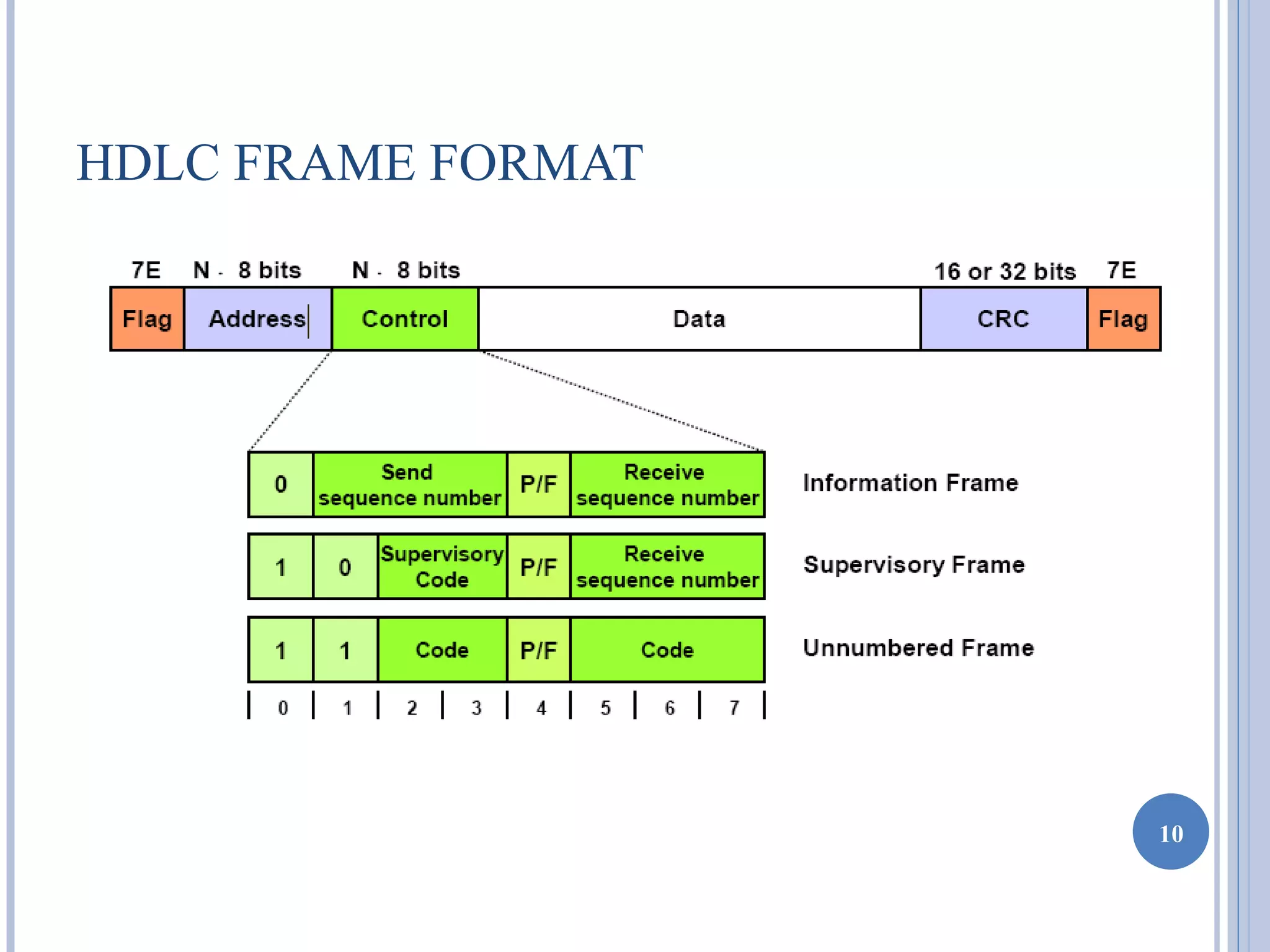
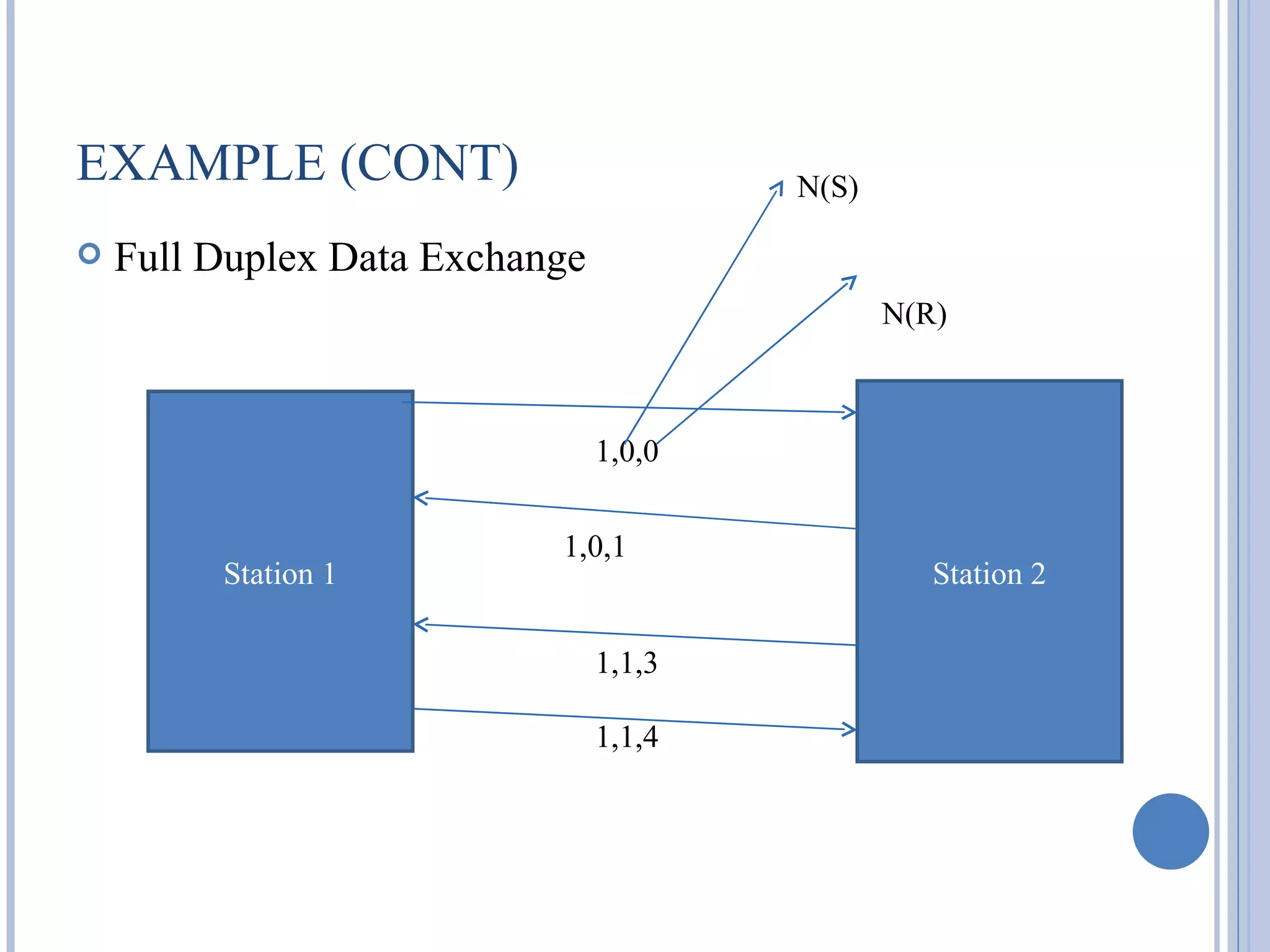
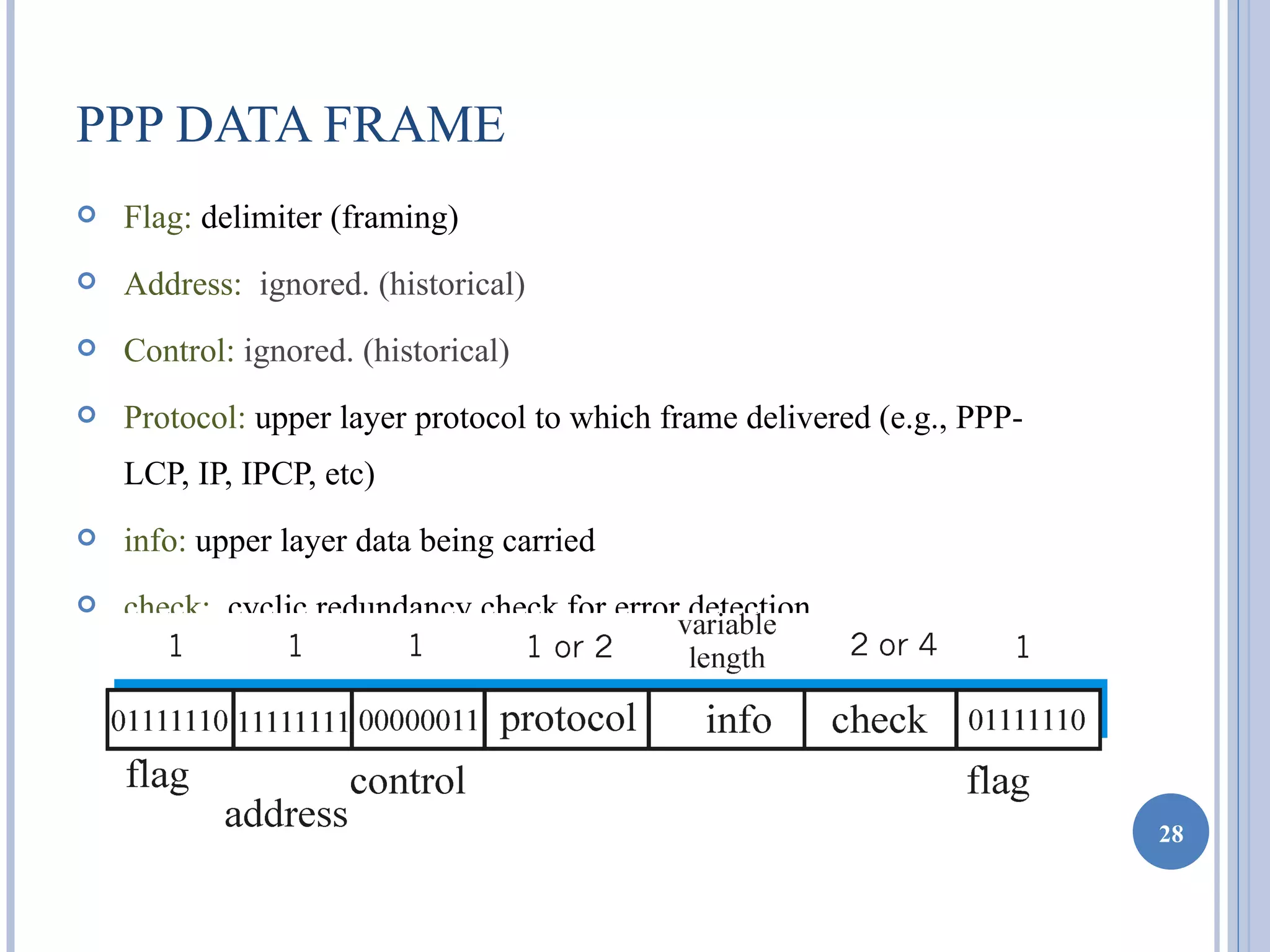


This document discusses several point-to-point data link protocols: HDLC, PPP, and SLIP. It provides an overview of HDLC, including its frame structure, operation, and applications. PPP is introduced as a successor to SLIP that adds functionality like authentication. The document also describes PPP's frame structure and use of link control and network control protocols.