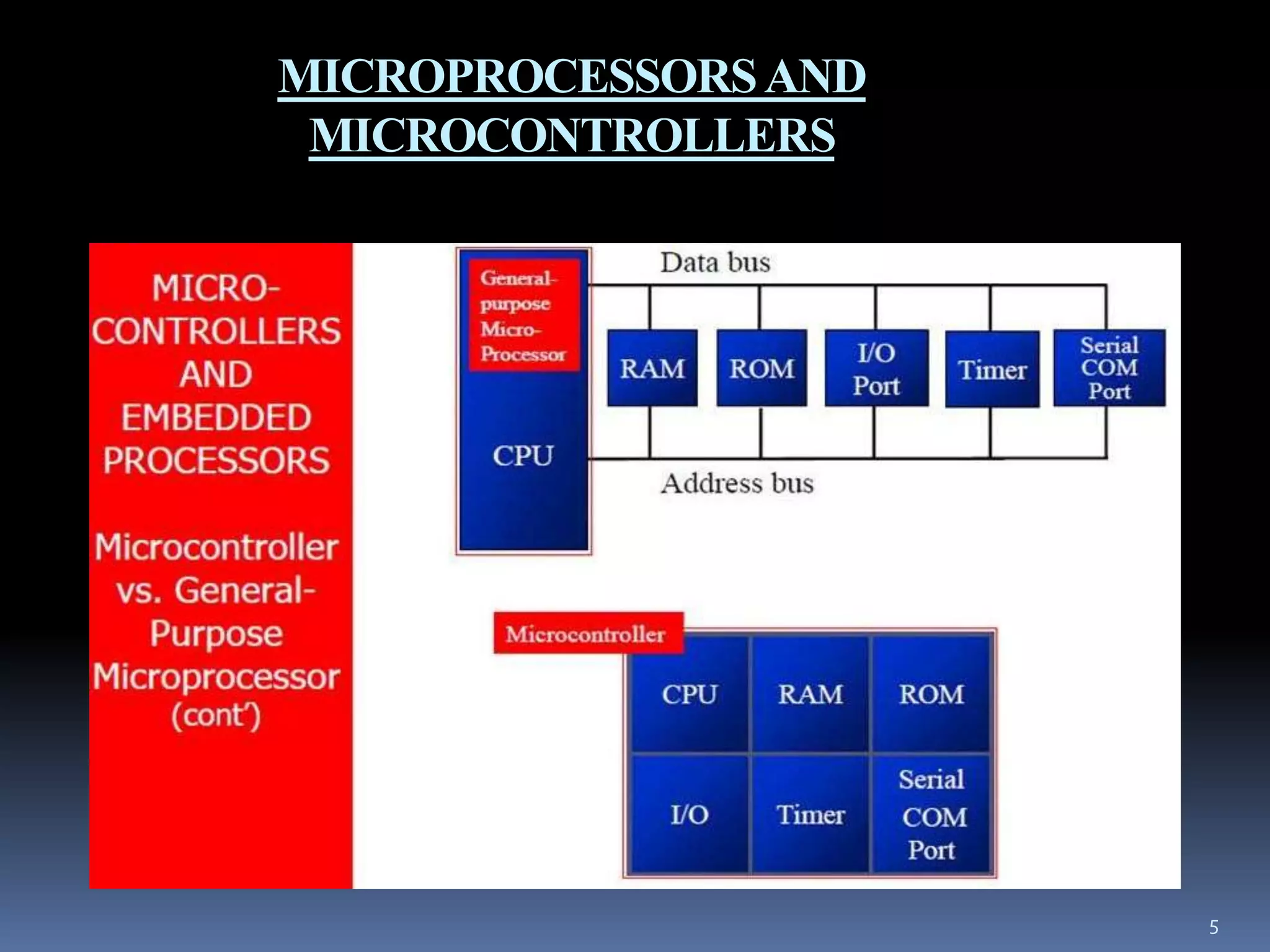
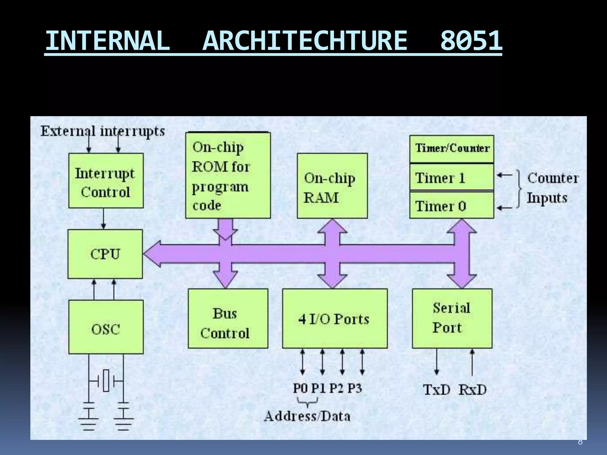
EMBEDDED SYSTEM
St. Margaret Engineering College
Neemrana (Rajasthan)
Submitted to:- Submitted by:-
Mr. Rohit Gupta Shilpa Kumari
Mr. Pavan Yadav (12ESMEC043)
1
What is embedded system ?
 A specialized computer system that is part of a
larger system or machine .
 Typically , an embedded system is housed on a
single microprocessor board with the program
stored in ROM.
Ex. :- Fridge , mobile phones etc.
 Embedded system include an operating system
, but may are so specialized that the entire
logic can be implanted as a single program.
2
3
In one sentence , we can say that , A special purpose
computer built into a larger device.
Any device that includes a programmable computer
but is not itself a general purpose computer.
The microprocessor is an embedded system is like an
electric motor in a washing machine.
MICROPROCESSORS AND MICROCONTROLLERS
In an embedded system,
the microcontrollers
ROM is burned with a
purpose for specific
functions needed for the
system. A printer is an
example of an
embedded system
because the processor
inside it performs one
task only;namely
getting the data and
printed it.
 On the other hand, a
PC can also load & run
software for a variety
of applications.
Because it has RAM
memory & an
operating system that
loads the application
software into RAM &
lets the CPU run it.
4
5
MICROPROCESSORSAND
MICROCONTROLLERS
APPLICATIONS
1. Signal processing system:- Real time video ,
DVD players, medical equipment.
2. Distributed control:- Network routers,
switches , elevators.
3. Small system:- mobile phones, smart cards,
MP3 players, digital converters, PC keyboard
and mouse.
6
ABOUT 8051
The 8051 microcontroller is first controller of MCS 51
family introduced by intel corporation at the end of
1970s.
Characteristics of 8051:-
 4k bytes ROM
 128 bytes RAM
 Two timer/counter(16 bit)
 A serial port
 4 parallel input output port
 Interrupt controller
The 8051 can address 64k bytes of external data memory
and 64k bytes of external program memory.
7
8
INTERNAL ARCHITECHTURE 8051
ARCHITECTURE
 Based on CISC and RISC
 CISC:- (complex instruction set controller)
 It invariably employ a microcode for
decoding the instructions and generate the
necessary control signals for performing the
intended operation.
 When an instruction is fetched from
memory, it is compared with the existing bit
pattern, when match is found it generates
the associated control signals to ALU and
registers.
9
10
 It takes good amount of time to decode the
meaning of complex instructions which perform
more than one operation.
 Also microcode requires more number of
transistors that are used in fabricating the CISC
architecture based processors.
RISC
 Reduced Instruction Set Controller.
 These are fast at numerical computations
required in science, graphics and engineering
applications.
 The total number of transistors used for the
design of RISC is half the number used in
CISC.
 This reduced number of transistors reduces the
power consumption.
11
COMPUTER ARCHITECTURE
 Depending on how external memory is
connected to the processors
 Von-Neumann machine.
 Harvard machine.
Von-Neumann machine:-
 It has 3 hardware subsystems; a CPU, a main
memory system and an I/O system.
 It uses stored program concept i.e. the
program and data are stored in the same
memory unit.
12
13
• It has a single path between the main memory
system and the control unit of the CPU. Because the
common path is used to access both the program as
well as the data, there is possibility of congestion on
the bus. This situation is called Von Neumann
Bottleneck.
 Harvard machine:-
 It uses separate memories for storing the program
and data.
 To connect these separate memories, it uses a
separate set of address, data and control lines.
14
 As separate memories and buses are used,
simultaneous access to the memory is possible
without any congestion over the bus, which in
turn increases the performances.
 It increases the cost of the system as separate
memories & separate buses are used.
PIN DIAGRAM OF 8051
15
Registers in 8051
 In CPU, registers are used to store information
temporarily. That information could be a byte of
data to be processed, or an address pointing to the
data to be fetched. 8051 have 8-bit registers.
16
17
 The most widely used registers are A
(accumulator), B, R0 -R7, DPTR (Data Pointer),
PC (Program Counter). All the registers except
DPTR and the program counter are 8 bits. DPTR
and PC are 16 bits.
ROBOTICS
A reprogrammable, multifunctional
manipulators designed to move material, parts
, tools or specialized devices through various
programmed motions for the performance of a
variety of task.
The word robotics was coined by American
science fiction writer Isaac Asimov first used
in 1942 in his short story “RUABOUT”. He
also proposed three laws of Robotics .
18
LAWS OF ROBOTICS
 A Robot may not injure a human being or
through inaction , allow a human being to
come to harm.
 A Robot must obey the orders given it by
human beings except where such orders
would conflict with the 1st and 2nd law.
 A Robot must protect its own existence as
long as such protection does not conflict with
the 1st and 2nd law.
19
AVR MICROCONTROLER
 Devices range from 1 to
256KB
 Pin count range from 8 to 100
 Full code compatibility
 Pin/feature compatible
families
 One set of development tools
20
OVERVIEW OF ATMEGA16
 The ATmega16 is a
low-power CMOS 8-bit
microcontroller based
on the AVR enhanced
RISC Architecture.
21
FEATURES OF ATMEGA16
 16 Kbytes of In-System Programmable Flash
 Program memory with Read-While-Write
capabilities
 512 bytes EEPROM, 1 Kbyte SRAM
 32general purpose I/O lines
 32 general purpose working registers
22
Continued…
 Write/Erase Cycles: 10,000 Flash/100,000
EEPROM
 Data retention: 20 years at 85°C/100 years at
25°C(1)
 Programming Lock for Software Security
 Up to 16 MIPS Throughput at 16 MHz
 512 Bytes EEPROM
23
PERIPHERAL FEATURES
 Two 8-bit Timer/Counters
 One 16-bit Timer/Counter
 Four PWM Channels
 8-channel, 10-bit ADC
24
ATMEGA16 PIN DIAGRAM
25
PIN DISCRIPTION
Atmega16 have total of 40 pins
32 I/O pins..
PORTA = 8 Pins
PORTB = 8 Pins
PORTC = 8 Pins
PORTD = 8 Pins
26
PIN DISCRIPTION
 VCC (PIN11) - Digital supply voltage.
 GND (PIN12) - Ground
27
PIN DISCRIPTION
 Port A (PA7..PA0) - Port A serves as the analog
inputs to the A/D Converter Port A also serves as
an 8-bit bi-directional I/O port, if the A/D
Converter is not used. Port pins can provide
internal pull-up resistors (selected for each bit)
 Port B (PB7..PB0) - Port B is an 8-bit bi-
directional I/O port with internal pull-up resistors
(selected for each bit). Port B also serves the
functions of various special features of the
ATmega16
28
ALTERNATE FUNCTION OF PORT A AND B :-
29
PIN DISCRIPTION
 Port C (PC7..PC0) - Port C is an 8-bit bi-
directional I/O port with internal pull-up resistors
(selected for each bit). If the JTAG interface is
enabled, the pull-up resistors on pins PC5(TDI),
PC3(TMS) and PC2(TCK) will be activated even
if a reset occurs
 Port D (PD7..PD0) - Port D is an 8-bit bi-
directional I/O port with internal pull-up resistors
(selected for each bit). Port D also serves the
functions of various special features of the
ATmega16
30
ALTERNATE FUNCTION OF PORT C AND D:-
31
PIN DISCRIPTION
 RESET - Reset Input. A low level on this pin for
longer than the minimum pulse length will
generate a reset. Shorter pulses are not guaranteed
to generate a reset.
AVCC - AVCC is the supply voltage pin for Port
A and the A/D Converter. It should be externally
connected to VCC, even if the ADC is not used. If
the ADC is used, it should be connected to VCC
through a low-pass filter.
• AREF - AREF is the analog reference pin for the
A/D Converter.
32
REFERENCES
1. http://mathcs.slu.edu/~fritts/CSCI305_306_F0
8/AVR/AVR%20Introduction.pdf
2. http://www.circuitstoday.com/microcontroller-
invention-history
3. http://www.atmel.com/products/microcontroll
ers/avr/
4. http://www.circuitstoday.com/basics-of-
microcontrollers
33
34

embedded system and microcontroller

  • 1.
    EMBEDDED SYSTEM St. MargaretEngineering College Neemrana (Rajasthan) Submitted to:- Submitted by:- Mr. Rohit Gupta Shilpa Kumari Mr. Pavan Yadav (12ESMEC043) 1
  • 2.
    What is embeddedsystem ?  A specialized computer system that is part of a larger system or machine .  Typically , an embedded system is housed on a single microprocessor board with the program stored in ROM. Ex. :- Fridge , mobile phones etc.  Embedded system include an operating system , but may are so specialized that the entire logic can be implanted as a single program. 2
  • 3.
    3 In one sentence, we can say that , A special purpose computer built into a larger device. Any device that includes a programmable computer but is not itself a general purpose computer. The microprocessor is an embedded system is like an electric motor in a washing machine.
  • 4.
    MICROPROCESSORS AND MICROCONTROLLERS Inan embedded system, the microcontrollers ROM is burned with a purpose for specific functions needed for the system. A printer is an example of an embedded system because the processor inside it performs one task only;namely getting the data and printed it.  On the other hand, a PC can also load & run software for a variety of applications. Because it has RAM memory & an operating system that loads the application software into RAM & lets the CPU run it. 4
  • 5.
  • 6.
    APPLICATIONS 1. Signal processingsystem:- Real time video , DVD players, medical equipment. 2. Distributed control:- Network routers, switches , elevators. 3. Small system:- mobile phones, smart cards, MP3 players, digital converters, PC keyboard and mouse. 6
  • 7.
    ABOUT 8051 The 8051microcontroller is first controller of MCS 51 family introduced by intel corporation at the end of 1970s. Characteristics of 8051:-  4k bytes ROM  128 bytes RAM  Two timer/counter(16 bit)  A serial port  4 parallel input output port  Interrupt controller The 8051 can address 64k bytes of external data memory and 64k bytes of external program memory. 7
  • 8.
  • 9.
    ARCHITECTURE  Based onCISC and RISC  CISC:- (complex instruction set controller)  It invariably employ a microcode for decoding the instructions and generate the necessary control signals for performing the intended operation.  When an instruction is fetched from memory, it is compared with the existing bit pattern, when match is found it generates the associated control signals to ALU and registers. 9
  • 10.
    10  It takesgood amount of time to decode the meaning of complex instructions which perform more than one operation.  Also microcode requires more number of transistors that are used in fabricating the CISC architecture based processors.
  • 11.
    RISC  Reduced InstructionSet Controller.  These are fast at numerical computations required in science, graphics and engineering applications.  The total number of transistors used for the design of RISC is half the number used in CISC.  This reduced number of transistors reduces the power consumption. 11
  • 12.
    COMPUTER ARCHITECTURE  Dependingon how external memory is connected to the processors  Von-Neumann machine.  Harvard machine. Von-Neumann machine:-  It has 3 hardware subsystems; a CPU, a main memory system and an I/O system.  It uses stored program concept i.e. the program and data are stored in the same memory unit. 12
  • 13.
    13 • It hasa single path between the main memory system and the control unit of the CPU. Because the common path is used to access both the program as well as the data, there is possibility of congestion on the bus. This situation is called Von Neumann Bottleneck.  Harvard machine:-  It uses separate memories for storing the program and data.  To connect these separate memories, it uses a separate set of address, data and control lines.
  • 14.
    14  As separatememories and buses are used, simultaneous access to the memory is possible without any congestion over the bus, which in turn increases the performances.  It increases the cost of the system as separate memories & separate buses are used.
  • 15.
  • 16.
    Registers in 8051 In CPU, registers are used to store information temporarily. That information could be a byte of data to be processed, or an address pointing to the data to be fetched. 8051 have 8-bit registers. 16
  • 17.
    17  The mostwidely used registers are A (accumulator), B, R0 -R7, DPTR (Data Pointer), PC (Program Counter). All the registers except DPTR and the program counter are 8 bits. DPTR and PC are 16 bits.
  • 18.
    ROBOTICS A reprogrammable, multifunctional manipulatorsdesigned to move material, parts , tools or specialized devices through various programmed motions for the performance of a variety of task. The word robotics was coined by American science fiction writer Isaac Asimov first used in 1942 in his short story “RUABOUT”. He also proposed three laws of Robotics . 18
  • 19.
    LAWS OF ROBOTICS A Robot may not injure a human being or through inaction , allow a human being to come to harm.  A Robot must obey the orders given it by human beings except where such orders would conflict with the 1st and 2nd law.  A Robot must protect its own existence as long as such protection does not conflict with the 1st and 2nd law. 19
  • 20.
    AVR MICROCONTROLER  Devicesrange from 1 to 256KB  Pin count range from 8 to 100  Full code compatibility  Pin/feature compatible families  One set of development tools 20
  • 21.
    OVERVIEW OF ATMEGA16 The ATmega16 is a low-power CMOS 8-bit microcontroller based on the AVR enhanced RISC Architecture. 21
  • 22.
    FEATURES OF ATMEGA16 16 Kbytes of In-System Programmable Flash  Program memory with Read-While-Write capabilities  512 bytes EEPROM, 1 Kbyte SRAM  32general purpose I/O lines  32 general purpose working registers 22
  • 23.
    Continued…  Write/Erase Cycles:10,000 Flash/100,000 EEPROM  Data retention: 20 years at 85°C/100 years at 25°C(1)  Programming Lock for Software Security  Up to 16 MIPS Throughput at 16 MHz  512 Bytes EEPROM 23
  • 24.
    PERIPHERAL FEATURES  Two8-bit Timer/Counters  One 16-bit Timer/Counter  Four PWM Channels  8-channel, 10-bit ADC 24
  • 25.
  • 26.
    PIN DISCRIPTION Atmega16 havetotal of 40 pins 32 I/O pins.. PORTA = 8 Pins PORTB = 8 Pins PORTC = 8 Pins PORTD = 8 Pins 26
  • 27.
    PIN DISCRIPTION  VCC(PIN11) - Digital supply voltage.  GND (PIN12) - Ground 27
  • 28.
    PIN DISCRIPTION  PortA (PA7..PA0) - Port A serves as the analog inputs to the A/D Converter Port A also serves as an 8-bit bi-directional I/O port, if the A/D Converter is not used. Port pins can provide internal pull-up resistors (selected for each bit)  Port B (PB7..PB0) - Port B is an 8-bit bi- directional I/O port with internal pull-up resistors (selected for each bit). Port B also serves the functions of various special features of the ATmega16 28
  • 29.
    ALTERNATE FUNCTION OFPORT A AND B :- 29
  • 30.
    PIN DISCRIPTION  PortC (PC7..PC0) - Port C is an 8-bit bi- directional I/O port with internal pull-up resistors (selected for each bit). If the JTAG interface is enabled, the pull-up resistors on pins PC5(TDI), PC3(TMS) and PC2(TCK) will be activated even if a reset occurs  Port D (PD7..PD0) - Port D is an 8-bit bi- directional I/O port with internal pull-up resistors (selected for each bit). Port D also serves the functions of various special features of the ATmega16 30
  • 31.
    ALTERNATE FUNCTION OFPORT C AND D:- 31
  • 32.
    PIN DISCRIPTION  RESET- Reset Input. A low level on this pin for longer than the minimum pulse length will generate a reset. Shorter pulses are not guaranteed to generate a reset. AVCC - AVCC is the supply voltage pin for Port A and the A/D Converter. It should be externally connected to VCC, even if the ADC is not used. If the ADC is used, it should be connected to VCC through a low-pass filter. • AREF - AREF is the analog reference pin for the A/D Converter. 32
  • 33.
    REFERENCES 1. http://mathcs.slu.edu/~fritts/CSCI305_306_F0 8/AVR/AVR%20Introduction.pdf 2. http://www.circuitstoday.com/microcontroller- invention-history 3.http://www.atmel.com/products/microcontroll ers/avr/ 4. http://www.circuitstoday.com/basics-of- microcontrollers 33
  • 34.