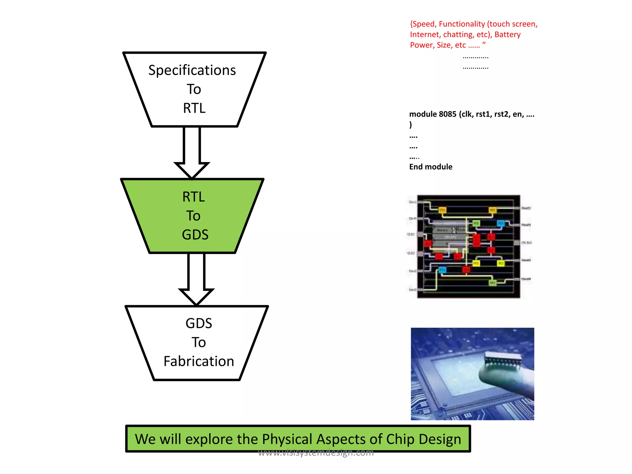
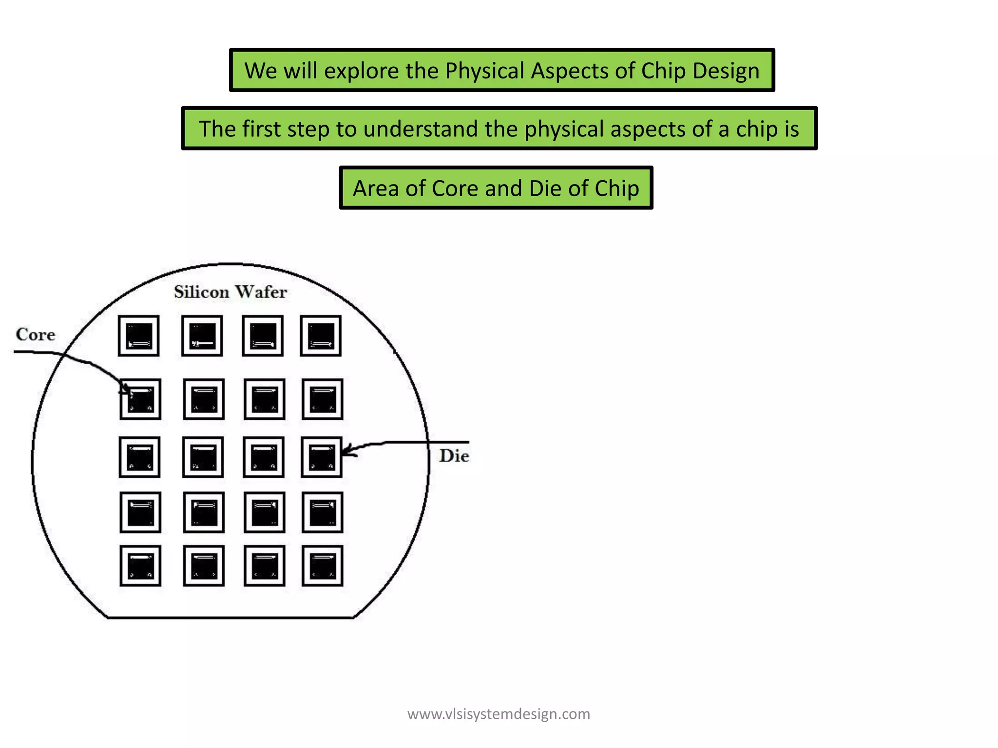
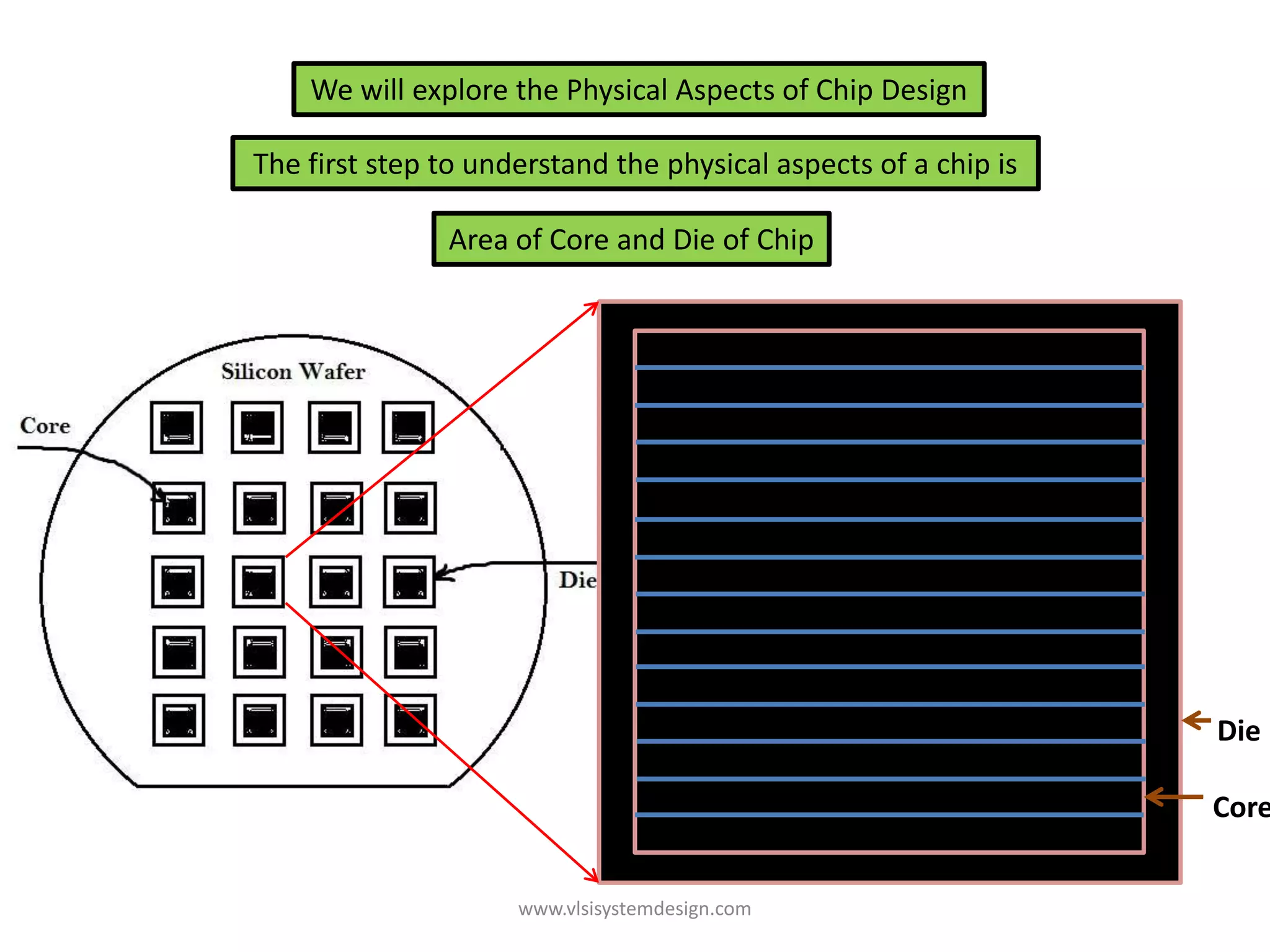
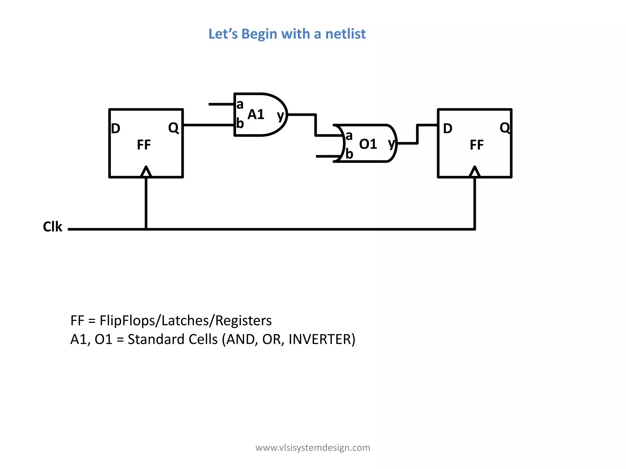
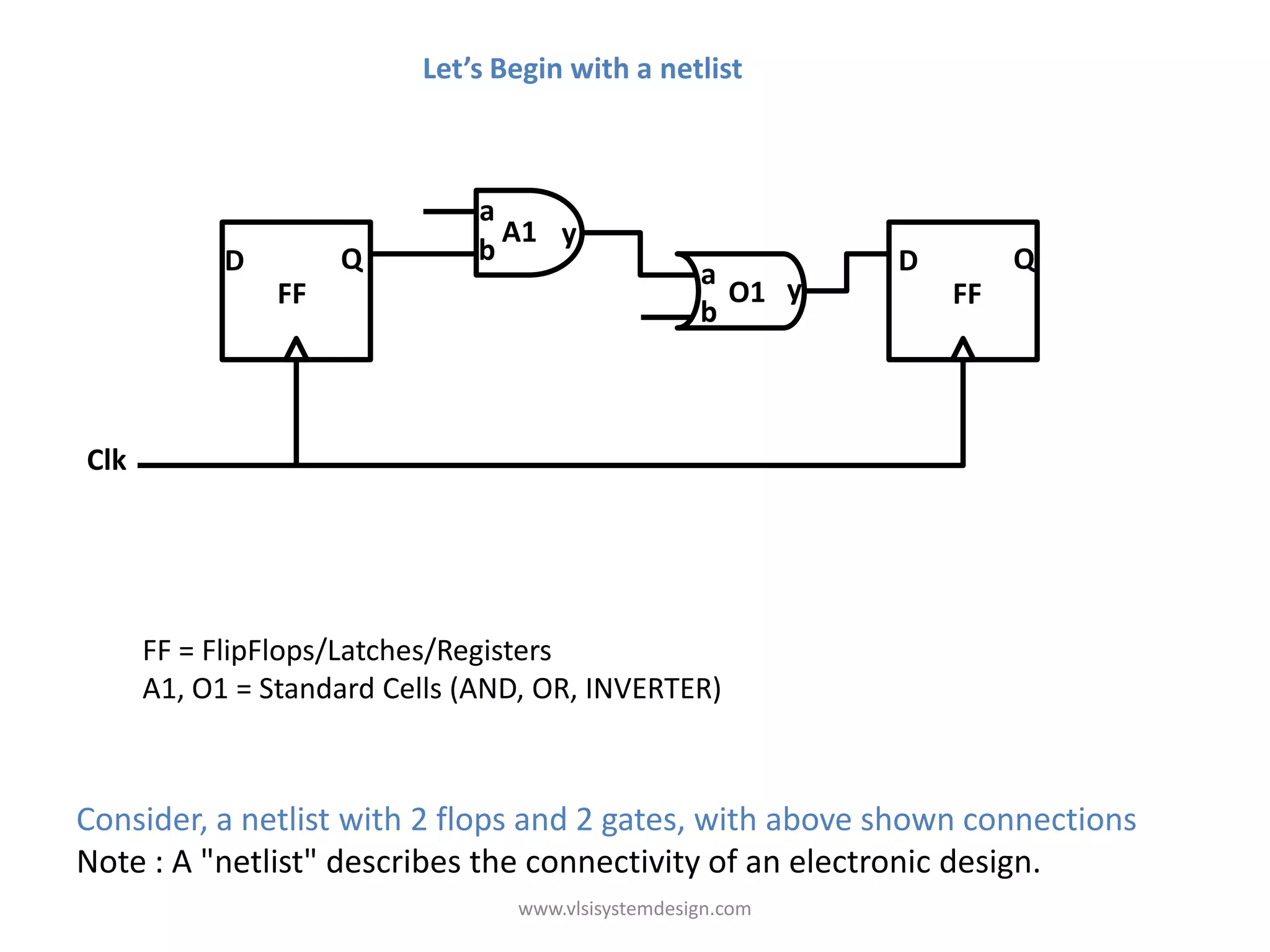
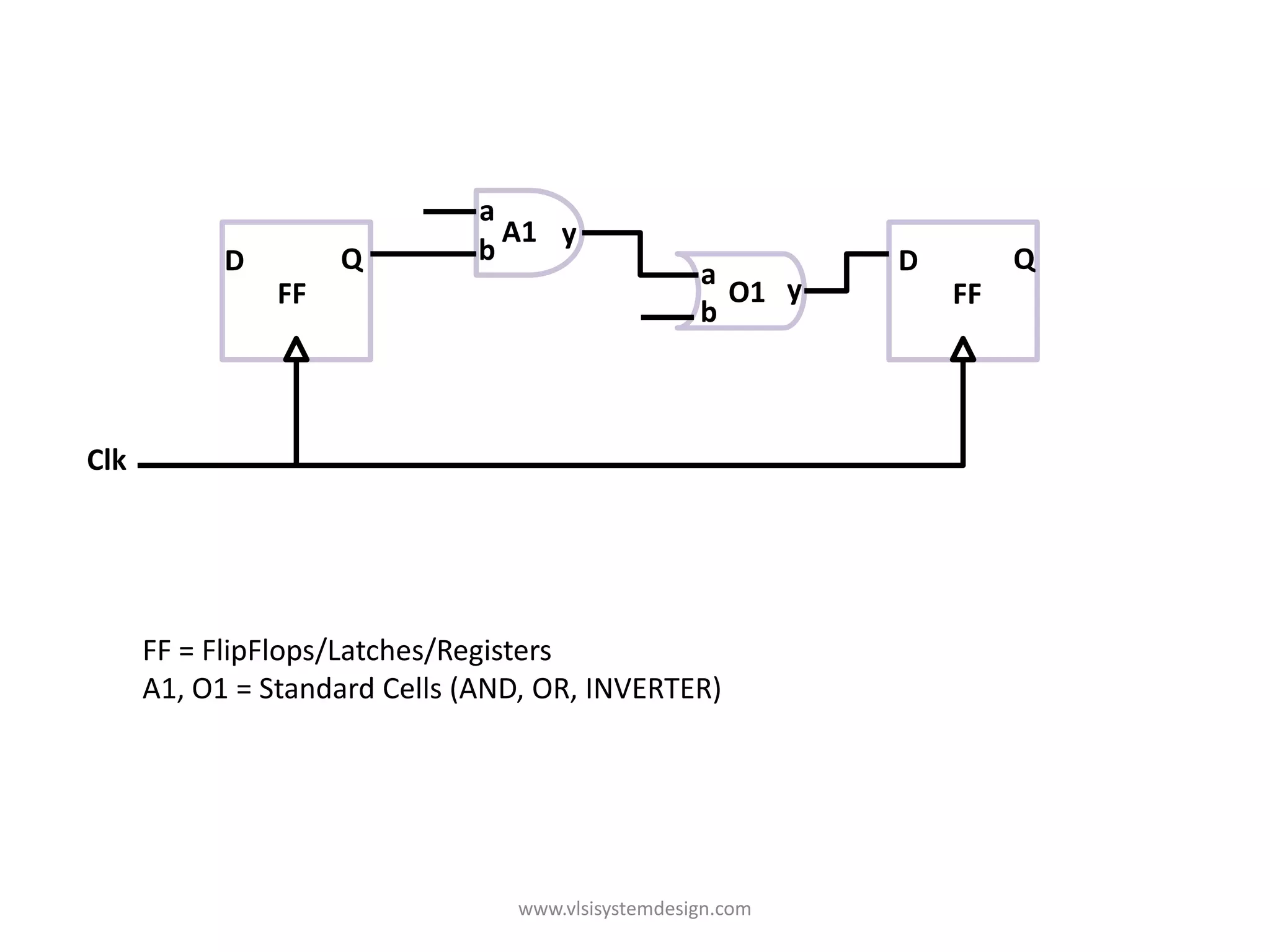
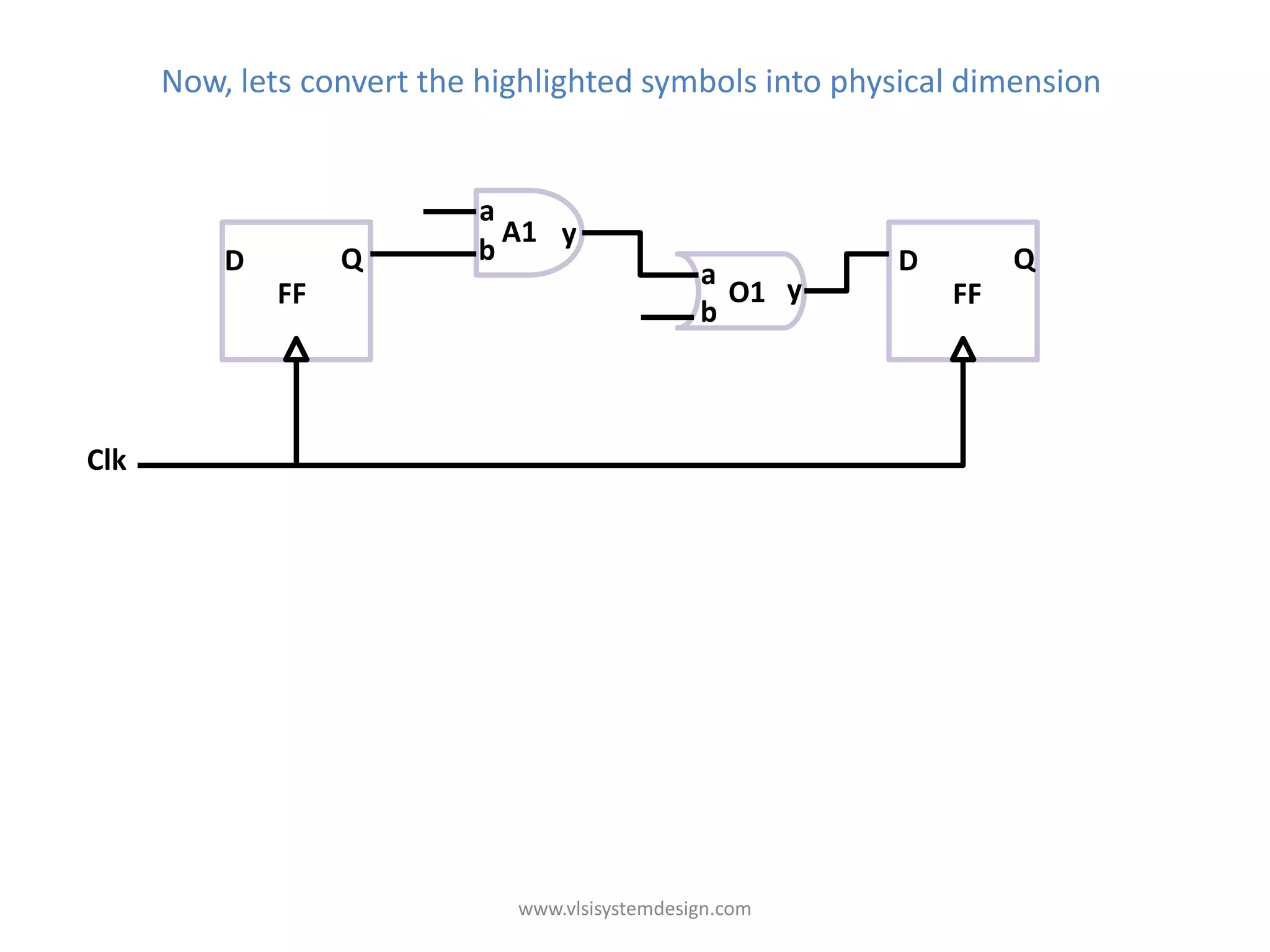
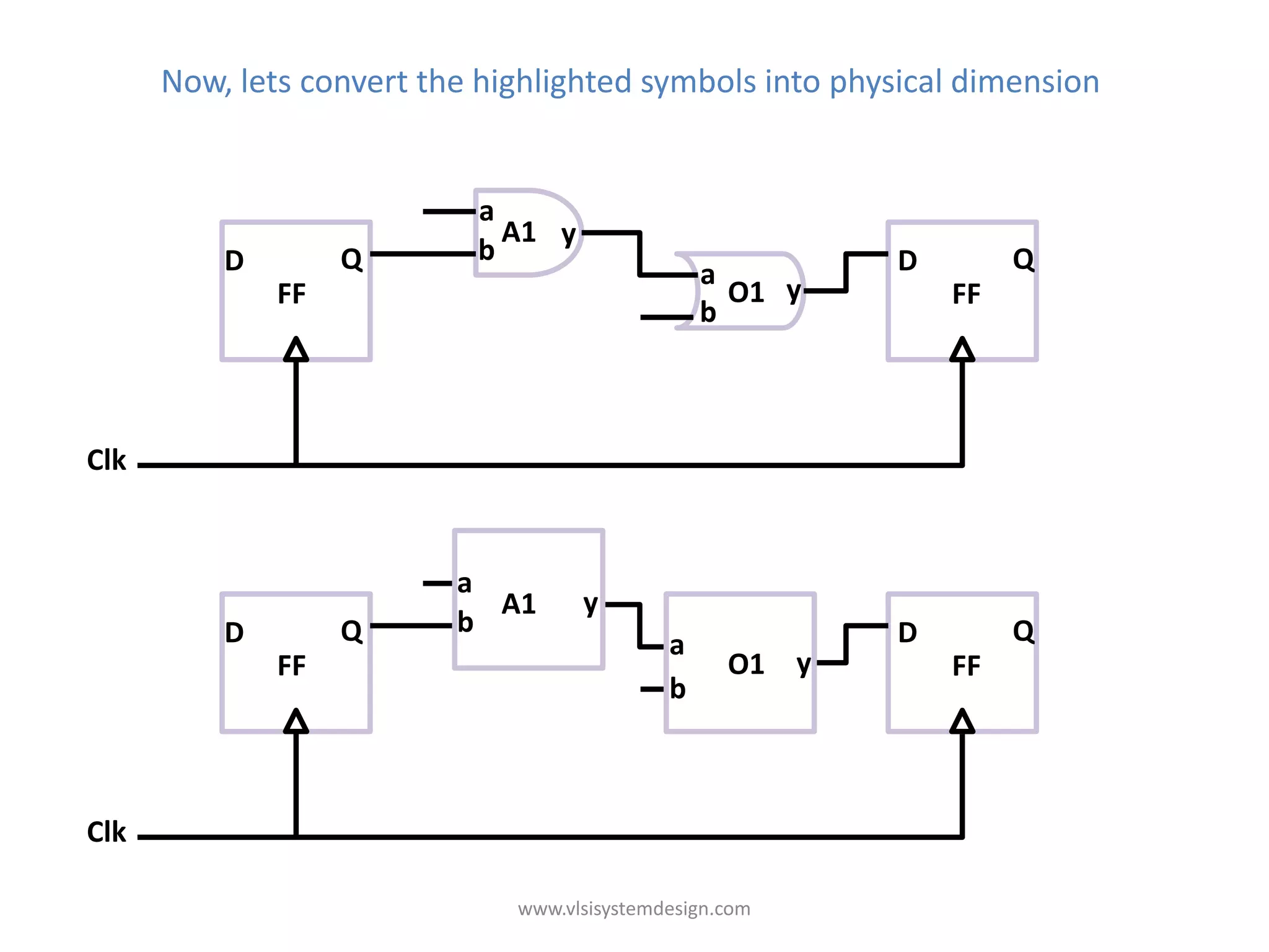
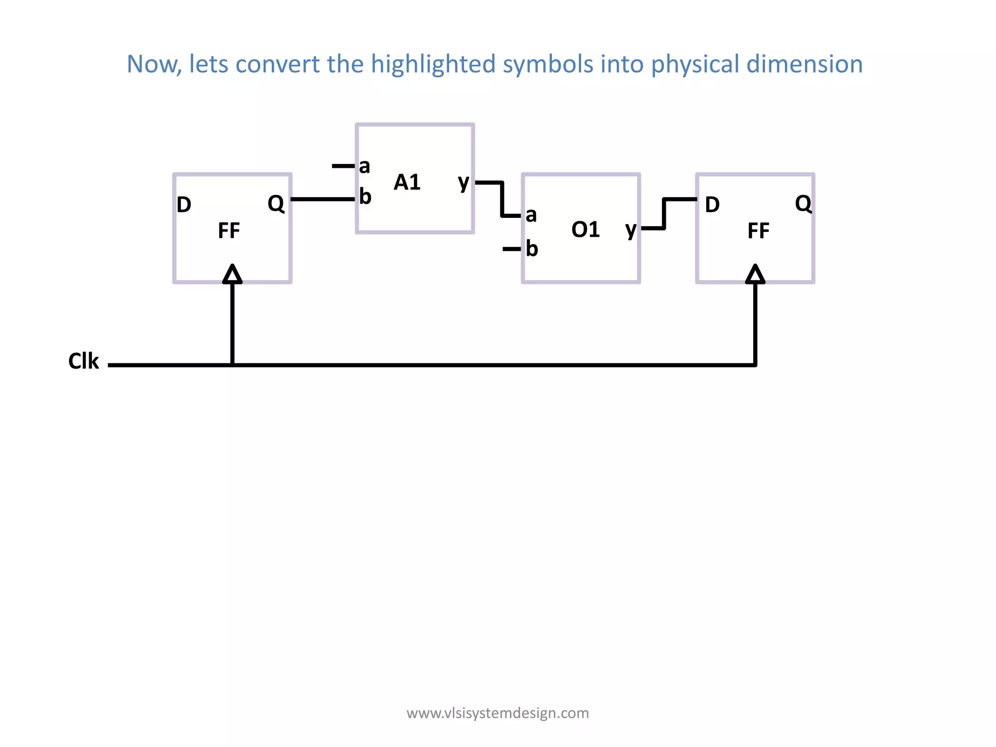
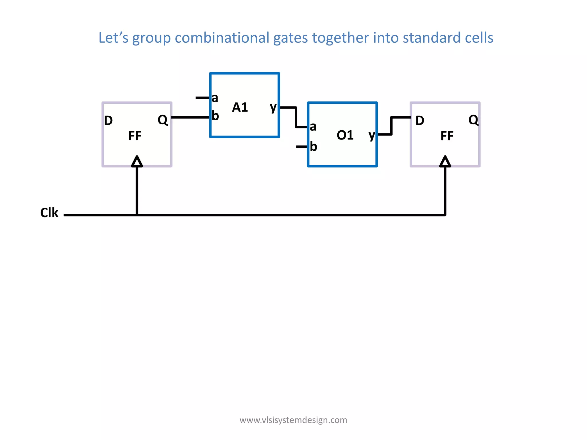
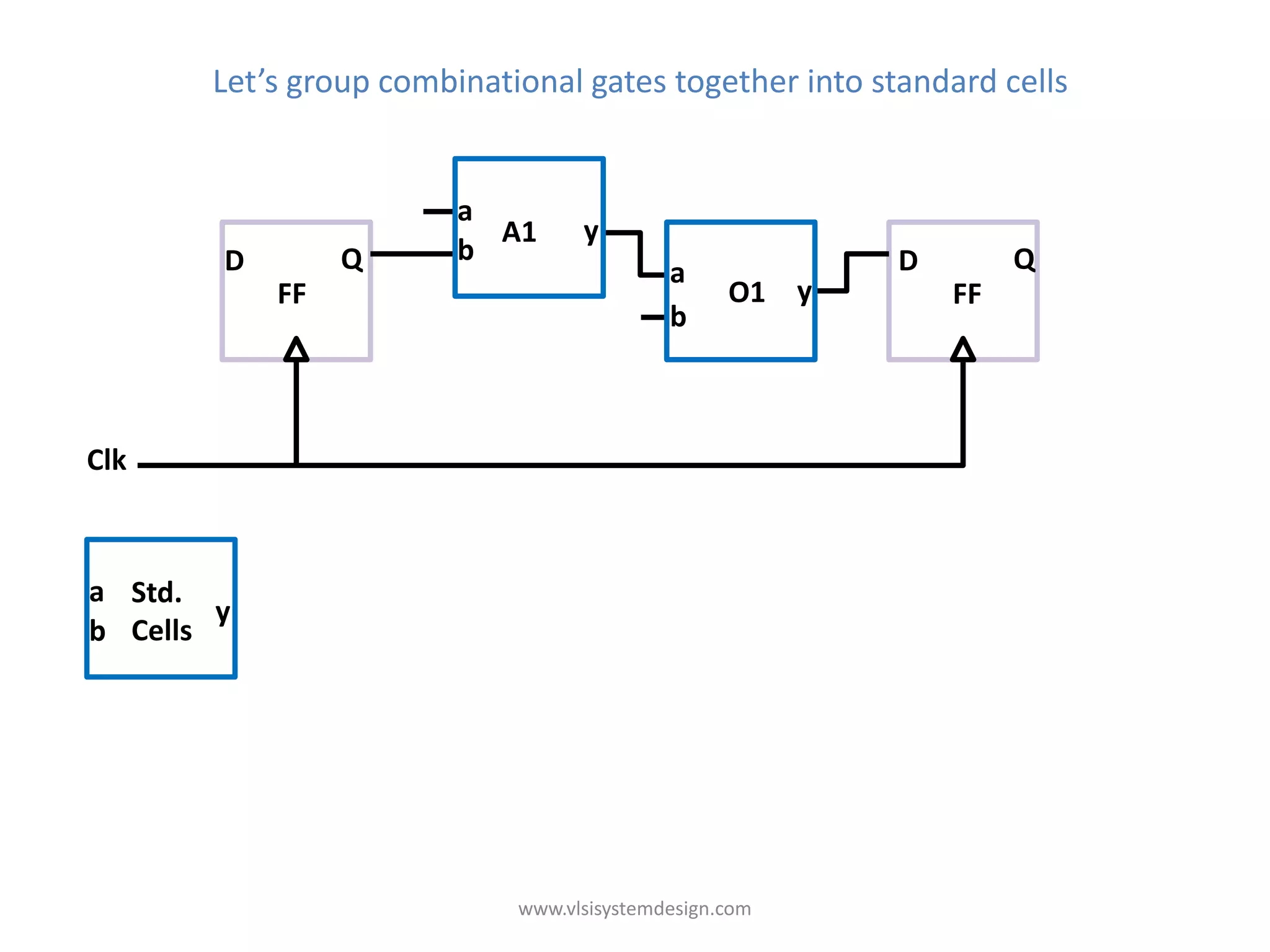
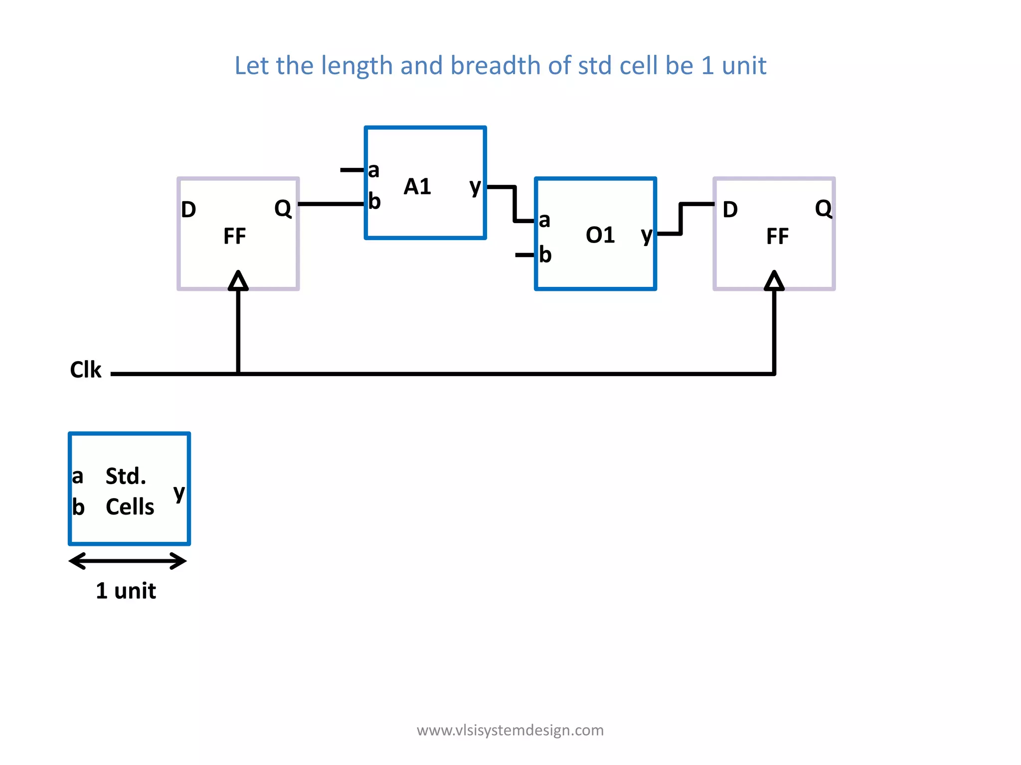
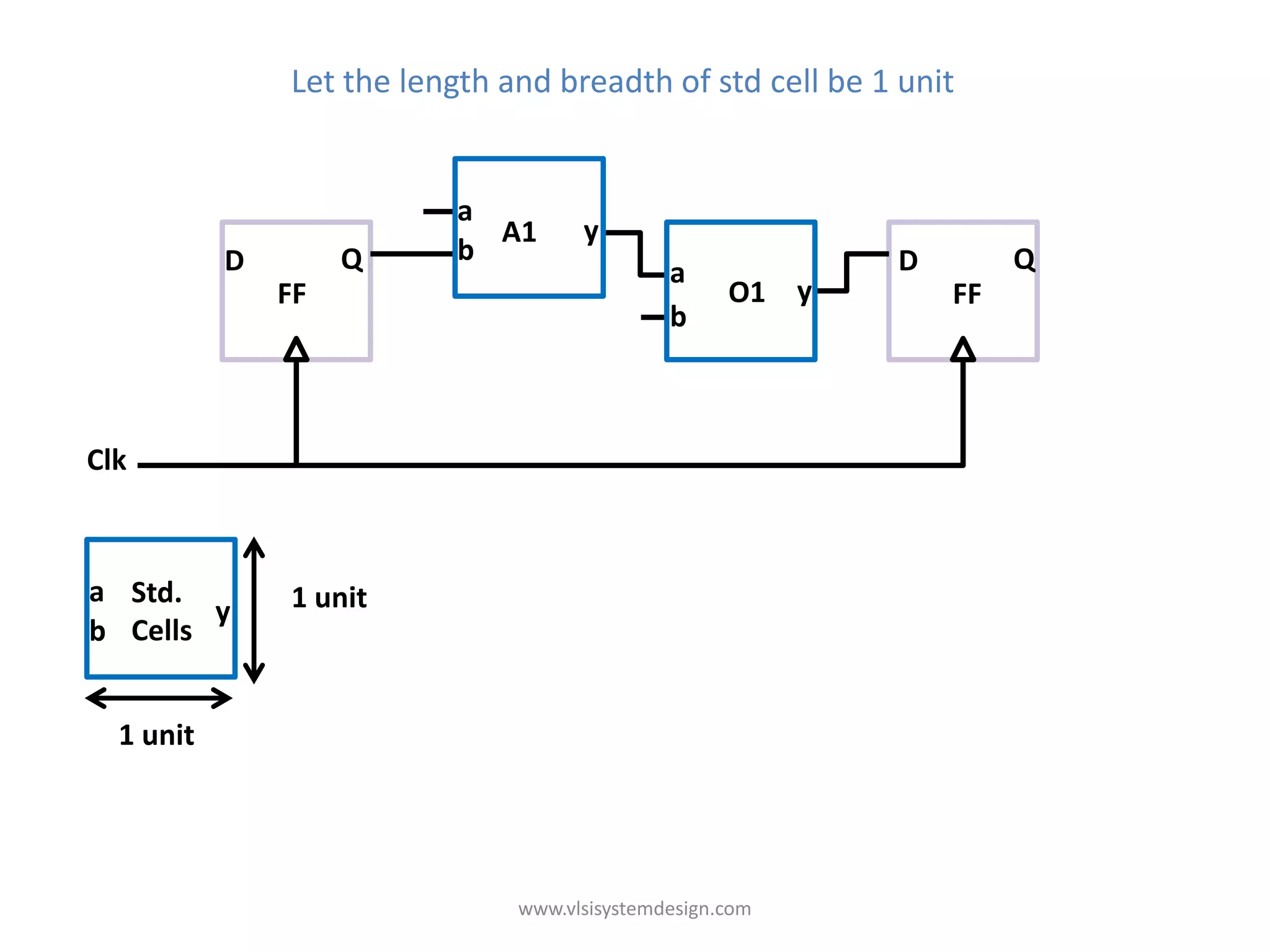
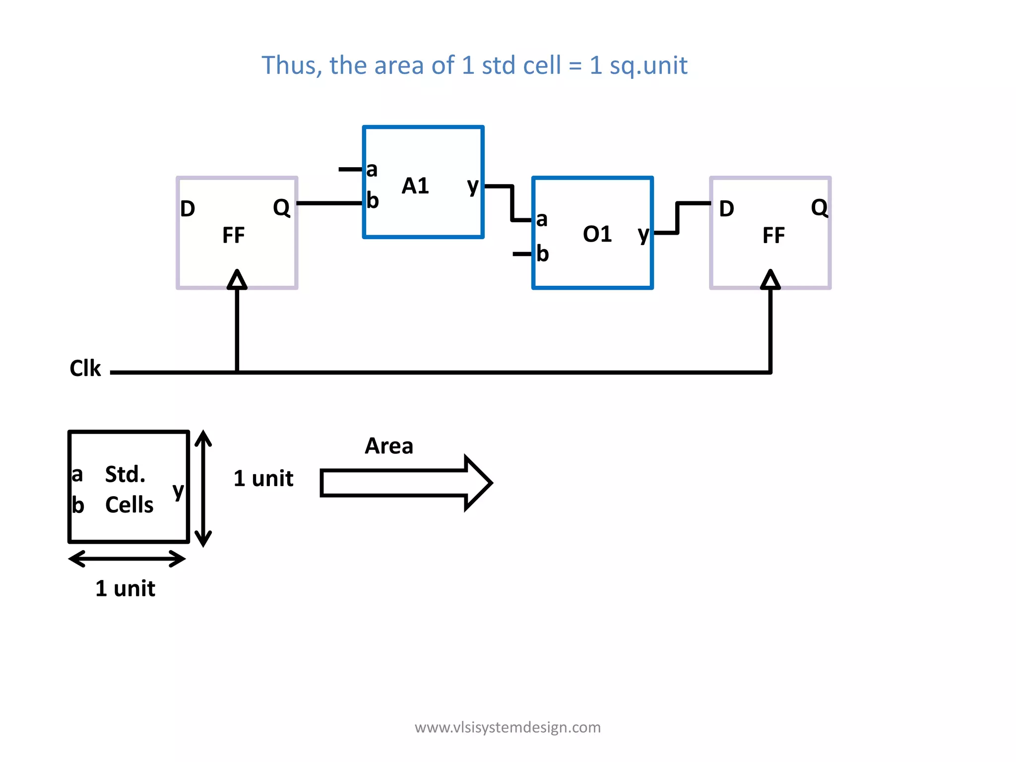
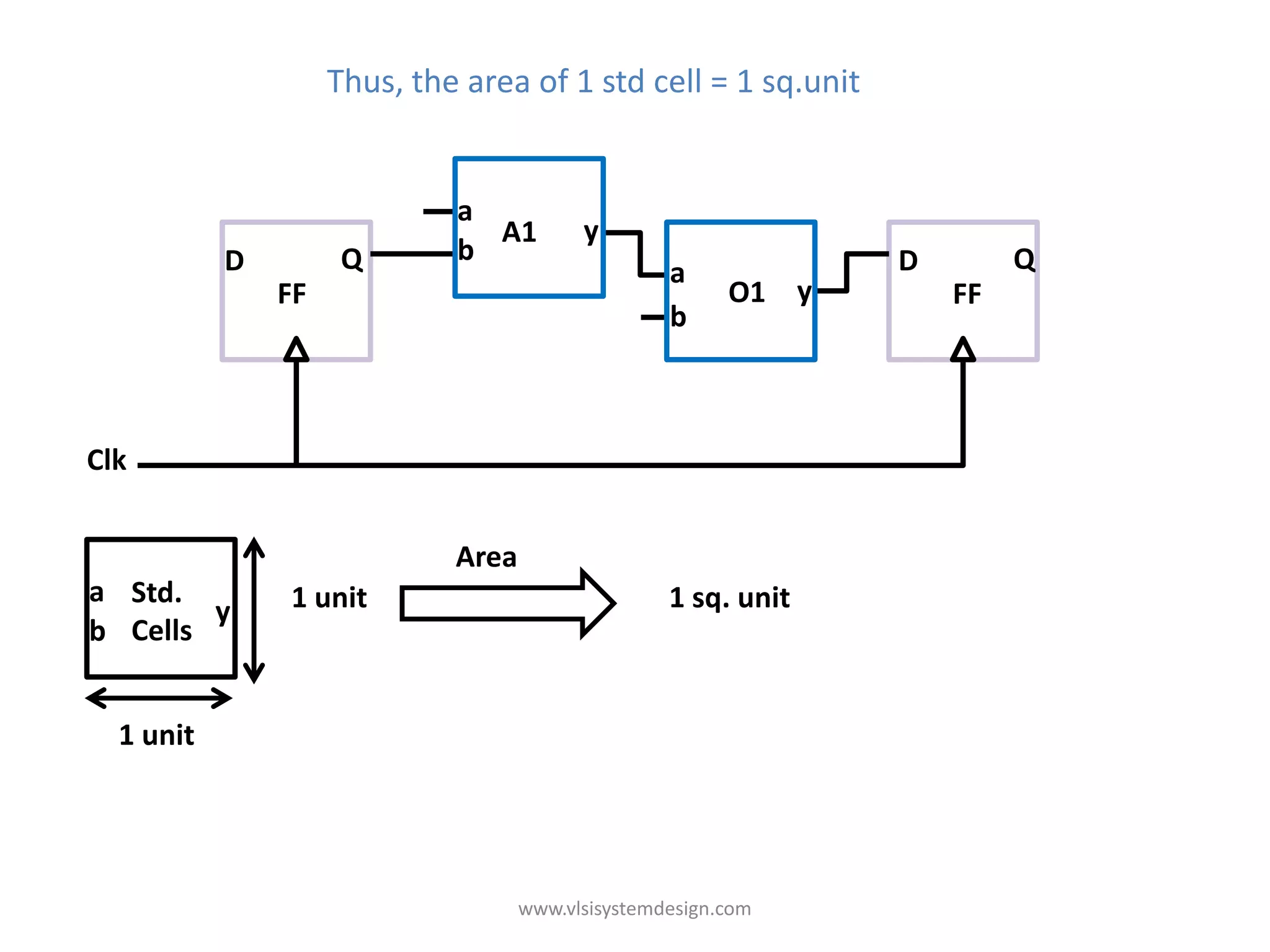
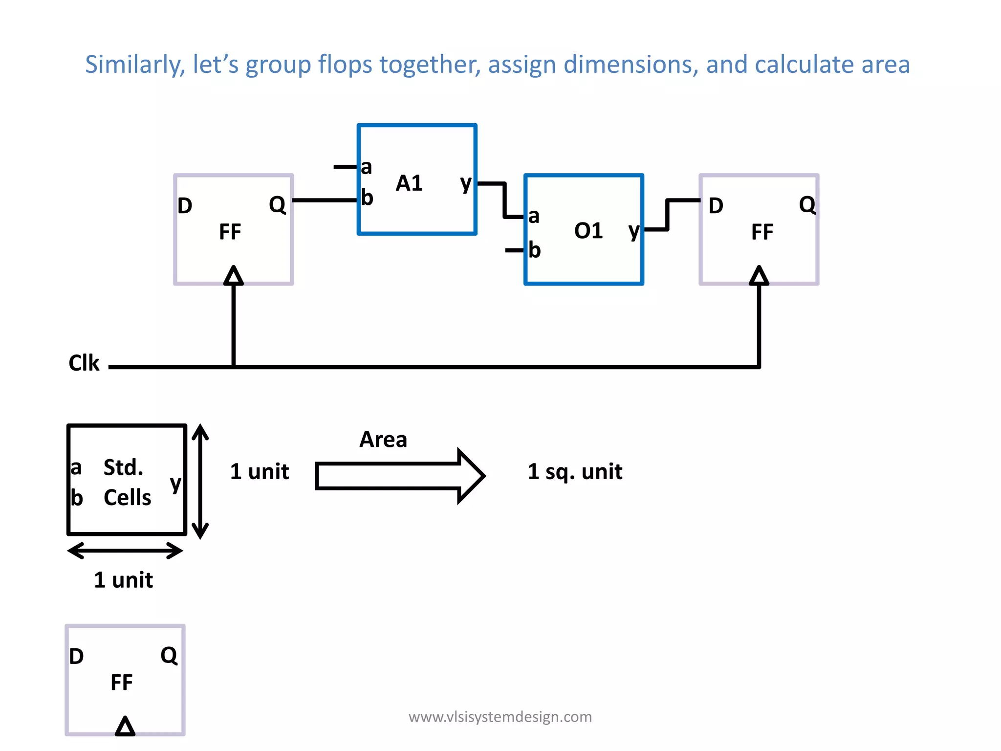
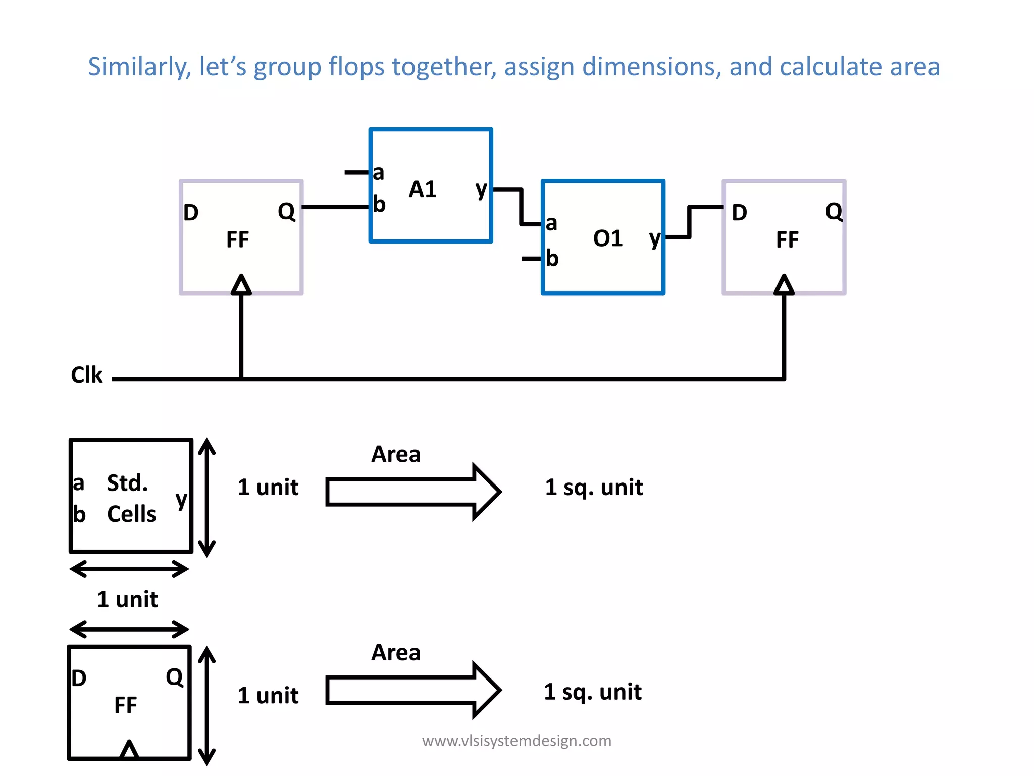
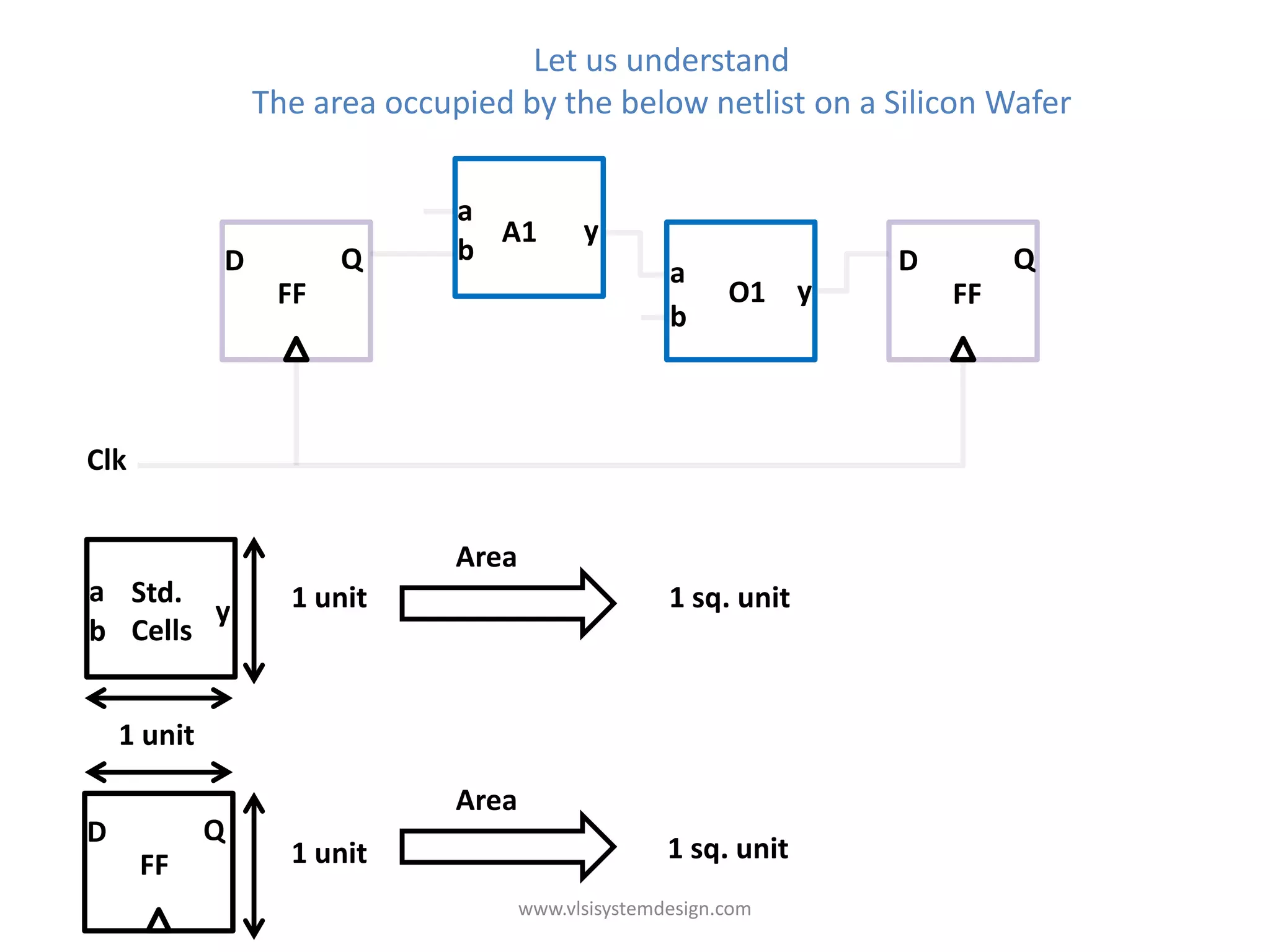
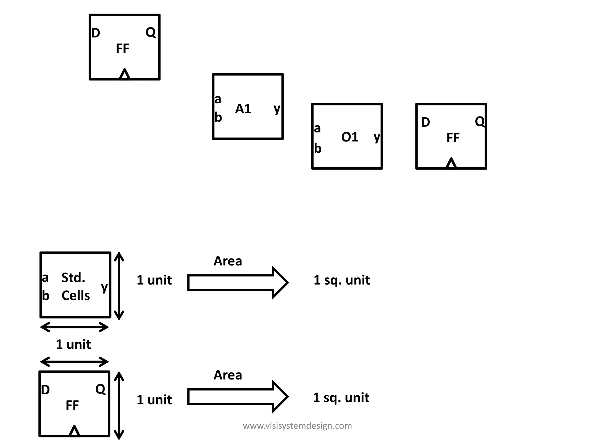
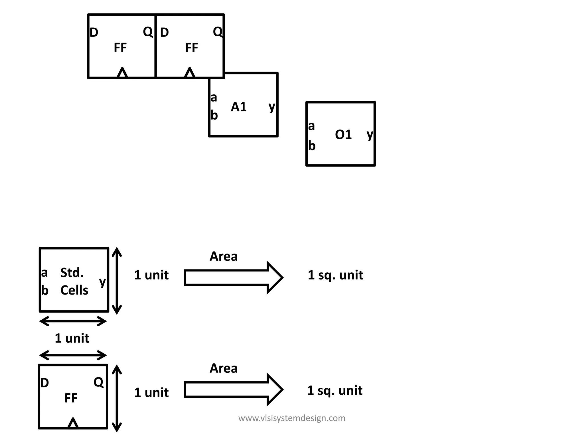
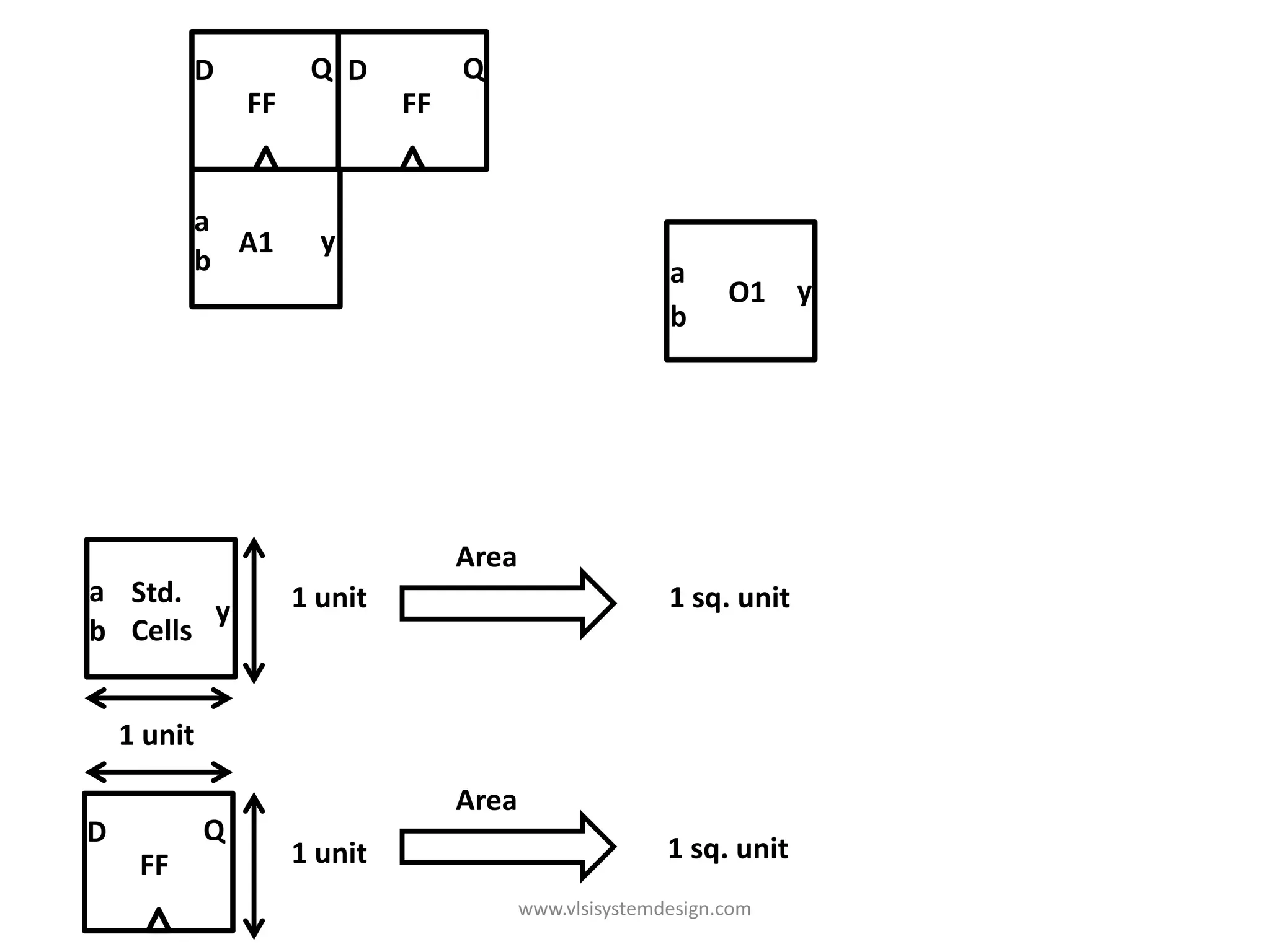
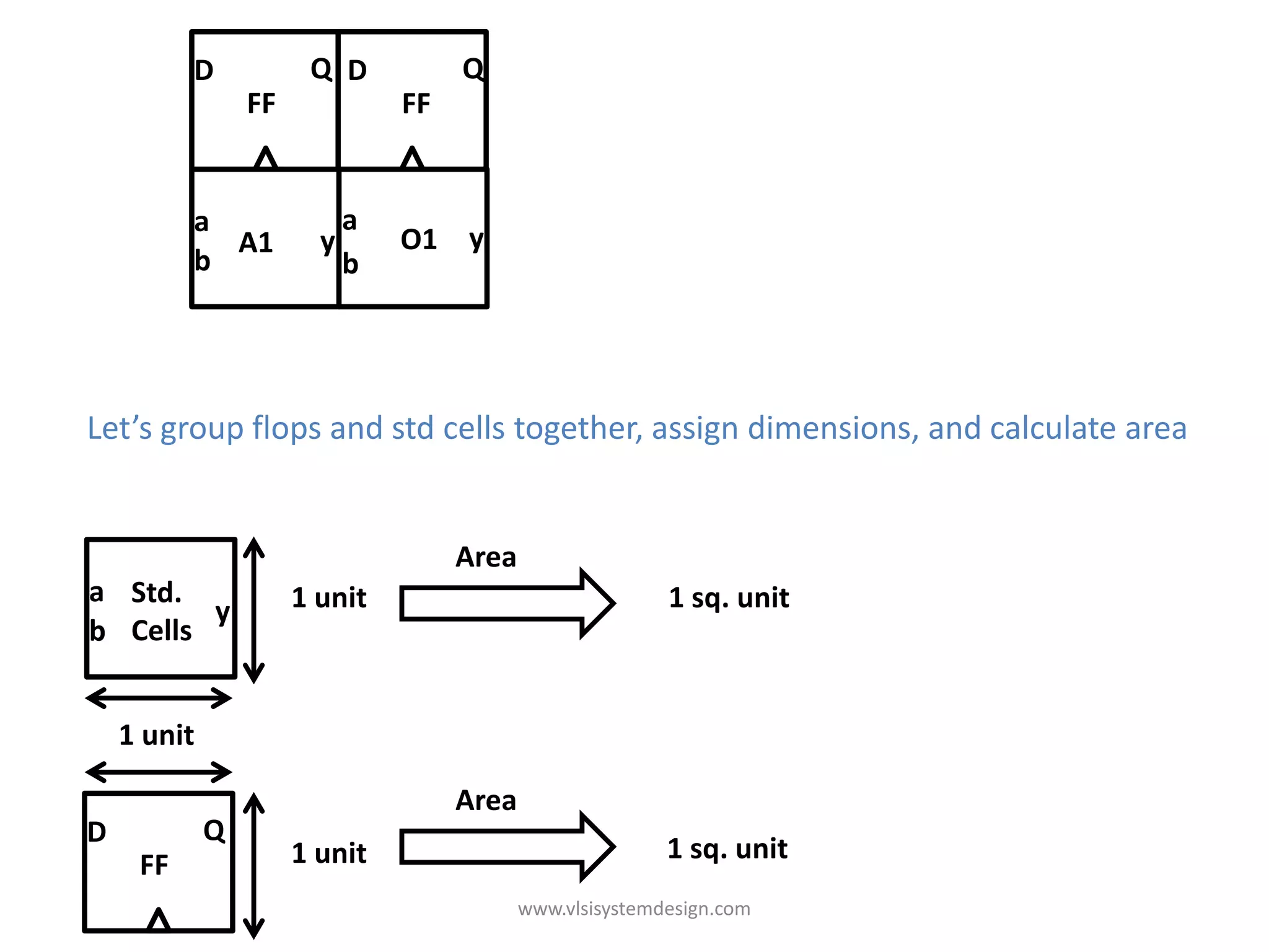
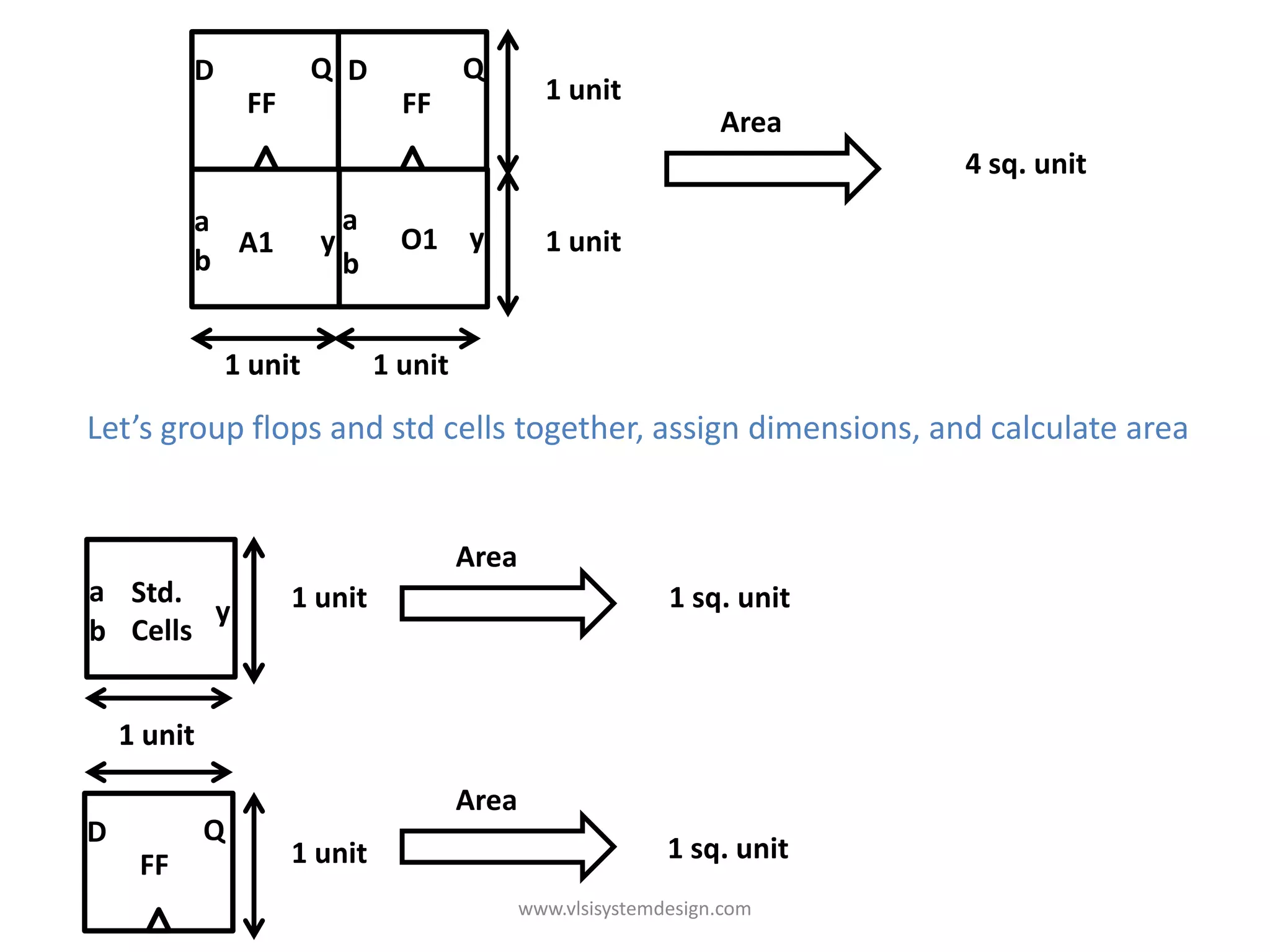
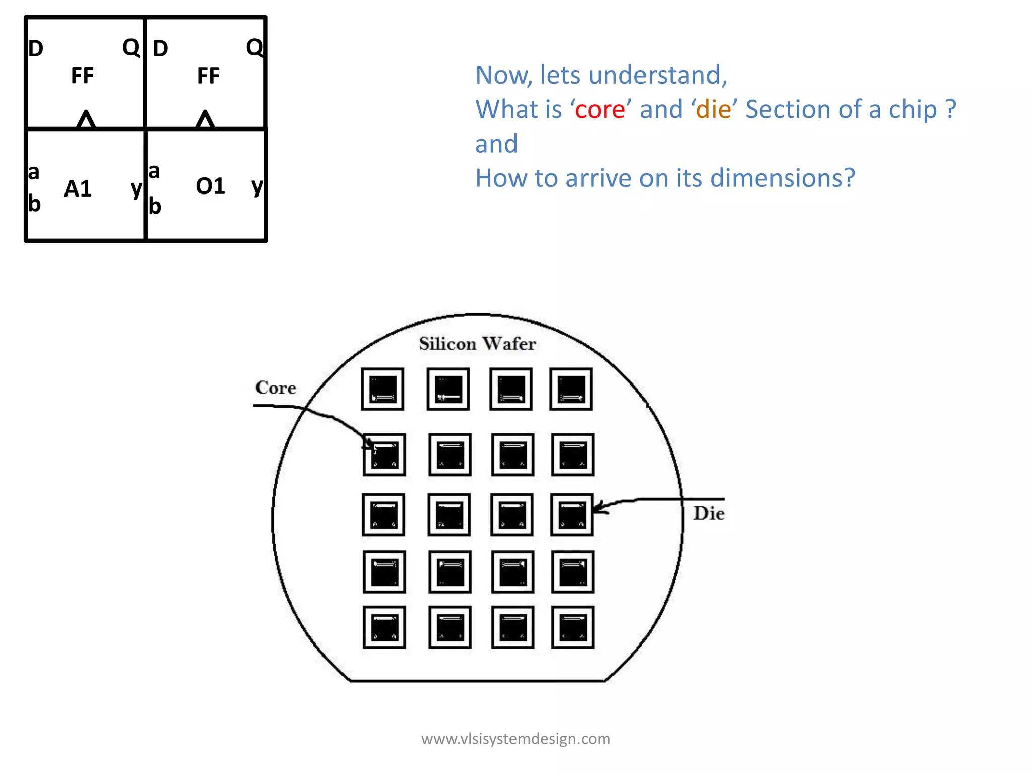
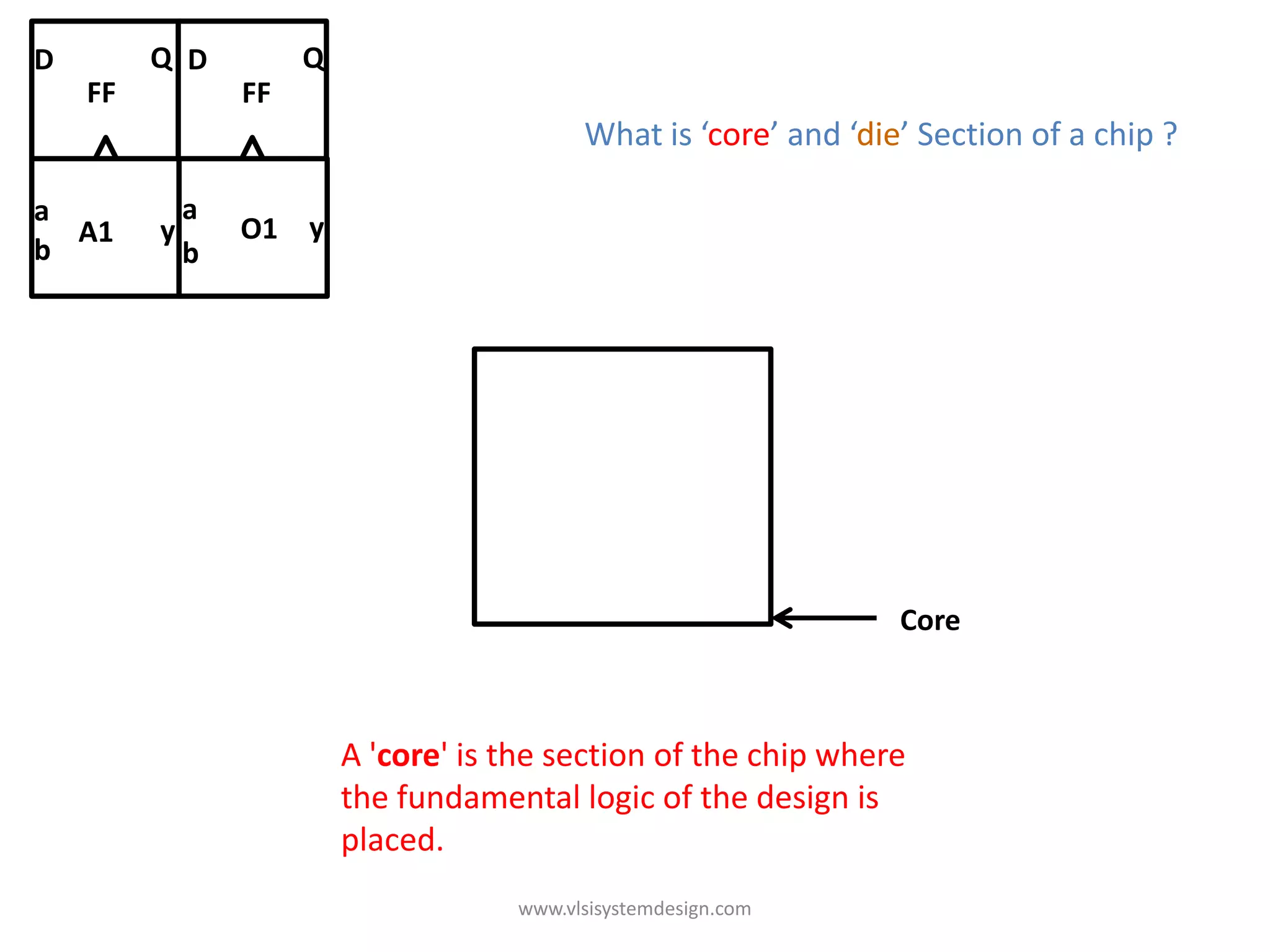
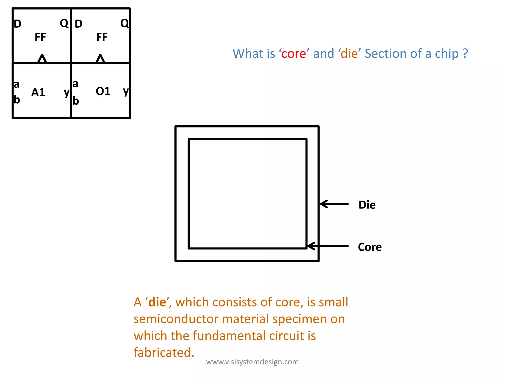
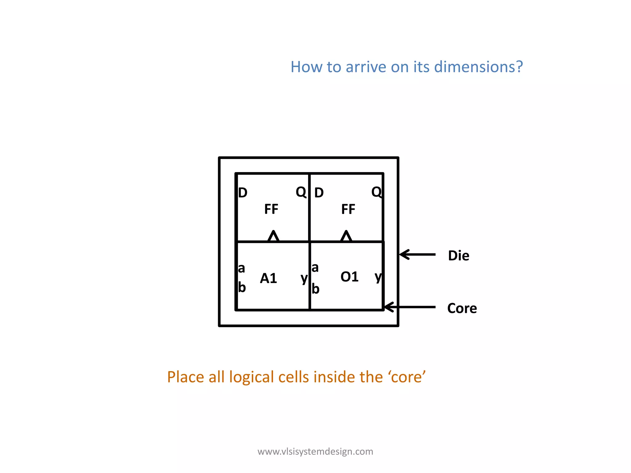
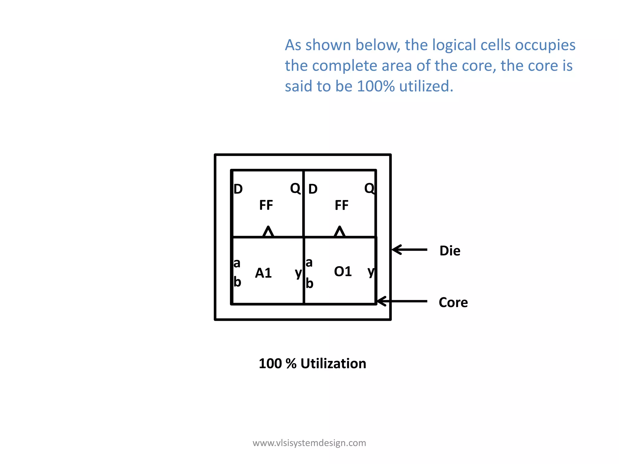
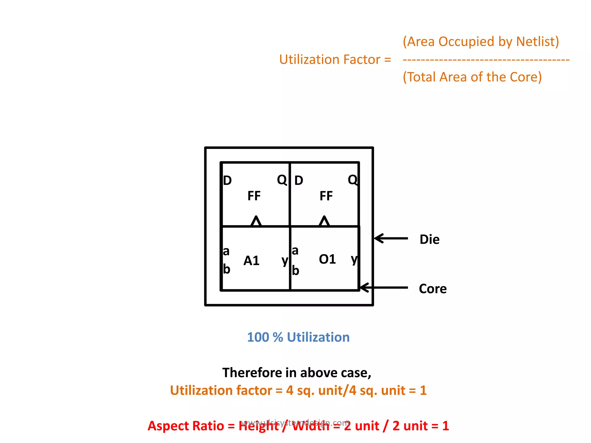
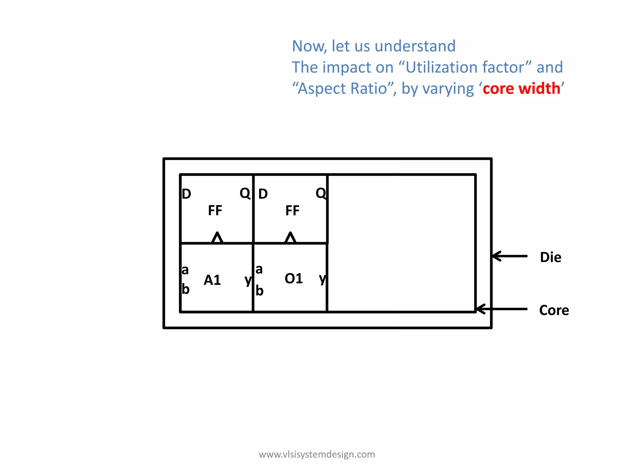
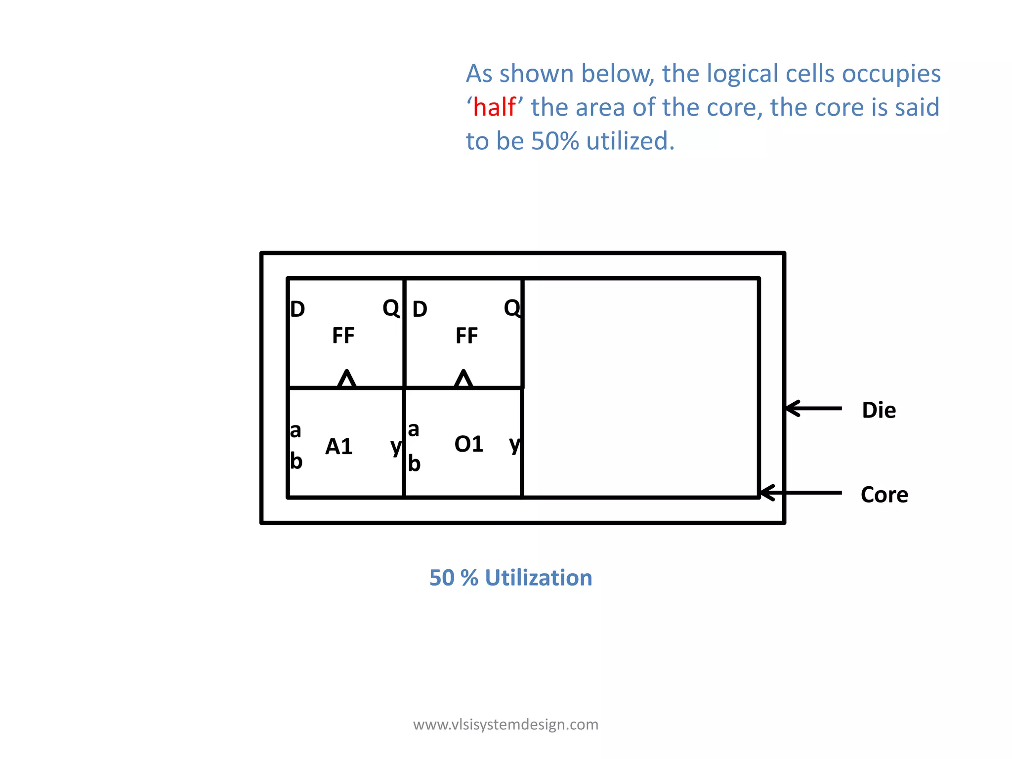
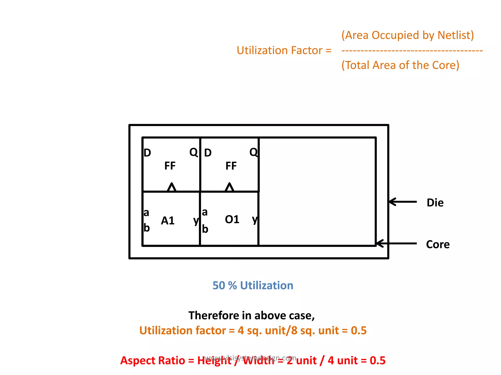
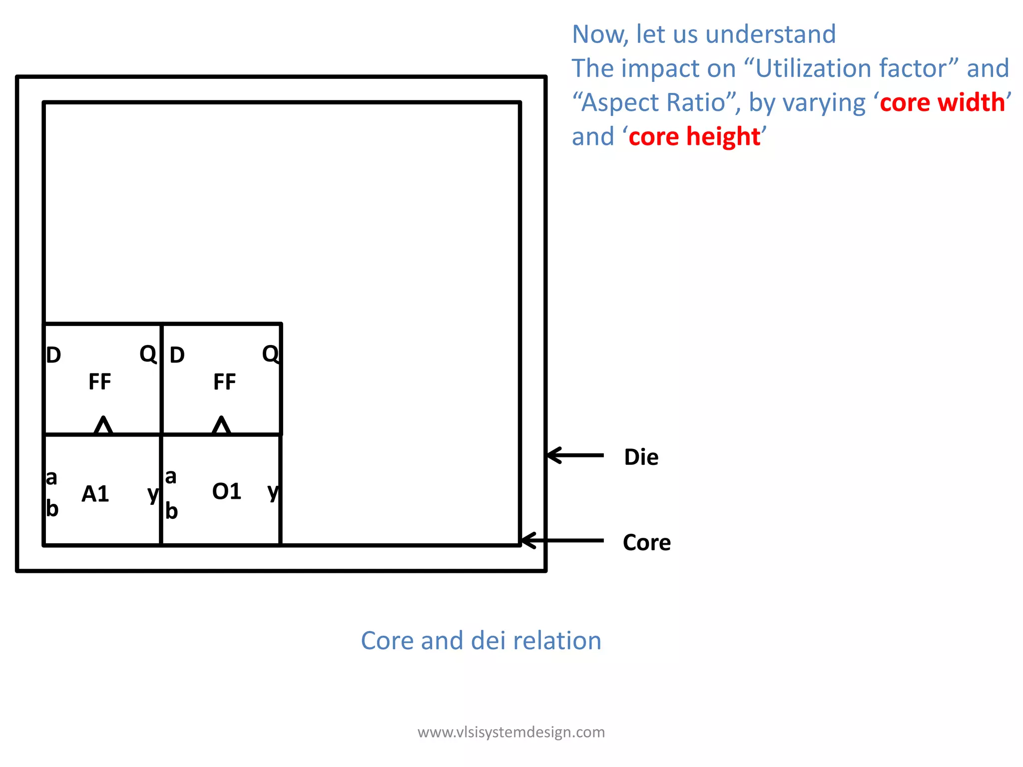
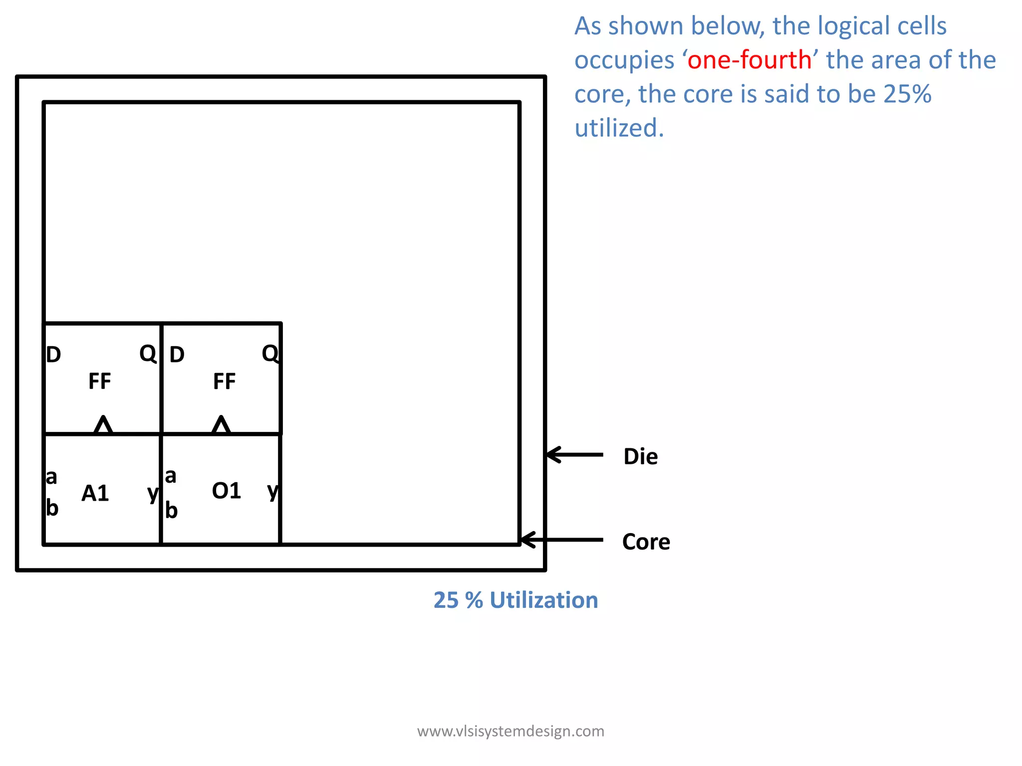
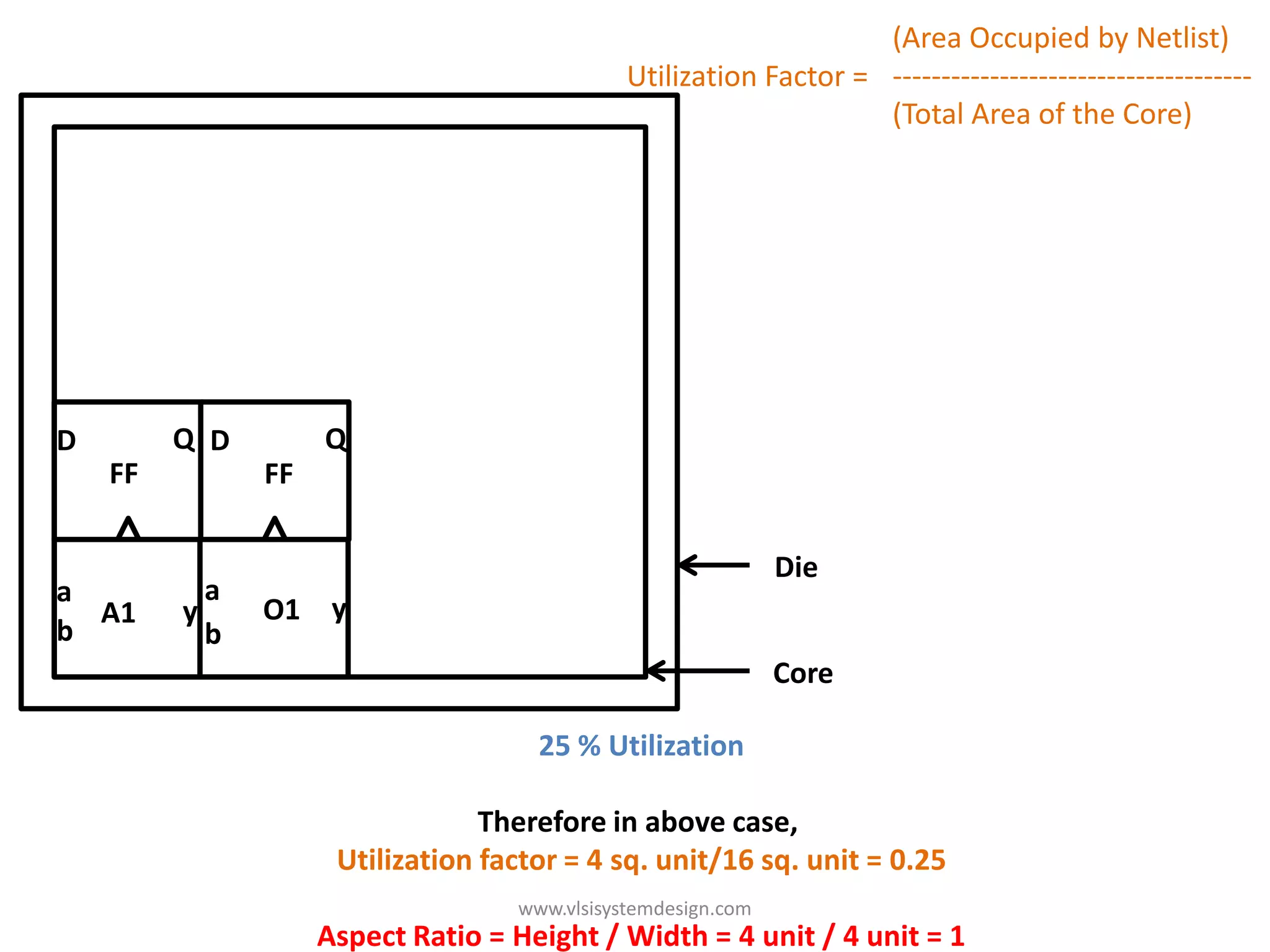
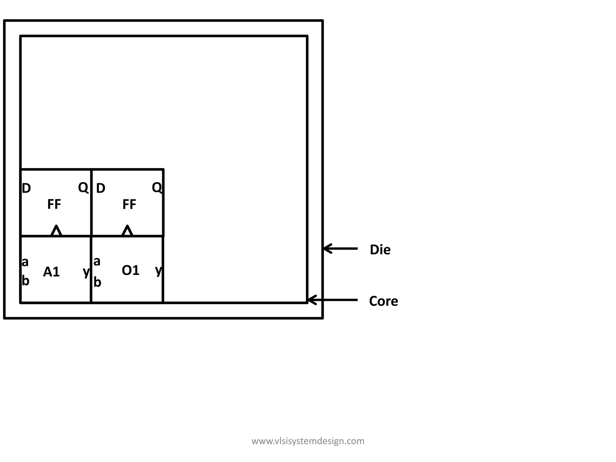
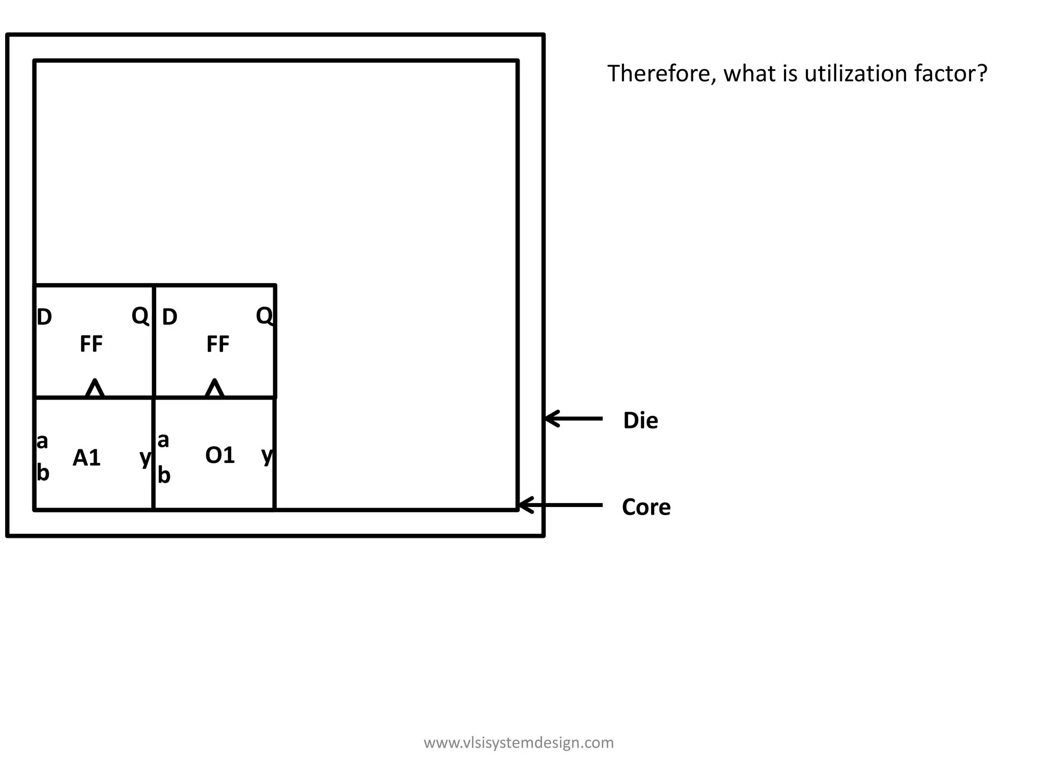
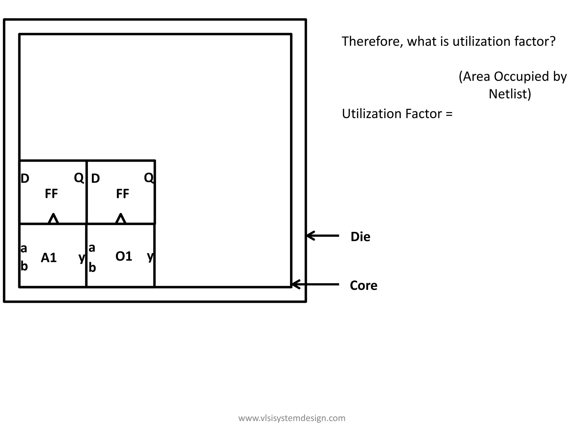
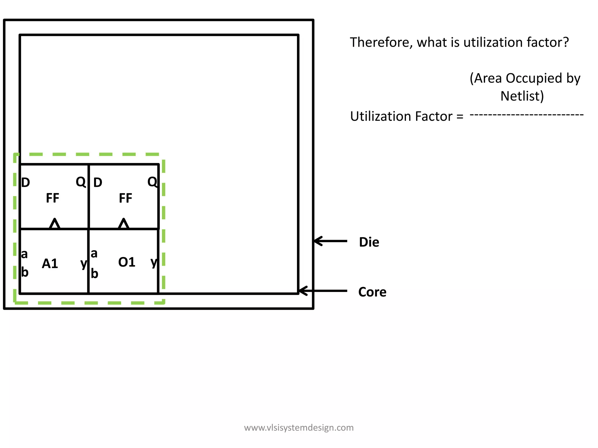
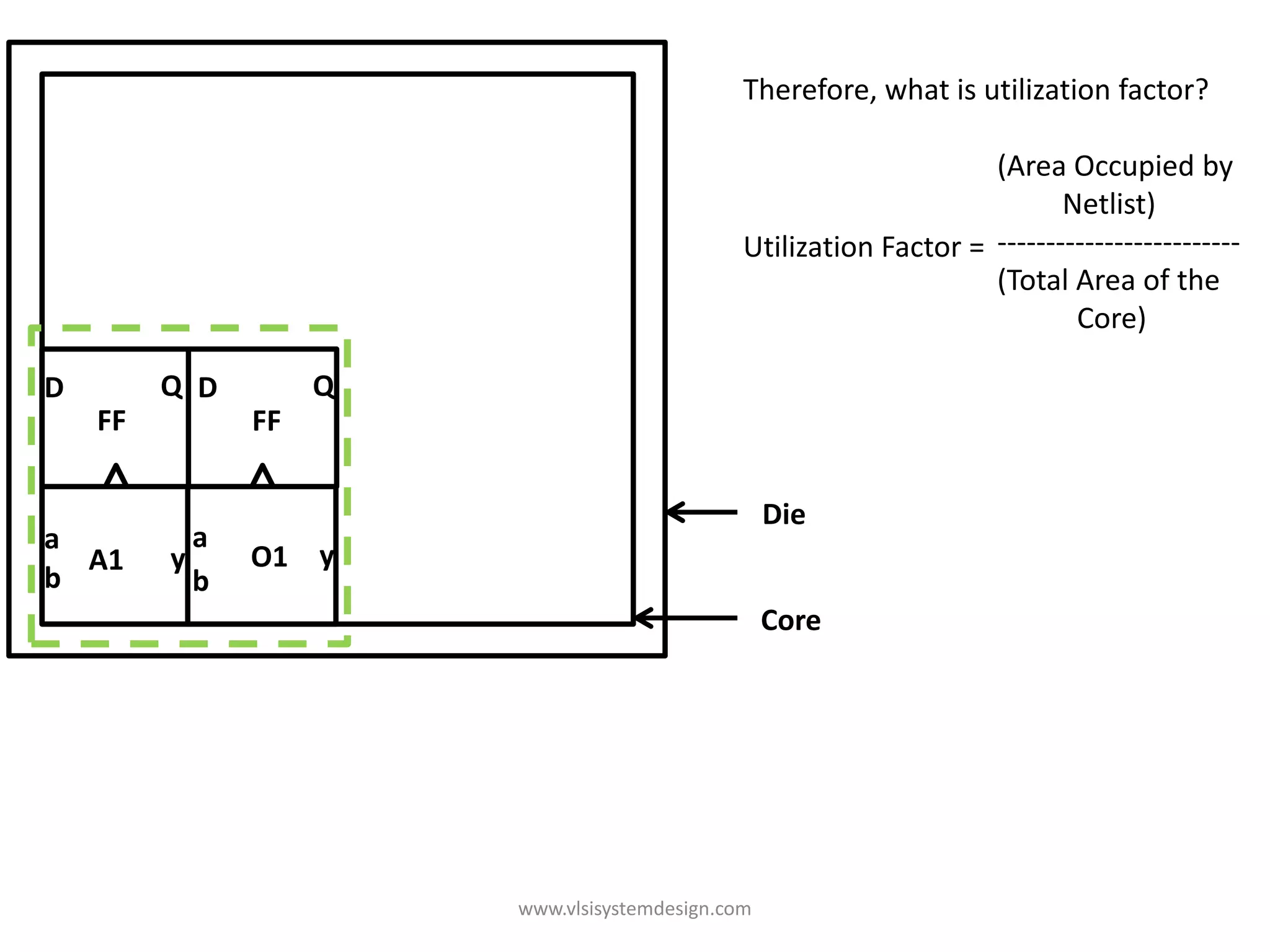
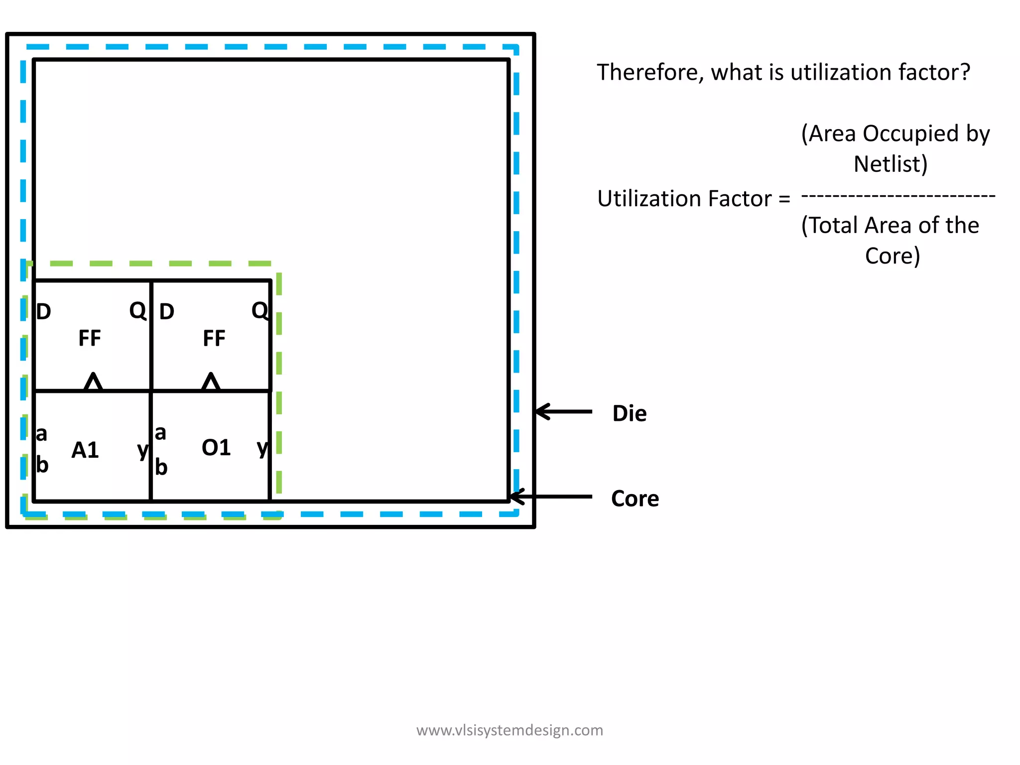
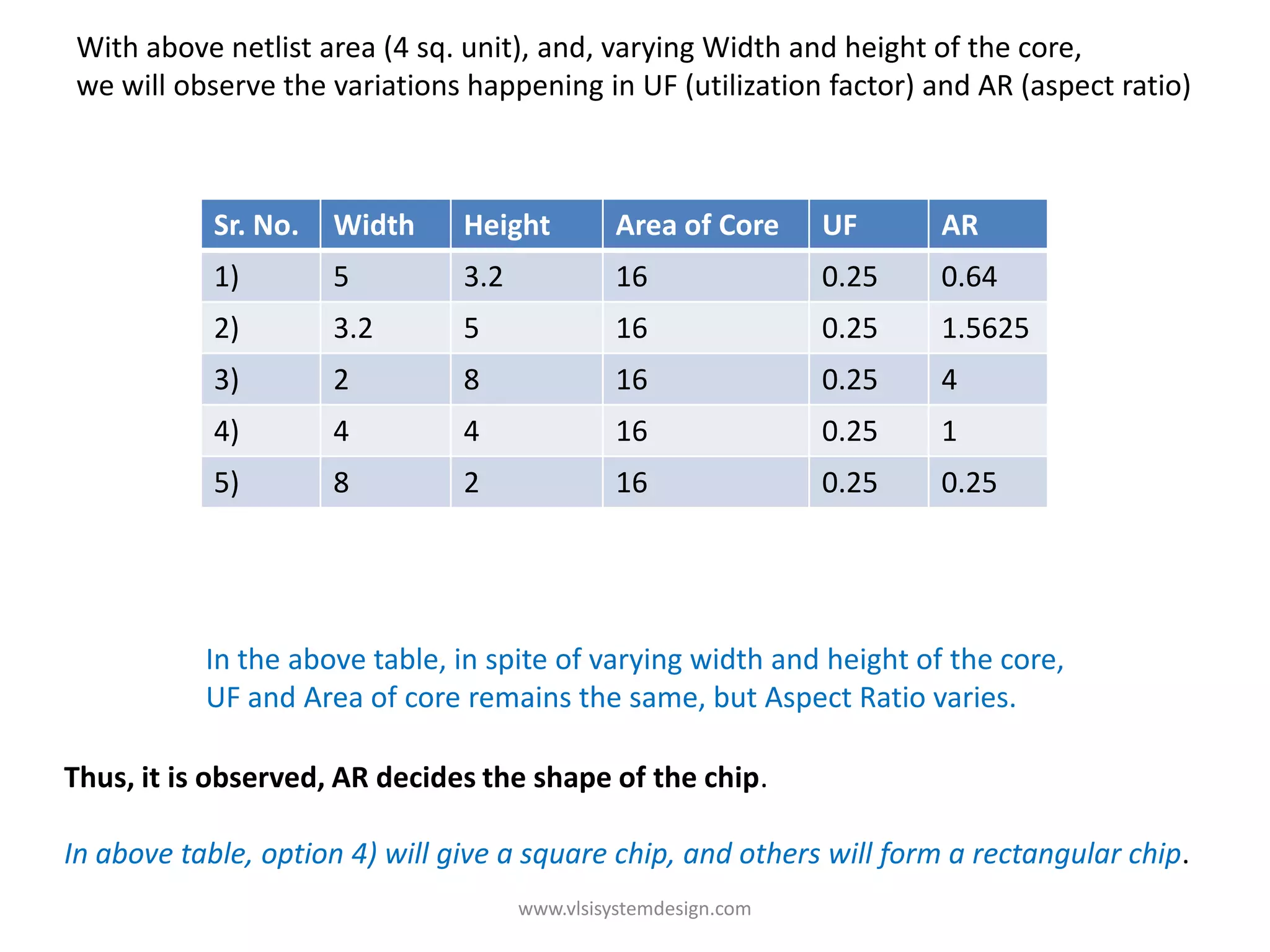
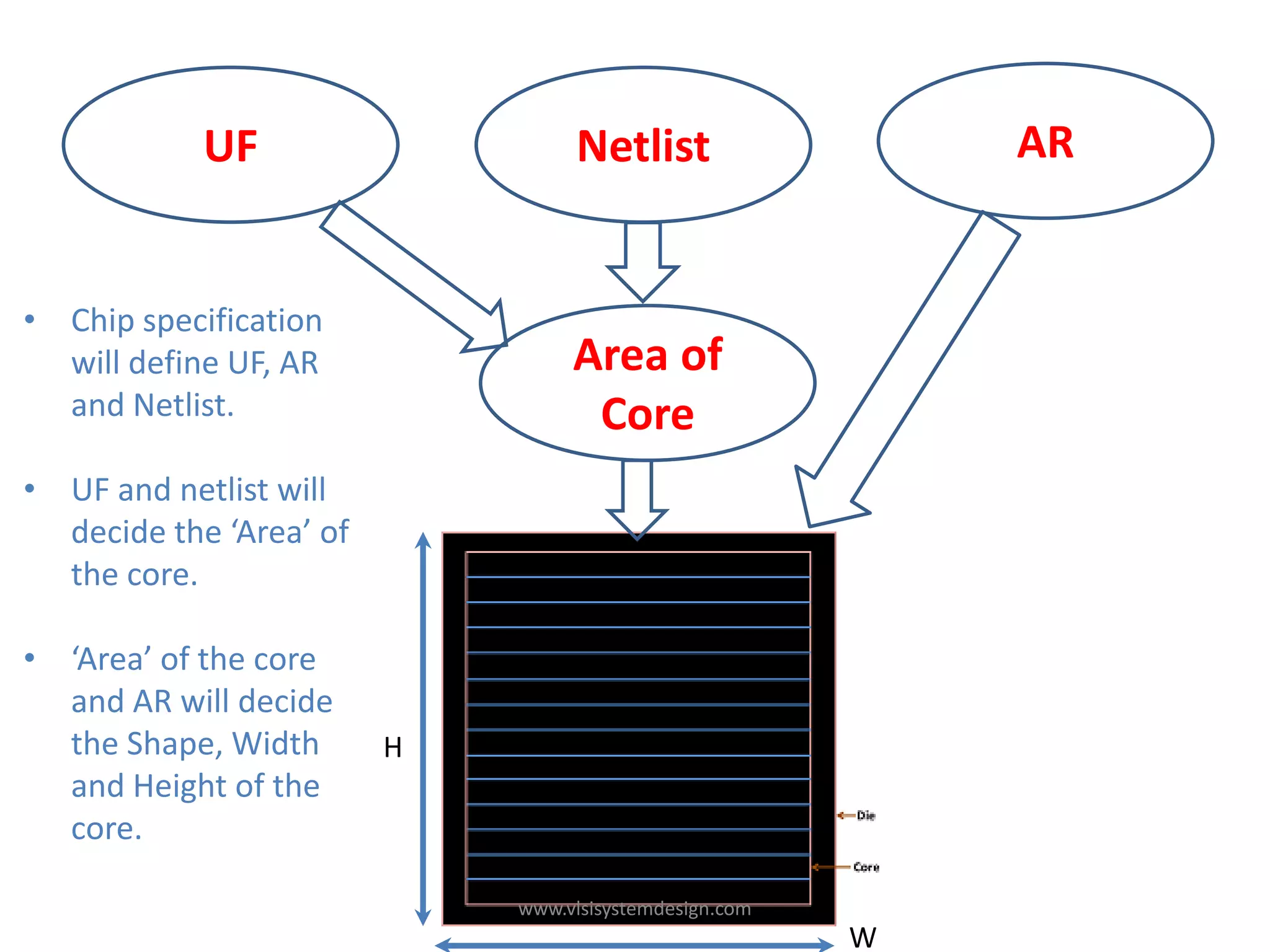
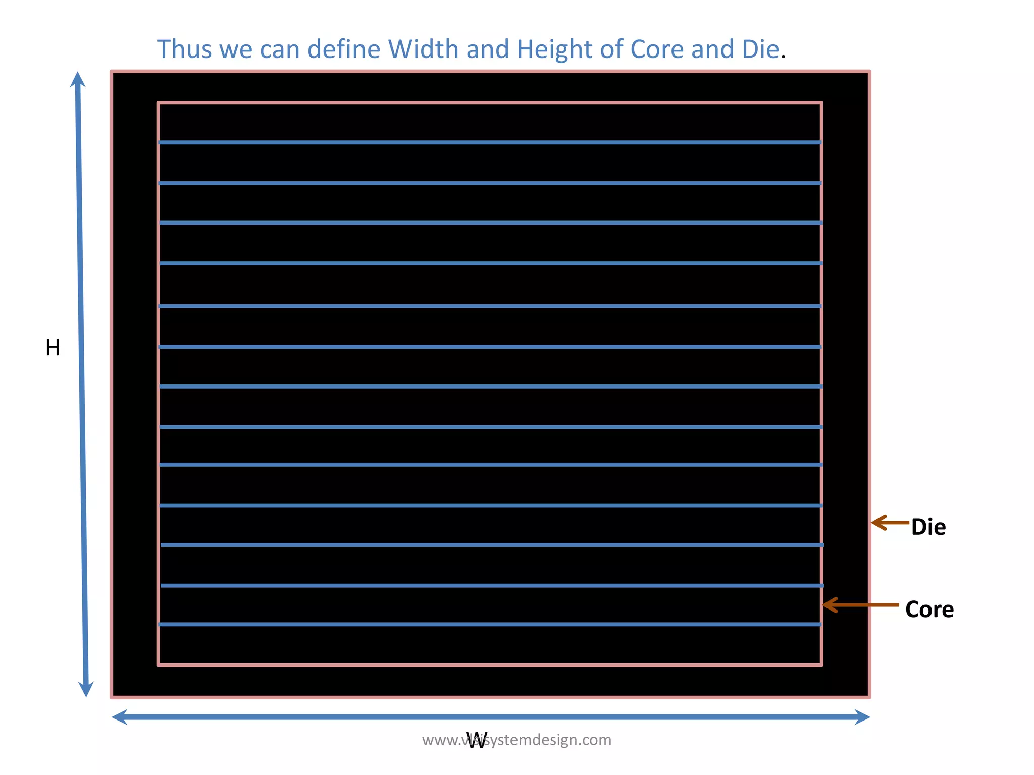
Memory                Processor


                    output
    Input


            Power


www.vlsisystemdesign.com
Intro slide                                               {Speed, Functionality (touch screen,
                                                          Internet, chatting, etc), Battery
                                                          Power, Size, etc …… “
                                                                         ………….
                                                                         ………….
              Specifications
                    To
                   RTL                                    module 8085 (clk, rst1, rst2, en, ….
                                                          )
                                                          ….
                                                          ….
                                                          …..
                                                          End module


                               www.vlsisystemdesign.com
{Speed, Functionality (touch screen,
                                            Internet, chatting, etc), Battery
                                            Power, Size, etc …… “
                                                           ………….
                                                           ………….
Specifications
      To
     RTL                                    module 8085 (clk, rst1, rst2, en, ….
                                            )
                                            ….
                                            ….
                                            …..
                                            End module


     RTL
     To
     GDS


                 www.vlsisystemdesign.com
{Speed, Functionality (touch screen,
                                            Internet, chatting, etc), Battery
                                            Power, Size, etc …… “
                                                           ………….
                                                           ………….
Specifications
      To
     RTL                                    module 8085 (clk, rst1, rst2, en, ….
                                            )
                                            ….
                                            ….
                                            …..
                                            End module


     RTL
     To
     GDS


     GDS
      To
  Fabrication


                 www.vlsisystemdesign.com
{Speed, Functionality (touch screen,
                                              Internet, chatting, etc), Battery
                                              Power, Size, etc …… “
                                                             ………….
                                                             ………….
  Specifications
        To
       RTL                                    module 8085 (clk, rst1, rst2, en, ….
                                              )
                                              ….
                                              ….
                                              …..
                                              End module


       RTL
       To
       GDS


       GDS
        To
    Fabrication


We will explore the Physical Aspects of Chip Design
                   www.vlsisystemdesign.com
We will explore the Physical Aspects of Chip Design


                www.vlsisystemdesign.com
We will explore the Physical Aspects of Chip Design

The first step to understand the physical aspects of a chip is


                     www.vlsisystemdesign.com
We will explore the Physical Aspects of Chip Design

The first step to understand the physical aspects of a chip is

               Area of Core and Die of Chip


                     www.vlsisystemdesign.com
We will explore the Physical Aspects of Chip Design

The first step to understand the physical aspects of a chip is

               Area of Core and Die of Chip


                                                                 Die

                                                                 Core


                     www.vlsisystemdesign.com
Let’s Begin with a netlist


       www.vlsisystemdesign.com
Let’s Begin with a netlist


                              a
                                A1 y
            D        Q        b                             D        Q
                                                   a
                FF                                   O1 y       FF
                                                   b


Clk


      FF = FlipFlops/Latches/Registers
      A1, O1 = Standard Cells (AND, OR, INVERTER)


                                 www.vlsisystemdesign.com
Let’s Begin with a netlist


                              a
                                A1 y
            D        Q        b                             D        Q
                                                   a
                FF                                   O1 y       FF
                                                   b


Clk


      FF = FlipFlops/Latches/Registers
      A1, O1 = Standard Cells (AND, OR, INVERTER)


Consider, a netlist with 2 flops and 2 gates, with above shown connections
Note : A "netlist" describes the connectivity of an electronic design.
                                 www.vlsisystemdesign.com
a
                                A1 y
            D        Q        b                             D        Q
                                                   a
                FF                                   O1 y       FF
                                                   b


Clk


      FF = FlipFlops/Latches/Registers
      A1, O1 = Standard Cells (AND, OR, INVERTER)


                                 www.vlsisystemdesign.com
Now, lets convert the highlighted symbols into physical dimension


                           a
                             A1 y
          D        Q       b                             D        Q
                                                a
              FF                                  O1 y       FF
                                                b


Clk


                              www.vlsisystemdesign.com
Now, lets convert the highlighted symbols into physical dimension


                           a
                             A1 y
          D        Q       b                             D        Q
                                                a
              FF                                  O1 y       FF
                                                b


Clk


                          a
                            A1      y
          D        Q      b                              D        Q
                                             a a
              FF                                 O1 yy       FF
                                             b b


Clk

                              www.vlsisystemdesign.com
Now, lets convert the highlighted symbols into physical dimension


                          a
                            A1      y
          D        Q      b                              D        Q
                                             a a
              FF                                 O1 yy       FF
                                             b b


Clk


                              www.vlsisystemdesign.com
Let’s group combinational gates together into standard cells


                       a
                         A1      y
      D        Q       b                              D        Q
                                          a a
          FF                                  O1 yy       FF
                                          b b


Clk


                           www.vlsisystemdesign.com
Let’s group combinational gates together into standard cells


                        a
                          A1      y
        D        Q      b                              D        Q
                                           a a
            FF                                 O1 yy       FF
                                           b b


Clk


a Std.
        y
b Cells


                            www.vlsisystemdesign.com
Let the length and breadth of std cell be 1 unit


                           a
                             A1      y
           D        Q      b                              D        Q
                                              a a
               FF                                 O1 yy       FF
                                              b b


Clk


a Std.
        y
b Cells


  1 unit


                               www.vlsisystemdesign.com
Let the length and breadth of std cell be 1 unit


                           a
                             A1      y
           D        Q      b                              D        Q
                                              a a
               FF                                 O1 yy       FF
                                              b b


Clk


a Std.         1 unit
        y
b Cells


  1 unit


                               www.vlsisystemdesign.com
Thus, the area of 1 std cell = 1 sq.unit


                             a
                               A1         y
           D         Q       b                                 D        Q
                                                   a a
               FF                                      O1 yy       FF
                                                   b b


Clk


                             Area
a Std.         1 unit
        y
b Cells


  1 unit


                                    www.vlsisystemdesign.com
Thus, the area of 1 std cell = 1 sq.unit


                             a
                               A1         y
           D         Q       b                                  D        Q
                                                   a a
               FF                                      O1 yy        FF
                                                   b b


Clk


                             Area
a Std.         1 unit                              1 sq. unit
        y
b Cells


  1 unit


                                    www.vlsisystemdesign.com
Similarly, let’s group flops together, assign dimensions, and calculate area


                             a
                               A1         y
             D        Q      b                                  D        Q
                                                   a a
                 FF                                    O1 yy        FF
                                                   b b


Clk


                             Area
a Std.           1 unit                            1 sq. unit
        y
b Cells


    1 unit


D            Q
      FF
                                    www.vlsisystemdesign.com
Similarly, let’s group flops together, assign dimensions, and calculate area


                             a
                               A1         y
             D        Q      b                                  D        Q
                                                   a a
                 FF                                    O1 yy        FF
                                                   b b


Clk


                             Area
a Std.           1 unit                            1 sq. unit
        y
b Cells


    1 unit

                             Area
D            Q
                 1 unit                            1 sq. unit
      FF
                                    www.vlsisystemdesign.com
Let us understand
                 The area occupied by the below netlist on a Silicon Wafer


                               a
                                 A1         y
             D         Q       b                                  D        Q
                                                     a a
                  FF                                     O1 yy        FF
                                                     b b


Clk


                               Area
a Std.             1 unit                            1 sq. unit
        y
b Cells


    1 unit

                               Area
D            Q
                   1 unit                            1 sq. unit
      FF
                                      www.vlsisystemdesign.com
D            Q
                 FF


                               a
                                 A1         y
                               b                                  D        Q
                                                     a a
                                                         O1 yy        FF
                                                     b b


                               Area
a Std.                1 unit                         1 sq. unit
        y
b Cells


    1 unit

                               Area
D            Q
                      1 unit                         1 sq. unit
     FF
                                      www.vlsisystemdesign.com
D            Q D          Q
                 FF            FF


                                    a
                                      A1         y
                                    b
                                                          a a
                                                              O1 yy
                                                          b b


                                    Area
a Std.                1 unit                              1 sq. unit
        y
b Cells


    1 unit

                                    Area
D            Q
                      1 unit                              1 sq. unit
     FF
                                           www.vlsisystemdesign.com
D            Q D          Q
                 FF            FF


          a
            A1          y
          b                                               a a
                                                              O1 yy
                                                          b b


                                    Area
a Std.                1 unit                              1 sq. unit
        y
b Cells


    1 unit

                                    Area
D            Q
                      1 unit                              1 sq. unit
     FF
                                           www.vlsisystemdesign.com
D            Q D          Q
                 FF            FF


          a                 a a
            A1          y       O1 yy
          b                 b b


Let’s group flops and std cells together, assign dimensions, and calculate area


                                    Area
a Std.                1 unit                              1 sq. unit
        y
b Cells


    1 unit

                                    Area
D            Q
                      1 unit                              1 sq. unit
     FF
                                           www.vlsisystemdesign.com
D            Q D              Q
                 FF              FF              1 unit
                                                                   Area
                                                                           4 sq. unit
          a                 a a
            A1          y       O1 yy            1 unit
          b                 b b


              1 unit           1 unit

Let’s group flops and std cells together, assign dimensions, and calculate area


                                        Area
a Std.                1 unit                                  1 sq. unit
        y
b Cells


    1 unit

                                        Area
D            Q
                      1 unit                                  1 sq. unit
     FF
                                               www.vlsisystemdesign.com
D        Q D         Q
    FF          FF             Now, lets understand,
                               What is ‘core’ and ‘die’ Section of a chip ?
                               and
a            a a               How to arrive on its dimensions?
  A1     y       O1 yy
b            b b


                         www.vlsisystemdesign.com
D        Q D         Q
    FF          FF
                                           What is ‘core’ and ‘die’ Section of a chip ?

a            a a
  A1     y       O1 yy
b            b b


                                                                  Core


                         A 'core' is the section of the chip where
                         the fundamental logic of the design is
                         placed.
                                     www.vlsisystemdesign.com
D        Q D         Q
    FF          FF
                                            What is ‘core’ and ‘die’ Section of a chip ?

a            a a
  A1     y       O1 yy
b            b b


                                                                     Die


                                                                     Core


                         A ‘die’, which consists of core, is small
                         semiconductor material specimen on
                         which the fundamental circuit is
                         fabricated.
                                      www.vlsisystemdesign.com
How to arrive on its dimensions?


           D          Q D             Q
                FF              FF

                                            Die
           a             a a
             A1        y     O1 yy
           b             b b
                                            Core


Place all logical cells inside the ‘core’


               www.vlsisystemdesign.com
As shown below, the logical cells occupies
          the complete area of the core, the core is
          said to be 100% utilized.


D          Q D             Q
     FF              FF

                                Die
a             a a
  A1        y     O1 yy
b             b b
                                Core


     100 % Utilization


    www.vlsisystemdesign.com
(Area Occupied by Netlist)
                      Utilization Factor = -------------------------------------
                                           (Total Area of the Core)


            D         Q D          Q
                FF            FF

                                                  Die
            a           a a
              A1      y     O1 yy
            b           b b
                                                 Core


                100 % Utilization

             Therefore in above case,
   Utilization factor = 4 sq. unit/4 sq. unit = 1

               www.vlsisystemdesign.com
Aspect Ratio = Height / Width = 2 unit / 2 unit = 1
Now, let us understand
                 The impact on “Utilization factor” and
                 “Aspect Ratio”, by varying ‘core width’


D        Q D          Q
    FF          FF

                                                    Die
a          a a
  A1     y     O1 yy
b          b b
                                                    Core


           www.vlsisystemdesign.com
As shown below, the logical cells occupies
                  ‘half’ the area of the core, the core is said
                  to be 50% utilized.


D        Q D          Q
    FF           FF

                                                       Die
a          a a
  A1     y     O1 yy
b          b b
                                                       Core


               50 % Utilization


           www.vlsisystemdesign.com
(Area Occupied by Netlist)
                       Utilization Factor = -------------------------------------
                                            (Total Area of the Core)


    D        Q D          Q
        FF           FF

                                                                   Die
    a           a a
      A1      y     O1 yy
    b           b b
                                                                   Core


                   50 % Utilization

             Therefore in above case,
   Utilization factor = 4 sq. unit/8 sq. unit = 0.5

                www.vlsisystemdesign.com
Aspect Ratio = Height / Width = 2 unit / 4 unit = 0.5
Now, let us understand
                                                The impact on “Utilization factor” and
                                                “Aspect Ratio”, by varying ‘core width’
                                                and ‘core height’


D        Q D         Q
    FF          FF

                                                        Die
a            a a
  A1     y       O1 yy
b            b b
                                                        Core


                         Core and dei relation


                             www.vlsisystemdesign.com
As shown below, the logical cells
                                             occupies ‘one-fourth’ the area of the
                                             core, the core is said to be 25%
                                             utilized.


D        Q D         Q
    FF          FF

                                                    Die
a            a a
  A1     y       O1 yy
b            b b
                                                    Core

                           25 % Utilization


                         www.vlsisystemdesign.com
(Area Occupied by Netlist)
                                               Utilization Factor = -------------------------------------
                                                                    (Total Area of the Core)


D        Q D         Q
    FF          FF

                                                               Die
a            a a
  A1     y       O1 yy
b            b b
                                                               Core

                                      25 % Utilization

                                  Therefore in above case,
                      Utilization factor = 4 sq. unit/16 sq. unit = 0.25
                                    www.vlsisystemdesign.com
                     Aspect Ratio = Height / Width = 4 unit / 4 unit = 1
D        Q D        Q
    FF         FF

                                                   Die
a          a a
  A1     y     O1 yy
b          b b
                                                   Core


                        www.vlsisystemdesign.com
Therefore, what is utilization factor?


D        Q D        Q
    FF         FF

                                                   Die
a          a a
  A1     y     O1 yy
b          b b
                                                   Core


                        www.vlsisystemdesign.com
Therefore, what is utilization factor?

                                                                      (Area Occupied by
                                                                           Netlist)
                                               Utilization Factor =


D        Q D        Q
    FF         FF

                                                   Die
a          a a
  A1     y     O1 yy
b          b b
                                                   Core


                        www.vlsisystemdesign.com
Therefore, what is utilization factor?

                                                                    (Area Occupied by
                                                                           Netlist)
                                               Utilization Factor = -------------------------
                                                                    (Total Area of the
                                                                            Core)

D        Q D        Q
    FF         FF

                                                   Die
a          a a
  A1     y     O1 yy
b          b b
                                                   Core


                        www.vlsisystemdesign.com
With above netlist area (4 sq. unit), and, varying Width and height of the core,
we will observe the variations happening in UF (utilization factor) and AR (aspect ratio)


            Sr. No.   Width     Height          Area of Core     UF     AR
            1)        5         3.2             16               0.25   0.64
            2)        3.2       5               16               0.25   1.5625
            3)        2         8               16               0.25   4
            4)        4         4               16               0.25   1
            5)        8         2               16               0.25   0.25


           In the above table, in spite of varying width and height of the core,
           UF and Area of core remains the same, but Aspect Ratio varies.

Thus, it is observed, AR decides the shape of the chip.

In above table, option 4) will give a square chip, and others will form a rectangular chip.
                                      www.vlsisystemdesign.com
UF                    Netlist                   AR


• Chip specification
  will define UF, AR              Area of
  and Netlist.                     Core
• UF and netlist will
  decide the ‘Area’ of
  the core.

• ‘Area’ of the core
  and AR will decide
  the Shape, Width       H
  and Height of the
  core.

                             www.vlsisystemdesign.com
                                                        W
Thus we can define Width and Height of Core and Die.


H


                                                           Die


                                                           Core


                              W
                         www.vlsisystemdesign.com

Define Width and Height of Core and Die (http://www.vlsisystemdesign.com/PD-Flow.php)

  • 1.
    Memory Processor output Input Power www.vlsisystemdesign.com
  • 2.
    Intro slide {Speed, Functionality (touch screen, Internet, chatting, etc), Battery Power, Size, etc …… “ …………. …………. Specifications To RTL module 8085 (clk, rst1, rst2, en, …. ) …. …. ….. End module www.vlsisystemdesign.com
  • 3.
    {Speed, Functionality (touchscreen, Internet, chatting, etc), Battery Power, Size, etc …… “ …………. …………. Specifications To RTL module 8085 (clk, rst1, rst2, en, …. ) …. …. ….. End module RTL To GDS www.vlsisystemdesign.com
  • 4.
    {Speed, Functionality (touchscreen, Internet, chatting, etc), Battery Power, Size, etc …… “ …………. …………. Specifications To RTL module 8085 (clk, rst1, rst2, en, …. ) …. …. ….. End module RTL To GDS GDS To Fabrication www.vlsisystemdesign.com
  • 5.
    {Speed, Functionality (touchscreen, Internet, chatting, etc), Battery Power, Size, etc …… “ …………. …………. Specifications To RTL module 8085 (clk, rst1, rst2, en, …. ) …. …. ….. End module RTL To GDS GDS To Fabrication We will explore the Physical Aspects of Chip Design www.vlsisystemdesign.com
  • 6.
    We will explorethe Physical Aspects of Chip Design www.vlsisystemdesign.com
  • 7.
    We will explorethe Physical Aspects of Chip Design The first step to understand the physical aspects of a chip is www.vlsisystemdesign.com
  • 8.
    We will explorethe Physical Aspects of Chip Design The first step to understand the physical aspects of a chip is Area of Core and Die of Chip www.vlsisystemdesign.com
  • 9.
    We will explorethe Physical Aspects of Chip Design The first step to understand the physical aspects of a chip is Area of Core and Die of Chip Die Core www.vlsisystemdesign.com
  • 10.
    Let’s Begin witha netlist www.vlsisystemdesign.com
  • 11.
    Let’s Begin witha netlist a A1 y D Q b D Q a FF O1 y FF b Clk FF = FlipFlops/Latches/Registers A1, O1 = Standard Cells (AND, OR, INVERTER) www.vlsisystemdesign.com
  • 12.
    Let’s Begin witha netlist a A1 y D Q b D Q a FF O1 y FF b Clk FF = FlipFlops/Latches/Registers A1, O1 = Standard Cells (AND, OR, INVERTER) Consider, a netlist with 2 flops and 2 gates, with above shown connections Note : A "netlist" describes the connectivity of an electronic design. www.vlsisystemdesign.com
  • 13.
    a A1 y D Q b D Q a FF O1 y FF b Clk FF = FlipFlops/Latches/Registers A1, O1 = Standard Cells (AND, OR, INVERTER) www.vlsisystemdesign.com
  • 14.
    Now, lets convertthe highlighted symbols into physical dimension a A1 y D Q b D Q a FF O1 y FF b Clk www.vlsisystemdesign.com
  • 15.
    Now, lets convertthe highlighted symbols into physical dimension a A1 y D Q b D Q a FF O1 y FF b Clk a A1 y D Q b D Q a a FF O1 yy FF b b Clk www.vlsisystemdesign.com
  • 16.
    Now, lets convertthe highlighted symbols into physical dimension a A1 y D Q b D Q a a FF O1 yy FF b b Clk www.vlsisystemdesign.com
  • 17.
    Let’s group combinationalgates together into standard cells a A1 y D Q b D Q a a FF O1 yy FF b b Clk www.vlsisystemdesign.com
  • 18.
    Let’s group combinationalgates together into standard cells a A1 y D Q b D Q a a FF O1 yy FF b b Clk a Std. y b Cells www.vlsisystemdesign.com
  • 19.
    Let the lengthand breadth of std cell be 1 unit a A1 y D Q b D Q a a FF O1 yy FF b b Clk a Std. y b Cells 1 unit www.vlsisystemdesign.com
  • 20.
    Let the lengthand breadth of std cell be 1 unit a A1 y D Q b D Q a a FF O1 yy FF b b Clk a Std. 1 unit y b Cells 1 unit www.vlsisystemdesign.com
  • 21.
    Thus, the areaof 1 std cell = 1 sq.unit a A1 y D Q b D Q a a FF O1 yy FF b b Clk Area a Std. 1 unit y b Cells 1 unit www.vlsisystemdesign.com
  • 22.
    Thus, the areaof 1 std cell = 1 sq.unit a A1 y D Q b D Q a a FF O1 yy FF b b Clk Area a Std. 1 unit 1 sq. unit y b Cells 1 unit www.vlsisystemdesign.com
  • 23.
    Similarly, let’s groupflops together, assign dimensions, and calculate area a A1 y D Q b D Q a a FF O1 yy FF b b Clk Area a Std. 1 unit 1 sq. unit y b Cells 1 unit D Q FF www.vlsisystemdesign.com
  • 24.
    Similarly, let’s groupflops together, assign dimensions, and calculate area a A1 y D Q b D Q a a FF O1 yy FF b b Clk Area a Std. 1 unit 1 sq. unit y b Cells 1 unit Area D Q 1 unit 1 sq. unit FF www.vlsisystemdesign.com
  • 25.
    Let us understand The area occupied by the below netlist on a Silicon Wafer a A1 y D Q b D Q a a FF O1 yy FF b b Clk Area a Std. 1 unit 1 sq. unit y b Cells 1 unit Area D Q 1 unit 1 sq. unit FF www.vlsisystemdesign.com
  • 26.
    D Q FF a A1 y b D Q a a O1 yy FF b b Area a Std. 1 unit 1 sq. unit y b Cells 1 unit Area D Q 1 unit 1 sq. unit FF www.vlsisystemdesign.com
  • 27.
    D Q D Q FF FF a A1 y b a a O1 yy b b Area a Std. 1 unit 1 sq. unit y b Cells 1 unit Area D Q 1 unit 1 sq. unit FF www.vlsisystemdesign.com
  • 28.
    D Q D Q FF FF a A1 y b a a O1 yy b b Area a Std. 1 unit 1 sq. unit y b Cells 1 unit Area D Q 1 unit 1 sq. unit FF www.vlsisystemdesign.com
  • 29.
    D Q D Q FF FF a a a A1 y O1 yy b b b Let’s group flops and std cells together, assign dimensions, and calculate area Area a Std. 1 unit 1 sq. unit y b Cells 1 unit Area D Q 1 unit 1 sq. unit FF www.vlsisystemdesign.com
  • 30.
    D Q D Q FF FF 1 unit Area 4 sq. unit a a a A1 y O1 yy 1 unit b b b 1 unit 1 unit Let’s group flops and std cells together, assign dimensions, and calculate area Area a Std. 1 unit 1 sq. unit y b Cells 1 unit Area D Q 1 unit 1 sq. unit FF www.vlsisystemdesign.com
  • 31.
    D Q D Q FF FF Now, lets understand, What is ‘core’ and ‘die’ Section of a chip ? and a a a How to arrive on its dimensions? A1 y O1 yy b b b www.vlsisystemdesign.com
  • 32.
    D Q D Q FF FF What is ‘core’ and ‘die’ Section of a chip ? a a a A1 y O1 yy b b b Core A 'core' is the section of the chip where the fundamental logic of the design is placed. www.vlsisystemdesign.com
  • 33.
    D Q D Q FF FF What is ‘core’ and ‘die’ Section of a chip ? a a a A1 y O1 yy b b b Die Core A ‘die’, which consists of core, is small semiconductor material specimen on which the fundamental circuit is fabricated. www.vlsisystemdesign.com
  • 34.
    How to arriveon its dimensions? D Q D Q FF FF Die a a a A1 y O1 yy b b b Core Place all logical cells inside the ‘core’ www.vlsisystemdesign.com
  • 35.
    As shown below,the logical cells occupies the complete area of the core, the core is said to be 100% utilized. D Q D Q FF FF Die a a a A1 y O1 yy b b b Core 100 % Utilization www.vlsisystemdesign.com
  • 36.
    (Area Occupied byNetlist) Utilization Factor = ------------------------------------- (Total Area of the Core) D Q D Q FF FF Die a a a A1 y O1 yy b b b Core 100 % Utilization Therefore in above case, Utilization factor = 4 sq. unit/4 sq. unit = 1 www.vlsisystemdesign.com Aspect Ratio = Height / Width = 2 unit / 2 unit = 1
  • 37.
    Now, let usunderstand The impact on “Utilization factor” and “Aspect Ratio”, by varying ‘core width’ D Q D Q FF FF Die a a a A1 y O1 yy b b b Core www.vlsisystemdesign.com
  • 38.
    As shown below,the logical cells occupies ‘half’ the area of the core, the core is said to be 50% utilized. D Q D Q FF FF Die a a a A1 y O1 yy b b b Core 50 % Utilization www.vlsisystemdesign.com
  • 39.
    (Area Occupied byNetlist) Utilization Factor = ------------------------------------- (Total Area of the Core) D Q D Q FF FF Die a a a A1 y O1 yy b b b Core 50 % Utilization Therefore in above case, Utilization factor = 4 sq. unit/8 sq. unit = 0.5 www.vlsisystemdesign.com Aspect Ratio = Height / Width = 2 unit / 4 unit = 0.5
  • 40.
    Now, let usunderstand The impact on “Utilization factor” and “Aspect Ratio”, by varying ‘core width’ and ‘core height’ D Q D Q FF FF Die a a a A1 y O1 yy b b b Core Core and dei relation www.vlsisystemdesign.com
  • 41.
    As shown below,the logical cells occupies ‘one-fourth’ the area of the core, the core is said to be 25% utilized. D Q D Q FF FF Die a a a A1 y O1 yy b b b Core 25 % Utilization www.vlsisystemdesign.com
  • 42.
    (Area Occupied byNetlist) Utilization Factor = ------------------------------------- (Total Area of the Core) D Q D Q FF FF Die a a a A1 y O1 yy b b b Core 25 % Utilization Therefore in above case, Utilization factor = 4 sq. unit/16 sq. unit = 0.25 www.vlsisystemdesign.com Aspect Ratio = Height / Width = 4 unit / 4 unit = 1
  • 43.
    D Q D Q FF FF Die a a a A1 y O1 yy b b b Core www.vlsisystemdesign.com
  • 44.
    Therefore, what isutilization factor? D Q D Q FF FF Die a a a A1 y O1 yy b b b Core www.vlsisystemdesign.com
  • 45.
    Therefore, what isutilization factor? (Area Occupied by Netlist) Utilization Factor = D Q D Q FF FF Die a a a A1 y O1 yy b b b Core www.vlsisystemdesign.com
  • 46.
    Therefore, what isutilization factor? (Area Occupied by Netlist) Utilization Factor = ------------------------- D Q D Q FF FF Die a a a A1 y O1 yy b b b Core www.vlsisystemdesign.com
  • 47.
    Therefore, what isutilization factor? (Area Occupied by Netlist) Utilization Factor = ------------------------- (Total Area of the Core) D Q D Q FF FF Die a a a A1 y O1 yy b b b Core www.vlsisystemdesign.com
  • 48.
    Therefore, what isutilization factor? (Area Occupied by Netlist) Utilization Factor = ------------------------- (Total Area of the Core) D Q D Q FF FF Die a a a A1 y O1 yy b b b Core www.vlsisystemdesign.com
  • 49.
    With above netlistarea (4 sq. unit), and, varying Width and height of the core, we will observe the variations happening in UF (utilization factor) and AR (aspect ratio) Sr. No. Width Height Area of Core UF AR 1) 5 3.2 16 0.25 0.64 2) 3.2 5 16 0.25 1.5625 3) 2 8 16 0.25 4 4) 4 4 16 0.25 1 5) 8 2 16 0.25 0.25 In the above table, in spite of varying width and height of the core, UF and Area of core remains the same, but Aspect Ratio varies. Thus, it is observed, AR decides the shape of the chip. In above table, option 4) will give a square chip, and others will form a rectangular chip. www.vlsisystemdesign.com
  • 50.
    UF Netlist AR • Chip specification will define UF, AR Area of and Netlist. Core • UF and netlist will decide the ‘Area’ of the core. • ‘Area’ of the core and AR will decide the Shape, Width H and Height of the core. www.vlsisystemdesign.com W
  • 51.
    Thus we candefine Width and Height of Core and Die. H Die Core W www.vlsisystemdesign.com