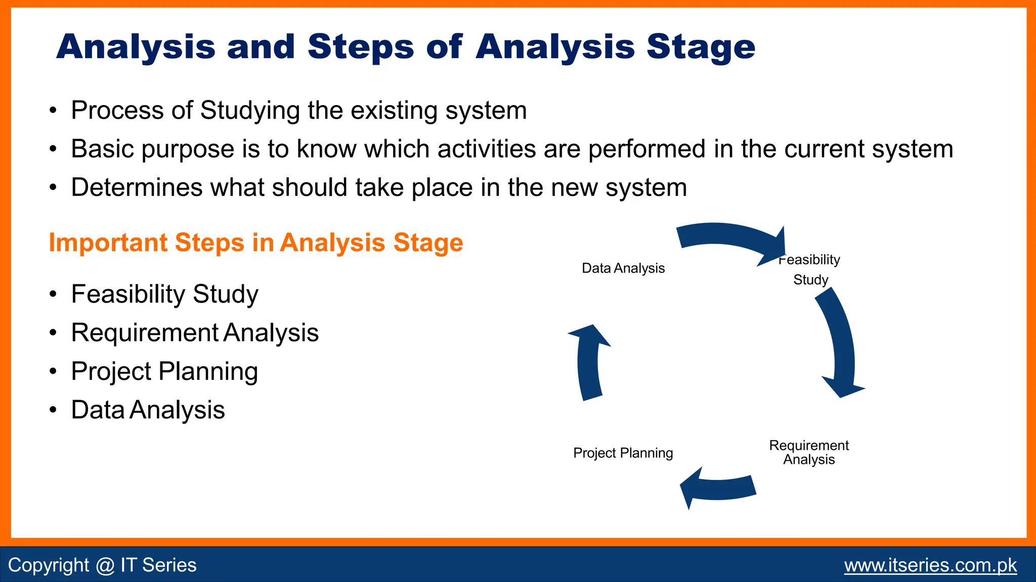
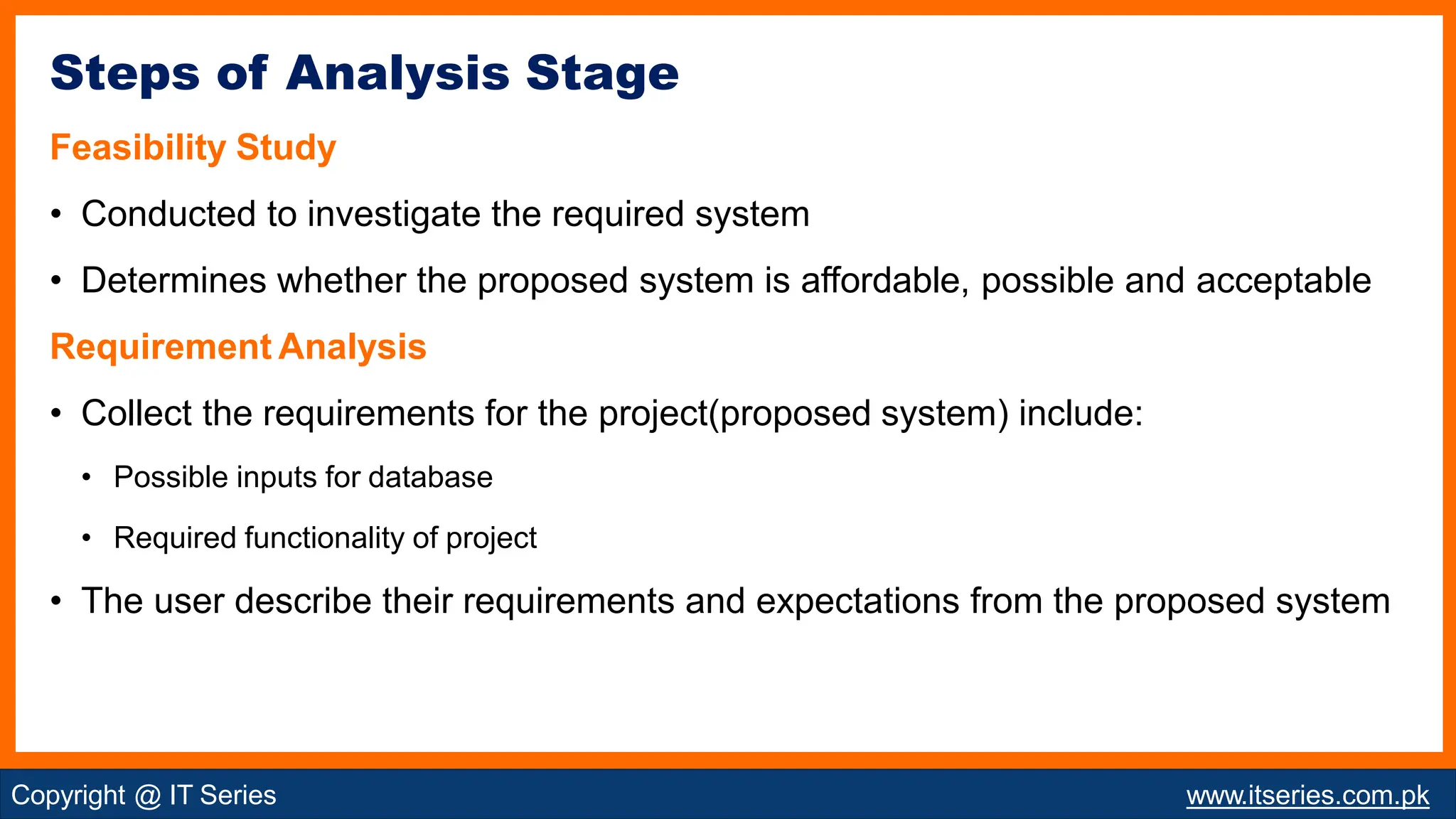
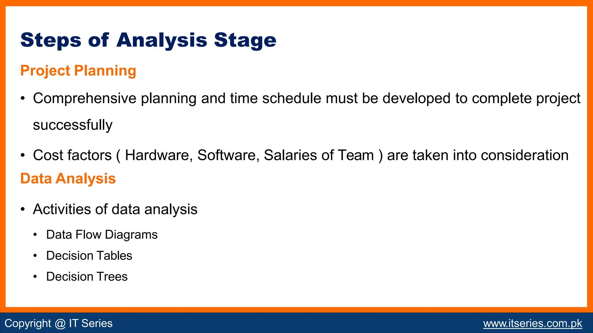
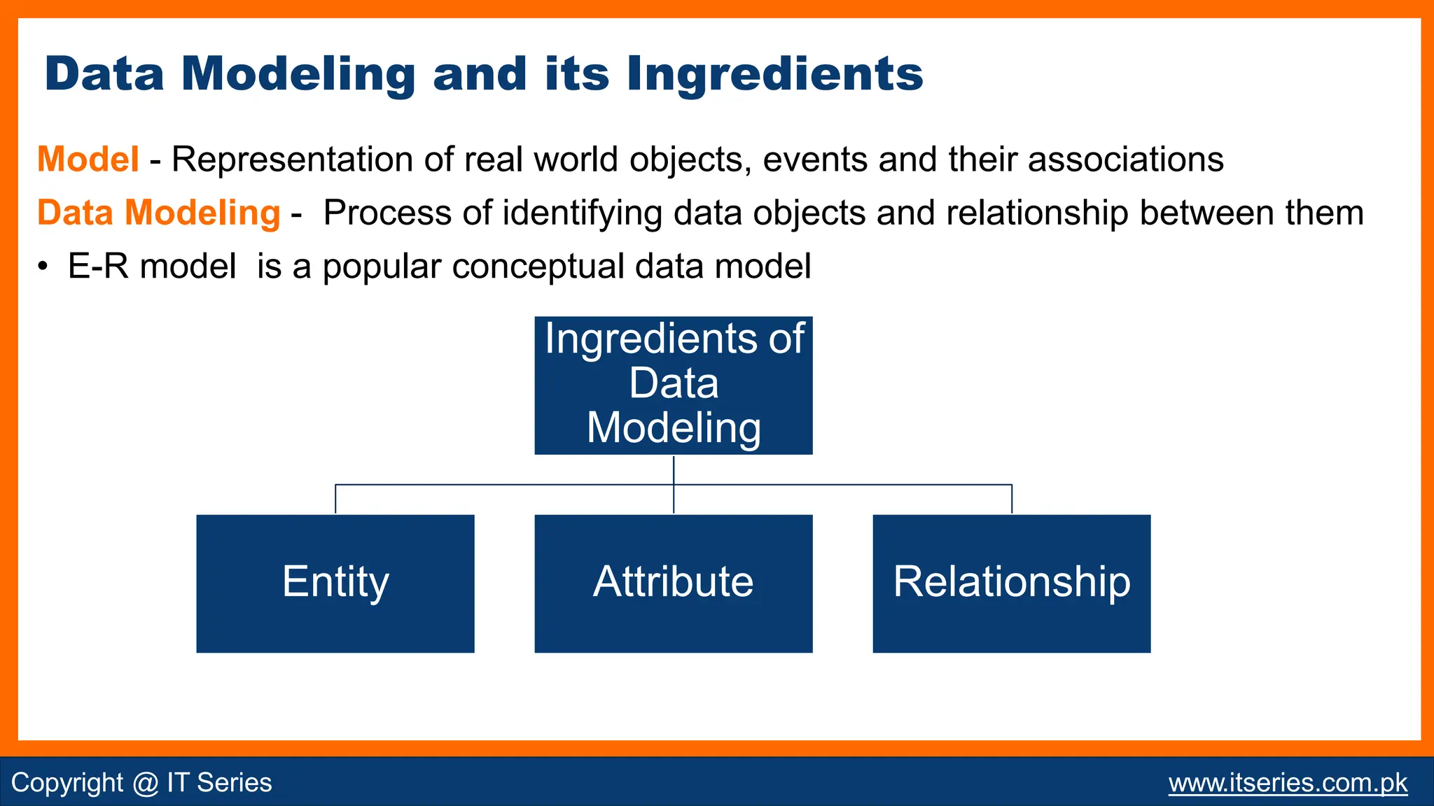
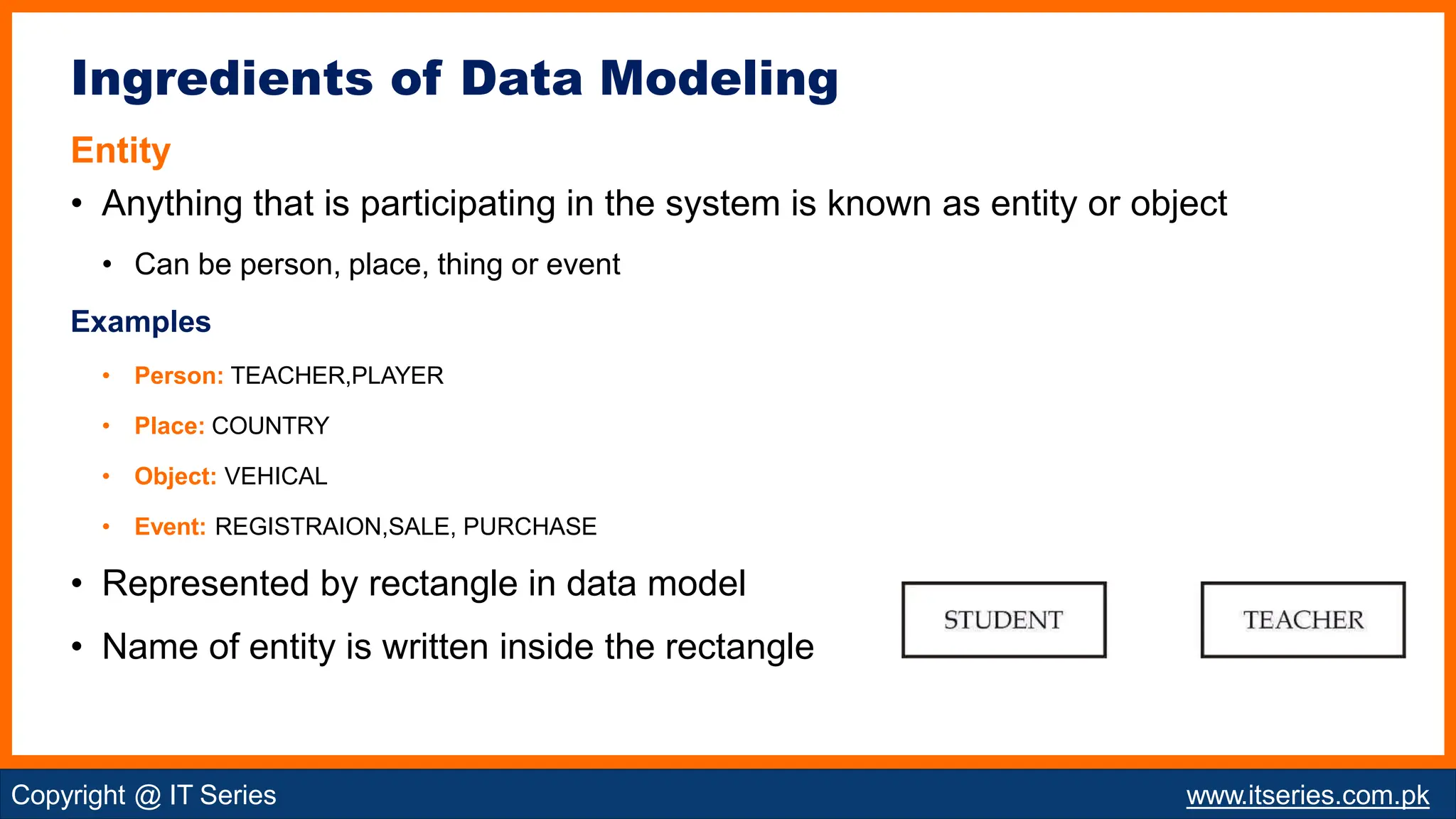
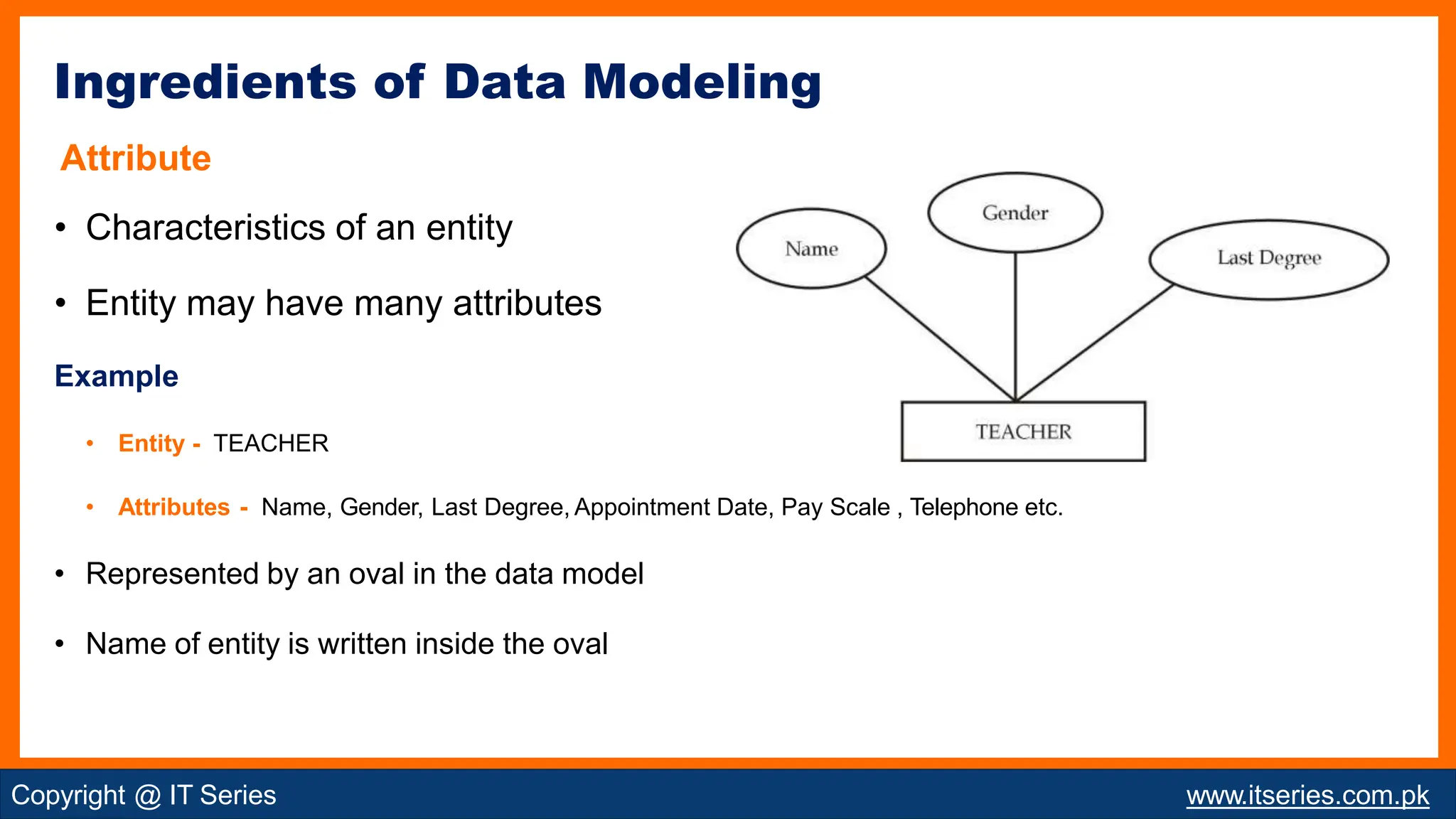
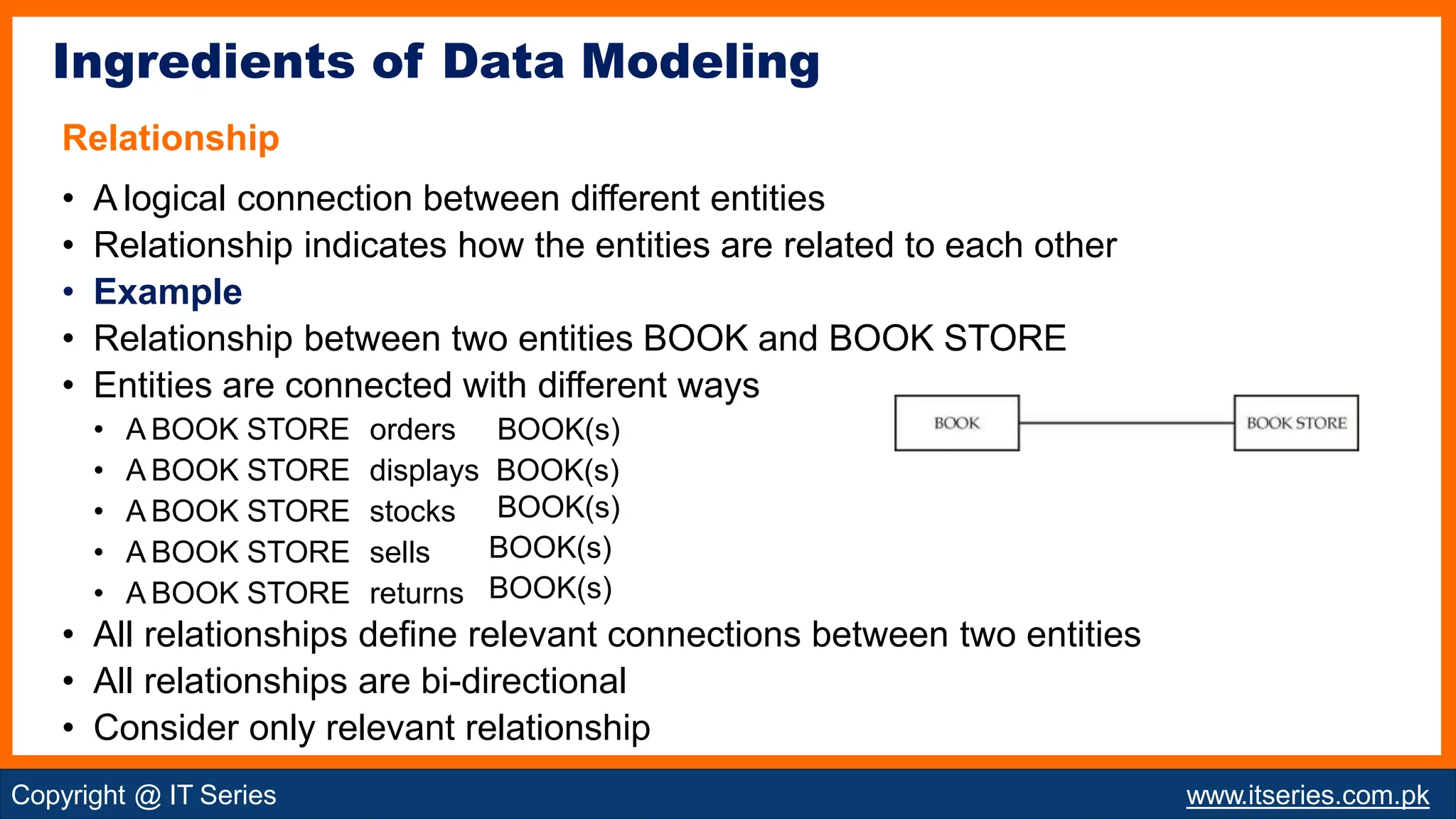
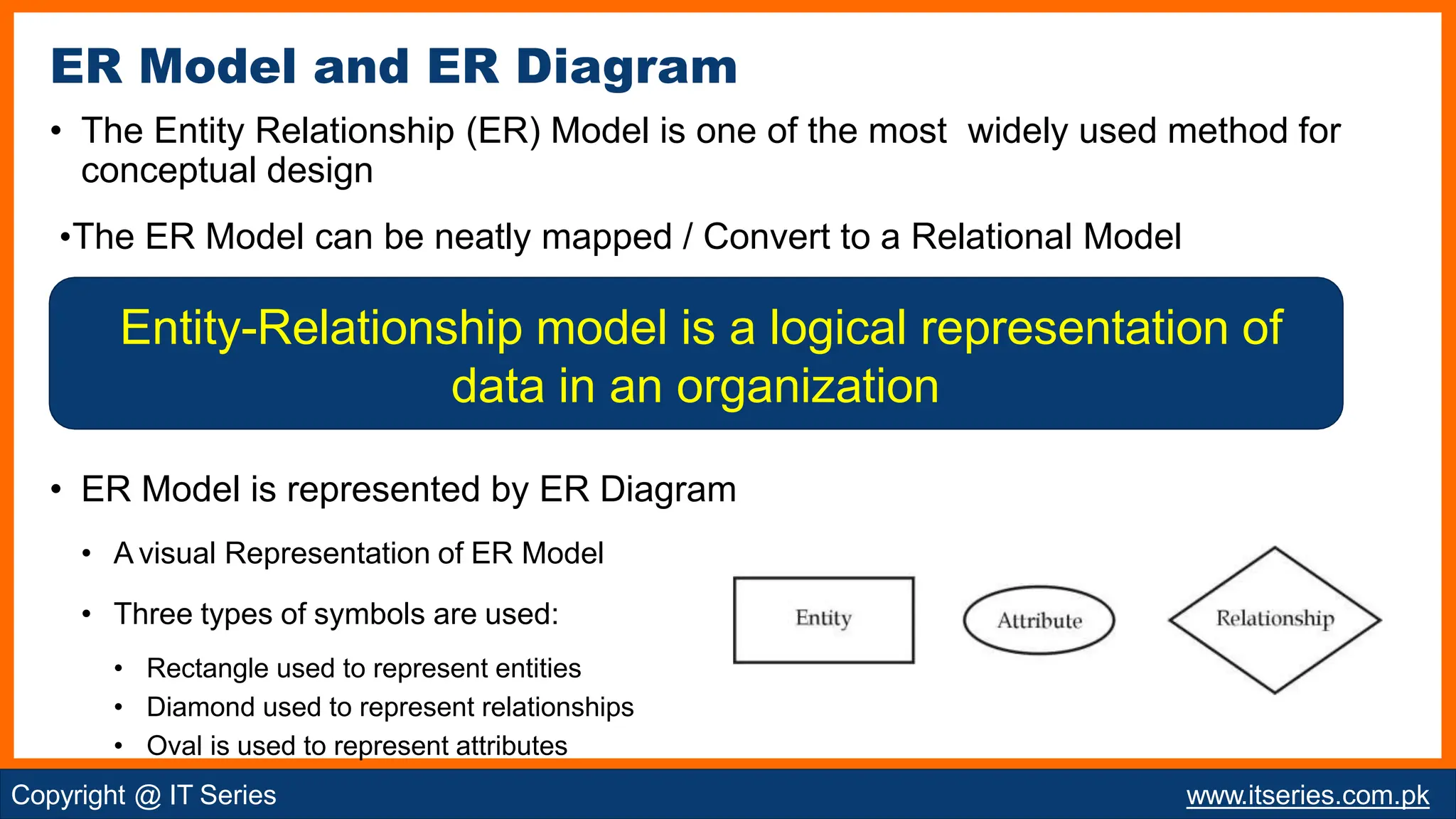
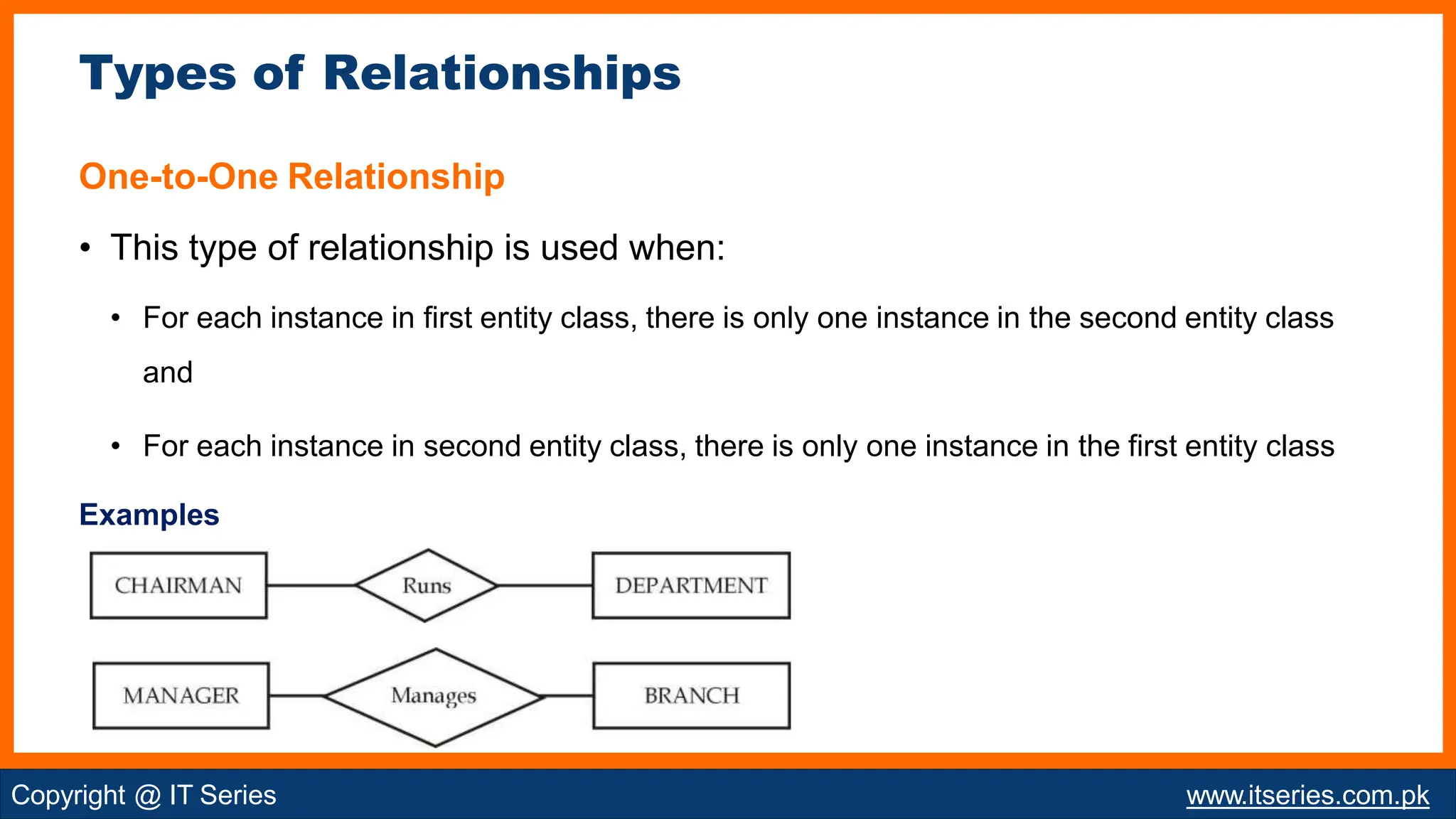
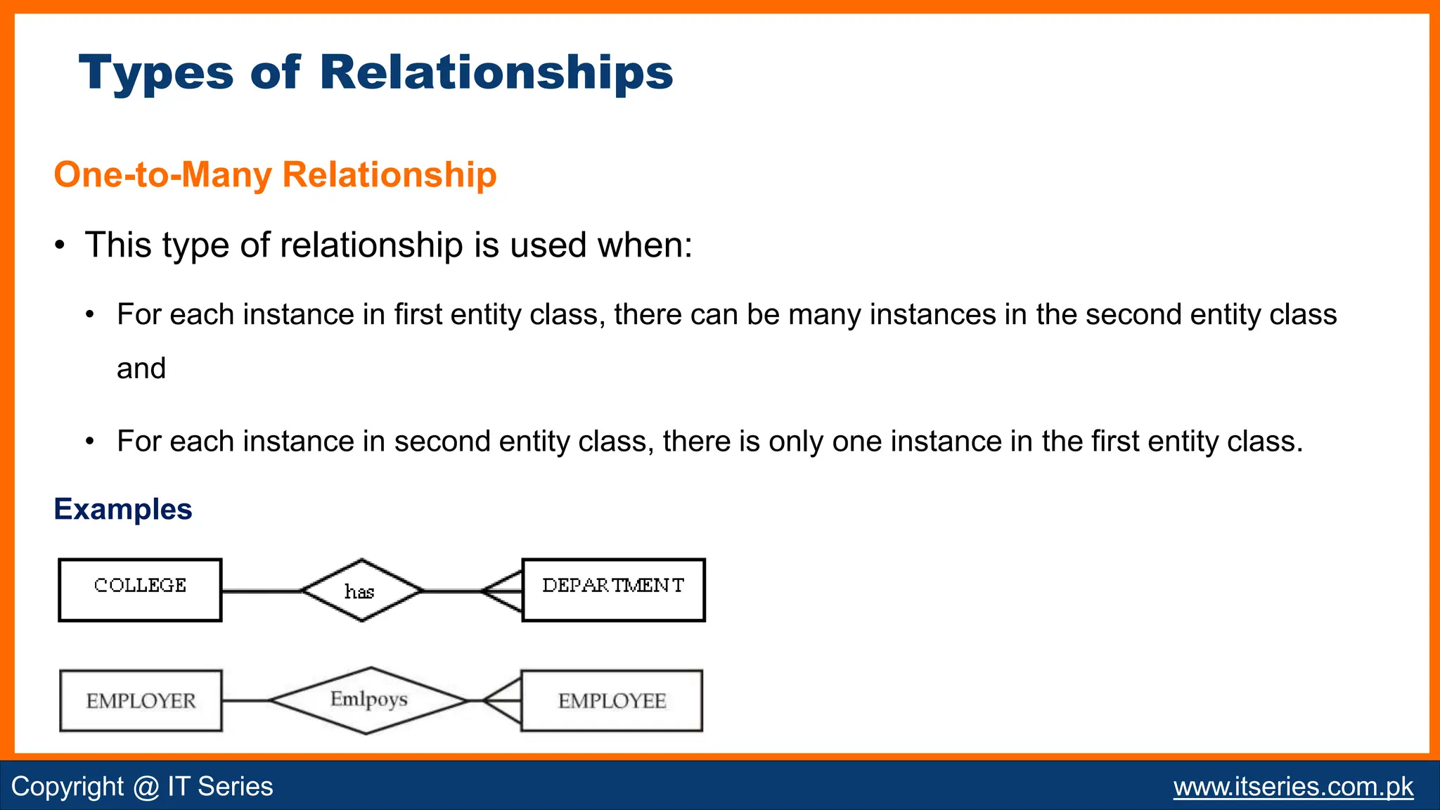
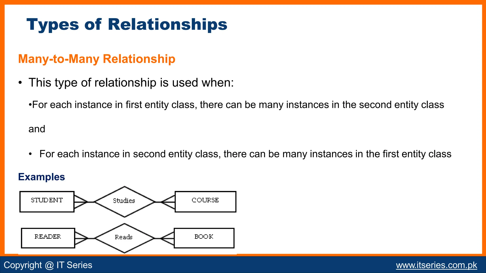
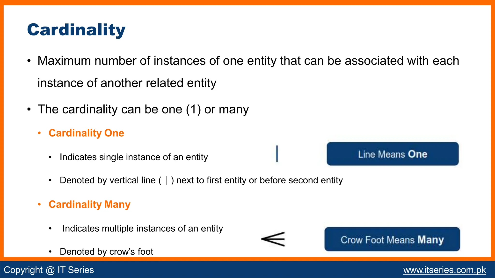
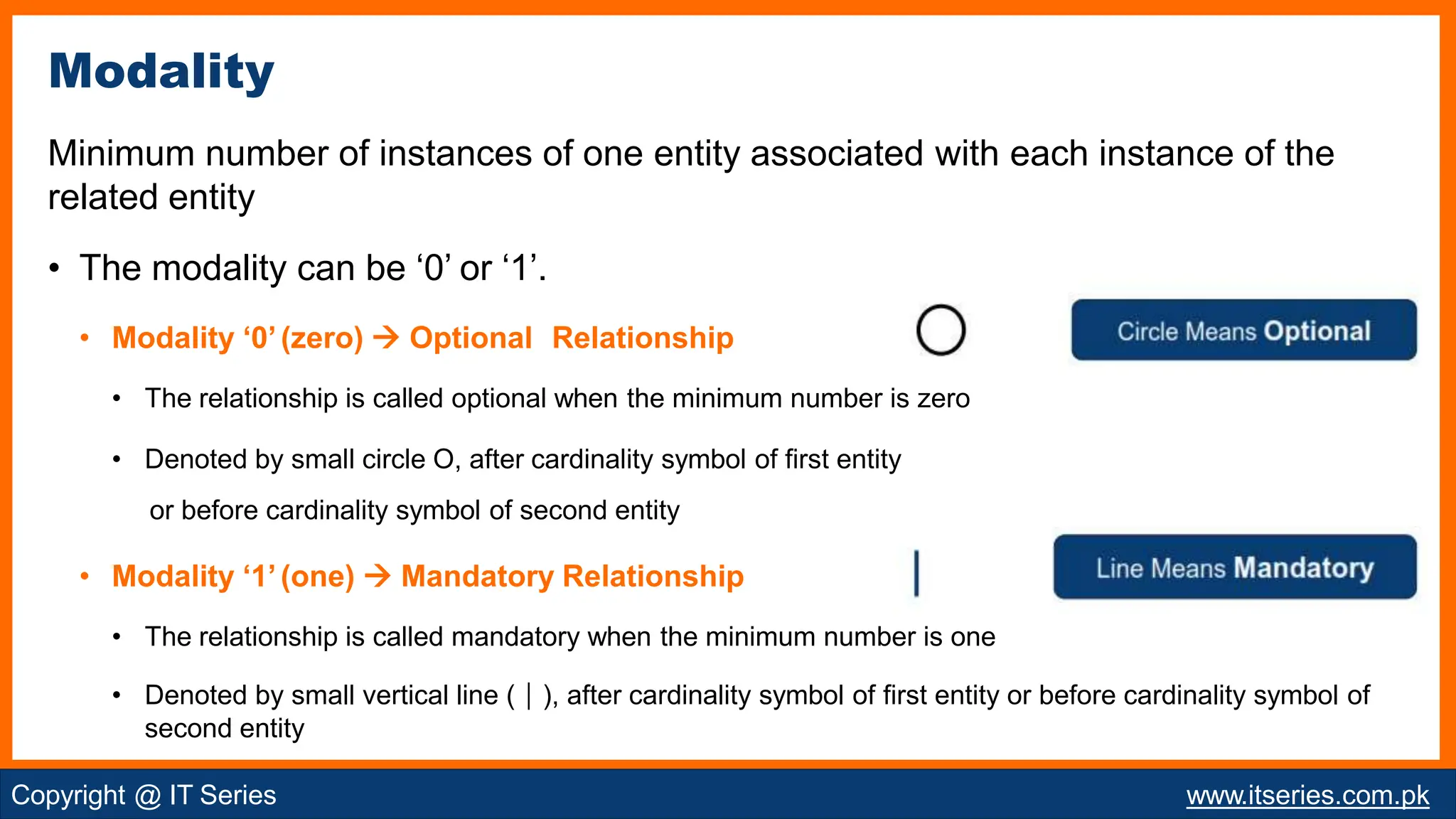
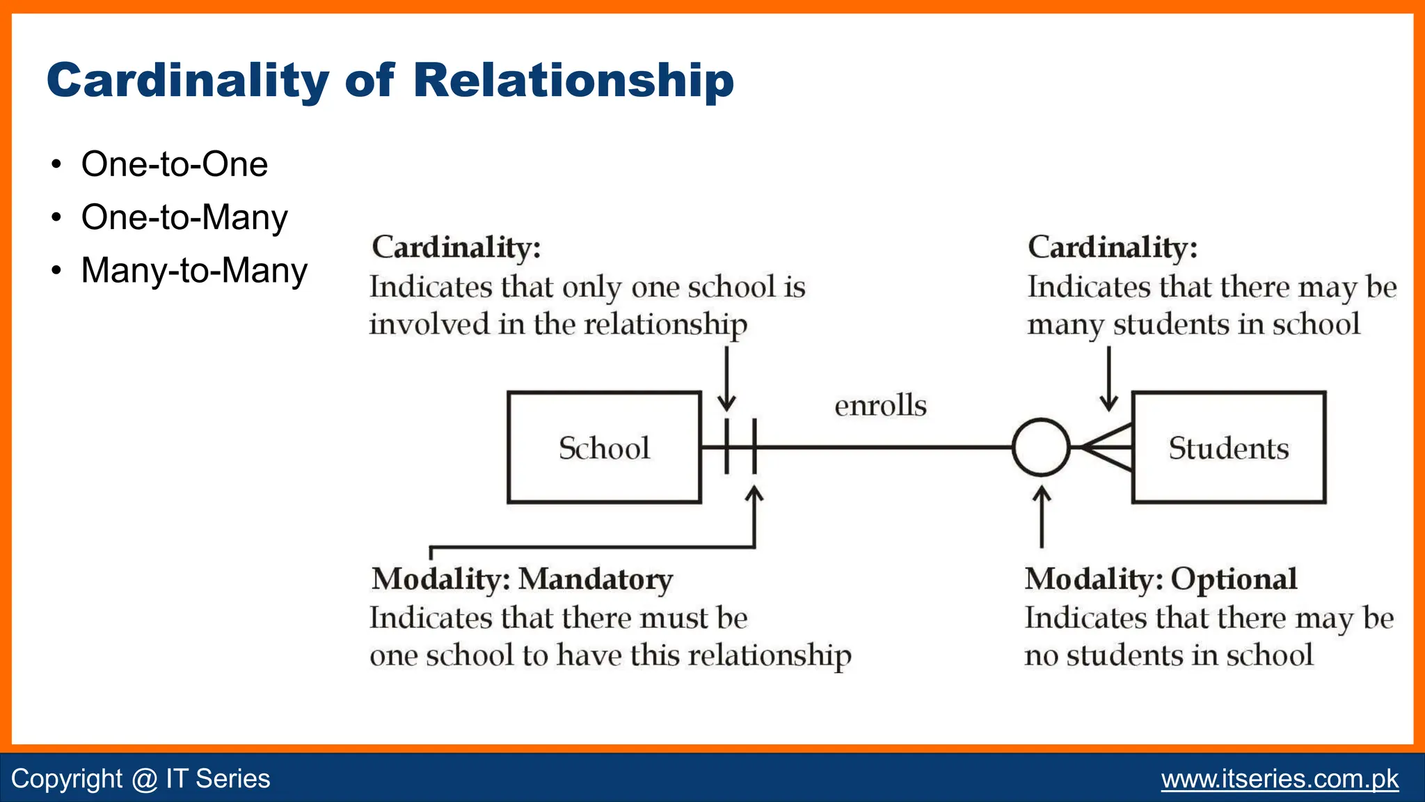
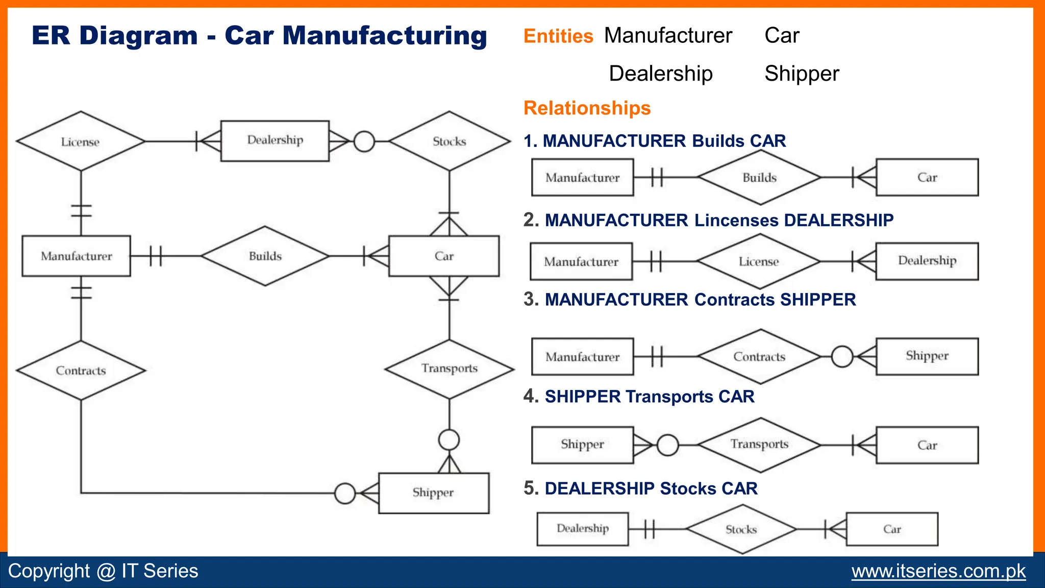
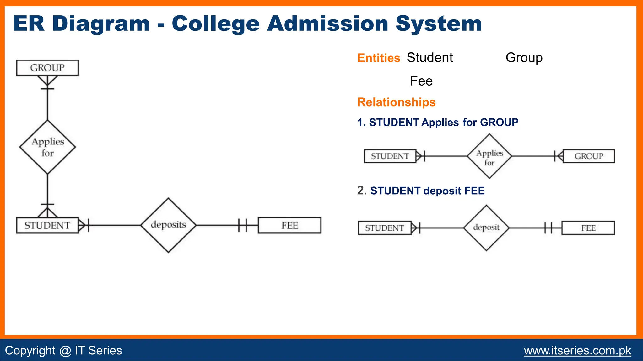
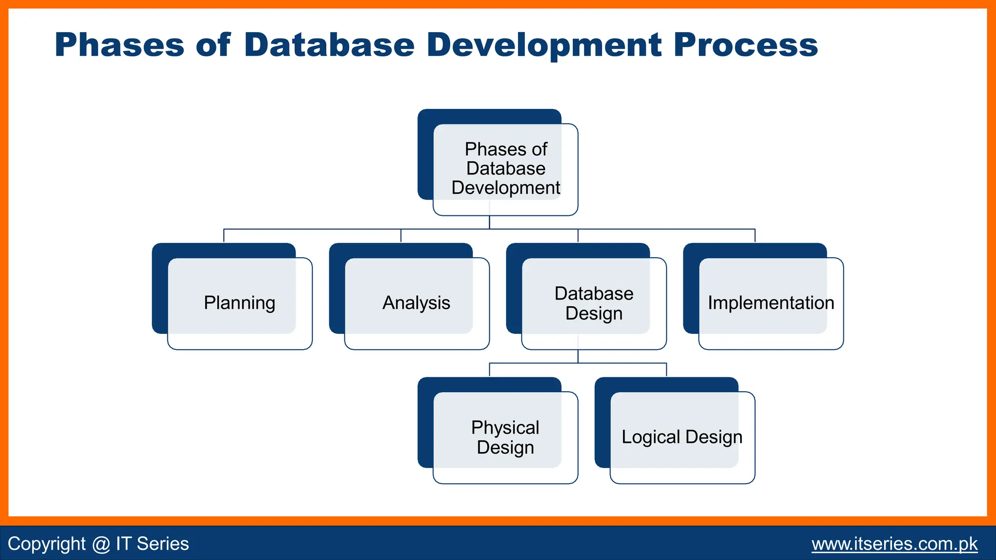
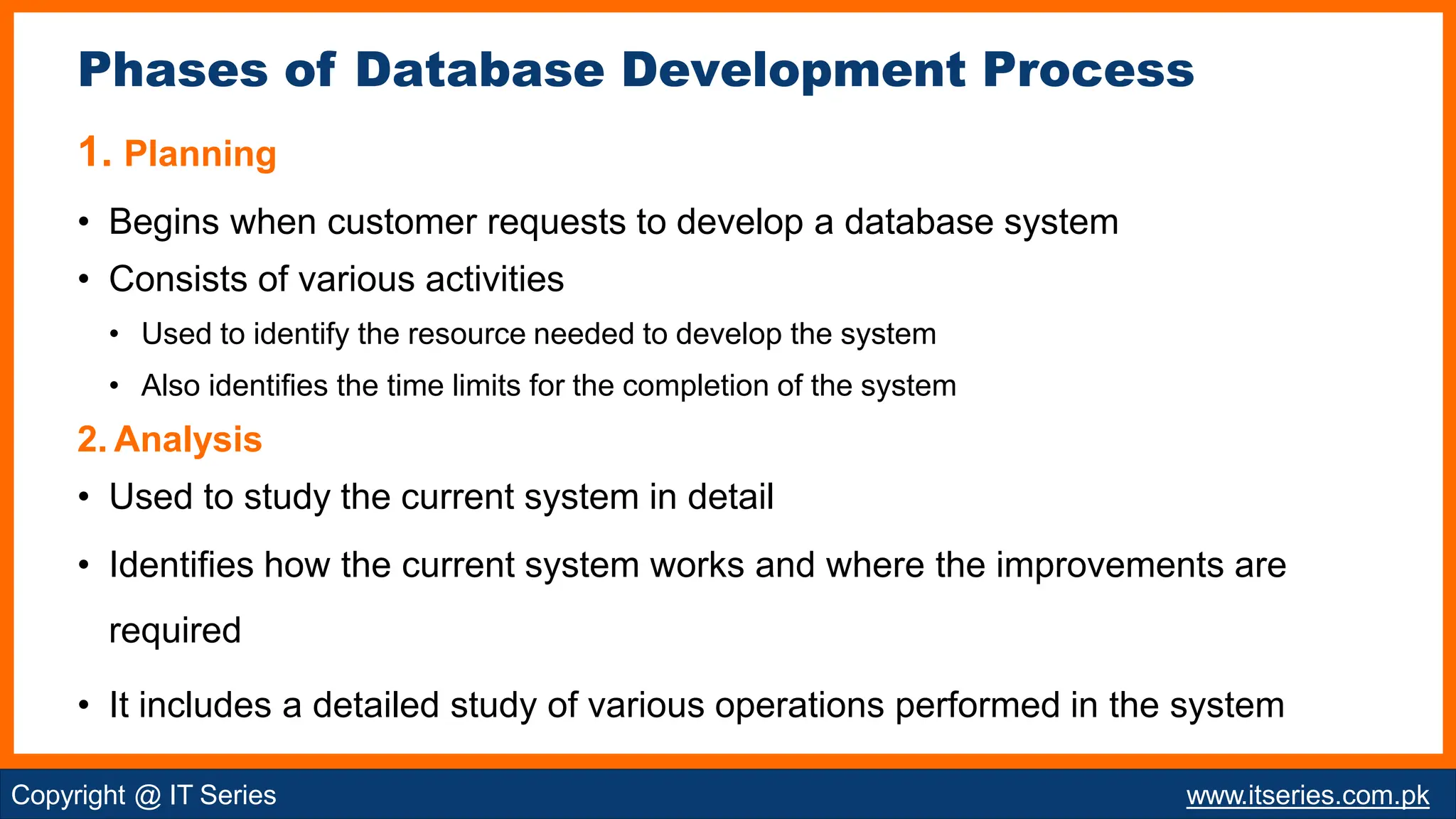
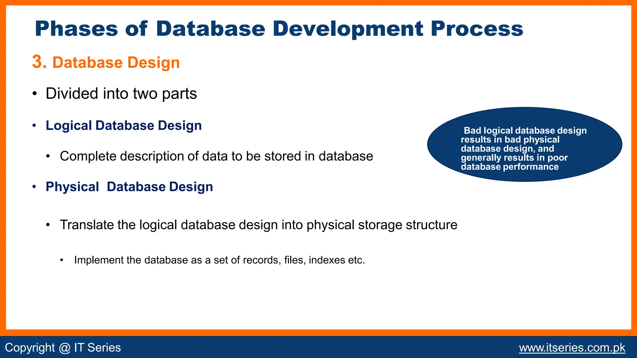
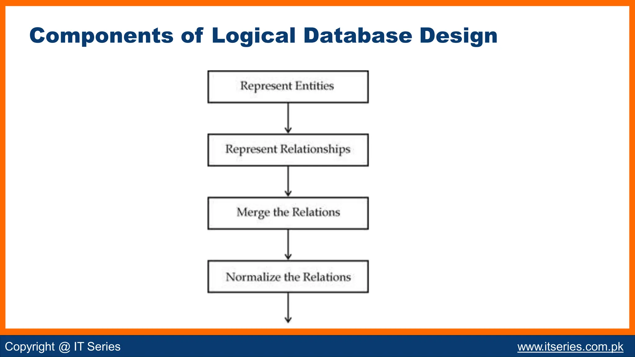
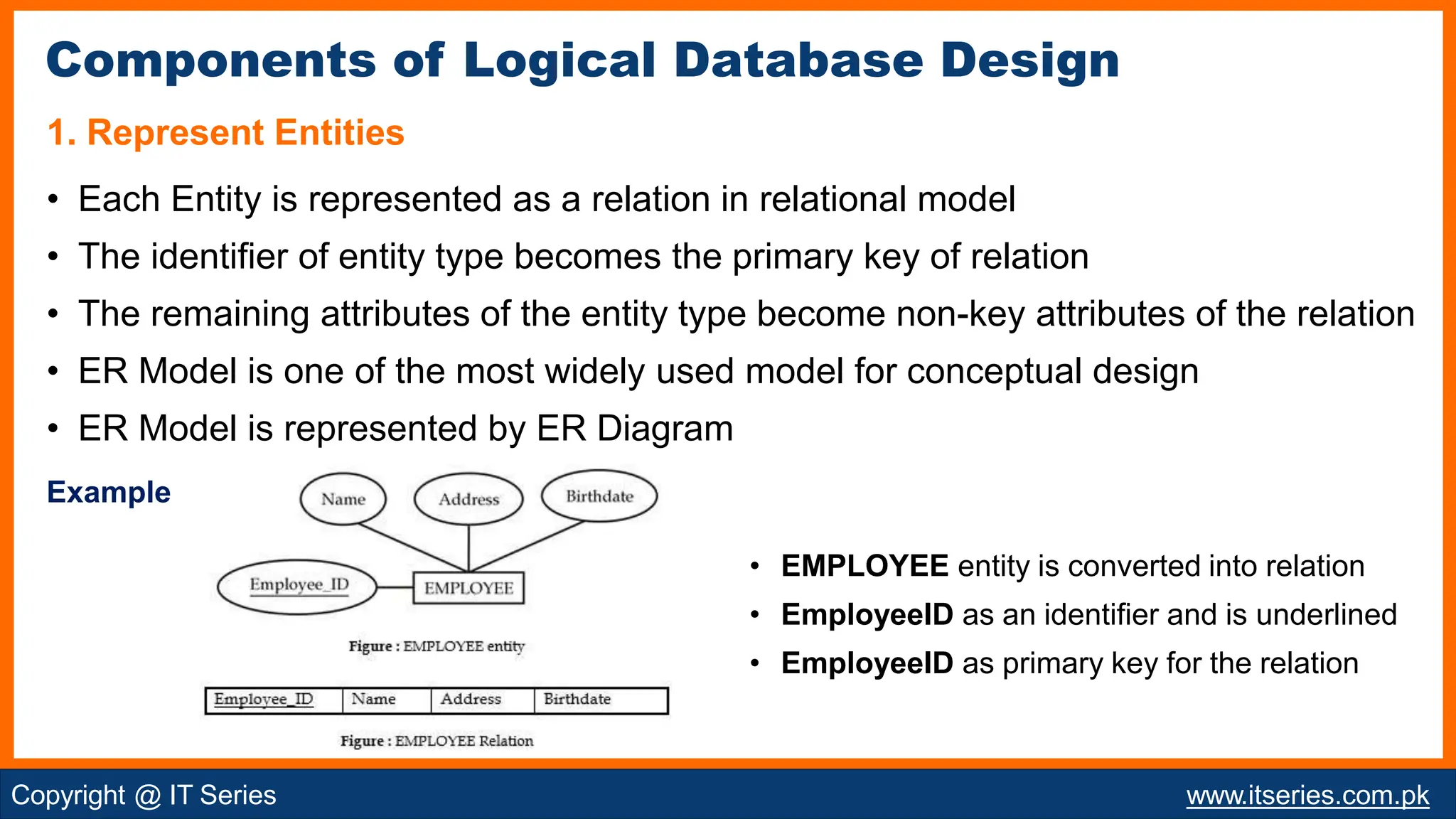
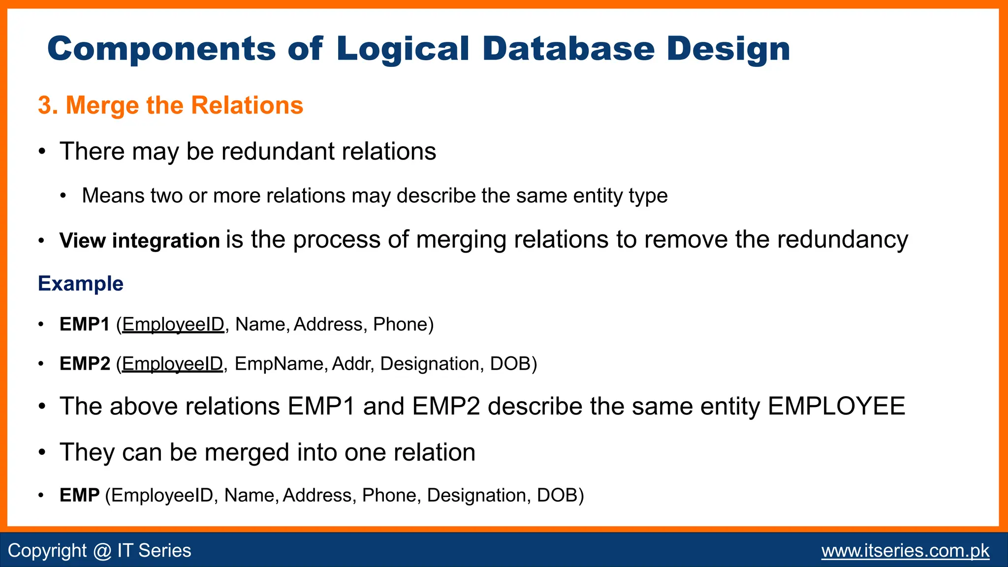
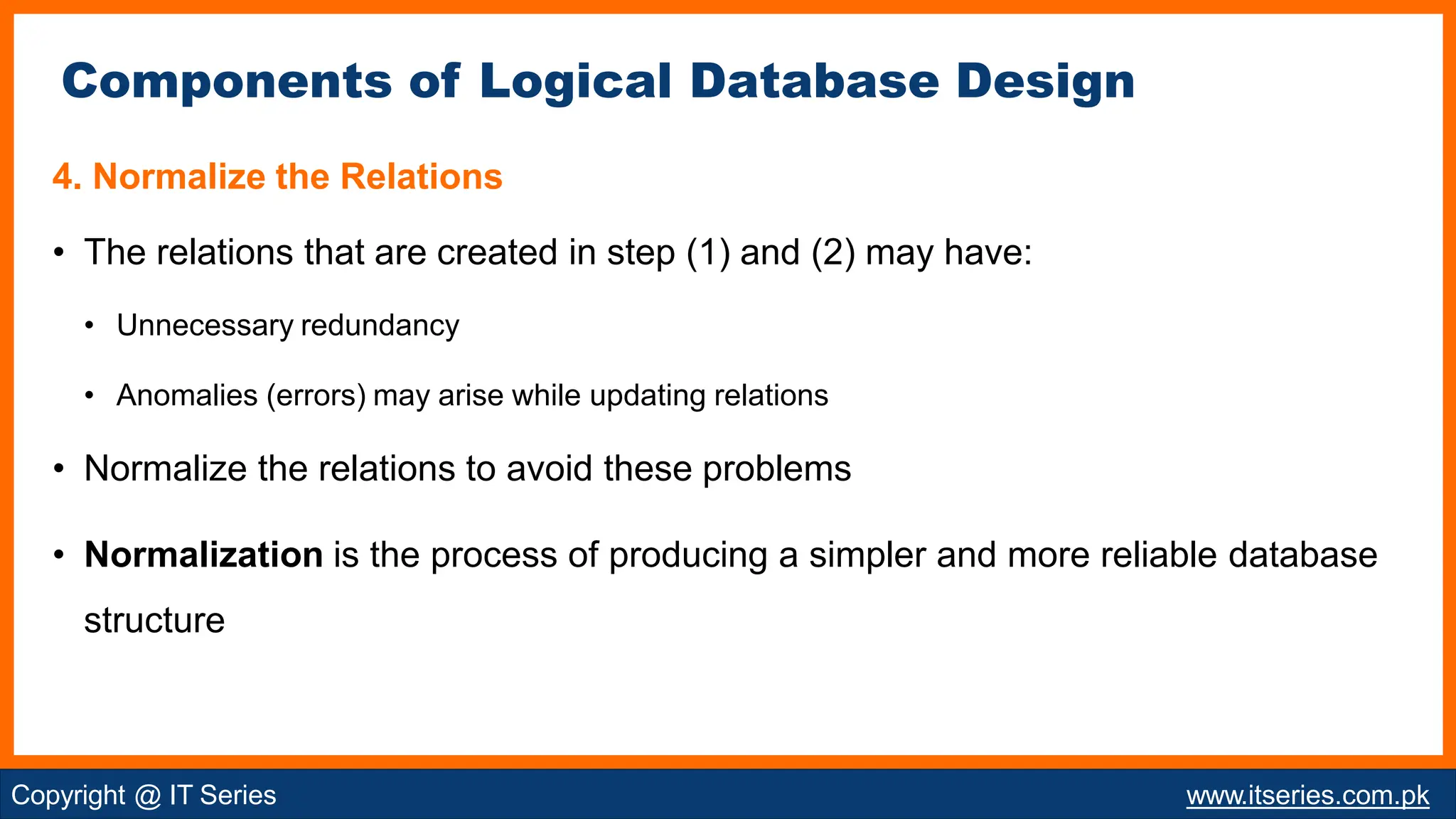
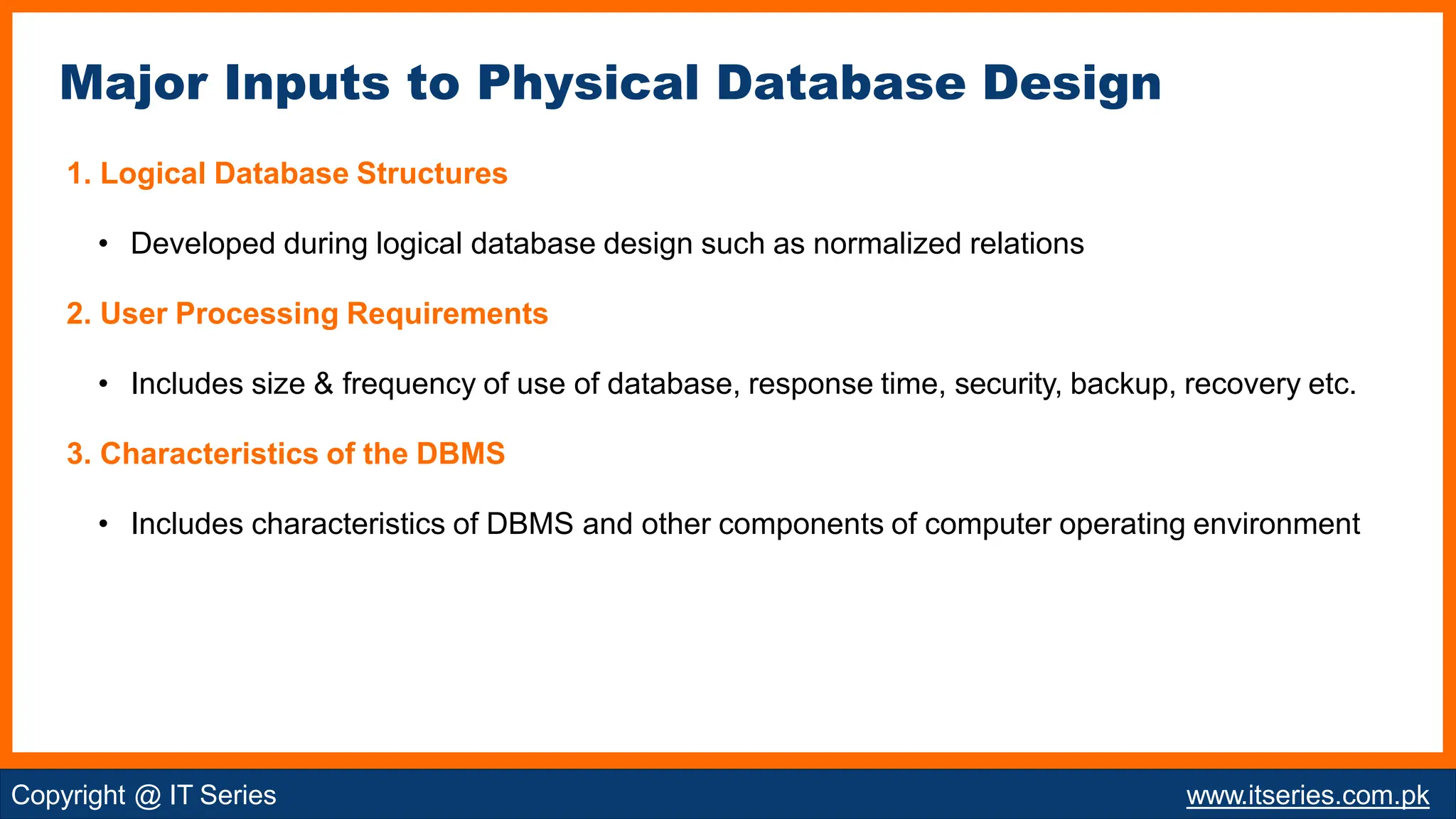
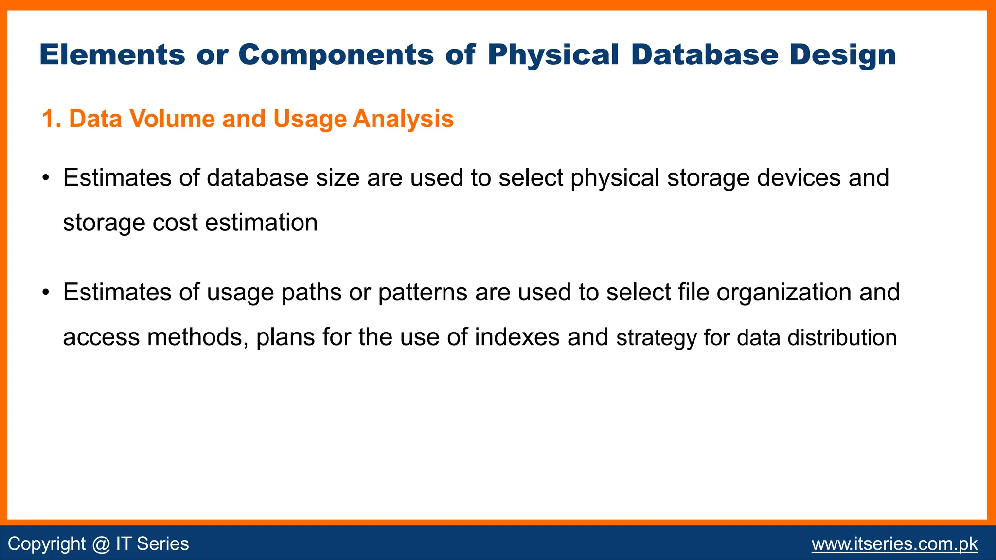
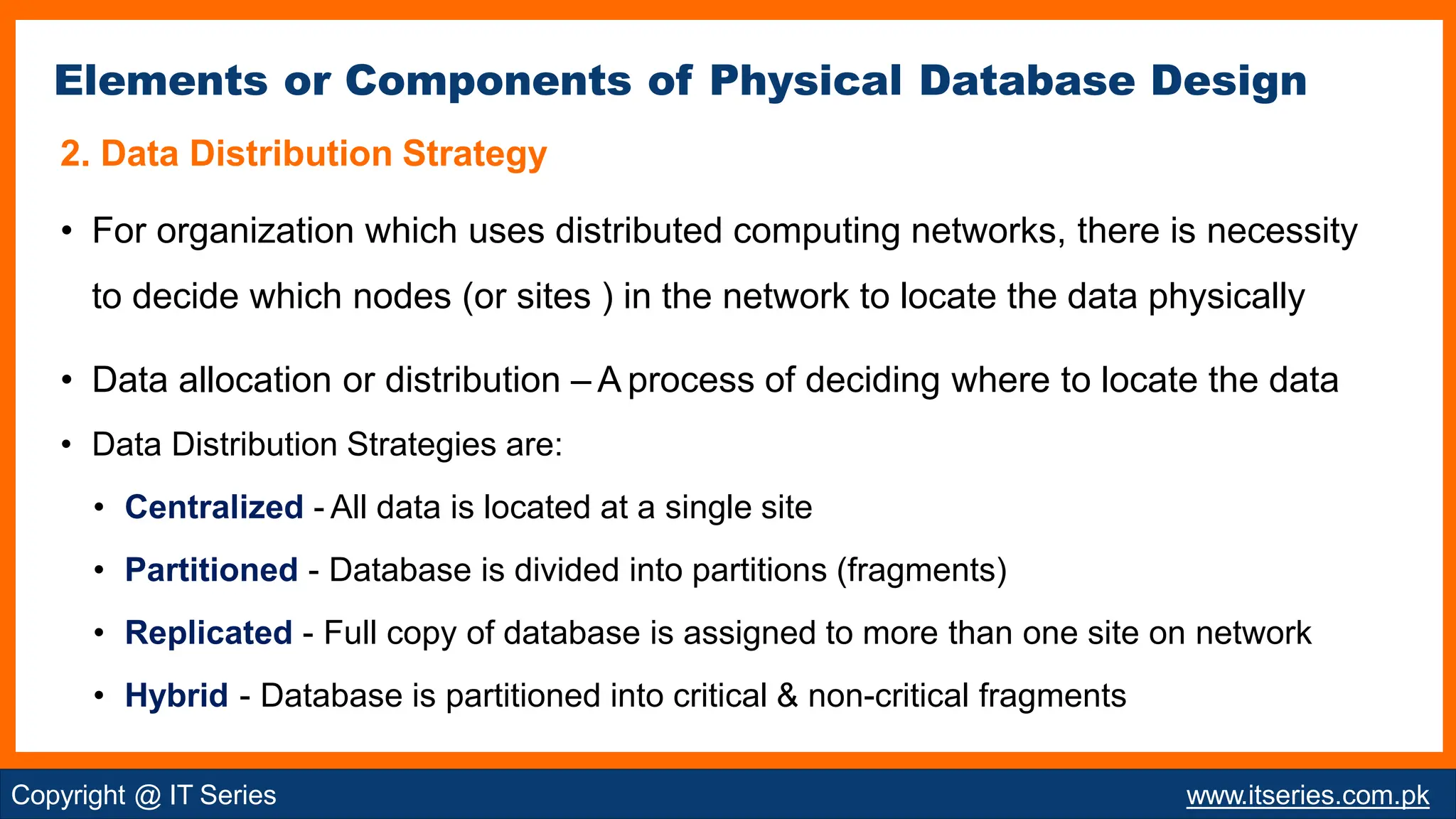
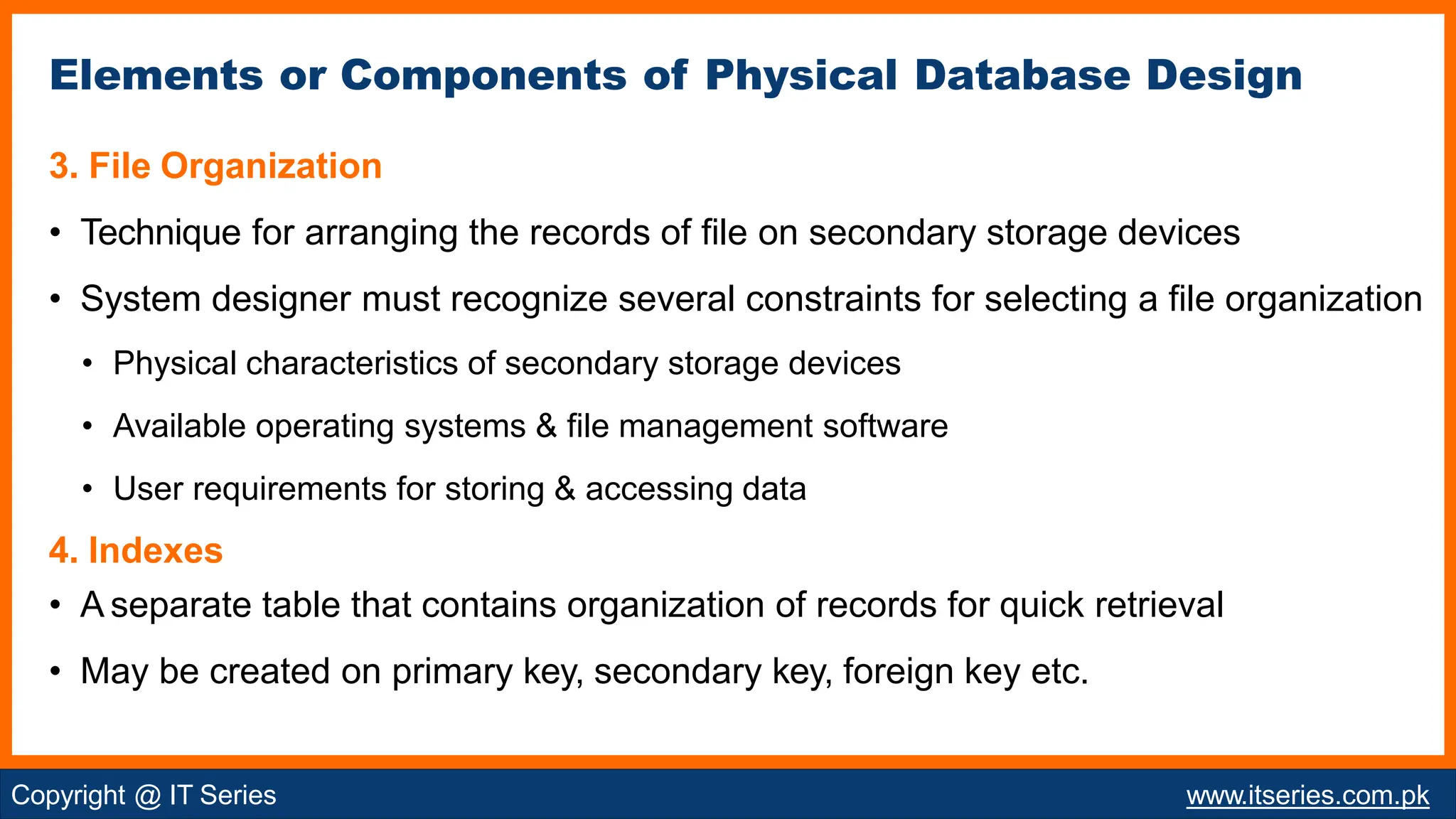
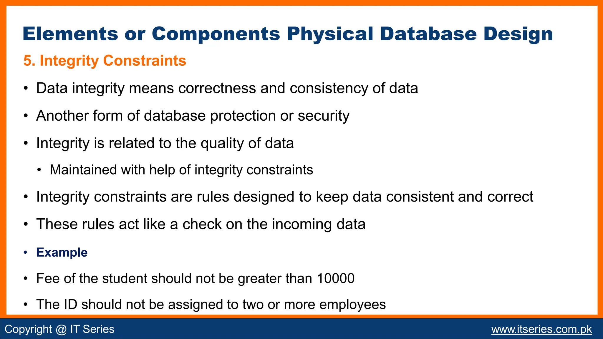
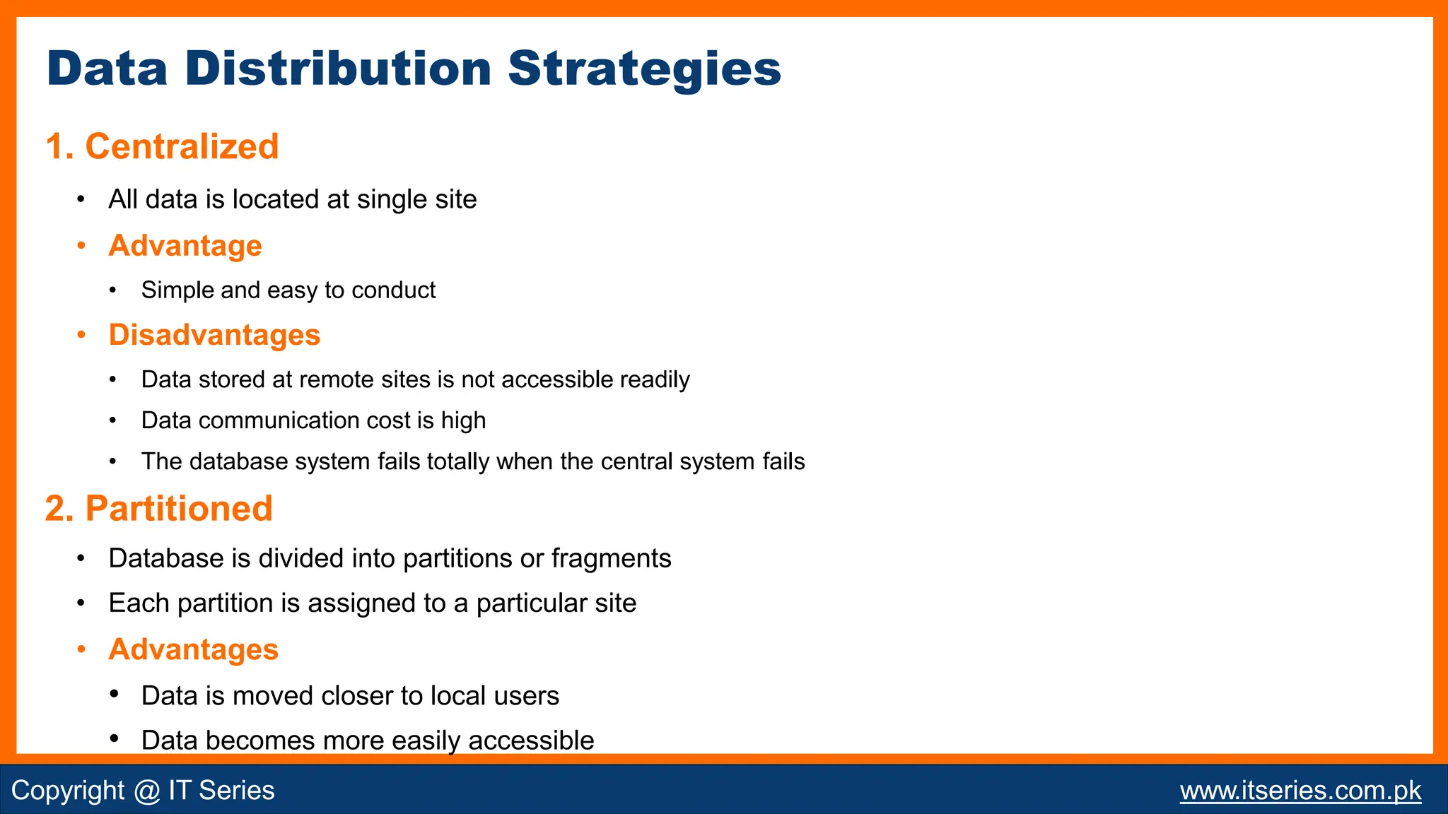
COMPUTER
SCIENC
E 12
(MS Access and C)
CHAPTER 3:
DATABASE DESIGN PROCESS
Copyright @ IT Series www.itseries.com.pk
• Analysis and Steps of Analysis Stage
• Data Modeling
• Entity Class & Instance
• Types of Relationships
• Cardinality & Modality
• ER Diagram
• Database Design Process
• Components of Logical Model
• Physical Database Design
• Components of Database Design
• Data Distribution Strategies
• File Organization
Copyright @ IT Series www.itseries.com.pk
Topics
• Process of Studying the existing system
• Basic purpose is to know which activities are performed in the current system
• Determines what should take place in the new system
Important Steps in Analysis Stage
• Feasibility Study
• Requirement Analysis
• Project Planning
• Data Analysis
Analysis and Steps of Analysis Stage
Feasibility
Study
Requirement
Analysis
Project Planning
Data Analysis
Copyright @ IT Series www.itseries.com.pk
Feasibility Study
• Conducted to investigate the required system
• Determines whether the proposed system is affordable, possible and acceptable
Requirement Analysis
• Collect the requirements for the project(proposed system) include:
• Possible inputs for database
• Required functionality of project
• The user describe their requirements and expectations from the proposed system
Copyright @ IT Series www.itseries.com.pk
Steps of Analysis Stage
Project Planning
• Comprehensive planning and time schedule must be developed to complete project
successfully
• Cost factors ( Hardware, Software, Salaries of Team ) are taken into consideration
Data Analysis
• Activities of data analysis
• Data Flow Diagrams
• Decision Tables
• Decision Trees
Copyright @ IT Series www.itseries.com.pk
Steps of Analysis Stage
Model - Representation of real world objects, events and their associations
Data Modeling - Process of identifying data objects and relationship between them
• E-R model is a popular conceptual data model
Data Modeling and its Ingredients
Ingredients of
Data
Modeling
Entity Attribute Relationship
Copyright @ IT Series www.itseries.com.pk
Entity
• Anything that is participating in the system is known as entity or object
• Can be person, place, thing or event
Examples
• Person: TEACHER,PLAYER
• Place: COUNTRY
• Object: VEHICAL
• Event: REGISTRAION,SALE, PURCHASE
• Represented by rectangle in data model
• Name of entity is written inside the rectangle
Ingredients of Data Modeling
Copyright @ IT Series www.itseries.com.pk
Attribute
• Characteristics of an entity
• Entity may have many attributes
Example
• Entity - TEACHER
• Attributes - Name, Gender, Last Degree, Appointment Date, Pay Scale , Telephone etc.
• Represented by an oval in the data model
• Name of entity is written inside the oval
Ingredients of Data Modeling
Copyright @ IT Series www.itseries.com.pk
• A BOOK STORE orders BOOK(s)
• A BOOK STORE displays BOOK(s)
• A BOOK STORE stocks
• A BOOK STORE sells
• A BOOK STORE returns
BOOK(s)
BOOK(s)
BOOK(s)
• All relationships define relevant connections between two entities
• All relationships are bi-directional
• Consider only relevant relationship
Relationship
• A logical connection between different entities
• Relationship indicates how the entities are related to each other
• Example
• Relationship between two entities BOOK and BOOK STORE
• Entities are connected with different ways
Ingredients of Data Modeling
Copyright @ IT Series www.itseries.com.pk
ER Model and ER Diagram
• The Entity Relationship (ER) Model is one of the most widely used method for
conceptual design
•The ER Model can be neatly mapped / Convert to a Relational Model
Entity-Relationship model is a logical representation of
data in an organization
• ER Model is represented by ER Diagram
• A visual Representation of ER Model
• Three types of symbols are used:
• Rectangle used to represent entities
• Diamond used to represent relationships
• Oval is used to represent attributes
Copyright @ IT Series www.itseries.com.pk
Entity Class
• A group of entities of the same type is called entity class
• It is also known as entity type
Example
• STUDENT entity class is a set of all students
Entity Instance
• A member if an entity class is called entity instance
• It is also known as entity occurrence
Example
• StudentAbdullah of STUDENT entity type is an entity instance.
Copyright @ IT Series www.itseries.com.pk
Entity Class & Instance
• Binary relationships exists between the instance of two entities.
Types of relationships
• One-to-One Relationship
• One-to-Many Relationship
• Many-to-Many Relationship
Copyright @ IT Series www.itseries.com.pk
Types of Relationships
One-to-One Relationship
• This type of relationship is used when:
• For each instance in first entity class, there is only one instance in the second entity class
and
• For each instance in second entity class, there is only one instance in the first entity class
Examples
Types of Relationships
Copyright @ IT Series www.itseries.com.pk
One-to-Many Relationship
• This type of relationship is used when:
• For each instance in first entity class, there can be many instances in the second entity class
and
• For each instance in second entity class, there is only one instance in the first entity class.
Examples
Types of Relationships
Copyright @ IT Series www.itseries.com.pk
Many-to-Many Relationship
• This type of relationship is used when:
•For each instance in first entity class, there can be many instances in the second entity class
and
• For each instance in second entity class, there can be many instances in the first entity class
Examples
Types of Relationships
Copyright @ IT Series www.itseries.com.pk
• Maximum number of instances of one entity that can be associated with each
instance of another related entity
• The cardinality can be one (1) or many
• Cardinality One
• Indicates single instance of an entity
• Denoted by vertical line () next to first entity or before second entity
• Cardinality Many
• Indicates multiple instances of an entity
• Denoted by crow’s foot
Cardinality
Copyright @ IT Series www.itseries.com.pk
Minimum number of instances of one entity associated with each instance of the
related entity
• The modality can be ‘0’ or ‘1’.
• Modality ‘0’(zero)  Optional Relationship
• The relationship is called optional when the minimum number is zero
• Denoted by small circle O, after cardinality symbol of first entity
or before cardinality symbol of second entity
• Modality ‘1’(one)  Mandatory Relationship
• The relationship is called mandatory when the minimum number is one
• Denoted by small vertical line (), after cardinality symbol of first entity or before cardinality symbol of
second entity
Modality
Copyright @ IT Series www.itseries.com.pk
• One-to-One
• One-to-Many
• Many-to-Many
Cardinality of Relationship
Copyright @ IT Series www.itseries.com.pk
ER Diagram - Car Manufacturing Car
Shipper
Entities Manufacturer
Dealership
Relationships
1. MANUFACTURER Builds CAR
2. MANUFACTURER Lincenses DEALERSHIP
3. MANUFACTURER Contracts SHIPPER
4. SHIPPER Transports CAR
5. DEALERSHIP Stocks CAR
Copyright @ IT Series www.itseries.com.pk
ER Diagram - College Admission System
Group
Copyright @ IT Series www.itseries.com.pk
Entities Student
Fee
Relationships
1. STUDENT Applies for GROUP
2. STUDENT deposit FEE
• Map the conceptual data model (ERD) to an implementation model
• A particular DBMS must be able to process this model
• Performance of DBMS must be acceptable to all users throughout the
organization
• Users also need to access the information quickly and easily
Copyright @ IT Series www.itseries.com.pk
Database Design Process
Phases of
Database
Development
Planning Analysis Database
Design
Physical
Design
Logical Design
Implementation
Copyright @ IT Series www.itseries.com.pk
Phases of Database Development Process
1. Planning
• Begins when customer requests to develop a database system
• Consists of various activities
• Used to identify the resource needed to develop the system
• Also identifies the time limits for the completion of the system
2. Analysis
• Used to study the current system in detail
• Identifies how the current system works and where the improvements are
required
• It includes a detailed study of various operations performed in the system
Copyright @ IT Series www.itseries.com.pk
Phases of Database Development Process
3. Database Design
• Divided into two parts
• Logical Database Design
• Complete description of data to be stored in database
• Physical Database Design
• Translate the logical database design into physical storage structure
• Implement the database as a set of records, files, indexes etc.
Phases of Database Development Process
Bad logical database design
results in bad physical
database design, and
generally results in poor
database performance
Copyright @ IT Series www.itseries.com.pk
4. Implementation
• Database System is implemented after design and developed
• Database system installed and executed for the user
• It may require a particular type of computer like server
• May require network hardware if accessed at multiple locations
• Users are provided authorization by managers
• Example of NADRA & CRICKINFO
Copyright @ IT Series www.itseries.com.pk
Phases of Database Development Process
Components of Logical Database Design
Copyright @ IT Series www.itseries.com.pk
Components of Logical Database Design
1. Represent Entities
• Each Entity is represented as a relation in relational model
• The identifier of entity type becomes the primary key of relation
• The remaining attributes of the entity type become non-key attributes of the relation
• ER Model is one of the most widely used model for conceptual design
• ER Model is represented by ER Diagram
Example
• EMPLOYEE entity is converted into relation
• EmployeeID as an identifier and is underlined
• EmployeeID as primary key for the relation
Copyright @ IT Series www.itseries.com.pk
2. Represent Relationships
• Each relationship in an ER diagram must be represented in relational model
• Depends upon nature of relationship
• Represent a relationship by making primary key of one relation a foreign key of another
relation
• Create a separate relation to represent a relationship
Copyright @ IT Series www.itseries.com.pk
Components of Logical Database Design
3. Merge the Relations
• There may be redundant relations
• Means two or more relations may describe the same entity type
• View integration is the process of merging relations to remove the redundancy
Example
• EMP1 (EmployeeID, Name, Address, Phone)
• EMP2 (EmployeeID, EmpName, Addr, Designation, DOB)
• The above relations EMP1 and EMP2 describe the same entity EMPLOYEE
• They can be merged into one relation
• EMP (EmployeeID, Name, Address, Phone, Designation, DOB)
Copyright @ IT Series www.itseries.com.pk
Components of Logical Database Design
4. Normalize the Relations
• The relations that are created in step (1) and (2) may have:
• Unnecessary redundancy
• Anomalies (errors) may arise while updating relations
• Normalize the relations to avoid these problems
• Normalization is the process of producing a simpler and more reliable database
structure
Copyright @ IT Series www.itseries.com.pk
Components of Logical Database Design
• Last stage of database design process
• A process of mapping logical database structure into actual database
structure:
• Set of records
• Files
• Indexes etc.
Copyright @ IT Series www.itseries.com.pk
Physical Database Design
Major Inputs to Physical Database Design
Copyright @ IT Series www.itseries.com.pk
1. Logical Database Structures
• Developed during logical database design such as normalized relations
2. User Processing Requirements
• Includes size & frequency of use of database, response time, security, backup, recovery etc.
3. Characteristics of the DBMS
• Includes characteristics of DBMS and other components of computer operating environment
1. Data Volume and Usage Analysis
• Estimates of database size are used to select physical storage devices and
storage cost estimation
• Estimates of usage paths or patterns are used to select file organization and
access methods, plans for the use of indexes and strategy for data distribution
Copyright @ IT Series www.itseries.com.pk
Elements or Components of Physical Database Design
2. Data Distribution Strategy
• For organization which uses distributed computing networks, there is necessity
to decide which nodes (or sites ) in the network to locate the data physically
• Data allocation or distribution – A process of deciding where to locate the data
• Data Distribution Strategies are:
• Centralized - All data is located at a single site
• Partitioned - Database is divided into partitions (fragments)
• Replicated - Full copy of database is assigned to more than one site on network
• Hybrid - Database is partitioned into critical & non-critical fragments
Copyright @ IT Series www.itseries.com.pk
Elements or Components of Physical Database Design
3. File Organization
• Technique for arranging the records of file on secondary storage devices
• System designer must recognize several constraints for selecting a file organization
• Physical characteristics of secondary storage devices
• Available operating systems & file management software
• User requirements for storing & accessing data
4. Indexes
• A separate table that contains organization of records for quick retrieval
• May be created on primary key, secondary key, foreign key etc.
Copyright @ IT Series www.itseries.com.pk
Elements or Components of Physical Database Design
5. Integrity Constraints
• Data integrity means correctness and consistency of data
• Another form of database protection or security
• Integrity is related to the quality of data
• Maintained with help of integrity constraints
• Integrity constraints are rules designed to keep data consistent and correct
• These rules act like a check on the incoming data
• Example
• Fee of the student should not be greater than 10000
• The ID should not be assigned to two or more employees
Copyright @ IT Series www.itseries.com.pk
Elements or Components Physical Database Design
1. Centralized
• All data is located at single site
• Advantage
• Simple and easy to conduct
• Disadvantages
• Data stored at remote sites is not accessible readily
• Data communication cost is high
• The database system fails totally when the central system fails
2. Partitioned
• Database is divided into partitions or fragments
• Each partition is assigned to a particular site
• Advantages
• Data is moved closer to local users
• Data becomes more easily accessible
Copyright @ IT Series www.itseries.com.pk
Data Distribution Strategies
3. Replicated
• Full Copy of database is assigned to more than one site in the network
• This strategy maximizes local access but it creates update problems
4. Hybrid
• Database is divided into critical and non critical fragments
• Critical fragments are stored at multiple sites
• Non Critical fragments are stored at one site only
Copyright @ IT Series www.itseries.com.pk
Data Distribution Strategies
Copyright @ IT Series www.itseries.com.pk

DATA BASE DESIGN PROCESS CHAPTER NO 3 COMPUTER SCIENCE

  • 1.
    COMPUTER SCIENC E 12 (MS Accessand C) CHAPTER 3: DATABASE DESIGN PROCESS Copyright @ IT Series www.itseries.com.pk
  • 2.
    • Analysis andSteps of Analysis Stage • Data Modeling • Entity Class & Instance • Types of Relationships • Cardinality & Modality • ER Diagram • Database Design Process • Components of Logical Model • Physical Database Design • Components of Database Design • Data Distribution Strategies • File Organization Copyright @ IT Series www.itseries.com.pk Topics
  • 3.
    • Process ofStudying the existing system • Basic purpose is to know which activities are performed in the current system • Determines what should take place in the new system Important Steps in Analysis Stage • Feasibility Study • Requirement Analysis • Project Planning • Data Analysis Analysis and Steps of Analysis Stage Feasibility Study Requirement Analysis Project Planning Data Analysis Copyright @ IT Series www.itseries.com.pk
  • 4.
    Feasibility Study • Conductedto investigate the required system • Determines whether the proposed system is affordable, possible and acceptable Requirement Analysis • Collect the requirements for the project(proposed system) include: • Possible inputs for database • Required functionality of project • The user describe their requirements and expectations from the proposed system Copyright @ IT Series www.itseries.com.pk Steps of Analysis Stage
  • 5.
    Project Planning • Comprehensiveplanning and time schedule must be developed to complete project successfully • Cost factors ( Hardware, Software, Salaries of Team ) are taken into consideration Data Analysis • Activities of data analysis • Data Flow Diagrams • Decision Tables • Decision Trees Copyright @ IT Series www.itseries.com.pk Steps of Analysis Stage
  • 6.
    Model - Representationof real world objects, events and their associations Data Modeling - Process of identifying data objects and relationship between them • E-R model is a popular conceptual data model Data Modeling and its Ingredients Ingredients of Data Modeling Entity Attribute Relationship Copyright @ IT Series www.itseries.com.pk
  • 7.
    Entity • Anything thatis participating in the system is known as entity or object • Can be person, place, thing or event Examples • Person: TEACHER,PLAYER • Place: COUNTRY • Object: VEHICAL • Event: REGISTRAION,SALE, PURCHASE • Represented by rectangle in data model • Name of entity is written inside the rectangle Ingredients of Data Modeling Copyright @ IT Series www.itseries.com.pk
  • 8.
    Attribute • Characteristics ofan entity • Entity may have many attributes Example • Entity - TEACHER • Attributes - Name, Gender, Last Degree, Appointment Date, Pay Scale , Telephone etc. • Represented by an oval in the data model • Name of entity is written inside the oval Ingredients of Data Modeling Copyright @ IT Series www.itseries.com.pk
  • 9.
    • A BOOKSTORE orders BOOK(s) • A BOOK STORE displays BOOK(s) • A BOOK STORE stocks • A BOOK STORE sells • A BOOK STORE returns BOOK(s) BOOK(s) BOOK(s) • All relationships define relevant connections between two entities • All relationships are bi-directional • Consider only relevant relationship Relationship • A logical connection between different entities • Relationship indicates how the entities are related to each other • Example • Relationship between two entities BOOK and BOOK STORE • Entities are connected with different ways Ingredients of Data Modeling Copyright @ IT Series www.itseries.com.pk
  • 10.
    ER Model andER Diagram • The Entity Relationship (ER) Model is one of the most widely used method for conceptual design •The ER Model can be neatly mapped / Convert to a Relational Model Entity-Relationship model is a logical representation of data in an organization • ER Model is represented by ER Diagram • A visual Representation of ER Model • Three types of symbols are used: • Rectangle used to represent entities • Diamond used to represent relationships • Oval is used to represent attributes Copyright @ IT Series www.itseries.com.pk
  • 11.
    Entity Class • Agroup of entities of the same type is called entity class • It is also known as entity type Example • STUDENT entity class is a set of all students Entity Instance • A member if an entity class is called entity instance • It is also known as entity occurrence Example • StudentAbdullah of STUDENT entity type is an entity instance. Copyright @ IT Series www.itseries.com.pk Entity Class & Instance
  • 12.
    • Binary relationshipsexists between the instance of two entities. Types of relationships • One-to-One Relationship • One-to-Many Relationship • Many-to-Many Relationship Copyright @ IT Series www.itseries.com.pk Types of Relationships
  • 13.
    One-to-One Relationship • Thistype of relationship is used when: • For each instance in first entity class, there is only one instance in the second entity class and • For each instance in second entity class, there is only one instance in the first entity class Examples Types of Relationships Copyright @ IT Series www.itseries.com.pk
  • 14.
    One-to-Many Relationship • Thistype of relationship is used when: • For each instance in first entity class, there can be many instances in the second entity class and • For each instance in second entity class, there is only one instance in the first entity class. Examples Types of Relationships Copyright @ IT Series www.itseries.com.pk
  • 15.
    Many-to-Many Relationship • Thistype of relationship is used when: •For each instance in first entity class, there can be many instances in the second entity class and • For each instance in second entity class, there can be many instances in the first entity class Examples Types of Relationships Copyright @ IT Series www.itseries.com.pk
  • 16.
    • Maximum numberof instances of one entity that can be associated with each instance of another related entity • The cardinality can be one (1) or many • Cardinality One • Indicates single instance of an entity • Denoted by vertical line () next to first entity or before second entity • Cardinality Many • Indicates multiple instances of an entity • Denoted by crow’s foot Cardinality Copyright @ IT Series www.itseries.com.pk
  • 17.
    Minimum number ofinstances of one entity associated with each instance of the related entity • The modality can be ‘0’ or ‘1’. • Modality ‘0’(zero)  Optional Relationship • The relationship is called optional when the minimum number is zero • Denoted by small circle O, after cardinality symbol of first entity or before cardinality symbol of second entity • Modality ‘1’(one)  Mandatory Relationship • The relationship is called mandatory when the minimum number is one • Denoted by small vertical line (), after cardinality symbol of first entity or before cardinality symbol of second entity Modality Copyright @ IT Series www.itseries.com.pk
  • 18.
    • One-to-One • One-to-Many •Many-to-Many Cardinality of Relationship Copyright @ IT Series www.itseries.com.pk
  • 19.
    ER Diagram -Car Manufacturing Car Shipper Entities Manufacturer Dealership Relationships 1. MANUFACTURER Builds CAR 2. MANUFACTURER Lincenses DEALERSHIP 3. MANUFACTURER Contracts SHIPPER 4. SHIPPER Transports CAR 5. DEALERSHIP Stocks CAR Copyright @ IT Series www.itseries.com.pk
  • 20.
    ER Diagram -College Admission System Group Copyright @ IT Series www.itseries.com.pk Entities Student Fee Relationships 1. STUDENT Applies for GROUP 2. STUDENT deposit FEE
  • 21.
    • Map theconceptual data model (ERD) to an implementation model • A particular DBMS must be able to process this model • Performance of DBMS must be acceptable to all users throughout the organization • Users also need to access the information quickly and easily Copyright @ IT Series www.itseries.com.pk Database Design Process
  • 22.
    Phases of Database Development Planning AnalysisDatabase Design Physical Design Logical Design Implementation Copyright @ IT Series www.itseries.com.pk Phases of Database Development Process
  • 23.
    1. Planning • Beginswhen customer requests to develop a database system • Consists of various activities • Used to identify the resource needed to develop the system • Also identifies the time limits for the completion of the system 2. Analysis • Used to study the current system in detail • Identifies how the current system works and where the improvements are required • It includes a detailed study of various operations performed in the system Copyright @ IT Series www.itseries.com.pk Phases of Database Development Process
  • 24.
    3. Database Design •Divided into two parts • Logical Database Design • Complete description of data to be stored in database • Physical Database Design • Translate the logical database design into physical storage structure • Implement the database as a set of records, files, indexes etc. Phases of Database Development Process Bad logical database design results in bad physical database design, and generally results in poor database performance Copyright @ IT Series www.itseries.com.pk
  • 25.
    4. Implementation • DatabaseSystem is implemented after design and developed • Database system installed and executed for the user • It may require a particular type of computer like server • May require network hardware if accessed at multiple locations • Users are provided authorization by managers • Example of NADRA & CRICKINFO Copyright @ IT Series www.itseries.com.pk Phases of Database Development Process
  • 26.
    Components of LogicalDatabase Design Copyright @ IT Series www.itseries.com.pk
  • 27.
    Components of LogicalDatabase Design 1. Represent Entities • Each Entity is represented as a relation in relational model • The identifier of entity type becomes the primary key of relation • The remaining attributes of the entity type become non-key attributes of the relation • ER Model is one of the most widely used model for conceptual design • ER Model is represented by ER Diagram Example • EMPLOYEE entity is converted into relation • EmployeeID as an identifier and is underlined • EmployeeID as primary key for the relation Copyright @ IT Series www.itseries.com.pk
  • 28.
    2. Represent Relationships •Each relationship in an ER diagram must be represented in relational model • Depends upon nature of relationship • Represent a relationship by making primary key of one relation a foreign key of another relation • Create a separate relation to represent a relationship Copyright @ IT Series www.itseries.com.pk Components of Logical Database Design
  • 29.
    3. Merge theRelations • There may be redundant relations • Means two or more relations may describe the same entity type • View integration is the process of merging relations to remove the redundancy Example • EMP1 (EmployeeID, Name, Address, Phone) • EMP2 (EmployeeID, EmpName, Addr, Designation, DOB) • The above relations EMP1 and EMP2 describe the same entity EMPLOYEE • They can be merged into one relation • EMP (EmployeeID, Name, Address, Phone, Designation, DOB) Copyright @ IT Series www.itseries.com.pk Components of Logical Database Design
  • 30.
    4. Normalize theRelations • The relations that are created in step (1) and (2) may have: • Unnecessary redundancy • Anomalies (errors) may arise while updating relations • Normalize the relations to avoid these problems • Normalization is the process of producing a simpler and more reliable database structure Copyright @ IT Series www.itseries.com.pk Components of Logical Database Design
  • 31.
    • Last stageof database design process • A process of mapping logical database structure into actual database structure: • Set of records • Files • Indexes etc. Copyright @ IT Series www.itseries.com.pk Physical Database Design
  • 32.
    Major Inputs toPhysical Database Design Copyright @ IT Series www.itseries.com.pk 1. Logical Database Structures • Developed during logical database design such as normalized relations 2. User Processing Requirements • Includes size & frequency of use of database, response time, security, backup, recovery etc. 3. Characteristics of the DBMS • Includes characteristics of DBMS and other components of computer operating environment
  • 33.
    1. Data Volumeand Usage Analysis • Estimates of database size are used to select physical storage devices and storage cost estimation • Estimates of usage paths or patterns are used to select file organization and access methods, plans for the use of indexes and strategy for data distribution Copyright @ IT Series www.itseries.com.pk Elements or Components of Physical Database Design
  • 34.
    2. Data DistributionStrategy • For organization which uses distributed computing networks, there is necessity to decide which nodes (or sites ) in the network to locate the data physically • Data allocation or distribution – A process of deciding where to locate the data • Data Distribution Strategies are: • Centralized - All data is located at a single site • Partitioned - Database is divided into partitions (fragments) • Replicated - Full copy of database is assigned to more than one site on network • Hybrid - Database is partitioned into critical & non-critical fragments Copyright @ IT Series www.itseries.com.pk Elements or Components of Physical Database Design
  • 35.
    3. File Organization •Technique for arranging the records of file on secondary storage devices • System designer must recognize several constraints for selecting a file organization • Physical characteristics of secondary storage devices • Available operating systems & file management software • User requirements for storing & accessing data 4. Indexes • A separate table that contains organization of records for quick retrieval • May be created on primary key, secondary key, foreign key etc. Copyright @ IT Series www.itseries.com.pk Elements or Components of Physical Database Design
  • 36.
    5. Integrity Constraints •Data integrity means correctness and consistency of data • Another form of database protection or security • Integrity is related to the quality of data • Maintained with help of integrity constraints • Integrity constraints are rules designed to keep data consistent and correct • These rules act like a check on the incoming data • Example • Fee of the student should not be greater than 10000 • The ID should not be assigned to two or more employees Copyright @ IT Series www.itseries.com.pk Elements or Components Physical Database Design
  • 37.
    1. Centralized • Alldata is located at single site • Advantage • Simple and easy to conduct • Disadvantages • Data stored at remote sites is not accessible readily • Data communication cost is high • The database system fails totally when the central system fails 2. Partitioned • Database is divided into partitions or fragments • Each partition is assigned to a particular site • Advantages • Data is moved closer to local users • Data becomes more easily accessible Copyright @ IT Series www.itseries.com.pk Data Distribution Strategies
  • 38.
    3. Replicated • FullCopy of database is assigned to more than one site in the network • This strategy maximizes local access but it creates update problems 4. Hybrid • Database is divided into critical and non critical fragments • Critical fragments are stored at multiple sites • Non Critical fragments are stored at one site only Copyright @ IT Series www.itseries.com.pk Data Distribution Strategies
  • 39.
    Copyright @ ITSeries www.itseries.com.pk