Learning Objectives 1through 6
1. Describe the process of assessing container damage at a
hazmat/WMD incident.
2. Detail factors to consider when assessing non-bulk containers.
3. Detail factors to consider when assessing intermediate bulk
containers (IBCs).
4. Detail factors to consider when assessing ton containers.
5. Detail factors to consider when assessing railway tank cars.
6. Detail factors to consider when assessing highway cargo
containers.
7–2
3.
Learning Objectives 7through 12
7. Detail factors to consider when assessing intermodal
containers.
8. Detail factors to consider when assessing air freight
cargo.
9. Detail factors to consider when assessing pipelines.
10. Detail factors to consider when assessing fixed facility
containers.
11. Discuss other storage facility considerations.
12. Detail factors to consider when assessing radioactive
materials packaging.
7–3
4.
Section I: DamageAssessment
Learning Objective 1 — Describe the process of
assessing container damage at a hazmat/WMD incident.
7–4
5.
Damage Assessment (1of 3)
Determine container’s
construction materials
Determine type of stresses to
which the container has been
or is being subjected
May also check internal
pressure and temperature
while evaluating a container
7–5
6.
Damage Assessment (2of 3)
Binoculars, robots, and/or drones may be essential tools to
safely perform an initial assessment, plan a safe approach
Elevation provided by ladder trucks may also be useful
Cautiously approach containers with special concerns
Avoid positioning personnel in line with the ends of pressurized
containers in case of catastrophic failure
Remote product control operations may take precedence over
on-scene control operations
7–6
7.
Damage Assessment (3of 3)
Inner tank and container damage is often difficult to evaluate
due to tank outer jackets or insulation
Besides container damage, physical and chemical properties of
material being transported must be researched
“Empty” tanks
Tanks designated as “empty” may still contain product
“Empty” simply means that the product level is below that
required for discharge or removal and dispensing operations
are no longer possible
7–7
8.
Types of ContainerDamage (1 of 2)
Always inspect containers for signs of damage
Container storage conditions and weather conditions play an
important part of how the containers will hold up to stresses
What seems to be an insignificant blemish can be critical
based on the container’s construction material and
manufacture date
Also important to try to identify the mechanism of damage,
and understand precisely how the container received the
damage
7–8
Cracks
Some containermaterials are
more brittle and prone to
cracking than others
A crack in the exterior of any
container must be evaluated
carefully
Always assume that cracked
containers may fail
catastrophically
7–10
11.
Dents (1 of2)
May vary in size
Should be evaluated in the context of the container
material, pressure, contents and the amount of force
required to produce the dent
May not be significant in some materials if the
material has natural flexibility and is not otherwise
damaged
May affect the internal pressure of the container
7–11
12.
WARNING 1
Dents thataffect the vapor space of liquid-filled
containers can dramatically change the internal pressure
of the container.
7–12
13.
Dents (2 of2)
Dents associated with gouges and
cracks may indicate or cause
container failure
Other dents may be critical
depending on depth, location on
the container, and their orientation
on the container
7–13
14.
Scores and Gouges
May not be as critical as a container crack
Consider longitudinal score that runs a
significant length of the container to be
most dangerous
Circumferential scores and gouges
constitute a longitudinal notch at any
given section and may pose an elevated
hazard
Unload tanks having scores or gouges in
place when internal pressure exceeds half
of allowable internal pressure allowed for
the tank
Courtesy of Barry Lindley
7–14
15.
WARNING 2
A longscore or gouge adjacent to or crossing a weld is
likely to lead to container failure.
7–15
16.
Heat-Affected Zones: Welds,Flames, and
Friction (1 of 2)
Heat-affected zone of any metal
container — Area of the tank wall or
shell of the container which has had
its microstructure altered by welding
or other heat-intensive operations
Heat-affected zones will typically be
less ductile and more prone to failure
than the original
Mechanical stresses such as friction
or road burn can lead to heat-
affected zones
Courtesy of Richard Moseley
7–16
17.
Heat-Affected Zones: Welds,Flames, and
Friction (2 of 2)
In reference to rail cars, these are
called rail burn or wheel burn
If a heat-affected area is severe,
consider off-loading the container
If damages cross the weld bead of
a pressurized container and come
in contact with the metal wall or
shell, consider the container to be
in danger of imminent failure
7–17
18.
Punctures (1 of2)
Occurs when an exterior object is forced through the walls of a
container and/or its insulation, resulting in a hole or
perforation
Many are caused by sharp, narrow, or pointed objects such as
Forklift tine
Spikes
Unprotected barrier steel
7–18
19.
Punctures (2 of2)
May result in a release of product if
the container’s walls or attachments
have been breached
In insulated and double-walled
containers, exterior wall and/or
insulation can be punctured while the
inner wall remains undamaged
Important to evaluate how deep a
puncture has penetrated
Though rare, punctures in
pressurized containers are especially
dangerous
Courtesy of Richard Moseley
7–19
20.
Cuts and Tears
Indicates a part or parts of a
container have been
forcefully cut or ripped apart
Can affect outer layers such
as insulation
As with punctures, it is
necessary to determine if the
primary container has been
breached by the cut or tear,
or if only exterior features
such as insulation have been
damaged
Courtesy of Barry Lindley
7–20
21.
Corrosion
Degradation anddestruction of a
material
Caused by chemical and/or
electrochemical interactions, such as
Oxidation of metal
Exposure to incompatible materials
One of the most common causes of
storage tank and metal drum failure
Can be internal or external,
weakening tank walls
Courtesy of Barry Lindley
7–21
22.
Deterioration
May becaused by wear, corrosion, incompatibilities,
and even sunlight
Exposure to sunlight (UV radiation) and weather can
also cause deterioration of exposed containers, their
coatings and liners
For example, many plastics will degrade when
exposed to UV radiation
7–22
23.
Distortion (Bulging orSwelling)
Typically caused by vapor pressure
building above a liquid product
An indicator the container has been
subjected to stress
Bulging containers should be
Treated as a pressurized container
which could rupture violently
Considered extremely hazardous
with an increased probability of
failure
Courtesy of Barry Lindley
7–23
24.
Damaged Fittings andAttachments (1 of 2)
Common cause of releases include
• Valves
• Sample lines
• Gauges
• Access points
• Pressure relief devices
• Closures
• Thermometer wells
7–24
25.
Damaged Fittings andAttachments (2 of 2)
Courtesy of Barry Lindley
During accidents, fittings and
attachments can be damaged by
external stresses
Seals, washers, threads, and other
parts can fail because of wear,
misuse, incompatibilities, or
accidental damage
After an accident, all container fittings
and attachments must be evaluated
for damage
7–25
26.
Temperature and Pressure
Measuring temperature and pressure is a critical aspect of
damage assessment and behavior prediction
Even if a tank is undamaged and not releasing product, a
catastrophic release may occur due to abnormal internal
temperature and pressure
Always evaluate the incident scene for potential thermal,
pressure, and energy sources that could affect any containers
Because of the international nature of shipments, verify which
temperature scale (Celsius or Fahrenheit) is being used on
shipping papers and safety information
7–26
Container Materials
Understandinga container’s
components and materials is critical
for a proper damage assessment
While container materials are
designed to withstand daily
stresses, they may fail when
subjected to extreme stresses
during a critical event
Some old containers that are still in
use may withstand far less stress
Courtesy of Tyler Bones
7–28
29.
CAUTION 1
When transferringproducts or evaluating leaks affecting
surrounding containers, always check compatibility
between the containers and the product.
7–29
30.
Aluminum
Containers tendto be relatively light and can
withstand impact stress well
Generally designed to contain atmospheric pressure
(low to nonpressure tanks)
Does not react with hydrocarbons
A relatively “soft” metal — Plugging materials and
methods may have variable success
Before use, check compatibility between products and
materials used for product control
7–30
31.
Steel (1 of2)
A ferrous metal
May be difficult to examine for metal elongation, heat stress,
and fractures
Easiest of all metals to plug
Mild steel can often withstand dents but does bend and distort
easily
May chemically react with many materials, such as acid
Weakest point will be at either side of the welded seam
Heat incurred in welding can disrupt original annealing process
and affect steel at alloy level
7–31
32.
Steel (2 of2)
When inspecting a steel
container for damage, bends will
reduce the overall thickness of
the metal and increase the
likelihood of failure
When bends or dents happen,
fractures often occur on the
inside of the container opposite
the damaged portion, which will
not be visible on inspection
7–32
33.
High Strength LowAlloy Steel (Carbon
Steel)
High strength low alloy steel
has high carbon content
Extremely strong and
abrasion resistive
Used in construction of many
pressure vessels
Reacts with corrosives
Fractures easily
Is difficult to plug
7–33
34.
Stainless Steel Containers
This alloy is iron-based with
a content of either
chromium or nickel
Material is corrosion and
abrasion resistive
Does not fracture easily
Typically used for materials
that are not compatible with
any other type of container
7–34
35.
CAUTION 2
Stainless steelor exotic containers may indicate that the
product inside has unique properties and/or special
hazards.
7–35
36.
Other Materials (1of 5)
Fiberboard
Slightly sturdier than textile
and paper, easily damaged by
exposure to moisture and
many solvents
Will tear, dent, crush, and
puncture
Will burn if subjected to
extreme heat, and, if not
treated, may absorb some
contents
Courtesy of Rich Mahaney
7–36
37.
Other Materials (2of 5)
Fiberglass
Containers are rigid and
corrosion resistant
Fiberglass resin is
susceptible to heat and UV
radiation damage
Solvents will attack fiberglass,
so most containers come with
a lining to protect from solvent
damage
Courtesy of Bill Hand, Houston Fire Department (ret)
7–37
38.
Other Materials (3of 5)
Glass, porcelain, or stoneware — Containers are brittle, prone
to crack and fracture if subjected to any source of stress
Metal (other than steel or aluminum)
Containers can hold a variety of products, both liquids and
solids
Rigid, subject to dents, cracks, corrosion, and punctures
Exposure to extreme heat can damage metal
Paper — Containers are easily damaged by a variety of
stresses, despite being flexible will typically tear and burn
7–38
39.
Other Materials (4of 5)
Plastic
Varies in strength and rigidity
Rigid plastic may be dented,
punctured, torn, and/or cracked
Flexible plastic may be cut, torn,
and/or punctured
Both are subject to degradation
from UV radiation
Containers may melt and/or
burn if subjected to extreme
heat
Courtesy of Barry Lindley
7–39
40.
Other Materials (5of 5)
Textile — Cloth or other woven materials that are flexible
Containers may be cut, torn, worn, and/or punctured; may
burn
Typically used to contain solids
Wood (natural, plywood, and reconstituted)
Naturally subject to cracking and fracturing under stress
Easily punctured and torn
Will burn if subjected to extreme heat, and, if not treated,
may absorb some contents
Plywood and reconstituted wood may be damaged by
exposure to moisture, corrosives, and many solvents
7–40
41.
Discussion Question 1
Whatmaterials are most commonly used to construct
the hazmat containers in your jurisdiction?
7–41
42.
Section II: AssessingNon-Bulk Containers
Learning Objective 2 — Detail factors to consider when
assessing non-bulk containers.
7–42
Bags (1 of2)
Come in a variety of materials
May hold a wide array of contents, but are mainly used for
solid materials
Flexible packaging constructed of
Paper
Plastic
Textiles
Woven material
Other similar materials
7–44
Bags (2 of2)
Typical contents
Dry corrosives
Explosives/blasting agents
Fertilizers
Flammable solids
Oxidizers or organic peroxides
Poisons
Pesticides
Other regulated materials (ORM)
Non-bulk bags can be stacked and
transported on pallets
Courtesy of the U.S. Bureau of Alcohol,
Tobacco, Firearms, and Explosives and the
Oklahoma Highway Patrol
7–46
47.
Bags — Hazards
Type of materials used in bag construction causes them to be
fragile and prone to damage and the release of contents
Structure of bags makes them susceptible to environmental
conditions
Contamination and spread of material may occur easily
Containment and confinement techniques may require atypical
combinations of response techniques
Flammable dust may complicate the incident based on the
material, location, and quantity
7–47
Bottles and Carboys(1 of 2)
Bottles — Sometimes called jugs or jars
Hold liquids and solids
Can be glass, plastic, metal, or ceramic
Range in size from a few ounces (milliliters) to
multiple gallons (liters)
Usually packed in some type of outside packing for
transit, such as a wood or fiberboard box
7–49
50.
Bottles and Carboys(2 of 2)
Carboys — Large rigid or semi-rigid containers meant for
pouring liquids
In common use, may be typified as used for water cooler
jugs, gas cans, custodial products, food service containers
In hazmat they may be glass or plastic bottles protected by
an outer cushion container
Typical sizes range between 5 gallons (20 L) and 16 gallons
(60 L)
Limited-use, non-bulk container
Both types of containers have a narrow neck and a larger
internal capacity
7–50
51.
Typical Contents ofBottles and Carboys
Corrosives Flammables
Non-
hazardous
materials
Oxidizers
Reactive solids
dissolved or
suspended in
solvents
Toxic products
7–51
52.
NOTE2
When not intransit, bottles and carboys are often
reused and may contain mixtures.
7–52
53.
Bottles and CarboysCharacteristics
Due to their construction, bottles and carboys are
Relatively safe mode of transportation for hazardous
materials
Typically are not prone to the same type of damage and
corrosion that may be found on other types of containment
devices
Glass bottles and carboys may be shipped with an outer
packaging
If the outer packaging is damaged or not sized correctly, the
internal vessel may be damaged
7–53
54.
Bottles and CarboysConsiderations
Colored glass often indicates
that the material is
photosensitive
Outer packaging may react with
contents if a breach occurs
Crystals on the rim of a bottle or
carboy indicates spillage or
leakage from inside the
container
7–54
55.
WARNING 3
Some solutionsmay form crystals which are extremely
sensitive to many forms of energy. When crystals are
present on the rim of a container, the integrity of the
container and stability of the product may be in doubt.
7–55
Boxes and MulticellPackaging (1 of 2)
Wood and fiberboard boxes may be used as primary packaging
devices or as cases for smaller inner containers such as
carboys
Boxes may carry an array of hazardous materials, and proper
labeling must be used for identification purposes
Wooden boxes may be used to carry every classification of
hazardous material including compressed gas cylinders
Fiberboard boxes may be used to carry every classification of
hazardous material except compressed gases and poisons
7–57
58.
Boxes and MulticellPackaging (2 of 2)
While boxes cannot carry compressed
gases themselves, they can carry
products such as aerosol cans which
pose a pressurized hazard
Multicell packaging
Packaging device that is form-fitted to
other containers
Can serve as a protective device for
the container
DOT limits their capacity
Courtesy of Rich Mahaney
7–58
59.
Drums
Typically usedfor liquids and solids
and may contain a variety of
materials
Not designed for compressed
gases or etiological (infectious)
agents
May be configured with either an
open head or closed head
Can hold up to 119 gallons (450 L)
liquid capacity (49 CFR 173.3)
Most common capacity is 55 gallons
(220 L)
7–59
Drums Construction Considerations
Drums may leak from the seams or bung openings
Metal drums frequently corrode if improperly stored
Wood and fiberboard based drums may disintegrate
or rot, depending on the environment and material
contained
Mechanical damage is a concern for all types of drum
material
Punctures, tears, and overpressure are also causes of
drum damage
7–62
63.
Pails
May beconsidered a type of drum, but
with a lower content capacity
Wide variety of uses and are found in
all types of locations
May be constructed of metal,
fiberboard, or plastic
May hold from 1 to 13 gallons (3 L to
50 L) or more of material
Prone to the same types of leakage
and damage as drums because of
similar construction materials
7–63
64.
Drums and PailsCommon Materials
Corrosives
Flammable or combustible liquids
Flammable solids
Hazardous wastes and regulated materials
Oxidizers or organic peroxide
Poisons
Radiological materials
7–64
65.
NOTE4
Drums and pailsmay contain a variety of products,
including most DOT hazard classes. “If it fits, it ships.”
7–65
66.
Drums and Pails— Considerations
Consider the integrity of the container
Look for indicators of potential hazards
Assume that empty drums have residual product or vapor until
proven otherwise
Drums with multiple rolling rings may be carrying a denser than
normal material
Look for bulges that indicate that there is a pressure buildup
inside the container
Vacuums and signs of collapse are also possible
Drums are used for salvage and cleanup and may inadvertently
contain materials not appropriate for the container
7–66
Cylinders
A pressurizedvessel engineered to contain
Compressed or liquefied gases
Flammable or combustible liquids
Poisons
Corrosives
Radioactive materials
Designed for pressures higher than 40 psia (276 kPa)
Has a circular cross section
Can be found in a wide variety of locations including
7–68
69.
Cylinders — BasicIdentification (1 of 4)
Although cylinder characteristics are
not standardized, their shape and size
often give clues to their contents
A cylinder that is short and broad
will typically have a lower pressure
than cylinders that are long and thin
Cylinders with a weld seam on the
long axis are not designed for high-
pressure containment
Courtesy of Rich Mahaney
7–69
70.
Cylinders — BasicIdentification (2 of 4)
DOT establishes
regulations for the care,
maintenance, and
manufacture of
cylinders designed to be
transported in the U.S.
7–70
71.
Cylinders — BasicIdentification (3 of 4)
Per 49 CFR 178 the general requirements for marking
cylinders includes
DOT specification marking starts with “DOT” followed by the
specification number, followed immediately by the service
pressure
Serial number and manufacture identifying symbol (letters)
Inspector’s official mark is placed near the serial number
with the date of the hydrostatic test so that subsequent
tests can be added
7–71
72.
Cylinders — BasicIdentification (4 of 4)
The Compressed Gas Association
has recommended a color-coding
system for cylinders, which many
medical gas manufacturers follow
Color-coding system is not
required by law; therefore, cannot
rely on color as a means of
identifying contents of a
compressed gas cylinder
Use labels to properly identify the
contents of all cylinders
7–72
73.
WARNING 4
Marking andcolor-coding of cylinders is not an industry
standard and cannot be relied on for identification
purposes. Use labels to identify cylinder contents.
7–73
74.
Cylinders — ConstructionFeatures (1 of 3)
Uses materials with a high tensile strength — Steel is the most
common
Will include valve devices that are specific to the product
intended to be contained in the cylinder
Stop angle valves are a common feature of most cylinders
Pressure relief devices are safety devices that work in
tandem with the valve
If the pressure of the cylinder exceeds the rated pressure of
the relief device, pressure relief device will activate and
relieve the excess pressure
In most cases, once a cylinder pressure relief device
activates, it cannot be reset and must be replaced
7–74
75.
Cylinders — ConstructionFeatures (2 of 3)
Pressure relief devices may include a simple rupture
(also known as a burst disc)
Installed in the back of the valve and is nothing
more than a small metal gasket that will rupture at
a predetermined pressure
A low melting point metal may comprise the
pressure relief device
In case of fire impingement or temperature increase
the relief device will activate and prevent
catastrophic failure of the cylinder
7–75
Cylinders — ConstructionFeatures (3 of 3)
Cylinders are an inherently strong type of containment vessel
Although leaks are uncommon in a well-maintained cylinder,
mechanical damage may reduce the overall strength of the
cylinder or shear off the valve
Leaks may occur at the threaded connections for the valve
assembly or within the valve assembly itself
Based on the orientation of the cylinder and position of the
leak, the leak may either be a
Gaseous leak
Liquid leak
7–77
78.
Cryogenic Cylinders
Designedand manufactured to store
super-cooled materials
Must be able to accommodate the
material at both its gaseous state and its
liquid state
Vary in capacity
Pressure includes low and high ranges
Valve assemblies on a cryogenic cylinder
will be constructed to dispense both a
gas and a liquid
7–78
79.
Dewar Flask
Non-pressurized,insulated container that has a vacuum space
between the outer shell and the inner vessel
Designed for the storage and dispensing of cryogenic materials
such as liquid nitrogen, liquid oxygen, and helium
Have a bulky appearance due to the insulation that is used to
keep the cryogenic material at the desired temperature
7–79
80.
Y Cylinders (1of 2)
Courtesy of Barry Lindley
Type of compressed gas cylinder
that can be bulk or non-bulk
Typically will have a specification
such as DOT 3AA-2400 or
DOT3AA-480
Pressure is dependent on product
Typically 7 ft (2115 mm) long, 2
ft (600 mm) in diameter, have a
wall thickness of about 0.6 inches
(15 mm), and, when empty,
weigh about 1,200 lbs (600 kg)
7–80
81.
Y Cylinders (2of 2)
Water capacity of approximately 120
gallons (480 L)
Often used for refrigerants,
ammonia, and anhydrous hydrogen
chloride
Typically operate in a cascade system
Two specifications of Y cylinders are
defined based on size (49 CFR 178)
DOT–3AA cylinder
DOT–3AAX cylinder
Courtesy of Rich Mahaney
7–81
Assessing Intermediate BulkContainers
(IBCs) (Totes)
Designated by the DOT as either rigid or flexible portable
packaging designed for mechanical handling
Design standards for IBCs are based on United Nations
Recommendations on the Transportation of Dangerous Goods
Transport a wide variety of materials
Alcohols
Aviation fuel (turbine engine)
Corrosive liquids
Gasoline
Solid materials in powder, flake, and/or granular forms
Toluene
7–84
85.
Flexible Intermediate BulkContainers
(FIBCs)
Flexible, collapsible bags or sacks
that are used to carry solid material
Designs vary greatly
Common-sized supersack FIBC can
carry 2,204 pounds (1 000 kg)
Can be stacked one on top of
another depending on design
Sometimes transported inside a rigid
exterior container made of
corrugated board or wood
Courtesy of Leslie Miller
7–85
86.
Rigid Intermediate BulkContainers (RIBCs)
Typically made of steel, aluminum, wood,
fiberboard, or plastic; often designed to
be stacked
Can contain both solid materials and
liquids
Other RIBCs may be large, square or
rectangular boxes or bins
Rigid portable tanks may be used to carry
various liquids, fertilizers, solvents, and
other chemicals
Courtesy of Rich Mahaney
7–86
87.
Intermediate Bulk Containers(IBCs)
Considerations
Share many of the same issues as barrels and drums
Some have valves that have the potential to leak and
sometimes are difficult to access
Some have containment vessels incorporated into the
container but may not be able to contain the entire volume of
the container
Specific products have specifically designed containers
Depending on the protective housing, patching and plugging
operations can be difficult
Supersacks can be extremely difficult to handle, have some of
the same vulnerabilities as bags
7–87
Section IV: AssessingTon Containers
Learning Objective 4 — Detail factors to consider when
assessing ton containers.
7–89
90.
Assessing Ton Containers(1 of 4)
DOT refers to ton containers as
multi-unit tank car tanks (DOT
110 and DOT 106)
Typically stored on their sides
Ends (heads) are convex or
concave
Usually rest on a scale to
determine the weight,
indicating how much product is
in the container Courtesy of Rich Mahaney
7–90
91.
Assessing Ton Containers(2 of 4)
Have two valves in the center of one end, one above the other
One valve connects to a tube going into the liquid space
Other valve connects to a tube going into the vapor space
above
7–91
92.
Assessing Ton Containers(3 of 4)
Some of these containers
Have a pressure-relief device in case of fire or exposure to
elevated temperatures
May also have fusible plugs that can melt and relieve
pressure in the container
Commonly contain chlorine, often found at locations such as
water treatment plants and commercial swimming pools
May also contain materials such as sulfur dioxide, anhydrous
ammonia, refrigerants
Are an extremely rigid type of containment device
7–92
93.
Assessing Ton Containers(4 of 4)
Leaks in this type of container
typically occur at the valves
Based on the orientation of the
container, the leak may either
be a gaseous leak or a liquid
leak
Specialized repair kits for
chlorine and sulfur dioxide are
available should a leak occur
in either the valves or fusible
links
7–93
Section V: AssessingRailway Tank Cars
Learning Objective 5 — Detail factors to consider when
assessing railway tank cars.
7–95
96.
Assessing Railroad TankCars (1 of 2)
Tank cars are classified according to their
Construction features
Fittings
Function
Responders should evaluate the types of railway tank
cars in their jurisdiction
ERG provides basic information about rail cars
7–96
97.
Assessing Railroad TankCars (2 of 2)
During a derailment great
potential for extreme mechanical
damage due to the size, weight,
and momentum of the cars
Cars are not physically
connected to the truck assembly
(body) of the car
Can be thrown around
Shipments of hazardous materials
may also be transported in
specialty railcars
Courtesy of Richard Moseley
7–97
98.
Tank Car Markings,Stencils, and Plates
Reporting
marks (initials
and numbers)
Specification
markings
Capacity
stencils
Identification
plates
Product name
stencils
7–98
99.
Reporting Marks (Initialsand Numbers)
Identify the tank car and its owner
Stenciled on the left side of the tank
car and on each end
Some shippers also stencil these
numbers on the top of the tank car
Reporting marks include
Up to four letters indicating the
tank car’s owner
Up to six digits
7–99
100.
NOTE6
The app, AskRail,can provide detailed information on
tank car contents, owners, and other information.
7–100
101.
Specification Markings (1of 2)
Courtesy of Rich Mahaney
Stenciled on the right side
of the tank car on the
longitudinal side
Represent the DOT, TC, or
American Association of
Railroads (AAR) standards
to which the tank car was
constructed
Do not identify the tank
car’s cargo
7–101
Capacity Stencils
Showsmaximum water volume
Volume in gallons (and sometimes liters)
is stenciled on both ends of the car under
the car’s reporting marks
Volume in pounds (and sometimes
kilograms) is stenciled on the sides of the
cars under the reporting marks
For certain tank cars the water capacity
of the tank in pounds (and typically
kilograms) is stenciled on the sides of the
tank near the center of the car
Courtesy of Rich Mahaney
7–103
104.
Identification Plates
Tankcars built after June 25, 2012 are equipped with two
identical identification plates on the bolster
Must be permanently mounted on the inboard surface of the
tank car’s structure
Information includes
Material from which the tank is constructed
Specified equipment such as bottom and top shelf
couplers, head shields
Any thermal protection
All other cars have this identification stamped into the heads
of the cars
7–104
105.
Product Name Stencils
Some materials shipped by rail must feature the
name of that product stenciled on the side of the tank
Tank cars with stenciled markings are known as
dedicated tank cars
These cars are allowed to carry only the product
which is stenciled on the tank
If another product is to be shipped in this container,
the car must qualify for the new product and have
new stenciling applied
7–105
Tank Car Structure
Tank
Truck assembly
Similar to a chassis
Includes
Wheels
Axles
Truck bolster
Bowl
Pin
It is possible to construct the car in several different ways
7–107
108.
Stub Sill
Thebottom of the tank may be frameless
Known as a frameless tank car, or stub sill
This is where all of the stresses of the railcar will be
borne by the tank itself
The stub sill
Short structural member welded to the end of the
tank
Attaches the tank to the truck assembly and
absorbs the forces of train movement
7–108
109.
Full Sill
Aone-piece assembly runs the length
of the railcar
Continuous underframe absorbs forces
created by the train’s movement
Topside of underframe holds tank in
place
Bottom of underframe rests on truck
assembly
Body bolster — Structural cross
member mounted at a right angle to
the underframe
Courtesy of Rich Mahaney
7–109
110.
Review Question 8
Whatis the difference between stub sill and full sill tank
cars?
7–110
111.
Safety Features ofRailway Tank Cars
Head shields Insulation
Thermal
protection
Lining and
cladding
Heating
lines and
coils
Top and
bottom shelf
couplers
Skid
protection
7–111
Head Shield (1of 2)
Help protect the heads of a tank car when transporting
hazardous materials
All pressure cars must have head shields
May or may not be visible
Offer an extra layer of puncture protection on the ends of the
tank
If required, newly constructed tanks will have full head shields
Older tanks may have a “half head” or a trapezoidal plate of
steel welded to the lower half of the tank ends
Jacketed tank cars may incorporate a full plate that protects
the entire head of the tank
7–113
114.
Head Shield (2of 2)
Full Head Shields
Courtesy of Steve George
Half Head Shields
Courtesy of Rich Mahaney
7–114
115.
Insulation
Helps protecta tank’s cargo from
outside temperatures
May be found on both pressure and
nonpressure tank cars
Cryogenic tank cars always have
insulation
Fiberglass and polyurethane foams are
common types of insulating materials
Perlite is typically used to insulate
cryogenic products
Tank’s outer jacket conceals insulation
7–115
116.
NOTE8
Highway cargo tanks,intermodal containers, and fixed
facility tanks may have thermal insulation, also.
7–116
117.
Thermal Protection
Designedto protect a tank car from
Direct flame impingement
A pool of fire
Primarily for tank cars shipping either a liquefied flammable
gas or flammable liquids; also required for tank cars
transporting poisonous gases
Some cars incorporate both thermal protection and insulation
to protect cargo such as ammonia
Two types: Jacketed thermal protection and spray-on thermal
protection
7–117
Lining and Cladding
Some tanks may be equipped with a lining which is applied
after the tank is constructed
Linings can be applied in sections, sprayed or painted
Rubber is a common lining for tank cars transporting
hazardous materials
Cladding is a covering applied to the metal container wall or
shell before the plate is formed — Typical cladding materials
include nickel and stainless steel
Designed to prevent hazardous materials from reacting with
the tank material — Used to both protect the tank and
maintain purity of the product
7–119
120.
Heating Lines andCoils
Some tanks may be equipped with
heating lines or coils located either inside
or outside the tank — May be concealed
by insulation and/or an outer shell
Steam, hot water, or heated oil can be
used to heat thick or solidified materials
such as asphalts or waxes
Outlets and inlets for interior lines or coils
must have caps in place during transport
Caps are not required for exterior coils
Courtesy of Rich Mahaney
7–120
121.
Top and BottomShelf Couplers
Courtesy of Rich Mahaney
Also known as double shelf
couplers
Train car couplers with vertical
restraint mechanisms that
reduce the potential for
coupler disengagement, and
possible head puncture
Tank cars transporting
hazardous materials must
have this safety equipment in
place
7–121
122.
Skid Protection
Safetyfeature that prevents loss of a tank car’s
contents in the event of a derailment
Skid plate attaches to the tank in the area of the
bottom fittings
There is also top skid protection, which will help
reduce the amount of mechanical stress on the tank
and any fitting located on the bottom of the car
7–122
Tank Car Fittings
Tank car fittings — Allow for loading and
unloading of products; gauges to
determine product levels, temperatures
Safety features such as pressure relief
devices
Include
Ladders and platforms
Access points
Valves and venting devices
Safety relief devices
Other fittings
Courtesy of Rich Mahaney
7–124
125.
NOTE9
Highway cargo tanks,intermodal containers, fixed
facility tanks, and other containers may have similar
fittings.
7–125
126.
Ladders and Platforms
Ladders on rail cars are for access to the top of the railcar and
its fittings
Located on the sides and ends
Since some of these ladders may follow the contour of tanks
Initial step may be difficult
Initial climb may be partially inverted
Platforms
May or may not have handrails or fall protection
Do not meet OSHA fall protection standards
Situational awareness is critical when working on a rail car
platform
7–126
127.
Access Points
Mostobvious fittings found on most tank
cars
Large openings located at the top of the
cars
Allow access into the interior of the tank
Play an integral part in identification
Often located within a protective housing
Access point gaskets are a very common
source of leaks
Courtesy of Rich Mahaney
7–127
128.
Valves and VentingDevices
Valves — Fittings that allow product to
flow in one direction or another
Primary means of loading/unloading
Tank cars often include safety features
to protect valves and piping on top or
bottom of the car, including
Sheer valves
Skid protection
Valve protection and housings
Courtesy of Rich Mahaney
7–128
129.
Safety Relief Devices(1 of 3)
Courtesy of Rich Mahaney
Allow tank’s internal pressure to be
relieved
Most are spring-operated to allow
device to close when tank’s internal
pressure is reduced to normal limits
Pressure relief devices (PRDs),
including pressure relief valves, are
typically set to activate at 75 percent of
the tank’s test pressure
Pressures can be identified by the
stencil on the car
7–129
130.
Safety Relief Devices(2 of 3)
Safety vents, also known as rupture discs
A frangible disk will rupture at a
predetermined temperature or pressure
Predetermined pressure is typically 33
1
/3 percent of burst pressure of tank
Unlike relief devices, once a safety vent
opens it cannot be closed
Once this device has been activated,
someone who has been properly
trained must replace it
Courtesy of Rich Mahaney
7–130
131.
Safety Relief Devices(3 of 3)
Some pressure relief devices are combination safety relief
valves that have a rupture disk with or without a breaking pin
plus a spring-loaded relief valve; use of this indicator valve
tells whether the rupture disk has activated
Vacuum relief valves prevent internal vacuums from occurring
in nonpressure tanks during normal temperature changes;
accidental activation may cause debris to become lodged and
render the car out of service when the valve cannot reseat
7–131
132.
Other Fittings
• Fittingslocated at the bottom of
the tank, used for off-loading or
cleaning
Bottom outlet
valves
• Tools used to measure the
amount of product or vapor space
in a tank
Gauging devices
• Allow a sample of the tank’s
product to be taken without
unloading the car
Sample lines
• Closed tubes allow a
thermometer to sample
temperature of product
Thermometer wells
7–132
General Service (Non-pressure/Low
Pressure)Railway Tank Cars (1 of 6)
The most common type of tank car in North America
Commonly categorized as DOT 111
Some variation in the allowed parameters
DOT mandated that industry phase out the DOT 111
tank cars that are transporting flammable liquids by
May 2025 and instead transport them in DOT 117
tank cars
7–134
135.
NOTE10
CPC-1232 cars areDOT 111 cars voluntarily built to an
upgraded industry standard specifically for use in
transporting flammable liquids such as crude oil and
ethanol.
7–135
136.
General Service (Non-pressure/Low
Pressure)Railway Tank Cars (2 of 6)
Carry both hazardous and non-hazardous liquids
Except for cars carrying flammable liquids, DOT 111 cars are
not required to have head shields to protect the tank car from
an adjacent car in an incident
Fittings and valves are not protected and are vulnerable to
being sheared off in an incident leading to a release of
contents
Do not have a pressure relief device sized to protect against
rupture in the event of a large fire
7–136
137.
General Service (Non-pressure/Low
Pressure)Railway Tank Cars (3 of 6)
DOT 117
Non-pressurized tank car with a thicker shell and insulating
material providing thermal protection
Have protected top fittings, a fully protected head shield,
and a bottom outlet valve with an enhanced handle designed
to prevent the tank car from emptying its contents in an
incident
All the enhancements are designed to protect the tank from
being punctured and to prevent the valves from being
disrupted
7–137
CAUTION 5
The appearanceof general service/non-pressure/low
pressure tank cars may be changed with the addition of
protective housings intended to protect valves in the
instance of a rollover.
7–139
140.
General Service (Non-pressure/Low
Pressure)Railway Tank Cars (5 of 6)
Because general service (non-pressure/low pressure) tank cars
are so widely used by the railway industry, only way to
determine tank’s contents is by shipping papers, placards, or
tank markings
Common hazardous materials transported
Corrosives
Flammable and combustible liquids
Flammable solids
Liquid poisons
Oxidizers and organic peroxides
7–140
General Service (Non-pressure/Low
Pressure)Railway Tank Cars (6 of 6)
DOT 120 tank cars
Built to pressure car standards, but are used to
transport flammable liquids
Look identical to DOT 117 tank cars
Specification plate must be referenced to determine
the identity
7–142
143.
General Service (Non-pressure/LowPressure)
Railway Tank Cars — Basic Identification
(1 of 2)
Cylindrical in shape with rounded heads;
at least one access point to access interior
of the tank
Fittings for loading and unloading, other
hardware will sometimes be visible
DOT 117 tank cars — Have protected top
fittings and a fully protected head shield
If a single protective housing is present on
a tank car, check the specification marks
to confirm if it is a pressure or general
service (non-pressure/low pressure) car
Courtesy of Rich Mahaney
7–143
144.
NOTE11
DOT 117R tankcars are a DOT 111 or DOT 111 - CPC
1232 tank car that has been upgraded to meet the DOT
117 specifications. The “R” stands for retrofit in the DOT
117R.
7–144
145.
General Service (Non-pressure/LowPressure)
Railway Tank Cars — Basic Identification
(2 of 2)
Can have pressures up to 100 psig
Designed for materials with vapor pressures of 25 psig (274
kPa) or less at 70° Fahrenheit (21° Celsius)
Responders should refer to waybill to determine total contents
of all compartments in the tank
Sometimes called a consist
Located in the engine or caboose
Train conductor is responsible for this paperwork
New apps can also assist responders by providing access to
waybill
7–145
146.
General Service (Non-pressure/LowPressure)
Railway Tank Cars — Construction Features
(1 of 2)
Most general service tank cars are constructed from carbon
steel and may be manufactured with a full or stub sill
May be compartmentalized
Must be built to mechanical standards designed for rail freight
cars; meet 49 CFR Part 179 and the AAR Specifications for
Tank Cars
Human error can contribute to leaks from valves and fittings
even when not involved in accidents (nonaccidental related)
Mechanical damage may occur in the event of a railway
accident and may compromise the tank’s integrity
Carefully evaluate tank and contents if involved in an accident
7–146
147.
General Service (Non-pressure/LowPressure)
Railway Tank Cars — Construction Features
(2 of 2)
Damaged tank may fail via a heat-
induced tear when temperatures are
high enough
When exposed to fire, common for low
pressure tank cars transporting
flammable/combustible liquids
Fire causes tank shell to tear and fail
Heat-induced tears primarily occur in
low-pressure containers in contrast
to boiling liquid expanding vapor
explosions (BLEVEs) which primarily
occur in pressure containers
Courtesy of Barry Lindley
7–147
148.
Pressure Railway TankCars (1 of 2)
Similar in design to general service (non-pressure/low
pressure) tank cars
Able to carry highly hazardous materials or liquids of a high
vapor pressure
Pressure tank car specifications include
DOT 105, a common car for chlorine
DOT 112, a common tank car for liquefied petroleum gas
(LPG) and ammonia
DOT 114, a common tank for refrigerants
Human error can contribute to leaks from valves and fittings,
even when not involved in accidents
7–148
149.
Pressure Railway TankCars (2 of 2)
Common types of
products transported in
pressure tank cars
include
Corrosives
Flammables
Liquefied gases
Toxics
Water reactives
Courtesy of Rich Mahaney
7–149
150.
Pressure Railway TankCars — Basic
Identification
Cylindrical in cross-section
Has an enclosed protective housing mounted on the
pressure plate located around the center tank
May be insulated
Refer to the waybill of the relevant tank because they
may vary by
Manufacture date
Type of contents
Capacity
7–150
151.
Pressure Railway TankCars — Construction
Features
Pressure tank cars are constructed of steel, stainless steel, or
aluminum
Have rounded heads
Load in a standard way
Typically have fittings inside a protective housing
Must be built to meet mechanical standards designed for rail
freight cars
Mechanical damage may occur in the event of a railway
accident and may compromise the tank’s integrity
Carefully evaluate the tank and contents if involved in an
accident
7–151
152.
Review Question 11
Howcan you visually distinguish between general
service and pressure railway tank cars?
7–152
153.
Cryogenic Railway TankCars
Carry low-pressure refrigerated liquids
Specifications include
DOT 113 (three main types: A-423, C-260, and D-155)
Association of American Railroads (AAR) 204W
Bulk transportation of LNG is now allowed in DOT-113C120W9
specification tank cars with enhanced outer tank requirements
and additional operational controls
Refrigerated liquids are transported at temperatures between
-155°F (-104°C) and -423°F (-217°C)
These products are gases in their natural state but have been
cooled through refrigeration to become a liquid
7–153
Cryogenic Railway TankCars — Basic
Identification
Have a cylindrical cross-section with round heads
Size of the tank may not be representative of the amount of
product carried
Traditionally manufactured as a tank within a tank to allow for
the insulation needed to keep the product cold
Products shipped
Are normally gases in their natural state but have been
supercooled to become a liquid
Have a high expansion ratio if released into the atmosphere
Refer to the waybill to determine actual amount of product
carried in the tank car
7–155
156.
Cryogenic Railway TankCars —
Construction Features (1 of 2)
High alloy steel inner tank
supported by a strong carbon
steel outer tank
Fittings for this type of
railway cargo tank, including
loading and unloading valves,
will be kept in ground-level
cabinets on both sides of the
tank or in the center of one
end of the car Courtesy of Rich Mahaney
7–156
157.
Cryogenic Railway TankCars —
Construction Features (2 of 2)
Cryogenic products may also be shipped in a tank located in a
standard boxcar, referred to as an XT boxcar
When involved in an accident, may leak from valves and
fittings
While most railway tank cars go through rigorous inspection,
insulated tanks can be difficult to inspect due to the double
tanks and insulation
Mechanical damage may occur in the event of a railway
accident and may compromise the tank’s integrity
Carefully evaluate the tank and its contents if involved in an
accident
7–157
158.
Review Question 12
Howdoes construction of cryogenic railway tank cars
differ from regular pressure tank cars?
7–158
159.
Specialized Cars
Donot usually possess any specific identifying features
A bulk hazmat shipment should have placarding/markings,
including a UN number
Boxcars may carry hazardous materials in
Drums
Crates
Bags
Boxes
Liquid bladders
7–159
160.
Agricultural Cars
Although notplacarded, cars and intermodal containers
containing agricultural products, such as fruit or other
foodstuffs, may have been treated with fumigants.
Fumigants, such as phosphine, are extremely
hazardous. These cars/containers should be marked, but
these signs may not be conspicuous.
7–160
161.
Pneumatically Unloaded HopperCars
Force their product out of the
hopper using air pressure
May be designed to withstand up
to 80 psig (650 kPa)
Some materials transported in
this type of car include
Caustic soda
Calcium carbide
Other dry bulk products Courtesy of Rich Mahaney
7–161
Refrigerated Cars
Havesome integrated hazards aside from the contents
Insulated, bunkerless cars may have heaters located at the top
of the doorways
Mechanical refrigerated cars may have an electrical generator
Generator may carry between 500 and 550 gallons (2 000 L
and 2 200 L) of fuel
Mechanical refrigerated cars may contain refrigerant gases
Atmosphere inside refrigerator cars may not contain oxygen
May also be fumigated and have toxic contents like phosphine
7–163
164.
Discussion Question 3
Arehazmat incidents involving railway cars a concern in
your jurisdiction?
7–164
165.
Section VI: AssessingHighway Cargo
Containers
Learning Objective 6 — Detail factors to consider when
assessing highway cargo containers.
7–165
166.
Assessing Highway CargoContainers
(1 of 2)
ERG provides basic information about cargo tanks
Have construction features, fittings, attachments, or shapes
that are characteristic of their uses
Should typically use placards, shipping papers, or other formal
sources of information to identify contents
Commonly used to transport bulk amounts of hazardous
materials by road
In the U.S., designed to meet tank-safety specifications
Minimum tank construction material thicknesses
Required safety features
Maximum allowable working pressure (MAWP)
7–166
167.
Assessing Highway CargoContainers
(2 of 2)
Two specifications currently in use
Motor carrier (MC) standards
DOT/TC standards
Trucks built to a given specification are designated using
MC or DOT/TC initials followed by a three-digit number
identifying the specification
Some cargo tanks have multiple compartments — Each
compartment is considered a separate tank and may contain
different products
7–167
168.
Non-Spec Tanks
Notconstructed to meet one of the
common MC or DOT/ TC specs
If the tank was designed for a
specific purpose and exempted from
the MC or DOT/TC requirements,
may haul hazardous materials
Nonhazardous materials may be
hauled in either non-spec cargo
tank trucks or cargo tank trucks
that meet a designated specification
Courtesy of Rich Mahaney
7–168
169.
Review Question 13
Whatdo motor carrier (MC) standards and DOT/TC
numbers and letters indicate?
7–169
170.
Tank Markings
Manyhighway cargo vehicle tanks will display a number of
markings
Some markings may directly correlate to the contents
Others will not help identify the product
By DOT regulations
All compressed gases and cryogenic liquids must have the
product shipping name displayed on the tank’s exterior
Must be located on both sides of the tank and at both ends
Highway cargo tanks are frequently marked with product’s
brand name — Cannot interfere with required markings,
labels, or placards
7–170
171.
Specification Plates (1of 4)
DOT requires construction of highway specification tanks to be
in accordance with 49 CFR 178
Included on the cargo tank truck specification plate
Refer to the specification plate to determine cargo tank truck
specifications
Pressure — While various transport tanks may generally fall
within an expected range, the actual pressure may be certified
to a higher or lower level
Both positive and negative pressures pose hazards, typically in
relation to ambient atmospheric pressure
7–171
172.
Specification Plates (2of 4)
Each cargo tank must carry two types of plates
Nameplate
Specification plate
Specification plates must be
Corrosion-resistant
Permanently attached to the cargo tank truck or its integral
supporting structure
Permanently and plainly marked in English
Affixed to the left side of the vehicle near the front of the
cargo tank truck in a place that is readily accessible for
inspection
7–172
173.
WARNING 6
Always referto the specification plate for information
about the container you’re dealing with.
7–173
174.
Specification Plates (3of 4)
Manufacture
r
Tank type
Original
manufacture
date
Test
pressures
Capacity
Construction
material
Maximum
payload
7–174
175.
Specification Plates (4of 4)
Insulated tank trucks that are certified tanks may have
multiple specification plates
In addition to the DOT specification plates, some tanks that
are certified to the American Society of Mechanical Engineers
(ASME) code for pressure carriers must also carry a separate
certification plate
While the Emergency Response Guidebook (ERG) may give a
range for specific tank truck type, individual specification
plates are the definitive source for determining the legal tank
capacity for pressure, volume, and weight
7–175
176.
NOTE12
For many years,gasoline tankers known as a
MC306/DOT406 and TC306/TC406 have been listed in
literature as 3, 3.5 or 4 psi (20, 24, 27 kPa) tankers. In
the 2020 ERG, the DOT widened the range to 3-15 psi
(20-100) on type MC306 and DOT 406 type tankers.
7–176
177.
Review Question 14
Whatis the definitive source for determining the legal
tank capacity for pressure, volume, and weight?
7–177
178.
Non-pressure Cargo Tanks
May carry any product from food-grade liquids to petroleum
products such as gasoline and fuel oil
Carry the MC 306 designation or the DOT/TC 406 designation
Designed to accommodate pressures not exceeding 3 psig
(122 kPa)
Often comprise more than one compartment
Common products shipped in these tanks may include
alcohols, flammable and combustible liquids, food-grade
liquids, fuel oil, gasoline
7–178
179.
Non-pressure Cargo Tanks— Basic
Identification (1 of 2)
The nonpressure cargo tank can be identified by elliptical or
oval cross-section and nearly flat heads
Owner’s name is usually permanently marked on oval tanks
Commonly top loaded and unloaded through discharge valves
located at the bottom of the tank
Typically have
Rollover protection running the length of the tank
Multiple compartments
A separate access point for each compartment
An emergency shutoff on driver’s side front
7–179
180.
Non-pressure Cargo Tanks— Basic
Identification (2 of 2)
MC 306 and DOT/TC 406 tankers
May carry a wide variety of product quantities
Typically carries 9,000 gallons (36 000 L), but may also carry
significantly more
Each compartment may have a different volume of product
Refer to the bill of lading for exact quantity of product being
hauled
Bill of lading is found in the vehicle cab — Driver is
responsible for this paperwork
7–180
181.
Non-pressure Liquid Tank(1 of 2)
Non-pressure Liquid Tank DOT406,
TC406, SCT-306(MC306, TC306)
Pressure less than 4 psi (28 kPa)
Typical maximum capacity: 9,000
gallons (34 069 L)
New tanks made of aluminum
Old tanks made of steel
Oval shape
Multiple compartments
Recessed access points
7–181
182.
Non-pressure Liquid Tank(2 of 2)
Rollover protection
Bottom valves
Longitudinal rollover protection
Valve assembly and unloading control box under tank
Vapor-recovery system on curb side and rear, if present
Access point assemblies, and vapor-recovery valves on top for
each compartment
Possible permanent markings for ownership that are locally
identifiable
Carries: Gasoline, fuel oil, alcohol, other flammable/
combustible liquids, other liquids, and liquid fuel products
7–182
183.
Non-pressure Cargo Tanks— Construction
Features (1 of 4)
MC 306 and DOT/TC 406 cargo tanks are usually constructed
of aluminum
Tanks constructed prior to August 31, 1995, may be
constructed of carbon steel
May be insulated
Often compartmentalized
Each compartment has its own access point assembly
located at the top of the tank
Large compartments may have more than one access point
assembly
7–183
184.
Non-pressure Cargo Tanks— Construction
Features (2 of 4)
Most tanks will have baffles to help
control liquid movement
Marking indicating that the tank
has baffle holes may be visible on
the front and rear of the tank
Vapor recovery lines are an integral
part of this type of tank but are not
an indicator of how many
compartments the tank contains Courtesy of Barry Lindley
7–184
185.
Non-pressure Cargo Tanks— Construction
Features (3 of 4)
MC 306 and DOT/TC 406 tanks are equipped with rollover
protection that may run the entire length of the tank
Emergency shutoffs are usually manual and may be located
on the driver’s side front of the tank
If hauling flammable materials, this tank may also include a
fusible link
DOT/TC 406
Will have a thicker shell than MC 306 tanks
Allows for a maximum pressure of 3-15 psig (21-103 kPa)
Access points must be able to withstand higher pressures
and are rated to be leak free at 36 psig (350 kPa)
7–185
186.
Non-pressure Cargo Tanks— Construction
Features (4 of 4)
When involved in an accident, the most common leak point of
MC 306 and DOT/TC 406 cargo tanks is through the access
points and dome covers
Discharge valves are another common source of leaks
Additional points may appear if the cargo tank has been
subjected to mechanical damage
Lower discharge valves are traditionally equipped with
“shear” type leak protection if tank is subject to a motor
vehicle accident
Even though shear protection is in place and has activated,
discharge piping may still contain a significant volume of
product
7–186
Low-Pressure Cargo Tanks
Also known as low-pressure chemical tanks
Carry the MC 307 or DOT/TC 407 designation
Transport liquids that may have a higher vapor pressure than
those products carried in their nonpressure counterparts
Typical contents carried in the low-pressure tanker
Flammable and combustible liquids
Flammable liquids
Mild corrosives
Poisons
7–188
189.
Low-Pressure Cargo Tanks— Basic
Identification (1 of 2)
Low-pressure liquid chemical cargo tanks will have a circular
cross-section with flat heads
Shape may vary depending on whether they are insulated
Viewed from behind, insulated tanks may have a horseshoe
shape
Will have an access point at the top
Usually have a single compartment
Off-loading valve is typically located in the rear of the tank
Access point rollover protection and ladder are typically in the
center of the tank when viewed from the side
7–189
190.
Low-Pressure Cargo Tanks— Basic
Identification (2 of 2)
MC 307 tankers
Usually have a pressure of 25 to 35 psi (172 to 241 kPa)
Typical capacities of 5,500 to 7,000 gallons (20 820 L to 26
500 L)
In some locations, the DOT/TC 407 may be rated with a higher
capacity due to its thicker design
MAWP can be found on the specification plate
Refer to the bill of lading for the exact quantity of product
being shipped
7–190
191.
Low-Pressure Cargo Tank(1 of 2)
Low-Pressure Chemical Tank
DOT407, TC407, SCT-307(MC307,
TC307)
Pressure under 40 psi (172 kPa to
276 kPa)
Typical maximum capacity: 7,000
gallons (26 498 L)
Rubber lined or steel
Typically double shell
Stiffening rings may be visible or
covered
7–191
192.
Low-Pressure Cargo Tank(2 of 2)
Circumferential rollover protection
Single or multiple compartments
Single- or double-top access point assembly protected by a
flash box that also provides rollover protection
Single-outlet discharge piping at midship or rear
Fusible plugs, frangible disks, or vents outside the flash box on
top of the tank
Drain hose from the flash box down the side of the tank
Rounded or horse shoe-shaped ends
Carries: Flammable liquids, combustible liquids, acids,
caustics, and poisons
7–192
193.
Low-Pressure Cargo Tanks— Construction
Features (1 of 2)
May be constructed of aluminum, mild steel, stainless steel
Will have rollover protection around the access point area
General use of stiffening rings to increase the tank’s structural
integrity
May have an incorporated heating system
DOT/TC 407 cargo tank — Will have a thicker shell and
material
A small percentage of low-pressure cargo tanks have multiple
compartments
7–193
194.
Low-Pressure Cargo Tanks— Construction
Features (2 of 2)
Safety features of low-pressure
cargo tanks include a fusible cap if
carrying flammable materials
As with most cargo tanks, the
access points and valves are a
common point for leakage
Leaks may be difficult to locate due
to the presence of insulation
Inspection is paramount for this
type of tank
7–194
Corrosive Liquid Tanks
Also called a corrosive cargo tank
Transports heavy, high density liquids and toxic inhalation
hazards
Either a MC 312 or DOT/TC 412 designation
Typically carry materials that are corrosive in nature like
sodium hydroxide, hydrochloric acid, and sulfuric acid
Also used as vacuum trucks
May carry products besides corrosives
Traditionally single tanks with no compartmentalization
For the exact quantity being transported, refer to the bill of
lading
7–196
197.
Corrosive Liquid Tanks— Basic
Identification (1 of 3)
Typically features access point and valves located in the rear
and discharge lines located in the top rear of the tank
Because corrosives are usually heavy, overall volume carried
is typically lower than that of other types
Because of its relatively small capacity, the tank will appear
to be small in diameter
Have convex heads
External stiffening rings are a common trademark of corrosive
tanks
Can also be insulated and/or heated
7–197
198.
Corrosive Liquid Tank— Basic
Identification (2 of 3)
Corrosive Liquid Tank DOT412,
TC412, SCT-412(MC312, TC312)
Pressure less than 75 psi (517 kPa)
Typical maximum capacity: 7,000
gallons (26 498 L) [per NFPA]
Rubber lined or steel
Typically single compartment
Small-diameter round shape
Exterior stiffening rings may be visible
on uninsulated tanks
7–198
199.
Corrosive Liquid Tank— Basic
Identification (3 of 3)
Typical rear top-loading/unloading station with exterior piping
extending to the bottom of the tank
Splashguard serving as rollover protection around valve
assembly
Flange-type rupture disk vent either inside or outside the
splashguard
May have discoloration around loading/unloading area or area
painted or coated with corrosive-resistant material
Permanent ownership markings that are locally identifiable
Carries: Corrosive liquids (usually acids)
7–199
200.
Corrosive Liquid Tank— Construction
Features (1 of 2)
Typically made of stainless steel or carbon steel
May be lined with several different materials
Can also be made of aluminum or fiberglass reinforced plastic
Typical pressure range of 35 to 55 psi (241 kPa to 379 kPa)
and may have a much higher MAWP
Typical tank capacities are from 3,300 to 6,300 gallons (12
492 L to 23 848 L)
Can be insulated or noninsulated — Insulation may hide the
tank’s true shape
Typically contain stiffening rings — If noninsulated, these rings
are visible
7–200
201.
Corrosive Liquid Tank— Construction
Features (2 of 2)
Rollover and splash protection around access point and fittings
Typically top unloading
Typically fittings for the piping and valves are flanged
Most do not have emergency shutoffs, valves must be manually
opened and closed
Are often discolored around the loading and unloading areas
Many carry noncorrosive toxic inhalation hazard materials
Access points and valves are common leakage points; may be
prone to leakage and failure if product leaks through its liner
Inspection is paramount for this type of tank
7–201
High-Pressure Cargo Tanks
Transport liquefied gases and high vapor pressure materials;
contents must remain under pressure in order to maintain a
liquid state
MC 331 designation
Common products shipped in high-pressure cargo tanks may
include anhydrous ammonia, chlorine, propane, other gases
that have been liquefied under pressure
Pressure gauges located on the side or end of the tank
Capacity gauges that indicate amount of product in the tank
7–203
204.
High-Pressure Cargo TanksBasic
Identification (1 of 3)
Round with protruding, rounded heads
MC 331 is considered a highway bulk tank; propane “bobtail”
truck is its intercity counterpart
DOT requires upper two-thirds of noninsulated tanks be
painted white or another highly reflective color
Chlorine trucks are MC 331 tanks
Look different from other high-pressure cargo tanks
Have a domed protective housing on the rear
Refer to the bill of lading for exact quantity of product
Liquid gauge can also indicate the amount of liquid in the tank
7–204
205.
High-Pressure Cargo Tanks— Basic
Identification (2 of 3)
High-Pressure Tank MC 331, TC 331,
SCT 331
Pressure above 100 psi (689 kPa)
Typical maximum capacity: 11,500
gallons (43 532 L)
Single steel compartment
Non-insulated
Bolted access point at front or rear
Internal and rear outlet valves
Typically painted white or other
reflective color
7–205
206.
High-Pressure Cargo Tanks— Basic
Identification (3 of 3)
Large hemispherical heads on both ends
Guard cage around the bottom loading/unloading piping
Uninsulated tanks, single-shell vessels
Permanent markings such as the product name
Carries: Pressurized gases and liquids, anhydrous ammonia,
propane, butane, and other gases that have been liquefied
under pressure
High-Pressure Bobtail Tank: Used for local delivery of liquefied
petroleum gas and anhydrous ammonia
7–206
207.
High-Pressure Cargo Tanks— Construction
Features (1 of 2)
High-pressure cargo tanks are
constructed of steel or insulated
aluminum
Not compartmentalized
Pressures typically between 100 to
500 psi (690 to 3 448 kPa)
Typical capacities between 3,000 to
11,000 gallons (11 356 to 41 640 L)
All valves on the MC 331 tank must
be labeled to indicate whether it will
control liquid or vapor
7–207
208.
High-Pressure Cargo Tanks— Construction
Features (2 of 2)
If the cargo tank has a water capacity below 3,500 gallons
(14 000 L) it must have at least one emergency shutoff valve
Any MC 331 tank with a water capacity greater than 3,500
gallons (14 000 L) must have both mechanical and thermal
discharge control valves
Safety valve thresholds must be set at 110 percent of the
tank’s overall design pressure
Tanks must include temperature and pressure gauges
May have liquid gauging devices
MC 331 is a very rugged tank designed to protect its contents
7–208
Cryogenic Tanks (1of 2)
Designed to carry gases that have been liquefied by reducing
their overall temperature; contents will be extremely cold
-130° F (-90° C) or colder
May pose more of a hazard than those associated with the
product itself
Due to typically high expansion ratios, a release may displace
normal atmosphere over a wide area
Classified as MC 338/CGA 341
Cryogenic materials offer a unique safety hazard, tanks used
to contain them have features intended to safely control the
product, but those features are limited
7–210
211.
Cryogenic Tanks (2of 2)
Common products
carried in cryogenic
tanks include
Liquefied natural gas
(LNG)
Liquefied oxygen
Liquid carbon dioxide
Liquid hydrogen
Liquid nitrogen
Courtesy of Brent Cowx
7–211
212.
WARNING 7 and8
The rapid expansion of vapors from cryogens can
quickly displace oxygen.
Liquid hydrogen burns clear due to the lack of carbon
produced, so flames may not be visible.
7–212
213.
Cryogenic Tanks —Basic Identification
(1 of 3)
Because cryogenic liquids are transported at extremely cold
temperatures, must be adequately insulated to protect their
contents — Will give tank a bulky appearance
Tank is round with flat ends
A loading/unloading station will be located either in the rear
of the tank or just forward of the rear wheels
To determine the actual quantity of product being
transported, refer to the bill of lading
7–213
214.
Cryogenic Tanks —Basic Identification
(2 of 3)
Cryogenic Liquid Tank MC 338, TC
338, SCT 338(TC 341, CGA 341)
Well-insulated steel or aluminum
tank
Possibly discharging vapor from
relief valves
Round tank with flat ends
Large and bulky double shelling and
heavy insulation
7–214
215.
Cryogenic Tanks —Basic Identification
(3 of 3)
Loading/unloading station attached either at the rear
or in front of the rear dual wheels, typically called the
doghouse in the field
Permanent markings such as REFRIGERATED LIQUID
or an identifiable manufacturer name
Carries: Liquid oxygen, liquid nitrogen, liquid carbon
dioxide, liquid hydrogen, and other gases that have
been liquefied by lowering their temperatures
7–215
216.
Cryogenic Tanks —Construction Features
(1 of 3)
Constructed of aluminum or stainless steel
Flat heads
Comprised of welded inner tank that holds the product
surrounded by a vacuum space that contains insulating
material, final outer shell made of steel
Pressures can be less than 25 and up to 500 psi (172 to 3 447
kPa)
Capacities of 8,000 to 10,000 gallons (30 283 to 37 854 L)
Pressure gauge must be located so that the driver may view it
from the cab
7–216
217.
Cryogenic Tanks —Construction Features
(2 of 3)
MC 338/CGA 341 tanks that carry products such as oxygen
Must have discharge precautions set at 110 percent of the
design pressure of the tank
A thermal closure must activate at a preset temperature
Is an extremely rugged tank designed and built as a tank
within a tank
Valves are the most vulnerable to leakage, due to gasket
material being compromised
Mechanical damage and stress can compromise the integrity
of the tank
7–217
218.
Cryogenic Tanks —Construction Features
(3 of 3)
A unique feature of the CGA
341 is its ability to vent
based on temperature and
pressure — What may
appear as a leak or the
activation of a pressure
relief device may actually be
the result of properly
working safety equipment
Courtesy of Rich Mahaney
7–218
219.
NOTE13
Most cryogenic cargotanks in service today are
designated CGA 341, and they vent to keep the liquid
cryogenic material cold.
7–219
Tube Trailers (1of 4)
DOT does not classify tube trailers as cargo tanks; modified
semi-trailer comprised of individual steel tubes that may be
stacked and banded together
Tubes
May carry individual quantities of product, or may be linked
together in a cascade-style system
High internal working pressure
Typical pressures in the tubes range from 2,400 to 5,000
psi (16 547 kPa to 34 474 kPa)
Each cylinder typically has an overpressure device
7–221
222.
Tube Trailers (2of 4)
Only one product can be carried in each tube at a time, but a
trailer may be carrying more than one product
When the individual cylinder is opened the gauge in the
loading/unloading compartment will indicate the remaining
pressure in the cylinder
Carry gas under pressure and occasionally liquefied gases such
as anhydrous hydrochloric acid
7–222
Tube Trailers (4of 4)
Compressed-gas/tube trailers may
Experience disintegration; runaway cracking; damage to
attachments; punctures, splits or tears
Release product via violent rupture, rapid relief, or leaks
Catastrophically fail when exposed to heat or flames
Flammable gases may explode/ignite when they come into
contact with an ignition source
Accidental releases from these trailers
Can be violent
Liquefied compressed gas will expand rapidly upon release
7–224
225.
Compressed-Gas/Tube Trailer (1of 2)
Pressure at 3,000 to
5,000 psi (20 684 kPa to
34 474 kPa) (gas only)
Individual steel cylinders
stacked and banded
together
Typically has over-
pressure device for each
cylinder; valves at rear
(protected)
7–225
226.
Compressed-Gas/Tube Trailer (2of 2)
Manifold enclosed at the rear
Permanent markings for the material or ownership
that is locally identifiable
Carries: Helium, hydrogen, methane, oxygen, and
other gases
7–226
Dry Bulk Carriers(1 of 3)
Not regulated; do not
conform to DOT specifications
Off-loaded through bottom
ports
Distinguished by their large
sloping W- or V-shaped
compartments, known as
hoppers
Common products
transported may include
Cement
Coal
Corrosive solids
Fertilizers
Feed products
Oxidizers
Plastic pellets
7–228
229.
Dry Bulk Carriers(2 of 3)
While contents are not usually under pressure, low
pressures between 15 to 20 psi (103 to 138 kPa) may
be used to discharge or transfer the product from the
container
These cargo trailers are constructed to transport
heavy loads, but damage to attachments, punctures,
splits, or tears may occur if they are involved in an
accident
7–229
230.
Dry Bulk Carriers(3 of 3)
Dry Bulk Cargo Trailer
Pressure usually between 15 psi (100 kPa)
to 25 psi (170 kPa); typically not under
pressure
Bottom valves
Shapes vary, but has V-shaped bottom-
unloading compartments
Top access point assemblies
Carries: Oxidizers, corrosive solids,
cement, plastic pellets, and fertilizers
7–230
231.
CAUTION 7
When productis being moved through dry bulk
containers there is an extreme risk of static shock.
7–231
Section VII: AssessingIntermodal
Containers
Learning Objective 7 — Detail factors to consider when
assessing intermodal containers.
7–233
234.
Assessing Intermodal Containers(1 of 3)
Can be both pressurized and non-pressurized
Materials transported include
Liquid and solid hazardous materials
Non-refrigerated liquefied compressed
gases
Refrigerated liquefied gases
Appeal to shipping companies, can be
transferred between modes of transportation
without being off-loaded
Courtesy of Tyler Bones
7–234
235.
Assessing Intermodal Containers(2 of 3)
Box containers may transport a variety of hazardous materials
Intermodal tank containers
Also called portable tanks
Are a tank or cylinder within a frame-like structure
Because handled more frequently than bulk cargo tanks,
there may be a greater risk of damage or leakage
May be manufactured in and shipped from virtually
anywhere in the world
7–235
236.
Assessing Intermodal Containers(3 of 3)
Two major types of frame construction used for intermodal
tank containers
Box type — Encase the tank within the framework of a box
Beam type — Only have framework at the ends of the tank
Intermodal containers may be refrigerated, heated, or lined
Courtesy of Rich Mahaney
7–236
Courtesy of Rich Mahaney
Reporting Marks andNumbers
Generally found on the
right-hand side of the tank
or container as you face it
from either the sides or the
ends
Use this information in
conjunction with shipping
papers to identify and verify
the contents of the tank or
container
Courtesy of Rich Mahaney
7–239
240.
Intermodal Specification Markings
Indicate tank’s design and construction standard (also called T-
codes); detailed in 49 CFR regulations as tank instruction
codes
Included in each tank’s identification records
Correspond to certain design specifications and instructions
Not required to appear on tank specification plates, but they
are often included on the tank somewhere
Legacy containers must meet current construction standards
Also include inspection and testing requirements
Containers carrying hazardous materials must have proper
shipping names stenciled on two sides along with the owner of
the tank
7–240
241.
Kemler Code HazardMarking (1 of 2)
Intermodal containers are more likely to be marked with
Kemler Code markings than regular DOT placards and
markings
Kemler Code markings will include two orange panels, one on
top of the other
Top orange panel includes up to four characters, potentially
three numbers and a letter
Bottom panel is the UN number
ERG includes a key to the Kemler Code in the front pages
7–241
AAR-600 Marking
Tankswith an AAR-600 marking are designed to meet
the requirements of the Association of American
Railroads (AAR)
Marking will appear in two-inch letters somewhere on
each side of the tank
These tanks are often used to ship regulated
hazardous materials
7–243
244.
Country, Size, andType Markings
The bottom line of tank
markings include
information about the
tank’s country of origin,
size, and type
Country code is
indicated by two or
three letters
Courtesy of Tyler Bones
7–244
Intermodal Tanks forLiquids and Solid
Hazardous Materials
Most common intermodal tanks used in transportation
May also carry nonhazardous liquids or solids
T1-T5 (IM 102) and T6-T14 (IM 101) containers fall into this
category
T6 to T14 tanks — Formerly known as IM 101 or IMO Type 1
tank container, built to withstand higher MAWP of 25.4 to
100 psi (175 kPa to 689 kPa)
T1 to T5 tanks — Formerly known as the IM 102 portable
tank or IMO Type 2 tank container, designed to handle MAWP
of 14.5 to 25.4 psi (100 kPa to 175 kPa); gradually being
removed from service
7–246
247.
Intermodal Tanks forNon-Refrigerated
Liquefied Compressed Gases (1 of 2)
Courtesy of Rich Mahaney
Designated T-50, formerly known as
Spec 51 or IMO Type 5
Typically designed for working
pressures of 100 to 500 psi (700 kPa to
3 500 kPa) with a total capacity up to
5,500 gallons (21 000 L)
Pressure-type intermodal containers
usually transport liquefied gases under
pressure such as LPG, chlorine,
anhydrous ammonia
7–247
248.
NOTE14
Chlorine tank inletsand discharge outlets must meet
standards established by the Chlorine Institute.
7–248
249.
Intermodal Tanks forNon-Refrigerated
Liquefied Compressed Gases (2 of 2)
When equipped with thermal insulation, a device must be
provided to prevent any dangerous pressure from developing
in the insulating shell in the event of a leak
Data plates must be attached to the frame rail
May have fittings located on the top and bottom ends
Safety equipment includes
Safety relief devices
Excess flow valves
Fusible links and nuts
Emergency remote shutoffs
7–249
250.
Intermodal Tanks forRefrigerated
Liquefied Gases (1 of 2)
Used to transport cryogenic
liquids
Designated T-75, formerly
known as IMO Type 7 containers
Must be of seamless or welded
steel construction and usually
are manufactured in 10 ft to 40
ft (3 m to 12 m) configurations
Capacities will typically range
around 4,400 gallons (16 600
liters)
Courtesy of Rich Mahaney
7–250
251.
Intermodal Tanks forRefrigerated
Liquefied Gases (2 of 2)
Will accommodate pressure around 250 psig (1 700 kPa)
Carry liquefied gases such as
Nitrogen
Oxygen
Hydrogen
Argon
Have a thermal insulation system that must include a
complete covering of the shell with effective insulating
materials
Each filling and discharge opening in intermodal containers
must be fitted with at least three mutually independent shutoff
devices in series
7–251
252.
Multiple Element GasContainers (MEGCs)
(1 of 3)
Formerly known as tube modules
Transport gases in high-pressure
cylinders with MAWPs of 2400 to
5,000 psi (16 547 kPa to 34 474 kPa)
Defined as assemblies of UN
cylinders, tubes, or bundles of
cylinders interconnected by a
manifold and assembled within a
framework Courtesy of Barry Lindley
7–252
253.
Multiple Element GasContainers (MEGCs)
(2 of 3)
Built in two standard lengths of 20 ft (6 m) and 40 ft (12 m)
Number of individual tubes typically ranges from five to twelve
and are designed to carry a single product
Designed to carry both nonrefrigerated liquefied and non-
liquefied compressed gases
MEGC loading valves are on one end and unloading valves are
on the opposite end
Each cylinder must have its own pressure relief, and valve
systems can be manifolded together
7–253
254.
Multiple Element GasContainers (MEGCs)
(3 of 3)
Must be equipped with a
corrosion resistant metal
plate permanently attached
Typically designed to carry
one product
Valves may be CGA
specification valves for the
particular gas service
Leaks occur around the
valves such as packing
glands or thread leaks
7–254
Section VIII: AssessingAir Freight Cargo
Learning Objective 8 — Detail factors to consider when
assessing air freight cargo.
7–256
257.
Assessing Air FreightCargo (1 of 2)
DOT restricts the shipment of
many hazardous materials aboard
aircraft
If a hazardous material is allowed
to be shipped in the air, the hazard
may be limited by the nature of
the chemical and/or limited
quantity allowed on board
Aircraft will not display outer
markings or placards indicating the
type of cargo that may be carried
Courtesy of John Demyan
7–257
258.
Assessing Air FreightCargo (2 of 2)
There will be little opportunity to evaluate any hazards from a
safe distance
DOT requires shipping papers be carried within the aircraft to
identify any hazardous materials on board — Shipping papers,
known as an air bill, should be located in the cockpit
DOT labeling requirements that apply to products shipped by
other modes of transportation are also required for air freight
7–258
259.
Review Question 25
Howcan you tell what hazardous cargo is carried on an
aircraft?
7–259
260.
Section IX: AssessingPipelines
Learning Objective 9 — Detail factors to consider when
assessing pipelines.
7–260
261.
Assessing Pipelines
Pipelinesprimarily carry
Liquid petroleum products
Natural and manufactured gases
DOT requires that most pipelines be buried 30 to 36 inches
(750 mm to 900 mm) below ground level
While requirement is helpful in protecting the pipeline, can
be counterproductive when identifying the location of the
pipeline
7–261
262.
Principles of PipelineOperation
Courtesy of Rich Mahaney
Allow shipping of a product under
pressure from one point to another
without the need for off-loading
Product is introduced into the
pipeline at an injection station
located at the beginning of the
pipeline system
Storage facilities equipped with
pumps and compressors to aid in
product movement can also be
located at the injection station
7–262
263.
Basic Pipeline Identification(1 of 3)
Many types of materials, particularly petroleum products, are
transported across both the U.S. and Canada in an extensive
network of pipelines
Most are buried in the ground
U.S. DOT Pipeline and Hazardous Materials Safety
Administration (PHMSA) regulates pipelines that carry
hazardous materials across state borders, navigable
waterways, and federal lands in the U.S.
In Canada, the Canadian National Energy Board regulates oil
and natural gas pipelines
7–263
264.
Basic Pipeline Identification(2 of 3)
Where pipelines cross under (or over) other pipelines, roads,
railroads, and waterways, pipeline companies must provide
markers
From the marker closest to the crossing point, the next
marker, in both directions, should be visible, so that the
approximate location of the pipeline should be discernible
Must also provide markers at sufficient intervals along the
rest of the pipeline to identify the pipe’s location
Markers do not always mark the exact location of the
pipeline
Do not assume that the pipeline runs in a straight line
between markers
7–264
265.
Basic Pipeline Identification(3 of 3)
Pipeline markers in the U.S. and
Canada include the signal words
Caution
Warning, or
Danger (representing an
increasing level of hazard)
Contain information describing the
transported commodity and the
name and emergency telephone
number of the carrier
7–265
266.
Pipeline Construction Features(1 of 4)
Can vary based on what products are intended to be
transported within the pipeline
Have a large range in sizes depending on their function
Transmission lines range from 6 to 48 inches (150 mm to 1
200 mm) in diameter
Distribution lines may be as small as a half-inch (13 mm)
Odorant is typically added at a city gate
Marks the end of transmission lines and the beginning of the
distribution lines
May be the source of odor calls if any error occurs while
odorant is being added
7–266
Pipeline Construction Features(3 of 4)
Pipeline construction is a multistep process that may include
preconstruction surveys to clearing and grading of the pipeline
right-of-way
Valves are placed at regular intervals along the pipeline and
act as a gateway
Compressor stations — Used to aid the movement of product
Metering stations and valves can also be found along the
pipeline’s right-of-way
Control station will monitor and manage all products within its
pipeline
7–268
269.
Pipeline Construction Features(4 of 4)
Using a sophisticated system like SCADA, control station
operators can view the entire pipeline and act quickly should a
leak or pressure loss occur
Remote closing of valves along the right-of-way can greatly
reduce the impact of environmental damage
Most common damages to pipelines occur from careless
digging during third-party construction activities
Pipelines are well monitored
Valves may leak
National Pipeline Mapping System is a useful resource for
locating pipelines
7–269
Section X: AssessingFixed Facility
Containers
Learning Objective 10 — Detail factors to consider when
assessing fixed facility containers.
7–271
272.
Assessing Fixed FacilityContainers (1 of 2)
Bulk storage containers at
fixed facilities can include
Aboveground storage tanks
Buildings
Open piles or bins
Pipelines
Reactors
Underground storage tanks
Vats
Other fixed, on-site
containers
Courtesy of Rich Mahaney
7–272
273.
Assessing Fixed FacilityContainers (2 of 2)
Identifying the type of hazardous material present at a fixed
facility can be much more difficult than simply recognizing the
presence of a hazardous material
Most storage tanks are designed to meet the specific needs of
both the facility and the commodity
Fixed facility tanks with rounded ends and pressure relief
valves are designed to withstand higher pressures
Tanks with flatter ends may store liquids with low vapor
pressures
Fixed facilities with bulk liquids or gases may have features
that will assist in product and fire control if there is an incident
7–273
274.
Review Question 27
Howcan you distinguish between low-pressure and
high-pressure fixed facility tanks?
7–274
275.
Atmospheric/Non-pressure Tanks
Designedto hold contents that are not pressurized
Despite their name, these tanks may have pressures up to 0.5
psi (3.5 kPa)
Common types of atmospheric/non-pressure pressure tanks
include
Horizontal tanks
Floating roof tanks
Lifter roof tanks
Ordinary cone roof tanks
Vapordome roof tanks
Underground atmospheric storage tanks
7–275
276.
Atmospheric/Non-pressure Tanks —
HorizontalTank
Cylindrical tanks sitting on legs, blocks,
cement pads, or something similar; typically
constructed of steel with flat ends
Commonly used for bulk storage in
conjunction with fuel-dispensing operations
Old tanks (pre-1950s) have bolted seams,
whereas new tanks are generally welded
Tank supported by unprotected steel supports
or stilts may fail quickly during fire conditions
Contents: Flammable and combustible liquids,
corrosives, poisons, etc.
7–276
277.
Cone Roof Tanks
Have cone-shaped, pointed roofs
with weak roof-to-shell seams
that break when or if the
container becomes over-
pressurized
When it is partially full, the
remaining portion of the tank
contains a potentially dangerous
vapor space
Contents: Flammable,
combustible, and corrosive liquids
7–277
278.
Open Top FloatingRoof Tank
Large-capacity, aboveground holding
tanks; usually much wider than tall
Roof floats on the surface of the liquid
and moves up and down depending on
the liquid’s level; eliminates the
potentially dangerous vapor space found
in cone roof tanks
Fabric or rubber seal around the
circumference of the roof provides a
weather-tight seal
Contents: Flammable and combustible
liquids
7–278
279.
Covered Top FloatingRoof Tank
Have fixed cone roofs with either a
pan or deck-type float inside that
rides directly on the product
surface
This tank is a combination of the
open top floating roof tank and the
ordinary cone roof tank
Contents: Flammable and
combustible liquids
7–279
280.
Covered Top FloatingRoof Tank with
Geodesic Dome
Floating roof tanks
covered by geodesic
domes are used to store
flammable liquids
7–280
281.
Lifter Roof Tank
Have roofs that float within
a series of vertical guides
that allow only a few feet
(meters) of travel
The roof is designed so that
when the vapor pressure
exceeds a designated limit,
the roof lifts slightly and
relieves the excess pressure
Contents: Flammable and
combustible liquids
7–281
282.
Vapordome Roof Tank
Vertical storage tanks that have
lightweight aluminum geodesic
domes on their tops
Attached to the underside of the
dome is a flexible diaphragm
that moves in conjunction with
changes in vapor pressure
Contents: Combustible liquids of
medium volatility and other
nonhazardous materials
7–282
283.
Atmospheric Underground StorageTank
(1 of 2)
Constructed of steel, fiberglass, or steel with a fiberglass
coating
Underground tanks will have more than 10 percent of their
surface areas underground
Can be buried under a building or driveway or adjacent to the
occupancy
Has fill and vent connections located near the tank
Vents, fill points, and occupancy type provide visual clues
7–283
284.
Atmospheric Underground StorageTank
(2 of 2)
Many commercial and private tanks have been abandoned,
some with product still in them
Are presenting major problems to many communities
Contents: Petroleum products
NOTE: First responders should be aware that some natural
and manmade caverns are used to store natural gas. The
locations of such caverns should be noted in local emergency
response plans.
7–284
285.
CAUTION 8
Atmospheric/non-pressure tankswill often have
pressures up to 0.5 psi (3.5 kPa). When released, this
pressure can cause contents to spray or splatter.
7–285
286.
Discussion Question 4
Whattypes of atmospheric/non-pressure storage tanks
do you have in your jurisdiction?
7–286
287.
Pressure Tanks
Designedto hold contents under pressure
Low-pressure storage tanks
Have operating pressures from 0.5 to 15 psi (3.45 kPa to
103 kPa)
Pressure vessels
Have pressures of 15 psi (103 kPa) or greater
May be found in different configurations
Horizontal pressure tanks will be easy to distinguish because
of the rounded ends
Other pressure tanks may be spherical
May also be stored below ground
7–287
288.
Dome Roof Tank
Generally classified as low-
pressure tanks with
operating pressures as high
as 15 psi (103 kPa)
They have domes on their
tops
Contents: Flammable
liquids, combustible liquids,
fertilizers, solvents, etc.
7–288
289.
Spheroid Tank
Low-pressurestorage tanks
They can store 3,000,000
gallons (11 356 200 L) or
more of liquid
Contents: Liquefied
petroleum gas (LPG),
methane, and some
flammable liquids such as
gasoline and crude oil
7–289
290.
Noded Spheroid Tank
Low-pressure storage tanks
They are similar in use to spheroid
tanks, but they can be substantially
larger and flatter in shape
These tanks are held together by a
series of internal ties and supports
that reduce stresses on the
external shells
Contents: LPG, methane, and some
flammable liquids such as gasoline
and crude oil
7–290
291.
Horizontal Pressure Vessel
Have high pressures and capacities
from 500 to over 40,000 gallons (1
893 L to over 151 416 L)
They have rounded ends and are
not usually insulated
They usually are painted white or
some other highly reflective color
Contents: LPG, anhydrous
ammonia, vinyl chloride, butane,
ethane, compressed natural gas
(CNG), chlorine, hydrogen chloride,
and other similar products
7–291
292.
Spherical Pressure Vessel
Have high pressures and
capacities up to 600,000 gallons
(2 271 240 L)
They are often supported off the
ground by a series of concrete or
steel legs
They usually are painted white or
some other highly reflective color
Contents: Liquefied petroleum
gases and vinyl chloride
7–292
Characteristics of CryogenicTanks
May come in many different shapes
Will have round roofs
Heavily insulated
Rest on legs instead of being placed directly on the
ground
Some have features such as an expansion section
with a radiator-like fin adjacent to the tank
7–294
295.
Cryogenic Liquid StorageTank
Insulated, vacuum-jacketed tanks
with safety-relief valves and rupture
disks
Capacities can range from 300 to
400,000 gallons (1 136 L to 1 514
160 L)
Pressures vary according to the
materials stored and their uses
Contents: Cryogenic carbon dioxide,
liquid oxygen, liquid nitrogen, etc.
7–295
296.
Review Question 29
Whatis a visual clue that a fixed facility storage tank
holds cryogenic material?
7–296
Other Storage FacilityConsiderations
Technicians should work diligently to preplan incidents
at facilities that may store large and/or varied
quantities of hazardous materials within their
jurisdiction
In some cases, facilities may employ staff members
who are well-trained in the use of the materials within
the facility
In other cases, materials and their containers may
not be handled correctly
7–298
299.
Laboratories
While thehazardous chemicals may be numerous and varied,
they will likely be stored in non-bulk quantities
Can be found in just about any community
Each lab will hold different products based on its primary
objective
A chemical inventory list, if readily available, may assist the
responding agencies should an incident occur
7–299
300.
Batch Plants
Manufacturingand distribution facility that can produce
materials such as concrete or asphalt
Can have a variety of tanks and storage bins based on the
material being produced
It is not uncommon to find silos and non-pressure storage
tanks where different materials and aggregates are stored
Be familiar with these types of facilities in your area and
understand the hazards of each facility
Facility personnel can help identify dangers in the facility
7–300
301.
Non-Regulated and IllicitContainer Use
Manufactured to hold specific products and
predetermined measurements including volumes,
weights, and pressures
Not used correctly, may be dangerous
In a situation involving non-regulated and/or illicit use
of containers, technicians should attempt to mitigate
the incident by preserving as much of the container’s
structural integrity as possible
7–301
Discussion Question 5
Haveyou encountered improper usage of containers
that led to a hazmat incident?
7–303
304.
Section XII: AssessingRadioactive
Materials Packaging
Learning Objective 11 — Detail factors to consider when
assessing radioactive materials containers.
7–304
305.
Assessing Radioactive MaterialsPackaging
All shipments of radioactive materials
must be packaged and transported
according to strict regulations
Regulations protect the public,
transportation workers, and the
environment
Type of packaging depends primarily on
the level of radioactivity in the materials
As the level of radioactivity increases,
level of risk increases, so the package
must be stronger
7–305
306.
Excepted Packaging
Usedto transport materials that have limited radioactivity
Authorized for limited quantities of radioactive material that
would pose a very low hazard if released in an accident
Empty packaging is excepted
Not marked or labeled as such
Because of its low risk, excluded from specific packaging,
labeling, and shipping paper requirements
Required to have the letters “UN” and the appropriate four-
digit UN identification number marked on the outside of the
package
7–306
307.
Industrial Packaging
Usedin certain shipments of low activity material and
contaminated objects, which are usually categorized as
radioactive waste
Most low-level radioactive waste is shipped in these packages
DOT regulations require that these packages allow no
identifiable release of the material to the environment during
normal transportation and handling
Three categories of industrial packages: IP-1, IP-2, and IP-3
Category of package will be marked on the exterior of the
package
7–307
308.
Type A Packaging
Used to transport small quantities of radioactive material with
higher concentrations of radioactivity than those shipped in
industrial packages
Must meet standard testing requirements designed to ensure
that the package retains its containment integrity and
shielding under normal transport conditions
Package and shipping papers will have the words “Type A” on
them
Examples of materials shipped in Type A packaging
Radiopharmaceuticals
Industrial products
7–308
309.
Type B Packaging
Must withstand severe accident
conditions without releasing contents
Identified on the package itself
Size of these packages range from
small hand-held containers to large
shipping casks; large, heavy
packages provide shielding against
radiation
Radioactive materials that exceed
limits of Type A packages must be
shipped in Type B packages
Courtesy of the National Nuclear
Security Administration, Nevada Site
Office
7–309
310.
Type C Packaging
Rare packages used for high-
activity materials transported by
aircraft
Designed to withstand severe
accident conditions associated with
air transport without loss of
containment or significant increase
in external radiation levels
Performance requirements are
significantly more stringent than
those for Type B packages
Courtesy of the National Nuclear
Security Administration
7–310
311.
Descriptions and Typesof Radioactive
Labels (1 of 2)
Packages of radioactive materials must be labeled on opposite
sides with the distinctive warning label
Each of the three label categories — RADIOACTIVE WHITE-I,
RADIOACTIVE YELLOW-II, or RADIOACTIVE YELLOW-III —
bear the unique trefoil symbol for radiation
Class 7 Radioactive I, II, and III must contain the isotope
name and radioactive activity
7–311
312.
Descriptions and Typesof Radioactive
Labels (2 of 2)
Radioactive II and III labels also
provide the Transport Index (TI)
which can be used to determine
package integrity
When a package containing
radioactive materials has been
involved in an accident, detection
results can be compared to the
Transport Index to determine if
the readings differ
7–312
313.
Review Question 31
Listthe five basic types of container for radioactive
materials in order of increasing level of radioactivity
hazard.
7–313
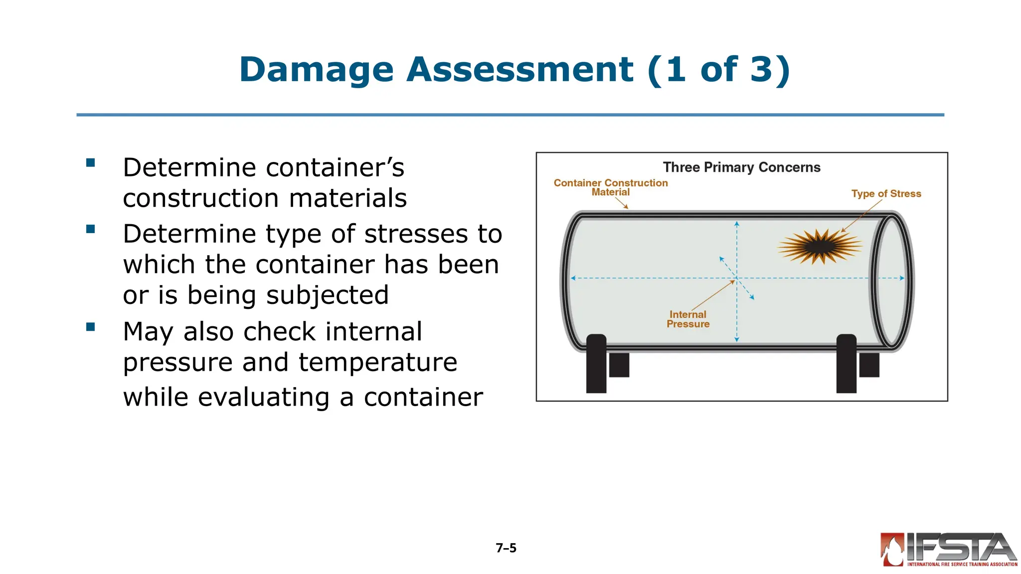

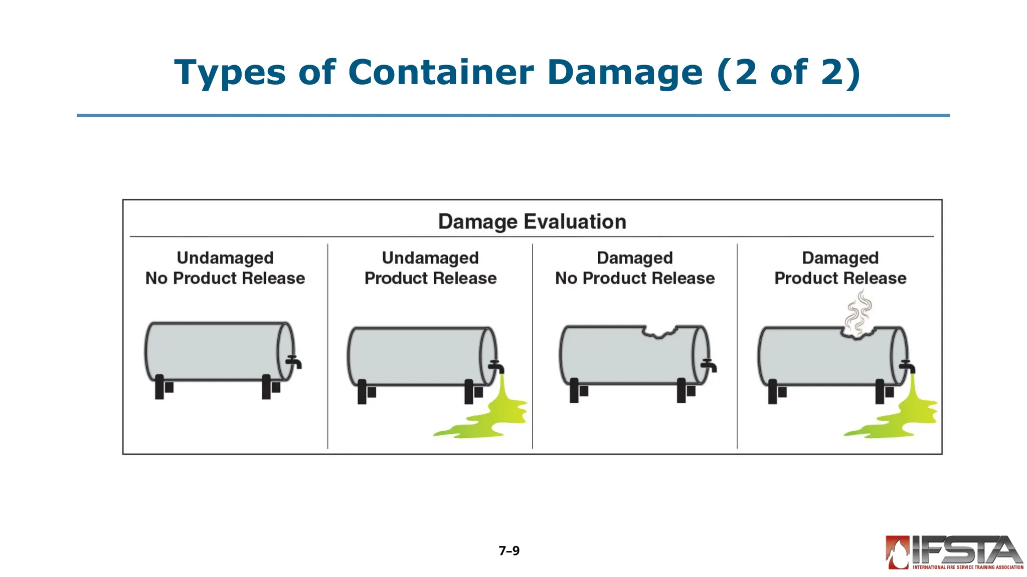
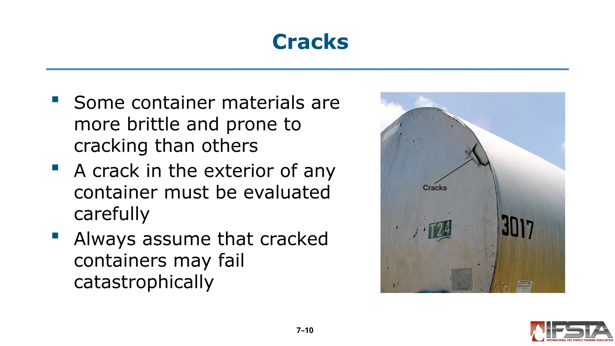
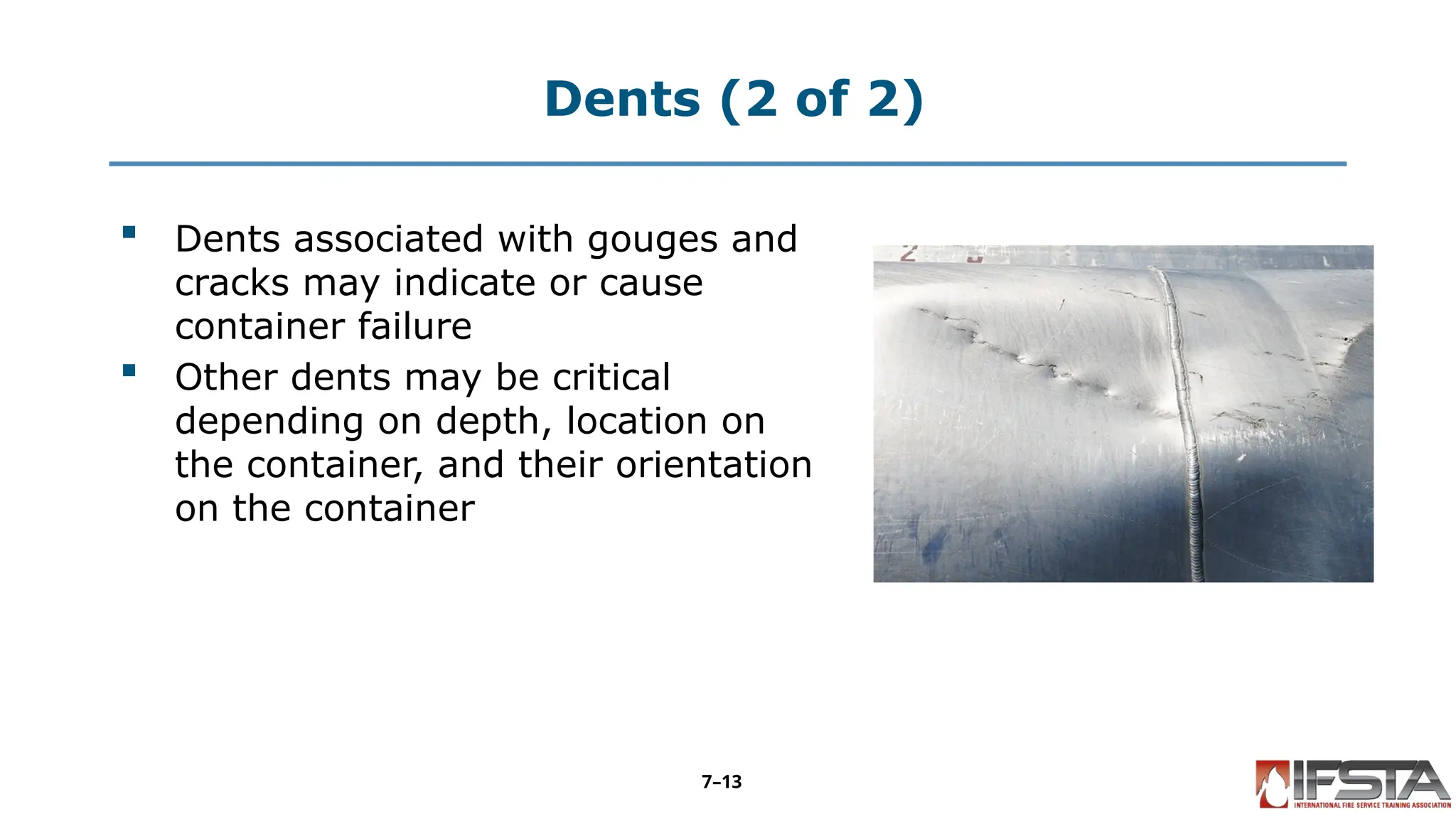
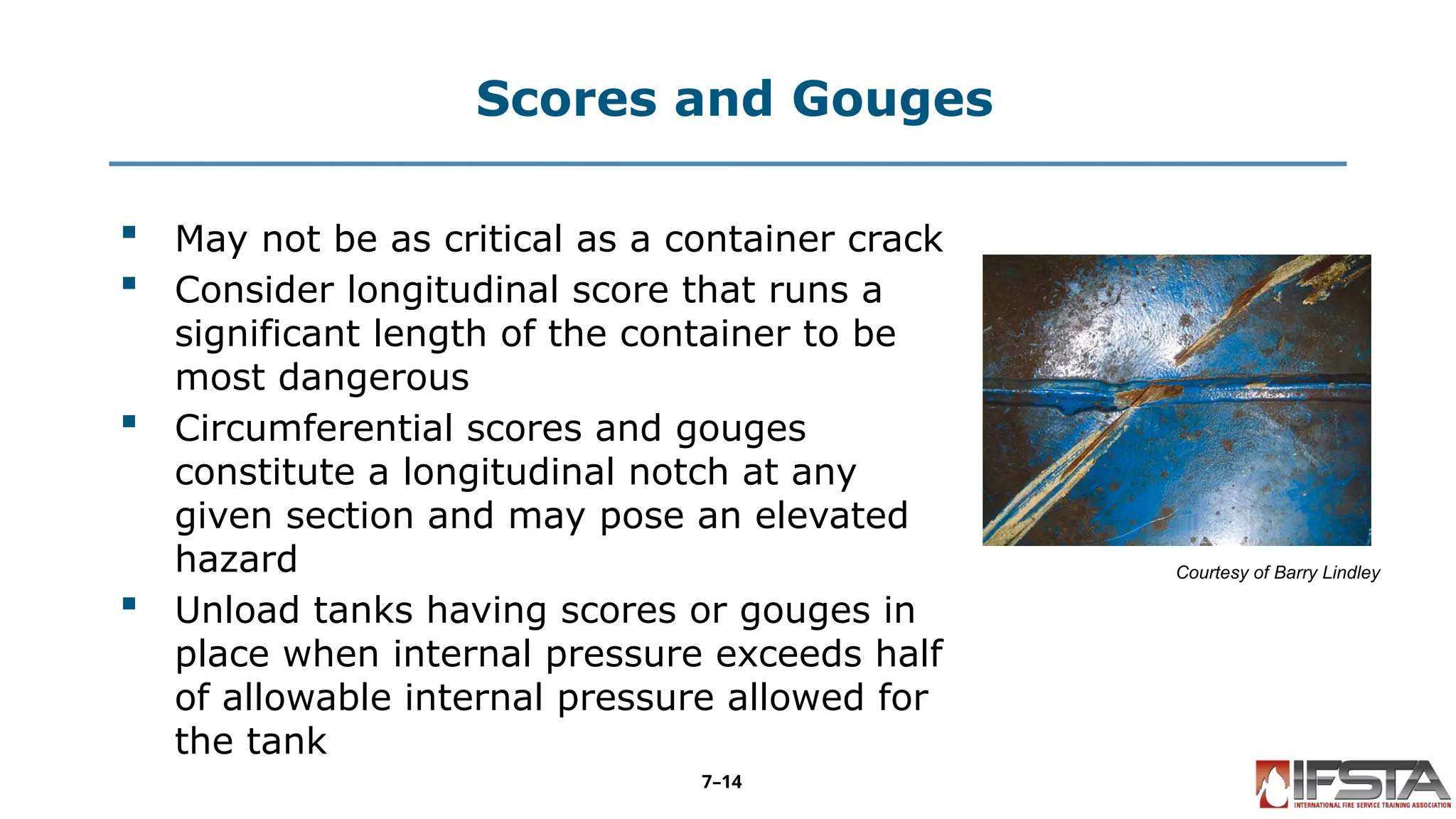
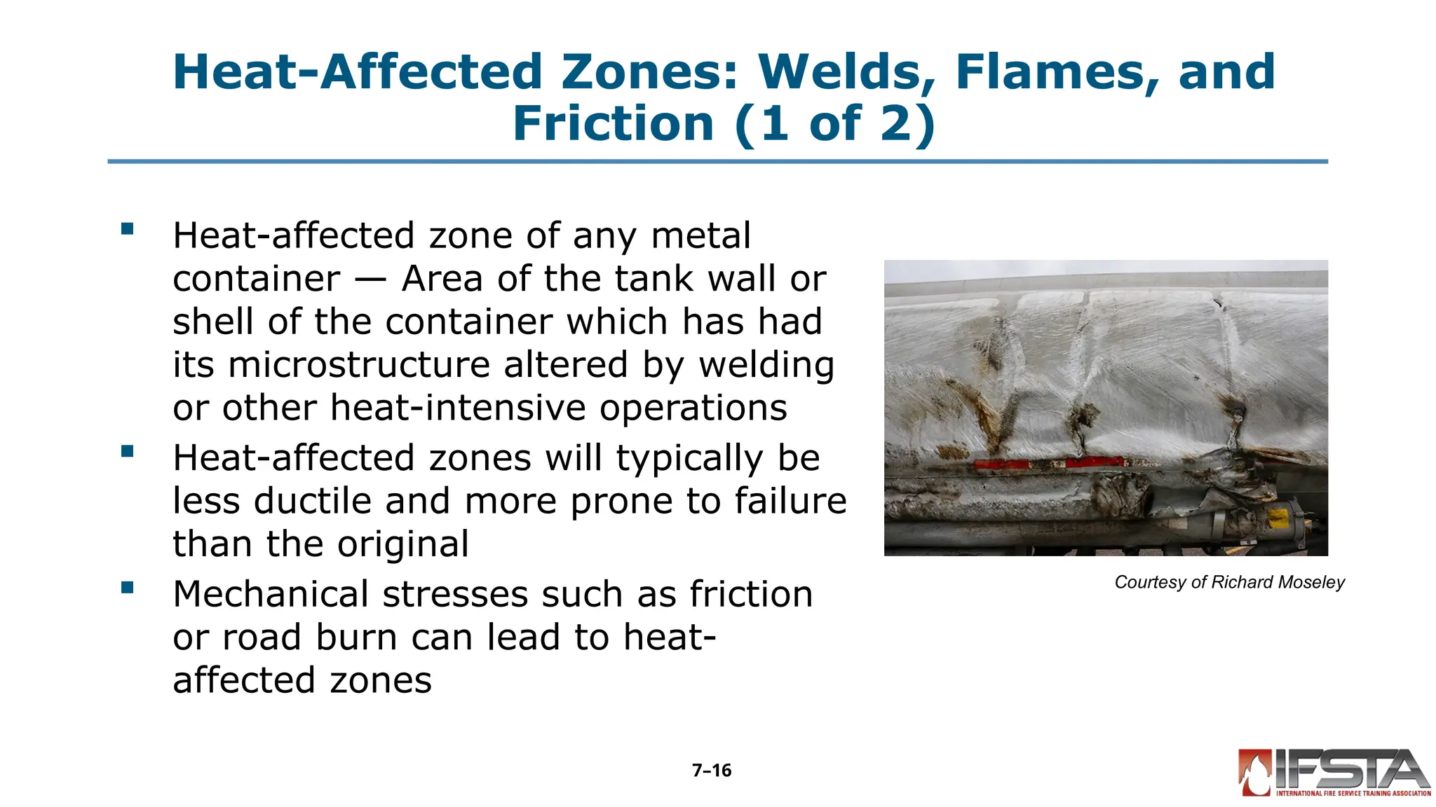
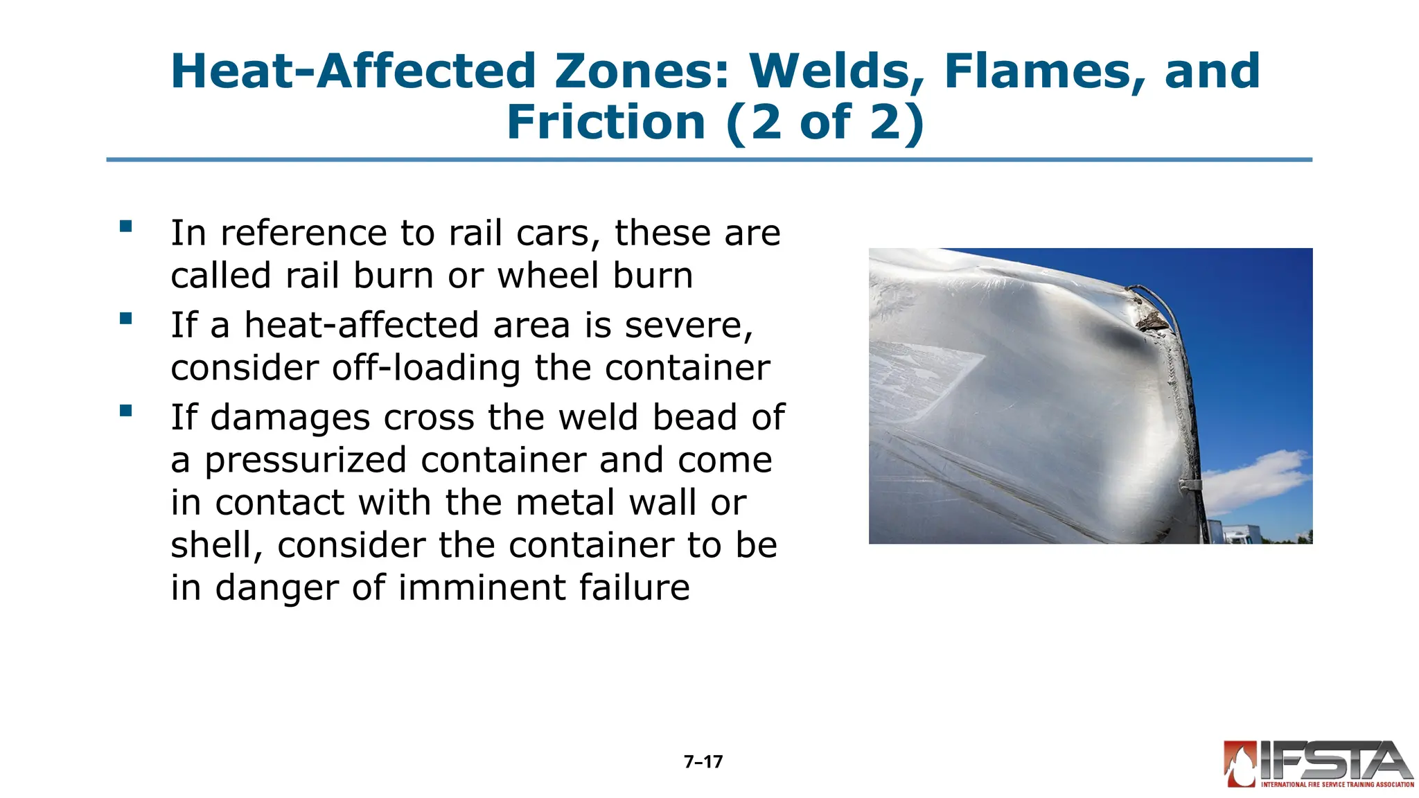
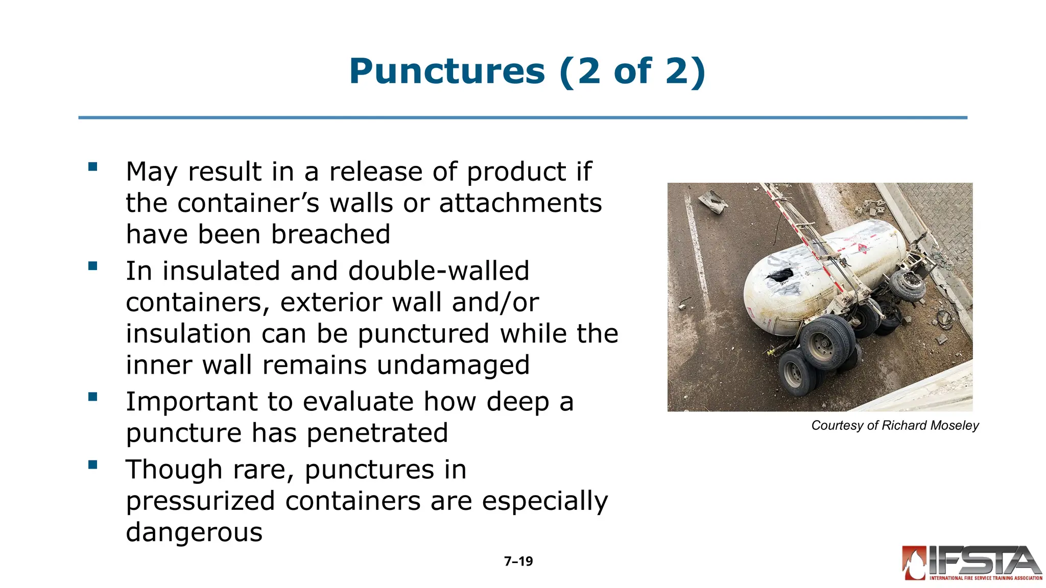
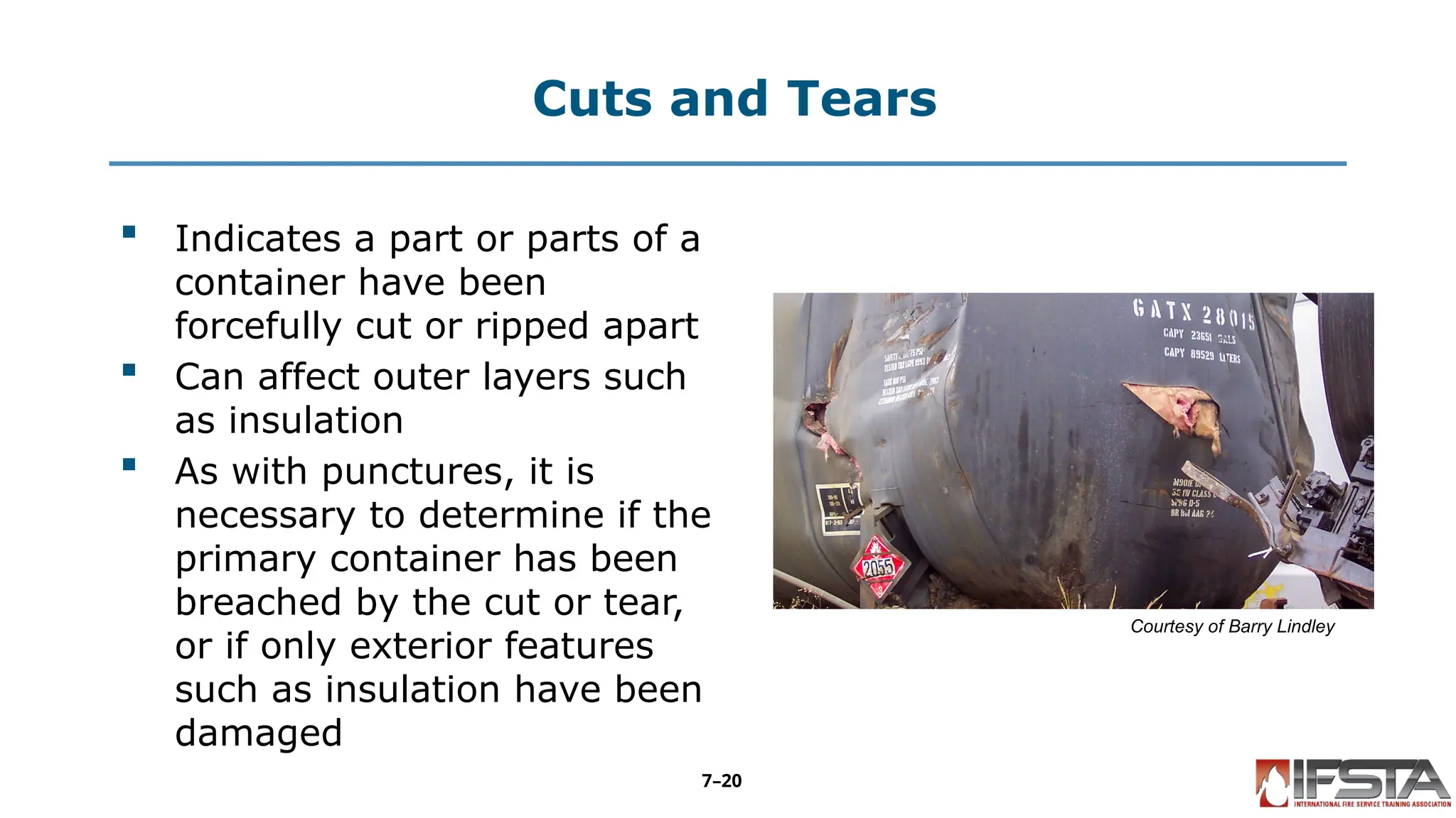
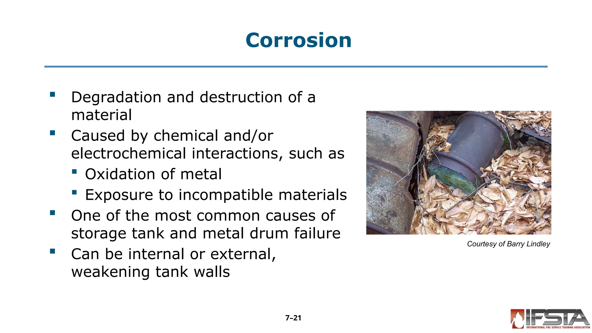
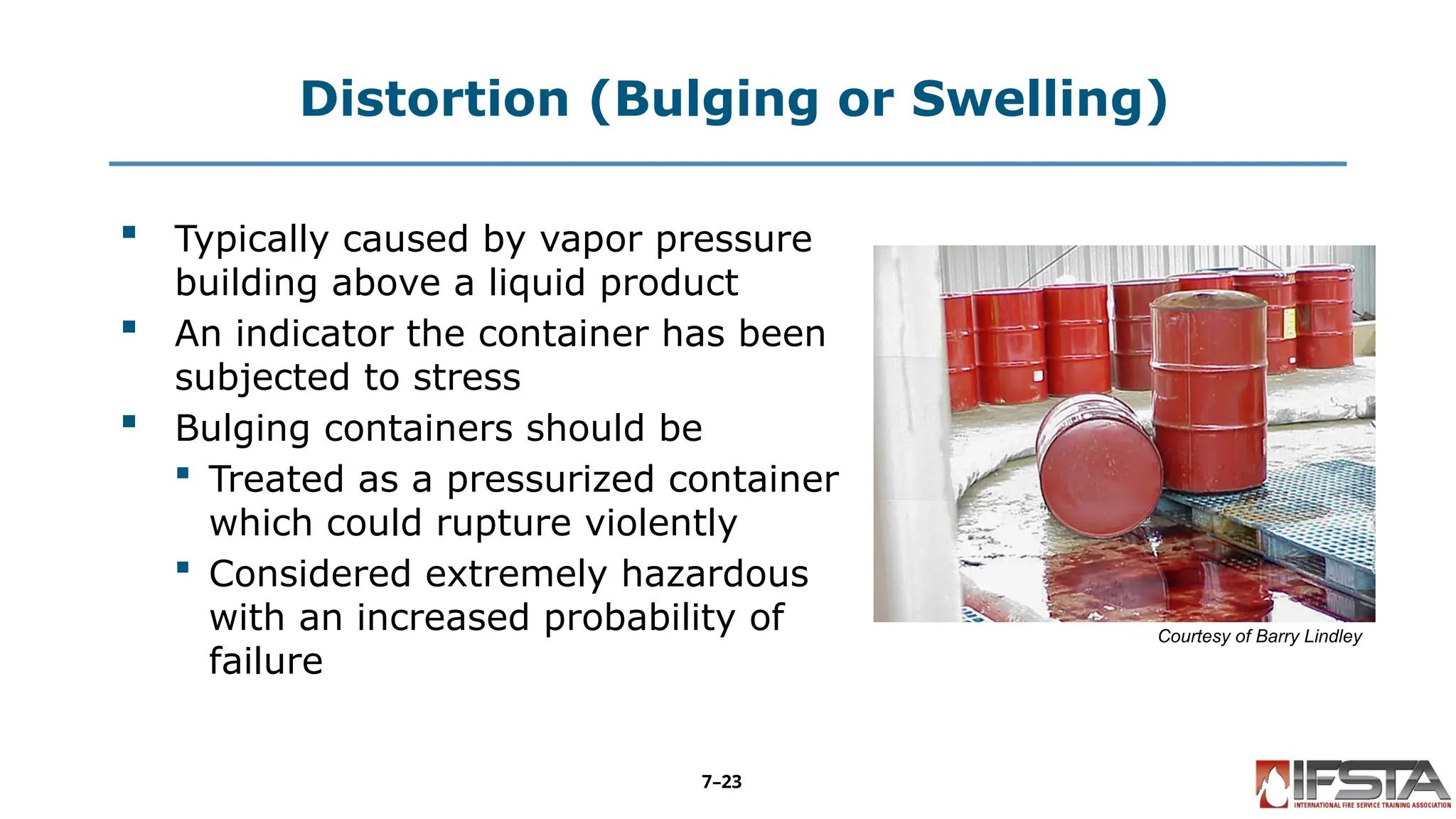
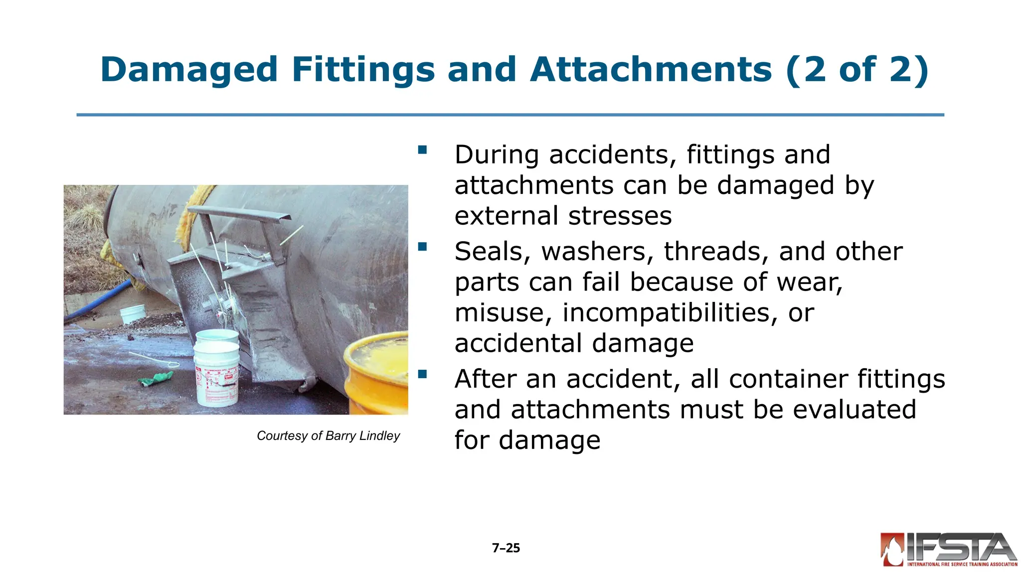
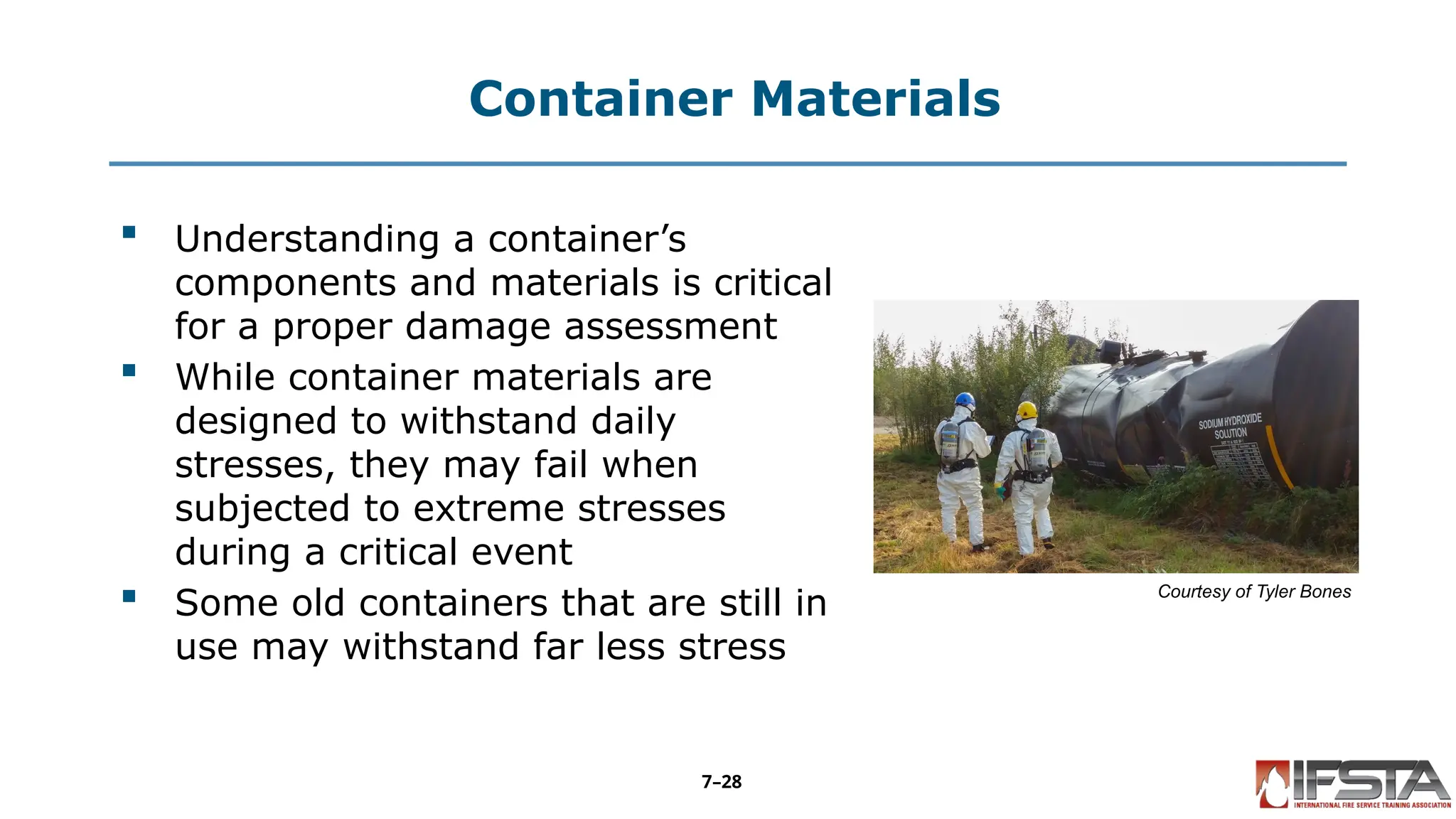
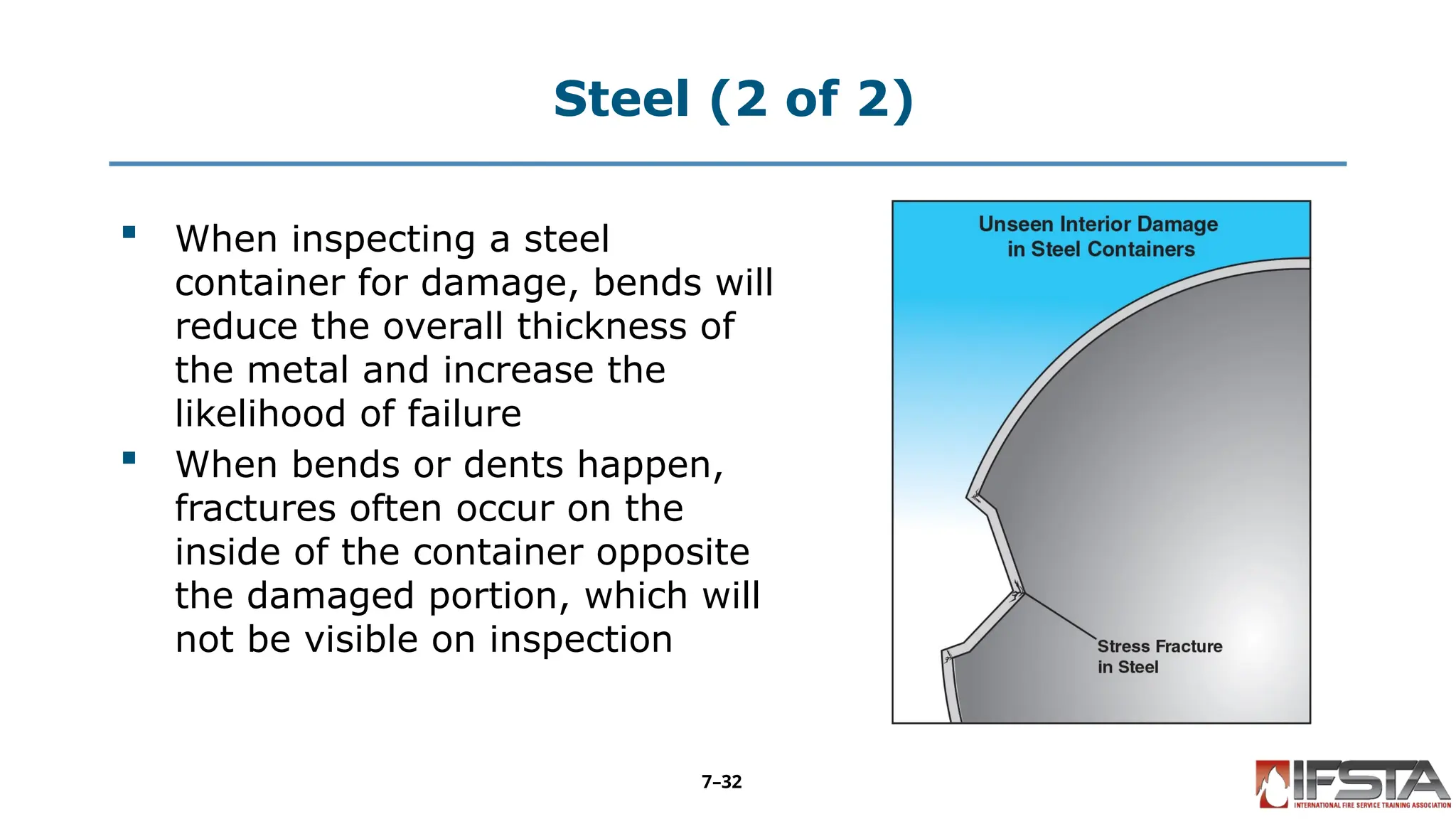
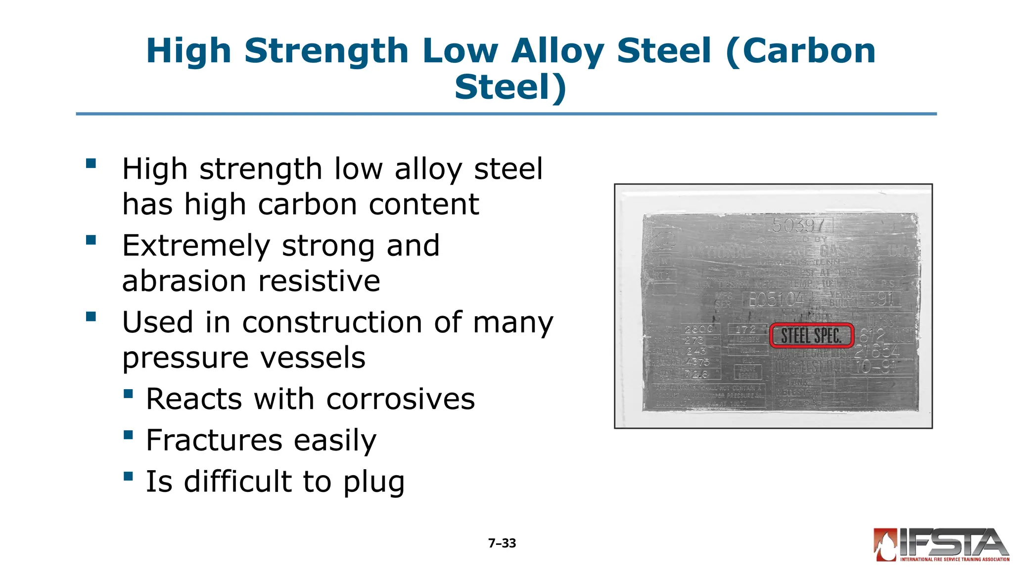
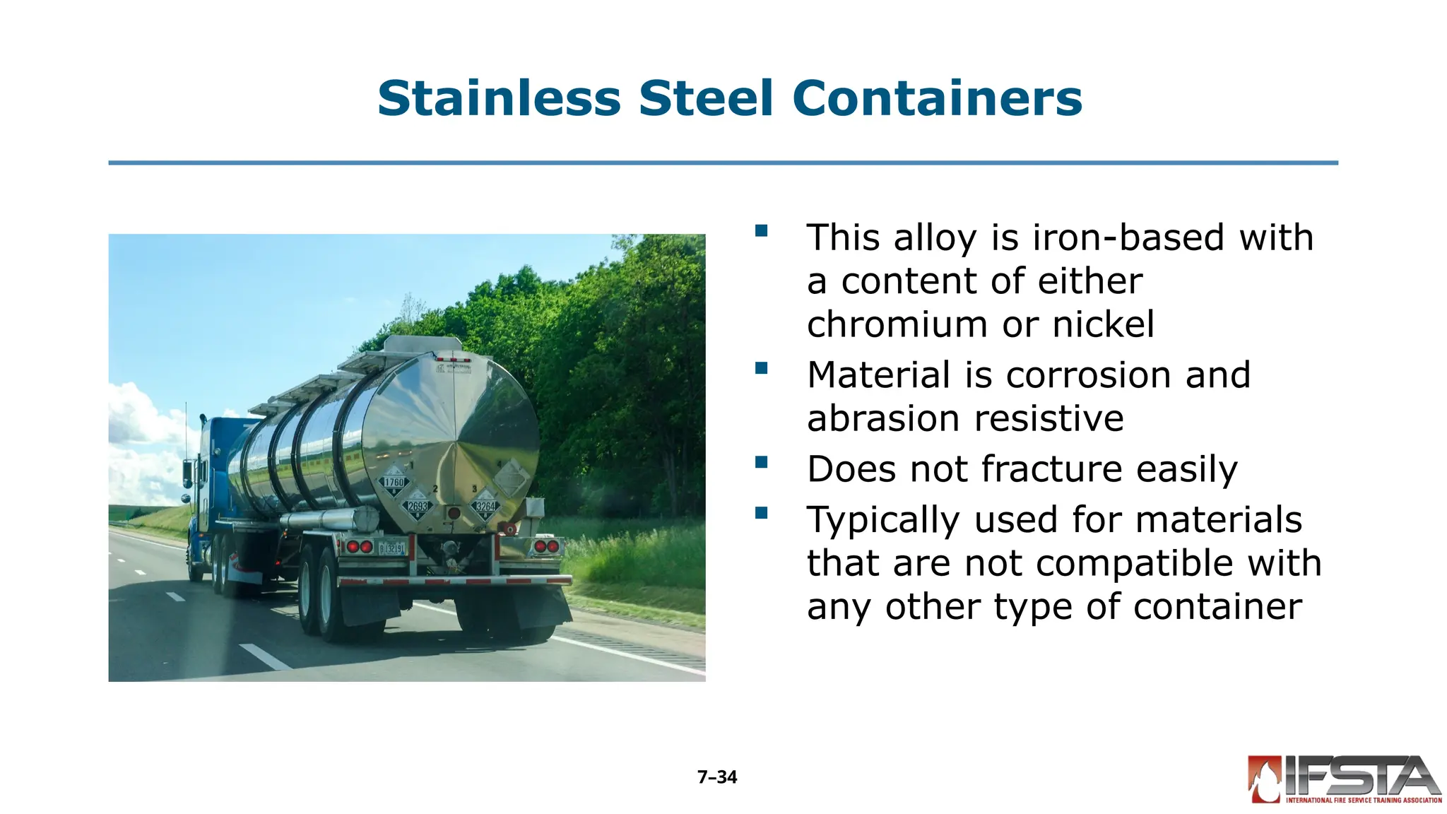
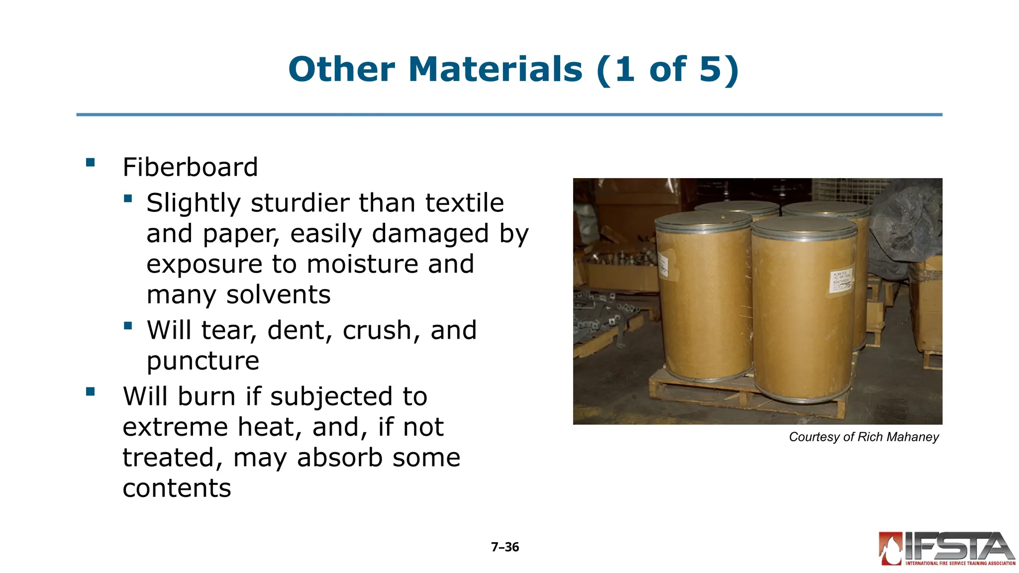
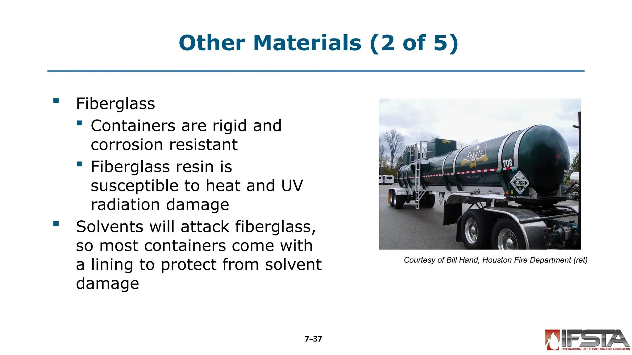
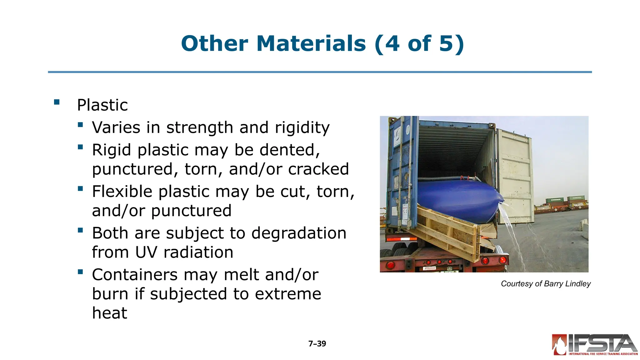

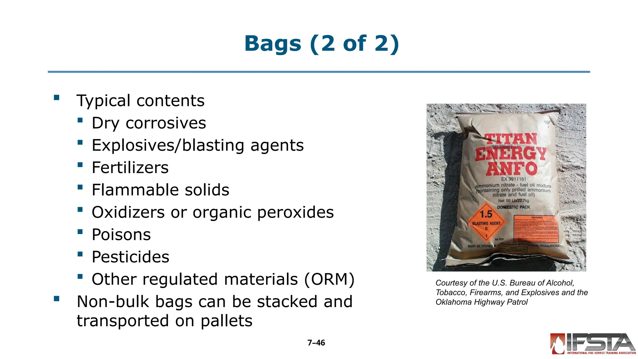

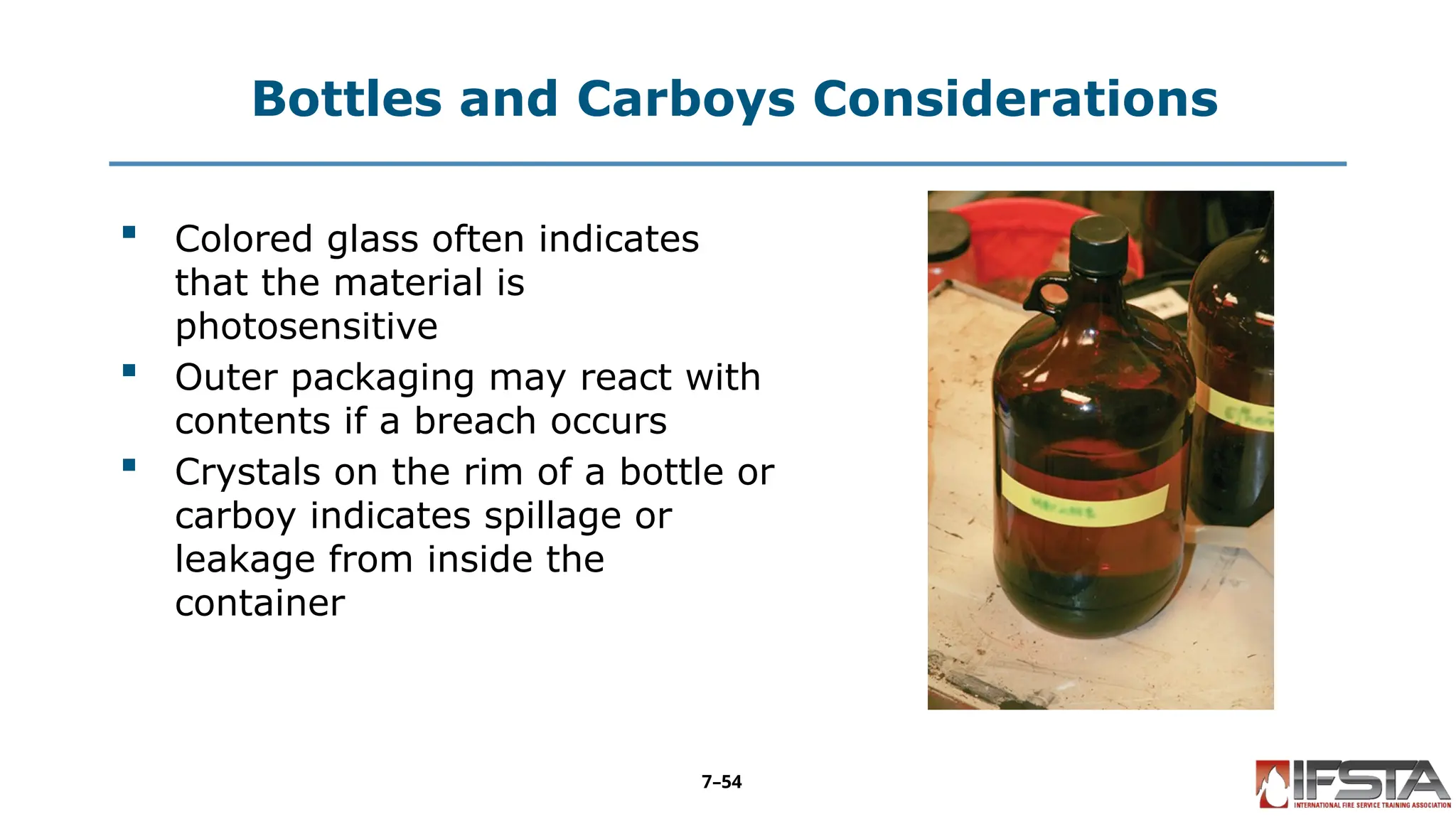

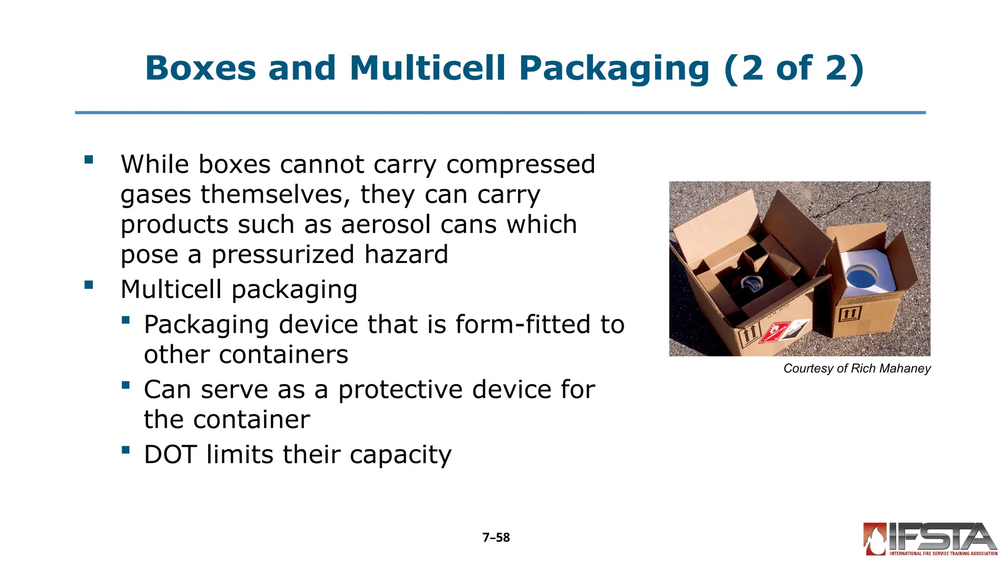
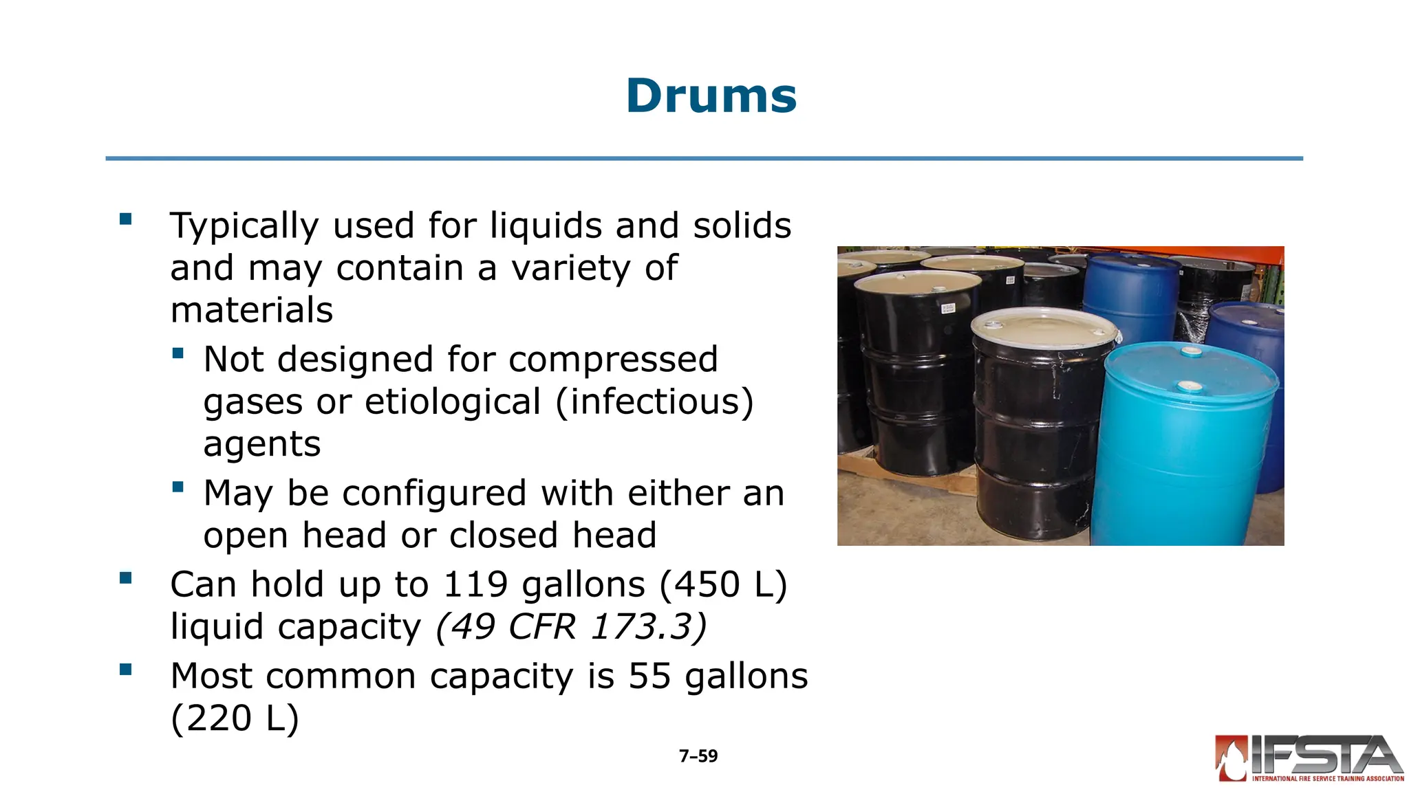
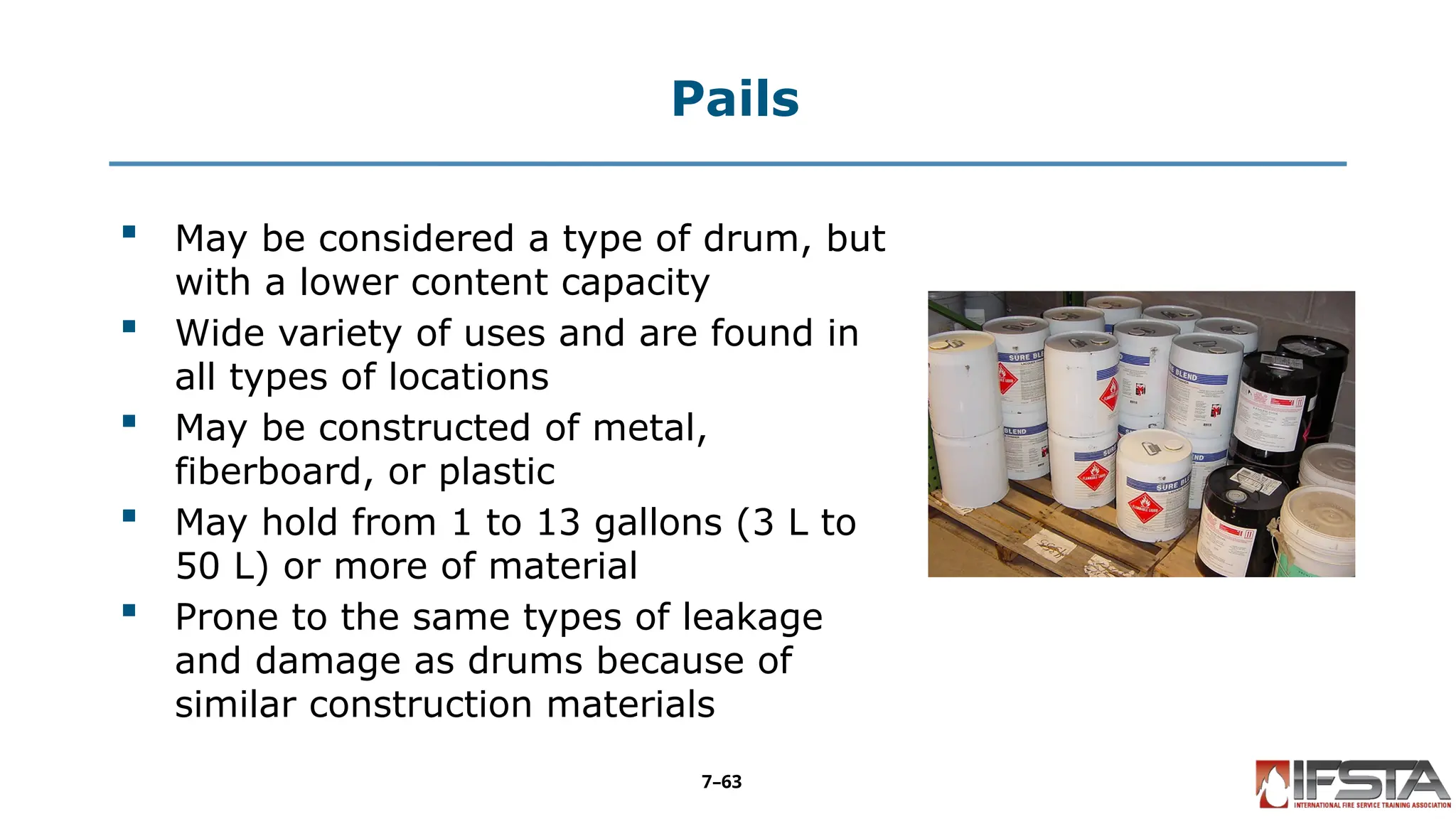
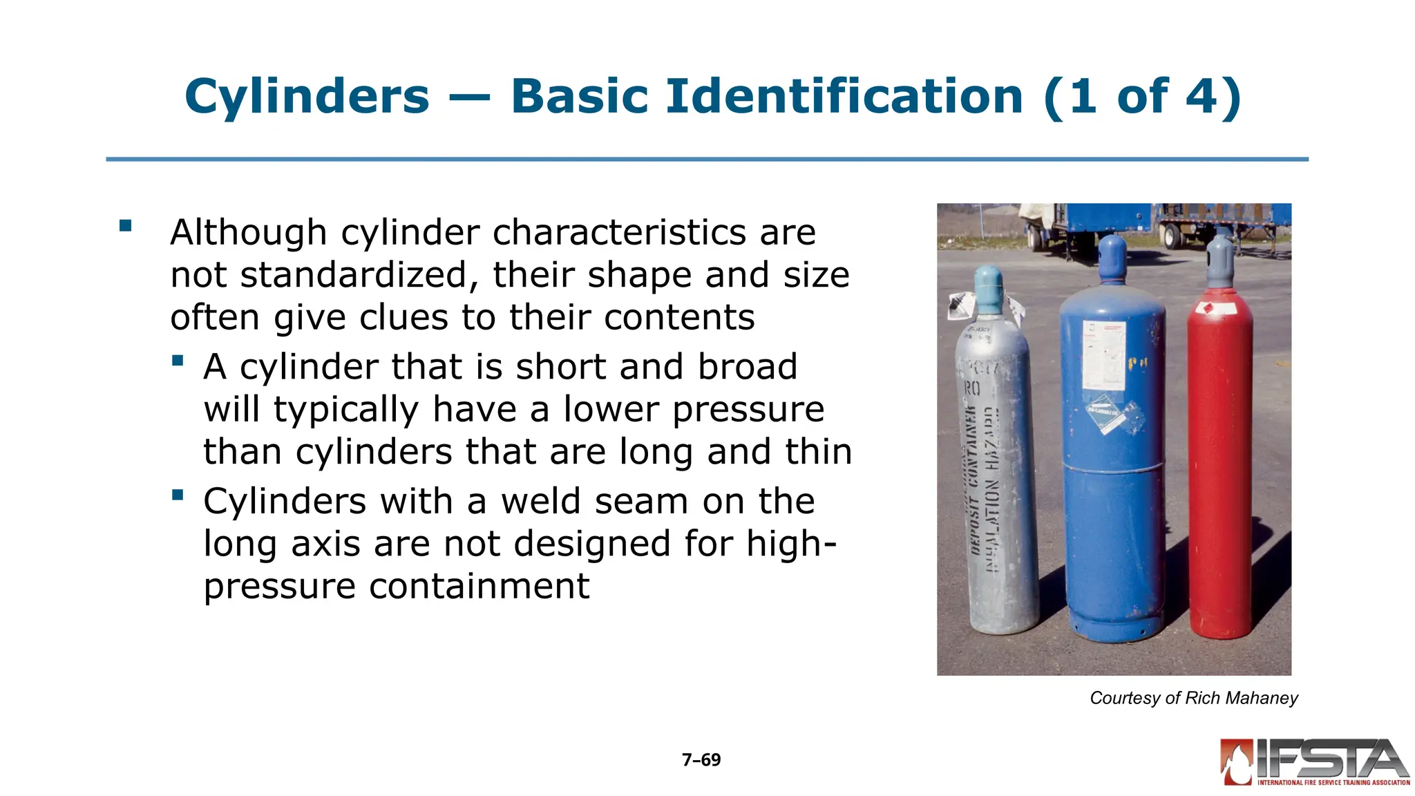
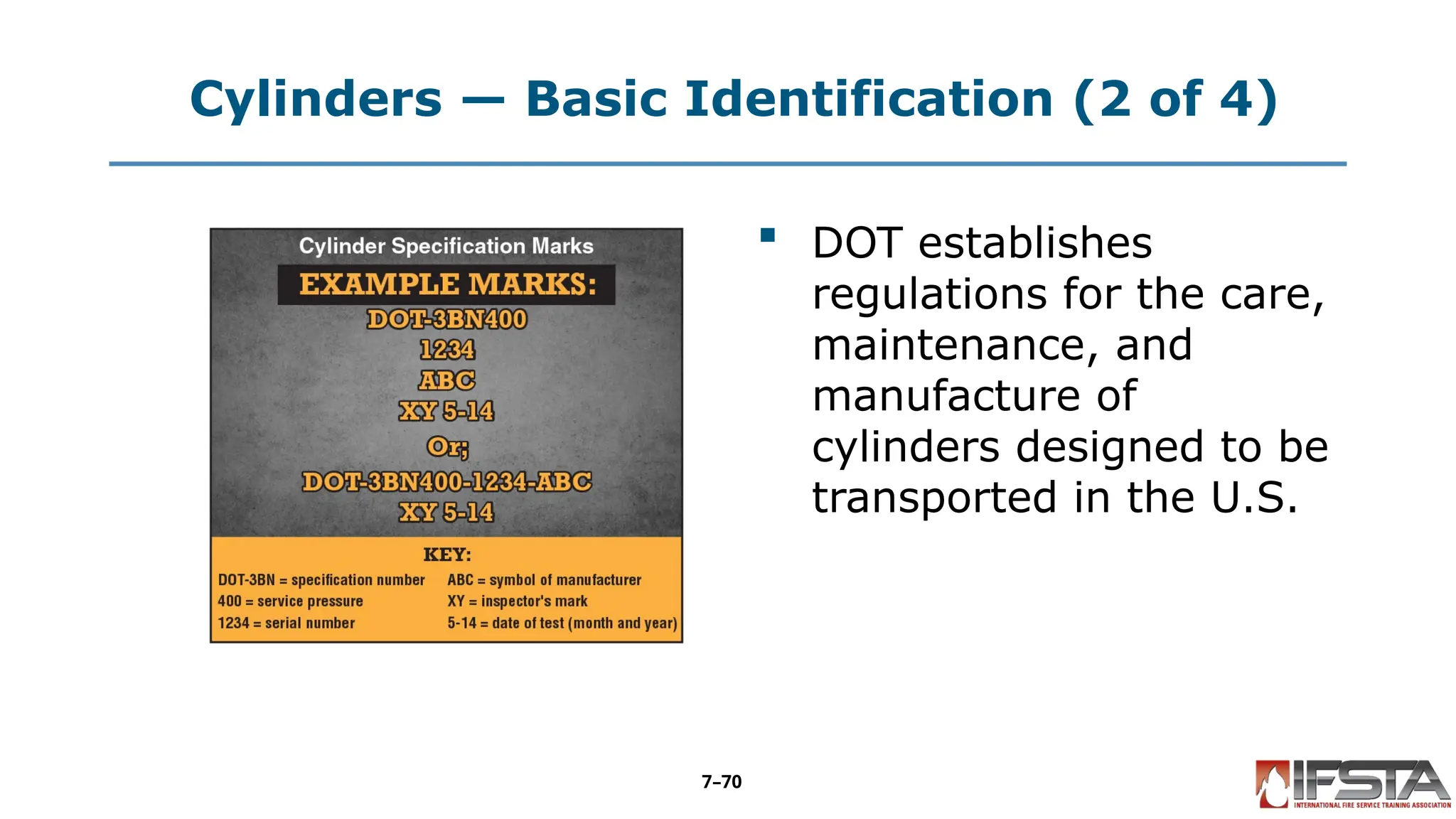
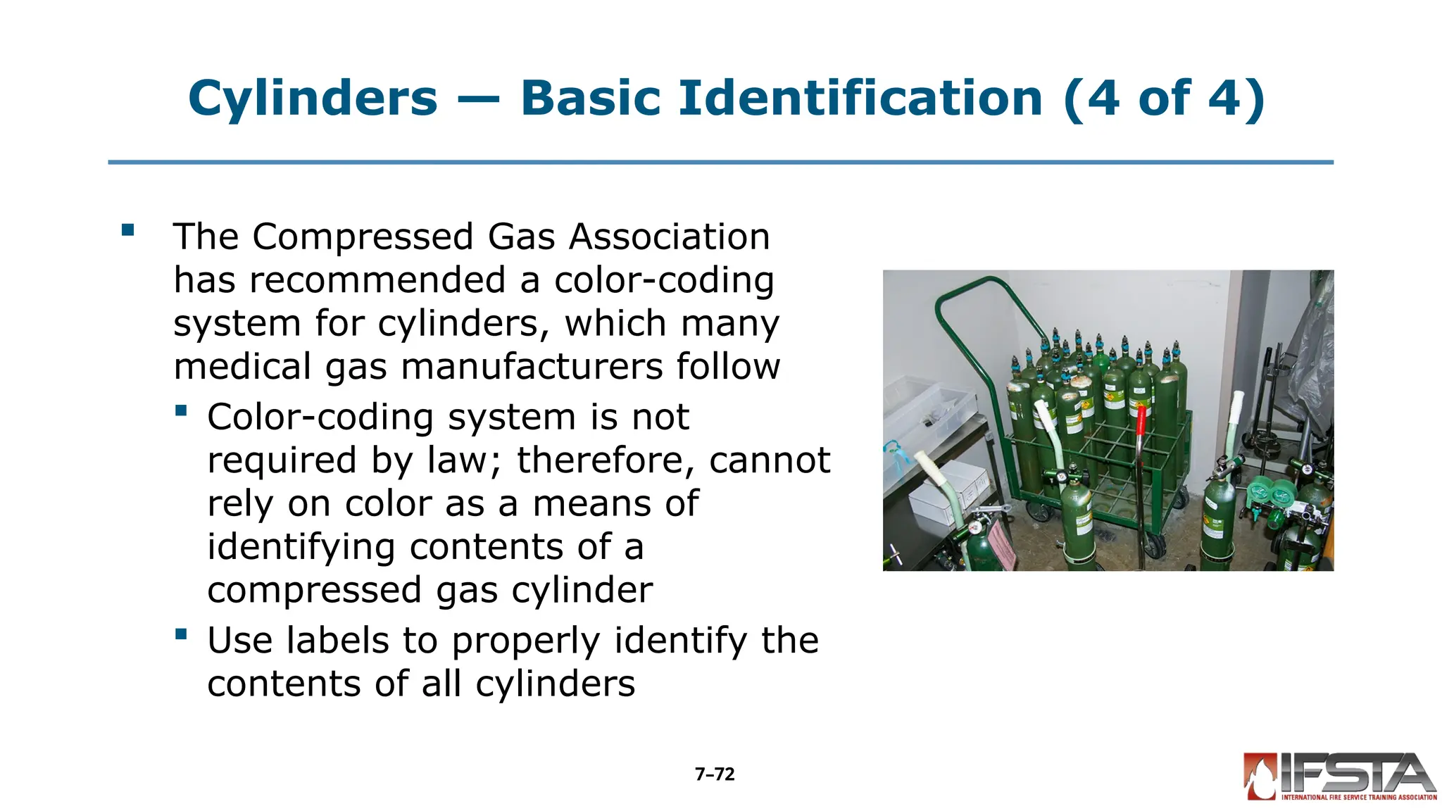
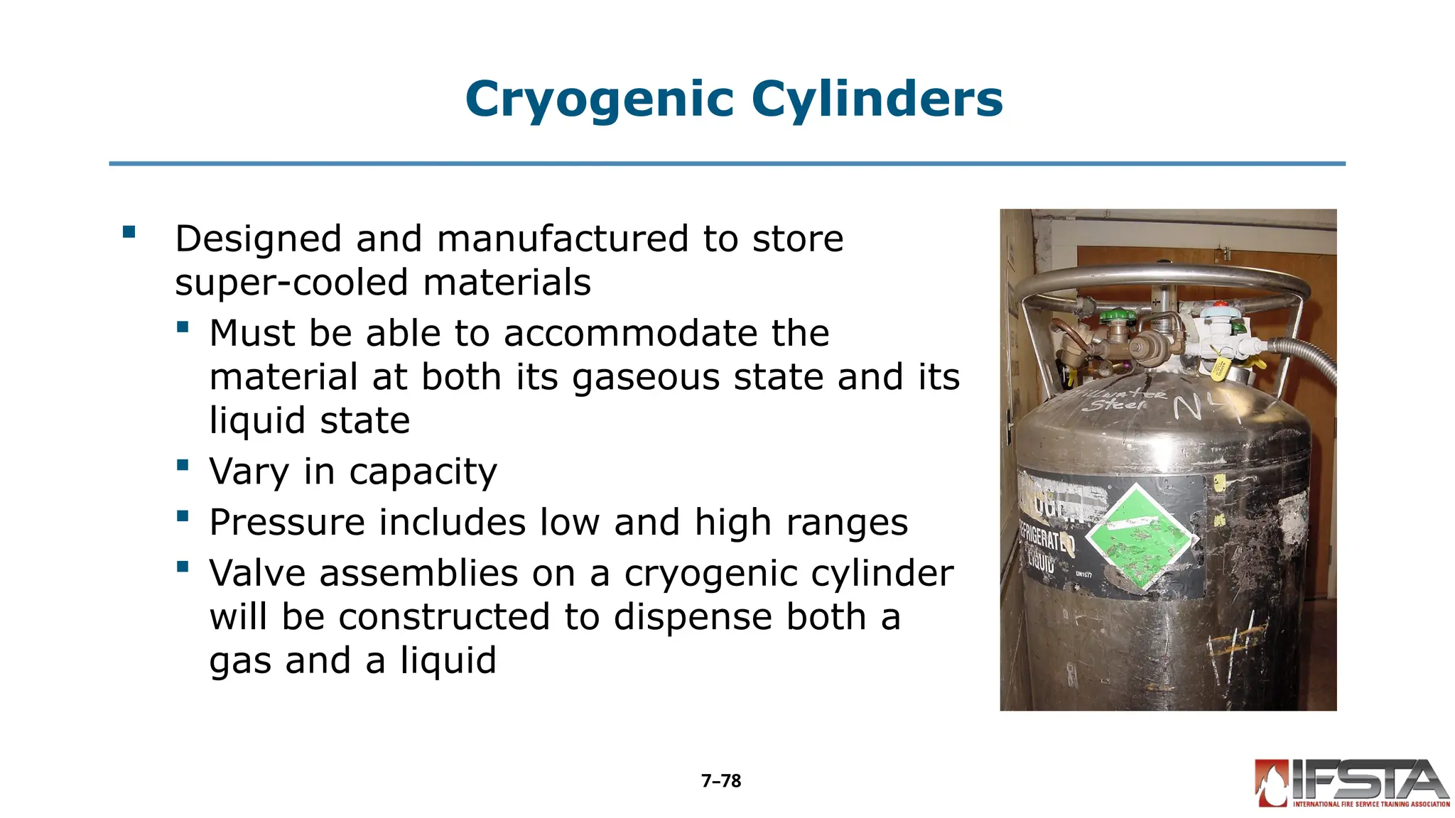
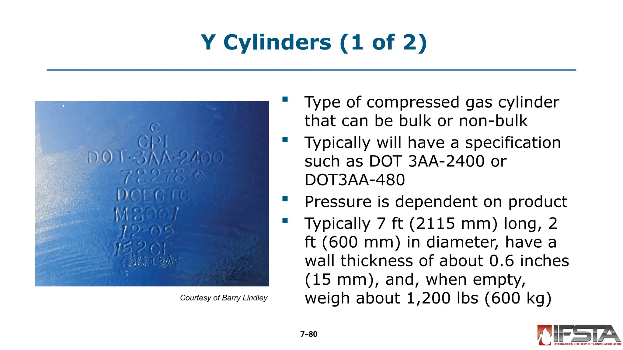
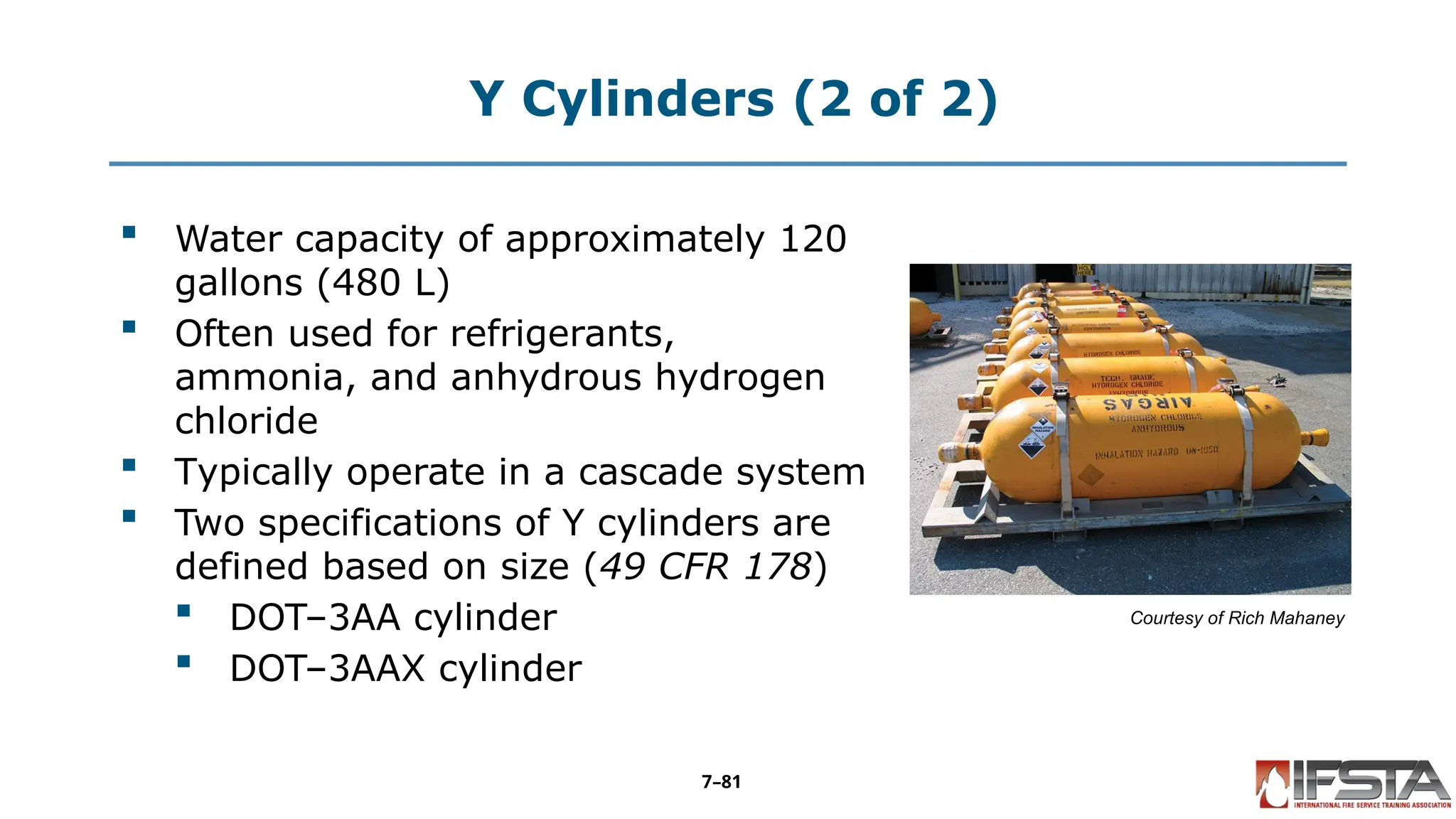

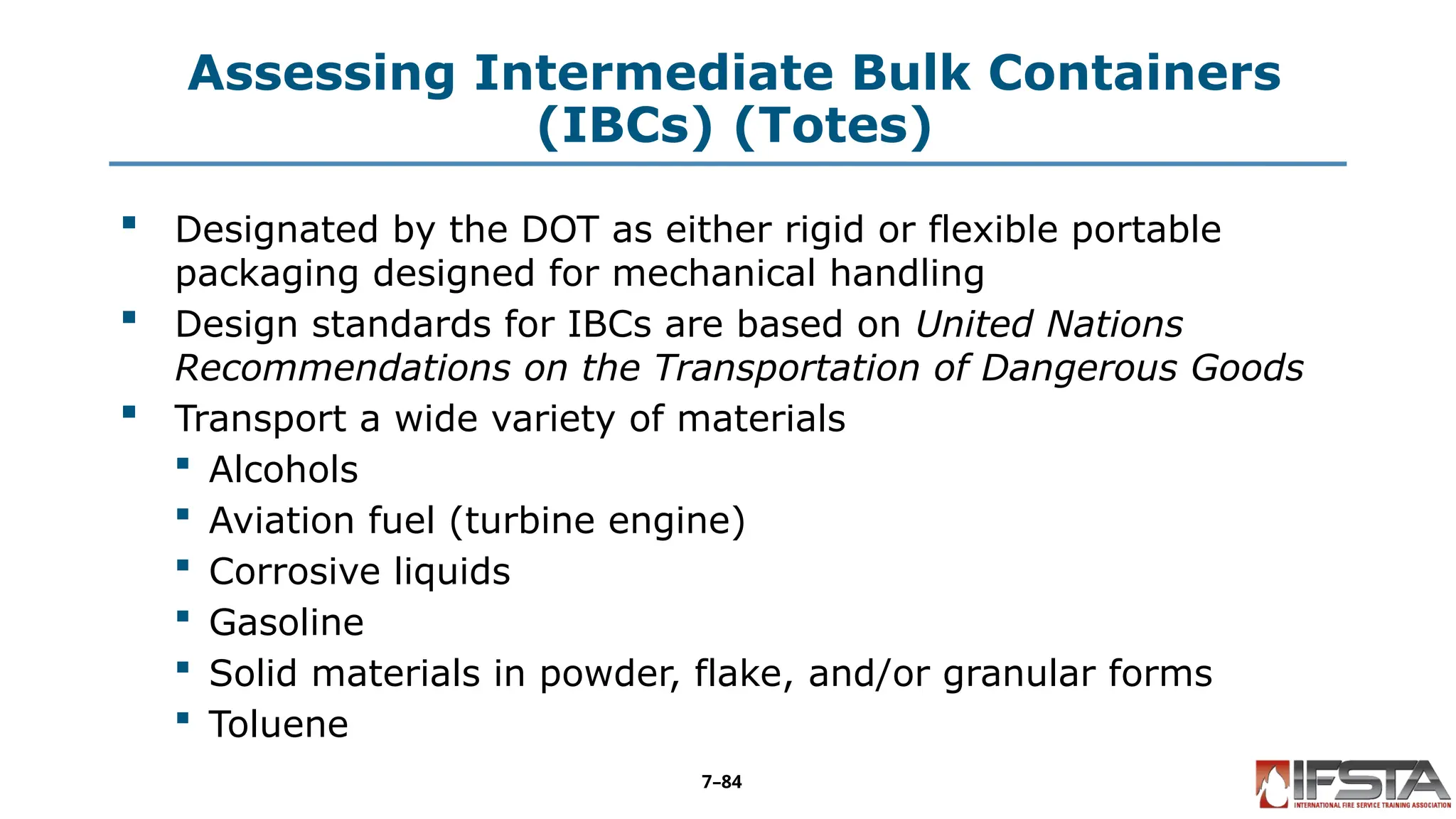
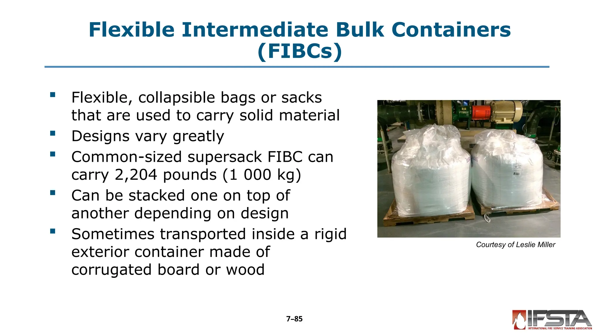
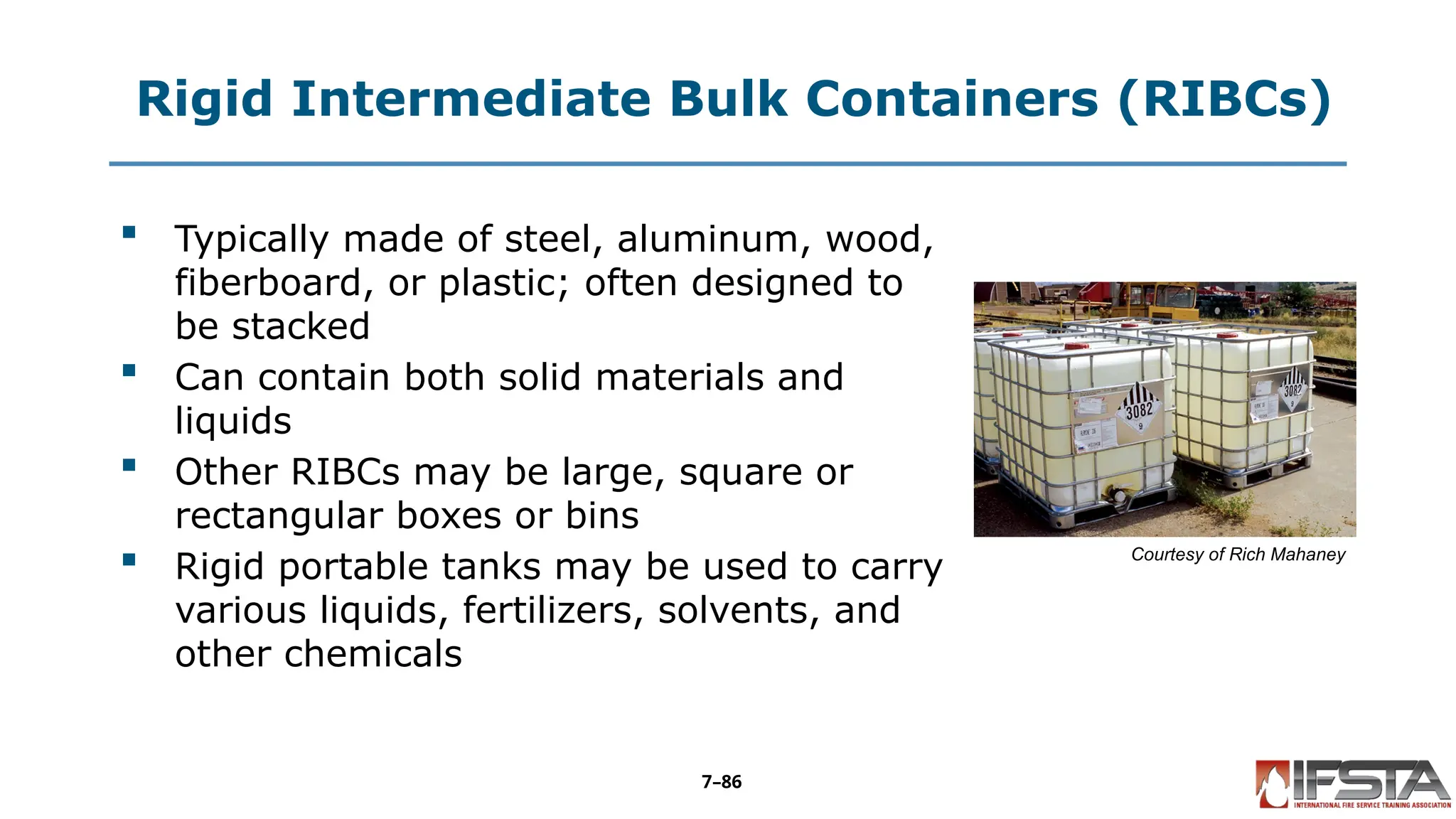
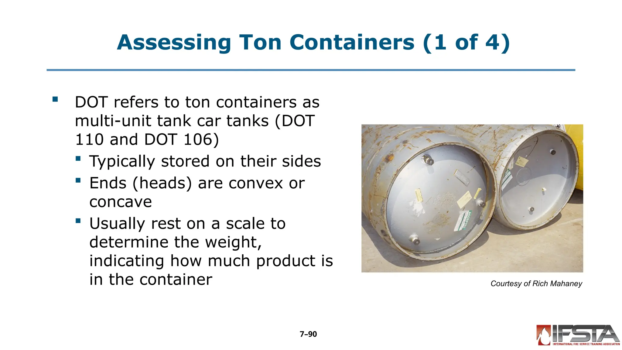
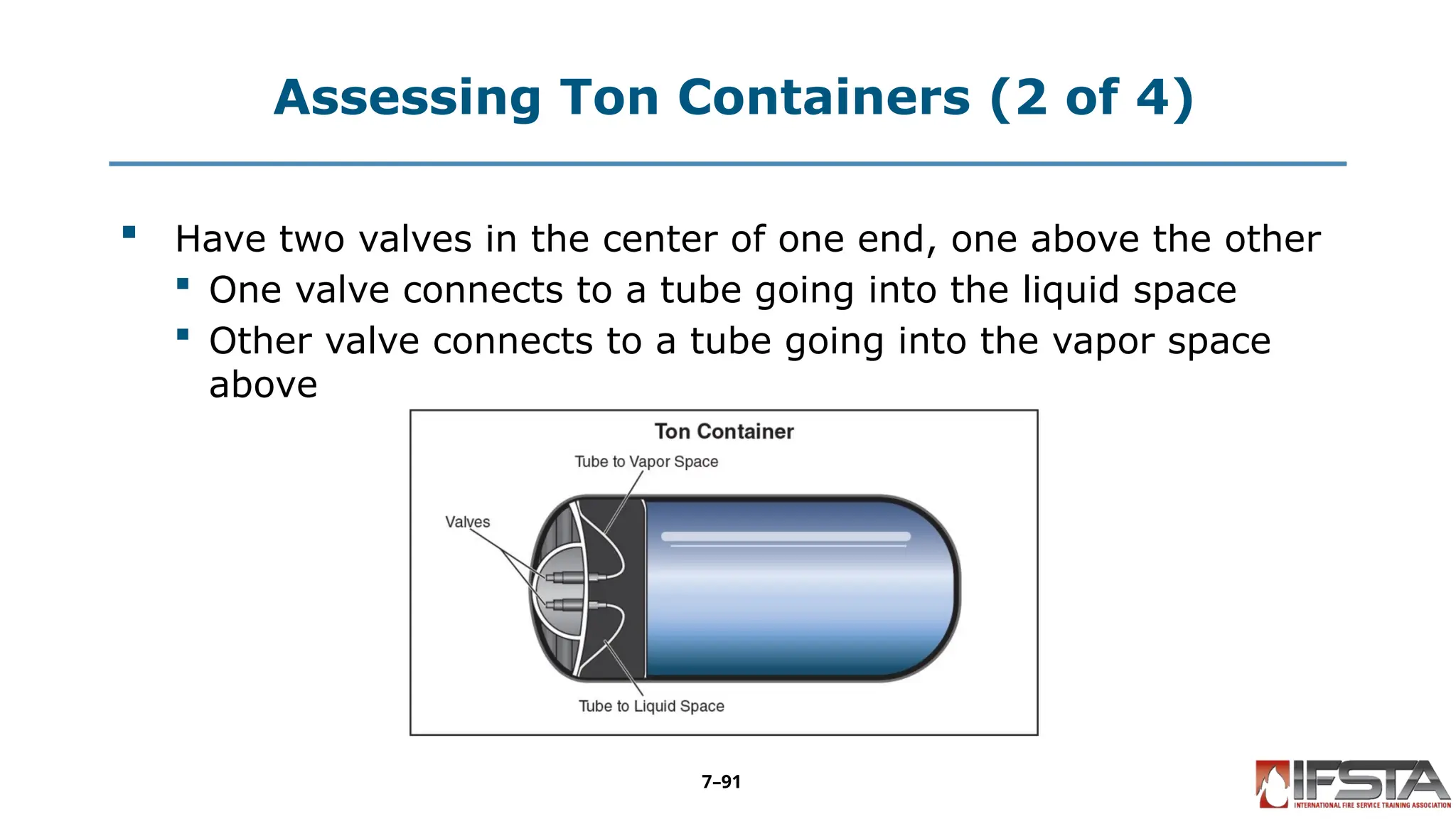
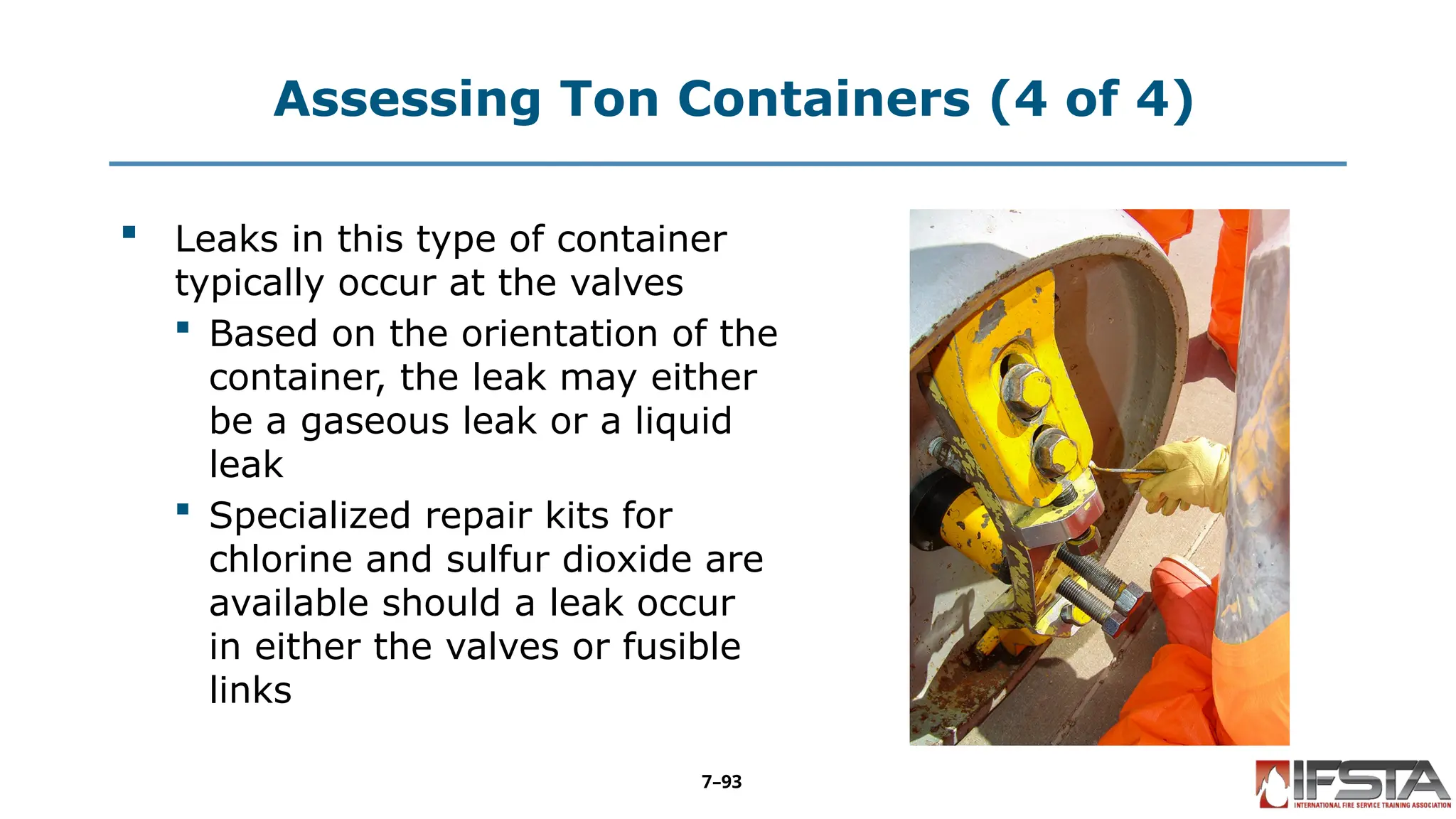
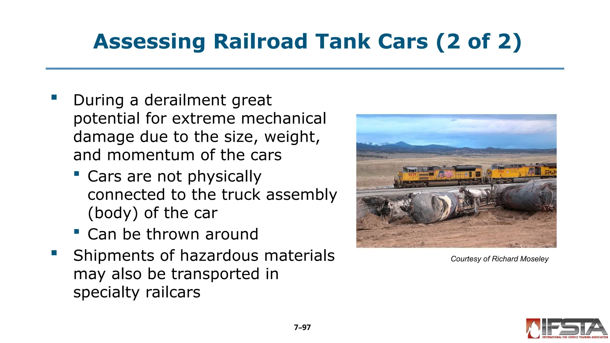
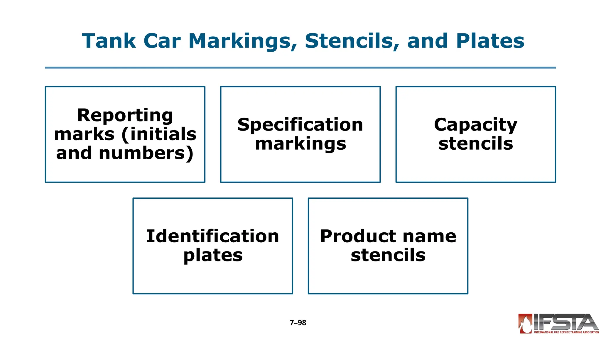
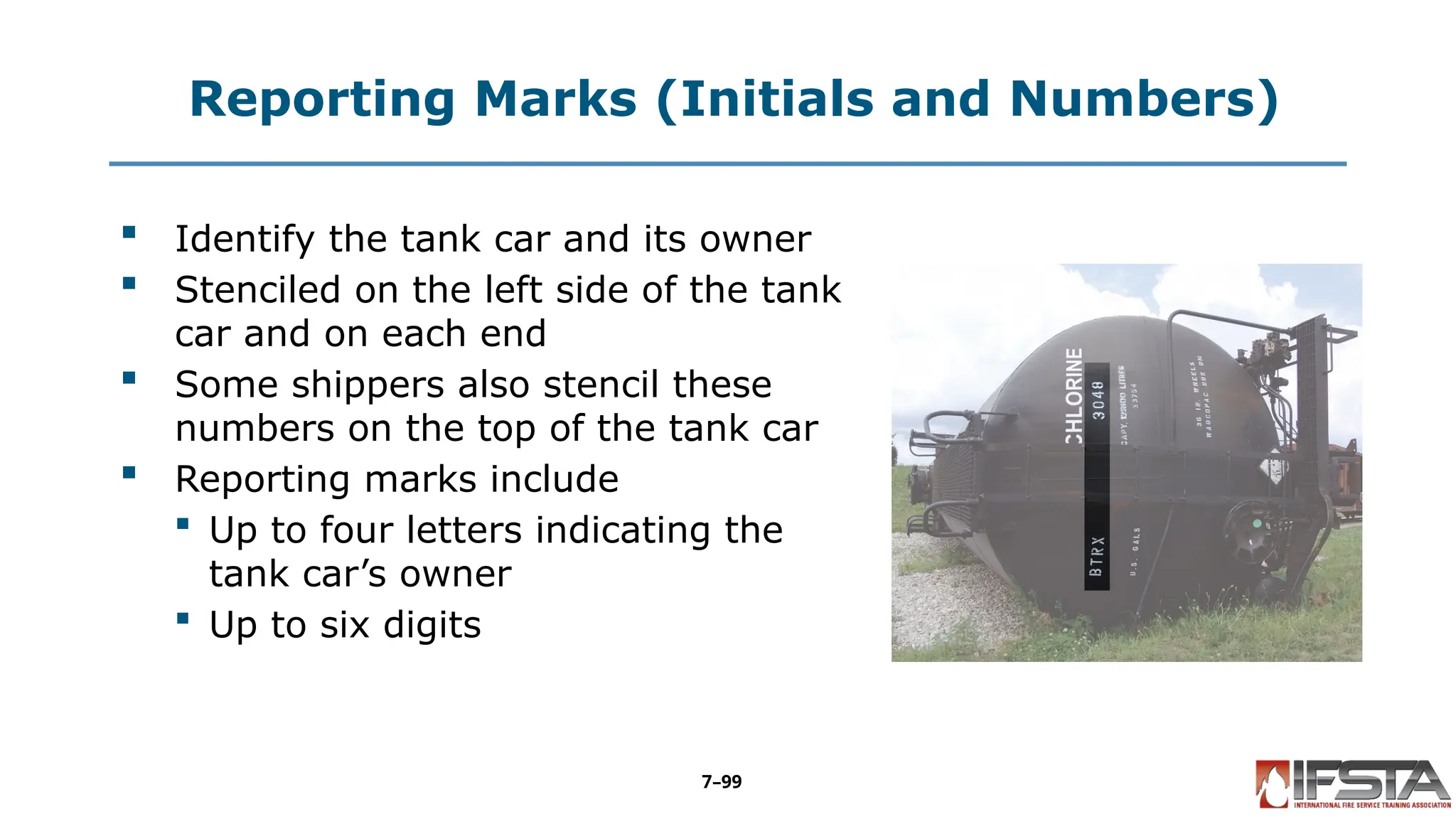
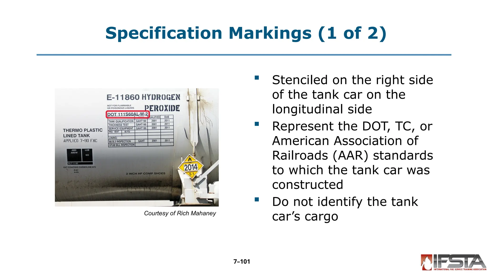
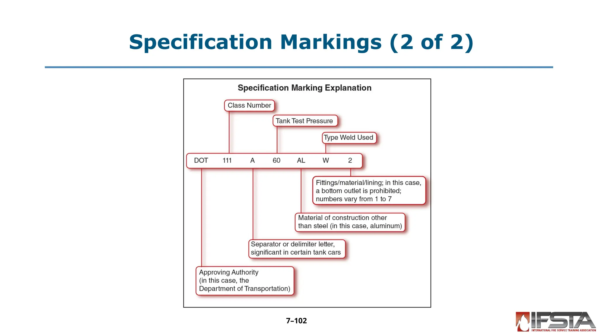
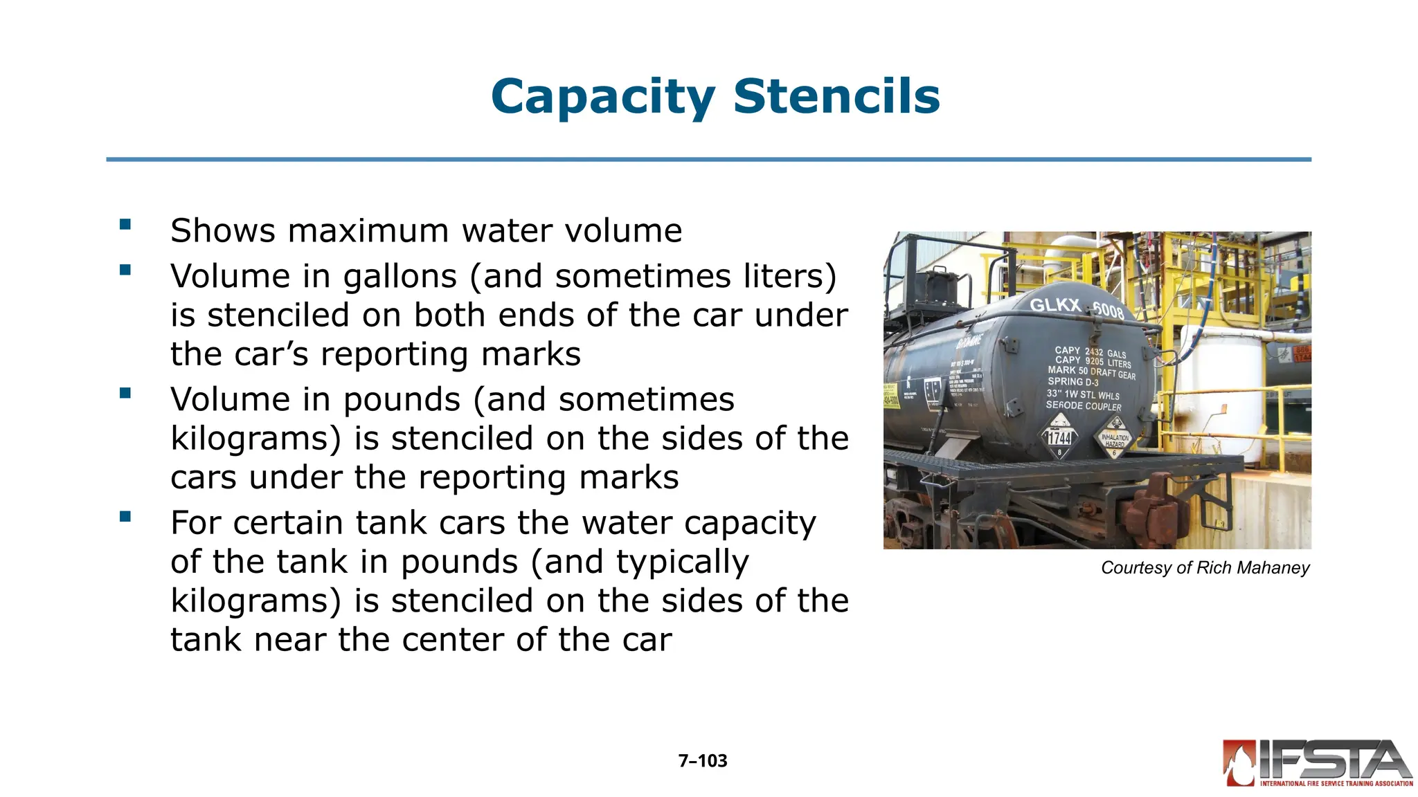
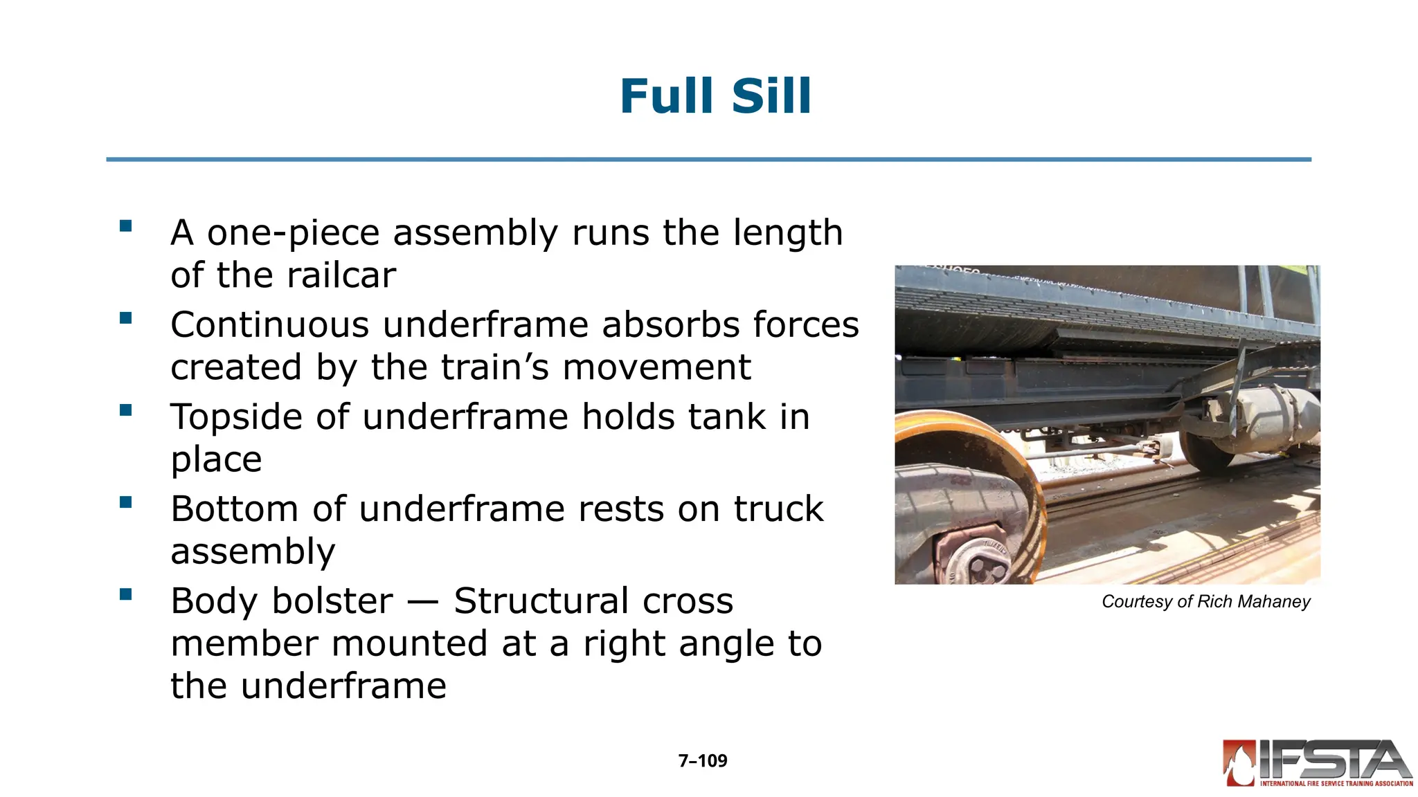

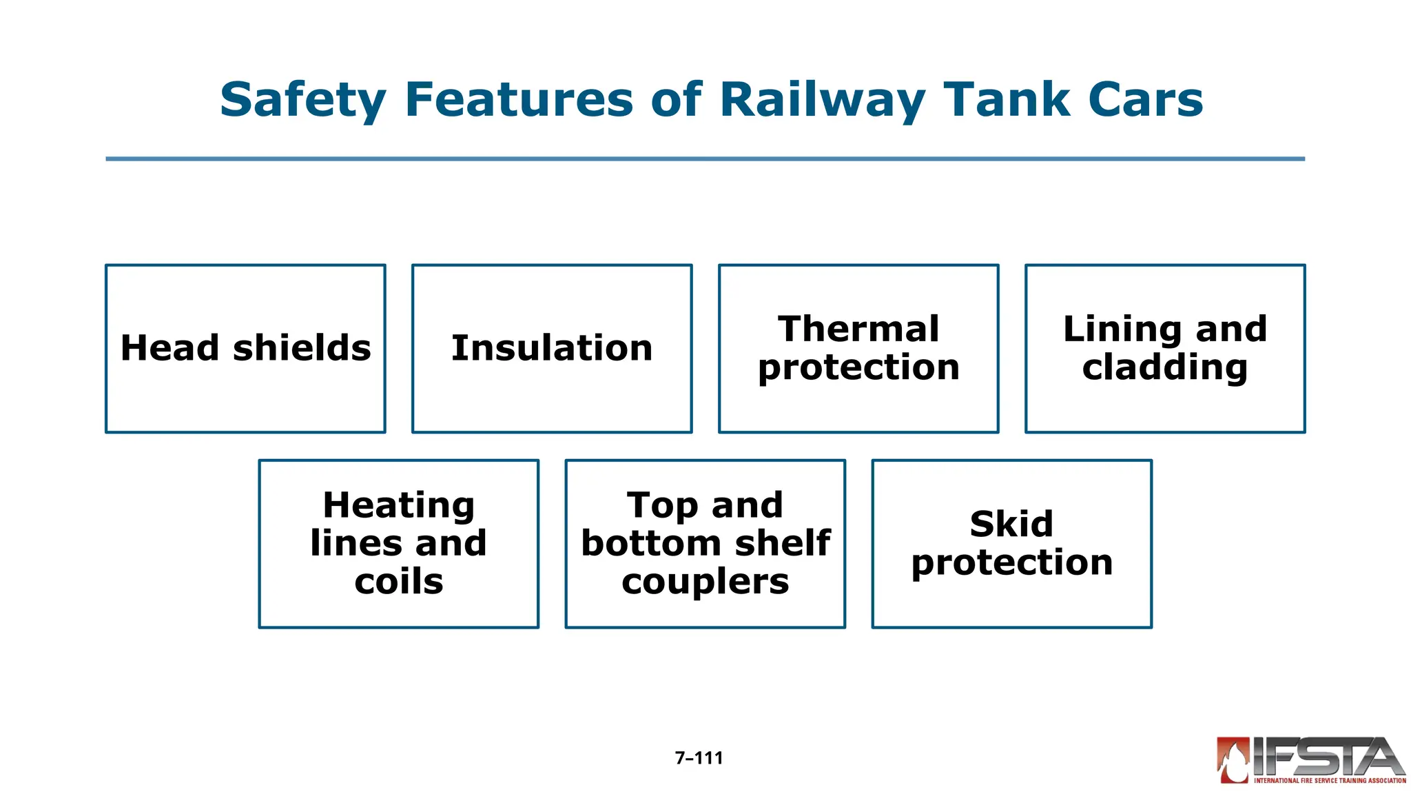
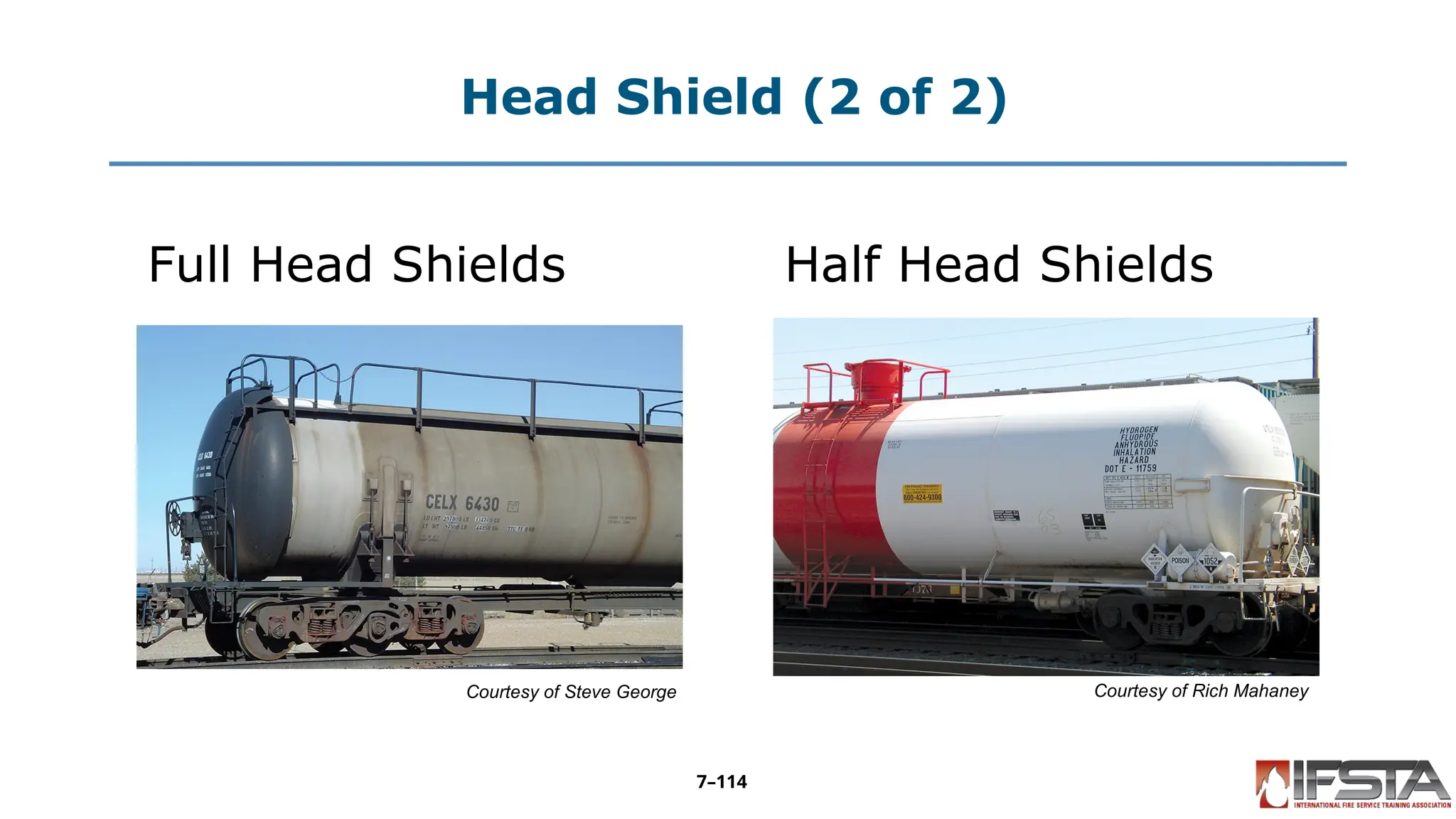
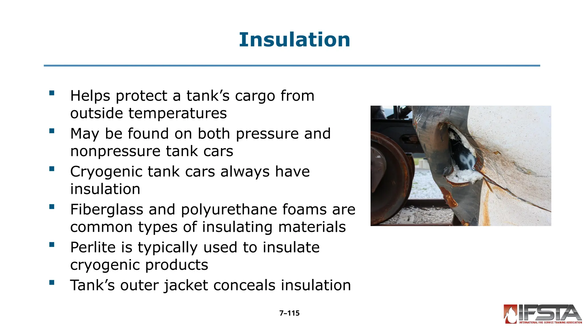
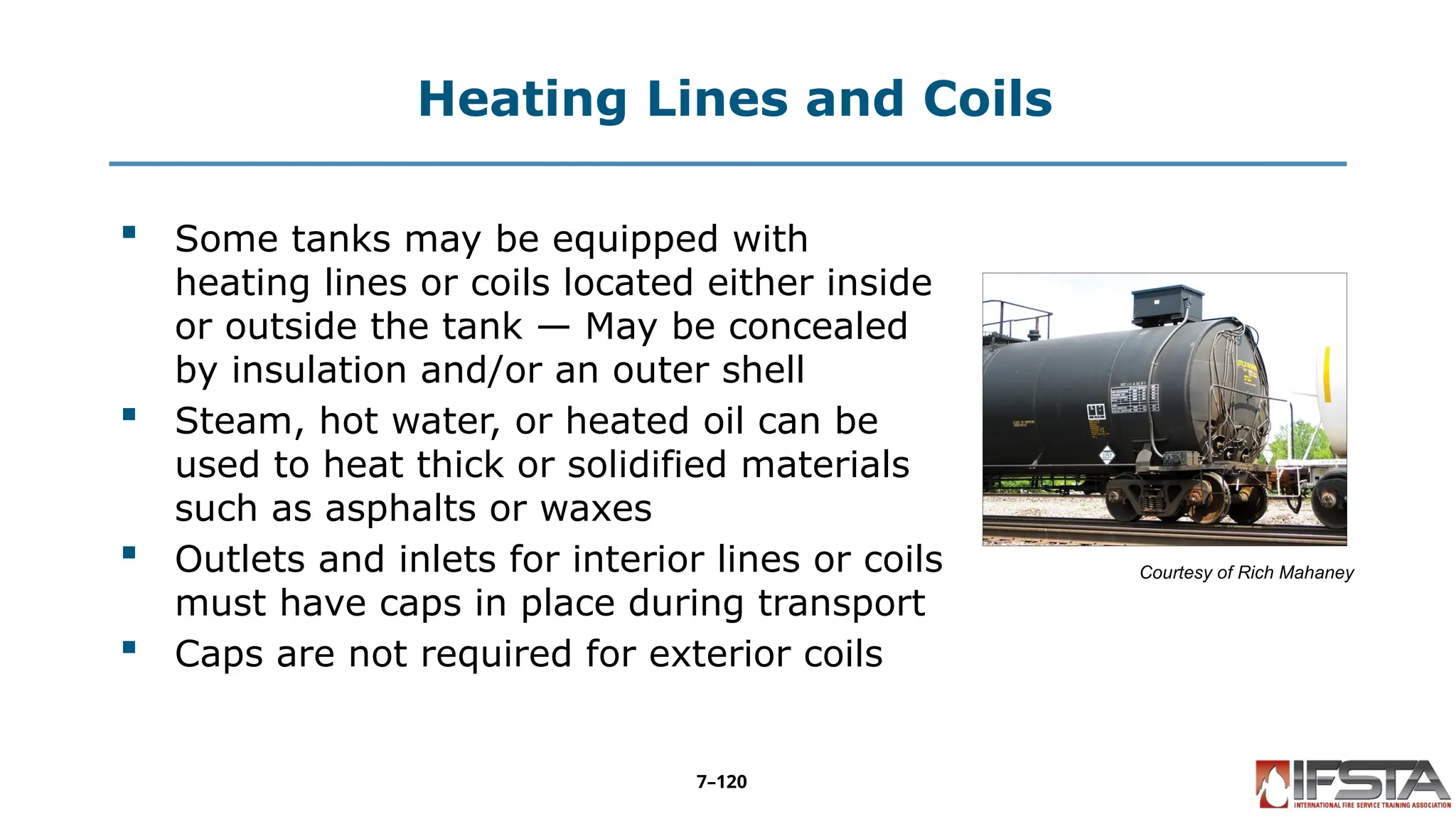
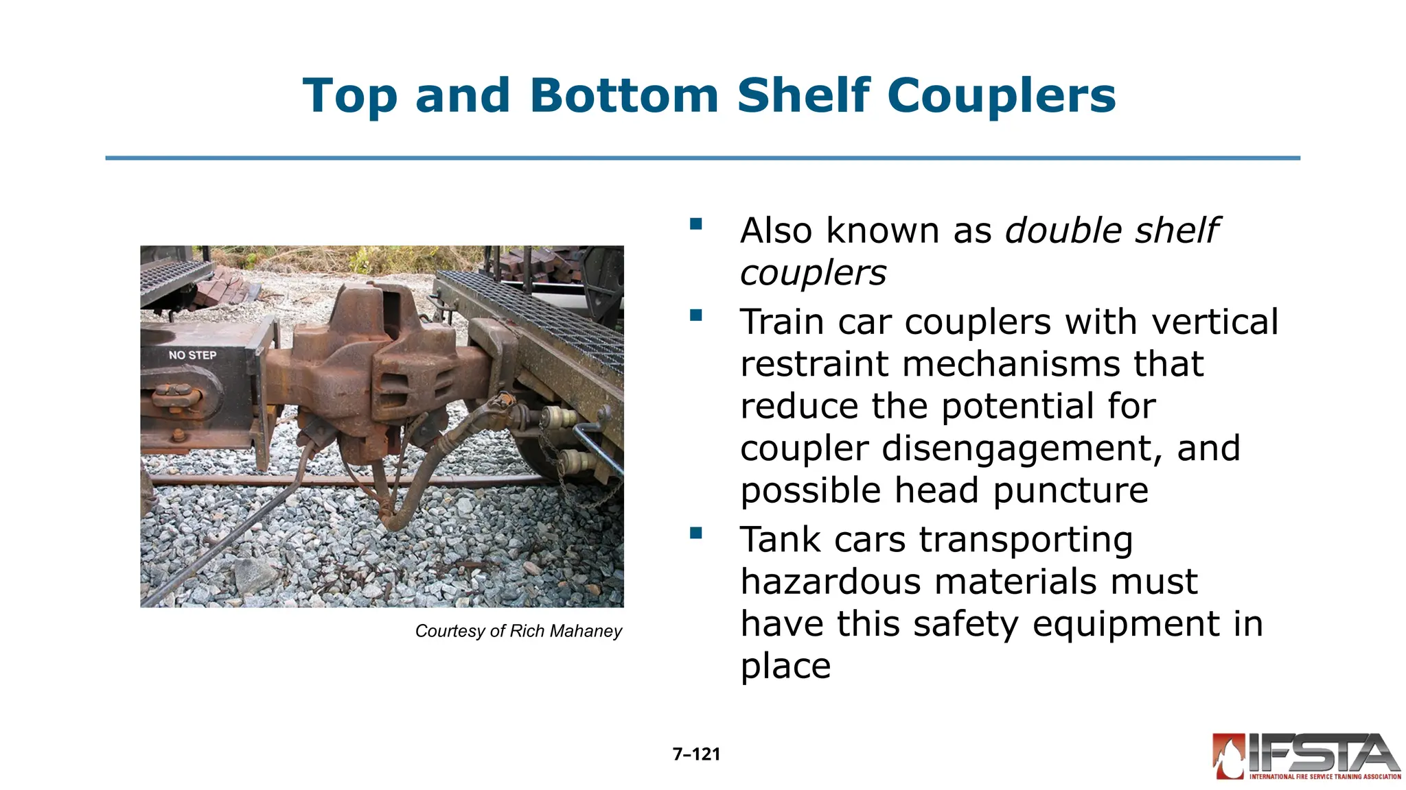


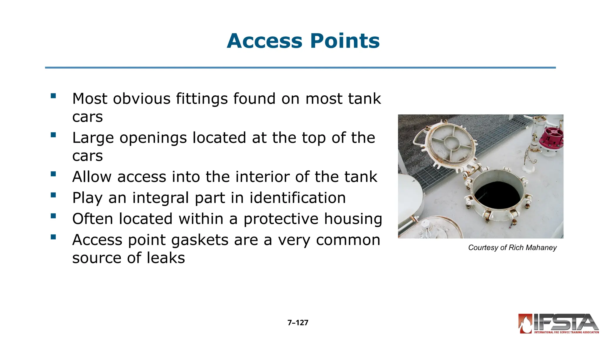
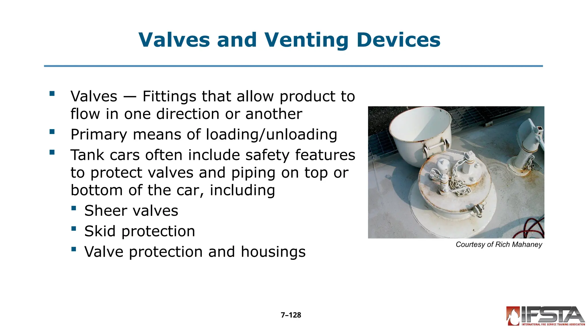
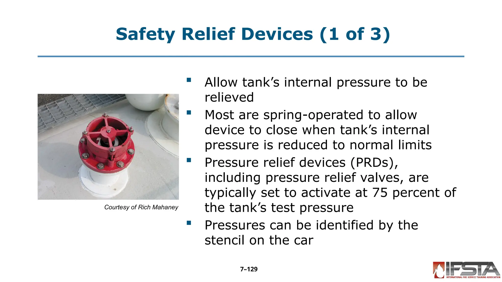
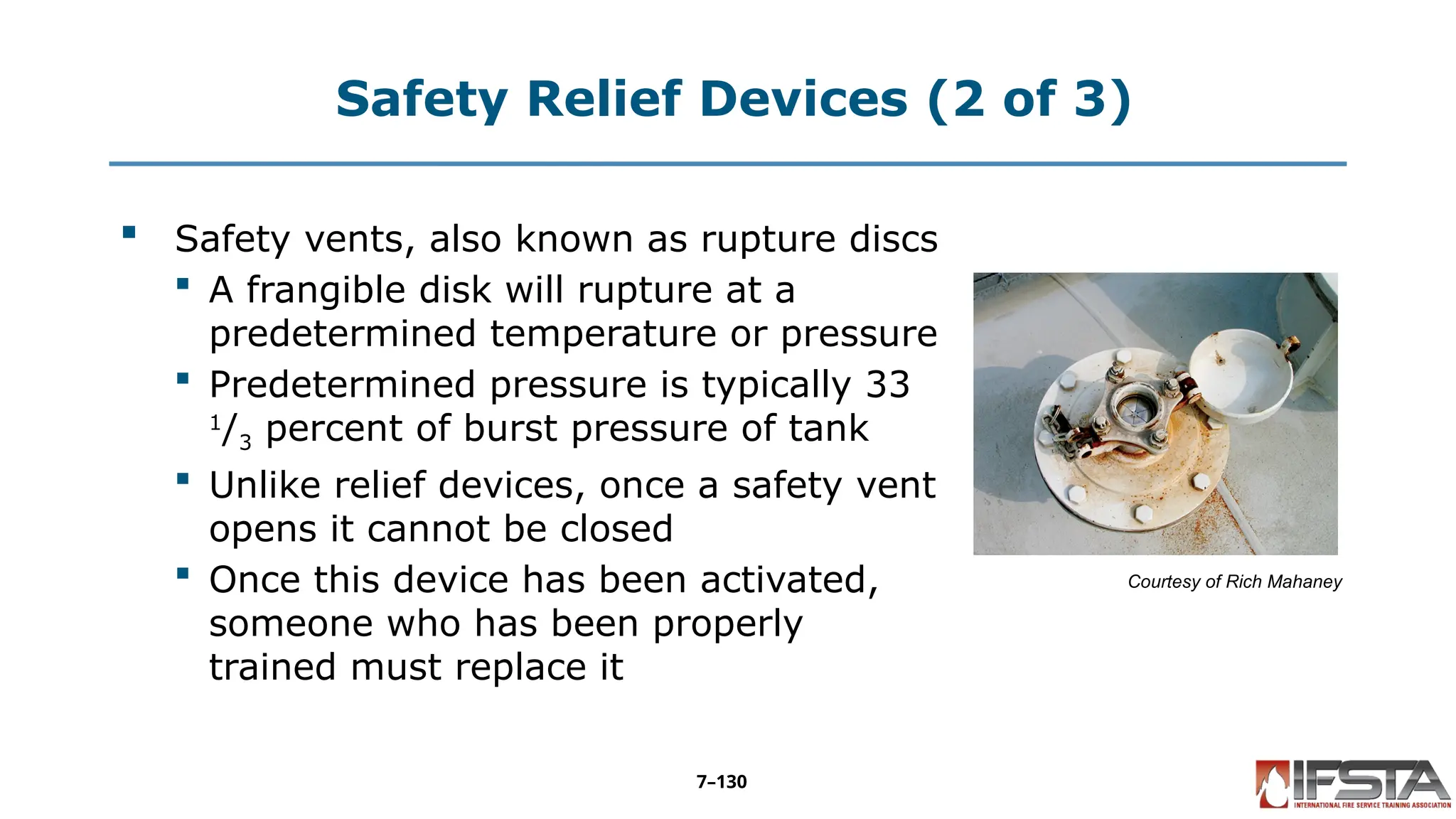
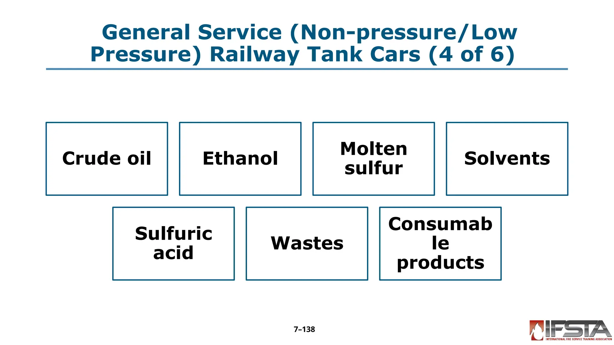
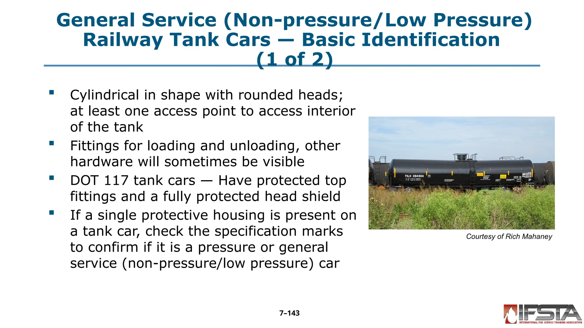
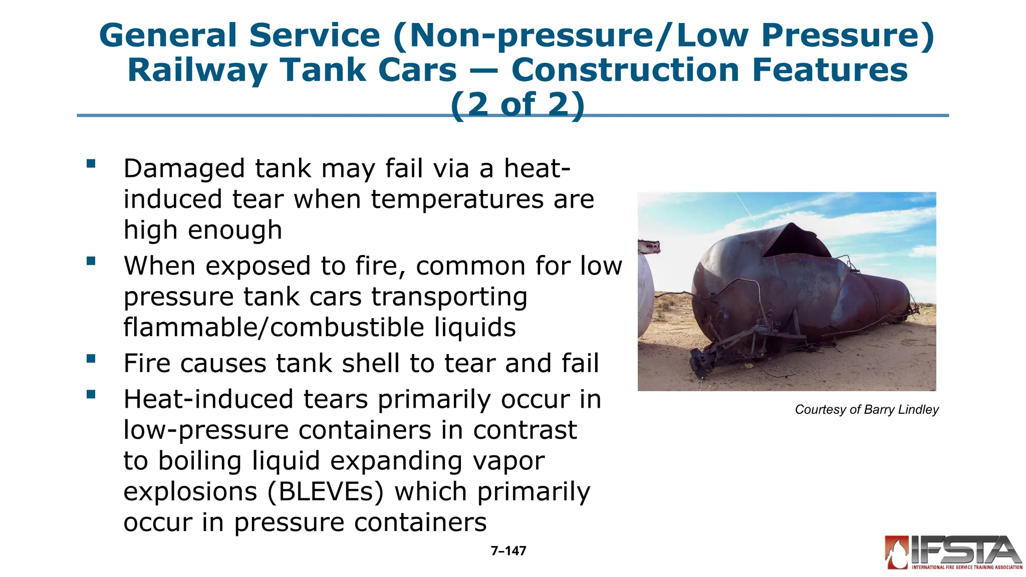
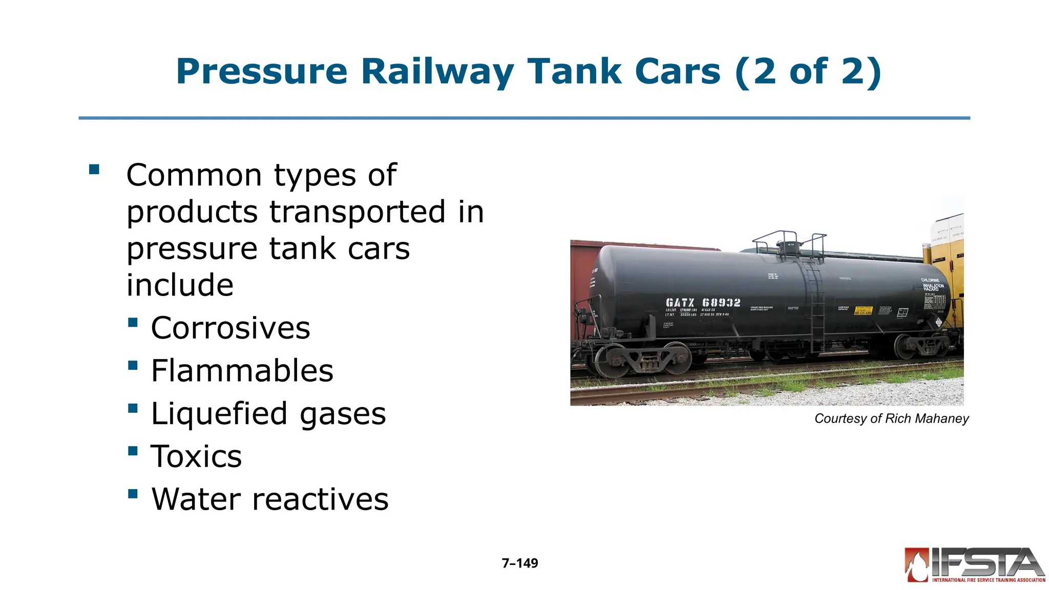
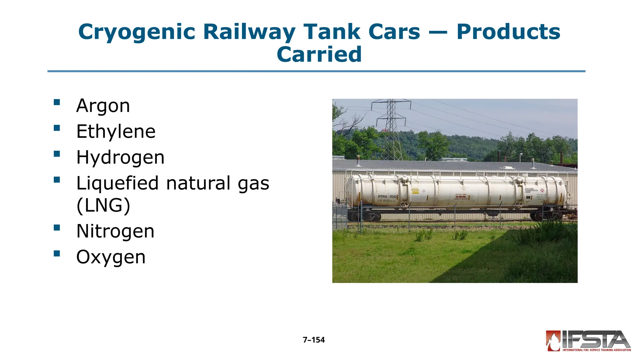
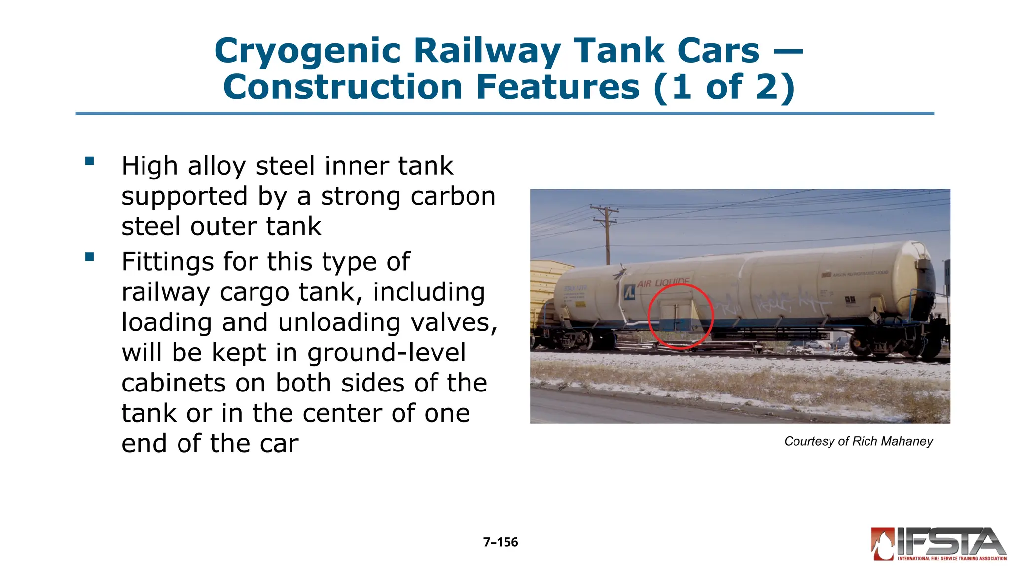
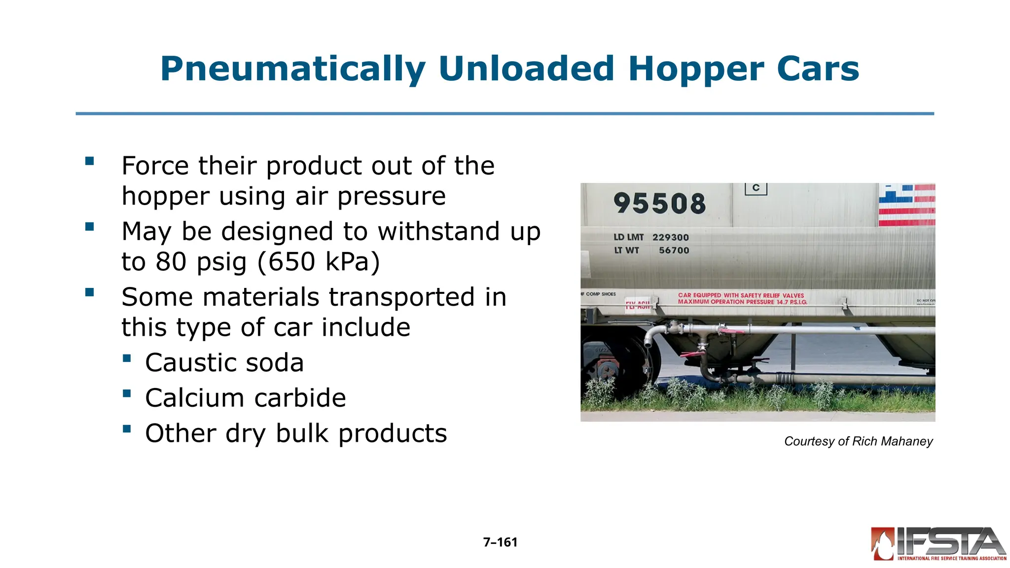
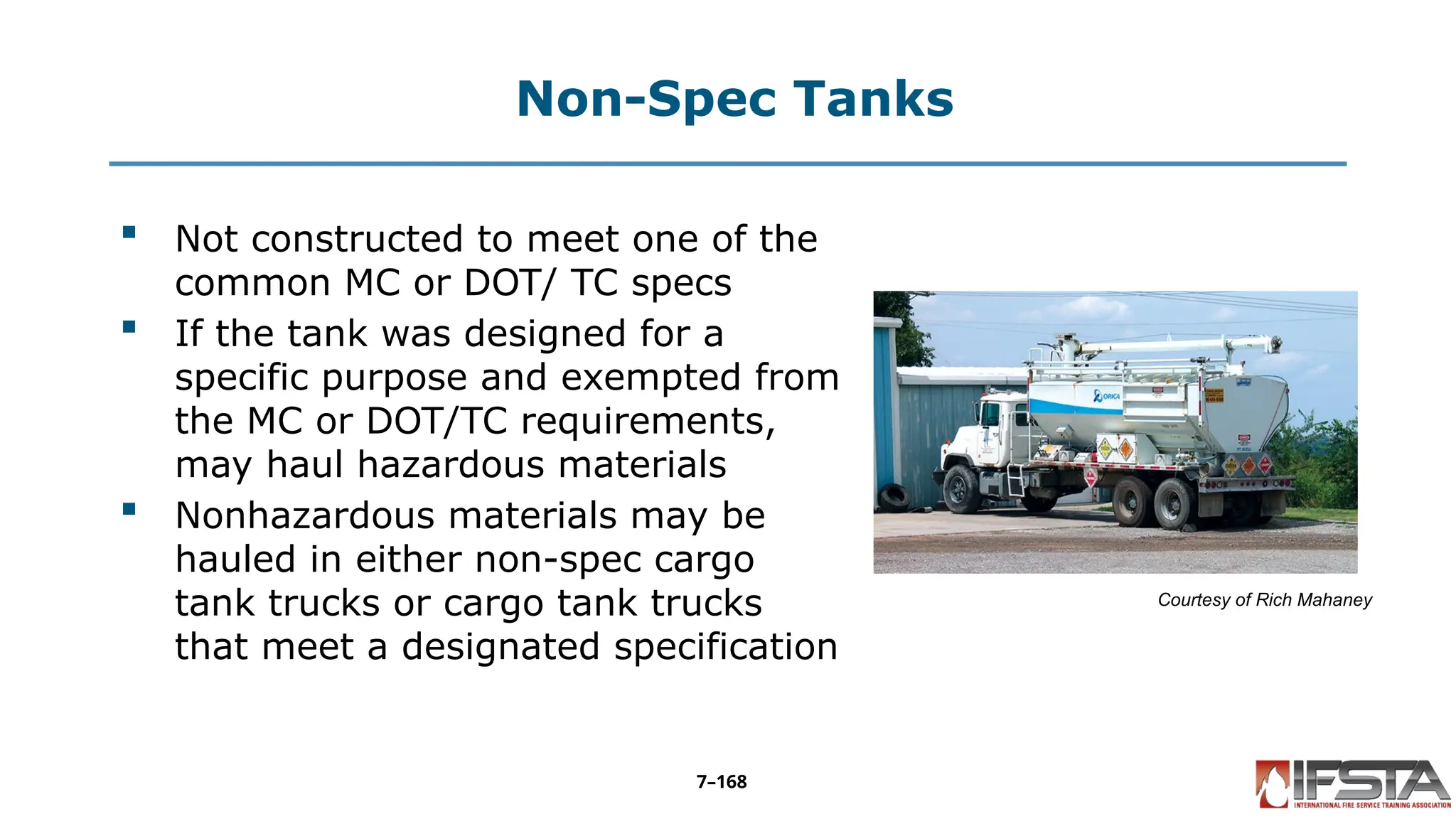


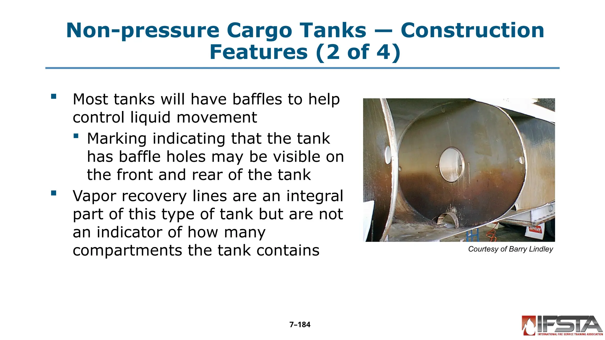
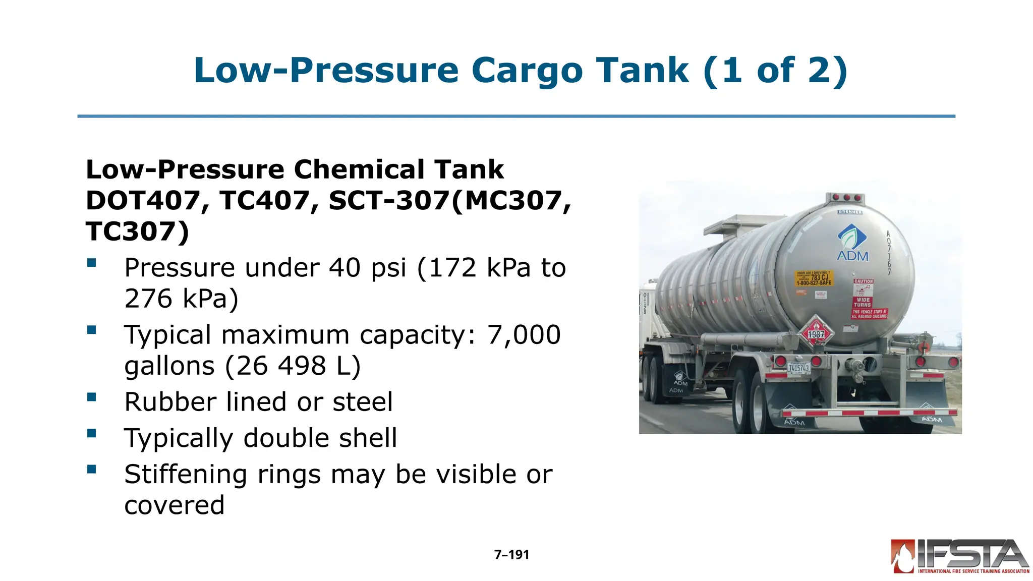
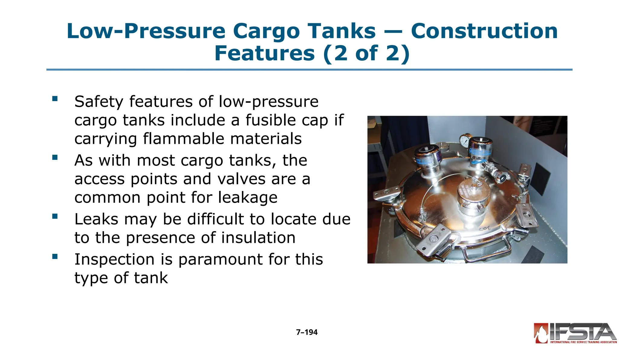
![Corrosive Liquid Tank — Basic
Identification (2 of 3)
Corrosive Liquid Tank DOT412,
TC412, SCT-412(MC312, TC312)
Pressure less than 75 psi (517 kPa)
Typical maximum capacity: 7,000
gallons (26 498 L) [per NFPA]
Rubber lined or steel
Typically single compartment
Small-diameter round shape
Exterior stiffening rings may be visible
on uninsulated tanks
7–198](https://image.slidesharecdn.com/ifstahmt3edcontainerassessment-251009160054-4432bf57/75/Container-Assessment-from-the-fist-manual-198-2048.jpg)
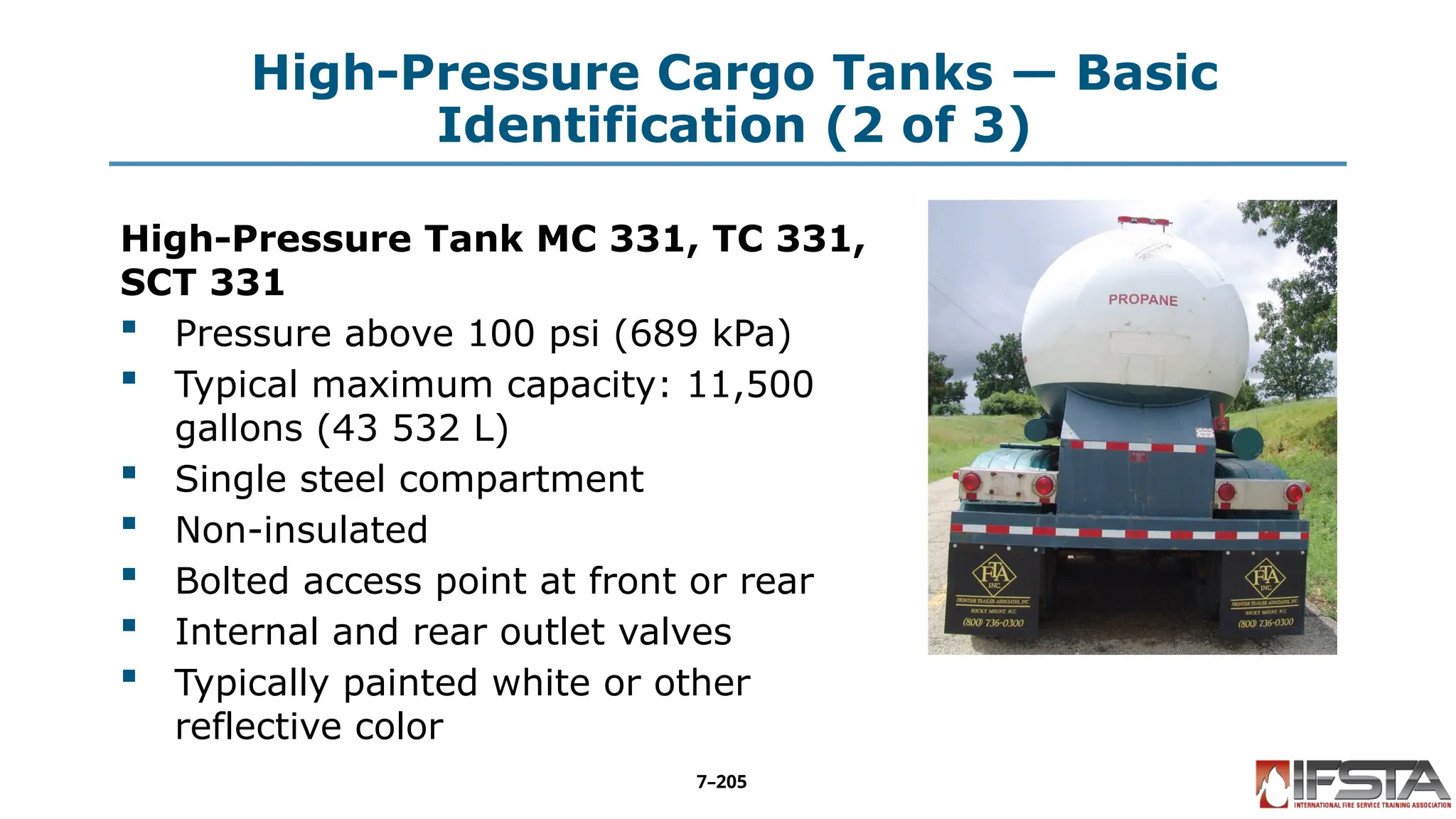
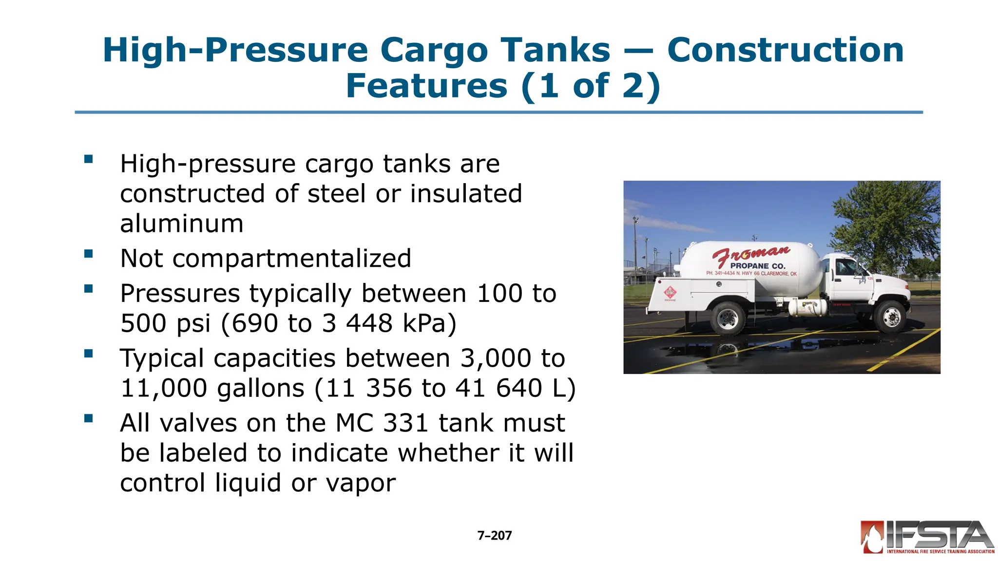
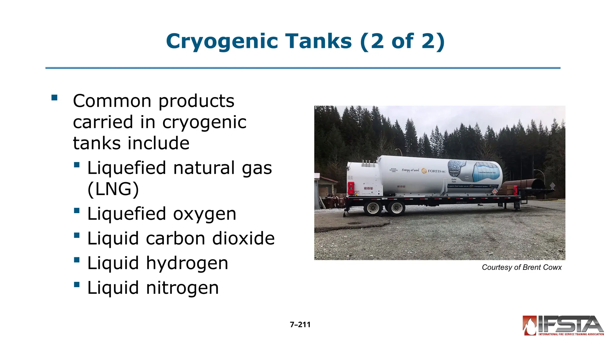
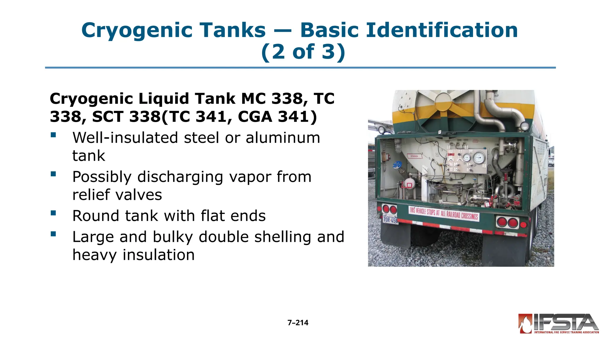
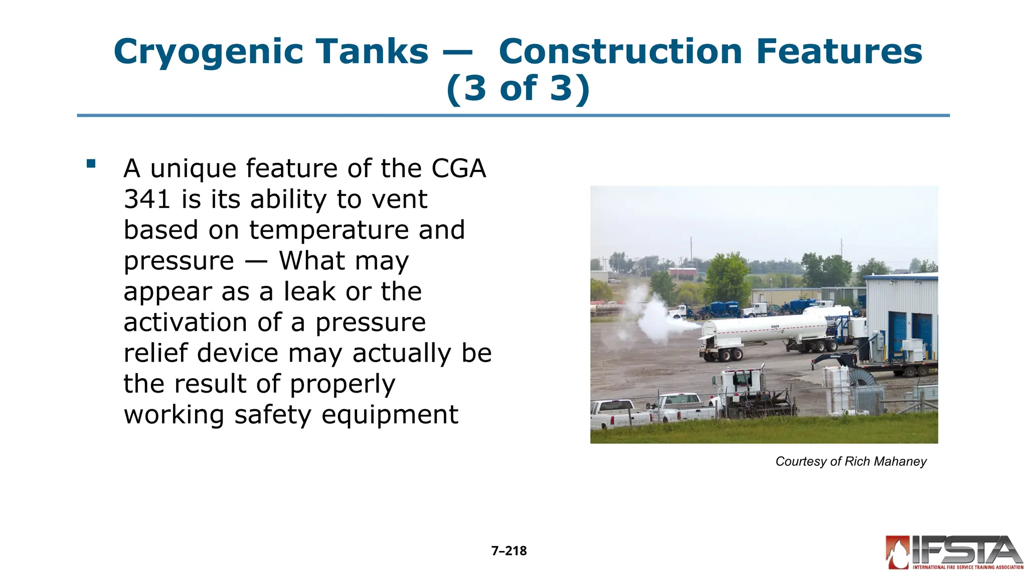
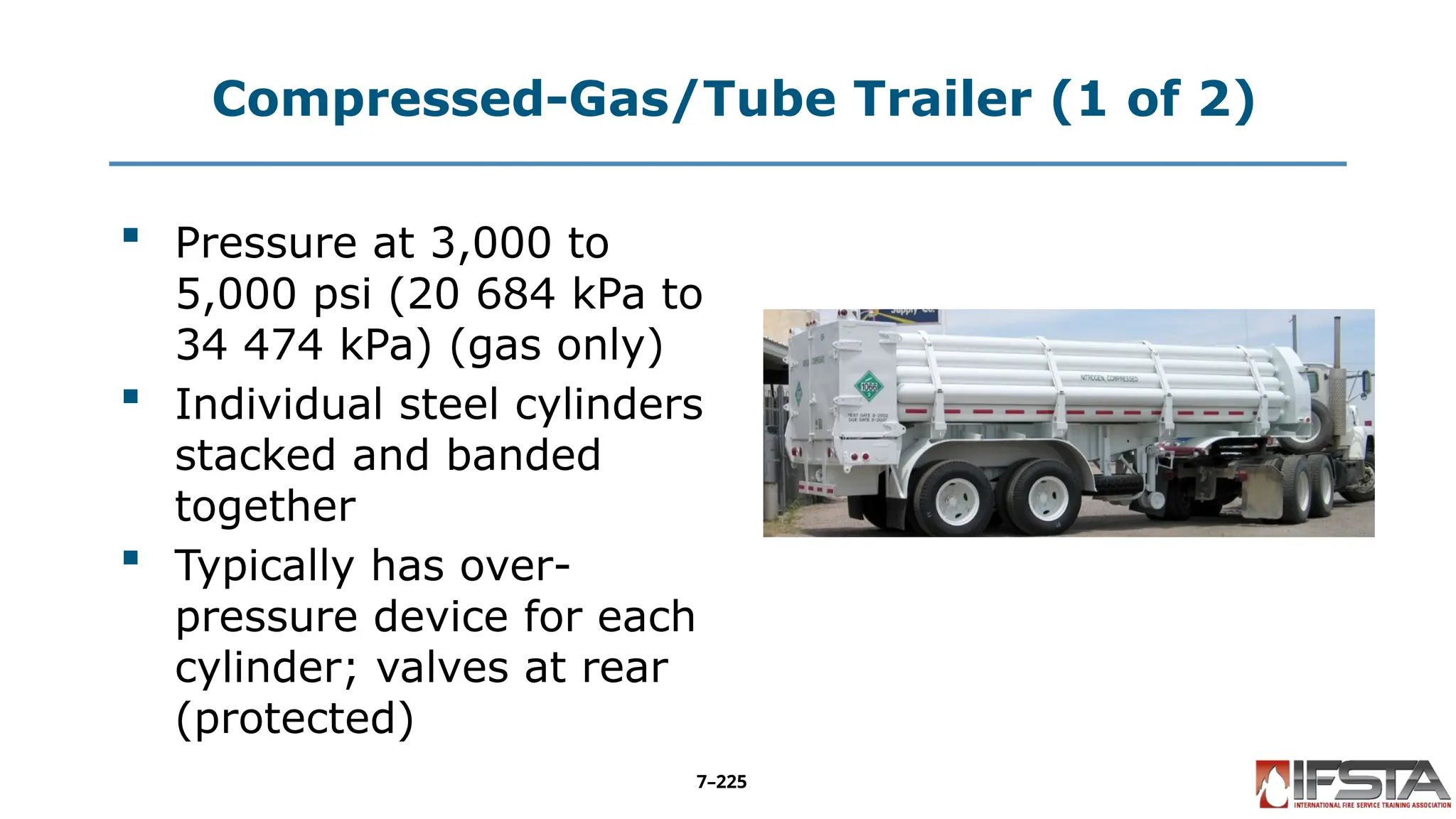

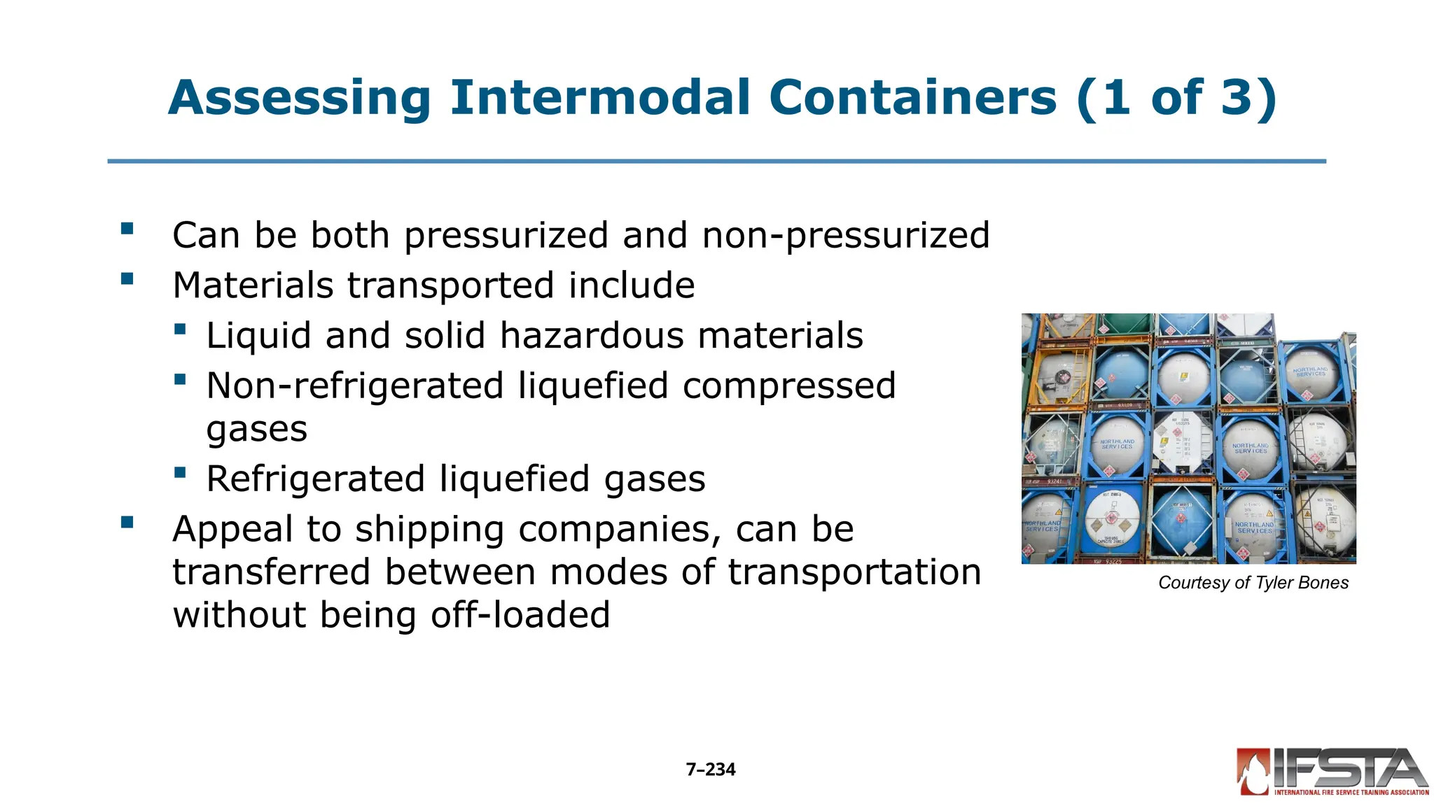

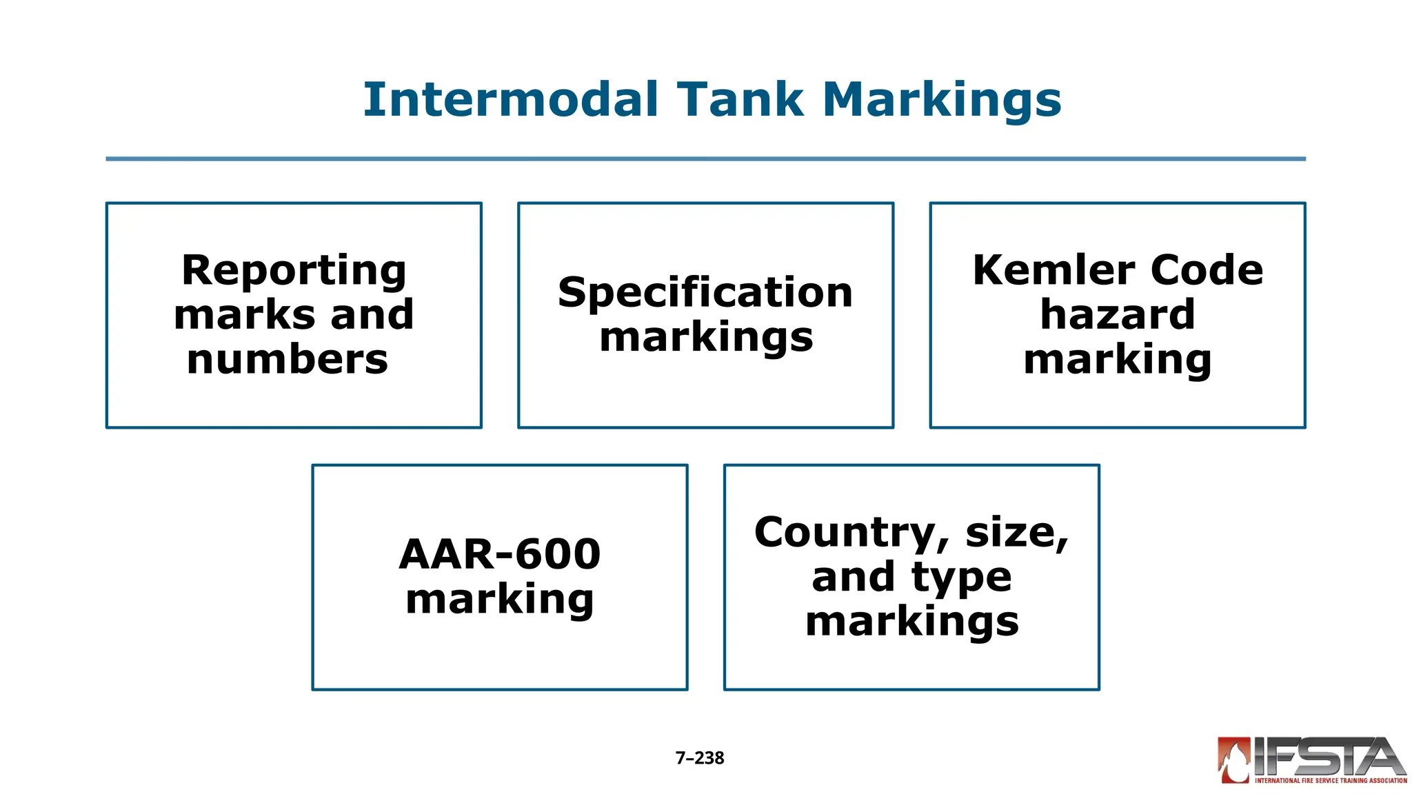
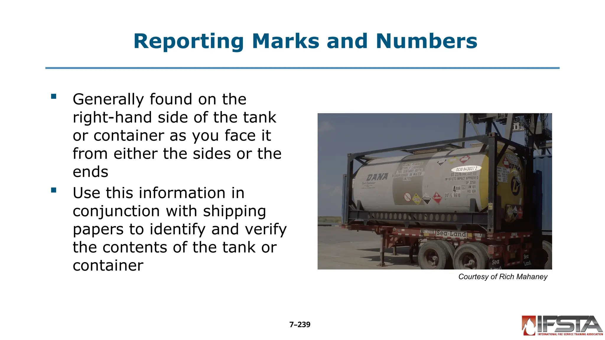
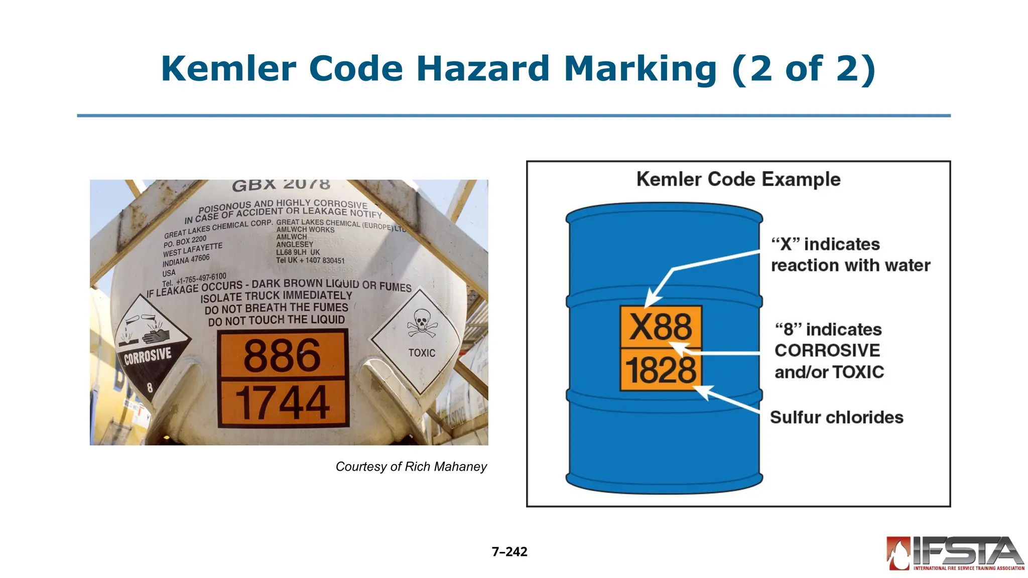
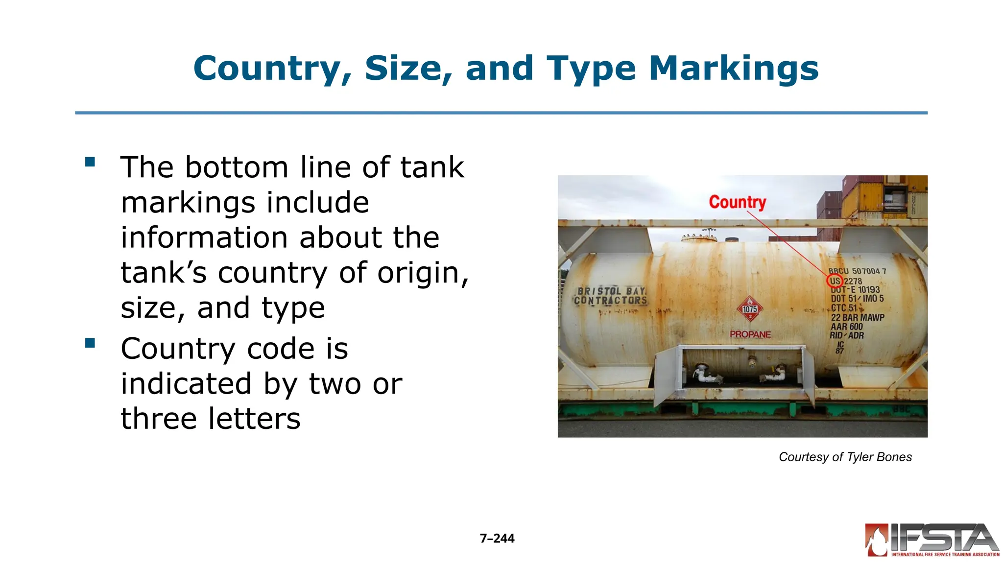

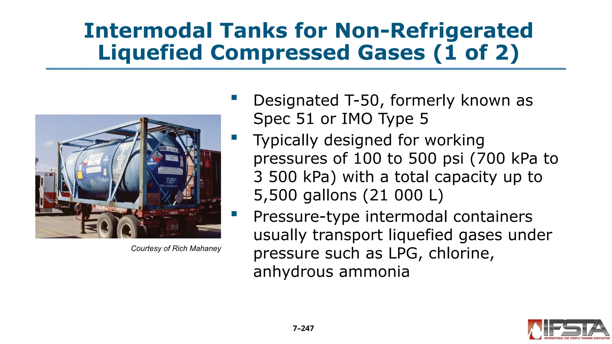
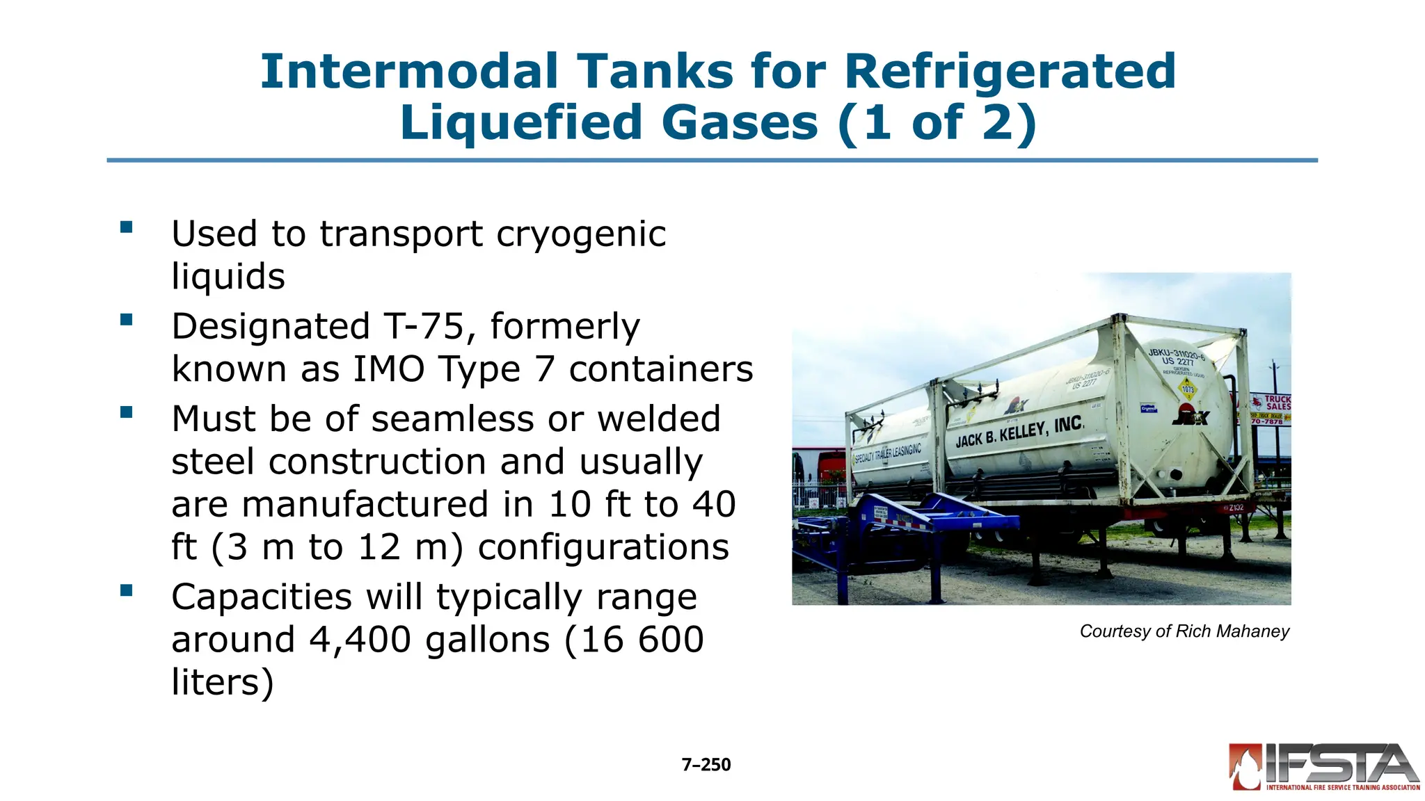
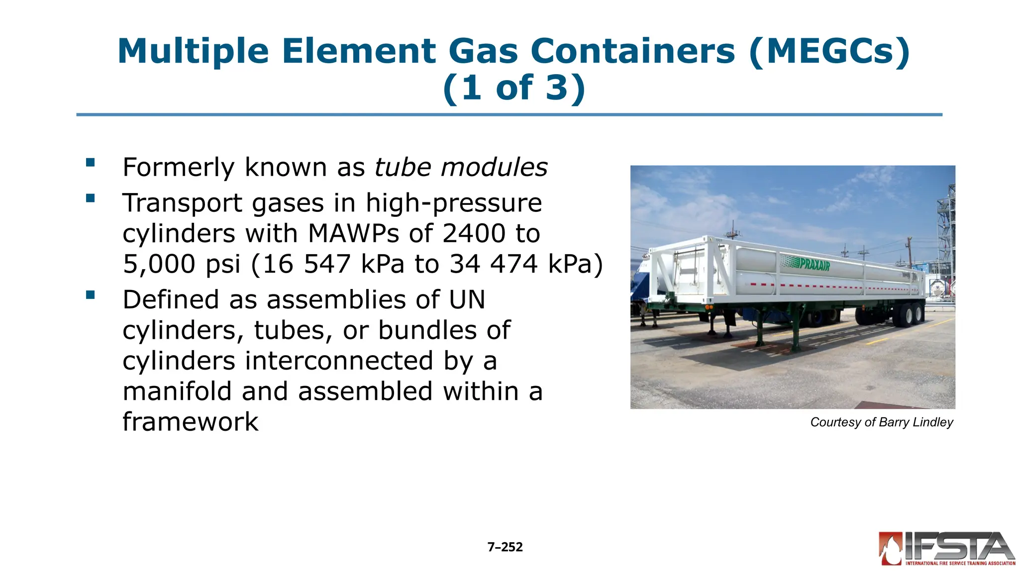
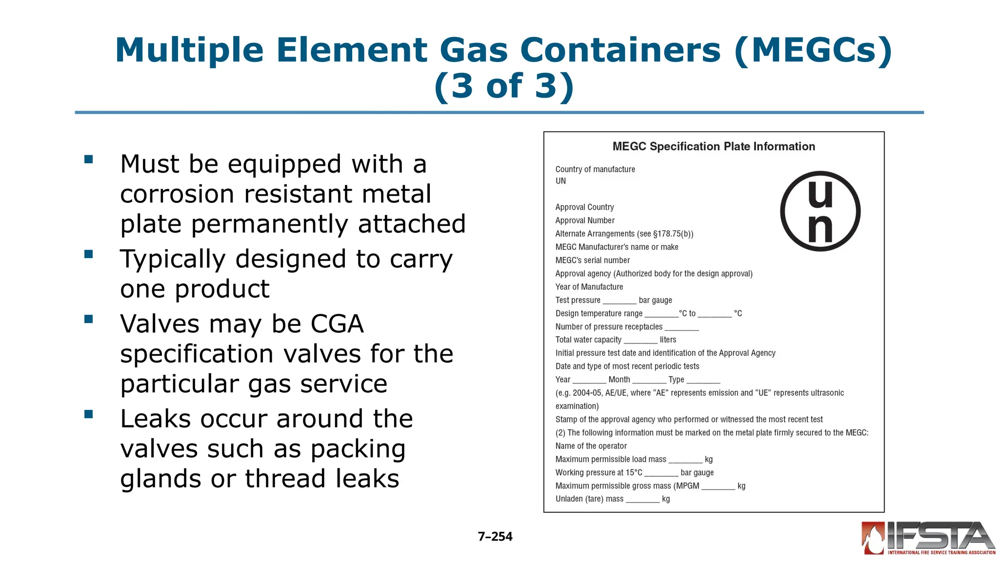
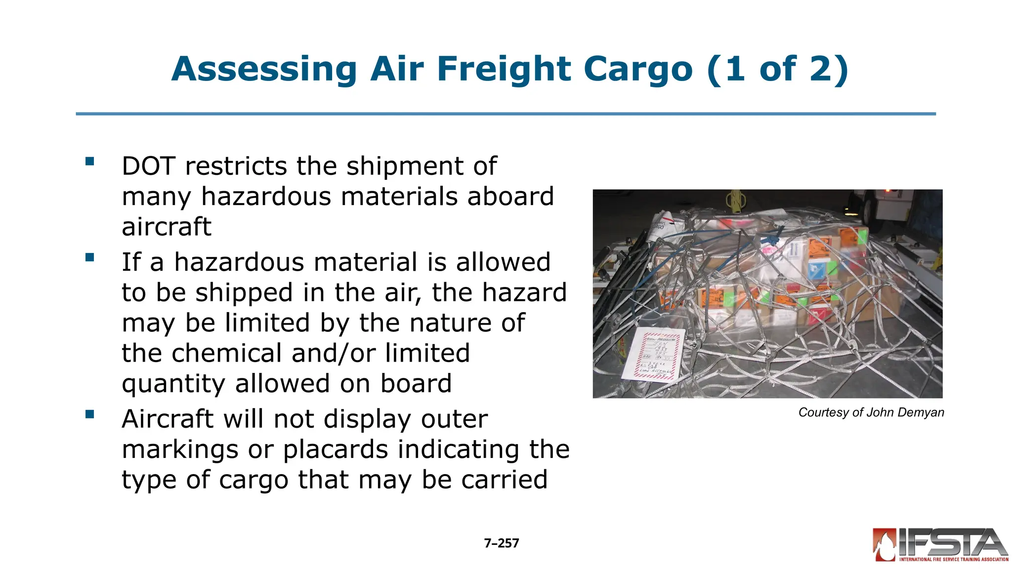

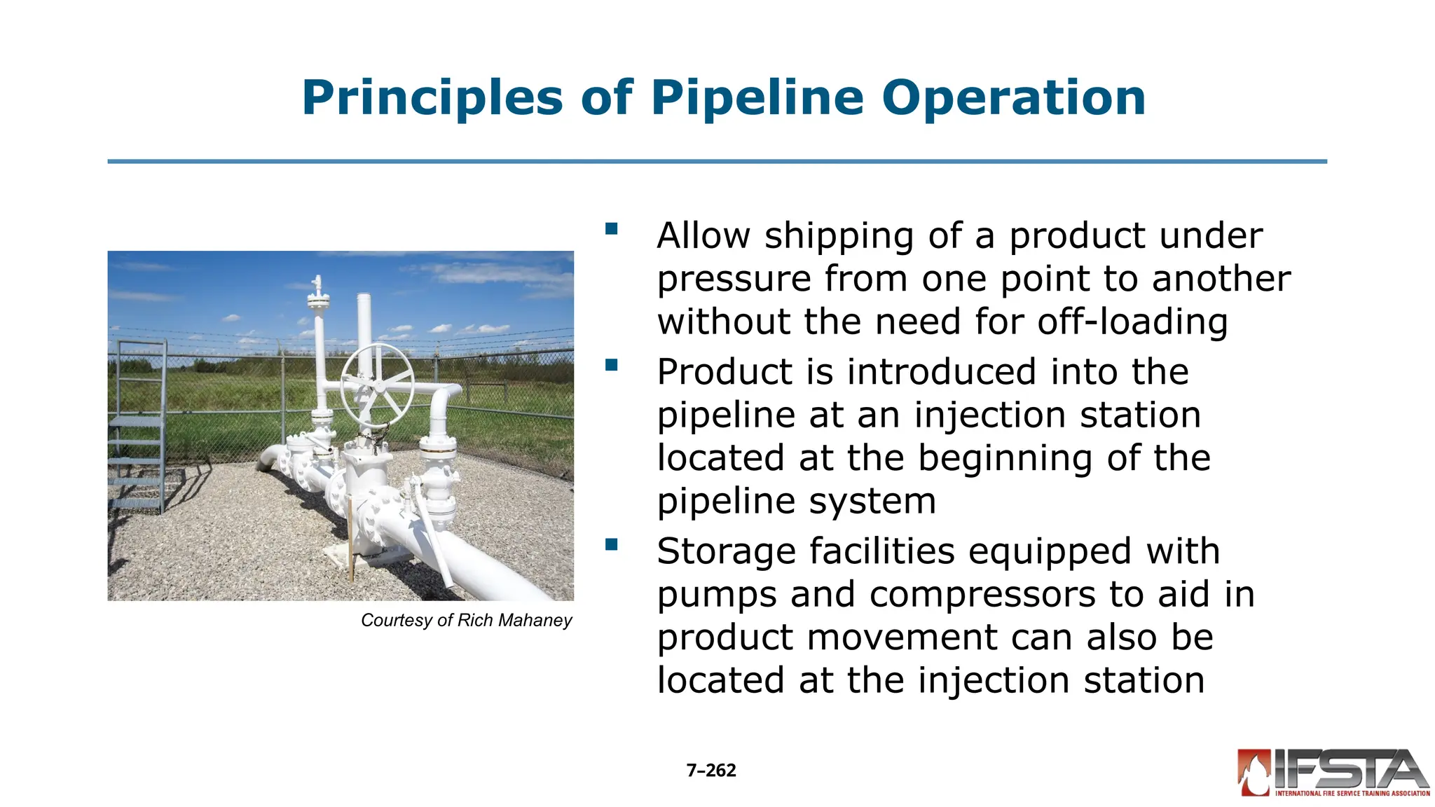
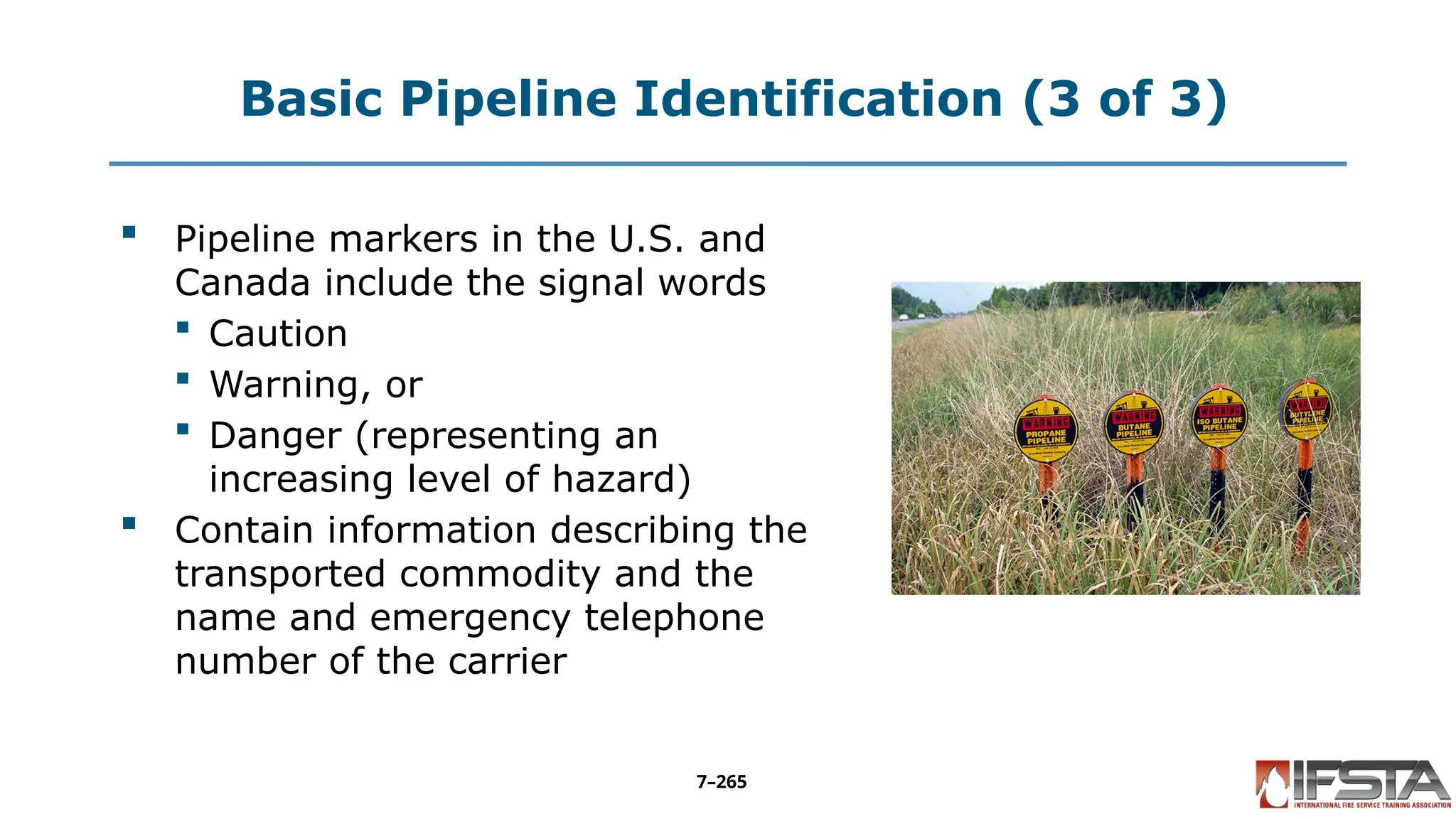
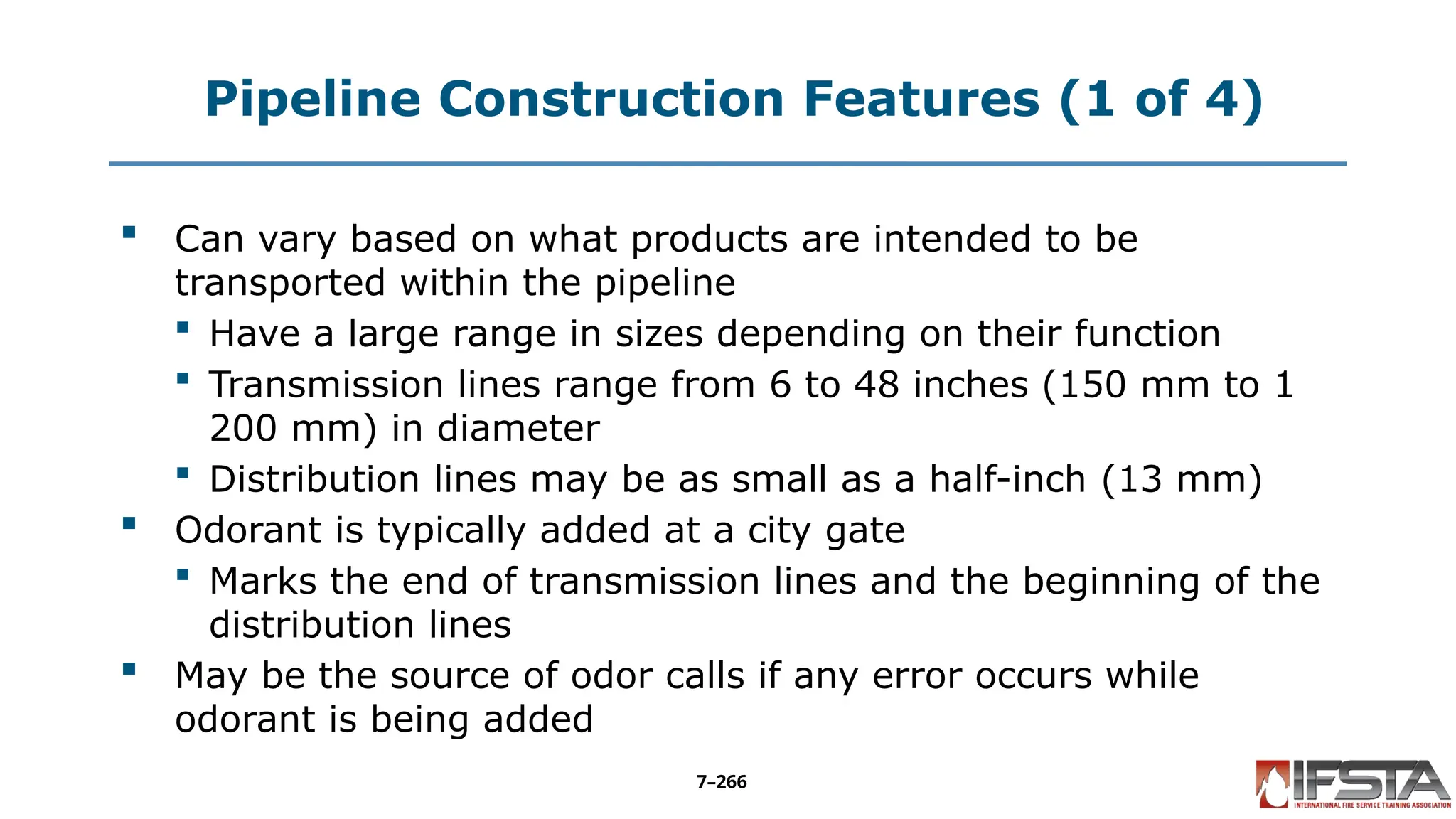
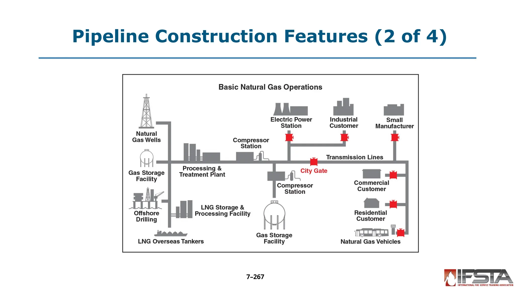
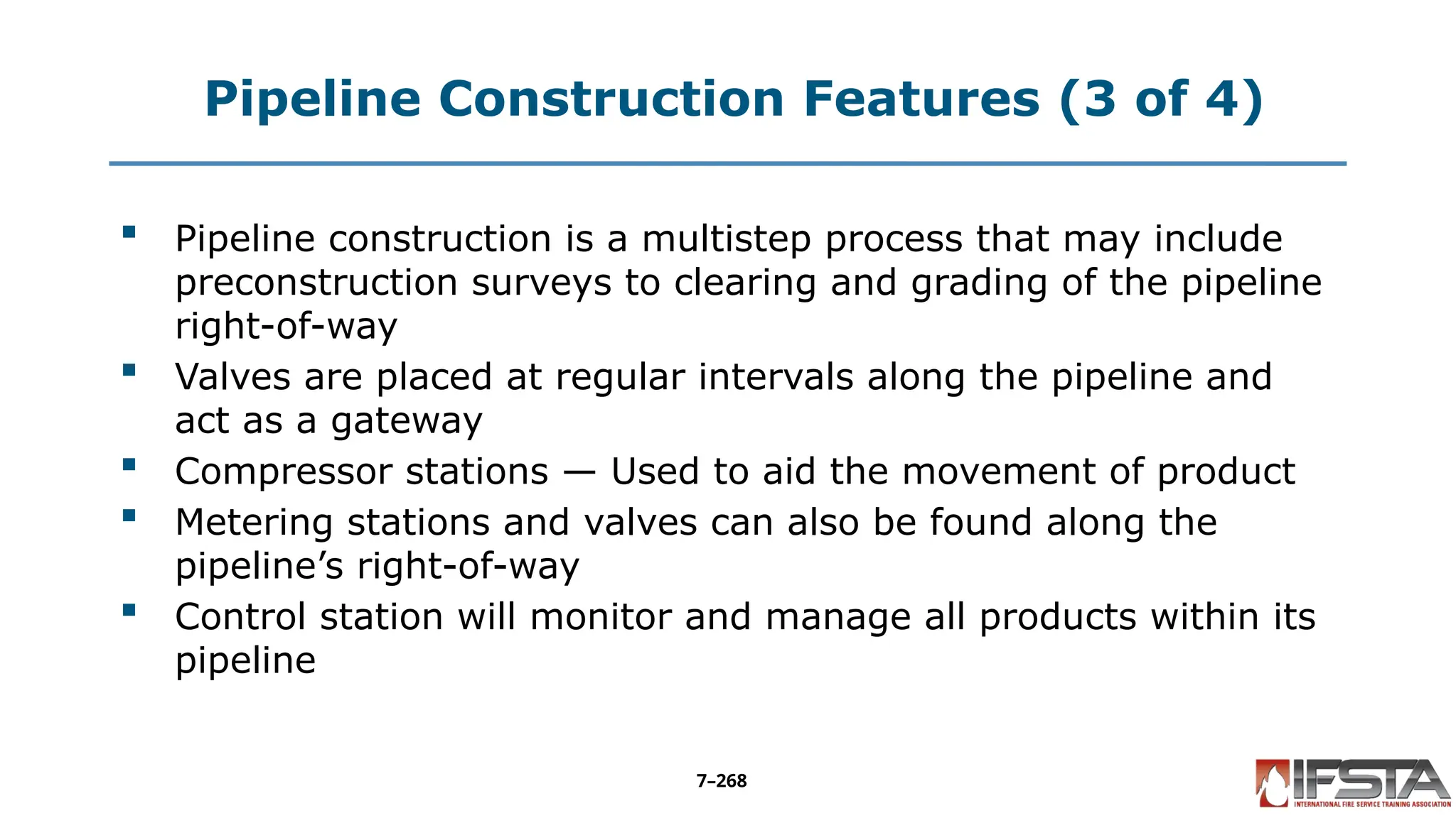
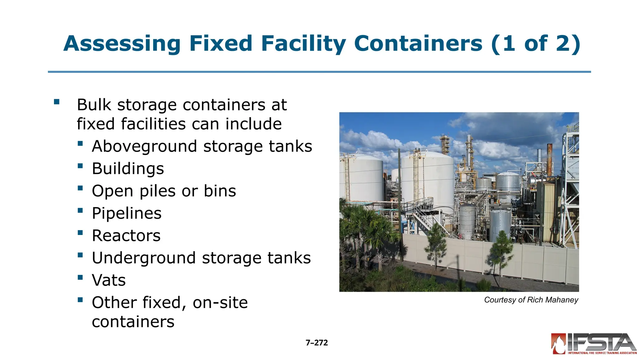
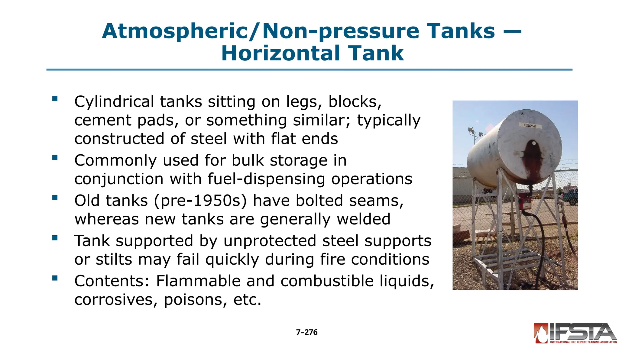
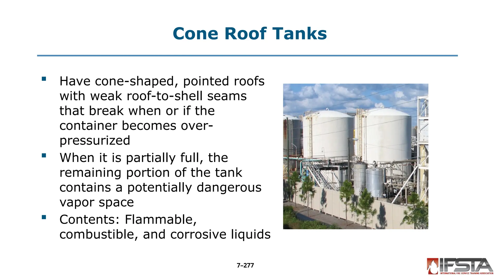

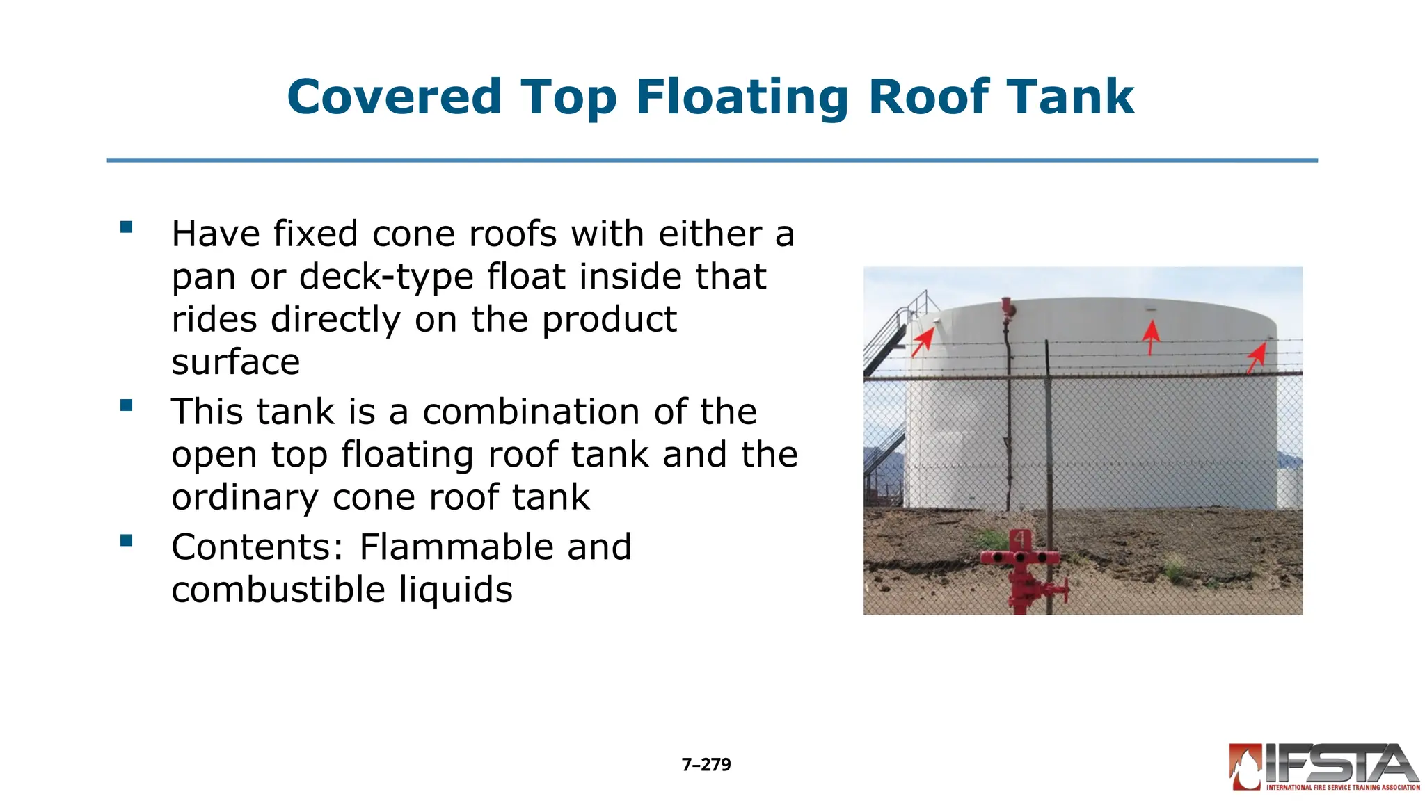
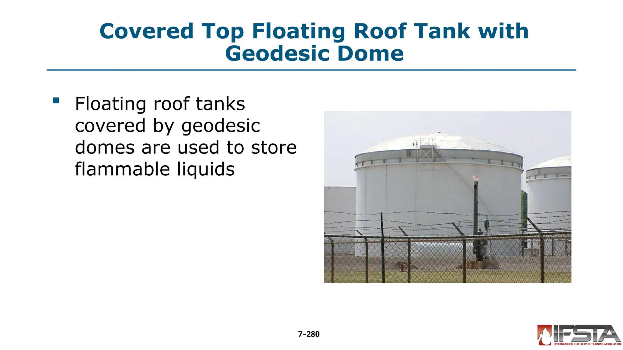
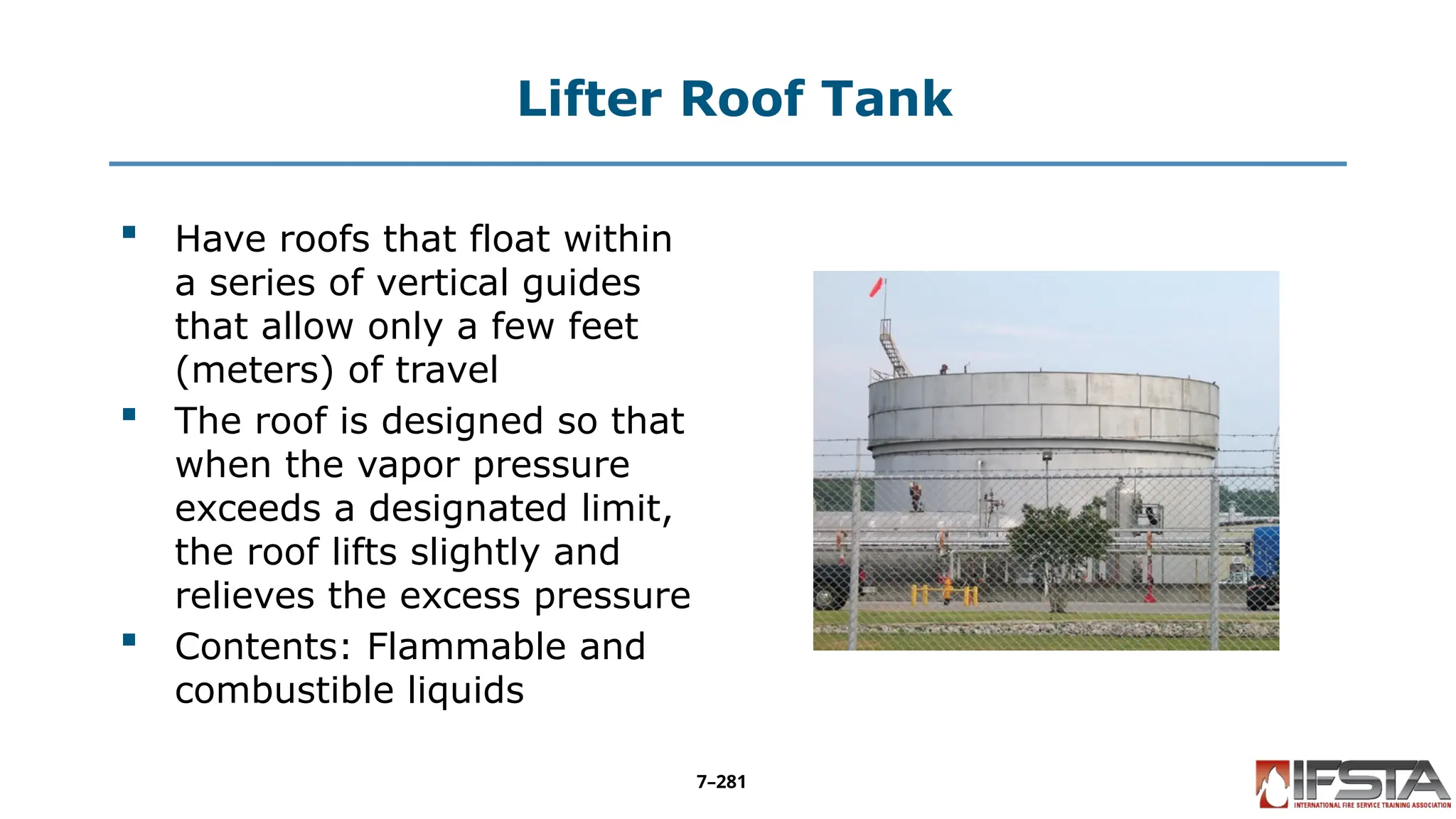
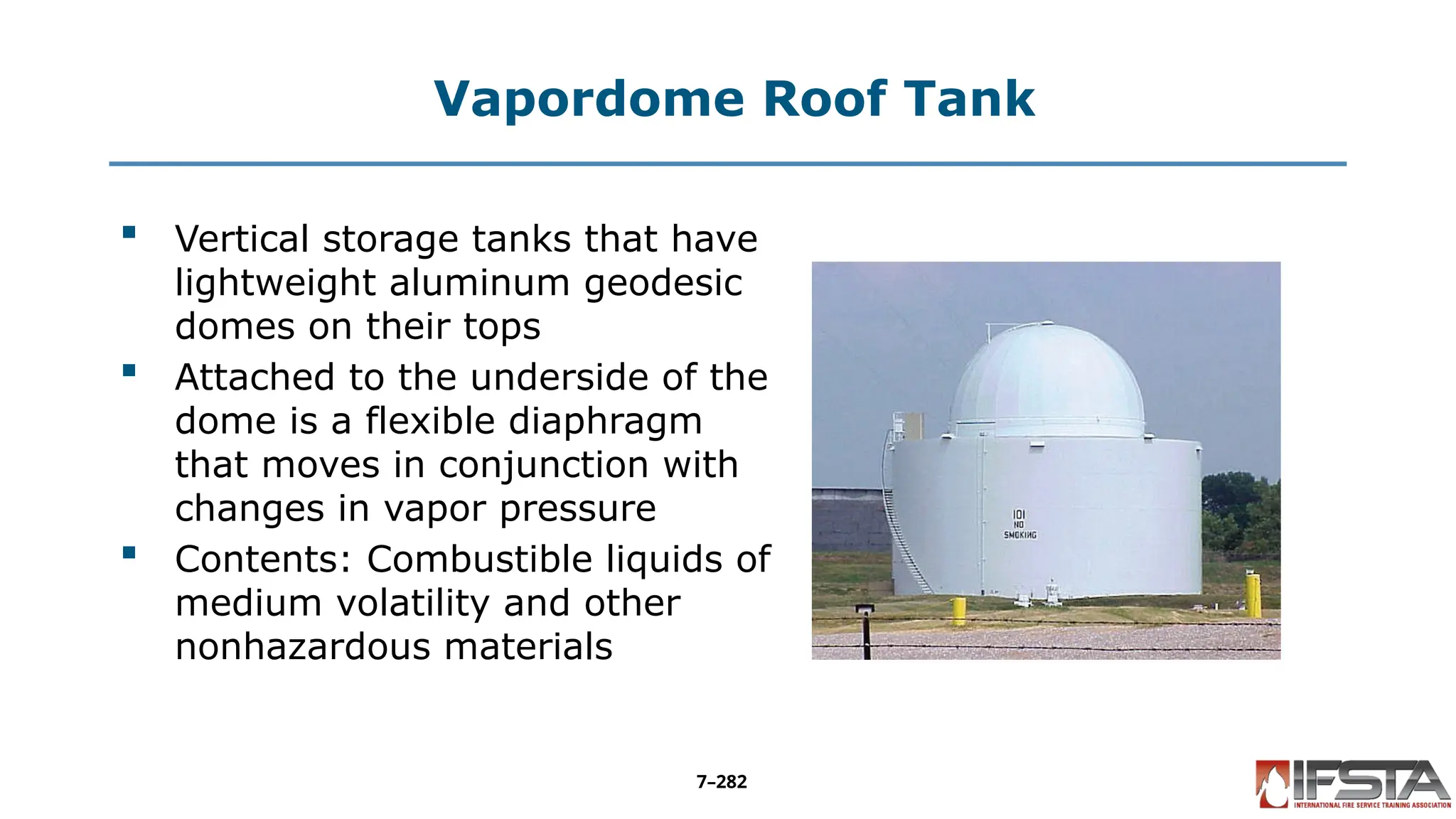
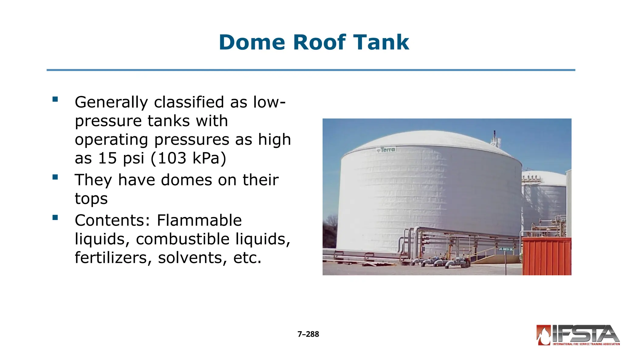
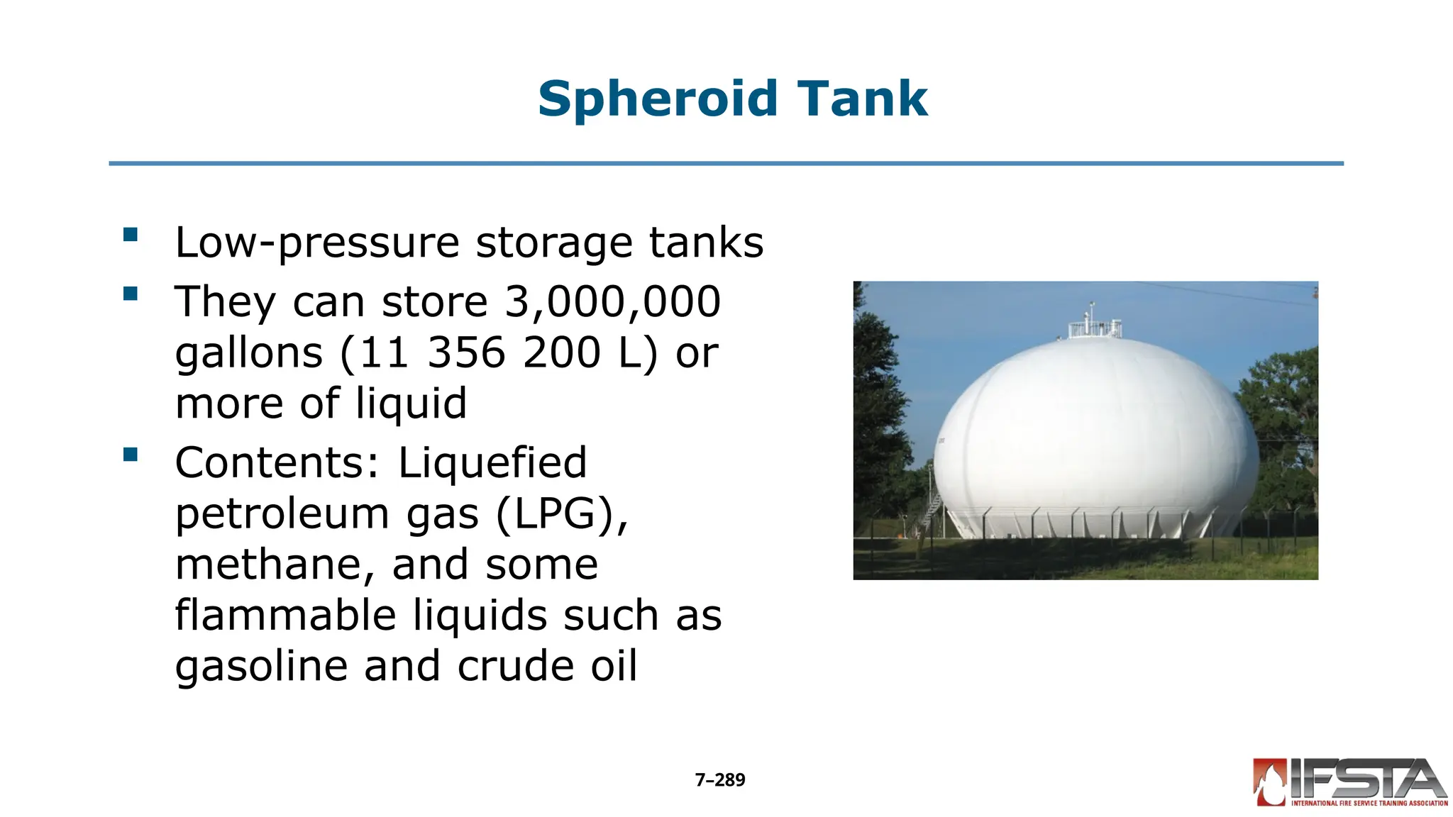
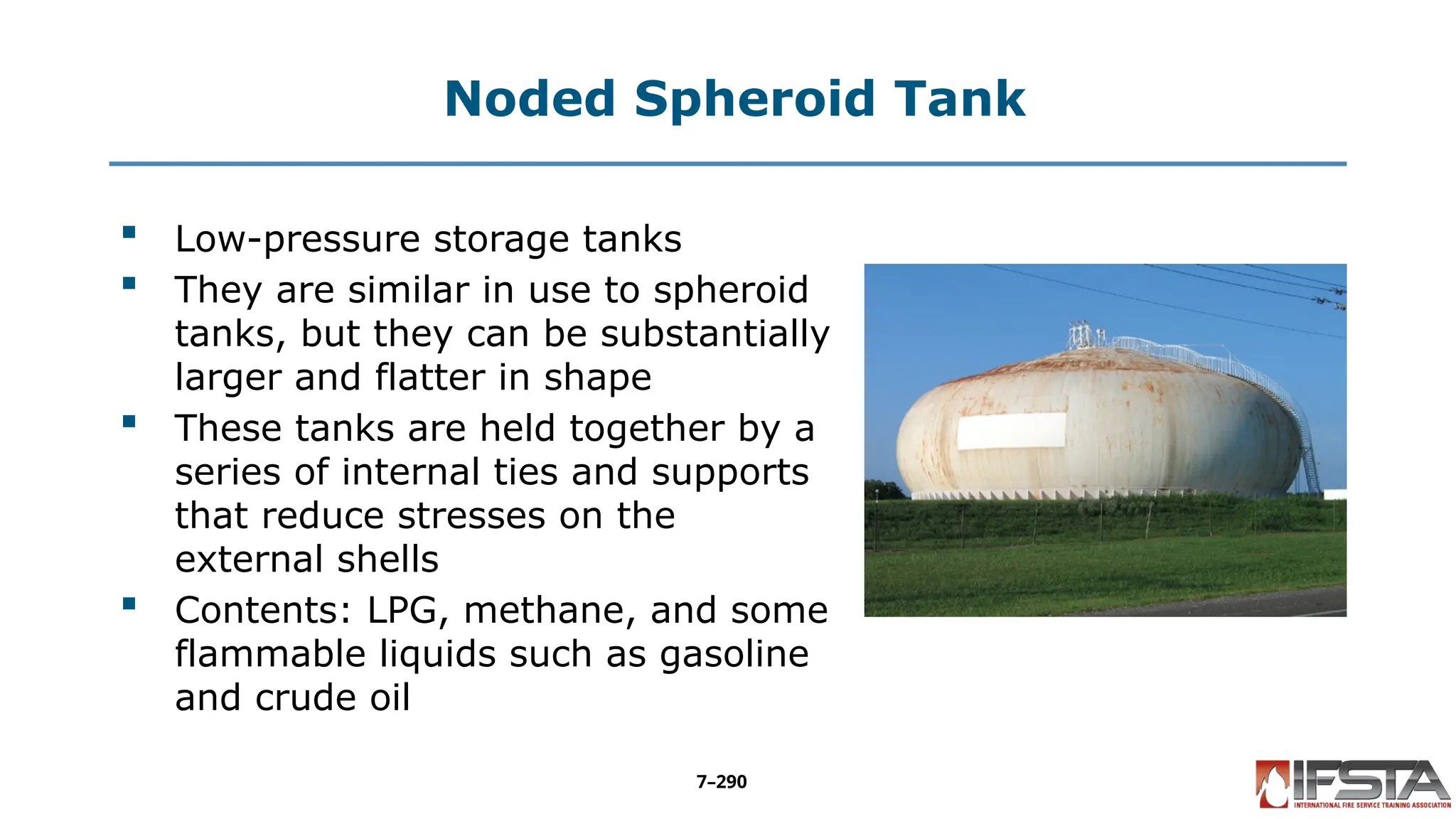
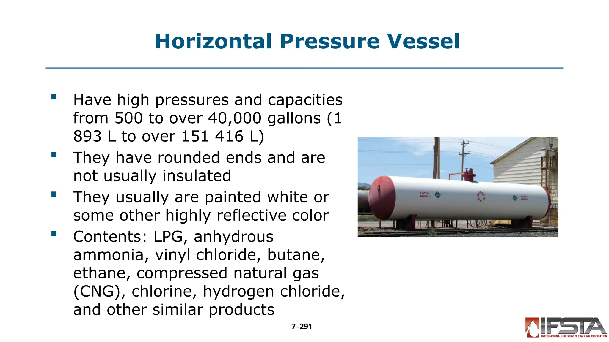
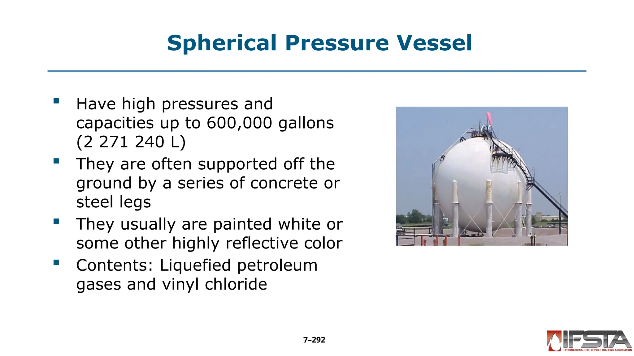
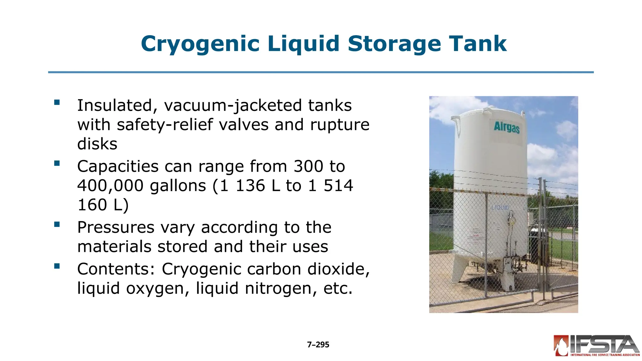
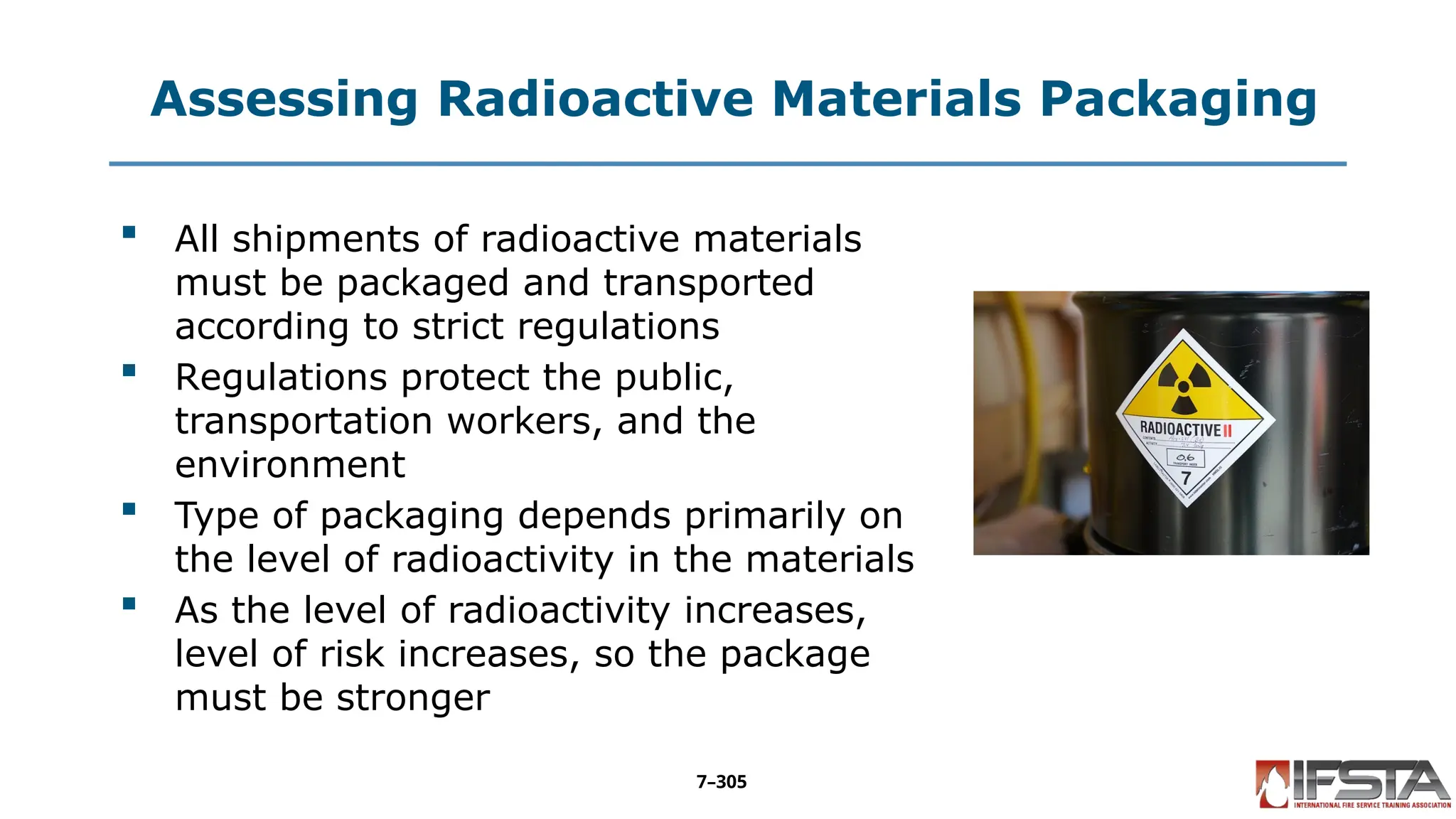
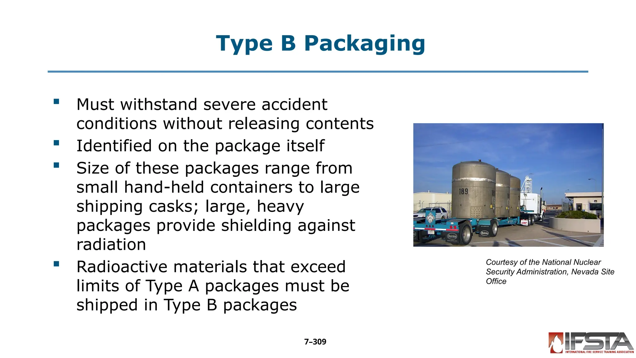
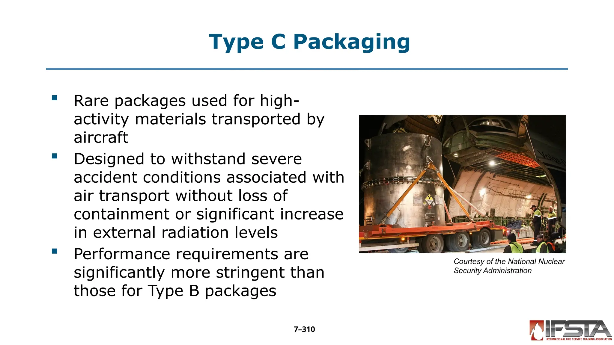
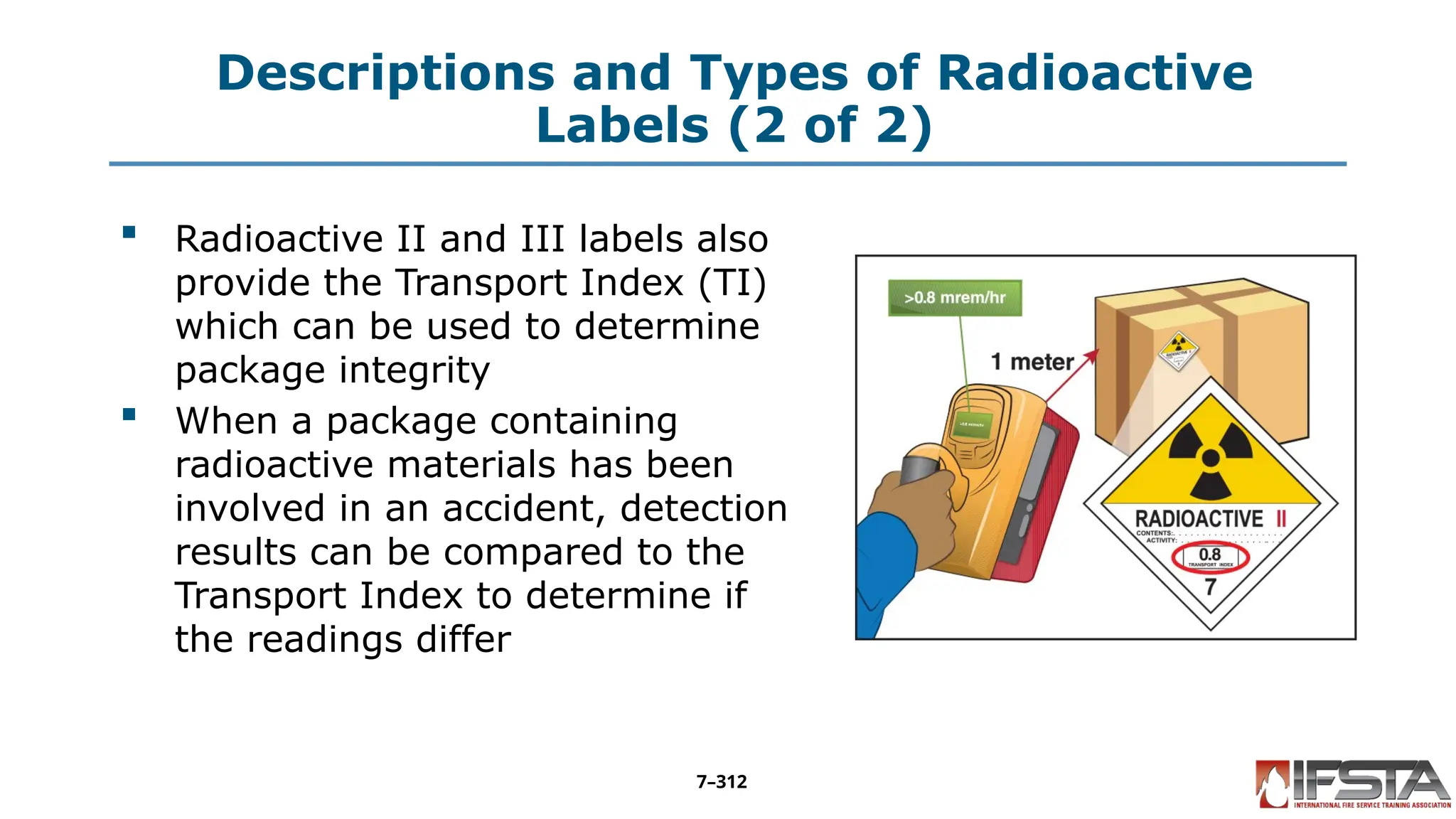


![Corrosive Liquid Tank — Basic
Identification (2 of 3)
Corrosive Liquid Tank DOT412,
TC412, SCT-412(MC312, TC312)
Pressure less than 75 psi (517 kPa)
Typical maximum capacity: 7,000
gallons (26 498 L) [per NFPA]
Rubber lined or steel
Typically single compartment
Small-diameter round shape
Exterior stiffening rings may be visible
on uninsulated tanks
7–198](https://crownmelresort.com/image.slidesharecdn.com/ifstahmt3edcontainerassessment-251009160054-4432bf57/75/Container-Assessment-from-the-fist-manual-198-2048.jpg)


