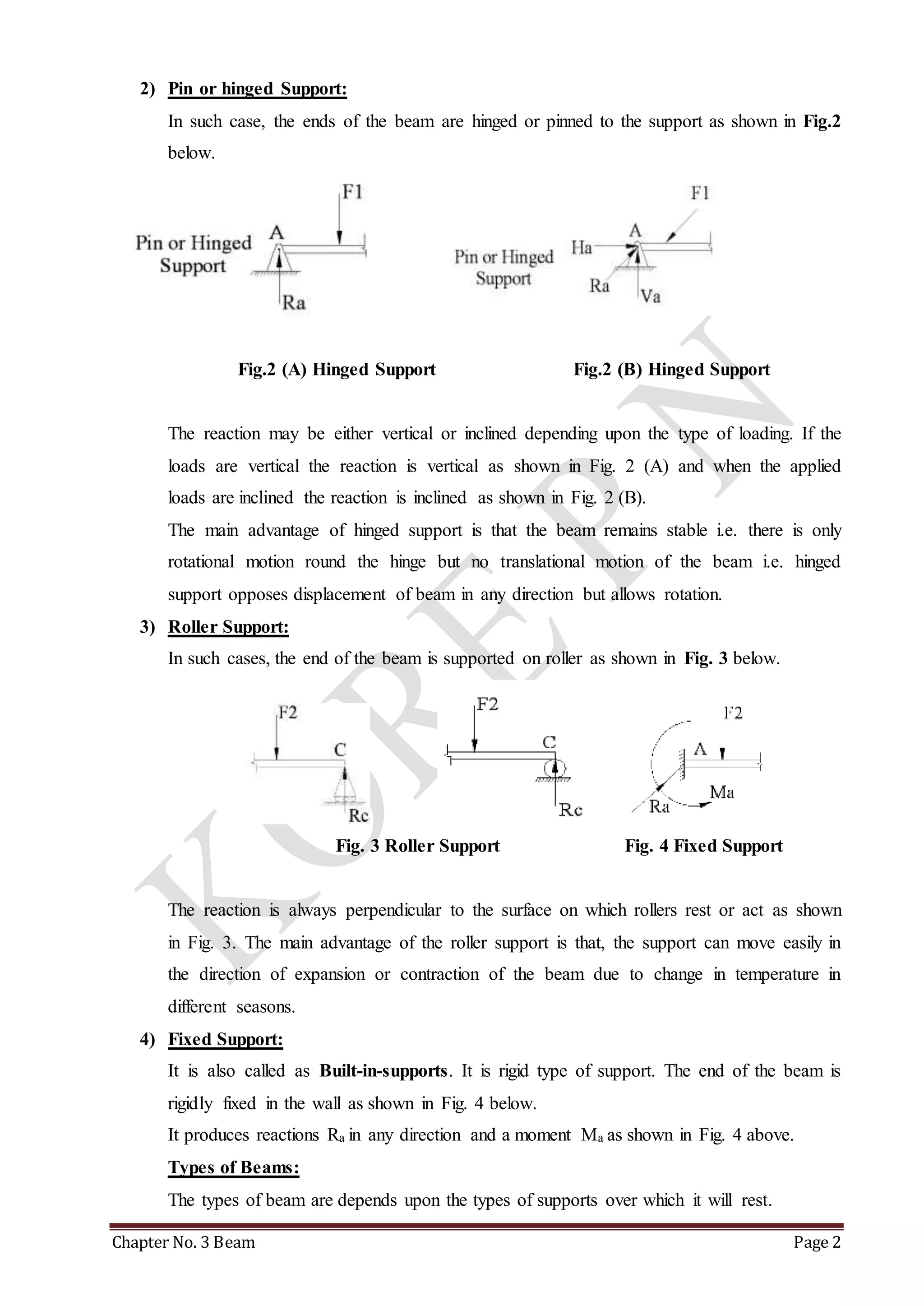
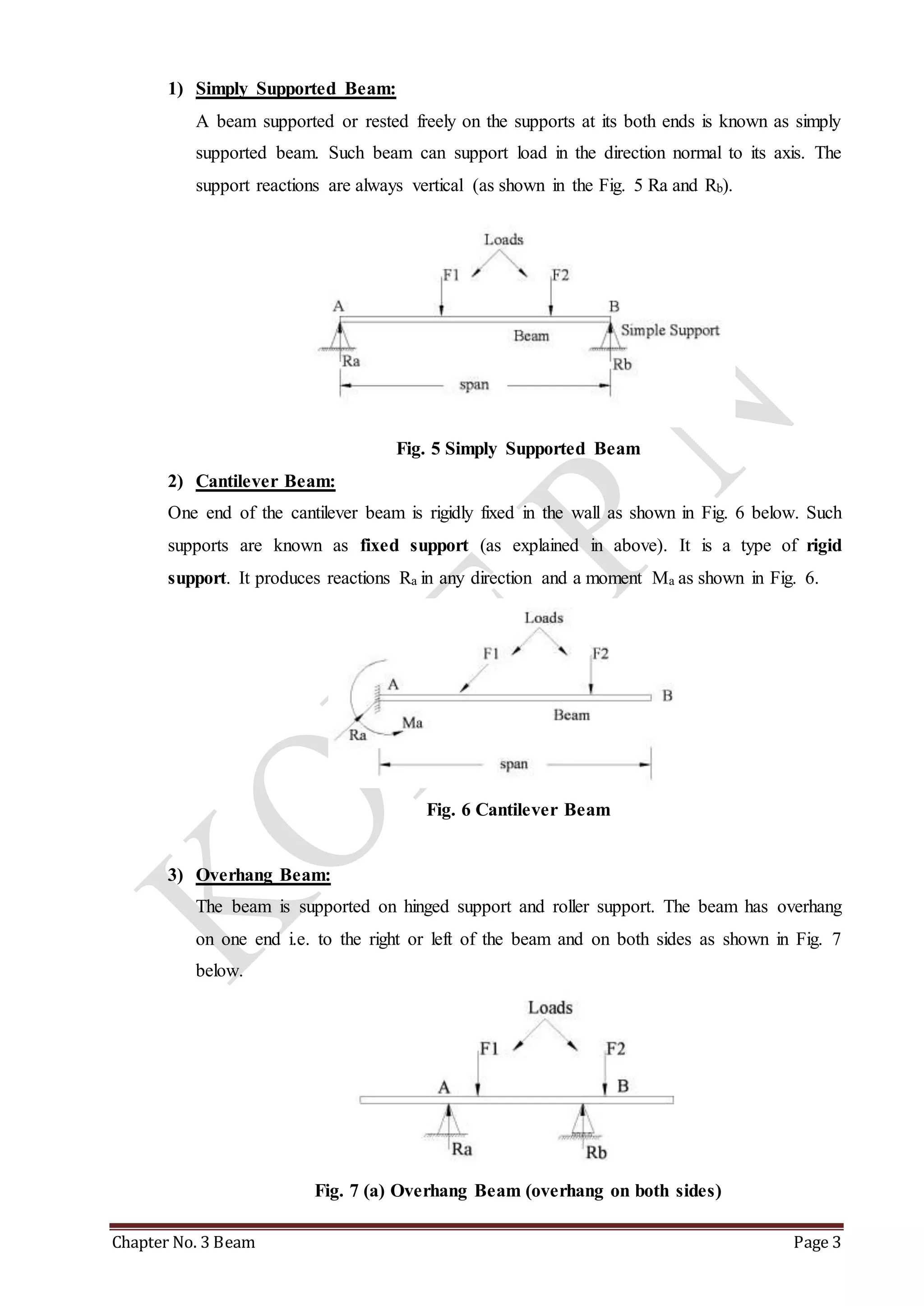
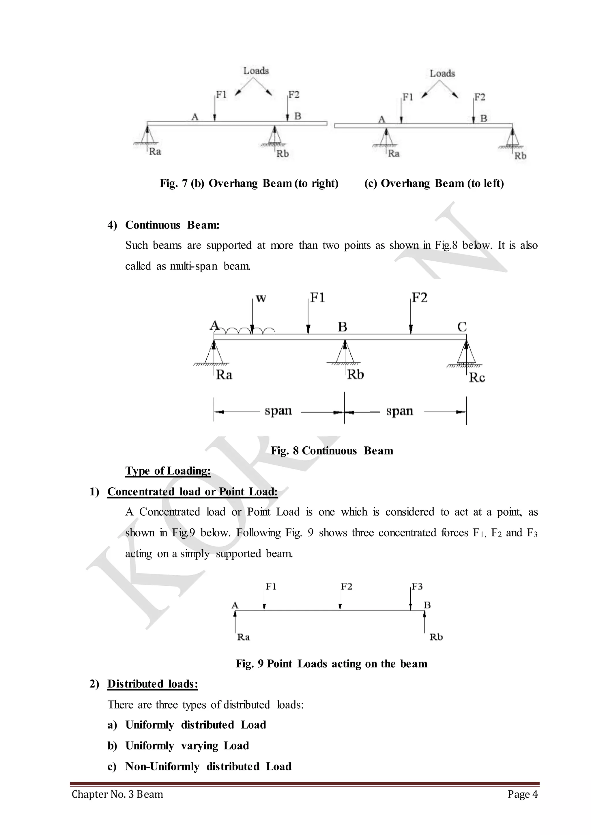
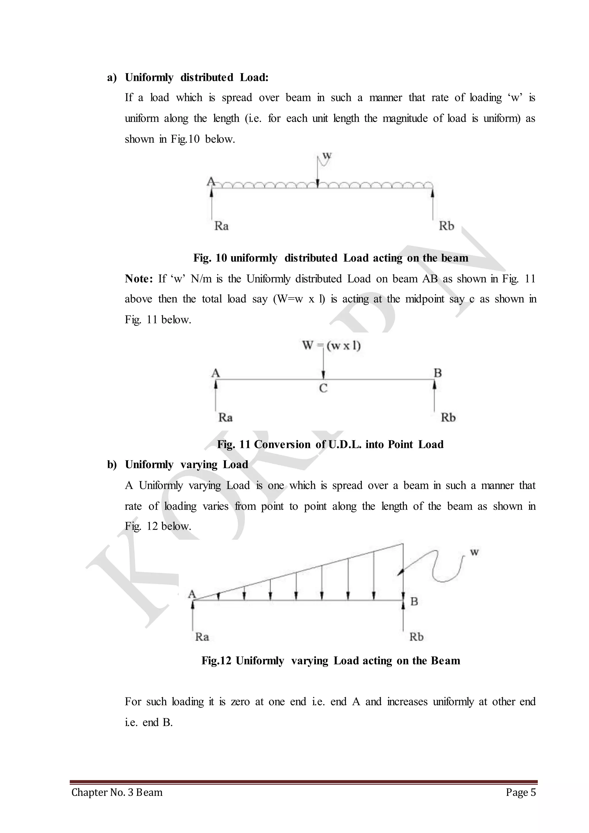
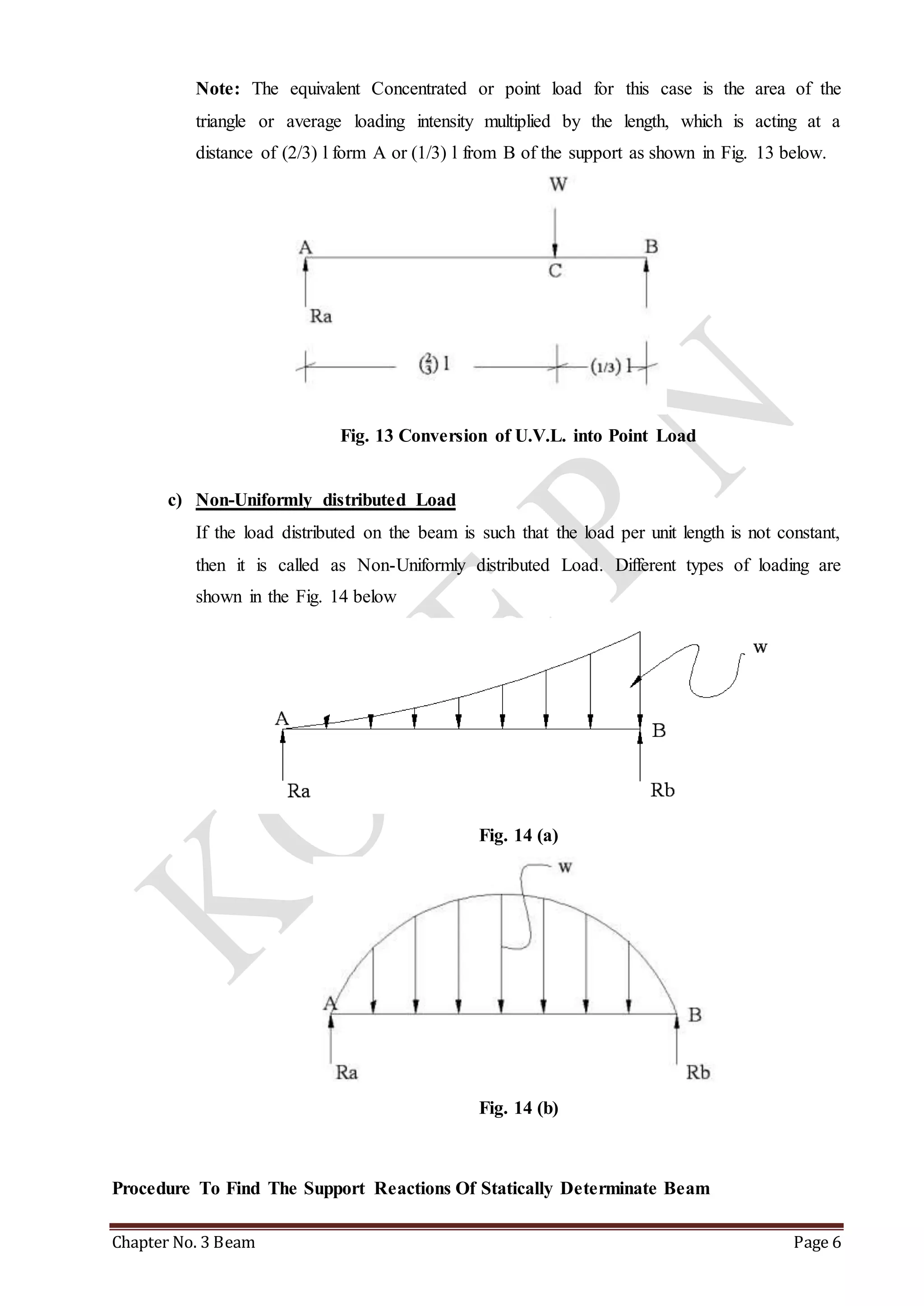
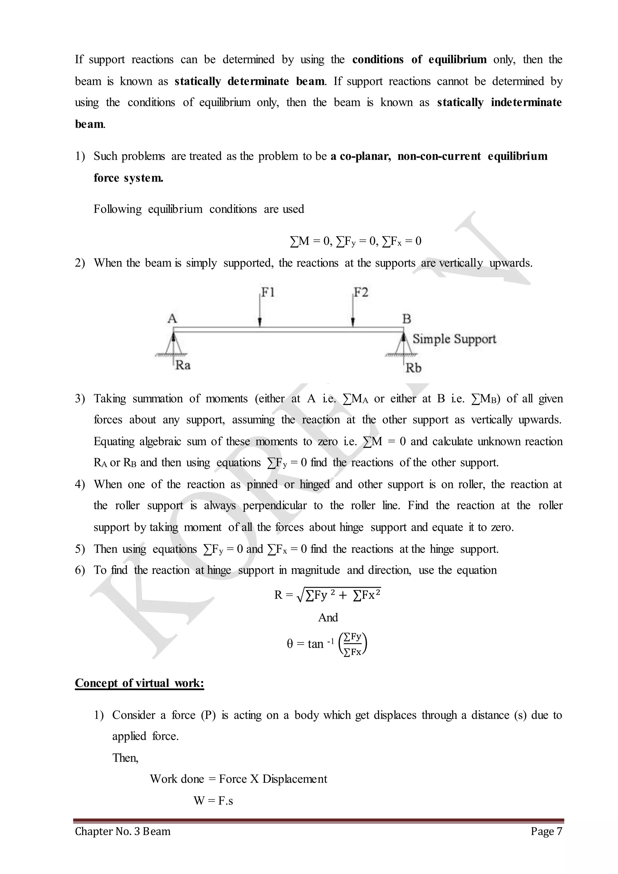
CHAPTER No. 3 
BEAMS AND SUPPORT REACTIONS 
CONTENT OF THE TOPIC: 
- Definition of statically determinate beam 
o Types of beam supports 
o Types of Beams 
o Type of Loading 
- Procedure To Find The Support Reactions Of Statically Determinate Beam 
- Compound beam 
- Concept of virtual work 
Definition of Beam: 
A beam is horizontal or inclined member carrying transverse or inclined loads and supported at 
ends or anywhere. It is a structural member for the frame or structures of steel or concrete which 
has one dimension (length) considerably larger than the other two dimensions. 
If support reactions can be determined by using the conditions of equilibrium only, then the beam 
is known as statically determinate beam. If support reactions cannot be determined by using the 
conditions of equilibrium only, then the beam is known as statically indeterminate beam. 
Definition of span: 
Centre to centre distance between the two end supports is called span. 
Types of beam supports: 
1) Simple support: 
It is a theoretical case in which the ends of the beam are simply supported or rested over 
the supports. The reactions are always vertical as shown in Fig.1 below 
Fig.1 Simple Support 
It opposes downward movement but allows rotation and horizontal displacement or 
movement. 
Chapter No. 3 Beam Page 1
2) Pin or hinged Support: 
In such case, the ends of the beam are hinged or pinned to the support as shown in Fig.2 
below. 
Fig.2 (A) Hinged Support Fig.2 (B) Hinged Support 
The reaction may be either vertical or inclined depending upon the type of loading. If the 
loads are vertical the reaction is vertical as shown in Fig. 2 (A) and when the applied 
loads are inclined the reaction is inclined as shown in Fig. 2 (B). 
The main advantage of hinged support is that the beam remains stable i.e. there is only 
rotational motion round the hinge but no translational motion of the beam i.e. hinged 
support opposes displacement of beam in any direction but allows rotation. 
3) Roller Support: 
In such cases, the end of the beam is supported on roller as shown in Fig. 3 below. 
Fig. 3 Roller Support Fig. 4 Fixed Support 
The reaction is always perpendicular to the surface on which rollers rest or act as shown 
in Fig. 3. The main advantage of the roller support is that, the support can move easily in 
the direction of expansion or contraction of the beam due to change in temperature in 
different seasons. 
4) Fixed Support: 
It is also called as Built-in-supports. It is rigid type of support. The end of the beam is 
rigidly fixed in the wall as shown in Fig. 4 below. 
It produces reactions Ra in any direction and a moment Ma as shown in Fig. 4 above. 
Types of Beams: 
The types of beam are depends upon the types of supports over which it will rest. 
Chapter No. 3 Beam Page 2
1) Simply Supported Beam: 
A beam supported or rested freely on the supports at its both ends is known as simply 
supported beam. Such beam can support load in the direction normal to its axis. The 
support reactions are always vertical (as shown in the Fig. 5 Ra and Rb). 
Fig. 5 Simply Supported Beam 
2) Cantilever Beam: 
One end of the cantilever beam is rigidly fixed in the wall as shown in Fig. 6 below. Such 
supports are known as fixed support (as explained in above). It is a type of rigid 
support. It produces reactions Ra in any direction and a moment Ma as shown in Fig. 6. 
Fig. 6 Cantilever Beam 
3) Overhang Beam: 
The beam is supported on hinged support and roller support. The beam has overhang 
on one end i.e. to the right or left of the beam and on both sides as shown in Fig. 7 
below. 
Fig. 7 (a) Overhang Beam (overhang on both sides) 
Chapter No. 3 Beam Page 3
Fig. 7 (b) Overhang Beam (to right) (c) Overhang Beam (to left) 
4) Continuous Beam: 
Such beams are supported at more than two points as shown in Fig.8 below. It is also 
called as multi-span beam. 
Fig. 8 Continuous Beam 
Type of Loading: 
1) Concentrated load or Point Load: 
A Concentrated load or Point Load is one which is considered to act at a point, as 
shown in Fig.9 below. Following Fig. 9 shows three concentrated forces F1, F2 and F3 
acting on a simply supported beam. 
Fig. 9 Point Loads acting on the beam 
2) Distributed loads: 
There are three types of distributed loads: 
a) Uniformly distributed Load 
b) Uniformly varying Load 
c) Non-Uniformly distributed Load 
Chapter No. 3 Beam Page 4
a) Uniformly distributed Load: 
If a load which is spread over beam in such a manner that rate of loading ‘w’ is 
uniform along the length (i.e. for each unit length the magnitude of load is uniform) as 
shown in Fig.10 below. 
Fig. 10 uniformly distributed Load acting on the beam 
Note: If ‘w’ N/m is the Uniformly distributed Load on beam AB as shown in Fig. 11 
above then the total load say (W=w x l) is acting at the midpoint say c as shown in 
Fig. 11 below. 
Fig. 11 Conversion of U.D.L. into Point Load 
b) Uniformly varying Load 
A Uniformly varying Load is one which is spread over a beam in such a manner that 
rate of loading varies from point to point along the length of the beam as shown in 
Fig. 12 below. 
Fig.12 Uniformly varying Load acting on the Beam 
For such loading it is zero at one end i.e. end A and increases uniformly at other end 
i.e. end B. 
Chapter No. 3 Beam Page 5
Note: The equivalent Concentrated or point load for this case is the area of the 
triangle or average loading intensity multiplied by the length, which is acting at a 
distance of (2/3) l form A or (1/3) l from B of the support as shown in Fig. 13 below. 
Fig. 13 Conversion of U.V.L. into Point Load 
c) Non-Uniformly distributed Load 
If the load distributed on the beam is such that the load per unit length is not constant, 
then it is called as Non-Uniformly distributed Load. Different types of loading are 
shown in the Fig. 14 below 
Fig. 14 (a) 
Fig. 14 (b) 
Procedure To Find The Support Reactions Of Statically Determinate Beam 
Chapter No. 3 Beam Page 6
If support reactions can be determined by using the conditions of equilibrium only, then the 
beam is known as statically determinate beam. If support reactions cannot be determined by 
using the conditions of equilibrium only, then the beam is known as statically indeterminate 
beam. 
1) Such problems are treated as the problem to be a co-planar, non-con-current equilibrium 
force system. 
Following equilibrium conditions are used 
ΣM = 0, ΣFy = 0, ΣFx = 0 
2) When the beam is simply supported, the reactions at the supports are vertically upwards. 
3) Taking summation of moments (either at A i.e. ΣMA or either at B i.e. ΣMB) of all given 
forces about any support, assuming the reaction at the other support as vertically upwards. 
Equating algebraic sum of these moments to zero i.e. ΣM = 0 and calculate unknown reaction 
RA or RB and then using equations ΣFy = 0 find the reactions of the other support. 
4) When one of the reaction as pinned or hinged and other support is on roller, the reaction at 
the roller support is always perpendicular to the roller line. Find the reaction at the roller 
support by taking moment of all the forces about hinge support and equate it to zero. 
5) Then using equations ΣFy = 0 and ΣFx = 0 find the reactions at the hinge support. 
6) To find the reaction at hinge support in magnitude and direction, use the equation 
R = √ΣFy 2 + ΣFx2 
And 
ΣFy 
ΣFx 
θ = tan -1 ( 
) 
Concept of virtual work: 
1) Consider a force (P) is acting on a body which get displaces through a distance (s) due to 
applied force. 
Then, 
Work done = Force X Displacement 
W = F.s 
Chapter No. 3 Beam Page 7
2) But if the body is in equilibrium, under the action of a system of forces, then the work 
done is zero. 
3) If we assume that the body, which is in equilibrium, undergoes a small imaginary 
displacement (virtual displacement) some work will be imagined to be done. Such 
imaginary work is called as virtual work. This concept is useful to find out the unknown 
forces in the structures. 
Principle of virtual work: 
“ If system of forces acting on a body (or a system of bodies) be in equilibrium and the system to 
be imagined to undergo a small displacement consistent with the geometrical conditions, then the 
algebraic sum of the virtual works done by all the system is zero”. 
i.e. mathematically, 
ΣW = 0 
Types of virtual work: 
1) Linear virtual work: 
If a force (F) causes a displacement (virtual displacement) in its direction of line of 
action, then its virtual work is given as,  
WV = F x δ 
Sign convention: 
Upward forces are considered as positive, while downward forces are considered as 
negative 
QUESIONS 
1. What are the different types of beam support? Explain the reactions exerted by each type 
of support.(4 Mks) or 
2. What are the different types of supports? Indicate with neat sketch of reactions offered by 
them. 
3. Explain the concept of virtual work? (3 Mks) 
Chapter No. 3 Beam Page 8

Chapter 2 beam

  • 1.
    CHAPTER No. 3 BEAMS AND SUPPORT REACTIONS CONTENT OF THE TOPIC: - Definition of statically determinate beam o Types of beam supports o Types of Beams o Type of Loading - Procedure To Find The Support Reactions Of Statically Determinate Beam - Compound beam - Concept of virtual work Definition of Beam: A beam is horizontal or inclined member carrying transverse or inclined loads and supported at ends or anywhere. It is a structural member for the frame or structures of steel or concrete which has one dimension (length) considerably larger than the other two dimensions. If support reactions can be determined by using the conditions of equilibrium only, then the beam is known as statically determinate beam. If support reactions cannot be determined by using the conditions of equilibrium only, then the beam is known as statically indeterminate beam. Definition of span: Centre to centre distance between the two end supports is called span. Types of beam supports: 1) Simple support: It is a theoretical case in which the ends of the beam are simply supported or rested over the supports. The reactions are always vertical as shown in Fig.1 below Fig.1 Simple Support It opposes downward movement but allows rotation and horizontal displacement or movement. Chapter No. 3 Beam Page 1
  • 2.
    2) Pin orhinged Support: In such case, the ends of the beam are hinged or pinned to the support as shown in Fig.2 below. Fig.2 (A) Hinged Support Fig.2 (B) Hinged Support The reaction may be either vertical or inclined depending upon the type of loading. If the loads are vertical the reaction is vertical as shown in Fig. 2 (A) and when the applied loads are inclined the reaction is inclined as shown in Fig. 2 (B). The main advantage of hinged support is that the beam remains stable i.e. there is only rotational motion round the hinge but no translational motion of the beam i.e. hinged support opposes displacement of beam in any direction but allows rotation. 3) Roller Support: In such cases, the end of the beam is supported on roller as shown in Fig. 3 below. Fig. 3 Roller Support Fig. 4 Fixed Support The reaction is always perpendicular to the surface on which rollers rest or act as shown in Fig. 3. The main advantage of the roller support is that, the support can move easily in the direction of expansion or contraction of the beam due to change in temperature in different seasons. 4) Fixed Support: It is also called as Built-in-supports. It is rigid type of support. The end of the beam is rigidly fixed in the wall as shown in Fig. 4 below. It produces reactions Ra in any direction and a moment Ma as shown in Fig. 4 above. Types of Beams: The types of beam are depends upon the types of supports over which it will rest. Chapter No. 3 Beam Page 2
  • 3.
    1) Simply SupportedBeam: A beam supported or rested freely on the supports at its both ends is known as simply supported beam. Such beam can support load in the direction normal to its axis. The support reactions are always vertical (as shown in the Fig. 5 Ra and Rb). Fig. 5 Simply Supported Beam 2) Cantilever Beam: One end of the cantilever beam is rigidly fixed in the wall as shown in Fig. 6 below. Such supports are known as fixed support (as explained in above). It is a type of rigid support. It produces reactions Ra in any direction and a moment Ma as shown in Fig. 6. Fig. 6 Cantilever Beam 3) Overhang Beam: The beam is supported on hinged support and roller support. The beam has overhang on one end i.e. to the right or left of the beam and on both sides as shown in Fig. 7 below. Fig. 7 (a) Overhang Beam (overhang on both sides) Chapter No. 3 Beam Page 3
  • 4.
    Fig. 7 (b)Overhang Beam (to right) (c) Overhang Beam (to left) 4) Continuous Beam: Such beams are supported at more than two points as shown in Fig.8 below. It is also called as multi-span beam. Fig. 8 Continuous Beam Type of Loading: 1) Concentrated load or Point Load: A Concentrated load or Point Load is one which is considered to act at a point, as shown in Fig.9 below. Following Fig. 9 shows three concentrated forces F1, F2 and F3 acting on a simply supported beam. Fig. 9 Point Loads acting on the beam 2) Distributed loads: There are three types of distributed loads: a) Uniformly distributed Load b) Uniformly varying Load c) Non-Uniformly distributed Load Chapter No. 3 Beam Page 4
  • 5.
    a) Uniformly distributedLoad: If a load which is spread over beam in such a manner that rate of loading ‘w’ is uniform along the length (i.e. for each unit length the magnitude of load is uniform) as shown in Fig.10 below. Fig. 10 uniformly distributed Load acting on the beam Note: If ‘w’ N/m is the Uniformly distributed Load on beam AB as shown in Fig. 11 above then the total load say (W=w x l) is acting at the midpoint say c as shown in Fig. 11 below. Fig. 11 Conversion of U.D.L. into Point Load b) Uniformly varying Load A Uniformly varying Load is one which is spread over a beam in such a manner that rate of loading varies from point to point along the length of the beam as shown in Fig. 12 below. Fig.12 Uniformly varying Load acting on the Beam For such loading it is zero at one end i.e. end A and increases uniformly at other end i.e. end B. Chapter No. 3 Beam Page 5
  • 6.
    Note: The equivalentConcentrated or point load for this case is the area of the triangle or average loading intensity multiplied by the length, which is acting at a distance of (2/3) l form A or (1/3) l from B of the support as shown in Fig. 13 below. Fig. 13 Conversion of U.V.L. into Point Load c) Non-Uniformly distributed Load If the load distributed on the beam is such that the load per unit length is not constant, then it is called as Non-Uniformly distributed Load. Different types of loading are shown in the Fig. 14 below Fig. 14 (a) Fig. 14 (b) Procedure To Find The Support Reactions Of Statically Determinate Beam Chapter No. 3 Beam Page 6
  • 7.
    If support reactionscan be determined by using the conditions of equilibrium only, then the beam is known as statically determinate beam. If support reactions cannot be determined by using the conditions of equilibrium only, then the beam is known as statically indeterminate beam. 1) Such problems are treated as the problem to be a co-planar, non-con-current equilibrium force system. Following equilibrium conditions are used ΣM = 0, ΣFy = 0, ΣFx = 0 2) When the beam is simply supported, the reactions at the supports are vertically upwards. 3) Taking summation of moments (either at A i.e. ΣMA or either at B i.e. ΣMB) of all given forces about any support, assuming the reaction at the other support as vertically upwards. Equating algebraic sum of these moments to zero i.e. ΣM = 0 and calculate unknown reaction RA or RB and then using equations ΣFy = 0 find the reactions of the other support. 4) When one of the reaction as pinned or hinged and other support is on roller, the reaction at the roller support is always perpendicular to the roller line. Find the reaction at the roller support by taking moment of all the forces about hinge support and equate it to zero. 5) Then using equations ΣFy = 0 and ΣFx = 0 find the reactions at the hinge support. 6) To find the reaction at hinge support in magnitude and direction, use the equation R = √ΣFy 2 + ΣFx2 And ΣFy ΣFx θ = tan -1 ( ) Concept of virtual work: 1) Consider a force (P) is acting on a body which get displaces through a distance (s) due to applied force. Then, Work done = Force X Displacement W = F.s Chapter No. 3 Beam Page 7
  • 8.
    2) But ifthe body is in equilibrium, under the action of a system of forces, then the work done is zero. 3) If we assume that the body, which is in equilibrium, undergoes a small imaginary displacement (virtual displacement) some work will be imagined to be done. Such imaginary work is called as virtual work. This concept is useful to find out the unknown forces in the structures. Principle of virtual work: “ If system of forces acting on a body (or a system of bodies) be in equilibrium and the system to be imagined to undergo a small displacement consistent with the geometrical conditions, then the algebraic sum of the virtual works done by all the system is zero”. i.e. mathematically, ΣW = 0 Types of virtual work: 1) Linear virtual work: If a force (F) causes a displacement (virtual displacement) in its direction of line of action, then its virtual work is given as, WV = F x δ Sign convention: Upward forces are considered as positive, while downward forces are considered as negative QUESIONS 1. What are the different types of beam support? Explain the reactions exerted by each type of support.(4 Mks) or 2. What are the different types of supports? Indicate with neat sketch of reactions offered by them. 3. Explain the concept of virtual work? (3 Mks) Chapter No. 3 Beam Page 8