The document summarizes key concepts in the theory of structures including:
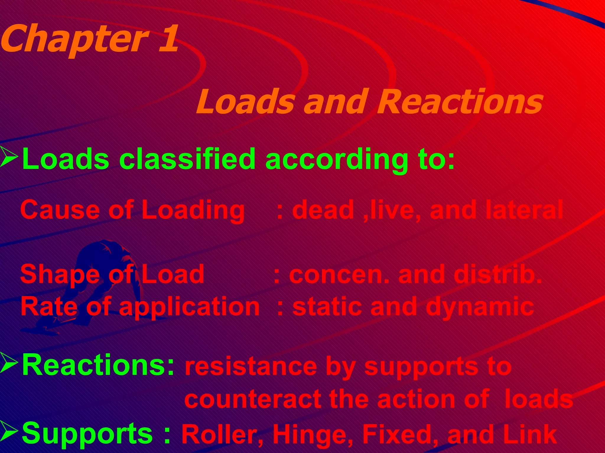
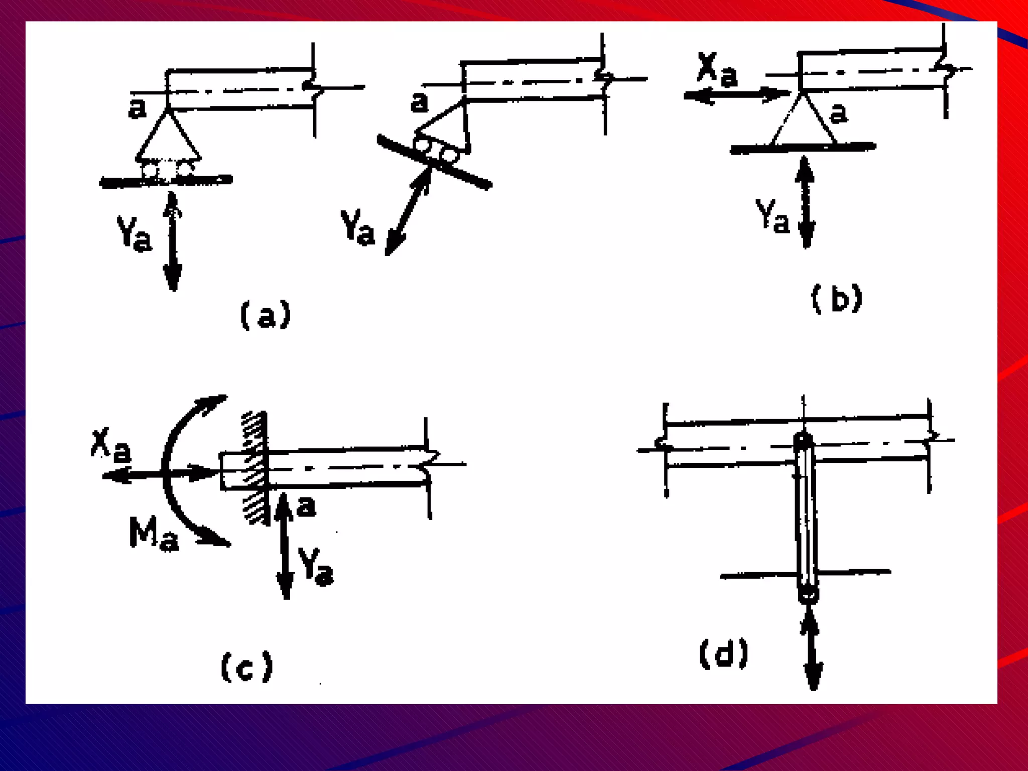
- Types of loads, reactions, and supports
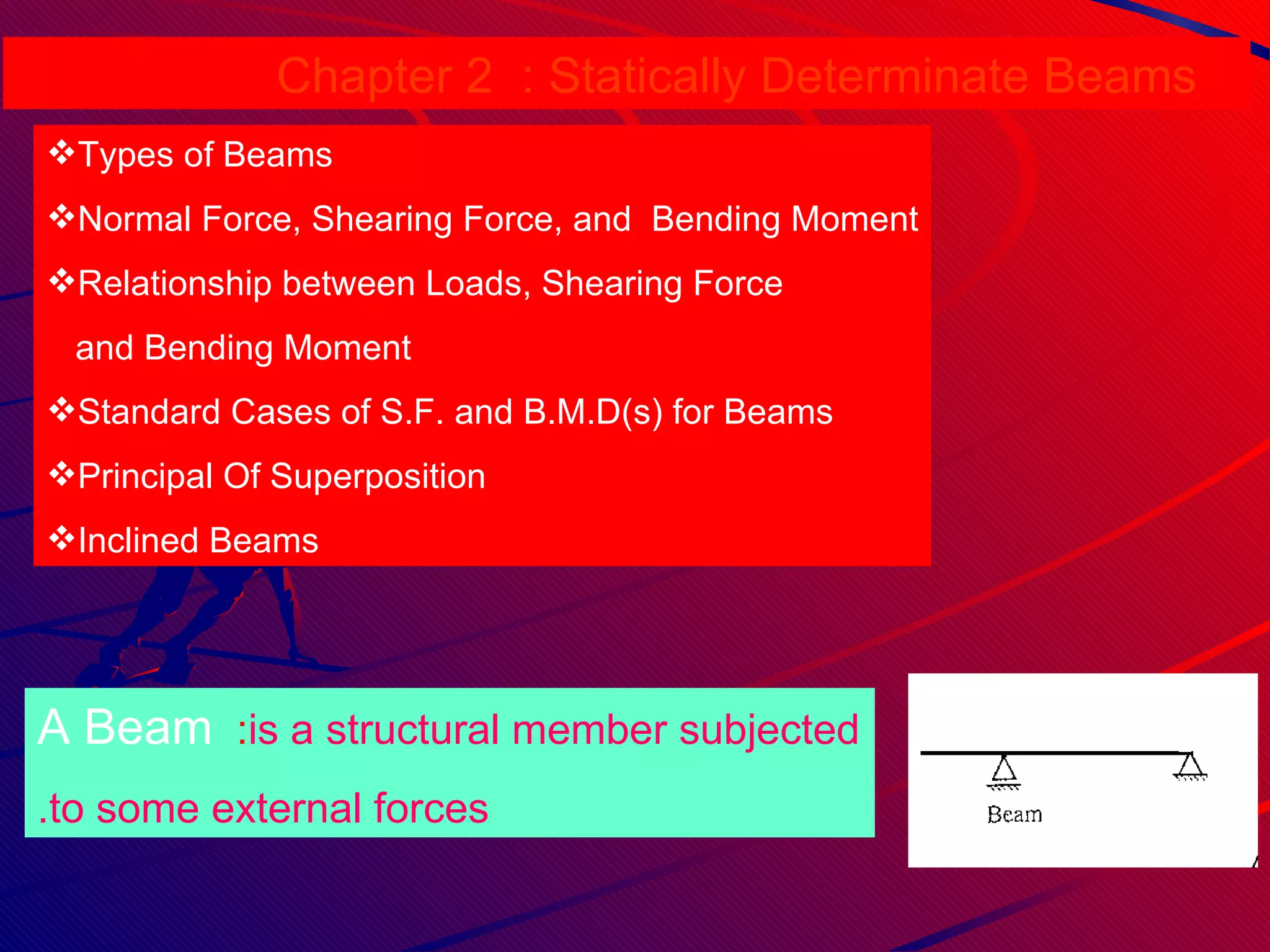
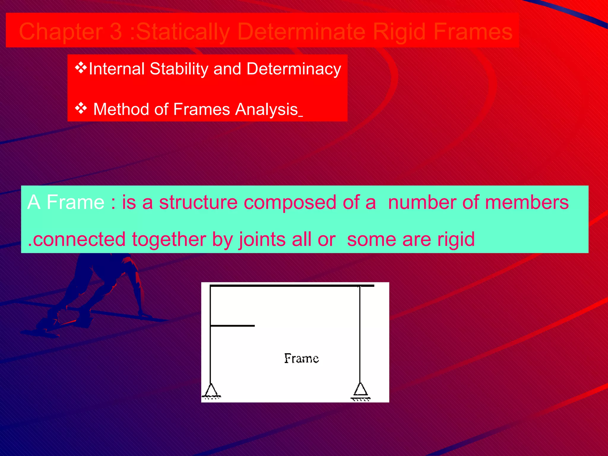
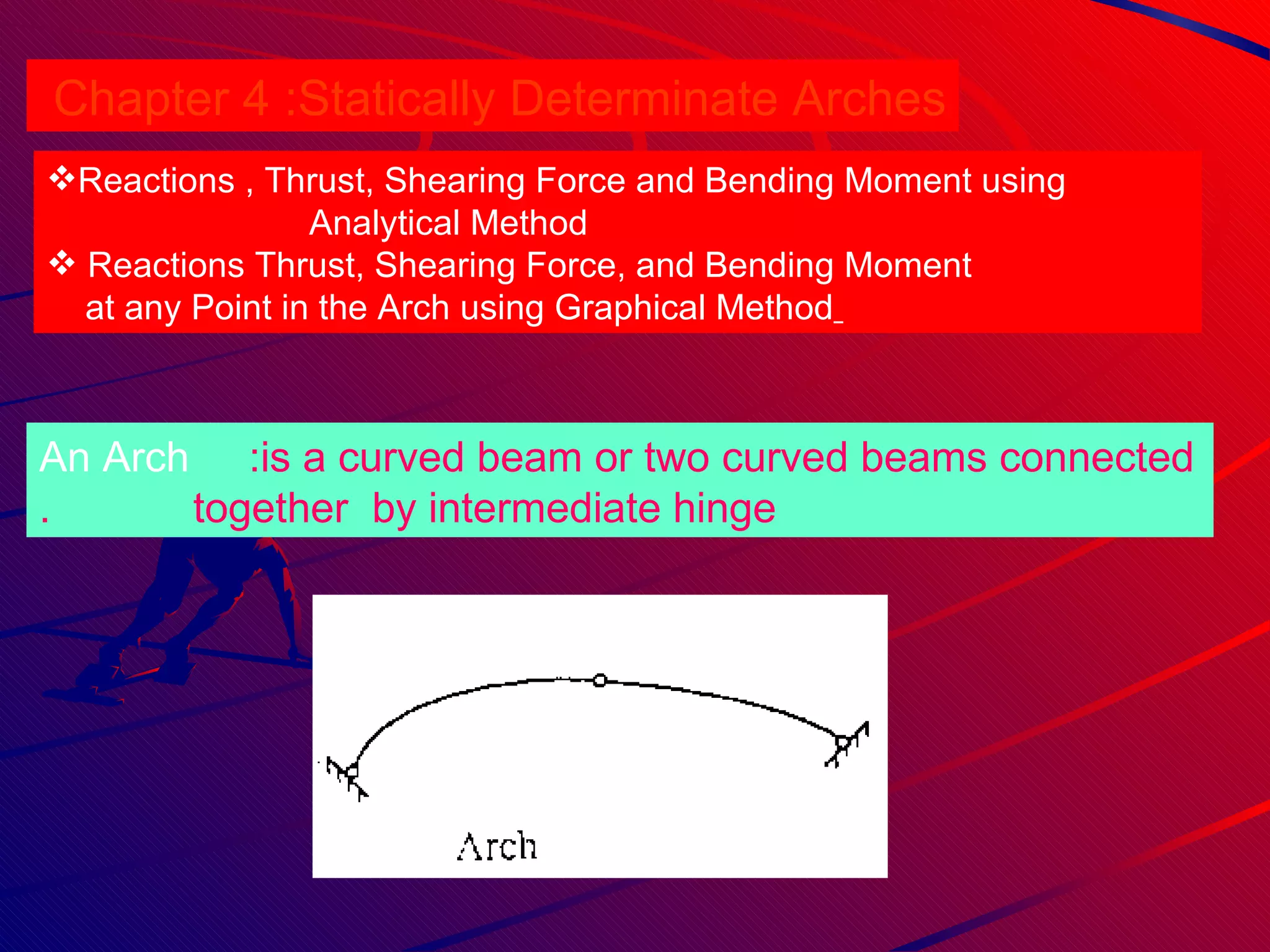
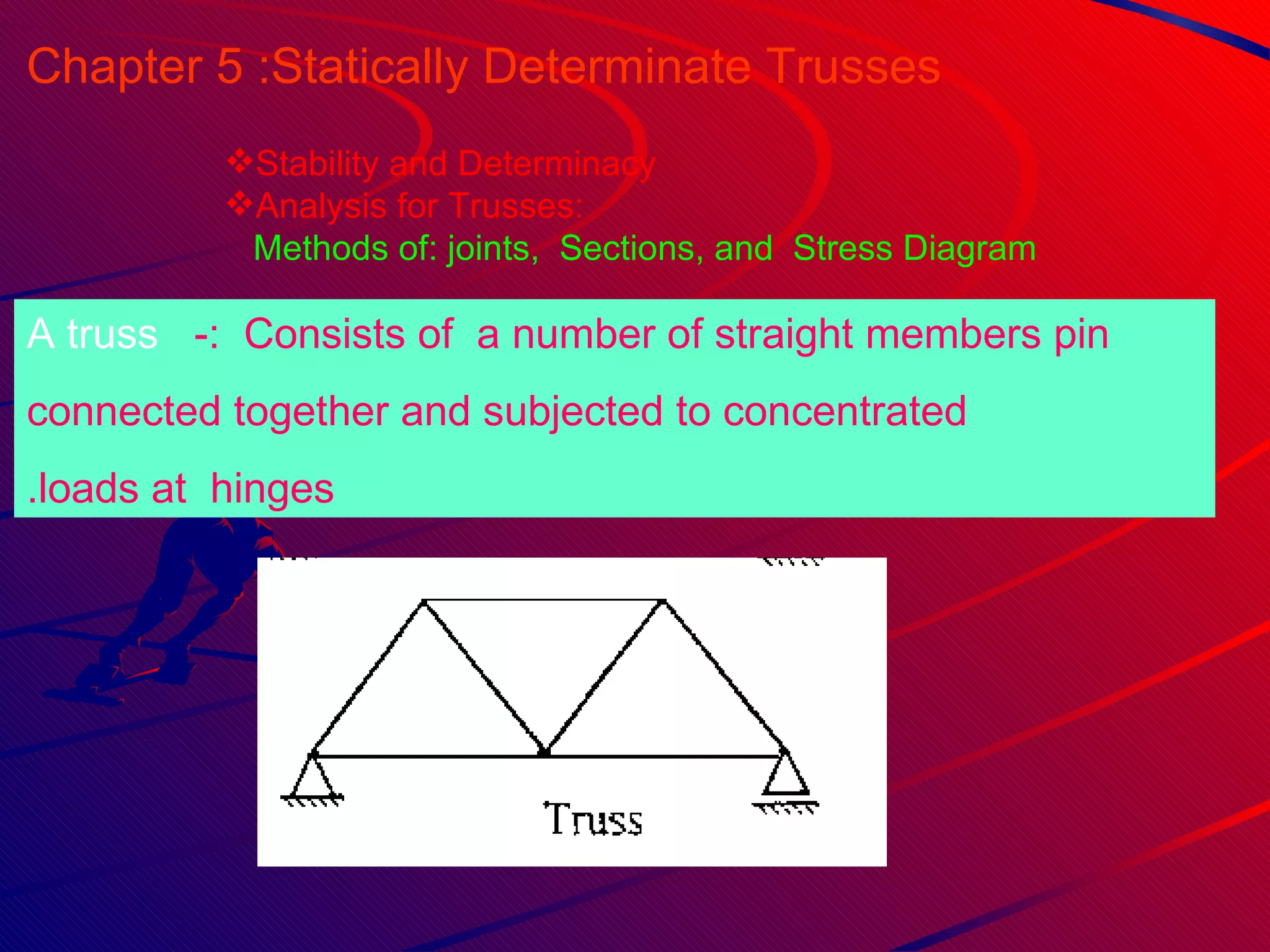
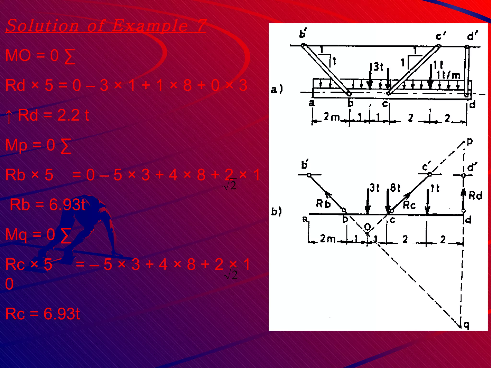
- Statically determinate beams, frames, arches, and trusses
- Relationship between loads, shear forces, and bending moments
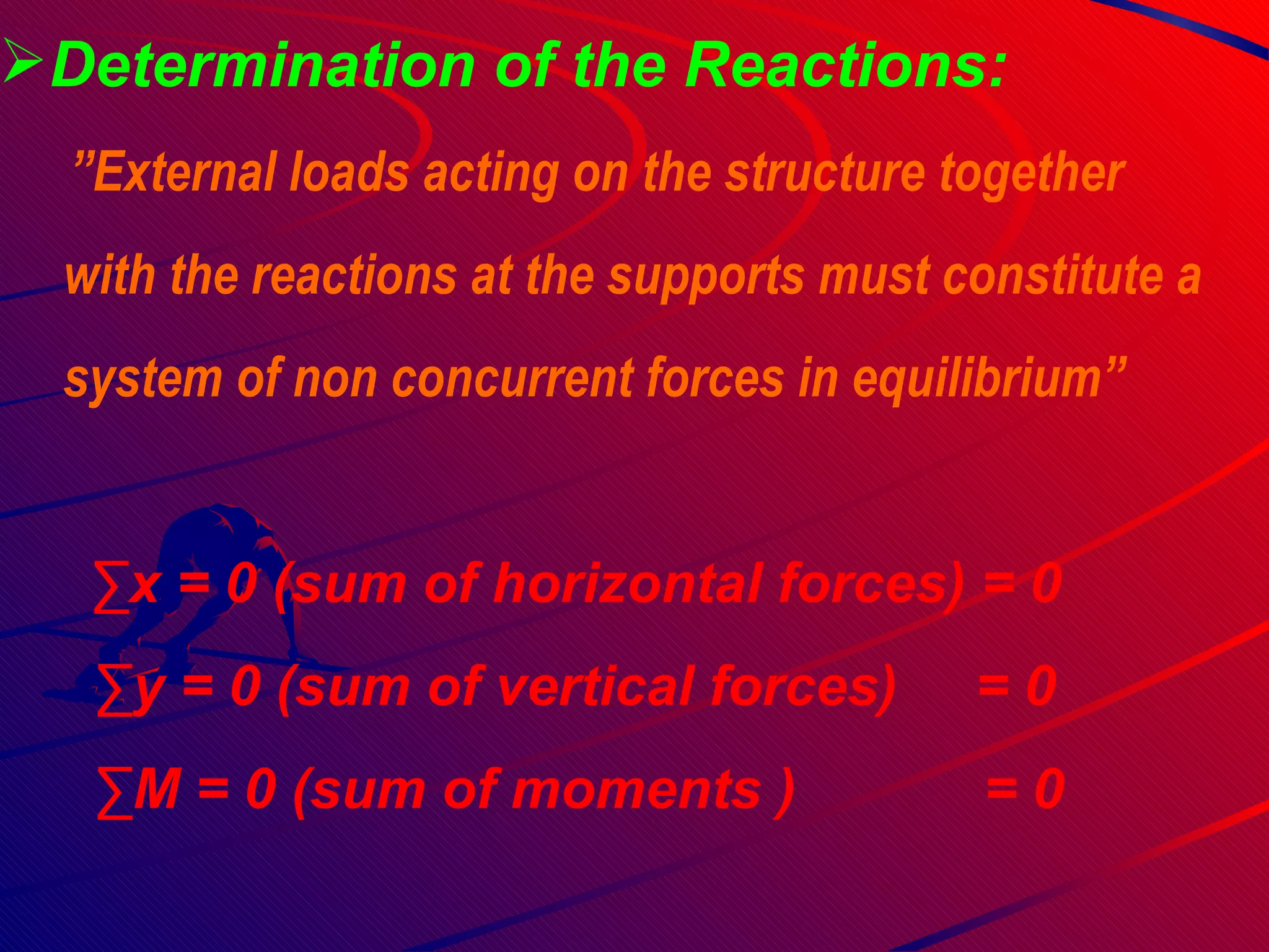
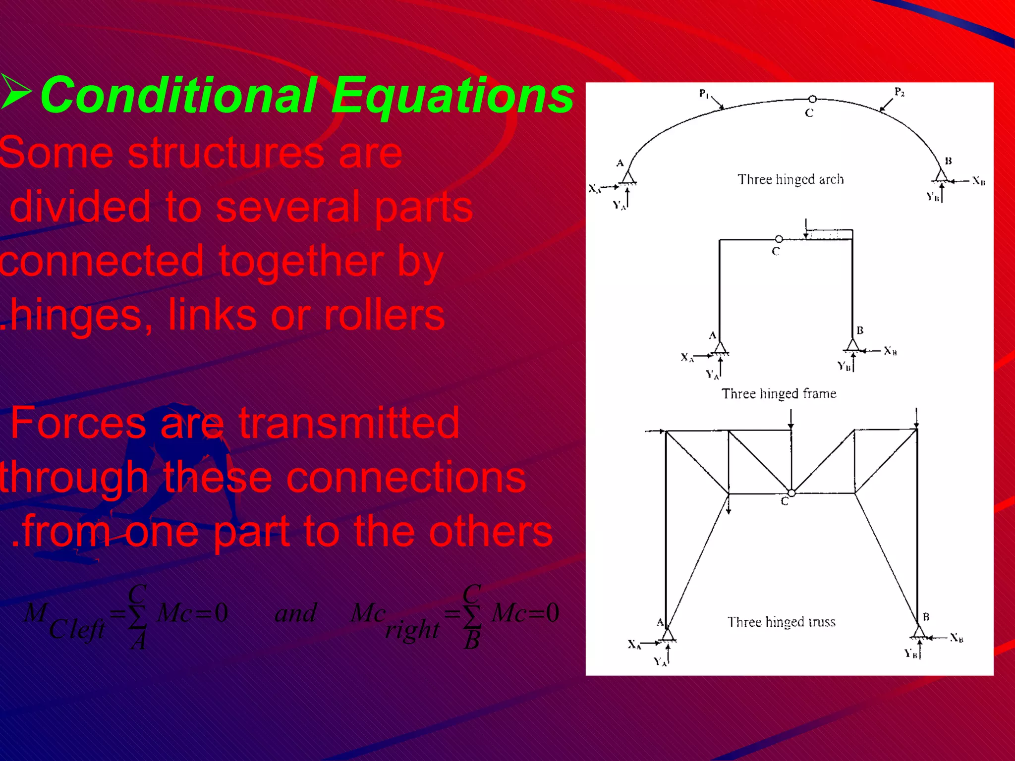
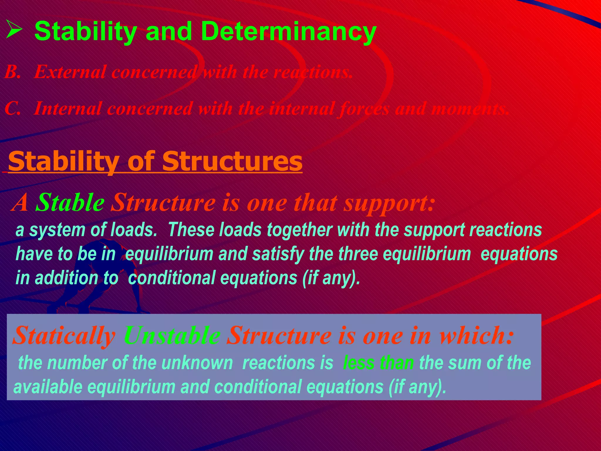
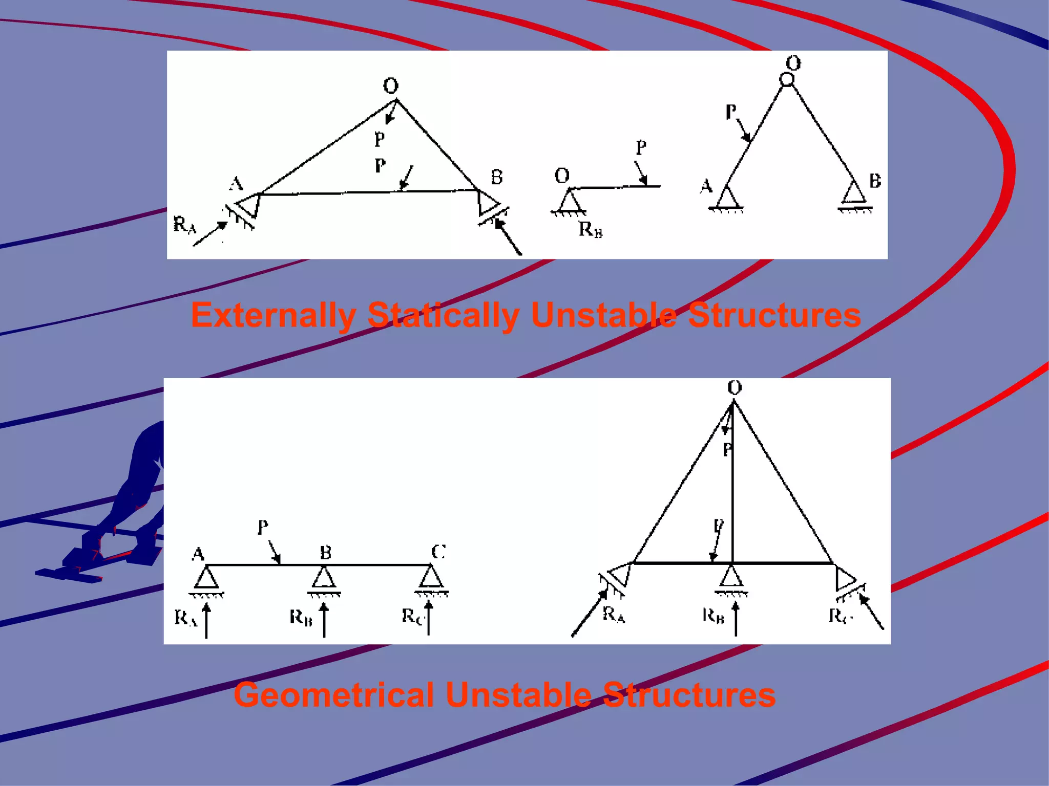
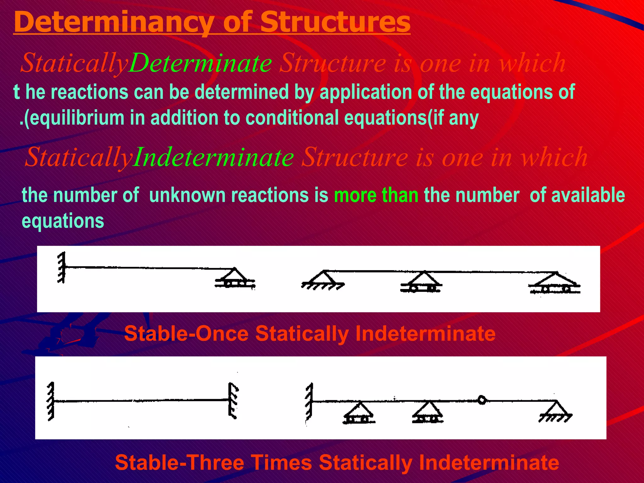
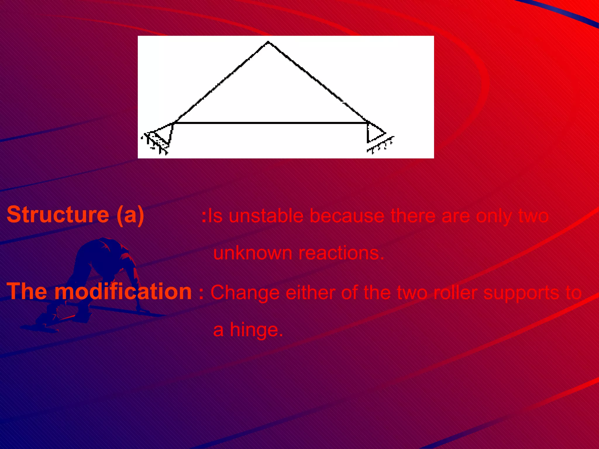
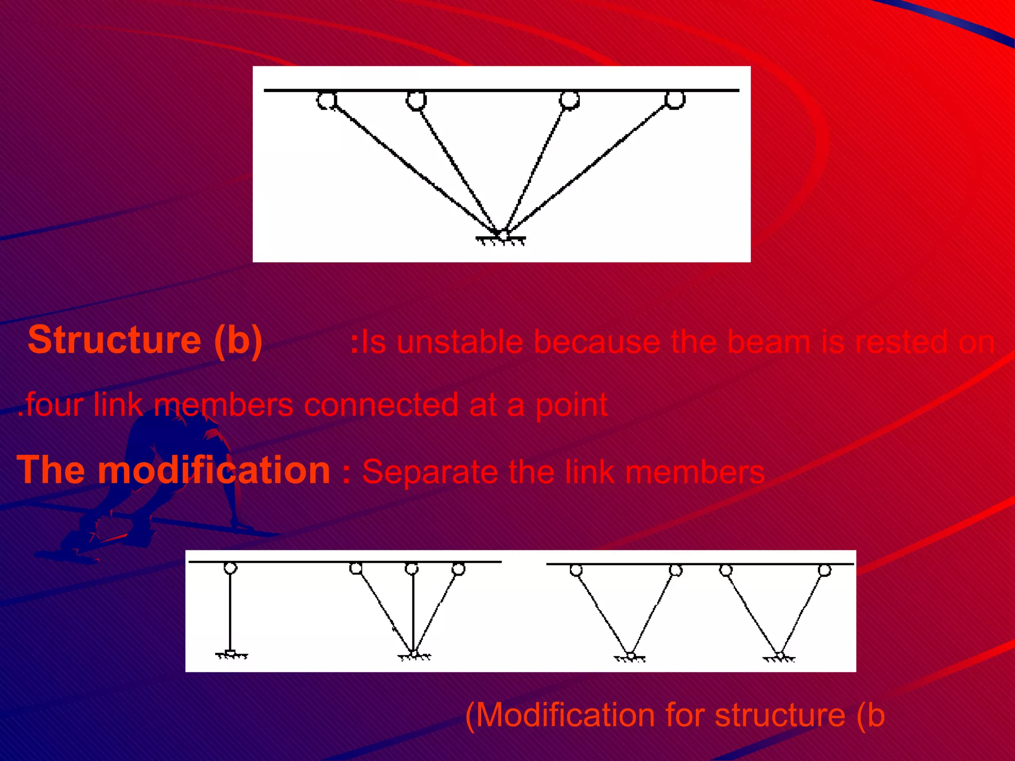
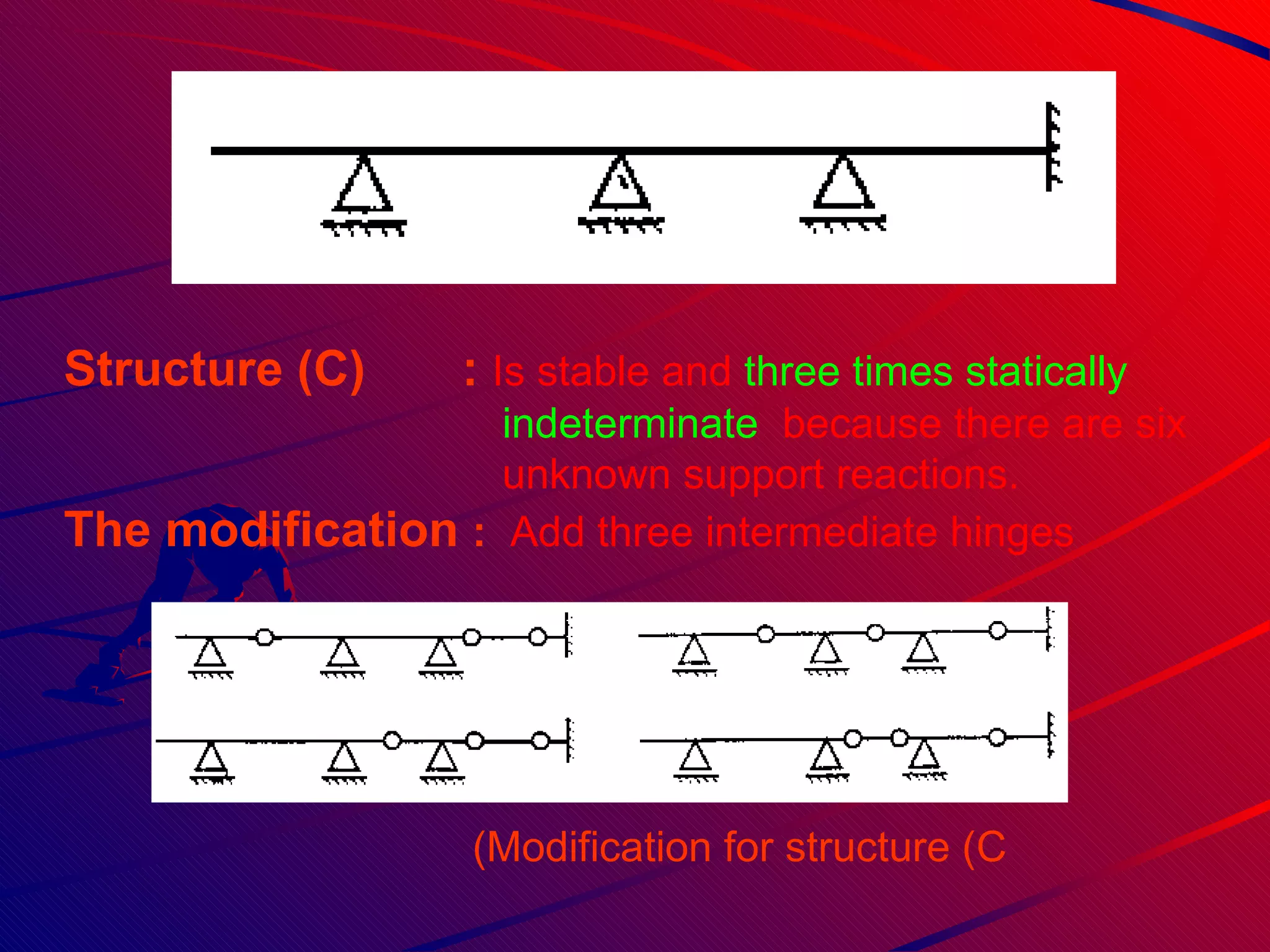
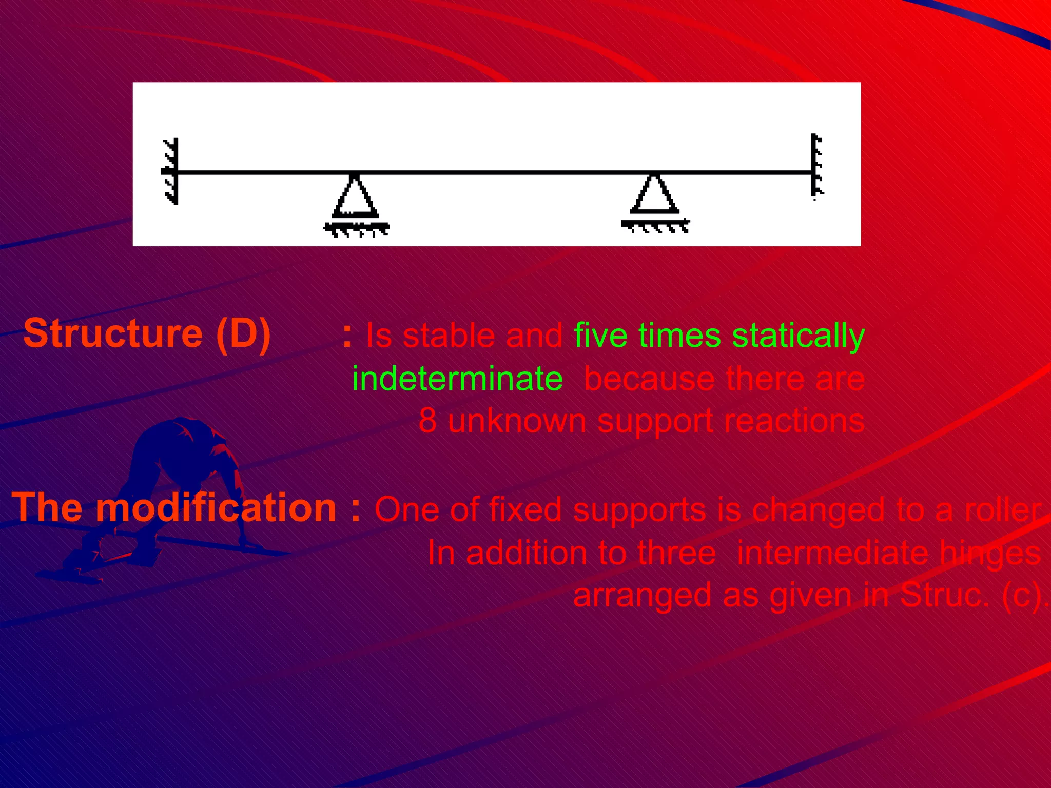
- Concepts of stability, determinacy, and methods of analysis for solving equilibrium and conditional equations
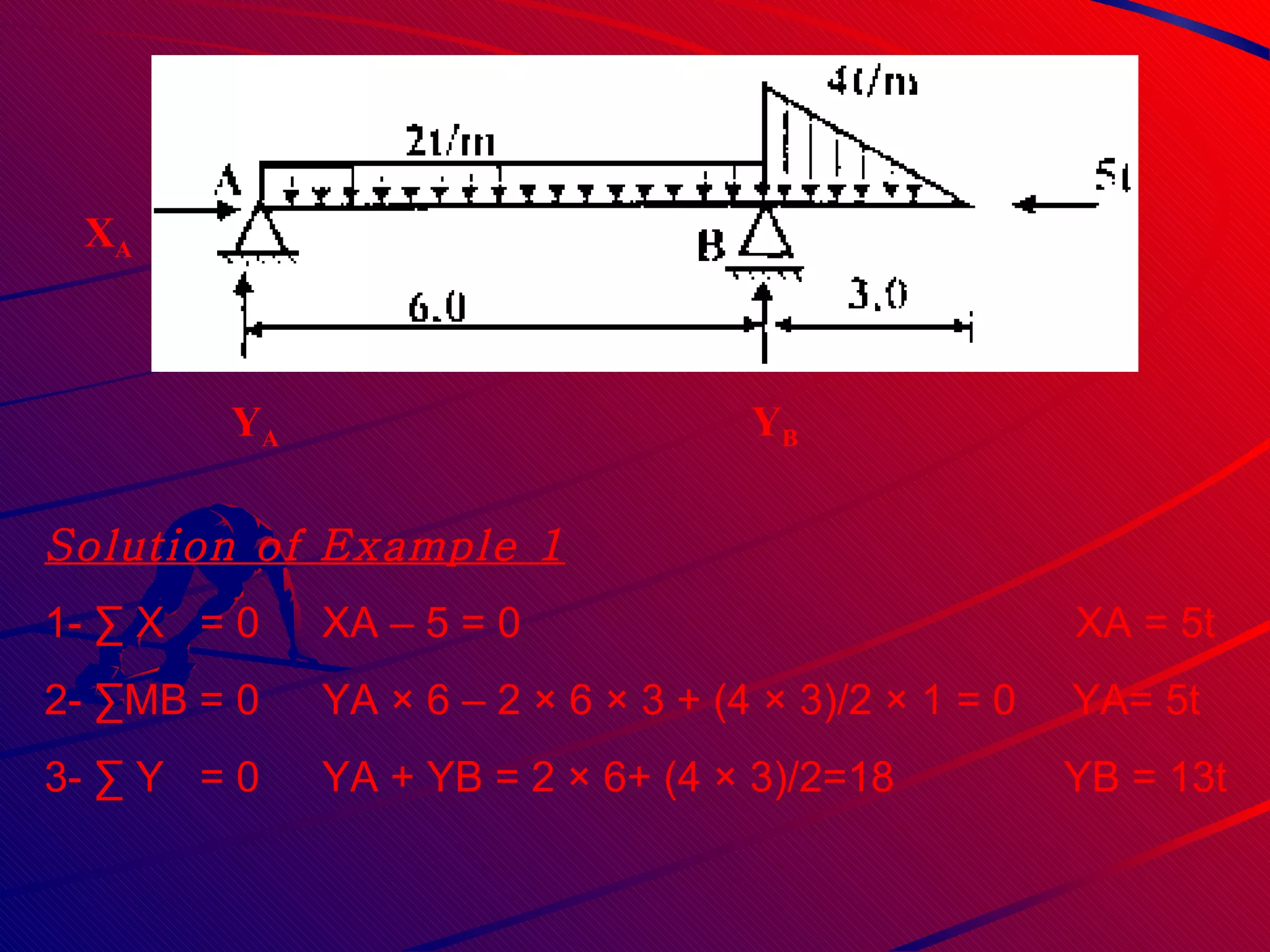
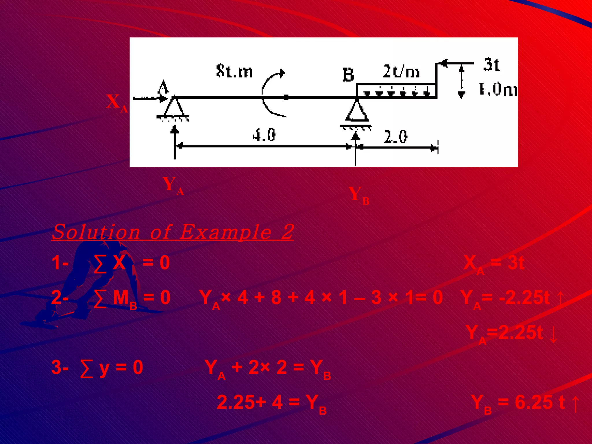
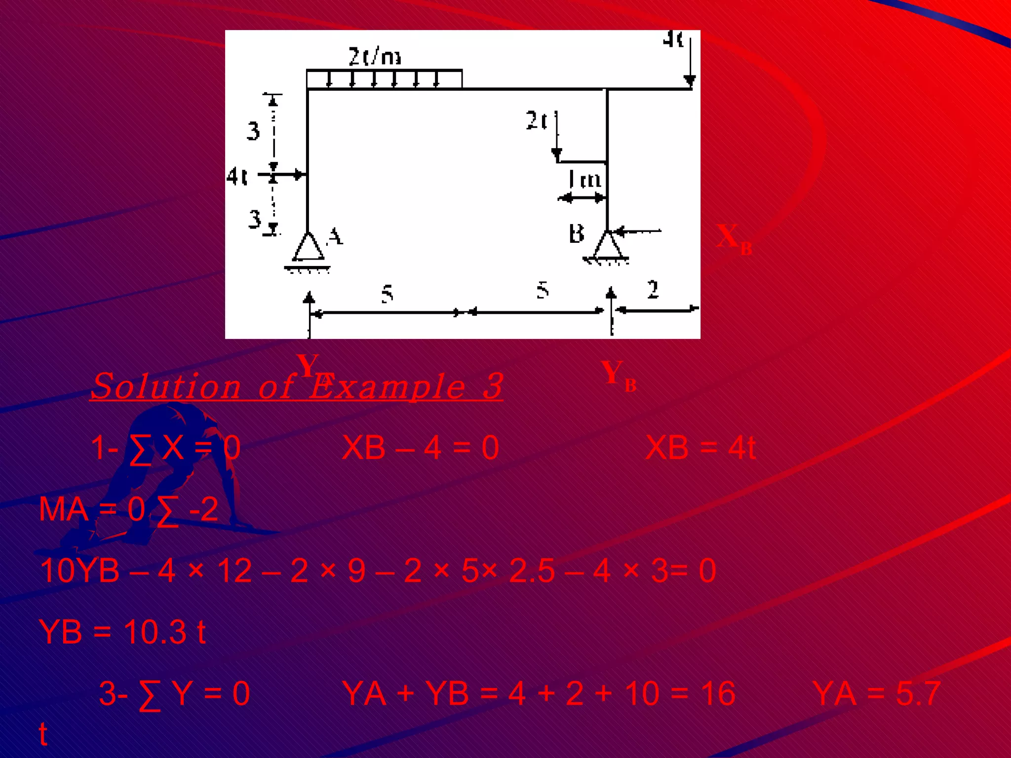
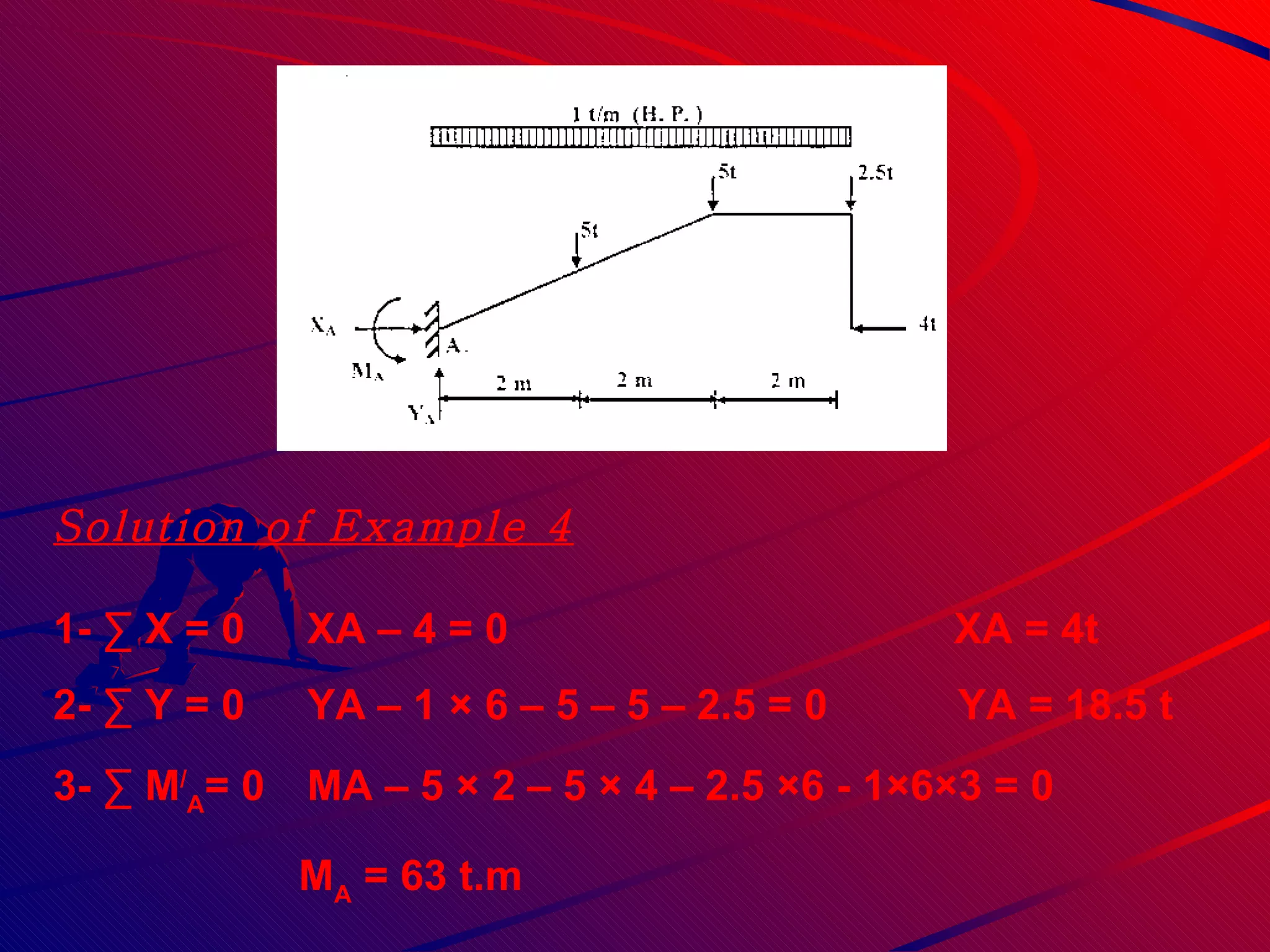
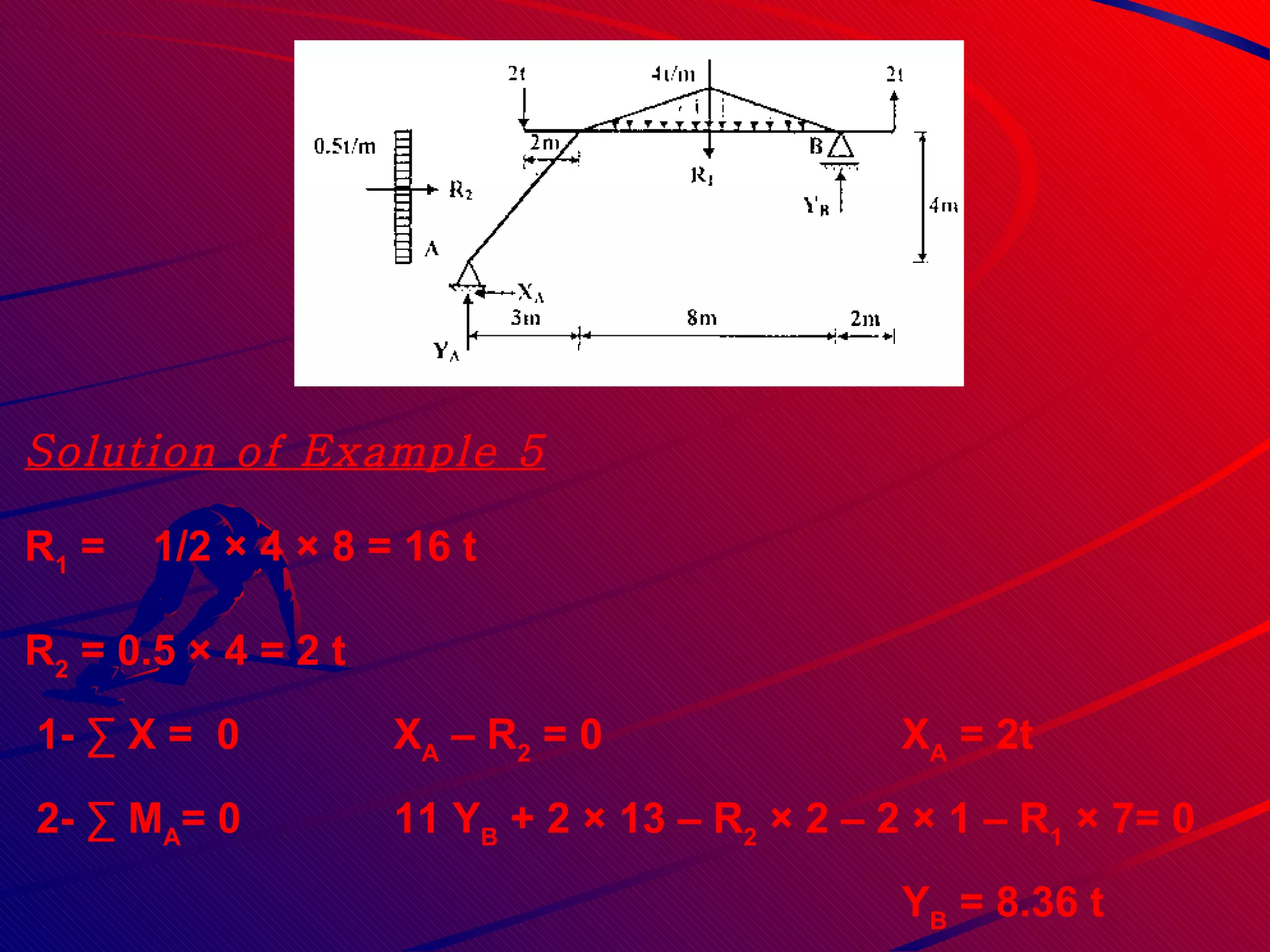
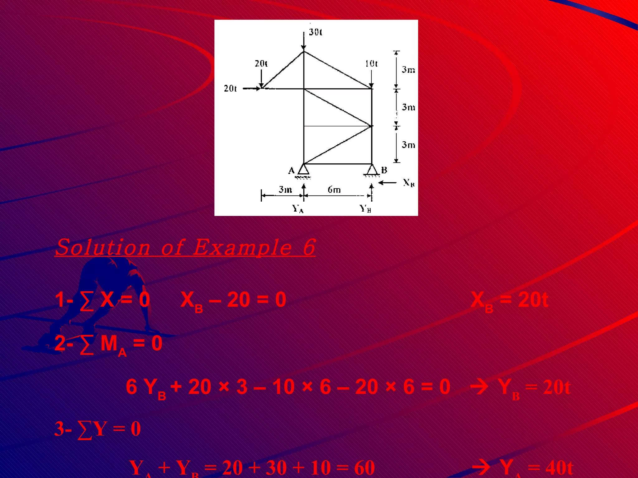
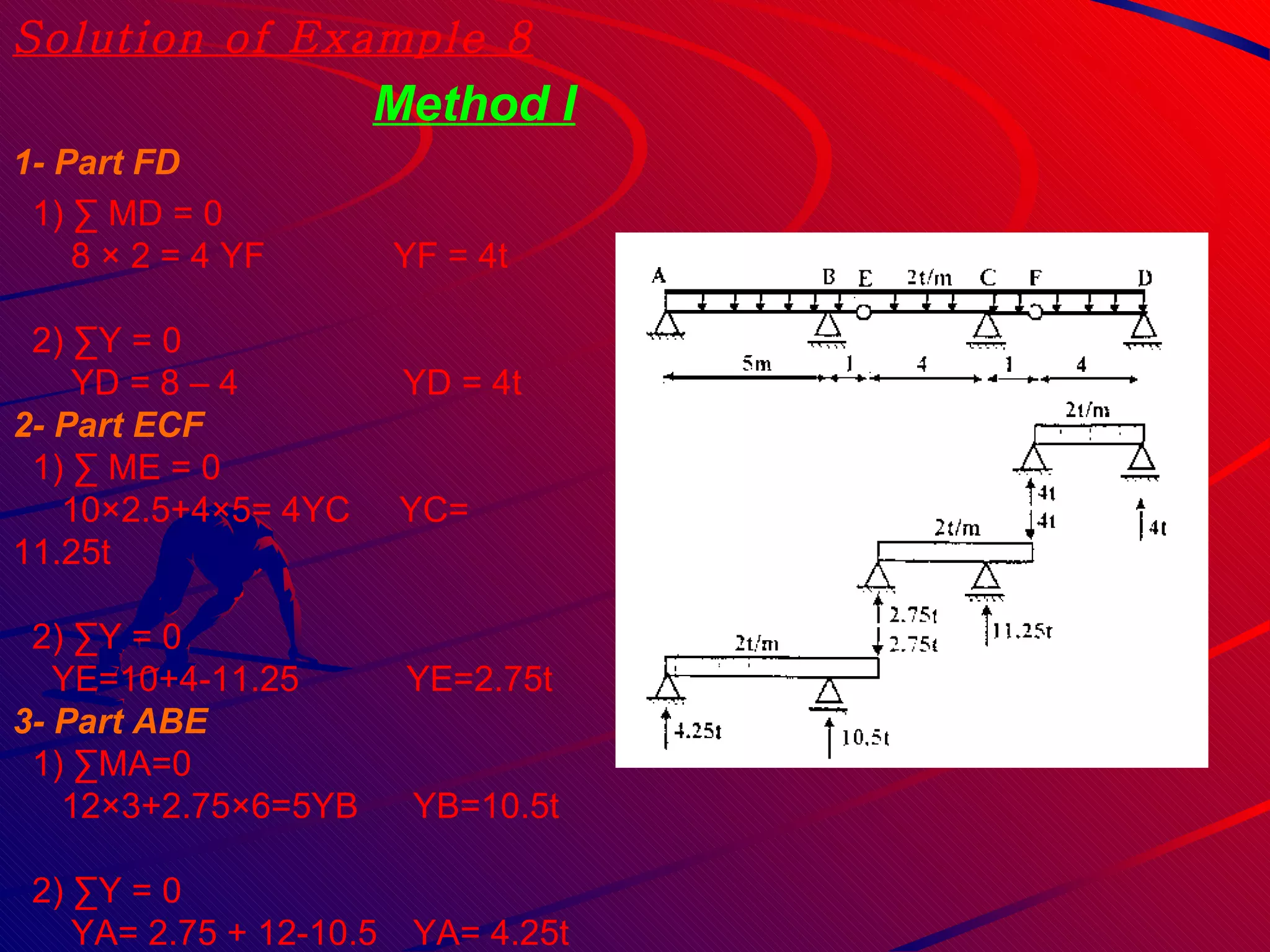
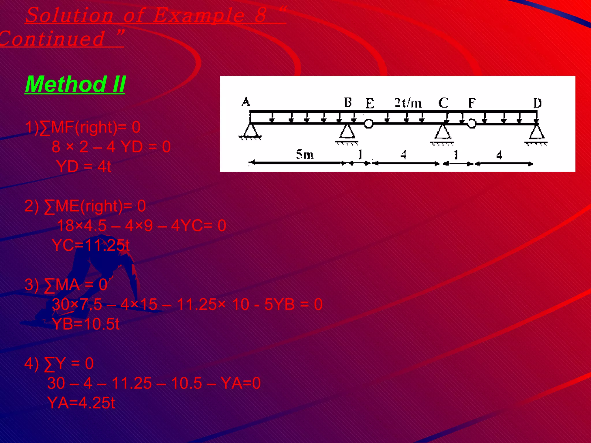
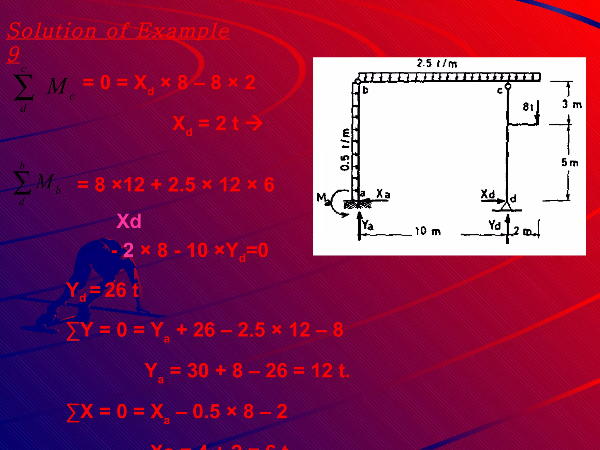
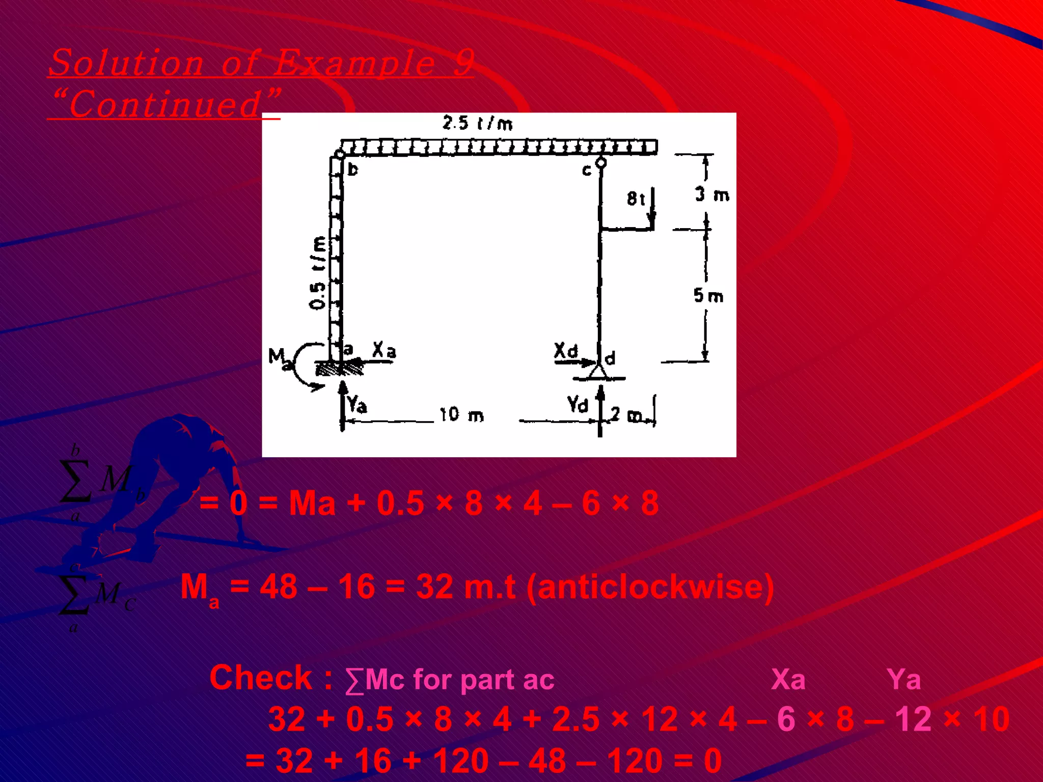
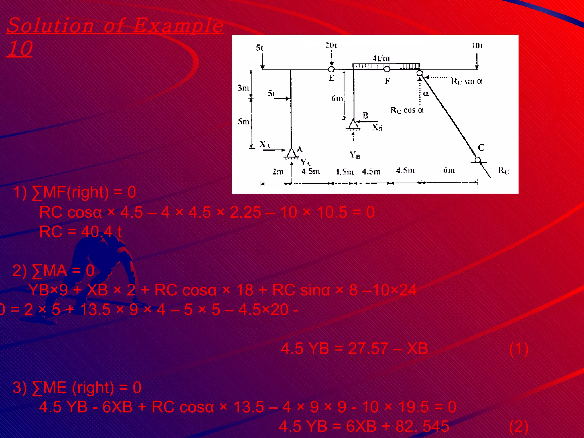
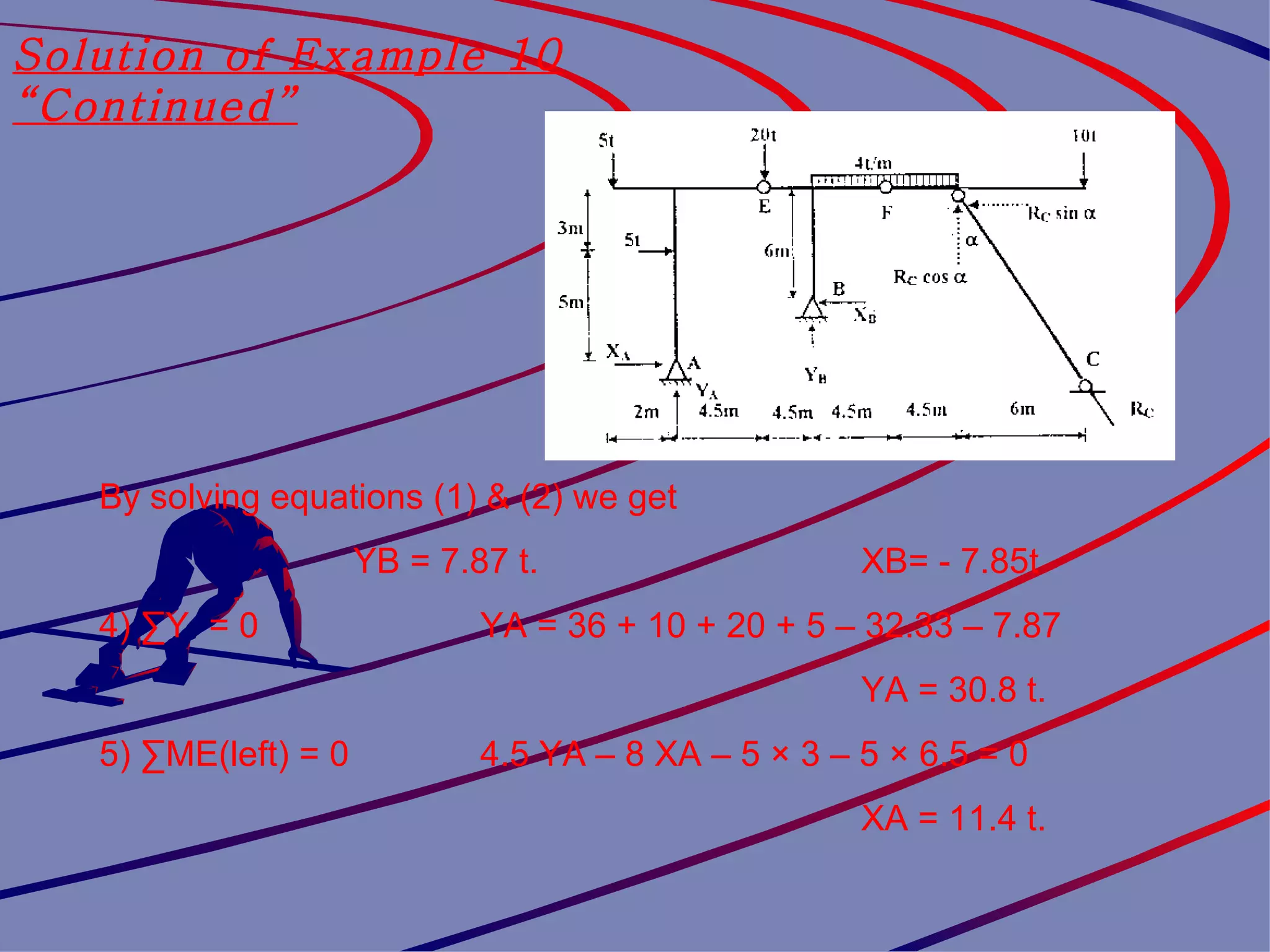
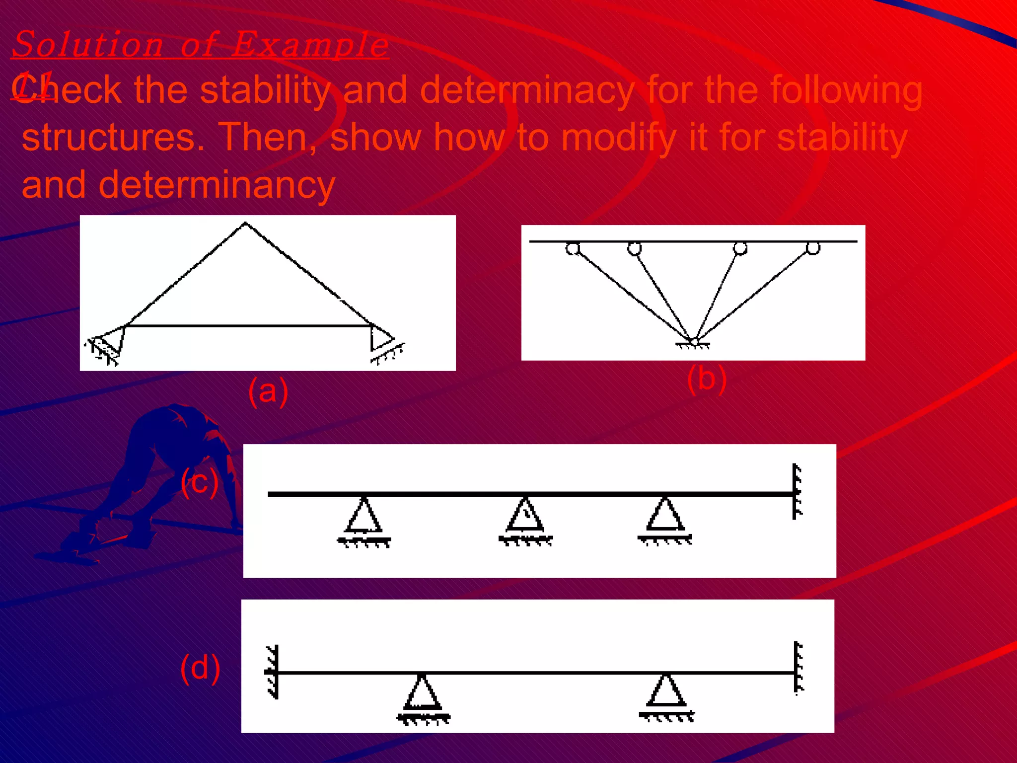
Examples are provided to demonstrate solving for reactions, internal forces, and conditional equations for various statically determinate structures. Factors affecting stability and determinacy are also discussed.


![[Ths]2012 deter-indeter](https://cdn.slidesharecdn.com/ss_thumbnails/ths2012-deter-indeter-111015031149-phpapp02-thumbnail.jpg?width=640&height=640&fit=bounds)